floor cooling project model for a residential building in
TRANSCRIPT

MSc ProgramRenewable Energy Systems
Floor cooling project model for a residential building in thecity of Vienna using ground water (free cooling) and
refrigeration system (Chiller).
A Master's Thesis submitted for the degree of“Master of Science”
supervised byDipl.Ing Dr. Mario Ortner
Sarmad Abdulraheem, BSc of Engineering
11848758
Vienna, 13.05.2021

Affidavit
I, SARMAD ABDULRAHEEM, BSC OF ENGINEERING, hereby declare
1. that I am the sole author of the present Master’s Thesis, "FLOOR COOLINGPROJECT MODEL FOR A RESIDENTIAL BUILDING IN THE CITY OF VIENNAUSING GROUND WATER (FREE COOLING) AND REFRIGERATION SYSTEM(CHILLER).", 66 pages, bound, and that I have not used any source or tool otherthan those referenced or any other illicit aid or tool, and
2. that I have not prior to this date submitted the topic of this Master’s Thesis or partsof it in any form for assessment as an examination paper, either in Austria orabroad.
Vienna, 13.05.2021 _______________________Signature

i
Acknowledgements
This thesis was carried out under the supervision of Dipl. Ing. Dr. Mario
Ortner, to whom I am deeply grateful for his dedication and encouragement
provided during the thesis-writing process, as well as friendliness and
willingness to advise and assist with the information needed for the
completion of this thesis. In addition, I owe my deepest gratitude to Prof
Univ. Prof. Dr. Dipl. Ing. Reinhard Haas, Academic Director at Vienna
University of Technology in Austria for his invaluable support, guidance,
readiness for collaboration.
I would also like to express my appreciation to Mag. Doris Guttmann,
Program Manager at the Vienna University of Technology - Continuing
Education Center, and everyone who participated in the specific courses.
They guided me patiently throughout the entire research and writing
process. They helped me with the implementation of experiments and
analyses. Furthermore, I would like to thank my friends Mustafa Morie,
Rebecca McLeod, and Thomas Unger, who assisted and supported me
during my master's program.
Finally, I would like to extend my wholehearted appreciation to my parents
(my mother, brother, and father) for their encouragement and for having
absolute faith in me.

ii
Abstract The cooling energy consumption takes up around 30–50% of the total
consumption of data centers due to the inefficient cooling system and the
necessity for it. Free cooling is an effective solution for reducing the power
consumption of cooling systems. (H. Zhang, et al., July 2014 pp. 171-182)a
Free cooling is defined as the means to store groundwater coolness or cool
air, to supply indoor cooling during the day, which means to use passive
cooling solutions. Notable progress has been made in this direction. However,
many passive solutions are limited to new projects and sometimes this feature
is insufficient to meet the needs of cooling loads.
The research for this master thesis was conducted on such an example – a
residential building in Vienna using groundwater (free cooling) with a
refrigeration system (chiller) to cool the building by using floor cooling and fan
coils distributor. The cooling requirement for this residential building is at 275
kWc, the free cooling capacity 59 kWc and the total capacity of chiller system
is at 216 KWc.
The free cooling was fairly ineffective due to the increased groundwater
temperature in the last couple of years and the chiller (without free cooling with
groundwater) with a maximum cooling capacity of 216 kWc, cannot meet the
cooling requirements for floor cooling and fan coils with a total of 275 kWc
cover, if the well cooling fails due to the high groundwater temperature.
In this thesis, the free cooling with the design of the chiller system is explained
in detail, followed by reasons for the defects and failure of free cooling.
Furthermore, alternative variants are proposed for the model cooling system
to improve the performance work of the chiller system. Finally, the investment
cost and NPV of the model chiller system for a 20-year span is presented.

iii
Table of content 1. Introduction ................................................................................................................. 1
2. Refrigerants.................................................................................................................. 2
3. Cooling methods ........................................................................................................ 6
3.1. Active cooling ...................................................................................................... 6
3.2. Passive cooling .................................................................................................... 7
3.2.1 Evaporative cooling .................................................................................... 9
3.2.2 Soil cooling ................................................................................................... 9
3.2.3 Ventilation cooling ...................................................................................... 9
4. Free cooling ............................................................................................................... 10
4.1 Airside free cooling ............................................................................................ 11
4.2. Heat pipe free cooling ...................................................................................... 11
4.3. Waterside (groundwater) free cooling ......................................................... 12
5. Types of Air Conditioning system ....................................................................... 14
5.1. Central air conditioning ................................................................................... 15
5.2. Decentralized air conditioning ....................................................................... 15
5.3 Types of ventilation function ........................................................................... 16
6. Types of the refrigeration system ........................................................................ 22
6.1. Solar heating & cooling ................................................................................... 22
6.2. Solar Air conditioning ...................................................................................... 23
7. Types of Refrigeration Cycles ............................................................................... 24
7.1. Adsorption refrigeration machines .............................................................. 24
7.2. Vapor refrigeration machine ........................................................................... 25
8. Modelling of groundwater refrigerant system (Chiller) (The Case Study: The Smart Energy Building) ....................................................................................... 29
9. Thermal Comfort Basics ......................................................................................... 32
10. Cooling with dehumidification ............................................................................ 33
11. Floor cooling ............................................................................................................ 35
12. The refrigeration system (Chiller Case Study).................................................. 37
13. Components of the refrigeration cycle ............................................................. 40
13.1. The evaporator ................................................................................................. 40
13.2. The compressor .............................................................................................. 41
13.3. The condenser ................................................................................................. 42
13.4. The expansion valve....................................................................................... 43

iv
14. Performance indicators for cooling machine system .................................. 43
15. Simulation of different variants on cooling systems .................................... 44
1. Variant: ....................................................................................................45
2. Variant: ....................................................................................................45
3. Variant: ....................................................................................................45 4. Variant: ....................................................................................................45
16. Presentation of results .......................................................................................... 46
17. Calculation ............................................................................................................... 47
18. Conclusion ............................................................................................................... 50
Bibliography: ...................................................................................................................... 52
List of Figures ............................................................................................................... 59
List of Tables ................................................................................................................ 60

1
1. Introduction Energy consumption is an important issue in residential buildings for cooling and
heating demand. Heating buildings consumes more energy than electricity or
transportation, and the heating/cooling demand accounts for around half of global final
energy consumption. “Of this, nearly 50% is consumed in industrial processes, while
another 46% is used in residential and commercial buildings”. (IEA, 2020)
“The demand for heating and cooling is set to keep growing. Cooling demand has
already tripled globally since 1990”. (C. Delmastro, June 2020)
To preserve energy, it is necessary to pursue 2 objectives. Firstly, to reduce the energy
demand and secondly, to meet the existing demand with maximum efficiency.
The use of renewable energy could offer ways to achieve the objectives mentioned
above. Building cooling with the groundwater source (free cooling) is one type of
renewable energy that restores its power periodically. Not only is it a green concept,
since no carbon is burnt for the purpose of cooling, but it also ensures the preservation
of good indoor air quality in the building.
“The energy convenience of such an option depends on the annual energy needs,
population density, and efficiency of heat production”. (M. Imal, 2015 pp. 18-26).
The groundwater thermal environment facilitates lower temperatures for cooling in the
summer season and higher temperatures for heating in the winter season. In addition,
the temperature fluctuates less, especially in comparison to the ambient air
temperature change in extreme weather conditions.
The effect of a significant imbalance of fluid loop temperature (increase/decrease)
between the heat rejection from the groundwater and heat extraction from the
groundwater source on a yearly basis, can be moderated by adding the heat
exchanger size. Furthermore, the groundwater source cooling/heating systems are
economically more advantageous than the conventional heating system.
Moreover, to optimize the operation of groundwater source systems, it is necessary to
develop a system using both groundwater and air sources, in accordance with
temperature conditions and building loads. Furthermore, groundwater usage should

2
be dealt with carefully to prevent ground subsidence and maintain system performance
for a long period.
This thesis examines residential project mistakes in the calculations of the design of
the cooling system and in calculating the temperature for both free cooling and the
outside temperature during summer season.
The planner of the project in question assumed the temperature of groundwater at
around 11.5°C and a cooling load of 18 to 20 W/m2. However, the temperature of the
groundwater is, according to the authorities, higher than the predicted one and the
chiller designed only delivers a maximum of 216 kWc, intended for a theoretical
maximum outside temperature of 32°C. In addition, in the recent years, the outside
temperatures significantly and frequently exceed the theoretical temperature in
summer season because of global warming.
Finally, the focus of this thesis is on the inefficiency of underfloor cooling, which is
generally only suitable for low cooling loads, with low-temperature groundwater as
a justification for this failure.
2. Refrigerants To address and resolve protection and environmental concerns, refrigerants need to
have low toxicity, low flammability, and lengthy atmospheric life. Recently, refrigerants
have come under scrutiny because of the environmental issues attributed to their use
by scientific, environmental, and regulatory groups. Some refrigerants—particularly
chlorofluorocarbons (CFCs)—are devastating for the stratospheric ozone. The relative
cap potential of a refrigerant wrecking stratospheric ozone is referred to as its ozone
depletion potential (ODP). CFCs were closed in accordance with the 1987 Montreal
Protocol. The production of CFCs in certain international locations ceased in 1995, and
their maximum (not unusual) place replacement, halogenated chlorofluorocarbons
(HCFCs), are due for phase-out in the twenty-first century. Replacements for HCFC
R-123 and HCFC R-22, which are typically used inside the industry, are being updated
at the present time. Realistically, however, HCFCs could be manufactured around the
middle of the twenty-first century and, without a doubt, at the lifetimes of machines
presently being manufactured.

3
Table 1: Montreal protocol (Resources, 2009)
Overview of the Global Warming Potential and Greenhouse Gases
The potential global warming and climatic extrude connected to the emission of the
greenhouse gases in the environment present one of the biggest environmental
challenges of our time. The anthropogenic motives of this forthcoming weather
deterioration could be attributed to the use of energy and the combustion of fossil
number one assets of power and the associated emission of CO2 .
The global warming potential of a certain gas refers to the entire contribution to global
warming, because of the emission of one unit of that fuel line, relative to one unit of
the reference gas (i.e., carbon dioxide), that is assigned a price of 1. To calculate the
GWP, the mass of gas is multiplied by its GWP price to get CO2 equal emissions. For
example, if a gas has a GWP of 100, it equals the CO2 emission of two hundred heaps.
The global warming potential (GWP) is a technique for evaluating the weather
consequences of emission, heat tapping cap potential at unique fees, greenhouse
gases, and unique lifetime, using CO2 as a benchmark for measuring the warmth
trapping cap potential of each of the opposite gases.
The European Fluorinated gases (F-gas) regulation has limited the permissible
leakage rates of HFC systems in 2007 and stipulates regular leakage tests for this
purpose. In 2014, there was a revision or a significant tightening of the F-gas
regulation, prohibiting HFC refrigerants with a GWP> 2500 in new systems from
01/01/2020. From 01/01/2022, this prohibition also applies to coolants with a GWP>

4
1500, provided they are used in commercial refrigeration systems with an output of 40
kW or more.
“The greenhouse gases (GHG) that trap heat in the atmosphere are called greenhouse
gases” (EPA, 2009)a. “They let sunlight pass through the atmosphere, but they prevent
the heat that the sunlight brings from leaving the atmosphere” (GARRITY, 2020).
In order to achieve the set climate protection goals, further tightening or revisions of
the F-gas regulation are to be expected. According to current knowledge, in the long
term, only Refrigerants with a GWP <150 (e.g., R290) can be viewed as future-proof.
GWP>2500 New System prohibition
From 01/01/2020
GWP>2500 New System prohibition
From 01/01/2022
Expect continue tightening for R with GWP>150
Figure 1: Global Warming Potential (Witt, 2012)

5
Figure 2: Overview of refrigerants (GIZ, 2018)
There are the 4 main greenhouse gases:
1. Carbon dioxide (CO2): Carbon dioxide enters the ecosystem via burning fossil fuels
(coal, natural gas, and oil), solid waste, trees, and different organic materials, and as
a consequence of positive chemical reactions (e.g., manufacture of cement). Carbon
dioxide is eliminated from the ecosystem (or "sequestered") through plant absorption
as part of the organic carbon cycle.
2. Methane (CH4): Methane is emitted during the production and transport of coal,
natural gas, and oil. Methane emissions also result from livestock and other agricultural
practices and by the decay of organic waste in municipal solid waste landfills.
3. Nitrous oxide (N2O): Nitrous oxide is emitted during agricultural and industrial
activities, combustion of fossil fuels and solid waste, as well as during treatment of
wastewater.

6
4. Fluorinated gases: Fluorinated gases: Hydrofluorocarbons HCFC, perfluorocarbons
PFCs, sulfur hexafluoride SF6, and nitrogen trifluoride are synthetic, effective
greenhouse gases that are emitted from loads of commercial processes. Fluorinated
gases F-fuel is on occasion used as substitutes for stratospheric ozone-depleting
substances (e.g., chlorofluorocarbons, hydrochlorofluorocarbons). These gases are
usually emitted in smaller quantities, however, due to the fact they're amazing
greenhouse gases, they're on occasion called High Global Warming Potential gases
(High GWP gases)”. (EPA, 2009)b
3. Cooling methods
For a better understanding of the possible uses of cooling systems, a general overview
of the types of these systems is necessary. There are two types of cooling methods,
namely active and passive cooling system. The two types will be briefly elaborated on
in the following section.
3.1. Active cooling
Active cooling system is generally used when a high and individually adjustable cooling
capacity is required. The functional principle of the heat pump is the absorption of heat
from outside and the transfer of the heat to the building is reversed. The building,
therefore, functions like a fridge. The heat pump must be equipped with a reversible or
reversible cooling circuit. The original evaporator becomes the condenser, and the
Figure 3: Greenhouse Gas Emission (EPA, 2009)c

7
condenser becomes the evaporator. When the temperatures are higher, the heat pump
absorbs excess room heat and cools it down using the compressor. If an additional
heat exchanger is installed, the resulting waste heat can be used efficiently, for
example, to heat drinking or service water.
3.2. Passive cooling
Passive cooling system refers to the technology or strategies which might be used to
chill the constructing interior with or without minimum electricity usage. In addition, the
heat pump is not used, rather, the cooling machine is in operation, which lowers
electricity costs. Thus, only the circulation pumps in the source and heating circuit
works.
Buildings may be cooled passively at the same time as the usage of numerous natural
warmness sinks, like ambient air, higher atmosphere, below surface soil, etc. Passive
cooling is not quite as effective as active cooling. On the other hand, it is advantageous
because of the lower investment costs and more energy-efficient operation, that is
almost free of climate-damaging CO2 emissions.
The traditional cooling system consumes a large quantity of energy due to three main
reasons:
1. “High energy consumption of cold source (A. Gschwend, et al., 2016 pp. 193-206).
Traditional vapor compression system needs to work all year-round, even at night
or in winter when the temperature is low.
2. Large energy consumption in the piping system. A lot of energy is used by pumps
and fans to transport cold water or air. Meanwhile, long-distance transportation
results in a loss of cold source.
3. Mixing of cold and hot air streams. Entrainment of the hot air into the cold aisles is
widely seen due to the lack of airflow control devices”. (H. Zhang, et al., July 2014
pp. 171-182)b (J. Rambo, 2006 pp. 923-945)

8
The efficiency of the cooling system for the second and third aspect presented above,
can be improved by using control methods proposed by scholars, that include utilizing
frequency conversion fans, ceiling coolers, optimizing the structure of perforated tiles,
the relative position of racks, and the mode of supply and return air. Moreover, the
solution for the primary aspect is the use of free cooling technology.
Furthermore, passive cooling techniques are classified according to the natural source
from where the cooling energy is derived. The classification of the passive cooling
techniques is presented and explained in the figure below.
Figure 4:Classification of passive cooling techniques for building applications. (Givoni, 1994)a
Passive cooling benefits from the fact that the temperature in the ground is around 10
to 14°C all year round at a depth of 15 meters. In Summer, the ground creates one
cold storage and one heat source in Winter. The heat supply in Summer can increase
the temperature of the ground. This reduces the cooling effect, but it does in turn make,
the subsequent heating with the heat pump more effective in Winter. In addition, a
combination of active and passive cooling is also possible: For example, it is advisable
to first use energy-saving passive cooling when there is less cooling demand and when
it is larger switch heat to active cooling.
9
3.2.1 Evaporative cooling
“Evaporative cooling is the technology for the cooling of air by the evaporation of water.
When water evaporates, it absorbs heat from the surrounding air and consequently,
the air is cooled. After water evaporates, it enters the air as water vapor and transmits
the heat absorbed during evaporation back to the air in the form of latent heat.
Therefore, the air is humidified, and the total heat, or enthalpy, of the air, hardly
changes. The humidified and cooled air is used in the building for cooling purposes
and the process is known as direct evaporative cooling which is most suitable in dry
and hot climates. In indirect evaporative cooling of the air, adding moisture to the air is
avoided by separating water and air, which makes it more attractive in humid climates”.
(Y.M. Xuan, et al., 2012 pp. 3535-3546), (A. Waqas, 2013 pp. 607-625)a, (R. Velraj,
2012), (R. R. Kolhekar, 2020)
3.2.2 Soil cooling
Hot ambient air can be cooled down by installing a heat exchanger that is buried 2–3
meters below the earth surface, which causes air circulation (S. Guevara, 2011). The
earth’s surface holds a stable temperature at a depth of approximately 2–3 m, which
is below the average ambient temperature,. “Soil cooling implemented in desert
climate may reduce the peak indoor temperature by 3 °C during hottest Summer
months”. (A. Waqas, 2013 pp. 607-625)b
3.2.3 Ventilation cooling
Ventilation techniques can be used to improve the enjoyment conditions of buildings.
One of these techniques is to provide the physiological cooling effect for the building
occupants by introducing sparkling cool ambient air in the construction at better air
velocity. “The physiological cooling effect is provided by opening the windows, or
doors, through cross ventilation, or by electric fans” (A. Waqas, 2013 pp. 607-625)c to
let the ambient air in, thus providing a higher indoor airspeed and having tenants feel

10
the decrease in temperature. Physiological cooling is normally used when the ambient
temperature is lower than the indoor temperature.
4. Free cooling
Free cooling is an effective way to decrease the energy consumption of compressor-
based cooling, which is commonly known as the economizer cycle. It captures and
preserves the cold air in the heat source at night , and it absorbs heat during the day
when building temperatures are high.
In free cooling, a storage medium is used to accumulate the cold air when ambient
temperature is lower than room temperature, and the stored cold air is extracted from
the storage medium whenever it is needed, by using an electric fan. The storage
medium for free cooling is normally in the form of sensible and latent energy type.
“When the outdoor temperature is sufficiently below the data center temperature, the
heat will naturally flow to the outside without the need for the “temperature boost”
provided by the compressor and the vapor-compression refrigeration system, so its
function is unnecessary. Therefore, under favorable conditions, the compressor can
be bypassed, which can save energy significantly” (H. Zhang, et al., 2014 pp. 171-
182)c. When the compressor is bypassed, economizers are used to exploit natural cold
sources. Two categories of economizers are currently in use, i.e., the waterside
economizer and airside economizer.
The main difference between free cooling and nocturnal ventilative cooling is that in
nocturnal ventilative cooling, the building structure (like walls) acts as “the storage
medium while in free cooling technique, a separate thermal storage unit is used for the
storage of the cold” (A. Waqas, 2013 pp. 607-625)d and a mechanical device, such as
a fan, is used to store and extract the cold from the storage unit. The vantage point of
free cooling over nocturnal ventilative one, is that the accumulated cold can be
extracted whenever it is needed by circulating ambient or room air through the storage
unit.

11
There are three categories of free cooling system, and they will be elaborated on the
in the following sections.
4.1 Airside free cooling
“Airside free cooling systems make use of outside air for cooling” (H. Zhang, et al., July
2014 pp. 171-182)d. In this system, sensors are used for monitoring outside and inside
air conditions and temperatures. When the outdoor temperature is fitting, the airside
economizers draw the air from outside directly inside or utilize the outside air cooler
indirectly with air-to-air heat exchangers. Airside free cooling is a technology with wide
application prospect.
4.2. Heat pipe free cooling
Heat pipe heat exchanger (including thermosyphon) has superior temperature control
features and the ability to transfer heat at small temperature differences without
external energy, which is suitable for utilizing natural coldness sources.
Figure 5:Schematic diagram of direct airside free cooling (J Niemann, 2011 p. 132)
12
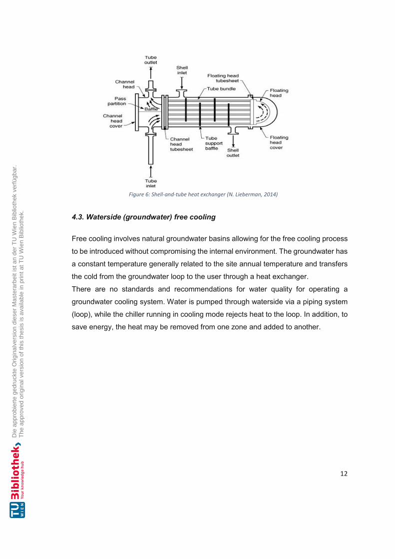
4.3. Waterside (groundwater) free cooling
Free cooling involves natural groundwater basins allowing for the free cooling process
to be introduced without compromising the internal environment. The groundwater has
a constant temperature generally related to the site annual temperature and transfers
the cold from the groundwater loop to the user through a heat exchanger.
There are no standards and recommendations for water quality for operating a
groundwater cooling system. Water is pumped through waterside via a piping system
(loop), while the chiller running in cooling mode rejects heat to the loop. In addition, to
save energy, the heat may be removed from one zone and added to another.
Figure 6: Shell-and-tube heat exchanger (N. Lieberman, 2014)

13
Heat Pumps vs. Air Conditioners
“When looking for an HVAC system to cool your home, either a heat pump or air
conditioner will do the job. Both systems use compressed refrigerants to collect heat
from inside your home as air passes over the coil in the air handler and transfer it
outside. Heat pumps and air conditioners essentially move heat from inside your home
to an outdoor location. The heat pumps and air conditioners are essentially the same
when operating in cooling mode, with no significant difference in operation, efficiency,
or energy costs. While essentially identical in cooling mode, the heating mode is a
completely different story. Air conditioners do not provide heating, but heat pumps do.
“A heat pump can heat and cool, but an air conditioner cannot, which is the primary
difference between the two HVAC systems” (Energy, 2012). An air conditioner is
typically paired with a furnace to provide heat during the cold months. “Together, an
air conditioner and furnace are a complete heating and cooling system” (Viñolo, 2020).
In addition, a heat pump can heat a home, when outside temperatures drop below
freezing. Typical heat pump systems have an auxiliary electric heater added to the
indoor unit to add supplemental heat when outdoor temperatures drop.
The energy-efficient heat pump systems provide heating using only electricity. In these
conditions, they can be less costly to operate compared to systems that use more
expensive heating fuel sources such as natural gas, oil, or propane. If temperatures
drop below freezing, the heat pump requires more energy to maintain comfort inside,
Figure 7:Principle of the open groundwater system (Willemsen, 2018)

14
reducing efficiency and increasing the electricity required. We can solve this problem
by creating a Hybrid Heat system.
In cooling mode, both heat pumps and air conditioners come in models with high SEER
ratings, providing energy-efficient cooling during the warm summer months, the higher
the SEER, the more efficient the unit. In heating mode, heat pump efficiency is
expressed in COP. The higher the COP, the higher the efficiency. In areas with
moderate temperatures, a heat pump is a better option for efficient heating than air
conditioners”. (Carrier, 2021)
5. Types of Air Conditioning system
In ventilation systems, where the outdoor air that is drawn in is only heated, air
conditioning systems fulfil four thermodynamic functions, namely heating, cooling,
humidifying, and dehumidifying. They keep the temperature, the humidity, and the
purity of the air at specified values all year round. If one of the functions is missing, it
is a partial air conditioning system. Depending on the mode of operation and
installation location, air conditioning systems can be installed in:
1. Central systems
2. Decentralized systems
3. Types of ventilation function in:
a) Air-only systems
b) Air-water systems
c) Air-refrigerant systems
d) Water-only systems
Furthermore, there are two types of cycle chillers:
1. Chillers with electric compressors
2. Chillers with thermal compressors (absorption chillers)

15
5.1. Central air conditioning
Central air conditioning system carries out all the necessary air conditioning in a central
supply air device and in a central exhaust air device. Air ducts are distributed from the
control center to the individual rooms, which is often the case with hotels or large
modern public buildings. Moreover, if a larger cooling capacity is required (from approx.
50 kW), central systems with cold water generators, which use R407C and R410A as
refrigerants, are utilized. Turbo chillers are also used when the cooling capacity is 250
kilowatts or higher, and have R134a as a refrigerant.
5.2. Decentralized air conditioning
Decentralized air conditioning systems carry out the air treatment, conveying, filtering,
and controlling temperature directly in the room. Examples of decentralized air
conditioning units are split systems, door air curtains, façade fans, and fan coil units.
Furthermore, decentralized air conditioning systems, although similar in structure,
cannot be equated with room’s air conditioning units.
Figure 8:Central air conditioning (Bott, 2016)

16
5.3 Types of ventilation function
5.3.1. Air-only systems
In air-only systems, the air is processed exclusively with the fresh air supplied. This
process takes place in central devices that are built into a ventilation center, and
depends on the air-only systems, especially in larger rooms such as halls, theatres, or
meeting places. Depending on the type of volume flow, a distinction is made between
single-channel systems with variable (VVS) and constant (KVS) volume flow. Two-
channel systems can also be found in the building stock.
Figure 10: Air-only system, single-channel system Source: VDI Lexicon
Figure 9: Fan coil unit (left) and door air curtain device (right) (Sabiatech)

17
In single-channel KVS systems, a central device feeds the conditioned air to one or
more rooms via the air duct, keeping the volume flow at a constant. Moreover, same
state supply air flows into all rooms. The individual regulation of the heat demand is
only possible with additional radiators. Furthermore, typical applications of a single-
channel KSV system are buildings with individual rooms such as theatres, cinemas,
assembly rooms, or halls. In contrast, in single-channel systems with variable supply
air (VAV systems), the supply air temperature for the individual rooms is constant. The
different heating and cooling loads of the individual zones are compensated by a
volume flow controller which changes the supply air. Additionally, VAV systems are
used in offices or laboratories.
5.3.2. Air-water systems
The air conditioning of an air-water system does not only take place in the air
conditioning center. Rather, the basic preparation of the outside air, and where it takes
place, depends on the outside temperature (primary air). An additional water system
(two, three, or four-pipe system) supplies the local heat exchangers with hot/cold
water. Moreover, induction devices and fan coil systems (fan convectors) are mainly
used.
Induction systems
The central air conditioning unit prepares the so-called primary air. It corresponds to
the minimum outside air rate and is constant over the entire year. The primary air flows
to the individual induction devices in the rooms. From the rooms, it flows out of nozzles
into the room at high speed, tearing them in the processed secondary air with
induction. Compared to air-only systems, the air volume flow is reduced to 25 to 30%
much faster. Moreover, induction systems are mainly used as high-speed systems
(high-pressure induction systems). Induction devices are available for installation in
parapets, floors, and ceilings.

18
Fan coil systems (fan convectors): Fan convectors are functionally comparable to
induction devices; the difference is in the drive. Instead of nozzles, the air is blown into
the room by a radial fan. Convectors are for the Ceiling and parapet set up available.
Typical air intake /Air outlet temperatures are 23 ° C / 15 ° C.
5.3.3. Air-refrigerant systems
The decentralized air-refrigerant system is a combination of a KVS and a split system,
and consists of an inner part (evaporator) which extracts the heat from the room, and
an outer part (Condenser) which releases heat into the environment. Because of the
use of a split system, the air can only be cooled and dehumidified in one room or
Figure 11:Induction system air/water
Figure 12:Fan coil air/water

19
heated in heat pump mode, whereas the outside air is supplied by a KVS system. The
HFC blends R407C and R410A are predominantly used.
VRF systems: VRF (Variable Refrigerant Flow) multi-split systems are further
developed split systems. They are the air conditioning system that takes up the least
amount of space. With them, an external unit supplies several split units with air outlets
in many rooms.
The most common are air/air refrigeration systems with electric heat pumps, but there
are also systems with an integrated gas heat pump. They are installed as two- and
three-wire systems. With an external unit, all rooms can only be cooled or only heated.
The three-line systems have an additional refrigerant line and switchover unit., where
an outdoor unit can be used to variably heat or cool different rooms. An internal "heat
shift" is possible. In addition, a part of the connected decentralized indoor units can be
used for heating, and another part can simultaneously be used for cooling. The
external unit links the energy flows, which enables high efficiency of air conditioning.
Figure 13: VRF system (MERRETT, 2019)

20
For security reasons, the use of hydrocarbons in multi-split or VRF systems, in which
a connection between refrigerant-carrying components and rooms where people are
staying (apartments, offices), apart from the larger filling quantities. VRF systems are
also available with refrigerant carbon dioxide (R744), that, however, have significantly
lower COPs than the HFC standard variants.
5.3.4. Water-only systems
Water-only systems, additionally referred to as silent cooling systems, no longer have
an air change function. These include cooling ceilings, sails, and convectors as well
as concrete core activation. Separate ventilation devices may be used to cover a
hygienic exchange of air.
Surface cooling systems: cooling ceilings and cooling sails dissipate high cooling
loads. They offer a great deal of design freedom and more comfort because of low
drafts and flow noises. Unlike conventional ventilation, only small temperature
differences arise, which increases the thermal comfort in a room. Surface cooling
systems work as follows: for cooling purposes, cool water (usually 16 ° C) flows
through a pipe network and cools the room air. The cooling ceiling should be combined
with a dehumidification system for an optimal indoor climate. Moreover, cooling ceilings
are connected to the heating or cooling water systems for media supply.
Figure 14:VRV Multisplit System (Nelson, 2021)

21
Depending on where they are used, surface cooling systems are divided into ceiling,
wall, and floor cooling systems. Closed ceiling cooling surfaces can perform from 80
to 100 W/m². Systems in the form of metal panels and coffered ceilings with pressed
pipe coils and thermal insulation are used. The open ceiling cooling surfaces (100 to
130 W/m²) include cooling plates and cooling sails, where parts of the ceiling surface
are suspended for cooling sails. For plastered cooling ceilings, capillary tube mats are
inserted into the ceiling plaster and plastered over. In addition, a form used is specially
developed sandwich panels with foamed-in Capillary tube mats. They combine the
cooling ceiling with a PCM latent heat storage system and work by means of radiation
and convection. Each room and each zone can be air-conditioned separately via a
temperature controller and have a dew point monitor to prevent condensation.
Component activation: “Thermal component activation or concrete core activation
describes cooling systems (also heating systems) that use the building mass for
temperature control. During component activation, meander-shaped pipe systems,
mostly made of plastic, laid in concrete floors. The cooling medium is water” (Glück,
1999). During the day, heat loads are stored in the concrete, and at night, the concrete
releases its heat back into the cooling water. Thermal component activation is suitable
for the cooling mode with heat pumps.
Apart from the systems already elaborated on, there are additional ones, which are
discussed in the following part. These are mobile room air conditioners, which, if not
installed in a fixed location because of their compact design, they have smaller
refrigerant fill quantities and less tendency to leak. However, this type of devices
cools rooms. They are far less effective than split air conditioning units, as the heat
extracted from the room is transported outside using a hose, by means of an air
stream. This leads to negative pressure, creating warm air flows into the room
coming from the outside. If the exhaust air hose is not routed through a hole in the
wall, but through an open window, the cooling effect is very low. The room
temperature is then only a few degrees lower than the outside temperature.

22
6. Types of the refrigeration system (Direct use of solar thermal heat, absorption)
Unfortunately, the majority of the population is unaware of the fact that heating
buildings consume extra energy than that used for electricity or transportation, thus
growing “the use of solar thermal energy is not only important but timely as our demand
for energy continues to steadily grow” (SHC, 2020).
Solar thermal energy is suitable for both heating and cooling. “Key applications for
solar technologies are those that require low-temperature heat, such as domestic hot
water heating, space heating, pool heating, drying processes, and certain industrial
processes” (M. Treberspurg, 2011 ). Solar applications also can meet cooling needs,
where the supply (sunny summer days) and the demand (desire for a cool indoor
environment) are well-matched”. (SHC, 2020)
6.1. Solar heating & cooling
Solar heating utilizes daylight to warm up water or air in buildings. “There are two types
of solar heating, passive and active. A building roof with flat-plate collectors that
capture solar energy to heat air or water. Passive heating relies on architectural design
to heat buildings” (Encyclopaedia, 2018). “The Summer sun, which heats up offices,
also delivers the energy to cool them. The thermal use of solar energy offers itself” (G.
Med El-Amine, 2013)a.
“Days that have the greatest need for cooling are also the very same days that offer
the maximum possible solar energy gain” (TechDev, 2021).
“The demand for air conditioning in offices, hotels, laboratories or public buildings such
as museums is considerable” (G. Med El-Amine, 2013)b. This is not only the case in
Southern, but also in Middle Europe.
“Under adequate conditions, solar and solar cooling systems can be reasonable
alternatives to conventional air conditioning systems. Such systems have advantages
over those that use problematic coolants (CFCs), not to mention the incidental CO2
emissions that are taking on increasingly critical values” (V.K. Sharma, et al., 2010).

23
6.2. Solar Air conditioning
“Should buildings be cooled with the help of solar energy, then water-assisted air
conditioning systems or ventilation systems can be powered with heat that is made
available by solar collectors” (S.S.Verma, 2015)a. The sun can, at least seasonally. at
middle to higher latitudes, provide a substantial part of the energy needed for air
conditioning. Moreover, a combination of water-assisted structures and airflow
structures is also a possibility. “The basic principle behind (solar) thermal driven
cooling is the thermo-chemical process of sorption: a liquid or gaseous substance is
either attached to a solid, porous material (adsorption) or is taken in by a liquid or solid
material (absorption)” (Hug, 2009)a.
“The sorbent (i.e., silica gel, a substance with a large inner surface area) is provided
with heat (i.e., from a solar heater) and is dehumidified. After this "drying", or
desorption, the process can be repeated in the opposite direction. When providing
water vapor or steam, it is stored in the porous storage medium (adsorption) and
simultaneously heat is released. Processes are differentiated between closed
refrigerant circulation systems (for producing cold water) and open systems according
to the way in which the process is carried out: that is, whether or not the refrigerant
comes into contact with the atmosphere. The latter is used for dehumidification and
evaporative cooling. Both processes can further be classified according to either liquid
or solid sorbents” (Hug, 2009)b.
Figure 15: Solar-Assisted Cooling and Air-Conditioning (S.S.Verma, 2015)b

24
7. Types of Refrigeration Cycles
There are various kinds of refrigeration cycles, however, the two most relevant ones
i.e., the adsorption refrigeration and vapor refrigeration machines, are discussed in the
sections below.
7.1. Adsorption refrigeration machines
“Closed absorption refrigeration machines with liquid sorbent (water-lithium bromide)
are most often operated in combination with heat and power generation (cogeneration)
(i.e. with block unit heating power plants, district heating), but can also be assisted by
vacuum tube solar collectors (These systems work with lower hot water temperatures
from approx. 60 - 80 °C)” (Hug, 2009)c, which is easier for solar heat generation flat
plate collectors and is, thus, beneficial. The refrigerating machine is composed of two
adsorbers, an evaporator and a condenser. The refrigeration process does not take
place continuously. Moreover, the refrigerant is enclosed in a solid material and must,
therefore, be cycled between adsorption and desorption. The circuit can be changed
by switching of the heating and cooling.
“An adsorber chamber takes up the water vapor, which is transformed into the gas
phase under low pressure and low temperatures (about 9°C) within the evaporator.
Granulated silicate gel, well known as an environmentally friendly drying agent, then
accumulates it (adsorbs the water vapor). In the other sorption chamber the water
vapor is set free again (the chamber is regenerated or "charged") by the hot water from
the solar collector (about 85°C). The pressure increases and at the temperature of the
surroundings (30°C) the water vapor can be transformed once again into a fluid within
a cooling tower (condensed)” (Hug, 2009)d. Through a butterfly valve the water is led
back into the evaporator and the cycle begins anew.

25
7.2. Vapor refrigeration machine
Refrigerating machines such as heat pumps are based on a thermodynamic cycle.
A simple refrigeration machine consists of four components, namely, a compressor, a
condenser, an expansion valve, and an evaporator. They are connected in a circuit
which is filled up with a fluid called refrigerant. In the case of a refrigeration machine -
in contrast to the heat pump - the heat Q (add) supplied to the refrigeration machine is
viewed as a benefit, because the evaporator acts as a heat exchanger in which heat
Figure 17: Absorption chiller (Ketfi, 2015)
Figure 16:Main components of the system at the University Clinic of Freiburg: Adsorption

26
is transferred from the heat source to the refrigerant. This causes the refrigerant to
evaporate, because the heat supplied to the refrigeration machine is extracted from
the room and cooled. After evaporation, the refrigerant is drawn into the compressor
for compression, which causes an increase in pressure and temperature of the
refrigerant, thus making it possible for the refrigerant to reject heat back to the
secondary circuit in the condenser at a higher temperature. The heat Q (reject)
dissipated from the refrigeration machine can, except in domestic water systems,
usually no longer be used and must be re-cooled (air or water). The heat transfer from
the refrigerant to the condenser, causes the refrigerant to cool down and condense,
after which it enters the expansion valve. Then, the refrigerant expands in expansion
valve, which causes a reduction in pressure and temperature. When the refrigerant
enters the evaporator again, the decrease in temperature allows the refrigerant to
extract heat from the heat source again, completing the cycle.
Overview of Hybrid cooling systems and groundwater source
Ground source cool/heat systems (GSHP,) additionally called geothermal heat pump
(GHP) systems, are an energy-efficient alternative for heating and cooling of
residential, commercial, and institutional applications. The moderate and constant
earth temperatures used by the GSHP system as a heat sink/source are more
Figure 18:Single-stage electric chiller (ARANER, 2021)

27
advantageous than the outdoor air used by air-source heat pump systems.
Furthermore, the system usually consists of a ground loop heat exchanger (GLHE),
through which water or an antifreeze solution circulates, and one or more water-source
heat pumps. The advantages of using a GSHP system are higher energy efficiency in
comparison to conventional systems, lower CO2 emissions, and lower maintenance
costs. Although the system is beneficial, GSHP system market penetration has been
limited because of its high initial costs.
Water loop heat pump systems (WLHP) are heating and cooling structures that can be
used in residential and institutional applications to provide space heating and cooling
for multiple zones. Typically, a heat pump is placed in each building zone to meet its
heating and cooling demands, and the water is pumped through each heat pump via
a piping system (loop). Moreover, heat pumps running in heating mode remove heat
from the loop, while heat pumps running in cooling mode reject heat to the loop. The
water is maintained at desired temperatures with the assistance of a heat rejecter, e.g.,
cooling tower or fluid cooler, and a heat source, such as a heat exchanger. When the
system is running with some heat pumps for heating and others for cooling, heat that
may be removed from one zone can be added to another, thus saving energy. Figure
20 shows a typical WLHP system with a water-to-water heat exchanger. The experts
put much emphasis on energy conservation and lower initial cost, which is why WLHP
systems have become increasingly popular.
Figure 19:Schematic of a typical GSHP system (Y.Kim, 2016 pp. 331-357)

28
Types of Cooling Towers
“Cooling towers come in a variety of shapes and configurations. A “direct” tower is one
in which the fluid being cooled is in direct contact with the air. This is also known as an
“open” tower. An “indirect” tower is one in which the fluid being cooled is contained
within a heat exchanger or coil and the evaporating water cascades over the outside
of the tubes. This is also known as a closed-circuit fluid cooler.
The tower airflow can be driven by a fan (mechanical draft) or can be induced by a
high-pressure water spray. The mechanical draft units can blow the air through the
tower (forced draft) or can pull the air through the tower (induced draft). The water
invariably flows vertically from the top down, but the air can be moved horizontally
through the water (crossflow) or can be drawn vertically upward against the flow
(counterflow)” (K. Peterson, 2018).
The most common types of cooling towers encountered in the HVAC chilled water
plant are:
Spray towers
Forced draft cooling towers
Figure 20:Schematic of a WLHP system with water-to-water (Z. Tu, et al., 2020 )

29
Induced draft cooling towers
When designing energy-efficient central chilled water plants, it is critical to select the
right condenser water system. The efficiency of the chillers is affected, not only by the
operation of the cooling towers and associated pumps, but also by the temperature
and quality of the condenser water.
Piping Heat Recovery Options
Heat rejected from chillers may be utilized in several ways, inclusive preheating
domestic hot water and heating buildings, with the usage of double-package bundle
heat recovery chillers. In the case of preheating domestic hot water, the condenser
water is routed via a double-wall warmness exchanger that is either an indispensable
part of a storage tank or is remotely positioned with a stream pump to the storage tank.
8. Modelling of groundwater refrigerant system (Chiller) (The Case Study: The Smart Energy Building)
The groundwater systems (Free cooling) need a complementary framework,
interpretation of interaction, feedback, and adaptable and dynamic control
interpretations. These are the key elements for an optimal and sustainable use of the
subsurface. Using free cooling and low-temperature floor, with a temperature change
of a few Kelvin between two wells, is sufficient to efficiently cool. The buildings can be
efficiently cooled in the Summer using groundwater from the cold well. Overall, a
groundwater system requires less primary energy use for heating and cooling of
buildings. If the cooling is carried out by the well, it is called free cooling. The heated
groundwater is then returned to the groundwater source via two injection wells. The
paper examines the cooling case in summer. The supply cold takes place, on the one
hand with groundwater via a suction well with a planned discharge capacity of 66 m3/h
(18.33 litres/s), and on the other hand, if the cooling capacity of the groundwater during
summertime is not sufficient, it is possible to use a cooling machine (chiller) to achieve
the cooling demand.

30
The cooling coil temperatures for floor cooling of rooms, and fan coils for flow and
return are designed for 16°C/ 22°C. Therefore, the groundwater is prioritised since it is
available free of charge. In addition, a separating heat exchanger must be connected
between the groundwater circuit and the cooling circuit to avoid contamination of the
internal circuit.
Figure 22:Electric refrigeration machine (X. Chen, et al., 2019)
Figure 23:Extraction and reinjection of groundwater (Beanland, 2019)

31
The heat dissipation of the refrigeration machine by condenser takes place on the roof
of a building, using an air/water heat exchanger and a heat exchanger connected in
series with a groundwater source. The heat exchanger (evaporator and condenser) is
tested and stamped for a maximum operating pressure P of 3200 kPa on the
refrigerant side and 1000 kPa on the waterside. “This cooler with groundwater is
bypassed with 100% free cooling” (N. Lal. Shrestha, et al.). In designing energy-
efficient central chilled water plants, it is extremely important to select the proper
condenser system. Moreover, the efficiency of the chillers is affected not only by the
operation of the cooling towers and associated pumps, but also by the temperature
and the quality of the condenser.
Figure 24:Separation heat exchanger (Dwyer, February 2017)
32
9. Thermal Comfort Basics
Thermal comfort depends on certain influencing factors, e.g., a room climate that is
conducive to health exists when the heat of the human body is balanced (heat
emission = heat generation). Thus, the body's own heat production depends on the
degree of workload (level of activity). The factors that are decisive for heat emission
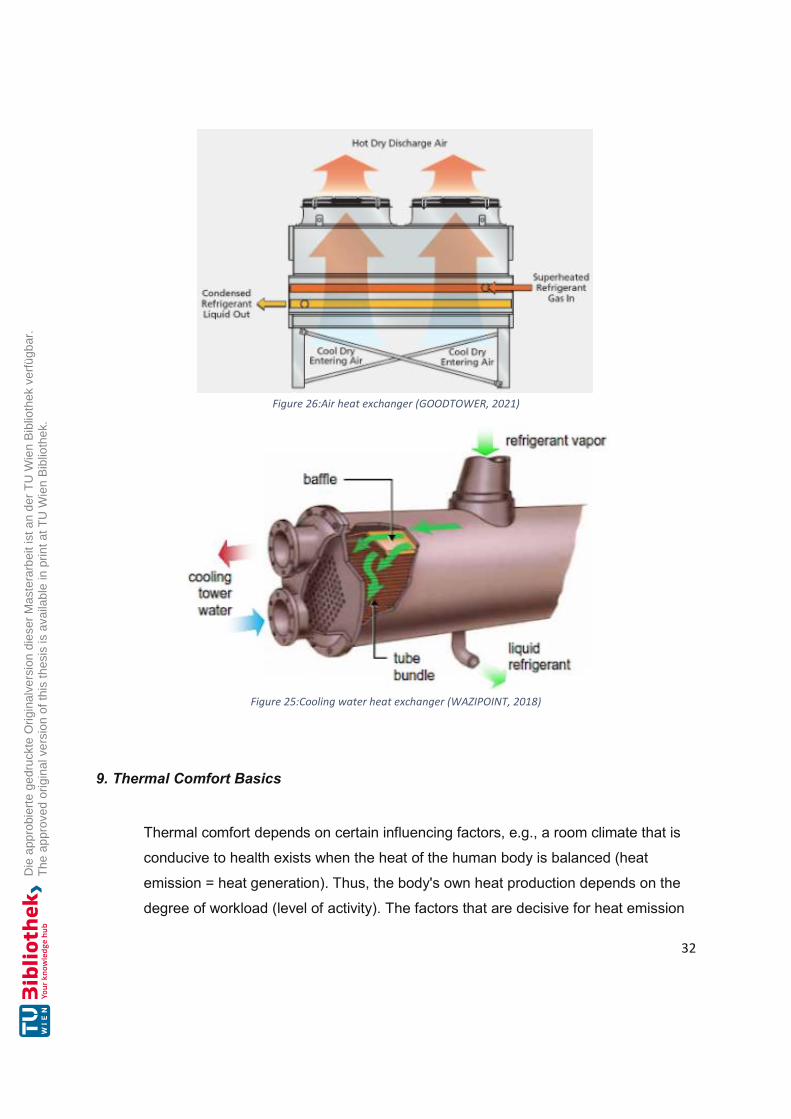
Figure 26:Air heat exchanger (GOODTOWER, 2021)
Figure 25:Cooling water heat exchanger (WAZIPOINT, 2018)

33
are air temperature, room enclosing surface temperature, air speed, air humidity, and
clothing. In general, people respond to this rapidly, adapt to thermal stimuli
(adaptation) and adjust to the thermal environmental conditions in the long term
(acclimatization). However, based to the multitude of factors mentioned above, it
becomes clear that comfort is perceived differently from one individual to the next
and that there cannot be an optimal room climate. Therefore, it can only be spoken of
a comfort zone in which some people are satisfied with the indoor climate. Are
several influencing factors such as air temperature and humidity considered
simultaneously with their specific comfort zones, comfort fields result?
Recommendations for the relative humidity are between 35% and 65% with indoor air
temperatures between 18°C and 23°C.
10. Cooling with dehumidification
Humidification and dehumidification are vital processes in air conditioning and
refrigeration for controlling the air moisture supplied to space. The dehumidification
process in which the air is cooled sensibly, and at the same time from which moisture
is removed, is called cooling. The cooling and dehumidification process is obtained
Figure 27: Comfort room area air humidity - room air temperature according to Frank (A. Dietrich, 2006)b
Comfortable Zone
Too wet
Too dry Still comfort
Room air temperature
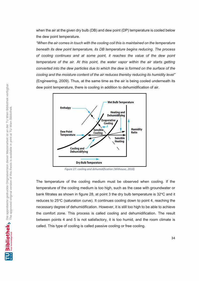
34
when the air at the given dry bulb (DB) and dew point (DP) temperature is cooled below
the dew point temperature.
“When the air comes in touch with the cooling coil this is maintained on the temperature
beneath its dew point temperature, its DB temperature begins reducing. The process
of cooling continues and at some point, it reaches the value of the dew point
temperature of the air. At this point, the water vapor within the air starts getting
converted into the dew particles due to which the dew is formed on the surface of the
cooling and the moisture content of the air reduces thereby reducing its humidity level”
(Engineering, 2009). Thus, at the same time as the air is being cooled underneath its
dew point temperature, there is cooling in addition to dehumidification of air.
The temperature of the cooling medium must be observed when cooling. If the
temperature of the cooling medium is too high, such as the case with groundwater or
bank filtrates as shown in figure 28, at point 3 the dry bulb temperature is 32oC and it
reduces to 25oC (saturation curve). It continues cooling down to point 4, reaching the
necessary degree of dehumidification. However, it is still too high to be able to achieve
the comfort zone. This process is called cooling and dehumidification. The result
between points 4 and 5 is not satisfactory, it is too humid, and the room climate is
called. This type of cooling is called passive cooling or free cooling.
Figure 27: cooling and dehumidification (Withouse, 2018)

35
However, the cooling medium temperature can be cooled down to approx. 10 °C (see
point 6) by means of cooling machines, with a subsequent warming up (point 7) to
move the system into the comfort zone. This type of cooling is called active cooling.
11. Floor cooling
Surface cooling (underfloor cooling) is a type of heat exchange between people and
large cooling surfaces mainly through radiation, whose goal is to create pleasant room
climate even in hot temperatures. In contrast to air conditioning, it cools the surface
quietly and without air turbulence. However, it is only sufficient for low cooling loads.
The cooling load calculation is closely related to the heating load calculation, but
presents some different approaches. In summer, for example, at 35°C in the shade,
the indoor space is usually not cooled down to 20°C. The desired temperature is
usually somewhere between 25-26°C. Independence of the rooms to be cooled then
in turn result in the heat flows on the walls and windows to the outside, whereby the
temperature differences are much smaller than in winter. To cool down a room, a limit
(namely the dew point) must be observed.
Figure 28: Example of cooling in Summer with humidification
Dry
Bul
b Te
mpe
ratu
re o C
Specific Humidity (g/kg)

36
This dew point must not fall below the acceptable temperature, otherwise, the resulting
condensate would need to be drained off. Moreover, the smaller the difference
between the coolant and the room temperature, the greater the cooling energy must
be supplied this area. This cooling surface must then be large and spread over the
entire floor to avoid the inevitably small temperature difference and to achieve a cooling
effect in the room. Regarding the dew point, it should be noted that with a room air
temperature of 25°C and relative humidity of 60%, the dew point temperature is 16.8
°C. With the increase of humidity, the dew point also increases (see t-x diagram for
moist air). If the cooled floor was to fall below the dew point temperature, the result
would be a wet floor that would create the basis for dust mites and mold growth, both
in- and outdoors.
The desired cooling performance can only be achieved if both the surface temperature
and the design flow temperature are above the dew point temperature of the ambient
air. To avoid condensation on the system components, a dew point-controller to
manage the flow temperature must be provided.
Dry
Bul
b Te
mpe
ratu
re
Figure 29: Diagram for moist air
Specific Humidity (g/kg)

37
12. The refrigeration system (Chiller Case Study)
The Carrier 30 RW chiller unit is chosen to conduct this study and the calculation of
the cooling load is carried out according to appropriate standards such as VDI 2078,
ÖNORM H 6040, ÖNORM EN 15243, and others. The 30 RW units have been
specially designed to optimize systems operation using dry coolers as a heat rejection
system. Because of the use of the variable-speed condenser water pump integrated
into the 30 RW and the complexity of traditional systems, a three-way valve has been
eliminated. The 30 RW unit is designed to be installed undercover at outside
temperatures between +5°C and +40°C. Therefore, they no longer encompass anti-
freeze protection as standard, based on a maximum outside temperature of 35°C.
Moreover, practice in recent years has shown that the maximum outside temperatures
are often exceeded and that temperatures between 35-40°C occur frequently in
summer because of global warming. Since the air/water heat exchanger of the chillers
are installed on the roof in a freely exposed position, where temperatures exceed 40°C
by far on hot days, they are also unprotected from solar radiation. A typical picture in
practice is the under-dimensioning of the dry cooler, which either leads to a reduction
in the performance of the refrigeration machine or to a load shedding. As the operating
range of the Carrier 30 RW chiller shows, the design point according to the system
diagram is just outside the operating range at a design temperature of 35 °C.

38
Evaporator - water outlet temperature: 16 °C Condenser – water outlet temperature: 50 °C
A Carrier type 30 RW 210 refrigeration machine with a nominal cooling capacity of 216
kWc is installed.
“Standard EUROVENT conditions: evaporator entering/leaving water temperature =
12°C/ 7°C, condenser entering/leaving water temperature = 30°C/35°C”.
(Carrier, 2003)a
The refrigeration cycle
To visualize the changes of the refrigerant it is useful to use a PH- chart. In Figure 31,
the cycle of Chiller Carrier 30RW210 is presented in the PH-chart.
Figure 28:Operating range of the chiller (Carrier, 2017)a
Figure 29:capacity cooling output of the Chiller (Carrier, 2017)b

39
Legend
1 Saturated condensing temperature at the dew point 2 Saturated liquid temperature at the bubble point 3 Liquid refrigerant temperature 4 Saturation curve at the dew point 5 Saturation curve at the bubble point 6 Isotherms 7 Apparent subcooling (1 - 3) 8 Real subcooling (2 - 3) L, V ,L + V Liquid + vapor
“When operating the unit at full load for a while, use a saturated condensing temperature between 45 and 50°C. Under these conditions, the apparent subcooling which is equal to the saturated condensing temperature (1 - on the saturated dew point curve) minus the liquid refrigerant temperature (3) ahead of the expansion device must be between 12 and 14°C. This corresponds to an actual subcooling temperature of between 6 and 8 K at the condenser outlet, depending on the unit type” (Carrier, 2003)b. Actual subcooling is equal to the saturated liquid temperature (2 - on the saturated
bubble point curve) minus the liquid refrigerant temperature (3) ahead of the expansion
device. The pressure tap supplied on the liquid piping is used to charge the refrigerant
and to calculate the pressure of the liquid refrigerant.
Figure 30:Pressure-Enthalpy chart, R407c cycle (Carrier, 2017)c
40
13. Components of the refrigeration cycle
13.1. The evaporator “Two types of evaporators are used in water chillers- the flooded shell and tube and
the direct expansion evaporators, both types are shell and tube, heat exchangers.
While water is the most common fluid-cooled in the evaporator, other fluids are also
used. These include a variety of antifreeze solutions, the most common of which are
mixtures of ethylene glycol or propylene glycol and water. The use of antifreeze
solutions significantly affects the performance of the evaporator but may be needed
for low-temperature applications” (Roy, 2015)a. The fluid creates exclusive heat
transfer traits inside the tubes and has exclusive pressure drop characteristics. The
overall performance of the machine is typically derated, as the usage of fluids apart
from water. In the first part, the refrigerant is within the two-phase region and in the
latter part, the refrigerant becomes completely vaporized by super-heating. In an ideal
case, the pressure remains constant over the evaporator, but in reality there is a
pressure drop on the part of the evaporator. Moreover, the primary reason why the
refrigerant is super-heated is to make sure that the refrigerant is completely vaporized
when it enters the compressor to prevent small amounts of liquid particles from
entering the compressor, and possibly causing damage. The capacity of the
evaporator is called the cooling capacity since it removes heat from the heat source
and thus cools the heat source.
41
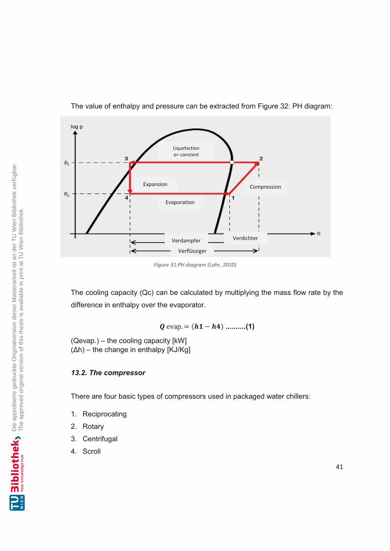
The value of enthalpy and pressure can be extracted from Figure 32: PH diagram:
The cooling capacity (Qc) can be calculated by multiplying the mass flow rate by the
difference in enthalpy over the evaporator.
evap. = ( − ) ..........(1)
(Qevap.) – the cooling capacity [kW] (Δh) – the change in enthalpy [KJ/Kg]
13.2. The compressor
There are four basic types of compressors used in packaged water chillers:
1. Reciprocating
2. Rotary
3. Centrifugal
4. Scroll
Figure 31:PH diagram (Lohr, 2010)
Specific Humidity
Liquefaction p= constant
Compression Expansion
Evaporation
Verdampfer Verdichter Verflüssiger

42
The type of compressor chosen for this unit is the hermetic scroll compressor. Thus,
the only refrigerant permitted for these compressors is R-407C. The reciprocating and
scroll compressors are widely used in tonnage ranges chillers, where the compressor
design is usually a hermetic compressor. Scroll compressors have largely taken over
this market. Capacity modulation is achieved through the staging of multiple
compressors that are grouped (piped in parallel) in several circuits, which creates
fewer redundancies in case of a compressor fail. In addition, as positive displacement
machines, they retain near full cooling capacity, and are, therefore, highly suitable for
air-cooled applications, and to be used as heat recovery machines. “Control is
achieved by stepping unloaders and cycling compressors on/off, which creates a
choppy part-load performance curve” (energydesign, 2009)a. Scroll chillers tend to be
low first-cost machines. Inside the compressor, the refrigerant vapor is compressed
from the evaporation pressure to condensation pressure. “Scroll compressors are
unidirectional, and refrigerant compression is only ensured when the phase order is
followed” (Carrier, 2017)d. The power input to the refrigerant is calculated with the
enthalpy change over the compressor.
. = ( − ) ..........(2)
(wcomp) – the work done to drive the compressor [kJ/kg] (Δh) – the change in enthalpy [KJ/Kg]
13.3. The condenser “There are a number of different kinds of condensers manufactured for the packaged
water chiller. These include water-cooled, air-cooled, and evaporative-cooled
condensers” (Roy, 2015)b.
Inside the condenser, the refrigerant condenses when the heat rejects during the heat
transfer. Consequently, the enthalpy of the refrigerant decreases. In most heat pump
applications, the refrigerant is being subcooled. The heating reject (Qcond) of the
chiller can be calculated using the formula presented below:
. = ∗ ( − ) ..........(3)
43
(Qcond) – the heat rejected by the condenser [kJ/kg] (Δh) – the change in enthalpy [KJ/Kg]
13.4. The expansion valve
The purpose of the expansion valve is to reduce the pressure and temperature of the
refrigerant to achieve the liquid and gaseous state of the refrigerant when it enters the
evaporator.
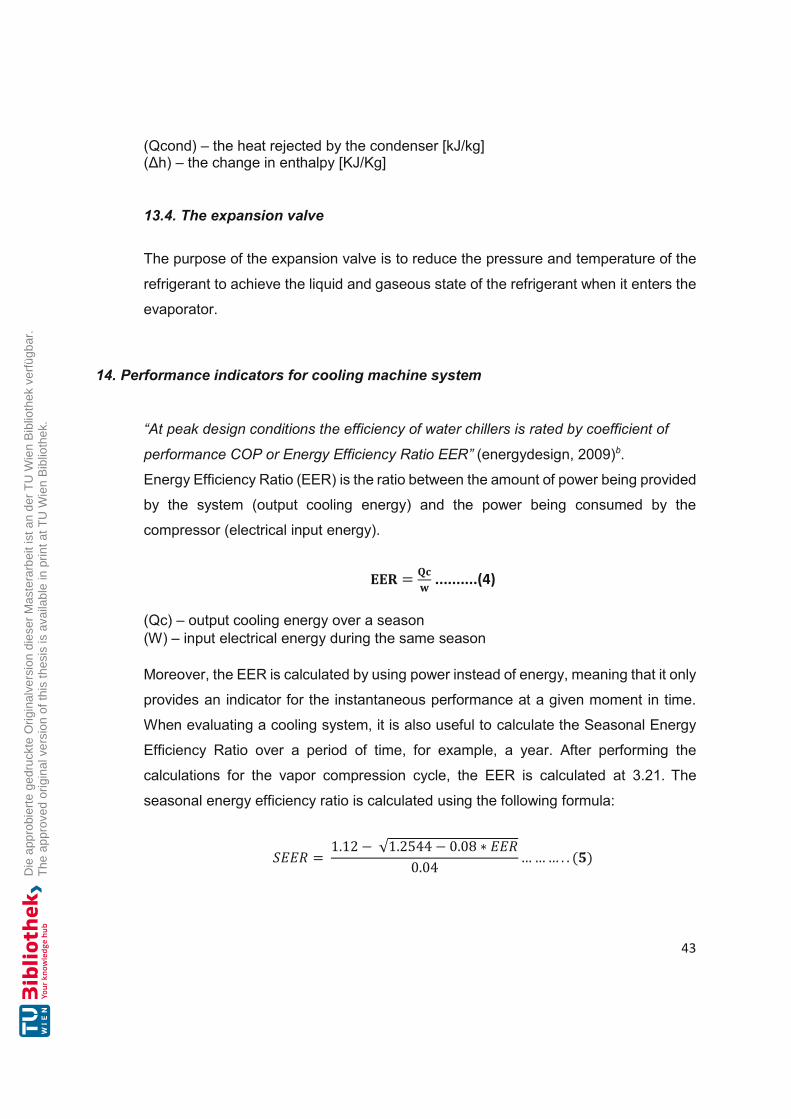
14. Performance indicators for cooling machine system
“At peak design conditions the efficiency of water chillers is rated by coefficient of
performance COP or Energy Efficiency Ratio EER” (energydesign, 2009)b.
Energy Efficiency Ratio (EER) is the ratio between the amount of power being provided
by the system (output cooling energy) and the power being consumed by the
compressor (electrical input energy).
= ..........(4) (Qc) – output cooling energy over a season (W) – input electrical energy during the same season Moreover, the EER is calculated by using power instead of energy, meaning that it only
provides an indicator for the instantaneous performance at a given moment in time.
When evaluating a cooling system, it is also useful to calculate the Seasonal Energy
Efficiency Ratio over a period of time, for example, a year. After performing the
calculations for the vapor compression cycle, the EER is calculated at 3.21. The
seasonal energy efficiency ratio is calculated using the following formula:
= 1.12 − √1.2544 − 0.08 ∗0.04 … … … . . ( )

44
The ESEER (European Seasonal Energy Efficiency Ratio) is used to describe the
energy efficiency of a refrigeration machine over one year period, which is calculated
as the ratio of the accumulated useful energy (cooling) divided by the amount of
accumulated consumed energy (electricity) over a certain period of time, usually on a
yearly basis.
“The ESEER is calculated by combining full and part load operating Energy Efficiency
Ratios (EER), for different seasonal air or water temperatures, and including for
appropriate weighting factors” (JSTOR, 2011)a.
These values are shown in the following table:
Table 2: The values air, water temperatures of ESEER (JSTOR, 2011)b Partial load
ratio Air temperature (oC) Water temperature
(oC) Weighting
coefficients 100 35 30 3% 75 30 26 33% 50 25 22 41% 25 20 18 23%
The formula for ESEER can then be presented as follows, where a, b, c & d are the
load profile weighting factors relevant to the proposed application:
ESEER = a(EER@100% load × 0.03) + b(EER@75% load × 0.33) + c(EER@50%
load × 0.41) + d(EER@25% load × 0.23) ..........(6) (Y. SAHEB, 2005)
15. Simulation of different variants on cooling systems
All variants were calculated based on a selected maximum cooling capacity of 275
kWc to enable a comparison of the variants. After system design, 4 variants of
simulation of the cooling system were analysed and are presented in the following
section.

45
1. Variant: represents the design variant according to the system scheme. A
groundwater temperature of 11.5°C and one result in cooling temperatures on the
secondary side (floor pipes) of 16 °C/22°C. The design point of the central, speed-
controlled circulation pump is 18.33 kg / s. The groundwater requirement of approx.
14.06 kg/s (210 kWc free cooling and the rest of 65 kWc using a refrigeration
machine including water cooling) would be below the consensus water volume of
18.33 kg/s (66 m3/h). The cold for free cooling could be 100% covered by
groundwater according to the scheme. Moreover, a separating heat exchanger is
amply designed for this process with 310 kW. No deficiencies were found in the
design.
2. Variant: the groundwater temperature is raised to 15.5°C, and the flow
temperature of the underfloor cooling rises to 20°C. In principle, the water in the
pipes can only be circulated without achieving the necessary cooling capacity,
which are considerably below the 20-25 W/m2 according to the design. It can be
seen here that the chiller cannot cover the entire refrigeration requirement of 275
kWc. However, the groundwater could be used for the condenser cooling of the
chiller, that would prevent the air cooler from being overloaded at high outside
temperatures. The water re-cooling would be the only useful function in the use of
groundwater. If necessary, it should be checked whether the condenser pressure
of the refrigeration machine can be reduced further by lowering the return to the
cooler below 40°C and thus reducing the power requirement. Moreover, 45 °C
saturation temperatures appear to be quite high when using groundwater.
3. Variant: the refrigeration machine works at full load with 216 kWc and with the heat
dissipation through the water cooler with 15.5 / 19.5°C groundwater extraction and
groundwater infiltration temperature. This operational case would only be approved
for 4 weeks according to the notification. The simulation with the approved
infiltration temperature was carried out. Unfortunately, the water/water cooler alone
does not provide cooling, because the consensus water quantity is exceeded.
4. Variant: the refrigeration machine works at full load with 216 kWc and with the heat
dissipation through the air cooler. It can be seen that at an outside temperature of
32°C, the limit of the cooler has been reached. Hence, a mixed cooling of water re-
cooling and air cooling is necessary at higher outside temperatures.

46
16. Presentation of results
In a model of this study, the dew point is monitored and for each floor circle and room,
a humidity sensor is installed. The cooling requirement of the property is 275 kWc,
based on the design outside temperature of 35°C. However, since tthe chiller could
only deliver a maximum of 216 kWc, the rest of the cooling capacity comes from free
cooling. Furthermore, the groundwater temperature for cooling was assumed at 11.5
°C, at which temperature, a floor pipe temperature of 16 °C could be achieved and free
cooling would be effective. The evaluation of the original system of groundwater design
and dimensions shows there is a difference between design data and actual operating
data for the well/groundwater cooling.
The groundwater temperatures are up to approx. 16.6°C. According to the authorities
(Team Hydrography MA 45/ Vienna the temperature of groundwater is measured in
the closest measuring point between 2016 and mid-2019), the temperature of the
groundwater body, which is located about 1.7 km northwest of the requested property,
is measured between 14.3°C in winter and 16.6°C in summer.
According to Municipal Department 58 / Water Law Vienna decision, the maximum
groundwater withdrawal quantities are 18.5 l/s or 1,600 m3 per day or 250,000 m3/a
for the operation of the water/water cooling pump. Due to the high groundwater
temperature and the degree of the temperature of the heat exchanger and other
temperature losses between the extraction point and floor distributor, the water
temperature in the floor pipes flow is at 20-22°C. At such a high temperature, the floor
cooling, where the cold transmission happens through radiation, is no longer effective
and does not correspond to the agreed quality.
It was found using the design of the cooling system that the design point according to
the scheme of the system is directly outside the operating range at a design
temperature of 35°C. Since the chiller could only deliver a maximum of 216 kWc, if it
fails in well cooling due to the high groundwater temperature, the chiller does not cover
the missing capacity. Therefore, refrigeration machine is neither suitable to take over
the additional, nor to cover the total cooling demand.

47
17. Calculation
In addition to planed operating costs, there is an added electricity demand and the
increase in maintenance costs due to higher operating hours, as the chiller machine
must also take over the free cooling portion. The higher electricity demand, due to the
increased operation of the refrigeration machine, was calculated in a simulation
calculation (difference in internal electrical demand between Variant 1 and Variant 3)
and amounts to approximately 67 kWe - 20 kWe = 47 kWe. Given 800 full load hours
for cooling, calculated over a technical service life of the system of 20 years and a
mixed electricity price of 20 cents / kWh, additional costs of (67 kWe-20 kWe) x 800 h
/a x 20 a x 0.2 EUR / kWhe are at EUR 150,400 without interest.
Because of the increased use of the refrigeration machine, a rise in maintenance costs
can also be assumed. The maintenance of refrigeration and air conditioning
components is necessary to assure the functionality and safety of the systems, making
maintenance an essential part of the operation. Furthermore, tthe maintenance costs
of a refrigeration machine are around 2% of the investment costs per year. Assuming
costs of EUR 450/kWc x 210 kWc= 94,500 EUR, maintenance costs of EUR 1,890 per
year are calculated. Due to the otherwise lower operating hours, only 1/3 of the costs
would be incurred per year. Thus, estimated over 20 years it results in 1,890 EUR / a
x 2/3 x 20a = 25200 EUR additional costs for maintenance of the refrigeration machine
without interest. The total additional costs from the title of operating costs and
maintenance costs without interest thus amount to EUR 150,400 + EUR 25,200 = EUR
175,600 EUR.
The Feed-In Tarif is 0.035 (€/KWh) (Schröder, 2009), Full Load Hours of chiller 800
(h/year), Discount rate 5 (%/year), Electricity price 0.077 (€/kWhe) (Energie, 2021),
and the investment horizon for the investment project has calculated 20 years.

48
Table 3: Financial Parameters Financial Parameters: Cooling capacity Discount rate (r)
210 KWc 5 %/year
Investment cost 94,500 € Feed-In Tarif (FIT) 0.035 € electricity price FLH
0.077 €/kWhe 800 h/year
Real escalation costs of O&M 2 %/year Investment Horizon (T) 20 year Seasonal Energy Efficiency Ratio (SEER)
3.03
Annual cooling energy output 168,000 KWh/year Operation & maintenance (O&M) 1,890 €/year Investment/ Replacement t=10 Capital Recovery Factor (CRF)
11,340 € 0.08
The annual cost operate unite 800 h/year x 47 KWe x 0.077 = 2,895 €/year.
The annual cooling sale 210 KWc x 800 h/year x 3.03 x 0.035 = 17,816 €/year.
Table 4: Financial calculation of project

49
The net present value of (NPV) 56,220 € is calculated.
The capital recovery of factor CRF = ∗( )( ) ..........(7) → 0.08
Thus, the cost annuity is a = NPV * ∗( )( ) ..........(8) → 4508.83 €
Sensitivity of the Annuity to Variation of O&M Costs
With the increase of percent range, the overall costs of the operation rise, which results
in the increase of generation costs, resulting in a rise that is above Feed-In Tariff,
making it a bad investment.
Table 5: Sensitivity of the Annuity
Var. O&M Annuity -10% 1701 3009 -9% 1720 3159 -8% 1739 3309 -7% 1758 3459 -6% 1777 3609 -5% 1796 3759 -4% 1814 3909 -3% 1833 4059 -2% 1852 4209 -1% 1871 4359 0% 1890 4509 1% 1909 4659 2% 1928 4809 3% 1947 4959 4% 1966 5109 5% 1985 5259 6% 2003 5409 7% 2022 5559 8% 2041 5709 9% 2060 5859 10% 2079 6009

50
18. Conclusion
Floor cooling is generally only suitable for low cooling loads. At 11.5°C the groundwater
temperature could have been expected at 18 to 20 W/m2 of cooling load. According to
the planner, these loads were appropriate, however, at temperatures above 16°C, the
cooling capacity of groundwater decreases considerably. Therefore, at high
temperatures the groundwater is almost ineffective for floor cooling, and in this case
could only be seen as relieving the air cooling from the water cooler. This reduces the
air cooler's own electrical consumption by approx. 12 kWhe per MWh, hence, less heat
dissipates in the air cooler. It should be checked during a test run whether the
condenser inlet temperature can be reduced below 40°C. This would reduce the
condensing pressure of the refrigerant and, as a result, the power requirement of the
compressor would also decrease.
It should be noted that when using cooling by water cooling floors where the cooling
water is too low, then the floor gets slippery because the humidity of the air starts
condensing. The condensation occurs when the warm, moist air from the room meets
the colder surface of the heat exchanger (evaporator). Moreover, the air temperature
unexpectedly drops when it gets in touch with the less warm floor, reducing the quantity
of moisture it can normally hold. This results in moisture formation of condensation.
Figure 32: Sensitivity Analysis

51
In case of failure of the well cooling and in accordance with the data presented above,
the refrigeration machine (without free cooling with groundwater) with a maximum
cooling capacity of 216 kWc cannot take over the additional cooling load of, in total
275 kWc, to cover the total cooling requirements of the property, floor cooling and fan
coils. Thus, the system would have to be dimensioned 30% larger. In mathematical
terms, the groundwater cooling would take approximately 2/3 of the cooling
requirements, and the rest should be accounted for by the cooling machine. Hence,
groundwater cooling would be more economical than the operation of a refrigeration
machine.
It can be concluded that using ceiling cooling by means of free cooling for buildings is
better and more effective than cooling by floor cooling, as it dissipates high cooling
loads. Ceiling cooling offers great design freedom and more comfort, as they have no
flow noises compared to conventional ventilation, which increases the thermal comfort
in a room.
52
Bibliography: Books:
Givoni Baruch (1994): Passive and low energy cooling of buildings. John Wiley and Sons, New York
Glück H. Bernd (1999): Thermische Bauteilaktivierung. C. F. Müller Verlag, Heidelberg
Kim Y. et al. (2016): Hybrid ground-source heat pump systems. In: Advances in Ground-Source Heat Pump Systems. pp. 331-357
Lieberman N. /Norman P. /Elizabeth T. (2014): A Working Guide to Process Equipment. 3rd Edition, Mc-Graw-Hill, New York
Shrestha Nirendra L./Oppelt Thomas/ Rudolf Verena/ Thorsten Urbaneck. (2017): Advanced Technical Concepts for Low-Exergy Climate and Cooling Distribution. In: Advanced Concepts for Renewable Energy Supply of Data Centres. River Publishers, Denmark, pp. 103-138
U. Dentel Dietrich A. (2006): Komfort/ Thermische Behaglichkeit – Komfort in Gebäuden. HCU Hafen City Universität, Hamburg
Conference Proceedings:
Ketfi Omar/ Merzouk Mustapha/ Kasbadji Nachida M. (2015): Performance of a Single Effect Solar Absorption Cooling System (Libr-H2O). In: International Conference on Technologies and Materials for Renewable Energy, Environment and Sustainability, pp. 130-138, Energy Procedia, TMREES15
Saheb Y/ Becirspahic S/ Simon J. (2005): Effect of the Certification on Chillers Energy. In : Effect of the Certification on Chillers Energy Efficiency - Building Performance Congress
Sanchez Carmen G. / Nagore Del Campo Urrutia / Neila Javier (2011): Earth to air heat exchanger conditioning potential in an office building in a continental mediterranean climate. In: International Conference on Electrical and Control Engineering. Yichang, IEEE Institute of Electrical Engineers, pp. 2205-2208
Tu Zhiyuan / Peng Fusheng / Wang Jie / Huang Chunjie (2020): Optimizing Energy Consumption Strategy of Water-loop Heat Pump. In: International Workshop on Renewable Energy and Development (IWRED 2020), China, DOI:10.1088/1755-1315/510/2/022002
Willemsen B. / Drijver A. (2018): GROUNDWATER AS A HEAT SOURCE FOR GEOTHERMAL HEAT PUMPS. In: International Course on GEOTHERMAL HEAT PUMPS. The Netherlands, pp. 156-166
Journal Articles:
Chen Xinwen / Li Zhao / Li Zhaohua, et.al. (2019): Modelling of Refrigerant Distribution in an Oil-Free Refrigeration System using R134a. In: Energies. 12 (24)
53
Ghernaout M. El-Amine / Meghelli Abdelkarim (2013): Approach to Choice Method of Aid. In: European Scientific Journal. 9
Gschwend A. / Menzi T. / Caskey S. et.al. (2016): Energy consumption of cold climate heat pumps in different climates – Comparison of single-stage and two-stage systems. In: International Journal of Refrigeration. 62, pp. 193-206
Imal Muharrem / Yılmaz Koray / Pınarbaşı Ahmet (2015): Energy Efficiency Evaluation and Economic Feasibility Analysis of a Geothermal Heating and Cooling System with a Vapor-Compression Chiller. In: Sustainability. 7 (9), pp. 12926--12946
Kolhekar Rucha R. / Kale N.W. (2020): Review on Passive cooling Techniques using Phase Change. In: IOSR Journal of Engineering. 10 (1), pp. 33-42
Niemann J. / Bean J. / Avelar V. (2011): Economizer modes of data center cooling systems. In: Schneider Electric Data Center Science Center Whitepaper. 160
Rambo J. / Joshi Y. (2006): Convective transport processes in data centers. In: Numerical Heat Transfer 49, Part A.
Sharma V.K. / Marano D. / Anyanwu C.N. et al. (2010): Solar Cooling: A Potential Option for Energy Saving and Abatement of Greenhouse Gas Emissions in Africa. In: Singapore Journal of Scientific Research. 1, pp. 1-12
Treberspurg Martin / Djalili Mariam (2011): Solar Heating & Cooling. In: Sci-Network Sustainable Construction & Innovation through Procurement. pp. 1-16
Velraj R. / Geetha N.B. (2012): Passive cooling methods for energy efficient buildings with and without thermal energy storage - A review. In: Energy Science and Research. 29, pp. 913-946
Xuan Y.M. / Xiao F. / Niu X.F. et.al. (2012): Research and application of evaporative cooling in China. In : Renewable and Sustainable Energy. 16 (5), 3523-3534
Z. Ud Din A. Waqas (2013): Renewable and Sustainable Energy Reviews. 18. Islamabad, Pakistan
Zhang et.al. (2014): Free cooling of data centers. In: Renewable and Sustainable Energy Reviews. 35, pp. 171–182
Internet Sources:
ARANER The Vapor Compression Refrigeration Cycle, Step By Step [Online]. - araner, 2021. - https://www.araner.com.
ARANER (2021): The Vapor Compression Refrigeration Cycle, Step By Step. [Online]. - araner, 2021. - https://www.araner.com/blog/vapor-compression-refrigeration-cycle - retrieved on May 11, 2021https://www.araner.com.
ARANER The Vapor Compression Refrigeration Cycle, Step By Step [Online]. - araner, 2021. - https://www.araner.com.

54
Bott Andrew (2016): Taking effective control of ventilation. https://modbs.co.uk/news/fullstory.php/aid/15972/Taking_effective_control__of_ventilation.html - retrieved on May 11, 2021
Carrier (2003): Water-Cooled/Condenserless Liquid Chillers. https://t1p.de/wu90 - retrieved on May 11, 2021
Carrier (2017): 30RW/RWA Water-Cooled/Condenserless Liquid Chillers with Integrated Hydronic Modules. https://t1p.de/ulqt - retrieved on May 11, 2021
Carrier (2021): Heat Pumps vs. Air Conditioners. https://www.carrier.com/residential/en/us/products/heat-pumps/heat-pumps-vs-air-conditioners/ - retrieved on May 11, 2021
Delmastro C. / Abergel T. (2020): Is cooling the future of heating? https://www.iea.org/commentaries/is-cooling-the-future-of-heating - retrieved on May 11, 2021
Dwyer Tim (2017): Module 108: Applying plate heat exchangers to integrate high-efficiency boilers into legacy systems. https://www.cibsejournal.com/cpd/modules/2017-02-xch/ - retrieved on May 11, 2021
Encyclopaedia Britannica (2018): Solar heating. https://www.britannica.com/technology/solar-heating - retrieved on May 11, 2021
Engineering Bright Hub (2009): HVAC: Heating, Ventilation & Air-Conditioning. https://www.brighthubengineering.com/hvac/ - retrieved on May 11, 2021
Evapco (2017): Eco-Air Series Flat Industrial Air Cooled Condenser. https://www.evapco.com/products/condensers-air-cooled/eco-air-series-flat-industrial-air-cooled-condenser - retrieved on May 12, 2021
Garrity Katie (2020): The Greenhouse Effect Is What Makes Earth the Perfect Place for Humans. https://www.greenmatters.com/p/what-is-the-greenhouse-effect - retrieved on May 12, 2021
Giz Powering Agriculture (2018): Implications of natural refrigerants for cooling technologies - Converting from HFCs/HCFCs to natural refrigerants. https://energypedia.info/wiki/Implications_of_natural_refrigerants_for_cooling_technologies - retrieved on May 12, 2021
Greenhouse Gases (2009): Greenhouse Gas Emissions. https://www.epa.gov/ghgemissions - retrieved on May 12, 2021
Heat Pump Masters (2015): Types of Heat Pumps. https://www.heatpump.org.nz/types/ - retrieved on May 12, 2021
Hug Rolf (2009): Cooling with Solar Heat. https://tamilnadusolarpower.blogspot.com - retrieved on May 12, 2021

55
IEA (2020): Renewable Energy Policies in a Time of Transition: Heating and Cooling. https://www.iea.org/reports/renewable-energy-policies-in-a-time-of-transition-heating-and-cooling - retrieved on May 12, 2021
Jones P. / Beanland B. (2019): Opening the loop – CP3 guide. https://www.cibsejournal.com/technical/opening-the-loop-cp3-guide/ - retrieved on May 11, 2021
Lohr Hans-Joachim (2010): Log p –h -Diagramm. In: Wärmepumpen + Kälteanlagen Energiemanager IHK. https://docplayer.org/13383939-Waermepumpen-kaelteanlagen-energiemanager-ihk.html - retrieved on May 12, 2021
Merrett Neil (2019): Toshiba VRF innovation targets high temperature water heating. https://www.racplus.com/news/toshiba-vrf-innovation-targets-high-temperature-water-heating-04-07-2019/ - retrieved on May 12, 2021
Peterson K. / Boulanger J. (2018): Cooling Systems and Thermal Energy Storage. https://www.appa.org/bok/cooling-systems-and-thermal-energy-storage/ retrieved on May 11, 2021
Resources Energy (2009): Design Air conditioning, cooling, ventilation, air infiltration, Energy sources, district heating / cooling, cogeneration. In: Energy Design Resources program
Sabiatech (2015): Geblaesekonvektoren & Torluftschleier https://www.sabiatech.at/energietechnik/ - retrieved on May 12, 2021
Sayan Roy (2015): Study Performance Analysis of Chilling Plant. https://www.slideshare.net/SayanRoy32/reportchillerby-sayan-roy - retrieved on May 12, 2021
Schröder Dietrich (2009): Energieverbrauch und Energiekosten von Kühldecken. https://docplayer.org/18026791-Energieverbrauch-und-energiekosten-von-kuehldecken.html - retrieved on May 12, 2021
SHC (2020): Solar Heating & Cooling Overview. https://www.iea-shc.org/solar-heating-cooling - retrieved on May 12, 2021
Taylor Engeneering (2009): Chilled Water Plant Design Guide https://t1p.de/qyh1 - retrieved on May 11, 2021
TechDev (2020): Solar air conditioning. https://www.energy-without-carbon.org/SolarAirConditioning - retrieved on May 12, 2021
Verma S.S. (2015): Solar-Assisted Cooling And Air-Conditioning. https://www.coolingindia.in/solar-assisted-cooling-and-air-conditioning/ - retrieved on May 12, 2021
Viñolo Ida (2020): How does a furnace and air conditioner work together. https://askinglot.com/how-does-a-furnace-and-air-conditioner-work-together - retrieved on May 12, 2021

56
Washington Energy (2021): AC vs Heat Pump: The Cooling Battle! https://www.washingtonenergy.com/idea-center/ac-vs-heat-pump-battle-cooling/ - retrieved on May 11, 2021
WAZIPOINT (2018): Condenser of Centrifugal Water Chiller. https://www.wazipoint.com/2018/09/condenser-of-centrifugal-water-chiller.html - retrieved on May 12, 2021
Weiss W. (2019): Module 3: Solar Energy – Solar Heating & Cooling. AEE INTEC, Graz - retrieved on May 12, 2021
Wien Energy (2021): Energie Wien Strom. https://www.wienenergie.at - retrieved on May 11, 2021
Wikipedia (2011): European seasonal energy efficiency ratio. https://en.wikipedia.org/wiki/European_seasonal_energy_efficiency_ratio - retrieved on May 12, 2021
Withouse John (2018): HVACR Tech Tip: A Psychrometrics Reminder for the HVACR Technician. http://blog.parker.com/hvacr-tech-tip-a-psychrometrics-reminder-for-the-hvacr-technician - retrieved on May 12, 2021
Witt M. (2018): Natürliche Kältemittel. https://secon-gmbh.com/kaltwassersaetze/natuerliche-kaeltemittel/ - retrieved on May 12, 2021

57
Abbreviations
€ Euro °C Celsius a Year CFCs Chlorofluorocarbons CH4 Methane CO2 Carbon Dioxide COP Coefficient of Performance CRF Capital Recovery Factor db Dry bulb DP Dew point E Electricity ESEER European Seasonal Energy Efficiency Ratio F-gas Fluorinated gases FIT Feed In Tarif FLH Full Load Hour GHG Greenhause Gases GHP Geothermal Heat Pump GLHE Ground Loop Heat Exchanger GSHP Ground Source Heat Pump GWP Global Warming Potential h Hour HCFC Hydrofluorocarbons HCFCs Halogenated Chlorofluorocarbons HFC Hydrofluorocarbon HVAC Heat Ventilation Air Conditioning K Kelvin KJ/Kg Kilo Joule per Kilogram KVS Constant Volume System kWc Cooling Capacity kWe Kilo Watt Electricity KWh Kilo Watt hour L Liquid MWh Megawatt hour N2O Nitrous Oxide NPV Net Present Value O&M Operation & Maintance ODP Ozone Depletion Potential P Pressure PFCs Perfluorocarbons PH Pressure and enthalpy Q evap Heat absorbed by the evaporator Qab Heat reject Qc Cooling capacity Qcond Heat reject by condenser Qh Heating Capacity Qzu Heat Add

58
RW Type of Carrier chiller S Entropy SEER Seasonal Energy Efficiency Ratio SF6 Sulfur Hexafluoride V Vapour VRF Variable Refrigerant Flow VVS Variable Volume Flow w comp Work done to drive the compressor WLHP Water loop heat pump systems Δh Change in enthalpy EER Energy efficincy ratio

59
List of Figures Figure 1: Global Warming Potential (Witt, 2012) ................................................................... 4 Figure 2: Overview of refrigerants (GIZ, 2018) ...................................................................... 5 Figure 3: Greenhause Gas Emission (EPA, 2009)c .............................................................. 6 Figure 4:Classification of passive cooling techniques for building applications. (Givoni, 1994)a ................................................................................................................................... 8 Figure 5:Schematic diagram of direct airside free cooling (J Niemann, 2011 p. 132) .......... 11 Figure 6: Shell-and-tube heat exchanger (N. Lieberman, 2014) .......................................... 12 Figure 7:Principle of the open groundwater system (Willemsen, 2018) ............................... 13 Figure 8:Central air conditioning (Bott, 2016) ...................................................................... 15 Figure 9: Fan coil unit (left) and door air curtain device (right) (Sabiatech) .......................... 16 Figure 10: Air-only system, single-channel system Source: VDI Lexicon ............................ 16 Figure 11:Induction system air/water ................................................................................... 18 Figure 12:Fan coil air/water ................................................................................................. 18 Figure 13: VRF system (MERRETT, 2019) ......................................................................... 19 Figure 14:VRV Multisplit System (Nelson, 2021) ................................................................. 20 Figure 15: Solar-Assisted Cooling And Air-Conditioning (S.S.Verma, 2015)b ...................... 23 Figure 16: Absorption chiller (Ketfi, 2015) ........................................................................... 25 Figure 17:Main components of the system at the University Clinic of Freiburg: Adsorption refrigeration machine (left) and solar thermal system (right) (Weiss, 2019 p. 146/186) ....... 25 Figure 18:Single-stage electric chiller (ARANER, 2021) ...................................................... 26 Figure 19:Schematic of a typical GSHP system (Y.Kim, 2016 pp. 331-357) ........................ 27 Figure 20:Schematic of a WLHP system with water-to-water (Z. Tu, et al., 2020 ) .............. 28 Figure 21:Extraction and reinjection of groundwater (Beanland, 2019) ............................... 30 Figure 22:Electric refrigeration machine (X. Chen, et al., 2019) .......................................... 30 Figure 23:Separation heat exchanger (Dwyer, February 2017) ........................................... 31 Figure 24:Air heat exchanger (GOODTOWER, 2021) ......................................................... 32 Figure 25:Cooling water heat exchanger (WAZIPOINT, 2018) ............................................ 32 Figure 26: Comfort room area air humidity - room air temperature according to Frank ........ 33 Figure 27: Cooling and dehumidification (Withouse, 2018) ................................................. 34 Figure 28: Diagram for moist air .......................................................................................... 36 Figure 29:Operating range of the chiller (Carrier, 2017)a ..................................................... 38 Figure 30:capacity cooling output of the Chiller (Carrier, 2017)b .......................................... 38 Figure 31:Pressure-Enthalpy chart, R407c cycle (Carrier, 2017)c........................................ 39 Figure 32:PH diagram (Lohr, 2010) ..................................................................................... 41 Figure 33: Sensitivity Analysis ............................................................................................. 50

60
List of Tables Table 1: Montreal protocol (Resources, 2009) ...................................................................... 3 Table 2: The values air, water temperatures of ESEER (JSTOR, 2011)b ............................ 44 Table 3: Financial Parameters ............................................................................................ 48 Table 4: Financial calculation of project............................................................................... 48 Table 5: Sensitivity of the Annuity ....................................................................................... 49