floor plan symbols project directory scope of work
TRANSCRIPT
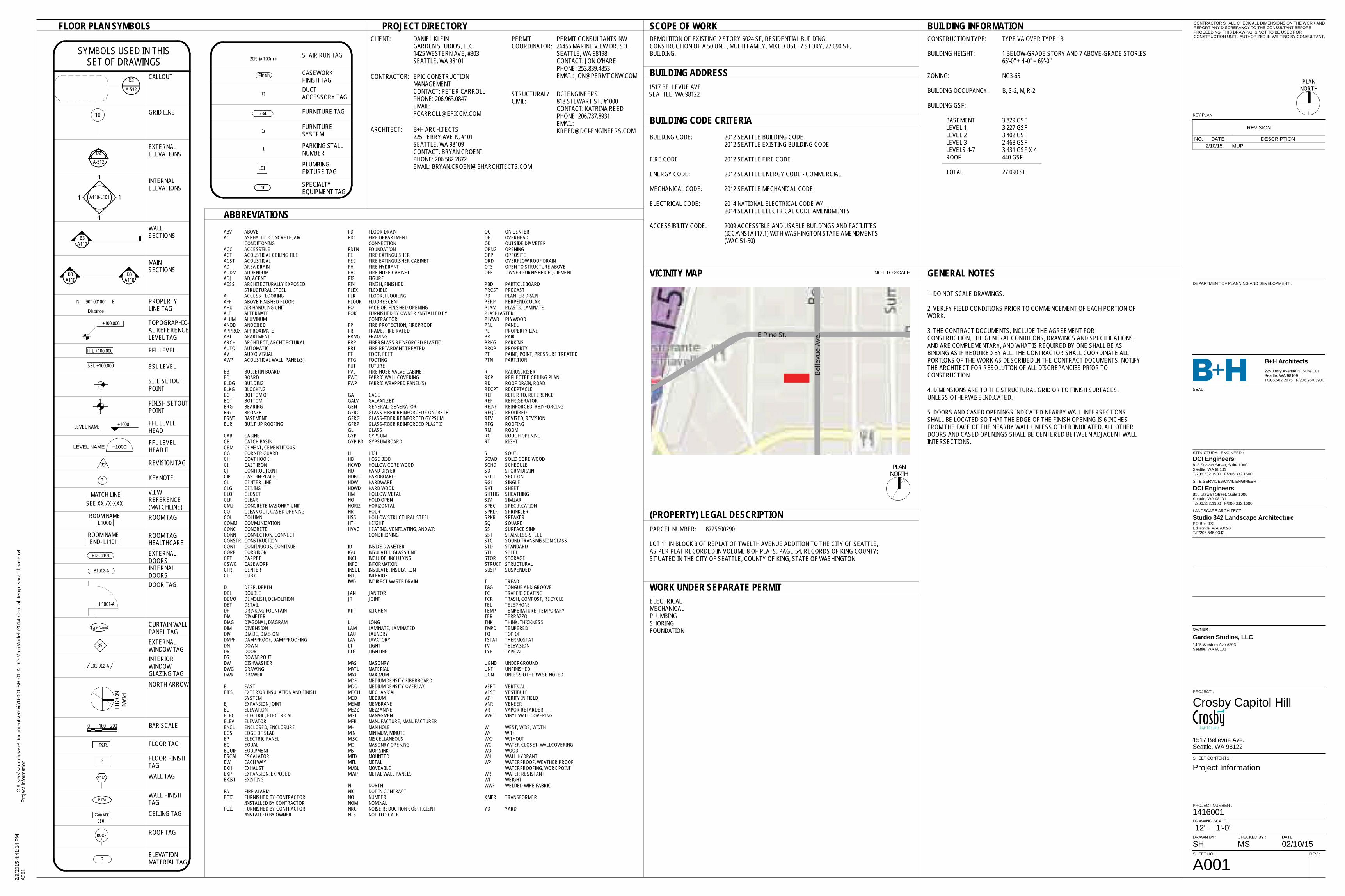
FLOOR PLAN SYMBOLS
ABBREVIATIONSABV ABOVEAC ASPHALTIC CONCRETE, AIR
CONDITIONINGACC ACCESSIBLEACT ACOUSTICAL CEILING TILEACST ACOUSTICALAD AREA DRAINADDM ADDENDUMADJ ADJACENTAESS ARCHITECTURALLY EXPOSED
STRUCTURAL STEELAF ACCESS FLOORINGAFF ABOVE FINISHED FLOORAHU AIR HANDLING UNITALT ALTERNATEALUM ALUMINUMANOD ANODIZEDAPPROX APPROXIMATEAPT APARTMENTARCH ARCHITECT, ARCHITECTURALAUTO AUTOMATICAV AUDIO VISUALAWP ACOUSTICAL WALL PANEL(S)
BB BULLETIN BOARDBD BOARDBLDG BUILDINGBLKG BLOCKINGBO BOTTOM OFBOT BOTTOMBRG BEARINGBRZ BRONZEBSMT BASEMENTBUR BUILT UP ROOFING
CAB CABINETCB CATCH BASINCEM CEMENT, CEMENTITIOUSCG CORNER GUARDCH COAT HOOKCI CAST IRONCJ CONTROL JOINTCIP CAST-IN-PLACECL CENTER LINECLG CEILINGCLO CLOSETCLR CLEARCMU CONCRETE MASONRY UNITCO CLEAN OUT, CASED OPENINGCOL COLUMNCOMM COMMUNICATIONCONC CONCRETECONN CONNECTION, CONNECTCONSTR CONSTRUCTIONCONT CONTINUOUS, CONTINUECORR CORRIDORCPT CARPETCSWK CASEWORKCTR CENTERCU CUBIC
D DEEP, DEPTHDBL DOUBLEDEMO DEMOLISH, DEMOLITIONDET DETAILDF DRINKING FOUNTAINDIA DIAMETERDIAG DIAGONAL, DIAGRAMDIM DIMENSIONDIV DIVIDE, DIVISIONDMPF DAMPPROOF, DAMPPROOFINGDN DOWNDR DOORDS DOWNSPOUTDW DISHWASHERDWG DRAWINGDWR DRAWER
E EASTEIFS EXTERIOR INSULATION AND FINISH
SYSTEMEJ EXPANSION JOINTEL ELEVATIONELEC ELECTRIC, ELECTRICALELEV ELEVATORENCL ENCLOSED, ENCLOSUREEOS EDGE OF SLABEP ELECTRIC PANELEQ EQUALEQUIP EQUIPMENTESCAL ESCALATOREW EACH WAYEXH EXHAUSTEXP EXPANSION, EXPOSEDEXIST EXISTING
FA FIRE ALARMFCIC FURNISHED BY CONTRACTOR
/INSTALLED BY CONTRACTORFCIO FURNISHED BY CONTRACTOR
/INSTALLED BY OWNER
OC ON CENTEROH OVERHEADOD OUTSIDE DIAMETEROPNG OPENINGOPP OPPOSITEORD OVERFLOW ROOF DRAINOTS OPEN TO STRUCTURE ABOVEOFE OWNER FURNISHED EQUIPMENT
PBD PARTICLEBOARDPRCST PRECASTPD PLANTER DRAINPERP PERPENDICULARPLAM PLASTIC LAMINATEPLASPLASTERPLYWD PLYWOODPNL PANELPL PROPERTY LINEPR PAIRPRKG PARKINGPROP PROPERTYPT PAINT, POINT, PRESSURE TREATEDPTN PARTITION
R RADIUS, RISERRCP REFLECTED CEILING PLANRD ROOF DRAIN, ROADRECPT RECEPTACLEREF REFER TO, REFERENCEREF REFRIGERATORREINF REINFORCED, REINFORCINGREQD REQUIREDREV REVISED, REVISIONRFG ROOFINGRM ROOMRO ROUGH OPENINGRT RIGHT
S SOUTHSCWD SOLID CORE WOODSCHD SCHEDULESD STORM DRAINSECT SECTIONSGL SINGLESHT SHEETSHTHG SHEATHINGSIM SIMILARSPEC SPECIFICATIONSPKLR SPRINKLERSPKR SPEAKERSQ SQUARESS SURFACE SINKSST STAINLESS STEELSTC SOUND TRANSMISSION CLASSSTD STANDARDSTL STEELSTOR STORAGESTRUCT STRUCTURALSUSP SUSPENDED
T TREADT&G TONGUE AND GROOVETC TRAFFIC COATINGTCR TRASH, COMPOST, RECYCLE TEL TELEPHONETEMP TEMPERATURE, TEMPORARYTER TERRAZZOTHK THINK, THICKNESSTMPD TEMPEREDTO TOP OFTSTAT THERMOSTATTV TELEVISIONTYP TYPICAL
UGND UNDERGROUNDUNF UNFINISHEDUON UNLESS OTHERWISE NOTED
VERT VERTICALVEST VESTIBULEVIF VERIFY IN FIELDVNR VENEERVR VAPOR RETARDERVWC VINYL WALL COVERING
W WEST, WIDE, WIDTHW/ WITHW/O WITHOUTWC WATER CLOSET, WALLCOVERINGWD WOODWH WALL HYDRANTWP WATERPROOF, WEATHER PROOF,
WATERPROOFING, WORK POINTWR WATER RESISTANTWT WEIGHTWWF WELDED WIRE FABRIC
XMFR TRANSFORMER
YD YARD
PROJECT DIRECTORYCLIENT: DANIEL KLEIN
GARDEN STUDIOS, LLC1425 WESTERN AVE, #303SEATTLE, WA 98101
CONTRACTOR: EPIC CONSTRUCTIONMANAGEMENTCONTACT: PETER CARROLLPHONE: 206.963.0847EMAIL:[email protected]
ARCHITECT: B+H ARCHITECTS225 TERRY AVE N, #101SEATTLE, WA 98109CONTACT: BRYAN CROENIPHONE: 206.582.2872EMAIL: [email protected]
PERMITCOORDINATOR:
PERMIT CONSULTANTS NW26456 MARINE VIEW DR. SO.SEATTLE, WA 98198CONTACT: JON O'HAREPHONE: 253.839.4853EMAIL: [email protected]
BUILDING CODE CRITERIA
GENERAL NOTES
1. DO NOT SCALE DRAWINGS.
2. VERIFY FIELD CONDITIONS PRIOR TO COMMENCEMENT OF EACH PORTION OFWORK.
3. THE CONTRACT DOCUMENTS, INCLUDE THE AGREEMENT FORCONSTRUCTION, THE GENERAL CONDITIONS, DRAWINGS AND SPECIFICATIONS,AND ARE COMPLEMENTARY, AND WHAT IS REQUIRED BY ONE SHALL BE ASBINDING AS IF REQUIRED BY ALL. THE CONTRACTOR SHALL COORDINATE ALLPORTIONS OF THE WORK AS DESCRIBED IN THE CONTRACT DOCUMENTS. NOTIFYTHE ARCHITECT FOR RESOLUTION OF ALL DISCREPANCIES PRIOR TOCONSTRUCTION.
4. DIMENSIONS ARE TO THE STRUCTURAL GRID OR TO FINISH SURFACES,UNLESS OTHERWISE INDICATED.
5. DOORS AND CASED OPENINGS INDICATED NEARBY WALL INTERSECTIONSSHALL BE LOCATED SO THAT THE EDGE OF THE FINISH OPENING IS 6 INCHESFROM THE FACE OF THE NEARBY WALL UNLESS OTHER INDICATED. ALL OTHERDOORS AND CASED OPENINGS SHALL BE CENTERED BETWEEN ADJACENT WALLINTERSECTIONS.
VICINITY MAP
(PROPERTY) LEGAL DESCRIPTION
WORK UNDER SEPARATE PERMIT
BUILDING INFORMATIONCONSTRUCTION TYPE: TYPE VA OVER TYPE 1B
BUILDING HEIGHT: 1 BELOW-GRADE STORY AND 7 ABOVE-GRADE STORIES65'-0" + 4'-0" = 69'-0"
ZONING: NC3-65
BUILDING OCCUPANCY: B, S-2, M, R-2
BUILDING GSF:
BASEMENT 3 829 GSFLEVEL 1 3 227 GSFLEVEL 2 3 402 GSFLEVEL 3 2 468 GSFLEVELS 4-7 3 431 GSF X 4ROOF 440 GSF
TOTAL 27 090 SF
ELECTRICALMECHANICALPLUMBINGSHORINGFOUNDATION
SCOPE OF WORKDEMOLITION OF EXISTING 2 STORY 6024 SF, RESIDENTIAL BUILDING.CONSTRUCTION OF A 50 UNIT, MULTI FAMILY, MIXED USE, 7 STORY, 27 090 SF,BUILDING.
PARCEL NUMBER: 8725600290
LOT 11 IN BLOCK 3 OF REPLAT OF TWELTH AVENUE ADDITION TO THE CITY OF SEATTLE,AS PER PLAT RECORDED IN VOLUME 8 OF PLATS, PAGE 54, RECORDS OF KING COUNTY;SITUATED IN THE CITY OF SEATTLE, COUNTY OF KING, STATE OF WASHINGTON
BUILDING ADDRESS1517 BELLEVUE AVESEATTLE, WA 98122
NOT TO SCALE
SYMBOLS USED IN THISSET OF DRAWINGS
D2
A-512
A110-L101
CALLOUT
EXTERNALELEVATIONS
INTERNALELEVATIONS
WALLSECTIONS
10 GRID LINE
B3A110
B3A110
B3A110
MAINSECTIONS
D2
A-512
1
1
1 1
22
SSL +100.000
FFL +100.000
LEVEL NAME +1000
FFL LEVEL
SSL LEVEL
FFL LEVELHEAD
REVISION TAG
90° 00' 00"
Distance
N E PROPERTYLINE TAG
SITE SETOUTPOINT
+100.000
FINISH SETOUTPOINT
LEVEL NAME +1000FFL LEVELHEAD II
ED-L1101
B1012-A
?
ROOM NAMEL1000
ROOM NAMEEND- L1101
MATCH LINESEE XX / X-XXX
EXTERNALDOORSINTERNALDOORS
KEYNOTE
ROOM TAG
ROOM TAGHEALTHCARE
VIEWREFERENCE(MATCHLINE)
Type Name CURTAIN WALLPANEL TAG
L1001-A
DOOR TAG
P17A
35
L01-012-A
0 100 200
PLANNORTH
WALL TAG
BAR SCALE
NORTH ARROW
FLR.X FLOOR TAG
? FLOOR FINISHTAG
P17AWALL FINISHTAG
EXTERNALWINDOW TAGINTERIORWINDOWGLAZING TAG
CEILING TAG
Finish CASEWORKFINISH TAG
2700 AFFCE01
?ELEVATIONMATERIAL TAG
ROOFX
ROOF TAG
R @20 100mm STAIR RUN TAG
234
1i
1
FURNITURE TAG
FURNITURESYSTEM
PARKING STALLNUMBER
1t DUCTACCESSORY TAG
L01 PLUMBINGFIXTURE TAG
1t SPECIALTYEQUIPMENT TAG
TOPOGRAPHIC-AL REFERENCELEVEL TAG
BUILDING CODE: 2012 SEATTLE BUILDING CODE2012 SEATTLE EXISTING BUILDING CODE
FIRE CODE: 2012 SEATTLE FIRE CODE
ENERGY CODE: 2012 SEATTLE ENERGY CODE - COMMERCIAL
MECHANICAL CODE: 2012 SEATTLE MECHANICAL CODE
ELECTRICAL CODE: 2014 NATIONAL ELECTRICAL CODE W/2014 SEATTLE ELECTRICAL CODE AMENDMENTS
ACCESSIBILITY CODE: 2009 ACCESSIBLE AND USABLE BUILDINGS AND FACILITIES(ICC/ANSI A117.1) WITH WASHINGTON STATE AMENDMENTS(WAC 51-50)
FD FLOOR DRAINFDC FIRE DEPARTMENT
CONNECTIONFDTN FOUNDATIONFE FIRE EXTINGUISHERFEC FIRE EXTINGUISHER CABINETFH FIRE HYDRANTFHC FIRE HOSE CABINETFIG FIGUREFIN FINISH, FINISHEDFLEX FLEXIBLEFLR FLOOR, FLOORINGFLOUR FLUORESCENTFO FACE OF, FINISHED OPENINGFOIC FURNISHED BY OWNER /INSTALLED BY
CONTRACTORFP FIRE PROTECTION, FIREPROOFFR FRAME, FIRE RATEDFRMG FRAMINGFRP FIBERGLASS REINFORCED PLASTICFRT FIRE RETARDANT TREATEDFT FOOT, FEETFTG FOOTINGFUT FUTUREFVC FIRE HOSE VALVE CABINETFWC FABRIC WALL COVERINGFWP FABRIC WRAPPED PANEL(S)
GA GAGEGALV GALVANIZEDGEN GENERAL, GENERATORGFRC GLASS-FIBER REINFORCED CONCRETEGFRG GLASS-FIBER REINFORCED GYPSUMGFRP GLASS-FIBER REINFORCED PLASTICGL GLASSGYP GYPSUMGYP BD GYPSUM BOARD
H HIGHHB HOSE BIBBHCWD HOLLOW CORE WOODHD HAND DRYERHDBD HARDBOARDHDW HARDWAREHDWD HARD WOODHM HOLLOW METALHO HOLD OPENHORIZ HORIZONTALHR HOURHSS HOLLOW STRUCTURAL STEELHT HEIGHTHVAC HEATING, VENTILATING, AND AIR
CONDITIONING
ID INSIDE DIAMETERIGU INSULATED GLASS UNITINCL INCLUDE, INCLUDINGINFO INFORMATIONINSUL INSULATE, INSULATIONINT INTERIORIWD INDIRECT WASTE DRAIN
JAN JANITORJT JOINT
KIT KITCHEN
L LONGLAM LAMINATE, LAMINATEDLAU LAUNDRYLAV LAVATORYLT LIGHTLTG LIGHTING
MAS MASONRYMATL MATERIALMAX MAXIMUMMDF MEDIUM DENSITY FIBERBOARDMDO MEDIUM DENSITY OVERLAYMECH MECHANICALMED MEDIUMMEMB MEMBRANEMEZZ MEZZANINEMGT MANAGMENTMFR MANUFACTURE, MANUFACTURERMH MAN HOLEMIN MINIMUM, MINUTEMISC MISCELLANEOUSMO MASONRY OPENINGMS MOP SINKMTD MOUNTEDMTL METALMVBL MOVEABLEMWP METAL WALL PANELS
N NORTHNIC NOT IN CONTRACTNO NUMBERNOM NOMINALNRC NOISE REDUCTION COEFFICIENTNTS NOT TO SCALE
STRUCTURAL/CIVIL:
DCI ENGINEERS818 STEWART ST, #1000CONTACT: KATRINA REEDPHONE: 206.787.8931EMAIL:[email protected]
PLANNORTH
PLANNORTH
KEY PLAN
CONTRACTOR SHALL CHECK ALL DIMENSIONS ON THE WORK ANDREPORT ANY DISCREPANCY TO THE CONSULTANT BEFOREPROCEEDING. THIS DRAWING IS NOT TO BE USED FORCONSTRUCTION UNTIL AUTHORIZED IN WRITING BY CONSULTANT.
STRUCTURAL ENGINEER :
LANDSCAPE ARCHITECT :
SITE SERVICES/CIVIL ENGINEER :
B+H Architects
OWNER :
PROJECT :
SHEET NO :
SHEET CONTENTS :
DRAWING SCALE :
PROJECT NUMBER :
1425 Western Ave #303Seattle, WA 98101
DCI Engineers818 Stewart Street, Suite 1000Seattle, WA 98101T/206.332.1900 F/206.332.1600
Studio 342 Landscape ArchitecturePO Box 972Edmonds, WA 98020T/F/206.545.0342
SEAL :
DRAWN BY : CHECKED BY : DATE:
REV :
225 Terry Avenue N, Suite 101Seattle, WA 98109T/206.582.2875 F/206.260.3900
DCI Engineers818 Stewart Street, Suite 1000Seattle, WA 98101T/206.332.1900 F/206.332.1600
DEPARTMENT OF PLANNING AND DEVELOPMENT :
2/9/
2015
4:4
1:14
PM
C:\U
sers
\sar
ah.h
aase
\Doc
umen
ts\R
evit\
1600
1-BH
-01-
A-D
D-M
ainM
odel
-r201
4-C
entra
l_te
mp_
sara
h.ha
ase.
rvt
12" = 1'-0"
A001
Pro
ject
Info
rmat
ion
Crosby Capitol Hill
A001
Project Information
1416001
1517 Bellevue Ave.Seattle, WA 98122
Garden Studios, LLC
SH MS 02/10/15
REVISION
NO. DATE DESCRIPTION2/10/15 MUP
PLANNORTH
KEY PLAN
CONTRACTOR SHALL CHECK ALL DIMENSIONS ON THE WORK ANDREPORT ANY DISCREPANCY TO THE CONSULTANT BEFOREPROCEEDING. THIS DRAWING IS NOT TO BE USED FORCONSTRUCTION UNTIL AUTHORIZED IN WRITING BY CONSULTANT.
STRUCTURAL ENGINEER :
LANDSCAPE ARCHITECT :
SITE SERVICES/CIVIL ENGINEER :
B+H Architects
OWNER :
PROJECT :
SHEET NO :
SHEET CONTENTS :
DRAWING SCALE :
PROJECT NUMBER :
1425 Western Ave #303Seattle, WA 98101
DCI Engineers818 Stewart Street, Suite 1000Seattle, WA 98101T/206.332.1900 F/206.332.1600
Studio 342 Landscape ArchitecturePO Box 972Edmonds, WA 98020T/F/206.545.0342
SEAL :
DRAWN BY : CHECKED BY : DATE:
REV :
225 Terry Avenue N, Suite 101Seattle, WA 98109T/206.582.2875 F/206.260.3900
DCI Engineers818 Stewart Street, Suite 1000Seattle, WA 98101T/206.332.1900 F/206.332.1600
DEPARTMENT OF PLANNING AND DEVELOPMENT :
2/9/
2015
4:4
1:16
PM
C:\U
sers
\sar
ah.h
aase
\Doc
umen
ts\R
evit\
1600
1-BH
-01-
A-D
D-M
ainM
odel
-r201
4-C
entra
l_te
mp_
sara
h.ha
ase.
rvt
A002
Shee
t Ind
ex
Crosby Capitol Hill
A002
Sheet Index
1416001
1517 Bellevue Ave.Seattle, WA 98122
Garden Studios, LLC
SH MS 02/10/15
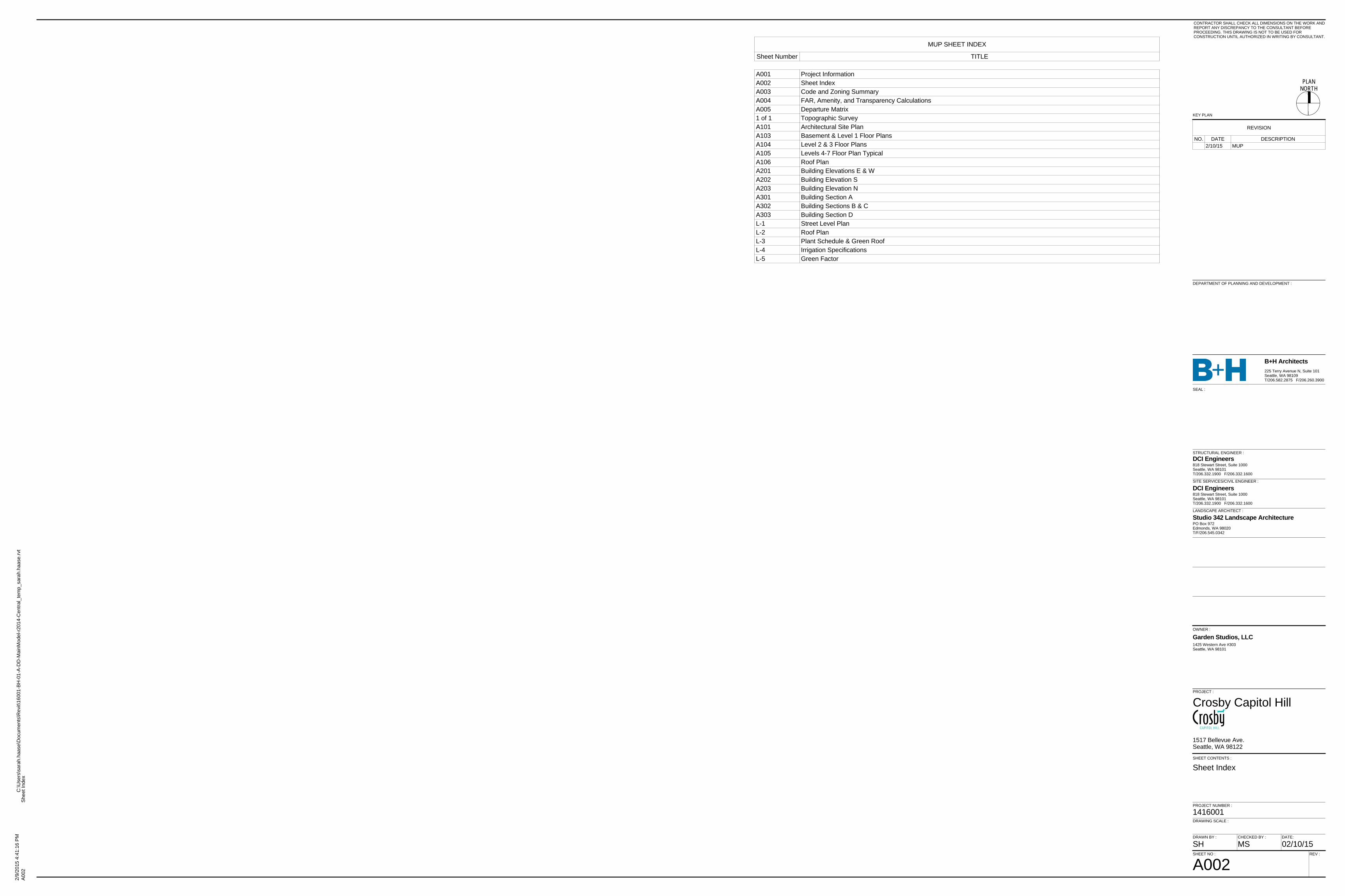
MUP SHEET INDEX
Sheet Number TITLE
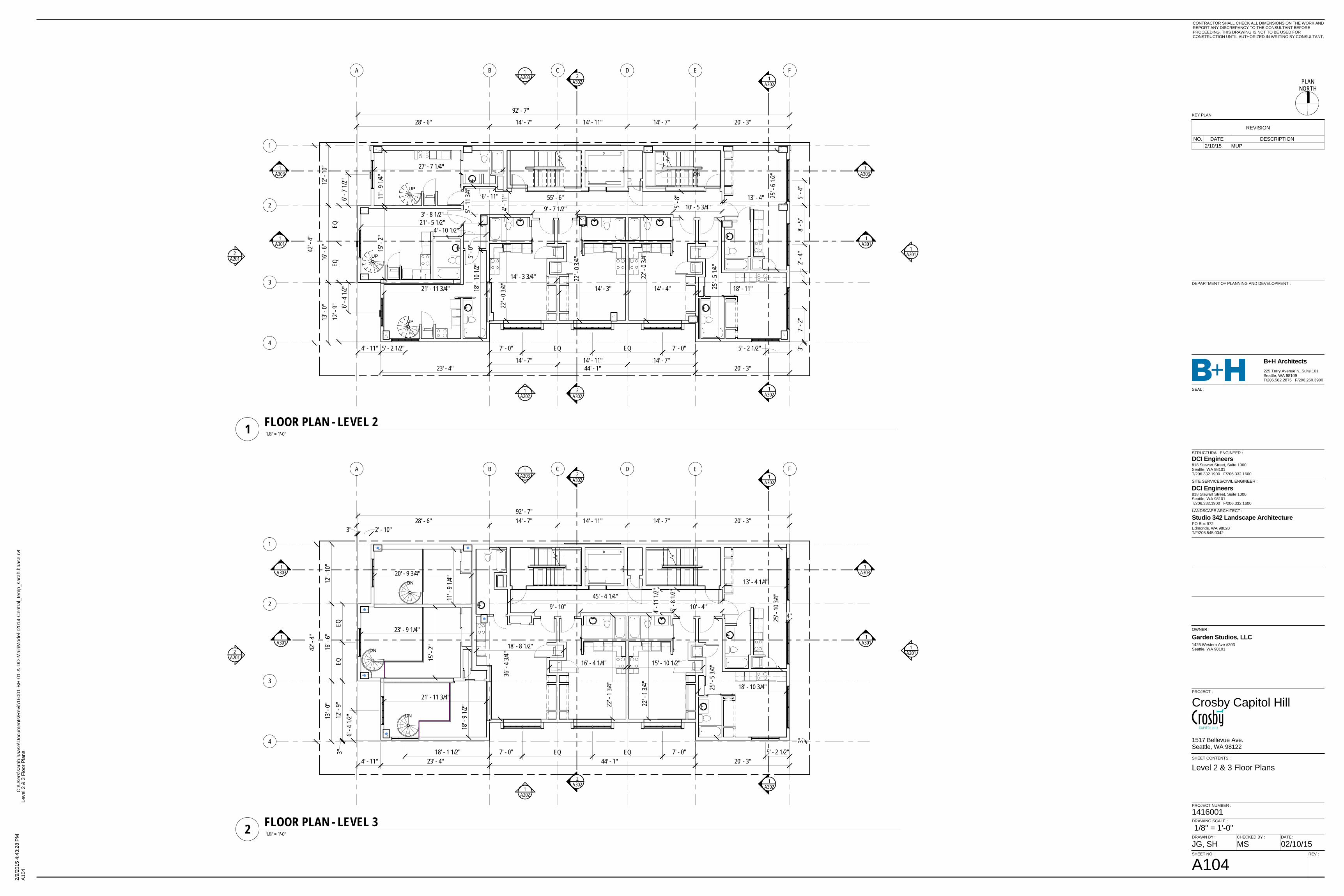
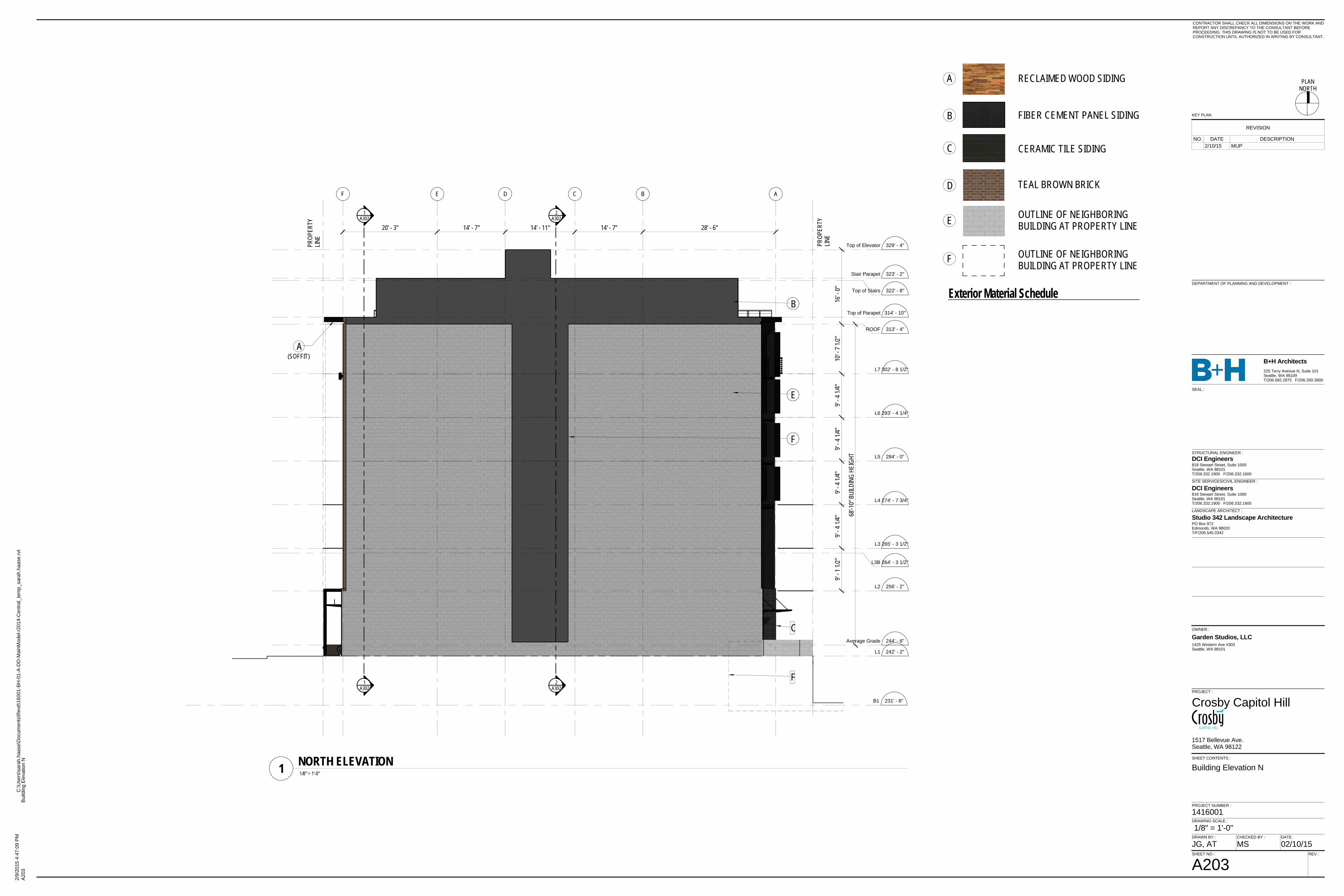
A001 Project InformationA002 Sheet IndexA003 Code and Zoning SummaryA004 FAR, Amenity, and Transparency CalculationsA005 Departure Matrix1 of 1 Topographic SurveyA101 Architectural Site PlanA103 Basement & Level 1 Floor PlansA104 Level 2 & 3 Floor PlansA105 Levels 4-7 Floor Plan TypicalA106 Roof PlanA201 Building Elevations E & WA202 Building Elevation SA203 Building Elevation NA301 Building Section AA302 Building Sections B & CA303 Building Section DL-1 Street Level PlanL-2 Roof PlanL-3 Plant Schedule & Green RoofL-4 Irrigation SpecificationsL-5 Green Factor
REVISION
NO. DATE DESCRIPTION2/10/15 MUP
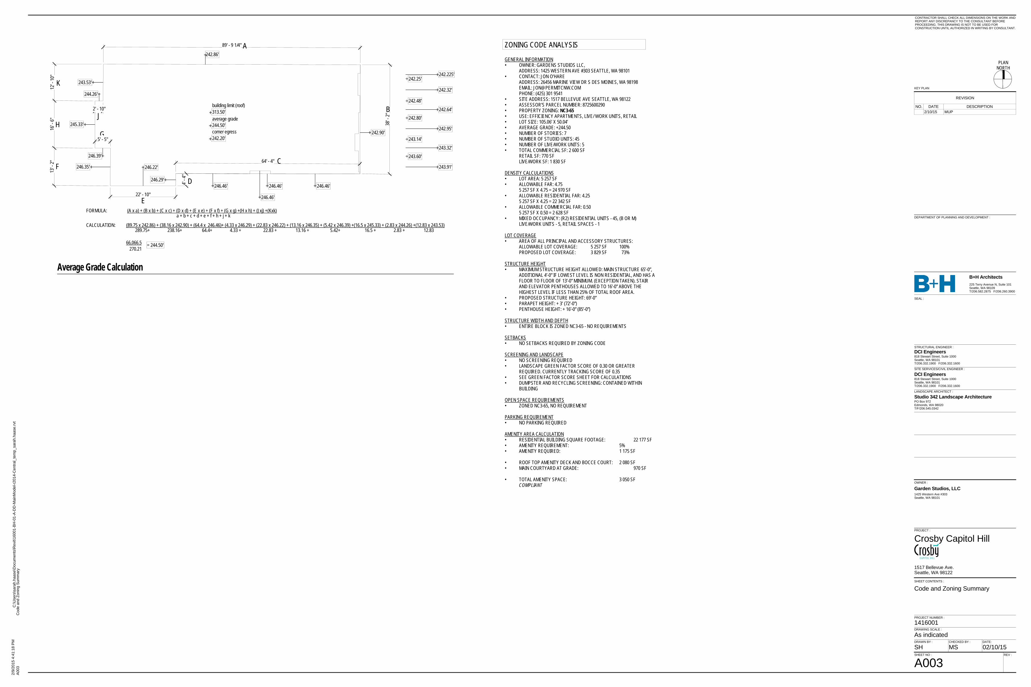
ZONING CODE ANALYSIS
GENERAL INFORMATION• OWNER: GARDENS STUDIOS LLC,
ADDRESS: 1425 WESTERN AVE #303 SEATTLE, WA 98101• CONTACT: JON O’HARE
ADDRESS: 26456 MARINE VIEW DR S DES MOINES, WA 98198EMAIL: [email protected]: (425) 301 9541
• SITE ADDRESS: 1517 BELLEVUE AVE SEATTLE, WA 98122• ASSESSOR’S PARCEL NUMBER: 8725600290• PROPERTY ZONING: NC3-65• USE: EFFICIENCY APARTMENTS, LIVE/ WORK UNITS, RETAIL• LOT SIZE: 105.06’ X 50.04’• AVERAGE GRADE: +244.50• NUMBER OF STORIES: 7• NUMBER OF STUDIO UNITS: 45• NUMBER OF LIVE/WORK UNITS: 5• TOTAL COMMERCIAL SF: 2 600 SF
RETAIL SF: 770 SFLIVE/WORK SF: 1 830 SF
DENSITY CALCULATIONS• LOT AREA: 5 257 SF• ALLOWABLE FAR: 4.75
5 257 SF X 4.75 = 24 970 SF• ALLOWABLE RESIDENTIAL FAR: 4.25
5 257 SF X 4.25 = 22 342 SF• ALLOWABLE COMMERCIAL FAR: 0.50
5 257 SF X 0.50 = 2 628 SF• MIXED OCCUPANCY: (R2) RESIDENTIAL UNITS - 45, (B OR M)
LIVE/WORK UNITS - 5, RETAIL SPACES - 1
LOT COVERAGE• AREA OF ALL PRINCIPAL AND ACCESSORY STRUCTURES:
ALLOWABLE LOT COVERAGE: 5 257 SF 100%PROPOSED LOT COVERAGE: 3 829 SF 73%
STRUCTURE HEIGHT• MAXIMUM STRUCTURE HEIGHT ALLOWED: MAIN STRUCTURE 65’-0”,
ADDITIONAL 4’-0” IF LOWEST LEVEL IS NON RESIDENTIAL, AND HAS AFLOOR TO FLOOR OF 13’-0” MINIMUM. (EXCEPTION TAKEN). STAIRAND ELEVATOR PENTHOUSES ALLOWED TO 16’-0” ABOVE THEHIGHEST LEVEL IF LESS THAN 25% OF TOTAL ROOF AREA.
• PROPOSED STRUCTURE HEIGHT: 69’-0”• PARAPET HEIGHT: + 3’ (72’-0”)• PENTHOUSE HEIGHT: + 16’-0” (85’-0”)
STRUCTURE WIDTH AND DEPTH• ENTIRE BLOCK IS ZONED NC3-65 - NO REQUIREMENTS
SETBACKS• NO SETBACKS REQUIRED BY ZONING CODE
SCREENING AND LANDSCAPE• NO SCREENING REQUIRED• LANDSCAPE GREEN FACTOR SCORE OF 0.30 OR GREATER
REQUIRED. CURRENTLY TRACKING SCORE OF 0.35• SEE GREEN FACTOR SCORE SHEET FOR CALCULATIONS• DUMPSTER AND RECYCLING SCREENING: CONTAINED WITHIN
BUILDING
OPEN SPACE REQUIREMENTS• ZONED NC3-65, NO REQUIREMENT
PARKING REQUIREMENT• NO PARKING REQUIRED
AMENITY AREA CALCULATION• RESIDENTIAL BUILDING SQUARE FOOTAGE: 22 177 SF• AMENITY REQUIREMENT: 5%• AMENITY REQUIRED: 1 175 SF
• ROOF TOP AMENITY DECK AND BOCCE COURT: 2 080 SF• MAIN COURTYARD AT GRADE: 970 SF
• TOTAL AMENITY SPACE: 3 050 SFCOMPLIANT
66,066.5 = 244.50' 270.21
FORMULA: (A x a) + (B x b) + (C x c) + (D x d) + (E x e) + (F x f) + (G x g) +(H x h) + (Jxj) +(Kxk) a + b + c + d + e + f + h + j + k
CALCULATION: (89.75 x 242.86) + (38.16 x 242.90) + (64.4 x 246.46)+ (4.33 x 246.29) + (22.83 x 246.22) + (13.16 x 246.35) + (5.42 x 246.39) +(16.5 x 245.33) + (2.83 x 244.26) +(12.83 x 243.53) 289.75+ 238.16+ 64.4+ 4.33 + 22.83 + 13.16 + 5.42+ 16.5 + 2.83 + 12.83
242.20'corner egress244.50'average grade313.50'building limit (roof)
242.86'
242.225'
242.32'
242.64'
242.95'
243.32'
243.91'
243.60'
242.25'
242.48'
242.80'
243.14'
246.46'
246.46'
246.46'
246.22'246.35'
246.39'
245.33'
244.26'
243.53'
242.90'
246.46'246.29'
A
B
C
D
E
F
GH
J
K
89' - 9 1/4"
38' -
2 "
64' - 4"
4' - 4
"
22' - 10"
13' -
2 "16
' - 6 "
12' -
1 0"
5' - 5"
2' - 10"
Average Grade Calculation
PLANNORTH
KEY PLAN
CONTRACTOR SHALL CHECK ALL DIMENSIONS ON THE WORK ANDREPORT ANY DISCREPANCY TO THE CONSULTANT BEFOREPROCEEDING. THIS DRAWING IS NOT TO BE USED FORCONSTRUCTION UNTIL AUTHORIZED IN WRITING BY CONSULTANT.
STRUCTURAL ENGINEER :
LANDSCAPE ARCHITECT :
SITE SERVICES/CIVIL ENGINEER :
B+H Architects
OWNER :
PROJECT :
SHEET NO :
SHEET CONTENTS :
DRAWING SCALE :
PROJECT NUMBER :
1425 Western Ave #303Seattle, WA 98101
DCI Engineers818 Stewart Street, Suite 1000Seattle, WA 98101T/206.332.1900 F/206.332.1600
Studio 342 Landscape ArchitecturePO Box 972Edmonds, WA 98020T/F/206.545.0342
SEAL :
DRAWN BY : CHECKED BY : DATE:
REV :
225 Terry Avenue N, Suite 101Seattle, WA 98109T/206.582.2875 F/206.260.3900
DCI Engineers818 Stewart Street, Suite 1000Seattle, WA 98101T/206.332.1900 F/206.332.1600
DEPARTMENT OF PLANNING AND DEVELOPMENT :
2/9/
2015
4:4
1:18
PM
C:\U
sers
\sar
ah.h
aase
\Doc
umen
ts\R
evit\
1600
1-BH
-01-
A-D
D-M
ainM
odel
-r201
4-C
entra
l_te
mp_
sara
h.ha
ase.
rvt
As indicated
A003
Cod
e an
d Zo
ning
Sum
mar
y
Crosby Capitol Hill
A003
Code and Zoning Summary
1416001
1517 Bellevue Ave.Seattle, WA 98122
Garden Studios, LLC
SH MS 02/10/15
REVISION
NO. DATE DESCRIPTION2/10/15 MUP
R
R
R
R
R
R
R
R
R
R
R
R
R
R
R
R
R
R
R
R
P P P P P P P P P P P P P P
A
DDDDDD
D
D
D
D
D
D
D
D D
DD
D
D
D
D
D
D
D
D
D
D
D
D
D
D
DD D
D
D D D
D
D
D
D
D
D
D
A
DDDDDD
D
D
D
D
D
D
D
D D
DD
D
D
D
D
D
D
D
D
D
D
D
D
D
D
DD D
D
D D D
D
D
D
D
D
D
D
1820.00 SFUU 70'-0" x 26'-0"
40.00 SFMM 4'-0" x 10'-0"
51.67 SFNN 5'-2" x 10'
16.00 SFOO 4' x 4'
90.31 SFPP 5'-7.75"x 16'-0"
4.00 SFQQ 2'-0" x 2'-0"
24.00 SFRR 4'-0" x 6'-0"
20.00 SFSS 2'-0" x 10'-0"
16.00 SFTT 4'-0" x 4'-0"
33.62 SFBB 2'-9" x 11'-10.625"
111.05 SFDD 2'-8" x 41'-7.70"
17.25 SFAA 3'-7.125" x 4'-9.5"
91.82 SFCC 3'-7.125" x 25'-6.60"
62.70 SFEE 4'-10" x 12'-9"
10.84 SFFF 3'-7.125" x 3'-0.25"
440.45 SFGG 93'-10.60" x 4'-8.30"
128.64 SFHH 32'-10.46" x 3'-11"
21.09 SFII 3'-0" x 7'-0.5"
13.27 SFJJ 2'-5.55" x 5'-4.67"
39.54 SFKK 4'-0" x 9'-10.5"
13.25 SFF 5'-10.75" x 2'-3"
46.44 SFE 7'-11" X 5'-10.4375"
178.22 SFC 8'-9" x 20'-4.5"
56.48 SFB 9'-9.3125" X 5'-9.3125"
501.81 SFA 53'-2.69" x 9'-5.125"
60.14 SFD 8'-9.825" x 6'-9.8125"
1152.24 SFG 89'-9" x 12'-10"
1527.78 SFH 92'-7" x 16'-6"
774.72 SFJ 87'-8" x 8'-10"
91.29 SFI 23'-4" x 3'-11"
79.32 SFK 20'-3" x 3'-11"
1851.02 SFL 68'-3.75" x 27'-1.375"
719.17 SFM 65'-0.125" x 11'-0.75"
79.32 SFN 3'-11" x 20'-3"
1152.24 SFO 89'-9: x 12'-10"
1528.12 SFP 92'-7" x 16'-6.125"
774.39 SFR 87'-8" x 8'-10"
91.40 SFQ 23'-4" x 3'-11"
79.32 SFS 20'-3" x 3'-11"
1152.58 SFT 89'-9: x 12'-10"
1527.77 SFU 92'-7" x 16'-6"
774.44 SFZ 87'-8" x 8'-10"
91.39 SFY 23'-4" x 3'-11"
79.31 SFZA 20'-3" x 3'-11"
4.79 SFX 0'-8" x 7'-3"
4.83 SFW 0'-8" x 7'-3"
4.79 SFV 0'-8" x 7'-3"
529.59 SFZB 77'-7.125" x 9'-9.25"
326.07 SFAA 25'-11.0625" x 12'-6.9375"
488.82 SFBB 28'-9" x 17'-0"
303.86 SFCC 23'-10" x 12'-9"
116.44 SFDD 3'-0.375" x 38'-5"
361.08 SFEE 12'-5.5" x 28'-11.875"
226.96 SFFF 9'-9.3125" x 23'-2.5675"
5.54 SFGG 2'-0.1875" x 2'-9"
267.83 SFII 30'-7.825" x 8'-8.825"
9.32 SFQQ 2'-5.5" x 3'-9.5"
0.40 SFPP 0'-.5" x 0'-9.625"
251.29 SFHH 12'-4" x 20'4.5"
119.62 SFJJ 8'-9.825" x 13'-6.75"
78.47 SFNN 6'-9.5" x 11'6.625"
10.38 SFOO 1'-8" x 5'-6.625"
19.03 SFMM 8'-8" x 2'-2.375"
5.44 SFLL 2'-7.875" x 2'-0.675"
9.46 SFKK 3'-1.875" x 3'-0"
2' -
0"
12' -
0"
38 '- 6" LENGTH OF BUILDING FACADE
1' - 2" BLANK 22' - 11" RETAIL STOREFRONT 14' - 5" BLANK
EXTENT OF BUILDING BEYOND
PLANNORTH
KEY PLAN
CONTRACTOR SHALL CHECK ALL DIMENSIONS ON THE WORK ANDREPORT ANY DISCREPANCY TO THE CONSULTANT BEFOREPROCEEDING. THIS DRAWING IS NOT TO BE USED FORCONSTRUCTION UNTIL AUTHORIZED IN WRITING BY CONSULTANT.
STRUCTURAL ENGINEER :
LANDSCAPE ARCHITECT :
SITE SERVICES/CIVIL ENGINEER :
B+H Architects
OWNER :
PROJECT :
SHEET NO :
SHEET CONTENTS :
DRAWING SCALE :
PROJECT NUMBER :
1425 Western Ave #303Seattle, WA 98101
DCI Engineers818 Stewart Street, Suite 1000Seattle, WA 98101T/206.332.1900 F/206.332.1600
Studio 342 Landscape ArchitecturePO Box 972Edmonds, WA 98020T/F/206.545.0342
SEAL :
DRAWN BY : CHECKED BY : DATE:
REV :
225 Terry Avenue N, Suite 101Seattle, WA 98109T/206.582.2875 F/206.260.3900
DCI Engineers818 Stewart Street, Suite 1000Seattle, WA 98101T/206.332.1900 F/206.332.1600
DEPARTMENT OF PLANNING AND DEVELOPMENT :
2/9/
2015
4:4
3:00
PM
C:\U
sers
\sar
ah.h
aase
\Doc
umen
ts\R
evit\
1600
1-BH
-01-
A-D
D-M
ainM
odel
-r201
4-C
entra
l_te
mp_
sara
h.ha
ase.
rvt
As indicated
A004
FAR
, Am
enity
, and
Tra
nspa
renc
y C
alcu
latio
ns Crosby Capitol Hill
A004
FAR, Amenity, and TransparencyCalculations
1416001
1517 Bellevue Ave.Seattle, WA 98122
Garden Studios, LLC
AT MS 02/10/15
RESIDENTIAL BUILDING SQUARE FOOTAGE = 22 177.10 SFAMENITY REQUIREMENT 5% x 22 177.10 SF = 1 175.39 SFAMENITY PROVIDED = 3 052.24 SF
Area Schedule FAR ResidentialName Area
U 92'-7" x 16'-6" 1527.77 SFV 0'-8" x 7'-3" 4.79 SFW 0'-8" x 7'-3" 4.83 SFX 0'-8" x 7'-3" 4.79 SFY 23'-4" x 3'-11" 91.39 SFZ 87'-8" x 8'-10" 774.44 SFZA 20'-3" x 3'-11" 79.31 SFZB 77'-7.125" x 9'-9.25" 529.59 SFGrand total 22177.10 SF
Area Schedule FAR ResidentialName Area
A 53'-2.69" x 9'-5.125" 501.81 SFB 9'-9.3125" X 5'-9.3125" 56.48 SFC 8'-9" x 20'-4.5" 178.22 SFD 8'-9.825" x 6'-9.8125" 60.14 SFE 7'-11" X 5'-10.4375" 46.44 SFF 5'-10.75" x 2'-3" 13.25 SFG 89'-9" x 12'-10" 1152.24 SFH 92'-7" x 16'-6" 1527.78 SFI 23'-4" x 3'-11" 91.29 SFJ 87'-8" x 8'-10" 774.72 SFK 20'-3" x 3'-11" 79.32 SFL 68'-3.75" x 27'-1.375" 1851.02 SFM 65'-0.125" x 11'-0.75" 719.17 SFN 3'-11" x 20'-3" 79.32 SFO 89'-9: x 12'-10" 1152.24 SFOO 89'-9: x 12'-10" 1152.24 SFOOO 89'-9: x 12'-10" 1152.24 SFP 92'-7" x 16'-6.125" 1528.12 SFPP 92'-7" x 16'-6.125" 1528.12 SFPPP 92'-7" x 16'-6.125" 1528.12 SFQ 23'-4" x 3'-11" 91.40 SFQQ 23'-4" x 3'-11" 91.40 SFQQQ 23'-4" x 3'-11" 91.40 SFR 87'-8" x 8'-10" 774.39 SFRR 87'-8" x 8'-10" 774.39 SFRRR 87'-8" x 8'-10" 774.39 SFS 20'-3" x 3'-11" 79.32 SFSS 20'-3" x 3'-11" 79.32 SFSSS 20'-3" x 3'-11" 79.32 SFT 89'-9: x 12'-10" 1152.58 SF
Amenity Area Schedule
Name Area
MM 4'-0" x 10'-0" 40.00 SFNN 5'-2" x 10' 51.67 SFOO 4' x 4' 16.00 SFPP 5'-7.75"x 16'-0" 90.31 SFQQ 2'-0" x 2'-0" 4.00 SFRR 4'-0" x 6'-0" 24.00 SFSS 2'-0" x 10'-0" 20.00 SFTT 4'-0" x 4'-0" 16.00 SFUU 70'-0" x 26'-0" 1820.00 SFGrand total 3052.24 SF
Amenity Area Schedule
Name Area
AA 3'-7.125" x 4'-9.5" 17.25 SFBB 2'-9" x 11'-10.625" 33.62 SFCC 3'-7.125" x 25'-6.60" 91.82 SFDD 2'-8" x 41'-7.70" 111.05 SFEE 4'-10" x 12'-9" 62.70 SFFF 3'-7.125" x 3'-0.25" 10.84 SFGG 93'-10.60" x 4'-8.30" 440.45 SFHH 32'-10.46" x 3'-11" 128.64 SFII 3'-0" x 7'-0.5" 21.09 SFJJ 2'-5.55" x 5'-4.67" 13.27 SFKK 4'-0" x 9'-10.5" 39.54 SF
Area Schedule FAR CommercialName Area
AA 25'-11.0625" x 12'-6.9375" 326.07 SFBB 28'-9" x 17'-0" 488.82 SFCC 23'-10" x 12'-9" 303.86 SFDD 3'-0.375" x 38'-5" 116.44 SFEE 12'-5.5" x 28'-11.875" 361.08 SFFF 9'-9.3125" x 23'-2.5675" 226.96 SFGG 2'-0.1875" x 2'-9" 5.54 SFHH 12'-4" x 20'4.5" 251.29 SFII 30'-7.825" x 8'-8.825" 267.83 SFJJ 8'-9.825" x 13'-6.75" 119.62 SFKK 3'-1.875" x 3'-0" 9.46 SFLL 2'-7.875" x 2'-0.675" 5.44 SFMM 8'-8" x 2'-2.375" 19.03 SFNN 6'-9.5" x 11'6.625" 78.47 SFOO 1'-8" x 5'-6.625" 10.38 SFPP 0'-.5" x 0'-9.625" 0.40 SFQQ 2'-5.5" x 3'-9.5" 9.32 SFGrand total 2600.01 SFFAR CALCULATION 1/16" = 1'-0"
ALLOWED RESIDENTIAL FAR 4.25 x 5 257 SF = 22 342 SF
ALLOWED COMMERCIAL FAR 0.5 x 5 257 SF = 2 628 SF
RESIDENTIAL FAR = 22 177 SF COMPLIANT
COMMERCIAL FAR = 2 600 SF COMPLIANT
LEVEL 4, 5 & 6 FAR PLANS
LEVEL 7 FAR PLAN
LEVEL 1 COMMERCIAL FAR PLAN
LEVEL 1 RESIDENTIAL FAR PLAN
LEVEL 2 FAR PLAN
LEVEL 3 FAR PLAN
ROOF FAR PLAN AMENITY AREA CALCULATION
1/16" = 1'-0"
ROOF AMENITY AREA PLAN
LEVEL 1 AMENITY AREA PLAN
FACADE TRANSPARENCY CALCULATION
1/16" = 1'-0"1/16" = 1'-0"
1/16" = 1'-0"
1/16" = 1'-0"1/16" = 1'-0"
1/16" = 1'-0"
1/16" = 1'-0"
TRANSPARENCY CALCULATION @ PROPERTY LINE - SMC.23.47A.008.B.2
60% TRANSPARENCY REQUIRED BETWEEN 2' AND 12' ABOVE SIDEWALK
FACADE LENGTH = 38'-6"
BLANK FACADE = 201 SF
TRANSPARENT FACADE = 184 SF
PERCENT TRANSPARENT = 48% SEEKING DEPARTURE
EAST ELEVATION 1/8" = 1'-0"
1/16" = 1'-0"
REVISION
NO. DATE DESCRIPTION2/10/15 MUP

PLANNORTH
KEY PLAN
CONTRACTOR SHALL CHECK ALL DIMENSIONS ON THE WORK ANDREPORT ANY DISCREPANCY TO THE CONSULTANT BEFOREPROCEEDING. THIS DRAWING IS NOT TO BE USED FORCONSTRUCTION UNTIL AUTHORIZED IN WRITING BY CONSULTANT.
STRUCTURAL ENGINEER :
LANDSCAPE ARCHITECT :
SITE SERVICES/CIVIL ENGINEER :
B+H Architects
OWNER :
PROJECT :
SHEET NO :
SHEET CONTENTS :
DRAWING SCALE :
PROJECT NUMBER :
1425 Western Ave #303Seattle, WA 98101
DCI Engineers818 Stewart Street, Suite 1000Seattle, WA 98101T/206.332.1900 F/206.332.1600
Studio 342 Landscape ArchitecturePO Box 972Edmonds, WA 98020T/F/206.545.0342
SEAL :
DRAWN BY : CHECKED BY : DATE:
REV :
225 Terry Avenue N, Suite 101Seattle, WA 98109T/206.582.2875 F/206.260.3900
DCI Engineers818 Stewart Street, Suite 1000Seattle, WA 98101T/206.332.1900 F/206.332.1600
DEPARTMENT OF PLANNING AND DEVELOPMENT :
2/9/
2015
4:4
3:01
PM
C:\U
sers
\sar
ah.h
aase
\Doc
umen
ts\R
evit\
1600
1-BH
-01-
A-D
D-M
ainM
odel
-r201
4-C
entra
l_te
mp_
sara
h.ha
ase.
rvt
A005
Dep
artu
re M
atrix
Crosby Capitol Hill
A005
Departure Matrix
1416001
1517 Bellevue Ave.Seattle, WA 98122
Garden Studios, LLC
SH MS 02/10/15
DEPARTURE MATRIX
STANDARD REQUIREMENT REQUEST AND JUSTIFICATION
DEPARTURE #1
SMC 23.47A.008.B.2TRANSPARENCY
Sixty percent of the street-facingfacade between 2 feet and 8 feetabove the sidewalk shall betransparent.
Due to limited amount of street frontage (50 feet) and requirements for twoexits from the residential portions of the building (14 feet minimumcombined width), this leaves 72% maximum for glazed retail frontage. Thetrash route from the building also requires an additional 6 feet of blankfrontage which reduces the available glazed frontage to 60%. We proposeto include a display window in front of the trash access, to extend theappearance and increase the frontage from 52% to 63%. Subtracting forstorefront mullions, retail space venting louvers, structural members, andawning attachments, the current design has a facade transparency of 48%.
SMC 23.73.014.A.3 The transparency requirements aremet for the portion of the street-facingfacades between 2 feet and 12 feetabove the sidewalk.
REVISION
NO. DATE DESCRIPTION2/10/15 MUP

S1°
41'45"W
50.04'
S88°20'56"E 105.06'
S1°
41'39"W
50.04'
S88°20'48"E 105.06'20'DWY
2 "G- 4" IN
SERT ED
8"PS(R)
8"W(P)
8"W(P)
S1°
41'45"W
412.25'
UP
C
1
2
3
4
A B D E
F 12
LOT 12\NC3P-65
LOT 4NC3P-65
LOT 10NC3P-65
LOT 3NC3P-65
LOT 5NC3P-65
BELL
EVUE
AVE
66,066.5 = 244.50' 270.21
FORMULA: (A x a) + (B x b) + (C x c) + (D x d) + (E x e) + (F x f) + (G x g) +(H x h) + (Jxj) +(Kxk) a + b + c + d + e + f + h + j + k
CALCULATION: (89.75 x 242.86) + (38.16 x 242.90) + (64.4 x 246.46)+ (4.33 x 246.29) + (22.83 x 246.22) + (13.16 x 246.35) + (5.42 x 246.39) +(16.5 x 245.33) + (2.83 x 244.26) +(12.83 x 243.53) 289.75+ 238.16+ 64.4+ 4.33 + 22.83 + 13.16 + 5.42+ 16.5 + 2.83 + 12.83
242.20'corner egress244.50'average grade313.50'building limit (roof)
242.86'
242.225'
242.32'
242.64'
242.95'
243.32'
243.91'
243.60'
242.25'
242.48'
242.80'
243.14'
246.46'
246.46'
246.46'
246.22'246.35'
246.39'
245.33'
244.26'
243.53'
242.90'
246.46'246.29'
A
B
C
D
E
F
GH
J
K
89' - 9 1/4"
38' -
2 "
64' - 4"
4' - 4
"
22' - 10"
13' -
2 "16
' - 6 "
12' -
1 0"
5' - 5"
2' - 10"
Average Grade Calculation
PLANNORTH
KEY PLAN
CONTRACTOR SHALL CHECK ALL DIMENSIONS ON THE WORK ANDREPORT ANY DISCREPANCY TO THE CONSULTANT BEFOREPROCEEDING. THIS DRAWING IS NOT TO BE USED FORCONSTRUCTION UNTIL AUTHORIZED IN WRITING BY CONSULTANT.
STRUCTURAL ENGINEER :
LANDSCAPE ARCHITECT :
SITE SERVICES/CIVIL ENGINEER :
B+H Architects
OWNER :
PROJECT :
SHEET NO :
SHEET CONTENTS :
DRAWING SCALE :
PROJECT NUMBER :
1425 Western Ave #303Seattle, WA 98101
DCI Engineers818 Stewart Street, Suite 1000Seattle, WA 98101T/206.332.1900 F/206.332.1600
Studio 342 Landscape ArchitecturePO Box 972Edmonds, WA 98020T/F/206.545.0342
SEAL :
DRAWN BY : CHECKED BY : DATE:
REV :
225 Terry Avenue N, Suite 101Seattle, WA 98109T/206.582.2875 F/206.260.3900
DCI Engineers818 Stewart Street, Suite 1000Seattle, WA 98101T/206.332.1900 F/206.332.1600
DEPARTMENT OF PLANNING AND DEVELOPMENT :
2/9/
2015
4:4
3:20
PM
C:\U
sers
\sar
ah.h
aase
\Doc
umen
ts\R
evit\
1600
1-BH
-01-
A-D
D-M
ainM
odel
-r201
4-C
entra
l_te
mp_
sara
h.ha
ase.
rvt
As indicated
A101
Arc
hite
ctur
al S
ite P
lan
Crosby Capitol Hill
A101
Architectural Site Plan
1416001
1517 Bellevue Ave.Seattle, WA 98122
Garden Studios, LLC
AT MS 02/10/15 1/8" = 1'-0"1 SITE PLAN
REVISION
NO. DATE DESCRIPTION2/10/15 MUP

UP
UPUP
2A302
2A302
1A301
1A301
1A302
1A302
1A303
1A303
C
1
2
3
4
A B D E F
42' -
6"
12' -
10"
16' -
6"13
' - 0"
96' - 6 1/2"28' - 6" 14' - 7" 14' - 11" 14' - 7" 20' - 3"
39' - 9"
19' -
4 3/4"
20' -
8 1/2"
43' - 4"
14' - 7 3/4" 14' - 3 1/2"
12' -
2"
12' -
2 1/4"
4' - 0" 16' - 2 3/4"
11' -
9"4'
- 6"
17' -
1"
47' - 6"19' -
1 3/4"
5' - 0
" 13' - 4 3/4" 23' -
0 1/4"
20' - 2" 7' - 9"1' - 5 1/4"
10' - 0 3/4"
27' -
11"
7' - 7 1/2"
15' - 10 1/2"
3' - 3 1/2"5' - 7
1/2"
3' - 10 1/2"
5' - 0"
7' - 6
3/4"
6' - 6
3/4"
1A202
1A201
1A203
2A201
2A302
2A302
1A301
1A301
1A302
1A302
1A303
1A303
C
1
2
3
4
A B D E F
25' - 8" 14' - 7" 14' - 11" 14' - 7" 20' - 3"
12' -
10"
16' -
6"13
' - 0"
3"
3' - 7 1/2" 31' - 2 1/2"1' - 7 1/2"
5' - 3"3"23' - 10"
1' - 10 1/2"
4' - 11"
3' - 0
"8'
- 0"
4' - 8
1/2"
3"
42' -
4"
4' - 7
"23
' - 8 3
/4"3'
- 0"
92' - 10"
2' - 10"
7' - 1
"
5 3/4"
27' - 3 1/2"
11' -
6 1/4"
15' -
7 3/4"
25' - 8 3/4"
21' -
9 1/4"
22' - 4"
27' -
11 3/
4"
13' - 3 1/2" 12' - 9 1/2"
27' -
10 1/
4"
7' - 3 1/2"
7' - 9
1/2"
11' -
10 3/
4"
21' -
0"
30' - 2 1/4" 7' - 9"
6' - 6
"
5' - 0"
6' - 0 1/4"
27' -
10 1/
4"
30' - 0 1/2"
12' - 4 3/4" 6' - 11 1/4" 9' - 6 1/4"
8' - 1
"12
' - 6 1
/2"
PLANNORTH
KEY PLAN
CONTRACTOR SHALL CHECK ALL DIMENSIONS ON THE WORK ANDREPORT ANY DISCREPANCY TO THE CONSULTANT BEFOREPROCEEDING. THIS DRAWING IS NOT TO BE USED FORCONSTRUCTION UNTIL AUTHORIZED IN WRITING BY CONSULTANT.
STRUCTURAL ENGINEER :
LANDSCAPE ARCHITECT :
SITE SERVICES/CIVIL ENGINEER :
B+H Architects
OWNER :
PROJECT :
SHEET NO :
SHEET CONTENTS :
DRAWING SCALE :
PROJECT NUMBER :
1425 Western Ave #303Seattle, WA 98101
DCI Engineers818 Stewart Street, Suite 1000Seattle, WA 98101T/206.332.1900 F/206.332.1600
Studio 342 Landscape ArchitecturePO Box 972Edmonds, WA 98020T/F/206.545.0342
SEAL :
DRAWN BY : CHECKED BY : DATE:
REV :
225 Terry Avenue N, Suite 101Seattle, WA 98109T/206.582.2875 F/206.260.3900
DCI Engineers818 Stewart Street, Suite 1000Seattle, WA 98101T/206.332.1900 F/206.332.1600
DEPARTMENT OF PLANNING AND DEVELOPMENT :
2/9/
2015
4:4
3:24
PM
C:\U
sers
\sar
ah.h
aase
\Doc
umen
ts\R
evit\
1600
1-BH
-01-
A-D
D-M
ainM
odel
-r201
4-C
entra
l_te
mp_
sara
h.ha
ase.
rvt
1/8" = 1'-0"
A103
Base
men
t & L
evel
1 F
loor
Pla
ns
Crosby Capitol Hill
A103
Basement & Level 1 Floor Plans
1416001
1517 Bellevue Ave.Seattle, WA 98122
Garden Studios, LLC
JG, SH MS 02/10/15
1/8" = 1'-0"1 FLOOR PLAN - LEVEL B1
1/8" = 1'-0"2 FLOOR PLAN - LEVEL 1
REVISION
NO. DATE DESCRIPTION2/10/15 MUP
UP
UP
UP
DN
DN
DN
DN
1A202
1A201
1A203
2A201
2A302
2A302
1A301
1A301
1A302
1A302
1A303
1A303
C
1
2
3
4
A B D E F
6' - 7
1/2"
16' -
6"EQ
EQ12
' - 9"
4' - 11" 5' - 2 1/2"
23' - 4"
7' - 0" 7' - 0"EQ EQ
44' - 1" 20' - 3"
5' - 2 1/2"
92' - 7"
13' -
0"12
' - 10
"
28' - 6" 14' - 7" 14' - 11" 14' - 7" 20' - 3"
27' - 7 1/4"
11' -
9 1/4"
15' -
2"
21' - 5 1/2"
18' -
10 1/
2"
21' - 11 3/4"
14' - 3 3/4"
22' -
0 3/4" 14' - 3"
22' -
0 3/4"
22' -
0 3/4"
18' - 11"25' -
5 1/4"
13' - 4" 25' -
6 1/2"
55' - 6"
5' - 1
1 3/4"
3' - 8 1/2"
5' - 0
"
4' - 10 1/2"
4' - 1
1"6' - 11"
9' - 7 1/2"
14' - 4"
5' - 4
"8'
- 5"
7' - 2
"
6' - 4
1/2"
42' -
4"
14' - 7" 14' - 11" 14' - 7"
2' - 4
"3"
5' - 8
"
10' - 5 3/4"
1A202
1A201
1A203
2A201
2A302
2A302
1A301
1A301
1A302
1A302
1A303
1A303
C
1
2
3
4
A B D E F
16' -
6"12
' - 9"
44' - 1" 20' - 3"
92' - 7"
2' - 10"
EQEQ
6' - 4
1/2"
7' - 0" 7' - 0"EQ EQ 5' - 2 1/2"
28' - 6" 14' - 7" 14' - 11" 14' - 7" 20' - 3"
12' -
10"
13' -
0"
4"
23' - 4"18' - 1 1/2"3"
3"
42' -
4"
4' - 11"
21' - 11 3/4"
18' -
9 1/2"
23' - 9 1/4"
15' -
2"
20' - 9 3/4"
11' -
9 1/4"
36' -
4 3/4"
18' - 8 1/2"
16' - 4 1/4"
22' -
1 3/4"
22' -
1 3/4"
15' - 10 1/2"
25' -
5 3/4"
18' - 10 3/4"
25' -
10 3/
4"
13' - 4 1/4"
45' - 4 1/4"9' - 10"
4' - 1
1 1/2"
5' - 8
1/2"
10' - 4"
3"
PLANNORTH
KEY PLAN
CONTRACTOR SHALL CHECK ALL DIMENSIONS ON THE WORK ANDREPORT ANY DISCREPANCY TO THE CONSULTANT BEFOREPROCEEDING. THIS DRAWING IS NOT TO BE USED FORCONSTRUCTION UNTIL AUTHORIZED IN WRITING BY CONSULTANT.
STRUCTURAL ENGINEER :
LANDSCAPE ARCHITECT :
SITE SERVICES/CIVIL ENGINEER :
B+H Architects
OWNER :
PROJECT :
SHEET NO :
SHEET CONTENTS :
DRAWING SCALE :
PROJECT NUMBER :
1425 Western Ave #303Seattle, WA 98101
DCI Engineers818 Stewart Street, Suite 1000Seattle, WA 98101T/206.332.1900 F/206.332.1600
Studio 342 Landscape ArchitecturePO Box 972Edmonds, WA 98020T/F/206.545.0342
SEAL :
DRAWN BY : CHECKED BY : DATE:
REV :
225 Terry Avenue N, Suite 101Seattle, WA 98109T/206.582.2875 F/206.260.3900
DCI Engineers818 Stewart Street, Suite 1000Seattle, WA 98101T/206.332.1900 F/206.332.1600
DEPARTMENT OF PLANNING AND DEVELOPMENT :
2/9/
2015
4:4
3:28
PM
C:\U
sers
\sar
ah.h
aase
\Doc
umen
ts\R
evit\
1600
1-BH
-01-
A-D
D-M
ainM
odel
-r201
4-C
entra
l_te
mp_
sara
h.ha
ase.
rvt
1/8" = 1'-0"
A104
Leve
l 2 &
3 F
loor
Pla
ns
Crosby Capitol Hill
A104
Level 2 & 3 Floor Plans
1416001
1517 Bellevue Ave.Seattle, WA 98122
Garden Studios, LLC
JG, SH MS 02/10/15
1/8" = 1'-0"1 FLOOR PLAN - LEVEL 2
1/8" = 1'-0"2 FLOOR PLAN - LEVEL 3
REVISION
NO. DATE DESCRIPTION2/10/15 MUP

UP
1A202
1A201
1A203
2A201
2A302
2A302
1A301
1A301
1A302
1A302
1A303
1A303
16' -
6"12
' - 9"
5' - 2 1/2"23' - 4"
C
C
1 1
2 2
3 3
4 4
A
A
B
B
D
D
E
E F
F
7' - 0"
44' - 1"
EQ EQ 7' - 0" 5' - 2 1/2"
20' - 3"4' - 11"
2' - 10"92' - 7"
6' - 0
1/4"
6' - 8
3/4"
EQEQ
89' - 9"
28' - 4 3/4"
12' -
1 1/4"
21' - 5 1/4"15
' - 2"
20' -
7"21' - 11 3/4" 22
' - 1 3
/4"
16' - 1 3/4"
22' -
1 3/4"
16' - 1 1/4"
22' -
1 3/4"
15' - 10 1/2"
25' -
5 3/4"
18' - 10 3/4"
25' -
10 3/
4"
13' - 4 1/4"55' - 6 1/4"
5' - 0
1/2"
5' - 9
1/2"
9' - 10" 10' - 4"
6' - 11"
11' -
6 1/4"
5' - 0"
3"5'
- 7"
2' - 4
1/4"
5' - 8
3/4"
5' - 3
3/4"
92' - 7"
PLANNORTH
KEY PLAN
CONTRACTOR SHALL CHECK ALL DIMENSIONS ON THE WORK ANDREPORT ANY DISCREPANCY TO THE CONSULTANT BEFOREPROCEEDING. THIS DRAWING IS NOT TO BE USED FORCONSTRUCTION UNTIL AUTHORIZED IN WRITING BY CONSULTANT.
STRUCTURAL ENGINEER :
LANDSCAPE ARCHITECT :
SITE SERVICES/CIVIL ENGINEER :
B+H Architects
OWNER :
PROJECT :
SHEET NO :
SHEET CONTENTS :
DRAWING SCALE :
PROJECT NUMBER :
1425 Western Ave #303Seattle, WA 98101
DCI Engineers818 Stewart Street, Suite 1000Seattle, WA 98101T/206.332.1900 F/206.332.1600
Studio 342 Landscape ArchitecturePO Box 972Edmonds, WA 98020T/F/206.545.0342
SEAL :
DRAWN BY : CHECKED BY : DATE:
REV :
225 Terry Avenue N, Suite 101Seattle, WA 98109T/206.582.2875 F/206.260.3900
DCI Engineers818 Stewart Street, Suite 1000Seattle, WA 98101T/206.332.1900 F/206.332.1600
DEPARTMENT OF PLANNING AND DEVELOPMENT :
2/9/
2015
4:4
3:30
PM
C:\U
sers
\sar
ah.h
aase
\Doc
umen
ts\R
evit\
1600
1-BH
-01-
A-D
D-M
ainM
odel
-r201
4-C
entra
l_te
mp_
sara
h.ha
ase.
rvt
1/8" = 1'-0"
A105
Leve
ls 4
-7 F
loor
Pla
n Ty
pica
l
Crosby Capitol Hill
A105
Levels 4-7 Floor Plan Typical
1416001
1517 Bellevue Ave.Seattle, WA 98122
Garden Studios, LLC
JG, SH MS 02/10/15
1/8" = 1'-0"1 FLOOR PLAN - LEVELS 4-7 TYPICAL
REVISION
NO. DATE DESCRIPTION2/10/15 MUP

R
R
R
R
R
R
R
R
R
R
R
R
R
R
R
R
R
R
R
R
P P P P P P P P P P P P P P
UP
1A202
1A201
1A203
2A201
2A302
2A302
1A301
1A301
1A302
1A302
1A303
1A303
C
1
2
3
4
A B D E F
28' - 6" 14' - 7" 14' - 11" 14' - 7" 20' - 3"98' - 1"
12' -
10"
16' -
6"13
' - 0"
1' - 3" 3' - 1"
1' - 3" 5' - 2" 6" 4' - 0"23' - 4" 43' - 1" 6" 20' - 3" 3"
42' -
7"
3"
5' - 0"
22' - 8 1/4"
77' - 7 1/4" 7' - 2" 4' - 0"
9' - 9
1/4"
7' - 1
1 1/2"
23' - 4 3/4" 16' - 9" 9' - 9 3/4" 27' - 8"
12
BOCCE COURT
SOLAR PANELS
PLANNORTH
KEY PLAN
CONTRACTOR SHALL CHECK ALL DIMENSIONS ON THE WORK ANDREPORT ANY DISCREPANCY TO THE CONSULTANT BEFOREPROCEEDING. THIS DRAWING IS NOT TO BE USED FORCONSTRUCTION UNTIL AUTHORIZED IN WRITING BY CONSULTANT.
STRUCTURAL ENGINEER :
LANDSCAPE ARCHITECT :
SITE SERVICES/CIVIL ENGINEER :
B+H Architects
OWNER :
PROJECT :
SHEET NO :
SHEET CONTENTS :
DRAWING SCALE :
PROJECT NUMBER :
1425 Western Ave #303Seattle, WA 98101
DCI Engineers818 Stewart Street, Suite 1000Seattle, WA 98101T/206.332.1900 F/206.332.1600
Studio 342 Landscape ArchitecturePO Box 972Edmonds, WA 98020T/F/206.545.0342
SEAL :
DRAWN BY : CHECKED BY : DATE:
REV :
225 Terry Avenue N, Suite 101Seattle, WA 98109T/206.582.2875 F/206.260.3900
DCI Engineers818 Stewart Street, Suite 1000Seattle, WA 98101T/206.332.1900 F/206.332.1600
DEPARTMENT OF PLANNING AND DEVELOPMENT :
2/9/
2015
5:0
6:26
PM
C:\U
sers
\sar
ah.h
aase
\Doc
umen
ts\R
evit\
1600
1-BH
-01-
A-D
D-M
ainM
odel
-r201
4-C
entra
l_te
mp_
sara
h.ha
ase.
rvt
1/8" = 1'-0"
A106
Roo
f Pla
n
Crosby Capitol Hill
A106
Roof Plan
1416001
1517 Bellevue Ave.Seattle, WA 98122
Garden Studios, LLC
AT MS 02/10/15
1/8" = 1'-0"1 FLOOR PLAN - ROOF
REVISION
NO. DATE DESCRIPTION2/10/15 MUP

L1 242' - 2"
L2 256' - 2"
L3 265' - 3 1/2"
L4 274' - 7 3/4"
L5 284' - 0"
L6 293' - 4 1/4"
L7 302' - 8 1/2"
ROOF 313' - 4"
L3B 264' - 3 1/2"
1A301
1A301
Top of Parapet 314' - 10"
Top of Stairs 322' - 8"
Top of Elevator 329' - 4"
Stair Parapet 323' - 2"
1A303
1A303 1234
13' - 0" 16' - 6" 12' - 10"
9' - 1
1/2"
9' - 4
1/4"
9' - 4
1/4"
9' - 4
1/4"
9' - 4
1/4"
10' -
7 1/2"
16' -
0"
Average Grade 244' - 6"
PROP
ERTY
LINE
PROP
ERTY
LINE
GAS METER LOCATION
FIRE DEPARTMENT CONNECTIONRESIDENTIAL ENTRY COMMERCIAL STOREFRONT _
68'-1
0" B
UILD
ING
HEIG
HT
EMERGENCY EGRESSAND UTILITY
L1 242' - 2"
L2 256' - 2"
L3 265' - 3 1/2"
L4 274' - 7 3/4"
L5 284' - 0"
L6 293' - 4 1/4"
L7 302' - 8 1/2"
ROOF 313' - 4"
L3B 264' - 3 1/2"
1A301
1A301
Top of Parapet 314' - 10"
Top of Stairs 322' - 8"
Top of Elevator 329' - 4"
Stair Parapet 323' - 2"
1A303
1A3031 2 3 4
12' - 10" 16' - 6" 13' - 0"
9' - 1
1/2"
9' - 4
1/4"
9' - 4
1/4"
9' - 4
1/4"
9' - 4
1/4"
10' -
7 1/2"
16' -
0"
Average Grade 244' - 6"
14' -
0"
PROP
ERTY
LINE
PROP
ERTY
LINE
68'-1
0" B
UILD
ING
HEIG
HT
FIBER CEMENT PANEL SIDING
CERAMIC TILE SIDING
TEAL BROWN BRICK
OUTLINE OF NEIGHBORINGBUILDING AT PROPERTY LINE
RECLAIMED WOOD SIDINGA
B
C
D
E
Exterior Material Schedule
F
OUTLINE OF NEIGHBORINGBUILDING AT PROPERTY LINE
PLANNORTH
KEY PLAN
CONTRACTOR SHALL CHECK ALL DIMENSIONS ON THE WORK ANDREPORT ANY DISCREPANCY TO THE CONSULTANT BEFOREPROCEEDING. THIS DRAWING IS NOT TO BE USED FORCONSTRUCTION UNTIL AUTHORIZED IN WRITING BY CONSULTANT.
STRUCTURAL ENGINEER :
LANDSCAPE ARCHITECT :
SITE SERVICES/CIVIL ENGINEER :
B+H Architects
OWNER :
PROJECT :
SHEET NO :
SHEET CONTENTS :
DRAWING SCALE :
PROJECT NUMBER :
1425 Western Ave #303Seattle, WA 98101
DCI Engineers818 Stewart Street, Suite 1000Seattle, WA 98101T/206.332.1900 F/206.332.1600
Studio 342 Landscape ArchitecturePO Box 972Edmonds, WA 98020T/F/206.545.0342
SEAL :
DRAWN BY : CHECKED BY : DATE:
REV :
225 Terry Avenue N, Suite 101Seattle, WA 98109T/206.582.2875 F/206.260.3900
DCI Engineers818 Stewart Street, Suite 1000Seattle, WA 98101T/206.332.1900 F/206.332.1600
DEPARTMENT OF PLANNING AND DEVELOPMENT :
2/9/
2015
4:4
4:48
PM
C:\U
sers
\sar
ah.h
aase
\Doc
umen
ts\R
evit\
1600
1-BH
-01-
A-D
D-M
ainM
odel
-r201
4-C
entra
l_te
mp_
sara
h.ha
ase.
rvt
1/8" = 1'-0"
A201
Bui
ldin
g El
evat
ions
E &
W
Crosby Capitol Hill
A201
Building Elevations E & W
1416001
1517 Bellevue Ave.Seattle, WA 98122
Garden Studios, LLC
JG, AT MS 02/10/15 1/8" = 1'-0"1 EAST ELEVATION 1/8" = 1'-0"2 WEST ELEVATION
C
B
D
C
B
D
B
REVISION
NO. DATE DESCRIPTION2/10/15 MUP
A A(SOFFIT) (SOFFIT)

L1 242' - 2"
L2 256' - 2"
L3 265' - 3 1/2"
L4 274' - 7 3/4"
L5 284' - 0"
L6 293' - 4 1/4"
L7 302' - 8 1/2"
ROOF 313' - 4"
L3B 264' - 3 1/2"
2A302
2A302
1A302
1A302
Top of Parapet 314' - 10"
Top of Stairs 322' - 8"
Top of Elevator 329' - 4"
Stair Parapet 323' - 2"
CA B D E F
20' - 3"14' - 7"14' - 11"14' - 7"28' - 6"
16' -
0"10
' - 7 1
/2"9'
- 4 1/
4"9'
- 4 1/
4"9'
- 4 1/
4"9'
- 4 1/
4"9'
- 1 1/
2"
Average Grade 244' - 6"
11' -
8"
2' - 4
"
7' - 11"
PROP
ERTY
LINE
PROP
ERTY
LINE
BUILD
ING
HEIG
HT 6
8'-10
"
FIBER CEMENT PANEL SIDING
CERAMIC TILE SIDING
TEAL BROWN BRICK
OUTLINE OF NEIGHBORINGBUILDING AT PROPERTY LINE
RECLAIMED WOOD SIDINGA
B
C
D
E
Exterior Material Schedule
F
OUTLINE OF NEIGHBORINGBUILDING AT PROPERTY LINE
PLANNORTH
KEY PLAN
CONTRACTOR SHALL CHECK ALL DIMENSIONS ON THE WORK ANDREPORT ANY DISCREPANCY TO THE CONSULTANT BEFOREPROCEEDING. THIS DRAWING IS NOT TO BE USED FORCONSTRUCTION UNTIL AUTHORIZED IN WRITING BY CONSULTANT.
STRUCTURAL ENGINEER :
LANDSCAPE ARCHITECT :
SITE SERVICES/CIVIL ENGINEER :
B+H Architects
OWNER :
PROJECT :
SHEET NO :
SHEET CONTENTS :
DRAWING SCALE :
PROJECT NUMBER :
1425 Western Ave #303Seattle, WA 98101
DCI Engineers818 Stewart Street, Suite 1000Seattle, WA 98101T/206.332.1900 F/206.332.1600
Studio 342 Landscape ArchitecturePO Box 972Edmonds, WA 98020T/F/206.545.0342
SEAL :
DRAWN BY : CHECKED BY : DATE:
REV :
225 Terry Avenue N, Suite 101Seattle, WA 98109T/206.582.2875 F/206.260.3900
DCI Engineers818 Stewart Street, Suite 1000Seattle, WA 98101T/206.332.1900 F/206.332.1600
DEPARTMENT OF PLANNING AND DEVELOPMENT :
2/9/
2015
4:4
5:52
PM
C:\U
sers
\sar
ah.h
aase
\Doc
umen
ts\R
evit\
1600
1-BH
-01-
A-D
D-M
ainM
odel
-r201
4-C
entra
l_te
mp_
sara
h.ha
ase.
rvt
1/8" = 1'-0"
A202
Bui
ldin
g El
evat
ion
S
Crosby Capitol Hill
A202
Building Elevation S
1416001
1517 Bellevue Ave.Seattle, WA 98122
Garden Studios, LLC
JG, AT MS 02/10/15
1/8" = 1'-0"1 SOUTH ELEVATION
C
B
D
A
F
A(SOFFIT)
A(SOFFIT)
REVISION
NO. DATE DESCRIPTION2/10/15 MUP
L1 242' - 2"
L2 256' - 2"
L3 265' - 3 1/2"
L4 274' - 7 3/4"
L5 284' - 0"
L6 293' - 4 1/4"
L7 302' - 8 1/2"
ROOF 313' - 4"
B1 231' - 8"
L3B 264' - 3 1/2"
2A302
2A302
1A302
1A302
Top of Parapet 314' - 10"
Top of Stairs 322' - 8"
Top of Elevator 329' - 4"
Stair Parapet 323' - 2"
C ABDEF
28' - 6"14' - 7"14' - 11"14' - 7"20' - 3"
9' - 1
1/2"
9' - 4
1/4"
9' - 4
1/4"
9' - 4
1/4"
9' - 4
1/4"
10' -
7 1/2"
16' -
0"
Average Grade 244' - 6"
PROP
ERTY
LINE
PROP
ERTY
LINE
68'-1
0" B
UILD
ING
HEIG
HT
B
E
C
F
F
FIBER CEMENT PANEL SIDING
CERAMIC TILE SIDING
TEAL BROWN BRICK
OUTLINE OF NEIGHBORINGBUILDING AT PROPERTY LINE
RECLAIMED WOOD SIDINGA
B
C
D
E
Exterior Material Schedule
F
OUTLINE OF NEIGHBORINGBUILDING AT PROPERTY LINE
PLANNORTH
KEY PLAN
CONTRACTOR SHALL CHECK ALL DIMENSIONS ON THE WORK ANDREPORT ANY DISCREPANCY TO THE CONSULTANT BEFOREPROCEEDING. THIS DRAWING IS NOT TO BE USED FORCONSTRUCTION UNTIL AUTHORIZED IN WRITING BY CONSULTANT.
STRUCTURAL ENGINEER :
LANDSCAPE ARCHITECT :
SITE SERVICES/CIVIL ENGINEER :
B+H Architects
OWNER :
PROJECT :
SHEET NO :
SHEET CONTENTS :
DRAWING SCALE :
PROJECT NUMBER :
1425 Western Ave #303Seattle, WA 98101
DCI Engineers818 Stewart Street, Suite 1000Seattle, WA 98101T/206.332.1900 F/206.332.1600
Studio 342 Landscape ArchitecturePO Box 972Edmonds, WA 98020T/F/206.545.0342
SEAL :
DRAWN BY : CHECKED BY : DATE:
REV :
225 Terry Avenue N, Suite 101Seattle, WA 98109T/206.582.2875 F/206.260.3900
DCI Engineers818 Stewart Street, Suite 1000Seattle, WA 98101T/206.332.1900 F/206.332.1600
DEPARTMENT OF PLANNING AND DEVELOPMENT :
2/9/
2015
4:4
7:09
PM
C:\U
sers
\sar
ah.h
aase
\Doc
umen
ts\R
evit\
1600
1-BH
-01-
A-D
D-M
ainM
odel
-r201
4-C
entra
l_te
mp_
sara
h.ha
ase.
rvt
1/8" = 1'-0"
A203
Bui
ldin
g El
evat
ion
N
Crosby Capitol Hill
A203
Building Elevation N
1416001
1517 Bellevue Ave.Seattle, WA 98122
Garden Studios, LLC
JG, AT MS 02/10/15
1/8" = 1'-0"1 NORTH ELEVATION
A
REVISION
NO. DATE DESCRIPTION2/10/15 MUP
(SOFFIT)
L1 242' - 2"
L2 256' - 2"
L3 265' - 3 1/2"
L4 274' - 7 3/4"
L5 284' - 0"
L6 293' - 4 1/4"
L7 302' - 8 1/2"
ROOF 313' - 4"
B1 231' - 8"
L3B 264' - 3 1/2"
Top of Parapet 314' - 10"
Top of Stairs 322' - 8"
Top of Elevator 329' - 4"
Stair Parapet 323' - 2"
16' -
0"
CA B D E F
9' - 4
1/4"
9' - 4
1/4"
9' - 1
1/2"
9' - 4
1/4"
9' - 4
1/4"
14' -
0"10
' - 7 1
/2"
CORR
RESIDENTIALUNIT
RESIDENTIALUNITCORR
LIVE/WORK UNIT LIVE/WORK UNIT LIVE/WORK UNIT RESLOBBY
RETAIL
STORAGE CORR TRASH CORRIDOR
CORR
CORR
CORR
CORR
CORR
CORR
CORR
CORR
CORR
RESIDENTIALUNIT
RESIDENTIALUNIT
RESIDENTIALLOFT UNIT
RESIDENTIALUNIT
RESIDENTIALUNIT
RESIDENTIALUNIT
RESIDENTIALUNIT
RESIDENTIALUNIT
RESIDENTIALUNIT
RESIDENTIALUNIT
RESIDENTIALUNIT
RESIDENTIALUNIT
RESIDENTIALUNIT
RESIDENTIALUNIT
RESIDENTIALUNIT
RESIDENTIALUNIT
RESIDENTIALUNIT
RESIDENTIALUNIT
RESIDENTIALUNIT
RESIDENTIALUNIT
RESIDENTIALUNIT
RESIDENTIALUNIT
RESIDENTIALUNIT
RESIDENTIALUNIT
RESIDENTIALUNIT
RESIDENTIALUNIT
RESIDENTIALUNIT
Average Grade 244' - 6"
20' - 3"14' - 7"14' - 11"14' - 7"28' - 6"
92' - 10"
PROP
ERTY
LINE
PROP
ERTY
LINE
68'-1
0" B
UILD
ING
HEIG
HT
PLANNORTH
KEY PLAN
CONTRACTOR SHALL CHECK ALL DIMENSIONS ON THE WORK ANDREPORT ANY DISCREPANCY TO THE CONSULTANT BEFOREPROCEEDING. THIS DRAWING IS NOT TO BE USED FORCONSTRUCTION UNTIL AUTHORIZED IN WRITING BY CONSULTANT.
STRUCTURAL ENGINEER :
LANDSCAPE ARCHITECT :
SITE SERVICES/CIVIL ENGINEER :
B+H Architects
OWNER :
PROJECT :
SHEET NO :
SHEET CONTENTS :
DRAWING SCALE :
PROJECT NUMBER :
1425 Western Ave #303Seattle, WA 98101
DCI Engineers818 Stewart Street, Suite 1000Seattle, WA 98101T/206.332.1900 F/206.332.1600
Studio 342 Landscape ArchitecturePO Box 972Edmonds, WA 98020T/F/206.545.0342
SEAL :
DRAWN BY : CHECKED BY : DATE:
REV :
225 Terry Avenue N, Suite 101Seattle, WA 98109T/206.582.2875 F/206.260.3900
DCI Engineers818 Stewart Street, Suite 1000Seattle, WA 98101T/206.332.1900 F/206.332.1600
DEPARTMENT OF PLANNING AND DEVELOPMENT :
2/9/
2015
4:4
7:11
PM
C:\U
sers
\sar
ah.h
aase
\Doc
umen
ts\R
evit\
1600
1-BH
-01-
A-D
D-M
ainM
odel
-r201
4-C
entra
l_te
mp_
sara
h.ha
ase.
rvt
1/8" = 1'-0"
A301
Build
ing
Sect
ion
A
Crosby Capitol Hill
A301
Building Section A
1416001
1517 Bellevue Ave.Seattle, WA 98122
Garden Studios, LLC
AT, SH Checker 02/10/15
1/8" = 1'-0"1 BUILDING SECTION A
REVISION
NO. DATE DESCRIPTION2/10/15 MUP

L1 242' - 2"
L2 256' - 2"
L3 265' - 3 1/2"
L4 274' - 7 3/4"
L5 284' - 0"
L6 293' - 4 1/4"
L7 302' - 8 1/2"
ROOF 313' - 4"
B1 231' - 8"
L3B 264' - 3 1/2"
Top of Parapet 314' - 10"
Top of Stairs 322' - 8"
Top of Elevator 329' - 4"
Stair Parapet 323' - 2"
1234
14' -
0"9'
- 1 1/
2"9'
- 4 1/
4"9'
- 4 1/
4"9'
- 4 1/
4"9'
- 4 1/
4"10
' - 7 1
/2"16
' - 0"
13' - 0" 16' - 6" 12' - 10"
RESIDENTIALUNIT
RESIDENTIALUNIT
RESIDENTIALUNIT
RESIDENTIALUNIT
RESIDENTIALUNIT
RESIDENTIALUNIT
RESIDENTIALUNIT
RESIDENTIALUNIT
RESIDENTIALUNIT
RESIDENTIALUNIT
RETAIL UTILITY
CORRIDORTRANSFORMER
VAULT
Average Grade 244' - 6"
PROP
ERTY
LINE
PROP
ERTY
LINE
68'-1
0" B
UILD
ING
HEIG
HT
10' -
6"
RESIDENTIALUNIT
RESIDENTIALUNIT
EXIS
ITIN
G BU
ILDIN
G
L1 242' - 2"
L2 256' - 2"
L3 265' - 3 1/2"
L4 274' - 7 3/4"
L5 284' - 0"
L6 293' - 4 1/4"
L7 302' - 8 1/2"
ROOF 313' - 4"
B1 231' - 8"
L3B 264' - 3 1/2"
Top of Parapet 314' - 10"
Top of Stairs 322' - 8"
Top of Elevator 329' - 4"
Stair Parapet 323' - 2"
1234
14' -
0"9'
- 1 1/
2"9'
- 4 1/
4"9'
- 4 1/
4"9'
- 4 1/
4"9'
- 4 1/
4"10
' - 7 1
/2"9'
- 10"
6' - 2
"
13' - 0" 16' - 6" 12' - 10"
LIVE/WORKUNIT
CORR
BOILERROOM
STORAGEROOM
CORR
CORR
CORR
CORR
CORR
CORR
CORR
RESIDENTIALUNIT
RESIDENTIALUNIT
RESIDENTIALUNIT
RESIDENTIALUNIT
RESIDENTIALUNIT
RESIDENTIALUNIT
Average Grade 244' - 6"
PROP
ERTY
LINE
PROP
ERTY
LINE
NEW
EXI
SITI
NG B
UILD
ING
"UND
ER C
ONST
RUCT
ION"
10' -
6"
68'-1
0" B
UILD
ING
HEIG
HT
EXIS
ITIN
G BU
ILDIN
G
PLANNORTH
KEY PLAN
CONTRACTOR SHALL CHECK ALL DIMENSIONS ON THE WORK ANDREPORT ANY DISCREPANCY TO THE CONSULTANT BEFOREPROCEEDING. THIS DRAWING IS NOT TO BE USED FORCONSTRUCTION UNTIL AUTHORIZED IN WRITING BY CONSULTANT.
STRUCTURAL ENGINEER :
LANDSCAPE ARCHITECT :
SITE SERVICES/CIVIL ENGINEER :
B+H Architects
OWNER :
PROJECT :
SHEET NO :
SHEET CONTENTS :
DRAWING SCALE :
PROJECT NUMBER :
1425 Western Ave #303Seattle, WA 98101
DCI Engineers818 Stewart Street, Suite 1000Seattle, WA 98101T/206.332.1900 F/206.332.1600
Studio 342 Landscape ArchitecturePO Box 972Edmonds, WA 98020T/F/206.545.0342
SEAL :
DRAWN BY : CHECKED BY : DATE:
REV :
225 Terry Avenue N, Suite 101Seattle, WA 98109T/206.582.2875 F/206.260.3900
DCI Engineers818 Stewart Street, Suite 1000Seattle, WA 98101T/206.332.1900 F/206.332.1600
DEPARTMENT OF PLANNING AND DEVELOPMENT :
2/9/
2015
4:4
7:14
PM
C:\U
sers
\sar
ah.h
aase
\Doc
umen
ts\R
evit\
1600
1-BH
-01-
A-D
D-M
ainM
odel
-r201
4-C
entra
l_te
mp_
sara
h.ha
ase.
rvt
1/8" = 1'-0"
A302
Build
ing
Sect
ions
B &
C
Crosby Capitol Hill
A302
Building Sections B & C
1416001
1517 Bellevue Ave.Seattle, WA 98122
Garden Studios, LLC
AT, SH MS 02/10/15
1/8" = 1'-0"1 BUILDING SECTION B 1/8" = 1'-0"2 BUILDING SECTION C
REVISION
NO. DATE DESCRIPTION2/10/15 MUP

L1 242' - 2"
L2 256' - 2"
L3 265' - 3 1/2"
L4 274' - 7 3/4"
L5 284' - 0"
L6 293' - 4 1/4"
L7 302' - 8 1/2"
ROOF 313' - 4"
B1 231' - 8"
L3B 264' - 3 1/2"
Top of Parapet 314' - 10"
Top of Stairs 322' - 8"
Top of Elevator 329' - 4"
Stair Parapet 323' - 2"
CA B D E F
Average Grade 244' - 6"
68'-1
0" B
UILD
ING
HEIG
HT
16' -
0"10
' - 7 1
/2"9'
- 4 1/
4"9'
- 4 1/
4"9'
- 4 1/
4"9'
- 4 1/
4"9'
- 1 1/
2"14
' - 0"
10' -
6"
28' - 6" 14' - 7" 14' - 11" 14' - 7" 20' - 3"
PROP
ERTY
LINE
PROP
ERTY
LINE
STAIR 2 EXTERIORUTILITY
GYM STAIR 2
RESIDENTIALUNIT
CORR
RESIDENTIALUNIT
RESIDENTIALUNIT
RESIDENTIALUNIT
LIVE/WORKUNIT
RESIDENTIALLOFT UNIT
RESIDENTIALUNIT
RESIDENTIALUNIT
RESIDENTIALUNIT
RESIDENTIALUNIT
RESIDENTIALUNIT
RESIDENTIALUNIT
STAIR2
STAIR1
ELEVMACHROOM
ELEVGENERATORENCLOSURE
STAIR1
TRASH
PLANNORTH
KEY PLAN
CONTRACTOR SHALL CHECK ALL DIMENSIONS ON THE WORK ANDREPORT ANY DISCREPANCY TO THE CONSULTANT BEFOREPROCEEDING. THIS DRAWING IS NOT TO BE USED FORCONSTRUCTION UNTIL AUTHORIZED IN WRITING BY CONSULTANT.
STRUCTURAL ENGINEER :
LANDSCAPE ARCHITECT :
SITE SERVICES/CIVIL ENGINEER :
B+H Architects
OWNER :
PROJECT :
SHEET NO :
SHEET CONTENTS :
DRAWING SCALE :
PROJECT NUMBER :
1425 Western Ave #303Seattle, WA 98101
DCI Engineers818 Stewart Street, Suite 1000Seattle, WA 98101T/206.332.1900 F/206.332.1600
Studio 342 Landscape ArchitecturePO Box 972Edmonds, WA 98020T/F/206.545.0342
SEAL :
DRAWN BY : CHECKED BY : DATE:
REV :
225 Terry Avenue N, Suite 101Seattle, WA 98109T/206.582.2875 F/206.260.3900
DCI Engineers818 Stewart Street, Suite 1000Seattle, WA 98101T/206.332.1900 F/206.332.1600
DEPARTMENT OF PLANNING AND DEVELOPMENT :
2/9/
2015
4:4
7:19
PM
C:\U
sers
\sar
ah.h
aase
\Doc
umen
ts\R
evit\
1600
1-BH
-01-
A-D
D-M
ainM
odel
-r201
4-C
entra
l_te
mp_
sara
h.ha
ase.
rvt
1/8" = 1'-0"
A303
Build
ing
Sect
ion
D
Crosby Capitol Hill
A303
Building Section D
1416001
1517 Bellevue Ave.Seattle, WA 98122
Garden Studios, LLC
AT, SH MS 02/10/15
1/8" = 1'-0"1 BUILDING SECTION D
REVISION
NO. DATE DESCRIPTION2/10/15 MUP


41 4" 1"
12"
2'-0"
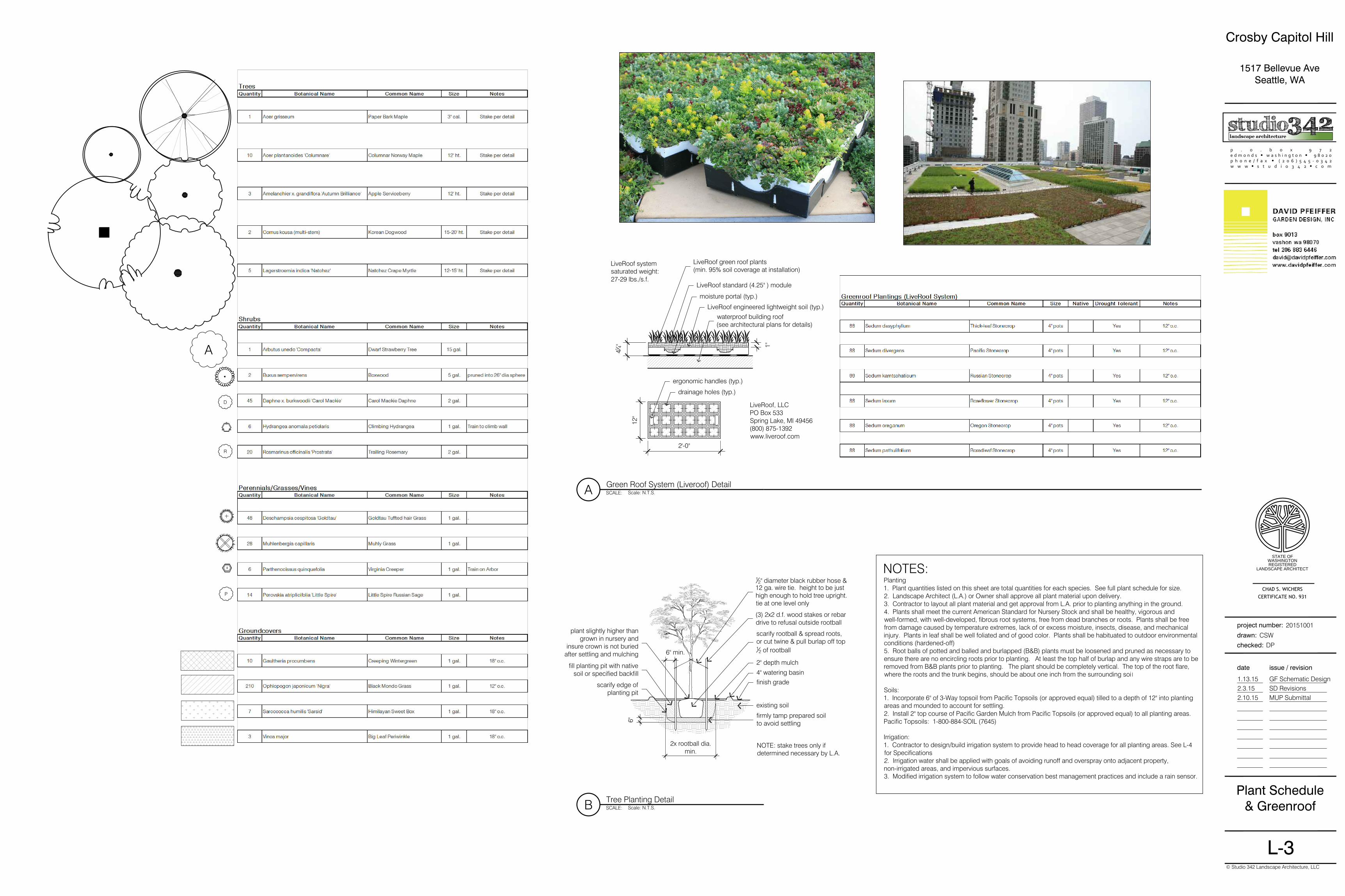
LiveRoof standard (4.25" ) module
moisture portal (typ.)
LiveRoof engineered lightweight soil (typ.)
LiveRoof green roof plants(min. 95% soil coverage at installation)
waterproof building roof(see architectural plans for details)
drainage holes (typ.)
ergonomic handles (typ.)
LiveRoof, LLCPO Box 533Spring Lake, MI 49456(800) 875-1392www.liveroof.com
LiveRoof systemsaturated weight:27-29 lbs./s.f.
NOTES:Planting1. Plant quantities listed on this sheet are total quantities for each species. See full plant schedule for size.2. Landscape Architect (L.A.) or Owner shall approve all plant material upon delivery.3. Contractor to layout all plant material and get approval from L.A. prior to planting anything in the ground.4. Plants shall meet the current American Standard for Nursery Stock and shall be healthy, vigorous andwell-formed, with well-developed, fibrous root systems, free from dead branches or roots. Plants shall be freefrom damage caused by temperature extremes, lack of or excess moisture, insects, disease, and mechanicalinjury. Plants in leaf shall be well foliated and of good color. Plants shall be habituated to outdoor environmentalconditions (hardened-off)5. Root balls of potted and balled and burlapped (B&B) plants must be loosened and pruned as necessary toensure there are no encircling roots prior to planting. At least the top half of burlap and any wire straps are to beremoved from B&B plants prior to planting. The plant should be completely vertical. The top of the root flare,where the roots and the trunk begins, should be about one inch from the surrounding soi l
Soils:1. Incorporate 6" of 3-Way topsoil from Pacific Topsoils (or approved equal) tilled to a depth of 12" into plantingareas and mounded to account for settling.2. Install 2" top course of Pacific Garden Mulch from Pacific Topsoils (or approved equal) to all planting areas.Pacific Topsoils: 1-800-884-SOIL (7645)
Irrigation:1. Contractor to design/build irrigation system to provide head to head coverage for all planting areas. See L-4for Specifications2. Irrigation water shall be applied with goals of avoiding runoff and overspray onto adjacent property,non-irrigated areas, and impervious surfaces.3. Modified irrigation system to follow water conservation best management practices and include a rain sensor.
2x rootball dia.min.
6"
6" min.
existing soil
firmly tamp prepared soilto avoid settling
finish grade4" watering basin
2" depth mulch
scarify rootball & spread roots,or cut twine & pull burlap off top1
2 of rootball
(3) 2x2 d.f. wood stakes or rebardrive to refusal outside rootball
12" diameter black rubber hose &
12 ga. wire tie. height to be justhigh enough to hold tree upright.tie at one level only
plant slightly higher than grown in nursery and
insure crown is not buried after settling and mulching
fill planting pit with native soil or specified backfill
scarify edge ofplanting pit
NOTE: stake trees only ifdetermined necessary by L.A.
P
R
A
D
p . o . b o x 9 7 2e d m o n d s I w a s h i n g t o n I 9 8 0 2 0p h o n e / f a x I ( 2 0 6 ) 5 4 5 - 0 3 4 2w w w I s t u d i o 3 4 2 I c o m
issue / revisiondate
checked:
drawn:
project number:
© Studio 342 Landscape Architecture, LLC
Plant Schedule& Greenroof
CSW
DP
1.13.15 GF Schematic Design2.3.15 SD Revisions2.10.15 MUP Submittal
20151001
Crosby Capitol Hill
1517 Bellevue AveSeattle, WA
L-3
CHAD S. WICHERSCERTIFICATE NO. 931
STATE OF
WASHINGTON
REGISTERED
LANDSCAPE ARCHITECT
SCALE:
Green Roof System (Liveroof) DetailScale: N.T.S.A
SCALE:
Tree Planting DetailScale: N.T.S.B
p . o . b o x 9 7 2e d m o n d s I w a s h i n g t o n I 9 8 0 2 0p h o n e / f a x I ( 2 0 6 ) 5 4 5 - 0 3 4 2w w w I s t u d i o 3 4 2 I c o m
issue / revisiondate
checked:
drawn:
project number:
© Studio 342 Landscape Architecture, LLC
IrrigationSpecifications
CSW
DP
1.13.15 GF Schematic Design2.3.15 SD Revisions2.10.15 MUP Submittal
20151001
Crosby Capitol Hill
1517 Bellevue AveSeattle, WA
L-4
CHAD S. WICHERSCERTIFICATE NO. 931
STATE OF
WASHINGTON
REGISTERED
LANDSCAPE ARCHITECT
1.00 General
1.01 SummaryA. Provide a fully automatic bidder designed irrigation system installedby a qualified, licensed Contractor.
1.02 Quality AssuranceA. Perform work in strict accordance with the applicable plumbing,electrical, and health codes.B. Obtain and pay for all permits and approvals required by the localjurisdictional authorities for the full operation of the system.C. The work is subject to Landscape Architect tests and inspections asspecified. Furnish written notice to the Landscape Architect 72 hoursminimum prior to the required test or inspection.D. Include a master valve on the incoming mainline at the backflowpreventer location. Advise Landscape Architect if mainline pressure isinsufficient to permit the additional pressure loss of a master valve.
1.03 System CoverageA. Provide full coverage* in all planted areas. Exercise professionaljudgement in selection, location, height, and angle of sprinkler heads.Select and locate heads to avoid erosion, spraying building, andexcessively washing walks. Shrub and lawn zones, sprinkler heads withwidely varied precipitation rates, and differing sun exposures are to bevalved separately. (*Full coverage is defined as head to headcoverage with all plants and lawns receiving adequate water).
1.04 GuaranteeA. Guarantee system against defects of installation and material for aperiod of one (1) year after acceptance of sprinkler system. Duringguarantee period check, clear, and adjust sprinkler heads and otherwiseinsure adequate operation of system at maximum three (3) monthintervals during the year.
1.05 SubmittalsA. Plans - Two (2) sets of irrigation plans showing pipe and head layout,spray pattern, and equipment list.B. Catalog Cuts - Manufacturer's descriptions of all proposed materials.C. Make submittals to Landscape Architect for review prior toconstruction. Approval of plans and materials by Landscape Architectdoes not change the Contractor's responsibility for providing fullcoverage in planting areas.
1.06 SubstitutionsA. Substitutions to the equipment specified will be permitted only withthe express written approval of the Landscape Architect and when thesubstituted item is equal or better in quality than the item originallyspecified. The final determination for equal rests with the LandscapeArchitect.
1.07 As-Built DrawingsA. Maintain a current record of all pipes and equipment placement andrecord any variations from the original design.B. Dimension pipe and equipment in variance to plans to twopermanent structures sufficient for location after burial.C. Submit a neat and legible as-built drawing of complete irrigationsystem upon completion of irrigation system and prior to releases offinal payment. Provide reduced scale copy of plan, plastic encased, forattachment inside controller door.
2.00 Materials
2.01 MeterA. Per local code.
2.02 Galvanized Pipe and AccessoriesA. Pipe - Standard weight steel pipe, electrical resistance weld, ASTMSchedule 40.B. Fittings - Malleable galvanized fittings.C. Exterior Coatings - Primer and Matte Black Alkyd Oil Enamel forabove grade pipe and fittings. 'Fields 125' bituminous coating for pipeand fittings below grade.
2.03 Plastic Pipe and FittingsA. Pipe - Mainline: Schedule 40 PVC pipe, manufactured from a Type I,Grade I Polyvinyl Chloride (PVC) compound with a Cell Classification of12454 per ASTM D1784. The pipe shall be manufactured in strictcompliance to ASTM D1785 and D2665 (where applicable).Lateral lines: PVC 1120 or 1220, Class 200 conforming to U.S. ProductStandard PS 22-70 and ASTM 2241, marked with manufacturer's name,class of pipe, NSF seal, and date and shift of manufacturing run.Provide uniform, smooth and glossy pipe with no evidence of interior orexterior extrusion marks. Pipe end pre-belled or straight to receivesolvent-weld couplings.
2.04 Sprinkler Heads and NozzlesA. Rainbird, Toro, Weathermatic, or approved equal. Brass or plastic.Pop-up type spray heads in all shrub beds and small lawn areas. Smallpop-up impact spray heads or gear driven rotary pop-ups in medium
sized lawn areas. Large impact or rotary pop-ups in large lawn areaswhere spray is not likely to drift into windows. Select nozzles to providefull coverage and to prevent erosion and overspray of buildings,windows, walks, etc.... Galvanized risers used only upon approval ofLandscape Architect.
2.05 RisersA. Plastic bodies - 6" & 12" high pop-up Rainbird 1800 Series, orapproved equal.B. Brass bodies - Only if requested by Owner.
2.06 Automatic ValvesA. 24 volt, normally closed, provide with flow adjustment/shut-off handleand manual bleed cock.B. Brass, or plastic. Weathermatic 8200CR or 11000CR, or approvedequal.
2.07 Master ValveA. Brass only.
2.08 Valve BoxesA. General - Black or green plastic with bolt down lock-top capability.B. Automatic Valves/Pressure Reducing Valve - Carson 1320B-13B orapproved equal. Lid marked valve.C. Backflow Preventer - Carson 1730C-12B or approval equal.D. Shut-off Valve - Carson 10" diameter or approved equal.E. Quick Coupling Valve - Carson 6" diameter or approved equal.
2.09 Automatic ControllersA. 120 volt service with 24 volt output and UL approved, lockable door.Size for minimum of two additional future zones. 14 day capability andoption of any 30 minute start of a 24 hour day. Time spread per station0-60 minutes. Include Master Valve terminal or a pump start terminal forMaster Valve operation.
2.10 WireA. UL approved UF and UL marked insulation jackets +/- #14 UFdirect burial , solid copper, from controller to valves. ASTM B-3. Red orblack for hot side, white for common ground, any third color for auxillarywires. Multi-strand wire is acceptable if distance from controller tofurthest valve is less than 500 feet. 3M DBY below grade wire splices.Screw-type and taped splices above grade per code.
2.11 Quick Coupling Valve For Air BlowoutA. Rainbird or approved equal with 1" MPT key.
2.12 Shut-Off ValveA. Champion Angle Valve, Mueller, or approved equal. Stop and Wastevalve where allowed by code. Provide 30" long key for valve operation.
2.13 Backflow PreventerA. Per State of Washington approved list and as approved by localcode. Febco #850 double check valve assembly or approved equal.Include resilient seat gate valve on each end of unit and 12" brass,screwed end, 150# WOG drive valve on downstream side.
2.14 Pressure Reducing ValveA. Watts #223, Wilkens #500, or approved equal. Contractor has theoption of utilizing a pressure reducing valve or automatic valves withpressure reducing capability.
2.15 Check ValvesA. KBI King-Check or approved equal. SAMS (seal-a-matic) may beused with an auto-drain and a gravel sump (minimum 1 CF) at thelowest end of each zone.
3.00 Installation
3.01 ExaminationA. Prior to starting work carefully inspect the prepartory work of othertrades and verify that such work is acceptable for the installation of thiswork. Report all unacceptable conditions to the Landscape Architect.Do not begin work until unacceptable conditions have been resolved.Beginning work constitutes Contractor acceptance of conditions.
3.02 MeterA. Verify need with local water purveyor. Determine location, size, andtype of pipe in the service from the main.
3.03 TrenchingA. Make trenches for irrigation system. Finish trenches free from rock,debris, or sharp articles. Provide depth to acheive minimum 16" coverfor shrub beds, 12" for lawn areas, and 16" cover for mainline.Removed unused trench spoils from site.
3.04 PipeA. Cut PVC pipe ends at 90 degrees to the pipe length and clean allcutting prior to cementing. Wipe pipe ends clean with rag lightly wettedwith PVC thinner. Apply cement with light coat on inside of fitting and
heavier coat on outside of pipe. Insert pipe into fitting and give aquarter turn to seat cement. Wipe excess cement from outside of pipe.
3.05 SleevingA. Class 200 PVC, 4" minimum diameter. Schedule 40 under asphalt orcrushed rock paving. Verify with Landscape Architect if sleeves are tobe installed by others.
3.06 Spray Heads and RisersA. Set shrub heads with flange flush or slightly below finish grade at aminimum distance of 4 inches from planter edge. Provide double swingjoint or flexible swing pipe and spiral barbed fitting (connection atbottom of sprinkler body only) for connection to lateral.B. Install lawn heads flush with finish to clear mowing equipment.Provide three (3) Marlex street ells and one (1) PVC Schedule 80 nipple,or flex pipe connection to lateral (connection at bottom of sprinkler bodyonly).
3.07 NozzlesA. Select nozzles to provide full coverage without causing erosionproblems, staining of siding, or drift onto windows.
3.08 Electric WireA. Install wire in conduit where required by local code. Bury at sufficientdepth to meet local code and in no case less than bottom side ofparallel pipe. Bundle control wires and tape at 10' intervals. Tapebundles to adjacent pipe. Install wire in sleeves under all pavement.Splices shall occur at boxes only.
3.09 System ExpansionA. Provide a minimum of two (2) auxillary wires for future valve locations.Run one unconnected spare control wire from the controller thougheach intermediate valve to terminate at the valve(s) at the ends of themain line. Loop at least 24" of wire at each of the intermediate valveboxes. Mark spare wires at the controllers and in boxes with permananttag. Coil spare wire in plastic valve box.
3.10 Backfilling TrenchesA. Set pipe to ensure no puncture damage or future settlement. Laymainline pipe with manufacturer's designations toward top of trench.Compact backfill to no less than 90% density at optimum moisturecontent. Backfill around sprinkler heads to restrict movement of headsby external force. Repair all trench settlement and finished surfacedamage due to settling during warranty period.
3.11 Automatic ValvesA. Install in specified valve box. Provide PVC nipple (minimum 4" long)on the inlet side and compression coupling or PVC union on the outletside. Adjust flow with stem of valve to balance system. Mount valveboxes flush with finish grade unless otherwise indicated on drawings.Install immediately adjacent to walks or curbs (in shrub beds wherepossible). Provide 6" of pea gravel in bottom of valve box with 6" clearfrom gravel to underside of valve.
3.12 Master ValveA. Size to match mainline size.
3.13 Backflow Prevention UnitA. Install per local applicable code. Verify location with LandscapeArchitect. Otherwise Contractor is responsible for cost of relocation.Install galvanized ground joint unions on both inlet and outlet sides.Install Double Check Assembly in plastic box with minimum of 6" ofgravel at bottom of box. Provide positive and verifiable drainage out ofbox. If required, install Reduced Pressure Backflow Preventer per code.
3.14 Pressure Reducing ValveA. Install in plastic valve box with un-marked lid. Set so system doesnot fog with auto valves wide open.
3.15 Automatic ControllerA. Review exact location with Landscape Architect prior to installation.Connect to 120 volt service. Provide conduit/wire from controllerlocation to valves. Label each station to clearly identify location of eachvalve.
3.16 Quick Couple ValveA. Install in a 10" diameter valve box. Ensure valve can be operatedfrom finish grade.
3.17 Shut Off ValveA. Install in a 10" diameter valve box. If Stop and Waste Valve isallowed by code, provide 1 cubic foot gravel sump beneath valve.
3.18 Check ValvesA. Provide low head check valves on risers of lowest heads to preventleakage.3.19 Riser PaintingA. Paint all galvanized pipe and fittings with one coat minimum ofspecified material. Touch up after assembly.
3.20 System FlushingA. Flush entire system prior to installation of sprinkler heads/nozzles.After capping all risers, remove cap nearest automatic valve, flush, andrecap. Repeat this process until last head on circuit is flushed. If apressure reducing valve is included in system, open wide for maximumpressure during flushing operation.
3.21 Pressure TestA. Leave all system joints, connections, etc... exposed until aftercompletion and acceptance of pressure test. Cap and open entiresystem to full main static pressure (pressure reducing valve wide open)for a period of two (2) hours. If static exceeds 80 psi, set PRV at 80psifor testing laterals. Test mainlines at 100 psi. Visually check jointsand connections for leaks. Repair all leaks, however minor. Contractorhas the option of using AWWA pressure test (test with approvedpressure pump at 100 psi with no more than 5 psi loss in 15 minutes).Deliver written record of test to Landscape Architect.
3.22 Performance TestsA. Upon completion of system installation and after flushing andpressure tests are completed, operate system in presence ofLandscape Architect. Correct all deficiencies until the system isapproved.
3.23 AdjustingA. Substitute or modify up to 5% of total nozzles to accomodatelocations and density of plants and ensure full coverage.
3.24 System FamiliarizationA. Upon completion of system installation, flushing, and pressure tests,and acceptance of system by Landscape Architect, operate the systemin the presence of the Owner. Provide keys and/or other toolsnecessary to operate/drain/activate the system and spend adequatetime with Owner to ensure operation/maintenance/winterization cancontinue after departure of Contractor. Submit written verification ofcompliance to Landscape Architect indicating date and personsinvolved. Contractor is liable for all damage or losses resulting fromfailure to comply with provisions of this paragraph.
3.25 System ProtectionA. Deactivate and drain the system prior to the onset of frezzingseasonand reactivate at the onset of spring season. Accomplish eachat least once during the guarantee period. If installation is completedwhen system is not in use, winterize after testing. Certify by letter thedates of winterization/activation. Repair damage from failure to comply.Purge system with low pressure and low volume compressed air. Donot allow pipe or compressor to get hot to the touch.
3.26 Final ApprovalA. Upon completion of all tests, final approval for system will becontingent upon Contractor providing signed and approvedsprinkler/plumbing/health/electrical permits as may be applicable in thearea, and as-built drawings of the complete system.
END OF SECTION
p . o . b o x 9 7 2e d m o n d s I w a s h i n g t o n I 9 8 0 2 0p h o n e / f a x I ( 2 0 6 ) 5 4 5 - 0 3 4 2w w w I s t u d i o 3 4 2 I c o m
issue / revisiondate
checked:
drawn:
project number:
© Studio 342 Landscape Architecture, LLC
Green Factor
CSW
DP
1.13.15 GF Schematic Design2.3.15 SD Revisions2.10.15 MUP Submittal
20151001
Crosby Capitol Hill
1517 Bellevue AveSeattle, WA
L-5
CHAD S. WICHERSCERTIFICATE NO. 931
STATE OF
WASHINGTON
REGISTERED
LANDSCAPE ARCHITECT
SCALE:
Green Factor Works SheetsScale: N.T.S.