floor standing rsf gas-fired condensing … · abbreviations: Ø diameter ng natural gas ......
TRANSCRIPT

UK/IE
INSTRUCTION MANUALINSTALLATION COMMISSIONING & SERVICING
8 716 115 219c (03.2010)
THE APPLIANCE IS FOR USE WITH
NATURAL GAS OR L.P.G. (Cat II 2H3P TYPE C13, C33 & C93)
NATURAL GAS:
GREENSTAR HIGHFLOW 440CDi GC NUMBER 47-406-24
GREENSTAR HIGHFLOW 550CDi GC NUMBER 47-406-25
LIQUID PETROLEUM GAS:
GREENSTAR HIGHFLOW 440CDi GC NUMBER 47-406-26
GREENSTAR HIGHFLOW 550CDi GC NUMBER 47-406-27
GREENSTARHIGHFLOW 440CDi & 550CDiFOR SEALED CENTRAL HEATING SYSTEMS AND MAINS FED DOMESTIC HOT WATER
FLOOR STANDING RSF GAS-FIRED CONDENSING COMBINATIONBOILER

INSTALLATION & SERVICING INSTRUCTIONSCONTACT INFORMATION
INSTALLATION & SERVICING INSTRUCTIONSCONTACT INFORMATIONINSTALLATION & SERVICING INSTRUCTIONS
8 716 115 219c (03.2010)
PLEASE READ THESE INSTRUCTIONS CAREFULLY BEFORE STARTING INSTALLATION.
THESE INSTRUCTIONS ARE APPLICABLE TO THE PRODUCT MODEL(S) STATED ON
THE FRONT COVER OF THIS MANUAL ONLY AND MUST NOT BE USED WITH ANY
OTHER MAKE OR MODEL OF APPLIANCE.
THE INSTRUCTIONS APPLY IN THE UK/IE ONLY AND MUST BE FOLLOWED EXCEPT
FOR ANY STATUTORY OBLIGATION.
THIS APPLIANCE MUST BE INSTALLED BY A COMPETENT REGISTERED ENGINEER,
SUCH AS A BRITISH GAS OR OTHER GAS SAFE REGISTERED PERSONNEL.
IF YOU ARE IN ANY DOUBT CONTACT THE WORCESTER TECHNICAL SUPPORT
HELPLINE.
DISTANCE LEARNING AND TRAINING COURSES ARE AVAILABLE FROM WORCESTER,
PART OF THE BOSCH GROUP.
PLEASE LEAVE THESE INSTRUCTIONS, THE USER GUIDE AND THE COMPLETED
BENCHMARK LOG BOOK (AT THE BACK OF THIS MANUAL) OR A CERTIFICATE
CONFIRMING COMPLIANCE WITH IS 813 (EIRE ONLY) WITH THE USER OR AT
THE GAS METER AFTER INSTALLATION OR SERVICING.
WORCESTER, BOSCH GROUP:RECEPTION: 0844 892 9900MAIN FAX: 01905 754619TECHNICAL: 0844 892 3366SERVICE: 0844 892 3000SPARES: 01905 752571LITERATURE: 0844 892 9800TRAINING: 01905 752526SALES: 01905 752640WEBSITE: worcester-bosch.co.uk
WATER TREATMENT:FERNOX 01799 550811fernox.com
SENTINEL 0800 389 4670sentinel-solutions.net
FLUE TERMINAL GUARDS:
TOWER FLUE COMPONENTS
VALE RISE, TONBRIDGE, TN9 1TB
TEL: 01732 351680
tfc-group.co.uk
ABBREVIATIONS:
Ø Diameter
NG Natural Gas
LPG Liquid Petroleum Gas
CH Central Heating
DHW Domestic Hot Water
TRV Thermostatic Radiator Valve
IP Ingress Protection
RS Room sealed flue
N/A Not allowed
SEDBUK Seasonal Efficiency for Domestic Boilers in the United Kingdom
Store the appliance in a dry area prior toinstallation.
THIS BOILER IS NOT SUITABLE FOR ROOFSPACE INSTALLATION.
IMPORTANT HANDLING INSTRUCTIONS:It is advised that at least two people areinvolved in the transfer of the packagedappliance from the van to the point ofinstallation.A suitable truck should be used.The boiler is secured to a wooden board withscrews. It is advised that no attempt shouldbe made to move the packaged appliancewithout the use of a suitable truck.Before removing the carton it is advised thatthe top flaps are opened and the ancillaryitems removed and set to one side.The carton can now be lifted off the boiler.Remove the plastic bag protecting the boilersurfaces and place safely away from theworking area.Remove the boiler (complete with board) fromthe pallet before removing the securing screws.The boiler is mounted on small wheels andcan now be slid off the board and guided intothe installation position.Care should be taken not to damage anypanels.Two people are required to move the appliancefrom the board into the installation position.
GENERAL HANDLING GUIDELINES:• Lift only a manageable weight, or ask for help.• When lifting, bend the knees, and keep the
back straight and feet apart.• Do not lift and twist at the same time.• Lift and carry items close to the body• Wear protective clothing and gloves to
protect from any sharp edges
SYMBOLS USED IN THIS MANUAL:
Domestic hot water
Central heating
Room thermostat
Frost thermostat
Wait time period
Programmer/timer OFF
Programmer ON CH only
Programmer ON DHW only
Programmer ON CH and DHW
Cold water main supply
Electricity supply
Fuel supply
COMMERCIAL INSTALLATION:
IF INSTALLING A GROUP OF APPLIANCES TOGETHER, ON COMMERCIAL PREMISES,
THAT TOTALS MORE THAN 70KW, THEN THE APPLIANCES MUST BE INSTALLED IN
ACCORDANCE WITH THE REQUIREMENTS OF IGE/UP/10 THEREFORE A COMMERCIAL
GAS QUALIFICATION WILL BE REQUIRED.

INSTALLATION & SERVICING INSTRUCTIONS CONTENTS
SA
FET
Y &
RE
GU
LATI
ON
SFA
ULT
FIN
DIN
G&
DIA
GR
AM
SA
PP
LIA
NC
EIN
FOR
MA
TIO
NP
RE
-IN
STA
LLA
TIO
NIN
STA
LLA
TIO
NC
OM
MIS
SIO
NIN
GS
ER
VIC
ING
& S
PA
RE
SC
ON
VE
RS
ION
KIT
S
CONTENTS
18 716 115 219c (03.2010)
SAFETY & REGULATIONS
SAFETY PRECAUTIONS 2
INSTALLATION REGULATIONS 2
APPLIANCE INFORMATION
GENERAL INFORMATION 3
TECHNICAL DATA 4
LAYOUT & COMPONENTS 5
PRE-INSTALLATION
CLEANING PRIMARY SYSTEMS 6
MAINS SUPPLIES 7
WATER SYSTEMS & PIPEWORK 9
CONDENSATE PIPEWORK 11
PRESSURE RELIEF PIPEWORK 12
BOILER LOCATION & CLEARANCES 13
MOUNTING FRAME CONNECTIONS 14
TERMINAL OUTLET POSITIONS 17
ROOM SEALED FLUE OPTIONS 18
INSTALLATION
UNPACKING THE BOILER 19
MOUNTING FRAME FIXING / FLUE OPENING 20
MOUNTING FRAME CONNECTIONS 21
FLUE LENGTHS/FLUE MEASURING & CUTTING 22
FLUE MEASURING & CUTTING 23
FLUE INSTALLATION 25
STANDARD FLUE INSTALLATION 26
EXTENDED FLUE INSTALLATION 27
FLUE TERMINAL PLUME MANAGEMENT 28
CONDENSATE, GAS & WATER CONNECTIONS 29
PRESSURE RELIEF VALVE OUTLET 30
ELECTRICAL 31
COMMISSIONING
PRE-COMMISSIONING CHECKS 32
FILLING THE SYSTEM 33
WATER TREATMENT 34
STARTING THE APPLIANCE 35
FINISHING COMMISSIONING 36
SERVICING & SPARES
INSPECTION AND SERVICE 37
REPLACEMENT OF PARTS 41
SETTING THE GAS/AIR RATIO 46
SHORT PARTS LIST 47
CONVERSION KITS
L.P.G. CONVERSION 48
FAULT FINDING & DIAGRAMS
ELECTRICAL WIRING DIAGRAM 49
CENTRAL HEATING FUNCTION 50
DHW FUNCTION 51
FAULT FINDING 52
BENCHMARK LOG BOOK AT REAR OF MANUAL

SAFETY PRECAUTIONS INSTALLATION REGULATIONS
IF YOU SMELL GAS:
DO NOT SMOKE OR STRIKE MATCHES.
DO NOT TURN ELECTRICAL SWITCHES ON OR OFF.
PUT OUT NAKED FLAMES.
OPEN DOORS AND WINDOWS.
KEEP PEOPLE AWAY FROM THE AREA AFFECTED.
TURN OFF THE CONTROL VALVE AT THE METER.
CALL YOUR GAS COMPANY.
-OR-
CALL 0800 111 999 NATIONAL GRID EMERGENCY SERVICES.
BOILER OPERATION:
This boiler must only be operated by a responsible adult who has been instructedin, understands and is aware of the boiler’s operating conditions and effects.
BENCHMARK:
Benchmark places responsibilities on both manufacturers and installers. The purposeis to ensure that customers are provided with the correct equipment for their needs,that it is installed, commissioned and serviced in accordance with the manufacturer’sinstructions by competent persons and that it meets the requirements of the appropriateBuilding Regulations. The Benchmark Checklist can be used to demonstrate compliancewith Building Regulations and should be provided to the customer for future reference.
Installers are required to carry out installation, commissioning and servicing work inaccordance with the Benchmark Code of Practice which is available from the Heatingand Hotwater Industry Council who manage and promote the scheme.Visit www.centralheating.co.uk for more information.
IMPORTANT: The completed Benchmark Log Book will be required in the event of any warranty work and may be required by the local Building Control Inspector.
HEALTH & SAFETY:
The appliance contains no asbestos and no substances have been used in theconstruction process that contravene the COSHH Regulations (Control of SubstancesHazardous to Health Regulations 1988). Where applicable, the CE mark indicatescompliance with relative EU Directives.
COMBUSTIBLE AND CORROSIVE MATERIALS:
Do not store or use any combustible materials (paper, thinners, paints etc.) insideor within the vicinity of the appliance.
The combustion air must be kept clear of chemically aggressive substances, whichcan corrode the appliance and invalidate any warranty.
FITTING & MODIFICATIONS:
Fitting the appliance and any controls to the appliance may only be carried out bya competent engineer in accordance with these instructions and the relevant InstallationRegulations.
Flue systems must not be modified in any way other than as described in the fittinginstructions.
Any misuse or unauthorised modifications to the appliance, flue or associatedcomponents and systems could invalidate the warranty. The manufacturer acceptsno liability arising from any such actions, excluding statutory rights.
SERVICING:
Advise the user to have the system regularly serviced by a competent, qualifiedengineer (such as British Gas or other GAS SAFE registered personnel) using approvedspares, to help maintain the economy, safety and reliability of the appliance.
IMPORTANT - The service engineer must complete the Service Record in theBenchmark Log Book after each service.
Failure to install appliances correctly couldlead to prosecution.
This appliance must be installed by acompetent registered engineer, such as BritishGas or other GAS SAFE registered personnel,in accordance with, and comply to, thecurrent: Gas Safety (Installation & Use)Regulations 1998, IEE Regulations, BuildingRegulations, Building Standards (Scotland)(Consolidation), Building Regulations(Northern Ireland), local water by-laws, Health& Safety Document 635 (The Electricity atWork Regulations 1989), IS 813 (Eire) andany other local requirements.
The relevant Standards should be followed,including:
BS7074:1 : Code of practice for domesticheating and hot water supply
BS6891 : Installation of low pressure gaspipework up to 32mm (R11/4)
BS EN:12828 : Central heating for domesticpremises
BS5440:1 : Flues and ventilation for gasappliances of rated heating not exceeding70kW (net) : Flues
BS5440:2 : Flues and ventilation for gasappliances of rated heating not exceeding70kW (net) : Air Supply
BS7593 : Treatment of water in domestic hotwater central heating systems
BS6798 : Installation of gas fired boilers ofrated input up to 70kW (net)
Where no specific instruction is given,reference should be made to the relevantcodes of Practice.
L.P.G. Installation:
An appliance using L.P.G. must not be installedin a room or internal space below groundlevel unless one side of the building is opento the ground.
Timber framed buildings:
Where the boiler is to be fitted to a timberframed building the guidelines laid down inBS5440: Part 1 and IGE "Gas Installations inTimber Frame Buildings” should be adheredto.
IMPORTANT:
Artificially softened water must not be usedto fill the central heating system.
SA
FET
Y &
RE
GU
LATI
ON
S
INSTALLATION & SERVICING INSTRUCTIONS2
SAFETY PRECAUTIONS &INSTALLATION REGULATIONS
8 716 115 219c (03.2010)

AP
PLI
AN
CE
INFO
RM
ATI
ON
INSTALLATION & SERVICING INSTRUCTIONS3
GENERAL INFORMATION
GENERAL INFORMATION8 716 115 219c (03.2010)
STANDARD PACKAGE:
A - Floor standing gas fired combinationboiler for central heating and domestichot water.
B - Mounting frame complete with pre-plumbing manifold assembly.
C - Literature pack.
D - Condensate waste pipe & non-return valve
SPECIFICATIONS:
Pre-wired and pre-plumbed.
Galvanised steel inner frame.
Bosch Heatronic control system.
Automatic ignition.
Direct burner ignition electrodes.
Built-in frost thermostat.
Built-in fault finding diagnostics.
Modulating automatic gas valve.
Combustion air fan with speed regulator.
CH temperature sensor & control.
DHW flow sensor & temperature control.
Integral water circulating pump with anti-seizure protection.
Sealed primary system & pressure gaugedisplay.
Pressure relief valve.
Flue gas temperature limiter.
Plate-type DHW heat exchanger.
Condensate trap & pump.600mm
600mm
850mm
A
B
C
D

AP
PLI
AN
CE
INFO
RM
ATI
ON
INSTALLATION & SERVICING INSTRUCTIONS4
TECHNICAL DATA 8 716 115 219c (03.2010)
TECHNICAL DATA
Central Heating
Max. rated heat output net 40/30°C kW 31.2 32.8 31.2 32.8
Max. rated heat output net 50/30°C kW 30.9 32.5 30.9 32.5
Max. rated heat output net 80/60°C kW 29.2 30.6 29.2 30.6
Max. rated heat input net kW 29.6 31 29.6 31
Min. rated heat output net 40/30°C kW 8.4 11 11.6 13.4
Min. rated heat output net 50/30°C kW 8.3 10.9 11.4 13.2
Min. rated heat output net 80/60°C kW 7.4 9.7 10.5 12.1
Min. rated heat input net kW 7.6 10 10.8 12.5
Max. flow temperature °C 88 88 88 88
Max. permissible operating pressure bar 2.5 2.5 2.5 2.5
Domestic Hot Water
Max. rated heat input net kW 29.6 41.5 29.5 41.5
Max. rated heat output kW 29.5 41.1 29.2 41.1
Minimum flow rate to start l/min 2.3 2.8 2.3 2.8
Minimum pressure for max flow rate 20 l/min (±15%) bar 1.5 - 1.5 -
Minimum pressure for max flow rate 25 l/min (±15%) bar - 1.7 - 1.7
Specific rate - 30°C rise - heat store hot ltr/min 20 for 10 min. 25 for 10 min. 20 for 10 min. 25 for 10 min.
Specific rate - 30°C rise - heat store off ltr/min 14 19.6 14 19.6
Time to heat tank 15°C to 65°C mins 13 13 13 13
Gas flow rate - Max. 10 minutes from lighting
Natural Gas G20 m2/h 3.1 4.4 -
Propane Gas (LPG) kg/h - 2.3 3.2
Gas supply pressure
Natural Gas G20 mb 20 20 -
LPG (Propane) Gas G31 mb - 37 37
Flue
Flue Gas Temp. 80/60°C, rated min. load °C 67/55 67/55 67/55 67/55
Flue Gas Temp. 40/30°C, rated min. load °C 43/32 43/32 43/32 43/32
CO2 level at max. rated heat output % 9.4 9.4 10.8 10.8
CO2 level at min. rated heat output % 8.6 9.0 10.4 10.4
NOx - classification class 5 5 5 5
Condensate
Max. condensation rate l/h 2.7 3.7 2.7 3.7
pH value, approx. 4.8 4.8 4.8 4.8
Electrical
Electrical power supply voltage AC...V 230 230 230 230
Frequency Hz 50 50 50 50
Max. power consumption W 164 206 164 206
Expansion Vessel
Charge Pressure bar 0.75 0.75 0.75 0.75
Total Capacity Itr 12 12 12 12
General Data
SEDBUK (Band A) % 90.8 90.8 92.2 92.2
Appliance protection rating IP x4D x4D x4D x4D
Appliance protection rating (with mechanical timer fitted into fascia) IP 20 20 20 20
Permissable ambient temperatures °C 0 - 50 0 - 50 0 - 50 0 -50
Nominal capacity of appliance Itr 51 51 51 51
Noise output level (at maximum CH output) dB(A) 37 37 37 37
Weight (excluding packaging) kg 112 112 112 112
DESCRIPTION UNITS Natural Gas L.P.G
440CDi 550CDi 440CDi 550CDi

AP
PLI
AN
CE
INFO
RM
ATI
ON
INSTALLATION & SERVICING INSTRUCTIONS5
LAYOUT & COMPONENTS
LAYOUT & COMPONENTS8 716 115 219c (03.2010)
The diagram opposite shows the controls inthe servicing position and excludes the outercase, inner covers and wiring.1 CONTROL PANEL2 MASTER SWITCH FOR ON/OFF
3 BURNER ON INDICATOR LIGHT (GREEN)
4 SERVICE BUTTON
5 CENTRAL HEATING BOOST BUTTON
6 DISPLAY
7 RESET BUTTON
8 ECO BUTTON
9 NOT USED
10CH TEMPERATURE CONTROL
11MAINS ON/OFF INDICATOR & FAULTDIAGNOSTIC LIGHT
12 DHW TEMPERATURE CONTROL13 SYSTEM PRESSURE GAUGE14 POSITION FOR OPTIONAL PROGRAMMER15 TANK TEMPERATURE SENSOR16 TANK OVERHEAT THERMOSTAT17 DHW HEAT EXCHANGER18 FILLING LOOP ISOLATION VALVE19 WATER FLOW SENSOR TURBINE20 BOILER/TANK DRAIN & CONNECTION POINT
FOR FILLING LOOP21 DHW FLOW SENSOR22 CH FLOW ISOLATION VALVE23 DHW OUTLET24 GAS ISOLATION VALVE25 MAINS WATER INLET ISOLATION VALVE26 CH RETURN ISOLATION VALVE27 RUNNER WHEEL ON MOUNTING FRAME28 OPTIONAL FILLING LINK WITH PRESSURE
GAUGE: PART NO: 7 716 192 59929 CIRCULATING PUMP30 CONDENSATE PUMP ASSEMBLY31 GAS VALVE32 EXPANSION VESSEL33 AIR/GAS ADJUSTMENT SCREW (SEALED)34 HEAT CELL35 CH FLOW TEE PIECE36 GAS BURNER/SPARK ELECTRODES37 COMBUSTION AIR MODULATING FAN38 FLUE BLANKING PLATES39 CASING SUPPORT STRUT40 CASE ‘KNOCK-OUT’ PANEL-FLUE41 AUTO AIR VENT42 SYSTEM PRESSURE RELIEF VALVE43 HEAT STORE
100mmØ HORIZONTAL FLUE COMPONENTS(Kit Part No. 7 716 191 155)A - 93° ELBOWB - ADAPTORC - CONNECTORD - INNER WALL FLUE COLLARE - TELESCOPIC TERMINAL ASSEMBLYF - OUTER WALL FLUE COLLAR
FLUE KITS:Vertical 100mmØ Part No. 7716191156Vertical 125mmØ Part No. 7716191158Horizontal 125mmØ Part No. 7716191157Plume management kit Part No. 7716191086
AB
C
DE
F
2
3
4
5
14
10
11
13
7
8
9
12
6
1
1
41
15 16
1718
19
20
22
21
2324
25 26 27
28
29
31
32
33
34
35
36
37
383940
4243
30

PR
E-
INS
TALL
ATI
ON
INSTALLATION & SERVICING INSTRUCTIONS6
CLEANING PRIMARY SYSTEMS
CLEANING PRIMARY SYSTEMS
CAUTION: ISOLATE THE MAINS SUPPLIES BEFORE STARTING ANY WORK
AND OBSERVE ALL RELEVANT SAFETY PRECAUTIONS.
IMPORTANT: All the following pre-installation sections must be read andrequirements met before starting boiler or flue installation.
8 716 115 219c (03.2010)
IMPORTANT:
Debris from the system can damage theboiler and reduce efficiency. Failure tocomply with the guidelines for the useof water treatment with the appliancewill invalidate the appliance warranty.
BEFORE CLEANING THE SYSTEM:
ENSURE THE SYSTEM AND PIPEWORK AREIN GOOD WORKING ORDER.
USE THE EXISTING BOILER/CIRCULATINGPUMP WHERE POSSIBLE OR USE A POWERFLUSHING MACHINE TO AID THE CLEANSINGPROCEDURE BEFORE INSTALLING A NEWBOILER.
CLEANING THE PRIMARY SYSTEM
IMPORTANT: ARTIFICIALLY SOFTENED WATER MUST NOT BE USED TO FILL THE CENTRAL HEATING SYSTEM.
Fill the system with cold mains water tothe recommended pressure and check forleaks.
Open all drain cocks and drain the system.
Close drain cocks and add a suitableflushing agent at the correct strength forthe system condition in accordance withthe manufacturer's instructions.
Circulate the flushing agent before theboiler is fired up.
Run the boiler and system at normaloperating temperature in accordance withthe manufacturer's instructions.
Drain and thoroughly flush the system toremove the flushing agent and any debris.

PR
E-
INS
TALL
ATI
ON
INSTALLATION & SERVICING INSTRUCTIONS8 716 115 219c (03.2010)
7
MAINS SUPPLIES
MAINS SUPPLIES
ELECTRICAL SUPPLY:
• Supply: 230V - 50Hz.
• Cable: PVC insulated 0.75mm (24 x0.2mm) temperature rated to 90°C.
• External 3A fuse to BS1362.
• The appliance must be earthed.
• It must be possible to isolate the appliancefrom the electric supply with at least a3mm contact separation in both polessupplying the appliance.
• Wiring between the appliance and theelectrical supply must comply with IEEwiring regulations and any local regulationswhich may apply for fixed wiring to astationary appliance.
• Any system connected to the boiler mustnot have a separate electricity supply.
WATER SUPPLY:
• Connections to the water supply must notbe made without the authority of the localwater company.
• The appliance cold water supply shouldbe the first connection off the water mainwhere possible.
Water Mains Pressure:
• Minimum dynamic mains water pressure1.2 bar for maximum performance.
• Maximum mains fed water pressure 10 bar.If necessary, fit a pressure reducing valve.
IMPORTANT: Non-return, back flowprevention devices (including thoseassociated with water meters) fitted tothe mains water supply can cause apressure build up which could damagethe boiler and other householdappliances.
• Where the water main supply has a non-return, back flow prevention valve fitted,a mini expansion vessel (A) should beconnected to the mains water inlet pipe(B) between the non-return valve (C) andthe boiler (D) as shown opposite.
Use in hard water areas:
Normally there is no need for water treatmentto prevent scale formation as the maximumtemperature of the heat exchanger is limitedby the electronic control circuit.
In areas where the temporary water hardnessexceeds 200ppm, consideration may need tobe given to the fitting of a scale preventiondevice. In such circumstances, the advice ofthe local water authority should be sought.
MAINS WATER EXPANSION VESSEL:
A - Mini expansion vessel, part No. 7 716 192 105
B - Water Main supply pipe
C - Non-return valve
D - Boiler
D
C
A
B
2

PR
E-
INS
TALL
ATI
ON
INSTALLATION & SERVICING INSTRUCTIONS8 716 115 219c (03.2010)8 716 115 219c (03.2010)
8MAINS SUPPLIES
MAINS SUPPLIES
GAS SUPPLY:
• Boilers using NG must be connected to agoverned meter.
• LPG boilers must be connected to aregulator.
• Installation and connection of the gassupply to the boiler must be in accordancewith BS6891.
• Under no circumstances should thediameter of the gas supply pipe be lessthan that of the appliance inlet connection.
• The meter or regulator and pipework tothe boiler must be checked, preferably bythe gas supplier to ensure it is in goodworking order and can meet the gas flowand pressure requirements in addition tothe demand from any other appliance beingserved.

PR
E-
INS
TALL
ATI
ON
INSTALLATION & SERVICING INSTRUCTIONS8 716 115 219c (03.2010)
9WATER SYSTEMS & PIPEWORK
PRIMARY SYSTEM PLASTIC PIPEWORK:
• Any plastic pipework must have a polymericbarrier with 600mm (minimum) length ofcopper connected to the boiler.
• Plastic pipework used for underfloorheating must be correctly controlled witha thermostatic blending valve limiting thetemperature of the circuits to approx. 50°C.The pipework from the boiler to theblending valve must be in copper.
PRIMARYSYSTEM/CONNECTIONS/VALVES:
• Do not use galvanised pipes or radiators.
• All system connections, taps and mixingvalves must be capable of sustaining apressure of 3 bar.
• Radiator valves should conform toBS2767:10.
• All other valves should conform to BS1010.
• On new installations TRV’s must be usedon all radiators except the radiator wherethe room thermostat is sited, this must befitted with lockshield valves and left open.All installations should have TRV's fittedto radiators within the sleepingaccommodation.
• Drain cocks are required at all the lowestpoints on the system.
• Air vents are required at all high points onthe system.
SEALED PRIMARY SYSTEM:
• Where the system volume is more than100 litres or exceeds 2.5bar at maximumheating temperature an extra expansionvessel (B) must be fitted as close aspossible to the appliance in the centralheating return.
• Pressurise the extra expansion vessel (B)to the same figure as the expansion vesselbuilt into the appliance - REFER TOTECHNICAL DATA TABLE.
NOTICE:
It is advisable to install an automaticby-pass (C) externally to the boiler,between the heating flow and return pipework, to accept any excess pressure andflow from the circulating pump.
This is particularly relevant when theheating system load reduces due to TRVsetc.
This will also enable the installation tocomply with the building regulations andthe Domestic Heating Compliance guiderequirements.
WATER SYSTEMS & PIPEWORK
TYPICAL SEALED SYSTEM:
A - Appliance expansion vessel
B - Extra expansion vessel
C - Automatic bypass valve
D - Drain cock
L - Lockshield valve
P - Pressure relief discharge
R - Radiators
T - TRV
D
R R
R RB
P
D
C
T L T L
T LT L
A
PR
E-
INS
TALL
ATI
ON
INSTALLATION & SERVICING INSTRUCTIONS8 716 115 219c (03.2010)
10WATER SYSTEMS & PIPEWORK
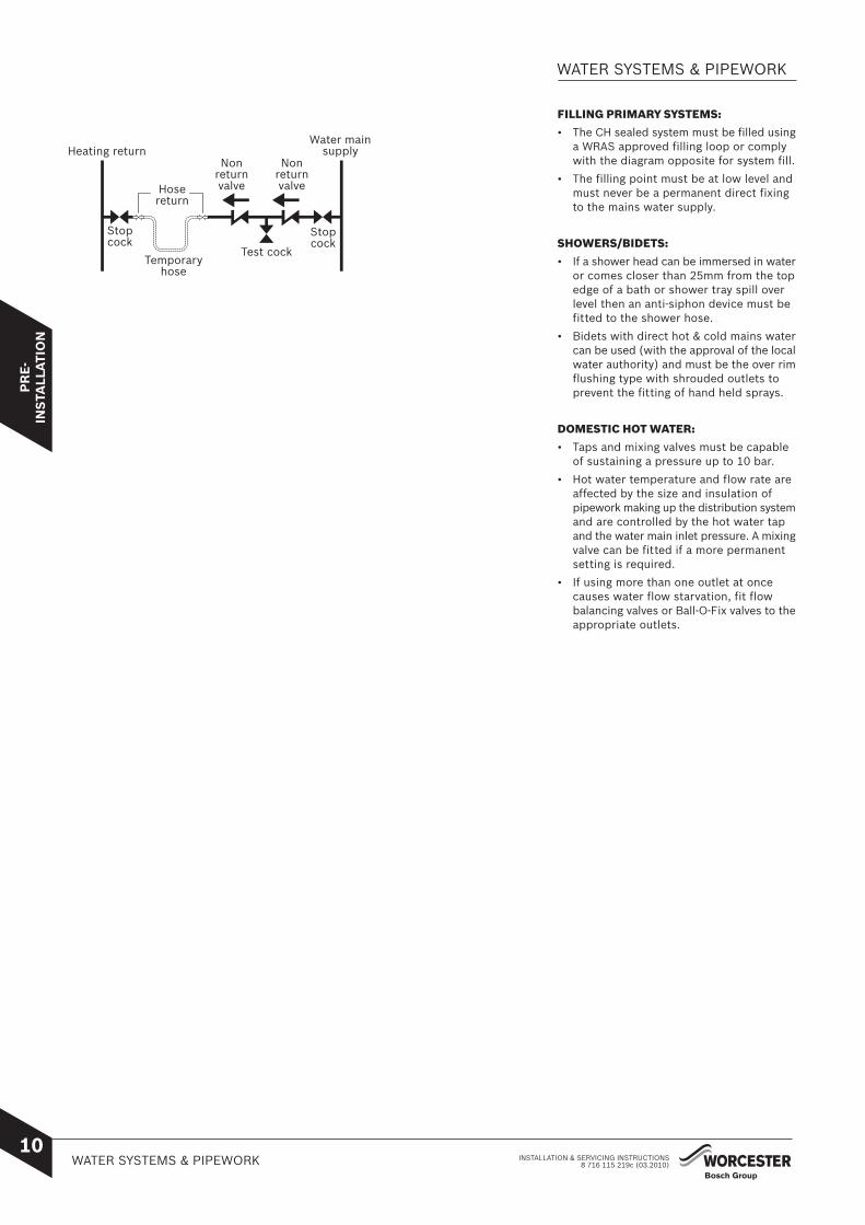
FILLING PRIMARY SYSTEMS:
• The CH sealed system must be filled usinga WRAS approved filling loop or complywith the diagram opposite for system fill.
• The filling point must be at low level andmust never be a permanent direct fixingto the mains water supply.
SHOWERS/BIDETS:
• If a shower head can be immersed in wateror comes closer than 25mm from the topedge of a bath or shower tray spill overlevel then an anti-siphon device must befitted to the shower hose.
• Bidets with direct hot & cold mains watercan be used (with the approval of the localwater authority) and must be the over rimflushing type with shrouded outlets toprevent the fitting of hand held sprays.
DOMESTIC HOT WATER:
• Taps and mixing valves must be capableof sustaining a pressure up to 10 bar.
• Hot water temperature and flow rate areaffected by the size and insulation ofpipework making up the distribution systemand are controlled by the hot water tapand the water main inlet pressure. A mixingvalve can be fitted if a more permanentsetting is required.
• If using more than one outlet at oncecauses water flow starvation, fit flowbalancing valves or Ball-O-Fix valves to theappropriate outlets.
WATER SYSTEMS & PIPEWORK
Heating return
Hosereturn
Nonreturnvalve
Nonreturnvalve
Test cock
Water mainsupply
Stopcock
Temporaryhose
Stopcock

Soil & vent stack22mmØ
minimum 450mm and up to 3 storeys
Invert
Condensate drainage pipe can be run above or below ground
25mm
Bottom of tube sealed
Limestone chippings Hole depth
400mm min.by 300 Ø
Drainage holes
22mmØ condensate drainage pipe, max external length 3 metres
Diameter 100mmmin. plastic tube
500mm min.
75 mm min.
Condensing Boiler
22mmØ
plastic pipe
75mm sink waste trap
Open end of condensate drainage pipe directly into gully below grating but above water level
Visible air break at plug hole
22 mm Ø plastic condensate drainage pipe running through the external wall
External air break
Air gap
External rain water pipe into foul water
68 mm Ø PVC-u strap on fitting
43 mm 90° M & F bend
100mm
Sink with integral overflow
Insulation or increase pipe size
Insulation or increase pipe size
Insulation orincrease pipe size
-
Fitting an external air break
Use the situation opposite when a rain water
down pipe is used to dispose of condensate
and the down pipe goes directly into an
existing sewer that carries both rainwater
and foul water.
An air break must be installed in the
32/43mm pipework, between the boiler
condensate outlet and the drainpipe, outside
the property, to avoid flooding during
adverse weather conditions.
CONDENSATE PIPEWORK:
• The condensate pipe must be a minimum of
22mm Ø plastic pipe.
• The condensate pipework must fall at
least 50 mm per metre towards the outlet
and should take the shortest practicable
route.
• The pipework must follow one of the options
shown opposite or discharge directly into a
vent stack min. 450mm above pipe invert or
into a gully below ground but above the water
level.
• Wherever possible the condensate
discharge pipe work should be routed and
terminated internally. Should this not be
possible, and the only available route is
external, the following conditions should be
observed:
External pipe work
- Pipe work length should be kept to a
minimum and the route as vertical as
possible.
- Where pipe work is subjected to
extreme cold or wind chill, a weather
proof insulation should be used.
Alternatively the condensate pipework
could be increased to a minimum
diameter of 32mm without the
requirement to insulate.he pipe run
IMPORTANT:
• Ensure there are no
blockages in the pipe run
• Care should be taken when
siting a soak-away to avoid
obstructing existing services
• Condensate waste must not
be terminated into a septic
tank or cesspit
Condensate soakaway
The condensate drainage pipe may be run
above or below the ground to the soakaway.
The example shown opposite runs above
ground level.
The soakaway must use a 100mm diameter
plastic tube with two rows of three 12 mm
holes on 25 mm centres and 50 mm from
the bottom of the tube. The holes must face
away from the house.
The tube must be surrounded by at least
100 mm of limestone chippings to a depth
of 400mm.
Condensing Boiler
Condensing Boiler
CONDENSATE PIPEWORK
PR
E-
INS
TALL
ATI
ON
INSTALLATION & SERVICING INSTRUCTIONS8 716 115 219c (03.2010)
11CONDENSATE
PIPEWORK

PR
E-
INS
TALL
ATI
ON
INSTALLATION & SERVICING INSTRUCTIONS12
8 716 115 219c (03.2010)PRESSURE RELIEF PIPEWORK
A
B
A
• The pressure relief drain pipe (A) shouldbe at least 15mm diameter copper pipeand run downwards away from the boilerand discharge away from any electrics orother hazard, preferably to an externaldrain or soakaway.
• Pipe (A) should be finished with a partialbend, near the outlet to face the externalwall(as shown) to help prevent freezing.
A - Drain pipe.
B - Outside wall.
PRESSURE RELIEF PIPEWORK
IMPORTANT: Debris from the systemcan damage the boiler and reduceefficiency. Failure to comply with theguidelines for the use of water treatmentwith the appliance will invalidate theappliance warranty.

PR
E-
INS
TALL
ATI
ON
INSTALLATION & SERVICING INSTRUCTIONS BOILER LOCATION & CLEARANCES8 716 115 219c (03.2010)
13
• This boiler is only suitable for installinginternally within a property at a suitablelocation onto a fixed rigid non-combustiblesurface at least the same size as the boilerand capable of supporting the boiler weight.
• The boiler is not suitable for external installationunless a suitable enclosure is provided.
• THIS BOILER IS NOT SUITABLE FOR ROOFSPACE INSTALLATION.
COMMERCIAL INSTALLATION:
• If installing more than one appliance in amodular or cascade arrangement in acommercial premises, that total more than70kW, then additional ventilation is needed tocomply with the Dangerous Substances andExplosive Atmospheres Regulations (DSEAR).
Compartments:
Follow the requirements of BS6798 andBS5440 Part 2 and note:
• Minimum clearances must be maintained.
• An access door is required to install, serviceand maintain the boiler and any ancillaryequipment.
• If fitting the boiler into an airing cupboarduse a non-combustible perforated material(maximum hole sizes of 13mm) to separatethe boiler from the airing space.
1: INSTALLATION CLEARANCES:
Diagram '1' shows the minimum spacerequired to install the boiler only.
2: SERVICE CLEARANCES:
Diagram '2' opposite shows the minimumspace required to service the boiler only.25mm to an removable door.
3: UNVENTED COMPARTMENTCLEARANCES:
Diagram '3' shows the minimum spacerequired to install and service the boiler insidean unvented compartment.
*Space required for unvented areas with aremovable door or panel.
**This space can be reduced to 50mm for oneside only as long as both the side clearancesadd up to the total of both the sidemeasurements shown or more.
BOILER LOCATION &CLEARANCES
600mm
800mm 800mm
900m
m
50mm
100mm**
100mm**
200mm*
600mm
5mm
5mm
610mm1200mm
600mm
15mm
5mm
5mm
610mm1200mm
1: INSTALLATION CLEARANCES
1450
mm
865m
m2: SERVICE / VENTED
CUPBOARD CLEARANCES
3: UNVENTEDCOMPARTMENT CLEARANCES *250mm

PR
E-
INS
TALL
ATI
ON
INSTALLATION & SERVICING INSTRUCTIONSBOILER LOCATION & CLEARANCES 8 716 115 219c (03.2010)
14
BOILER LOCATION &CLEARANCES
600mm
2250mm
600mm
2250mm
600mm
600mm radius
750mm
750mm
2250mm
m2250m
1 1
22
1 1
22
6: BATHROOMS:
IMPORTANT:Any switch or appliance control using mains electricity must not be within reach of a person using the bath or shower.
Electrical switches, fused spurs and socket outlets must not be situated in the bathroom.
A boiler fitted with a non-mechanical timer or with no timer can be installed in zone 2 or outside the shaded area.
A boiler with a mechanical timer or RF mechanical timer with a room thermostat must only installed outside the shaded area.
Additional RCD (Residual Current Device) protection may be required.
Refer to the latest IEE wiring regulations.
4: AIRING CUPBOARD CLEARANCES:
Diagram 'd' opposite shows the minimumspace required to install and service the boilerwithin an airing cupboard.
5: VENTING COMPARTMENTS:
If the clearances are less than those statedfor options '3' & '4' (above) then ventilationmust be provided as described in BS 5440.
A minimum of 2 air vents (C) of equal size mustbe fitted, one at low level and another at highlevel on the same wall using the same air forcirculation.
Minimum free area required for venting:
For area directly from outside:
440CDi 155cm2 per vent.
550CDi 220cm2 per vent.
For air from internal space/room:
440CDi 310cm2 per vent.
550CDi 440cm2 per vent.
25mm 100mm
200mm
100mm
25mm
625mm 800mm
C
B
D
1050
mm
5: VENTINGCOMPARTMENTS
4: AIRING CUPBOARDCLEARANCES

PR
E-
INS
TALL
ATI
ON
INSTALLATION & SERVICING INSTRUCTIONS8 716 115 219c (03.2010)
15MOUNTING FRAME CONNECTIONS
CONNECTIONS:
Water: 22mm compression fittings
Gas: 22mm compression fitting.
PRE-PLUMBING:
• With the mounting frame (A) installed,pipework can be connected to the valveson the plumbing manifold.
• The system can be filled (without theboiler being connected) using an optionalcharging link assembly (B).
• The valves can be closed enabling theDHW and CH systems to be tested.
• The boiler can be installed at a later date.
RUNNING PIPES BEHIND THE BOILER:
• The frame should sit against the wall (notthe skirting board) with enough room forthe pipework.
• Do not cross a pipe over another.
• The area around a rear flue outlet mustbe avoided.
MOUNTING FRAMECONNECTIONS
A
B (Optional)
C

PR
E-
INS
TALL
ATI
ON
INSTALLATION & SERVICING INSTRUCTIONS16
TERMINAL OUTLET POSITIONS 8 716 115 219c (03.2010)
TERMINAL OUTLET POSITIONS
Key to illustration
1. Flue clearance must be at least 300mm from the ground. Terminal guards must be fitted if the flue is less than 2 metres from the ground or if a person could come into contact with the flue terminal.
2. 600mm distance to a boundary, unless it will cause a nuisance.BS 5440: Part 1 recommends that care is taken when sitingterminals in relation to boundaries.
3. 600mm minimum clearance from a skylight to a vertical flue.
4. Vertical flue clearance 500mm to non-combustible buildingmaterial, and 1,500mm clearance to combustible buildingmaterial.
5. The dimension below eaves, gutters,pipes and drains canbe reduced to 25 mm, as long as the flue terminal is extendedto clear any overhang. Any external flue joints must be sealedwith suitable silicon sealent.
6. 500mm clearance to any vertical structure on a roof, 600mm to room sealed flue or 1,500mm to an open flue.
7. 1,500mm between a vertical flue terminal and a window or dormer window.
8. 400mm from a pitched roof or in regions with heavy snow fall 500mm.
9. The flue cannot be lower than 1,000mm from the top of a light well due to the build up of combustion products.
10. 2,000mm below a Velux window, 600mm above or to either side of the Velux window.
11. 200mm below eaves and 75mm below gutters, pipes and drains.
12. 1,200mm between terminals facing each other.
13. 300mm to an internal or external corner.
14. The dimension below eaves, balconies and car ports can be reduced to 25 mm, as long as the flue terminal is extended to clear any overhang. Installations in car ports are not recommended. Any external flue joints must be sealed with suitable silicon sealent.
15. 300mm above, below and either side of an opening door, air vent or opening window.
NOTE: All measurements are the minimum clearances required. Terminals must be positioned so to avoid combustion products entering the building.
DormerWindow
Boundary
Drainpipe
Velux Window
3
2
4
6
8
11
1213
7
1
500 600 500
500
300
300
300
300
30025
200
1,500
1,500
1,200
300
600
Window
15
910
251425 5
All measurements in millimetres
400

PR
E-
INS
TALL
ATI
ON
INSTALLATION & SERVICING INSTRUCTIONS17
TERMINAL OUTLET POSITIONS8 716 115 219c (03.2010)
Key to illustration
1. 600 mm distance to a boundary, unless it will cause a nuisance. BS 5440: Part 1 recomends that care is taken when siting terminals in relation to boundaries.
2. Internal/external corners the air intake can be reduced to150mm providing the flue exhaust outlet has a 300mm clearance.
3. The flue cannot be lower than 1,000mm from the top of the light well due to the build up of combustion products.
4. 1,200mm between air intake and facing terminal.
5. Clearance no less than 200mm from the lowest point of the balcony or overhang, installations in car ports are not recommended.
6. 1,200mm from an opening in a car port on the same wall i.e. door or window leading into dwelling. 600mm to a surface facing a terminal.
7. Using a Plume Management Kit the air intake measurement can be reduced to 150mm providing the flue exhaust outlet has a 300mm clearance.
Plume kits running horizontally must have a 10 degree fall back to the boiler for proper disposal of condensate.
For details on specific lengths see relevant boiler Technical & Specification manual.
8. This allows some basic plume options on a standard telescopic horizontal flue terminal. 300mm minimum clearances to a opening e.g. window.
However the minimum clearance to an opening in the direction to which the plume is directed in, should be increased to 1,500mm.
Where the flue is less than 150mm to a drain pipe & the plume deflector is used it should not be directed towards it.
NOTE: All measurements are the minimum clearances required. Terminals must be positioned so to avoid combustion products entering the building.
PLUME MANAGEMENT KIT POSITIONS
Door
Balcony
Flue Exhaust
Outlet
Air Intake
Boundary
Drainpipe
3
2
4
56
7
1
200 200
200
200
200
300
300300
300
1,200
150
150
150 150150
600
All measurements in millimetres
Window Window
25
25
180°
Plume management deflector:
8
Window

The diagrams (opposite) show thecomponents used and the maximum fluelength for each configuration of Ø100mm andØ125mm flues.
• Only straight flue sections can be reducedin length by cutting.
• The Ø100mm horizontal flue terminal canbe fitted from inside or outside thebuilding.
IMPORTANT:
All horizontal sections must rise awayfrom the boiler by 52mm per metre (3°)to allow the condensate to drain backto the boiler.
A - Horizontal terminal
B - Straight flue extension
C - Flue bend 90°
D - Flue bend 45°
E - Vertical Terminal
Calculating the flue length:
Measure the total flue length (L) required,noting that the maximum straight flue lengthincluding the terminal is:
Horizontal Ø60/100mm: 4000mm
Horizontal Ø80/125mm: 13000mm
Vertical Ø60/100mm: 6400mm
Vertical Ø80/125mm: 15000mm
Then reduce the total straight flue length foreach extra flue bend (excluding the flue elbow)by:
2000mm for 90°
1000mm for 45°
Flue Extension lengths:
Horizontal & Vertical Ø60/100mm: 950mm
Horizontal & Vertical Ø80/125mm: 950mm
Flue Terminal lengths:
Horizontal Ø60/100mm: 530mm
Horizontal Ø80/125mm: 1200mm
Vertical Ø60/100mm: 1140mm
Vertical Ø80/125mm: 1365mm
PR
E-
INS
TALL
ATI
ON
INSTALLATION & SERVICING INSTRUCTIONS18
ROOM SEALED FLUE OPTIONS 8 716 115 219c (03.2010)
ROOM SEALED FLUE OPTIONS
B
B
C
B
D D
B
C C
B
C C
B
C C C
E
B
D
D
C
E
B
C
L= Ø100mm 140 - 530mmL= Ø125mm 350 - 1200mm
L
Ø100mm x4Ø125mm x12
L
L= Ø100mm 310 - 4000mmL= Ø125mm 350 - 13000mm
L= Ø100mm 2000mmL= Ø125mm 11000mm
Ø100mm x2Ø125mm x10
L
Ø100mm x2Ø125mm x10
L=Ø100mm 2000mmL=Ø125mm 11000mm
L= Ø125mm 9000mm
Ø125mm x8
L
L= Ø125mm 9000mm
Ø125mm x8
L
L= Ø125mm 7000mm
Ø125mm x6
L
L= Ø100mm 4400mmL= Ø125mm 13000mm
Ø100mm x4Ø125mm x12
L
L=Ø100mm 2400mmL=Ø125mm 11000mm
Ø100mm x2Ø125mm x10
L
L
A
A
A
A
A
A
A
EDC
B
Min.120mm
Min.120mm
Min.120mm
Min.120mm
A

INS
TALL
ATI
ON
INSTALLATION & SERVICING INSTRUCTIONS19
UNPACKING THE BOILER8 716 115 219c (03.2010)
IMPORTANT: All the previous Pre-Installation sections must be read andrequirements met before starting boiler or flue installation.
Take care not to damage the boiler panels orthe floor and note that the boiler may containsome water due to factory testing.
Unpacking:
1 Undo the ties securing the carton to thepallet
If a sharp implement is used, care must betaken not to pierce the carton or cause injury.
2 Before removing the carton it is advisedthat the top flaps are opened and theancillary items (A, B, C & D) are removedand set to one side.
3 The carton can now be lifted off theboiler.
Remove the plastic bag protecting theboiler surfaces and place safely away fromthe working area.
Remove 2 screws at the rear of the boardsecuring the board to the pallet.
Slide the boiler and board off the pallet.
4 Grip the outer sides of the front panelpull and lift away from retaining lugs.
Remove securing screw, at the front ofthe boiler, from the pallet.
Remove remaining screws, at the rear ofthe boiler, from the pallet.
The boiler is mounted on small wheelsand two people are recommended to movethe boiler from the board taking care notto damage the panels or the floor.
5 Remove the rubber plug (E) from theboiler pipework by pulling down.
At all times the correct method for handlingheavy objects should be strictly observed.
GENERAL HANDLING GUIDELINES:
Lift only a manageable weight, or ask forhelp.
When lifting, bend the knees, and keepthe back straight and feet apart.
Do not lift and twist at the same time.
Lift and carry items close to the body
Wear protective clothing and gloves toprotect from any sharp edges
THIS BOILER IS NOT SUITABLE FOR ROOFSPACE INSTALLATION.
A - Mounting frame
B - Installation pack
C - Literature pack
D - Condensate waste pipe & non-return valve
UNPACKING THE BOILER
1
2
A
B C
3
4E
D

INS
TALL
ATI
ON
INSTALLATION & SERVICING INSTRUCTIONS20
MOUNTING FRAME FIXING &FLUE OPENING
8 716 115 219c (03.2010)
MOUNTING FRAME FIXING &FLUE OPENING
All dimensions in mm
2
13
4
38mm
ZX
Y
123 343
123
743*
+13
X Y Z
112 65 98.5 65 65 81
CB A
A
D
E
267
B B
20
F DD
CAUTION: Ensure there are no pipes,electric cables, damp proof course or otherhazards before drilling.
SAFETY:
All relevant safety precautions must beundertaken. Protective clothing, footwear,gloves and safety goggles must be worn asappropriate.
MOUNTING FRAME/PIPEWORK POSITIONS:
A - Mounting frame.
B - Manifold connections.
C - Mounting frame fixing point.
D - Wall.
E - Gas and water pipework (not supplied).
F - Boiler.
FIXING THE MOUNTING FRAME:
Position the mounting frame (A) on thefloor against the wall with manifoldconnections (B) facing away from the wall(D) ensuring there is enough space for thepipework (E).
Allow the minimum space from each sideof the frame (A) for the boiler overhang (F)and minimum service clearance, as shown.
Ensure the mounting frame is level andmark fixing points (C).
Secure mounting frame (A) to the floorusing appropriate fixings (not supplied).
Clear any debris from the site.
FLUE OPENING:
Follow the diagram opposite to mark thecentre of the flue (1, & 2) for rear opening,(2 & 3) for side opening or (1 & 4) for topopening.
Measurements shown include the minimumservice clearances.
NOTE: All horizontal flue sections must rise away from the boiler by 52mm per meter to ensure that condensate flows back into the boiler for safe discharge via the condensate waste pipe.
Cover the mounting frame manifoldassembly (A) to protect the manifoldconnections.
Make an opening (X or Z) through the wallusing a core drill or similar at a size relativeto the wall thickness as shown below:
Wall Flue opening Flue openingthickness 60/100mmØ 80/125mmØ
150 - 240mm 127mmØ 152mmØ240 - 330mm 127mmØ 152mmØ330 - 420mm 127mmØ 162mmØ420 - 500mm 140mmØ 162mmØWhere the flue terminal can only be fittedfrom inside the building, increase the openingto 150mmØ to allow the optional weathercollar to fit through the opening for 60/100flue.
Clear away any debris.

INS
TALL
ATI
ON
INSTALLATION & SERVICING INSTRUCTIONS21
MOUNTING FRAME CONNECTIONS8 716 115 219c (03.2010)
CAUTION: ISOLATE THE MAINS GASSUPPLY BEFORE STARTING ANY WORKAND OBSERVE ALL RELEVANT SAFETYPRECAUTIONS.
GAS AND WATER CONNECTIONS:
Ensure all pipework is clean and eachpipe is in the correct position as shownopposite.
Push in each pipe in turn and tighten thefitting to secure.
A - CH flow (22mm)
B - DHW flow (22mm)
C - Gas inlet (22mm)
D - Mains water inlet (22mm)
E - CH return (22mm)
F - Mounting frame.
MOUNTING FRAMECONNECTIONS
A BC D
E
F

INS
TALL
ATI
ON
INSTALLATION & SERVICING INSTRUCTIONS22
FLUE LENGTHSFLUE MEASURING & CUTTING
8 716 115 219c (03.2010)
HORIZONTAL FLUE:
(60/100mm diameter)
For vertical flues and 80/125mmØ horizontalflues, please refer to separate Flue manuals.
Ø60/100mm HORIZONTAL TELESCOPICFLUE LENGTHS:
The maximum effective straight flue lengths(L) are stated opposite for the relevantappliance and must not be exceeded.
1 Measure the total straight length (L)along the flue route, then add the followingto length (L) to check the maximum fluelength is not exceeded:
2000mm for each extra 90° bend.
1000mm for each extra 45° bend.
Do not exceed the maximum straightlength for a horizontal Ø60/100mm flueor a Ø60mm plume management system(if used) as stated in this InstructionManual or Flue Manual.
Cutting the flue to an exact measure is notnormally required as the telescopic flue terminalallows for adjustment.
1 Measure the flue length (L) from theboiler inner case (A) along the flue routeto the outside wall (D).
Note, the terminal end projects beyond theoutside wall by the distance shown opposite.
A - Boiler inner case.
B - Flue connector.
C - Flue extension tube socket.
D - Outside wall.
E - Aluminium tape over terminal screwedjoint.
FLUE MEASURING & CUTTING
FLUE LENGTHS
10 CUT LENGTH WITH ONEEXTENSION = L - 410mm
L
A
DC
400
All dimensions in mm.
E
1 Example with one extension tube:
110
440CDi 4000mm
550CDi 4000mm
L max.Appliance description
EFFECTIVE MAXIMUM STRAIGHT FLUELENGTHS for Ø60/100mm Telescopic flue:
L1
B
INS
TALL
ATI
ON
INSTALLATION & SERVICING INSTRUCTIONS23
FLUE MEASURING & CUTTING8 716 115 219c (03.2010)
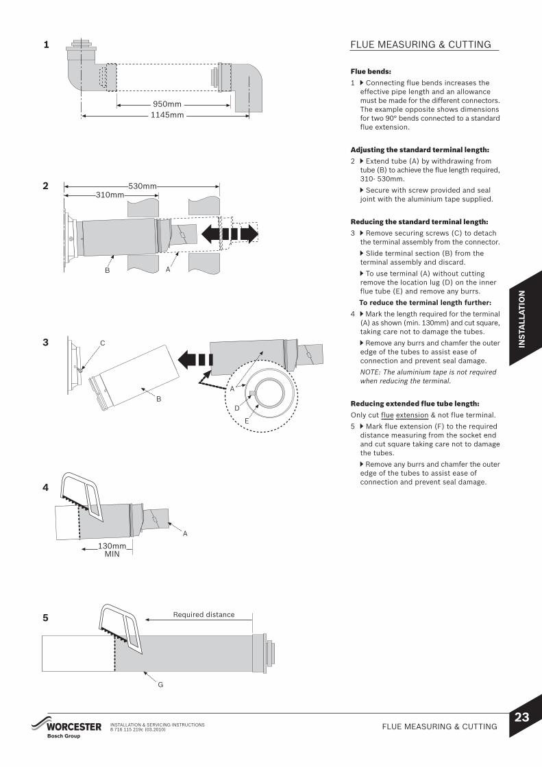
Flue bends:
1 Connecting flue bends increases theeffective pipe length and an allowancemust be made for the different connectors.The example opposite shows dimensionsfor two 90° bends connected to a standardflue extension.
Adjusting the standard terminal length:
2 Extend tube (A) by withdrawing fromtube (B) to achieve the flue length required,310- 530mm.
Secure with screw provided and sealjoint with the aluminium tape supplied.
Reducing the standard terminal length:
3 Remove securing screws (C) to detachthe terminal assembly from the connector.
Slide terminal section (B) from theterminal assembly and discard.
To use terminal (A) without cuttingremove the location lug (D) on the innerflue tube (E) and remove any burrs.
To reduce the terminal length further:
4 Mark the length required for the terminal(A) as shown (min. 130mm) and cut square,taking care not to damage the tubes.
Remove any burrs and chamfer the outeredge of the tubes to assist ease ofconnection and prevent seal damage.
NOTE: The aluminium tape is not requiredwhen reducing the terminal.
Reducing extended flue tube length:
Only cut flue extension & not flue terminal.
5 Mark flue extension (F) to the requireddistance measuring from the socket endand cut square taking care not to damagethe tubes.
Remove any burrs and chamfer the outeredge of the tubes to assist ease ofconnection and prevent seal damage.
FLUE MEASURING & CUTTING
2
3
A
BA
C
4
A
G
Required distance
310mm530mm
130mmMIN
D
E
B
5
1145mm 950mm
1

INS
TALL
ATI
ON
INSTALLATION & SERVICING INSTRUCTIONS24
FLUE MEASURING & CUTTING 8 716 115 219c (03.2010)
FLUE MEASURING & CUTTING
FLUE OUTLETS (L or P):
1 Remove seal (B) from flue adaptor (A).
2 Cut square to mark, as shown, deburrand clean.
3 Replace seal (B).
L
PL
L
P
A B
A B
B
1
2
3
1
3
2

INS
TALL
ATI
ON
INSTALLATION & SERVICING INSTRUCTIONS25
FLUE INSTALLATION8 716 115 219c (03.2010)
FLUE INSTALLATION
1 Remove retaining screw (A) to swingcontrol panel assembly (B) outwards toits full extent.
2 Remove screws (C) from inside of casing.
Lift front of top panel (D) to release.
Pull forwards to disengage rear retainer(E), then lift panel (D) away from boiler.
3 Pull clip (F) outwards to release theexpansion vessel(G).
4 Swing expansion vessel (G) outwards.
Note: for easier access to the inner case, theexpansion vessel can be unhooked (by removingthe retaining screw on the hinge) lowered andmoved to the side. Take care not to overstretchthe flexible pipe connections.
5 Release four screws (H) to remove theinner case cover ( I ).
CONVERT FROM REAR FLUE OUTLET:
The boiler is supplied ready to fit a rear flueoutlet. To flue from the sides or top of the boiler,follow the procedure below:
1 Remove and discard the required side ortop 'knock-out' panel (A) from the outercasing (B).
2 Remove the flue outlet blanking platecomprising: cover (D) and gasket (E) fromthe inner casing (C) by removing the threescrews (F).
3 Refit the outlet blanking plate over the rear flue outlet.
A
1B
C 2
D
E
3
F
G
5
H
I
A
D
C
A
B
F
E
AB
1
2

INS
TALL
ATI
ON
INSTALLATION & SERVICING INSTRUCTIONS26
STANDARD FLUE INSTALLATION 8 716 115 219c (03.2010)
STANDARD FLUE INSTALLATION
TOP
110mm
3
B
K
G
F
H
E
E
GH
J
C
4
5
6
A
Clip
C
B
A
2
B
1
A
TOP
TOP
NOTE: to ease assembly of the flue components,grease seals lightly with the solvent-free greasesupplied.
Check all the seals are seated properly in the groovesprovided and are in good condition.
All flue joints must be sealed to prevent leakage ofcondensate and flue products.
Installing the standard flue:
1 Set the flue terminal (B) to the distancerequired, secure with screw and seal jointwith the aluminium tape supplied.
2 Slide the inner wall seal (C) onto theterminal (B) as shown.
If fitting from inside the building; slidethe outer wall seal (K) onto terminal (B).
3 Position terminal (B) through the flueopening in the wall to the outside of thebuilding by the distance shown and thenpull back to create a seal.
The flue terminal (B) MUST be fittedwith the label marked 'TOP' uppermostto allow the correct fit and use of theplume management system.
If fitting from the outside of the building;slide the outer wall seal (K) onto terminal(B) to fit against the outer wall and thenpull back to create a seal.
4 Roll the boiler into position on the floormounting frame.
Position connector (A) with the labelmarked ‘TOP’ uppermost to align with thethree holes in the boiler inner casing (E).
Secure using three hexagonal bolts (F).
5 Push-fit adaptor (G) into elbow (H) untilsecured by the clip.
6 Slide adaptor (G) into the inner flue tubeof terminal (B) and push elbow (H) intoflue outlet (J) until secured by the retainingclips ensuring a good seal is made.

INS
TALL
ATI
ON
INSTALLATION & SERVICING INSTRUCTIONS27
EXTENDED FLUE INSTALLATION8 716 115 219c (03.2010)
EXTENDED FLUE INSTALLATION
TOP
M
110mm
10
N
8
6
9 M
KC
B B
L
K
BK
B
E
GH
J
AD
D
F B
E
1
2
3
CB
1m2m
52mm 104mm
5
7
A
C
TOP
TOP
G
H
4Clip
NOTE: to ease assembly of the flue components,grease seals lightly with the solvent-free greasesupplied.
Check all the seals are seated properly in the groovesprovided and are in good condition.
All flue joints must be sealed to prevent leakage ofcondensate and flue products.
All horizontal flue sections must rise byat least 52mm for each metre away fromthe boiler to ensure that condensateflows back into the boiler for safedischarge via the condensate waste pipe.
Installing an extended flue:
1 Slide a support clamp (C) (not supplied) onto a flue extension (B) as shown.
2 Secure connector (A) to flue extension(B) using two screws (D).
3 Support the weight of flue extension (B)and position connector (A) with labelmarked ‘TOP’ uppermost to align with thethree holes in the boiler inner casing (E).
Secure using three hexagonal bolts (F).
4 Push-fit adaptor (G) into elbow (H) untilsecured by the clip.
5 Push-fit the adaptor (G) into the innerflue extension (B) and push elbow (H) intoflue outlet (J) until secured by the retainingclips.
6 Slide a support clamp (C) (not supplied)onto additional flue extensions (B).
Working from the boiler, fit theextension/s with support clamp/s asrequired, to take the weight of the flue.
Drill two holes (180° apart if possible)through the outer flue tube of eachextension taking care NOT to drill the innerflue tube and secure with screws (K) asshown.
7 Slide the inner wall seal (L) onto terminal(N).
If fitting from inside the building; slidethe outer wall seal (M) onto terminal (N)as shown.
8 Position terminal assembly (N) throughthe flue opening in the wall to the outsideof the building by the distance shown andthen pull back to create a seal..
9 Fit terminal assembly (N) into the lastextension (B).
The flue terminal (N) MUST be fittedwith the label 'TOP' uppermost to allowthe correct fit and use of the plumemanagement system.
Drill the outer flue tubes and fix withscrews (K).
10 If fitting from the outside of the building;slide the outer wall seal (M) onto terminal(N).

INS
TALL
ATI
ON
INSTALLATION & SERVICING INSTRUCTIONS28
FLUE TERMINAL PLUME MANAGEMENT 8 716 115 219c (03.2010)
FLUE TERMINAL PLUMEMANAGEMENT
The flue discharge can be redirected allowingsome plume management control, alternatively,a complete plume management system can befitted to the flue terminal.
Redirecting the flue discharge:
Important: should you wish to use theplume deflector please use the additionalgrease enclosed to ensure that anadequate seal is retained.
1 Remove screws (A) and terminal end (B).
2 Spread the extra grease supplied intothe groove that runs around the terminaloutlet (C) to ensure a good seal is retained.
3 Rotate the detached end section (B) toplume deflecting position, as shown andrefit using screws (A).
4 Loosen screws (D) and rotate the terminalend (B & C) to redirect the plume.
DO NOT rotate the complete flue terminalassembly.
Retighten screws (D) to secure in therequired position.
NOTE: the flue terminal outlet has built-instops to limit rotation for horizontal fluingto allow condensate to run back into theboiler for safe disposal. Do not attempt toforce beyond the limit stops.
1
A
B
B
A
3
B
4
D
±80°
2
C
C

INS
TALL
ATI
ON
INSTALLATION & SERVICING INSTRUCTIONS
CONDENSATE, GAS & WATERCONNECTIONS
29CONDENSATE, GAS & WATER CONNECTIONS8 716 115 219c (03.2010)
CONDENSATE CONNECTION:
The condensate pump (G) fills up andperiodically discharges through the flexiblecondensate pipe (H) between 200mm to4500mm from floor level. After this point thecondensate flows, due to gravity, down the21.5mm plastic pipe to the outlet.
Fit the bayonet connector on the end ofthe condensate waste pipe to thecondensate pump. Push down and rotateclockwise until the connector is locked. Route and secure condensate waste pipe
(H) with clips supplied to prevent kinkingor restriction.
Cut off any excess pipe (H).
Fit the condensate waste pipe (H) toadaptor (K) and secure with clip (J).
Connect adaptor (K) to 21.5mm plasticpipe and terminate into an internal wastetrap.
(See Pre-Installation section for condensatepipework running from the adaptor (K) tothe discharge outlet).
Never terminate or discharge into anyopen source, including; sink, bath, shower,bidet, toilet etc.
Note: Any external condensate pipework should be protected with weather resistant insulation to help prevent freezing.
The flexible pipe supplied can only be used inside the property.
CAUTION: ISOLATE THE MAINS GAS ANDWATER SUPPLY BEFORE STARTING ANYWORK AND OBSERVE ALL RELEVANTSAFETY PRECAUTIONS.
GAS AND WATER CONNECTIONS:
Remove the transit bung (L) from the gas& water connections (A, B, C, D & E) onthe boiler and mounting frame.
Note: that surplus water may be present dueto factory testing.
Ensure the area is clear of debris andmanoeuvre the boiler rear wheels onto theouter rails of the mounting frame (F).
Take care when moving the boiler toposition the front wheels onto the railsand align the gas/water connections andthe flue.
Secure boiler to mounting frame (F) withscrew (M)
Place the 5 larger valve sealing washers(shown shaded) onto valves A, B, C, D &E.
Ensure all pipework is clean.
Tighten the compression fittings tosecure:
A - CH flow (22mm).
B - DHW flow (22mm).
C - Gas inlet (22mm).
D - Mains water inlet (22mm).
E - CH return (22mm).
HJ
K
Max. 4500mmH
Min. 200mm
G
ED
CB
A
F
M
F
H
L

INS
TALL
ATI
ON
INSTALLATION & SERVICING INSTRUCTIONS30
PRESSURE RELIEF VALVE OUTLET 8 716 115 219c (03.2010)
PRESSURE RELIEF VALVEOUTLET
Fitting the pressure relief valve drain pipe:
Connect a length of 15mm copper pipe(A) to the P.R.V drain pipe (B).
The P.R.V drain pipe (B) should be at least15mm diameter and run down away fromany electrics or other hazard.
IMPORTANT: The pressure relief valveis a safety device for the boiler and ifactivated may discharge boiling wateror steam through the P.R.V drain pipe.
Auto air vent:
Remove the auto air vent cap (C) anddiscard.
B
C
A
C

NOTE:
The mains electrical supply to the boiler andsystem wiring centre must be common andthrough either a common fused double poleisolator or a fused three pin plug andunswitched socket.
The isolator shall be situated next to theboiler for new systems and, wherepracticable, replacement boilers.
The isolator must have a contact separationof 3mm minimum between all poles. Anysystem connected to the boiler must nothave a separate electrical supply.
External fuse 3 Amps.
When stripping wires ensure copper strandsdo not fall into the control box.
Access to electrical connections:
Remove boiler casing to access control panel.
1 Remove screw (A) and swing the control panel into the service position.
2 Remove the three screws (B) in the control panel and remove the connections cover.
3 Unclip cable clamp (C).
4 Cut off the tapered cable entry to suit the cable diameter.
5 Unscrew cable retaining screw (D). Run the cable through the cable clamp (C) ensuring there is ample cable to reach the connectors. Tighten the cable retaining screw D to secure the cable and replace clamp C into the control panel.
6 Mains power 230 Volt connection ST10:
Separate wires from cable end and strip to 6mm
Connect LIVE wire to terminal L
Connect NEUTRAL wire to terminal N
Connect EARTH wire to connector
NOTE: Make the EARTH wire longer so that if the cable is snagged, the EARTH wire is the last to be pulled out.
7 Optional frost thermostat connection ST6:
Connect frost thermostat supply wire to terminal Fs
Connect frost thermostat return wire to terminal FR
8 230V room thermostat and/or external timer ST10:
Remove link
Connect room thermostat LIVE supply to terminal Ls
Connect room thermostat LIVE return to terminal LR
Connect room thermostat NEUTRAL to terminal Ns
9 Refit all panels
Refer to manufacturers instructions whenconnecting external parts to the wiring centre.
Worcester, Bosch Group cannot be heldresponsible for wiring errors.
ELECTRICAL
CAUTION: ISOLATE THE MAINSELECTRICITY SUPPLY BEFORE STARTINGANY WORK AND OBSERVE ALL RELEVANTSAFETY PRECAUTIONS
INS
TALL
ATI
ON
INSTALLATION & SERVICING INSTRUCTIONS31
ELECTRICAL8 716 115 219c (03.2010)
L N
L
ST10
N
E
EARTH = E
LIVE = L
NEUTRAL = N
230 V
LRLSN S
6
3 AND
/OR
L N
ST10
LRLSN S
S LN S
F R F S N P L P
FROST
THERMOSTAT
ST10
ST6
SWITCHED LIVE = S
3
4
5
6
78
6 7
20
614
56
2-0
4.1
O
C
D
D
21
A
B

CO
MM
ISS
ION
ING
INSTALLATION & SERVICING INSTRUCTIONS32
PRE-COMMISIONING CHECKS 8 716 115 219c (03.2010)
PRE-COMMISIONING CHECKS
CAUTION: ISOLATE THE MAINS SUPPLIESBEFORE STARTING ANY WORK ANDOBSERVE ALL RELEVANT SAFETYPRECAUTIONS.
1 Check that the service and water pipesare connected to the correct valve on themanifold;
A - CH flow (22mm)
B - DHW flow (22mm)
C - Gas inlet (22mm)
D - Mains water inlet (22mm)
E - CH return (22mm)
2 Check the gas type specified on theidentification plate matches that of thegas supply.
Turn on the main gas supply, check thegas pipework, connections and rectify anyleaks.
3 Check the flue is correctly fitted and theconnections are secure.
4 Check the condensate pipework iscorrectly fitted and connected.
5 Check the CH circulating pump is set to3.
Note: The CH circulating heating pump is presetto number '3' and should not be altered.
IMPORTANT: If the boiler is not to becommissioned immediately then:
after successfully completing all of thechecks and any rectification work, shutoff the gas supply and electrically isolatethe boiler.
Complete the installation part of theGuarantee Registration Card.
1
3
4
5
2
A B C D E

CO
MM
ISS
ION
ING
INSTALLATION & SERVICING INSTRUCTIONS33
FILLING THE SYSTEM8 716 115 219c (03.2010)
FILLING THE SYSTEM
1 Turn on the water main and open thesystem valves (align slot vertically).
2 Open all radiator valves.
3 Unscrew the tank drain cap and connectthe integral filling loop between the Flowvalve and the Tank drain valve.
Open the flow and tank drain valves.
Fill the system to a pressure up to 2 bar.
Close the flow valve.
4 Vent all radiators, retighten the vent whencompleted.
Check the system and correct any leaks.
5 The boiler integral expansion vessel ispre-charged to 0.75bar (equal to a statichead of 7.5m (22ft)). A Schraeder typevalve is fitted to the expansion vessel toallow for pressure adjustment if required.
If an extra expansion vessel is fitted to thecentral heating return, adjust this to thesame pressure as the appliance internalexpansion tank, refer to separate instructionswith the extra expansion vessel.
6 Briefly open the pressure relief valve totest its operation.
7 Close the tank drain valve.
Disconnect the integral filling loop.
Connect a suitable hose to the tank drainensuring safe disposal of the discharge.
Open the tank drain valve to reduce thesystem pressure to the system pressurerequired, then close.
System pressure and capacity:
1 bar 82 litres.
1.5 bar 46 litres.
Rotate the adjustable pointer on thepressure gauge to record the set systempressure.
Disconnect the hose from the tank drain.
Refit tank drain cap.

CO
MM
ISS
ION
ING
INSTALLATION & SERVICING INSTRUCTIONS34
WATER TREATMENT 8 716 115 219c (03.2010)
IMPORTANT: Debris from the system candamage the boiler and reduce efficiency.Failure to comply with the guidelines forthe use of water treatment with theappliance will invalidate the appliancewarranty.
FLUSHING (Central Heating):
Switch off the boiler.
Open vented systems only: turn off thewater to the system header tank.
Open all radiator valves/drain cocks anddrain the system while the appliance ishot.
Close drain cocks.
Add a suitable flushing agent and refillthe system at the correct strength for thesystem condition in accordance with themanufacturer's instructions.
Run the boiler/system at normal operatingtemperature for the time stated by theflushing agent manufacturer.
Drain and thoroughly flush the system toremove the flushing agent and debris.
INHIBITOR (Central Heating):
Check drain cocks are closed and allradiator valves are open.
Add a suitable* inhibitor, (or combinedinhibitor/anti-freeze if the system isexposed to freezing conditions) to theheating system in accordance with themanufacturers instructions.
The inhibitor or combined inhibitor/anti-freeze must not cause damage to thematerials within the boiler (aluminium,stainless steel, copper and brass) and anyother materials/components within thesystem.
Open vented systems only: turn on thewater to the system header tank and allowthe system to fill.
Sealed systems only: fill the system tobetween 1 and 2 bar via a WRAS approvedfilling loop.
Vent the boiler and all radiators; retightenvents when complete.
Record the date when the inhibitor wasadded to the system on the guarantee card.
NOTE:
The concentration level of inhibitor in the systemshould be checked every 12 months or soonerif system content is lost.
The addition of sealing agents to the systemwater is not recommended as this can causeproblems with deposits left in the heatexchanger.
* compatible with aluminium. The pHvalue of the system water must be lessthan 8 or the appliance guarantee willbe invalidated.
WATER TREATMENT

IMPORTANT: Never run the appliancewhen the appliance or system is emptyor unpressurised.
Switching the appliance on/off:1 Turn on mains power supply.
Turn on any external controls.
Set the TRV controls to maximum.
Set the clock/programmer to continuously ON and the room thermostat to maximum temperature.
2 Press button (A) and the power on indicator (B) illuminates blue.
3 Turn the temperature control (C) to maximum. The burner on indicator (D) illuminates green when the burner has lit.
Note: The boiler runs for 15 minutes at minimum heatingoutput to fill the condensate trap. This occurs everytime the mains supply has been interrupted.
4 If the boiler fails to light, the blue power indicator(B) and reset button (E) will flash alternately.
To reset the boiler, press and hold the resetbutton (E) for 2 seconds.
CAUTION: DO NOT PRESS THE POWERINDICATOR (B) TO RESET THE BOILER.
THE COMBUSTION FOR THE APPLIANCE IS FACTORYSET.
NO ADJUSTMENT IS REQUIRED IF THE GAS INLETPRESSURE IS CORRECT.
CHECKING THE GAS INLET PRESSURE:
The inlet pressure to the appliance must be checkedusing the following procedure:
SETTING THE BOILER TO MAXIMUM:
Press boost button (L) for ten seconds and set temperature to maximum.
The boost button will illuminate continually.
MEASURING THE INLET PRESSURE:
Slacken the screw in the inlet pressure test point and connect a manometer.
Measure the pressure with the boiler running at maximum.
Check the gas supply working pressure at the gas valve inlet point:
N.G. minimum 17-19 mbar, nominal 18 mbar
L.P.G. 35-39 mbar, nominal 37 mbar
The gas rate should be measured at the gas meter after 10 minutes operation at maximum. See Technical Data section at the front of this manual.
(L.P.G.) where a gas meter is not available the CO/CO2 must be checked to units shown in “Setting the air/gas ratio” section.
Ensure inlet pressure is satisfactory with all other gas appliances working.
Replace controls cover.
NOTE: this boiler is designed with a differential of 20° C across the heating system.
IMPORTANT: Do not continuecommissioning until the correct gas inletpressure is achieved.
If pressure is satisfactory press the boost button again and the boiler will return to normal operation.
If left in service mode the control will return to normal operation after 15 minutes.
Reseal the screw in the gas inlet pressure test point.
CO
MM
ISS
ION
ING
INSTALLATION & SERVICING INSTRUCTIONS35
STARTING THE APPLIANCE8 716 115 219c (03.2010)
STARTING THE APPLIANCEA
D
F
L
J
C
B
I
E
H
M
G
K
A - MASTER SWITCH FOR ON/OFF
B - MAINS ON/OFF INDICATOR + FAULT DIAGNOSTIC LIGHT
C - CENTRAL HEATING TEMPERATURE CONTROL
D - BURNER ON INDICATOR LIGHT (GREEN)
E - FAULT RESET BUTTON
F - SERVICE BUTTON
G - DOMESTIC HOT WATER TEMPERATURE CONTROL
H - ECO BUTTON (DOMESTIC HOT WATER PRE-HEAT ON/OFF)
I - SYSTEM PRESSURE GAUGE
J - POSITION FOR OPTIONAL PROGRAMMER
K - DISPLAY
L - CENTRAL HEATING BOOST BUTTON
M- NOT USED
1 2
3
A
B
C
D
4
B
E

CO
MM
ISS
ION
ING
INSTALLATION & SERVICING INSTRUCTIONS36
FINISHING COMMISSIONING 8 716 115 219c (03.2010)
FINISHING COMMISSIONING
NOTE:At the time of commissioning, complete allrelevant sections of the Benchmark Checklistlocated on the inside back pages of thisdocument.
1 Engage top panel (A) onto rear retainers(B) and lower front of panel into position.
Secure with screws (C).
2 Swing control panel assembly (D) intothe boiler.
Secure with screw (E).
3 Locate bottom corners of the front panel(F) into retainers (G).
Push top of door to engage clips.
HANDOVER:
Complete the Benchmark log book at therear of the manual.
Set up the controls and show the user howto operate all the controls shown in theUser Guide.
Instruct the customer how to repressurisethe system.
If the appliance is unused and exposed tofreezing conditions, advise the customerof the precautions necessary to preventdamage to the boiler, system and building.
In the event of the appliance beinginoperative, isolate the boiler and drainthe system and boiler.
1
C
A
B
2
D
E
3
F
G

SE
RV
ICIN
G&
SP
AR
ES
INSTALLATION & SERVICING INSTRUCTIONS37
INSPECTION & SERVICE8 716 115 219c (03.2010)
INSPECTION & SERVICE
IMPORTANT: Any service work must becarried out by competent registeredengineers, such as British Gas or otherGAS SAFE registered personnel.
NOTE: After servicing, complete the relevant Service Interval Record section of the Benchmark Checklist located on the inside back pages of this document.
NOTE: A service must NOT be attempted if a CO/CO2 analyser is NOT available.
• To ensure the continued efficient operationof the appliance it must be checked atregular intervals.
• The frequency of servicing will dependupon the particular installation conditionsand usage however, an annual service isrecommended.
• The extent of the service required by theappliance is determined by the operatingcondition of the appliance when tested byfully qualified engineers.
SERVICE FUNCTION:
Setting boiler to maximum:
Note: when running in the heating boost mode,the boiler will operate both the Central Heatingand DHW circuits. This is to allow sufficienttime for setting procedure.
It will be necessary to run water through theDHW circuit to ensure that the boiler will notcycle on low heating demands.
Press and HOLD central heating boostbutton (L) for 10 seconds and set CentralHeating temperature to maximum.
The central heating boost button willilluminate continually.
The boiler will stay in this mode for 15minutes unless the central heating boostbutton is pressed again.
CAUTION: TURN OFF THE GAS SUPPLY AND ISOLATE THE MAINS SUPPLIESBEFORE STARTING ANY WORK AND OBSERVE ALL RELEVANT SAFETY
IMPORTANT: AFTER REPLACEMENT OF ANY COMPONENTS ALWAYS CHECK FORGAS TIGHTNESS WHERE RELEVANT AND CARRY OUT FUNCTIONAL CHECKS ASDESCRIBED IN COMMISSIONING. ANY O-RING OR GASKET THAT APPEARSDAMAGED MUST BE REPLACED.
A
D
F
L
J
C
B
I
E
H
M
G
K
A - MASTER SWITCH FOR ON/OFF
B - MAINS ON/OFF INDICATOR + FAULT DIAGNOSTIC LIGHT
C - CENTRAL HEATING TEMPERATURE CONTROL
D - BURNER ON INDICATOR LIGHT (GREEN)
E - FAULT RESET BUTTON
F - SERVICE BUTTON
G - DOMESTIC HOT WATER TEMPERATURE CONTROL
H - ECO BUTTON (DOMESTIC HOT WATER PRE-HEAT ON/OFF)
I - SYSTEM PRESSURE GAUGE
J - POSITION FOR OPTIONAL PROGRAMMER
K - DISPLAY
L - CENTRAL HEATING BOOST BUTTON
M- NOT USED

SERVICE INSPECTION:
1 Grip the outer sides of the front panel(A) pull and lift away from retaining lugs(B).
2 Remove retaining screw (C) to swingcontrol panel assembly (D) outwards toits full extent.
3 Pull clip (E) outwards to releaseexpansion vessel (F).
4 Swing expansion vessel (F) outwards.
Note: for easier access to the inner case, theexpansion vessel can be unhooked (byremoving the retaining screw on the hinge)lowered and moved to the side. Take carenot to overstretch the flexible pipeconnections.
5 Release four screws (G) to remove theinner case cover (H).
Connect a manometer to the fan pressuretest point (see step 1 in figure on nextpage).
After measurement replace test pointcover.
Pressure readings will be negative, referto chart below.
Pressure readings in the black area indicatethat the heat exchanger requires cleaning.
Check that the terminal and terminal guard,if fitted, are clear and undamaged.
If the appliance is in a compartment orcupboard check that the specified servicespace around the appliance is clear.
See 'Boiler Location & Clearances' under thePre-Installation section for compartmentclearances.
Check all the joints and connections in thesystem and remake any that show signs ofleakage. Refill and re-pressurise the system.
See 'Filling the System' and 'Water Treatment'under the Commissioning section.
Operate the appliance and take note ofany irregularities. Call up the last faultstored by the Bosch Heatronic, ServiceFunction '6A'.
Refer to 'Fault Finding' under the Fault Finding& Diagrams section for display codes andrectification procedures.
SE
RV
ICIN
G&
SP
AR
ES
INSTALLATION & SERVICING INSTRUCTIONS38
INSPECTION & SERVICE 8 716 115 219c (03.2010)
INSPECTION & SERVICE
G
1
A
B
C
D
2
34
5
E
F
H
FAN PRESSURE TEST
NG Boilers
HF 440 CDi:
HF 550 CDi:
-6-5-4-3-2-1mbar
- 4.1
- 5.2
LPG Boilers
HF 440 CDi:
HF 550 CDi:
-6-5-4-3-2-1mbar
- 4.1
- 5.2
Clean Heat Ex. Heat Ex. ok
J

SE
RV
ICIN
G&
SP
AR
ES
INSTALLATION & SERVICING INSTRUCTIONS39
INSPECTION & SERVICE8 716 115 219c (03.2010)
INSPECTION & SERVICE
If the Heat Exchanger requires cleaning:
An accessory kit is available (No. 840)specifically designed for cleaning the heatexchanger. If required order 7 719 001 996.
2 Remove the cleaning access cover (B),seal (C) and metal plate (D) securing it, ifpresent.
3 Unscrew the condensation trap cap andplace a suitable container underneath.
IMPORTANT: AFTER COMPLETING THE APPLIANCE SERVICE THE CO/CO2 MUST BECHECKED AND SET TO THE LIMITS IN THE SECTION “AIR/GAS RATIO”.
NOTE: Use a new seal when reassembling.
4 Loosen any deposits in the heat exchangerfrom top to bottom using the cleaningblade.
Clean the heat exchanger from top tobottom using the brush.
Refit the “clean out” access cover inreverse order using a new seal (C), handtighten screws and then use a spanner totighten a further half turn.
After re-assembly check CO/CO2 levels as described in the section “Setting the air/gas ratio”.
To Remove Condensate pump:
Disengage condensate pipe fromcondensate pump.
Remove condensate pump from basepanel.
After servicing the heat exchanger, fillthe condensate trap with approximately250 millilitres of water and refit in reverseorder.
4
B C D
2
3
1
Fan pressuretest point

SE
RV
ICIN
G&
SP
AR
ES
INSTALLATION & SERVICING INSTRUCTIONS40
8 716 115 219c (03.2010)INSPECTION & SERVICE
INSPECTION AND SERVICE
Burner:
NOTE: On re-assembly, replace the seal
Check that the boiler is completely isolatedfrom the gas supply.
1 Remove the clips (A) and unscrew thecastellated nuts (B). Remove springs.
Unscrew and remove the two hexagonscrews (C) securing the fan.
Slacken fully the rear securing bolt (D).
Remove the burner cover plate (E).
2 Remove the burner (F) and clean thecomponents.
Do not use a wire brush.
Re-assemble burner in reverse order usinga new seal (G).
After re-assembly check CO/CO2 levelsas described in the section “Setting theair/gas ratio”.
For sealed systems only:
Max pressure:
When the heating system water is atmaximum temperature, 2.5 bar must notbe exceeded. If this pressure is exceededthen an extra expansion vessel must befitted into the system return as close aspossible to the appliance.
If the system does not retain the pressure,the expansion vessel and the heatingsystem should be checked for leaks.
Electrical wiring:
Check the electrical wiring for physicaldamage and replace any damaged wires.
To check the diaphragm in burner cover:
Carefully withdraw diaphragm from fanintake tube and check for soiling and splits.
Carefully refit diaphragm the correct wayround into the fan intake tube.
Note: The flaps of the diaphragm mustopen upwards.
Re- assemble burner in reverse order usinga new seal.
After re-assembly check CO/CO2 levelsas described in the section “Setting theair/gas ratio”.
To clean the condensate trap:
Remove pipe from condensate pump.
Remove screw retaining trap (F) and pushtrap downwards until clear.
Remove trap from boiler along with pipeto condensate pump.
F
A
B
C
D
F
G
B
D
E

SE
RV
ICIN
G&
SP
AR
ES
INSTALLATION & SERVICING INSTRUCTIONS41
REPLACEMENT PARTS8 716 115 219c (03.2010)
REPLACEMENT PARTS
IMPORTANT: Any service work must becarried out by competent registeredengineers, such as British Gas or otherGAS SAFE registered personnel.
IMPORTANT: After re-assembly thecombustion must be checked using theprocedure in the section “Setting theair/gas ratio”. Measurement and settingof the gas ratio must not be attemptedunless the person is equipped with acombustion analyser conforming toBS 7927 and is competent in its use.
DRAINING THE APPLIANCE:
Turn off the system heating flow and return stop cocks - external to boiler.
Using a suitable hose, attach one end to the drain tap on the boiler return elbow and lead the other end of the hose to an external drain point.
Fully open the drain tap on the boiler return elbow.
Close the drain tap when the flow from the appliance has stopped and remove the hose.
NOTE:
A small quantity of water may remain in somecomponents even after the appliance has beendrained. Protect any electrical componentswhen removing items from the water circuits.
PCB CONTROL BOARD & TRANSFORMER:
Access to boiler control components
Remove screws (A) to release the cover from the controller.
PCB Fuse
Remove the fuse (B) and replace with a spare that are clipped on the inside of the controller cover.
Transformer / PCB
Disconnect all electrical connections from the control.
Remove the screws (C) retaining the rear panel of the control and remove the panel.
After re-assembly check CO/CO2 levels as described in the section “Setting the air/gas ratio”.
CAUTION: TURN OFF THE GAS SUPPLY AND ISOLATE THE MAINS ELECTRICALSUPPLY BEFORE STARTING ANY WORK AND OBSERVE ALL RELEVANT SAFETYPRECAUTIONS.DRAIN THE BOILER/SYSTEM WHERE NECESSARY AND PROTECT ANY ELECTRICSFROM WATER INGRESS DURING COMPONENT REPLACEMENT.
IMPORTANT: Refit or replace any components removed from the appliance in thereverse order using new gaskets/'O' rings/sealant/heat transfer paste wherenecessary.Any 'O' ring or gasket that appears damaged must be replaced. Always check thatany electrical connections are correctly made and that all screws are tight.
AFTER REPLACEMENT OF ANY COMPONENTS ALWAYS CHECK FOR GASTIGHTNESS WHERE RELEVANT AND CARRY OUT FUNCTIONAL CHECKS ASDESCRIBED IN THE COMMISSIONING SECTION.
A
C
B
Spare Fuse order
T1.6A L250V F2
T2.5A L250V F1
T500mA L250V F3

SE
RV
ICIN
G&
SP
AR
ES
INSTALLATION & SERVICING INSTRUCTIONS42
REPLACEMENT PARTS 8 716 115 219c (03.2010)
Fan Assembly:
Undo lower pipe union on gas pipe (E). Remove fan lead and earth connector.
The earth connector has a positive clip fixing.
Remove fixing screws attaching fan (A)to the burner cover (B). Remove fan (A) with gas pipe (E) and
mixer unit (D). Twist mixer unit (D) with gas pipe (E) to
separate from fan (A). After re-assembly check CO/CO2 levels
as described in the section “Setting theair/gas ratio”.
Flap Valve:
Undo lower pipe union on gas pipe (E). Remove pipe (E) by pushing upwards
and to the rear. Twist mixer unit (D) with gas pipe (E) to
separate from fan (A). Remove flap valve (F) from within fan
intake (A) and replace. After re-assembly check CO/CO2 levels
as described in the section “Setting theair/gas ratio”.
NOTE: Ensure the flap valve is fitted correctlywith rubber flap upwards.
Condensate pump:
Disconnect electrical connections incontrol box, see wiring schematic in the‘Fault finding & Diagrams’ section. Remove 15mm flexible tube (H) from pump
by rotating anti-clockwise and pulling up. Remove black flexible pipe (J) from
condensate tank. Take care as there maybe condensate remaining in the pipe. Carefully remove the condensate pump
(G) from the boiler and pour any excesscondensate into a suitable container forsafe disposal.
Diverter valve motor
Ensure that the appliance is in service mode (there is no need to drain the appliance).
Disconnect the electrical connector (K) from the diverter valve motor (L).
Pull the motor (L) towards you, the assembly will slide free from the valve.
To refit, follow the reverse of above.
NOTE: In case of problems when refitting themotor: connect the electrical connector tothe motor and switch the appliance on. Whenthe motor goes into the middle position themotor can be fitted without difficulty.
Diverter valve
Ensure that the appliance has been fully drained.
Disconnect the electrical connector (K) from the diverter valve motor (L).
Undo the two screws holding the valve actuator body to the plastic housing (N).
Remove the motor and valve actuator body from the diverter valve.
Withdraw the valve actuator from the diverter valve.
To refit assemble in reverse, ensuring that the valve actuator is properly seated on the two lugs of the actuator body.
REPLACEMENT PARTSNOTE: A SERVICE TO THE FAN ASSEMBLY AND FLAP VALVE MUST NOT BE ATTEMPTEDIF A CO/CO2 ANALYSER IS NOT AVAILABLE.
E
C
D
BA
F
H J
G
L
K
MN

SE
RV
ICIN
G&
SP
AR
ES
INSTALLATION & SERVICING INSTRUCTIONS43
REPLACEMENT PARTS8 716 115 219c (03.2010)
REPLACEMENT PARTS
Sensors:
Check that the appliance is electricallyisolated.
Central heating flow temperature sensor(A):
Remove the connector.
Release the sensor clip and withdrawthe sensor.
Apply heat transfer paste to thereplacement sensor.
Drain the system first:Safety temperature limiter (B):
Remove the connectors.
Unscrew the sensor.
Tank sensor (C):
Remove screws retaining plastic cover.
Remove cover and disconnect 2 electricalconnections.
Unscrew 2 hexagon studs.
Replace sensor coating surface with pastesupplied.
Re-assemble.
Tank overheat thermostat (D):
Remove screws retaining plastic cover.
Remove cover and disconnect 2 electricalconnections.
Unscrew 2 hexagon studs.
Replace sensor coating surface with pastesupplied.
Re-assemble.
Flow sensor/flow regulator assembly (E):
Shut off mains water at inlet valve anddrain DHW circuit.
Disconnect inline connector.
Remove 2 retaining clips (F).
Remove flow sensor assembly (E).
Remove brass housing with flow regulator(G) from sensor.
Re-assemble ensuring that retaining clipsare correctly positioned.
Flue Temperature limiter (H):
Remove the connector.
Unscrew the sensor.
Domestic hot water temperature sensor(J):
Release and pull-off the connector.
Unscrew the bracket.
Replace sensor coating surface with pastesupplied.
Re-assemble.
A
B
C
D
G
E
E
F
H
J

SE
RV
ICIN
G&
SP
AR
ES
INSTALLATION & SERVICING INSTRUCTIONS44
REPLACEMENT PARTS 8 716 115 219c (03.2010)
REPLACEMENT PARTS
Domestic hot water heat exchanger:
Before removing the heat exchanger, closethe inlet valves, drain the hot water circuitsand tank.
The pipe (A) may be removed between theflow sensor outlet and the plate heat exchangerto improve access to the rear connections.
Undo the two screws securing the plastichousing to the heat exchanger.
Remove the heat exchanger.
To refit, follow the above in reverse. Ensureany seals that have been disturbed arereplaced.
Pressure gauge:
Drain the appliance.
Unscrew connection to the pressure relief valve.
Remove 2 screws from rear of controlpanel and remove pressure gauge.
Replace sealing washer and replacepressure gauge.
Expansion vessel:
Drain the appliance.
Move control panel into service position.
Remove locking screw (C) from vesselbracket.
Hinge pressure vessel out and lift frombrackets.
Undo the union connection at the top ofthe vessel.
Set the pressure of the new vessel to thatrequired by the system.
Pressure relief valve:
Drain the appliance.
Disconnect drain pipe from valve (D)
Undo nut retaining valve to flow pipe.
Undo nut connecting pressure gauge.
Remove valve.
Replace sealing washer and fit a new valve.
Condensate trap:
Move control and pressure vessel intoservice position.
Remove inner case door.
Remove condensate pump.
Remove access panel (E) at the base ofthe inner casing.
Remove screw retaining trap (F) and pushtrap downwards until clear.
Remove trap from boiler along with pipeto condensate pump.
Gas valve:
Check that the gas cock is turned off.
Remove condensate pump.
1 Undo the union, within the inner casing,securing the valve to the gas/air tube.
2 Remove the black rubber tube from thegas valve (G).
3 Release the gas inlet union at the inlet.
4 Remove the solenoid connections at theside of the gas valve.
Transfer the inlet pipe assembly to thenew gas valve.
Check for gas tightness when the new gasvalve has been fitted.
After re-assembly check CO/CO2 levels as described in the section “Setting the air/gas ratio”.
E
F
C
D
B
A
3
1
2
G
4

SE
RV
ICIN
G&
SP
AR
ES
INSTALLATION & SERVICING INSTRUCTIONS8 716 115 219c (03.2010)
45REPLACEMENT PARTS
REPLACEMENT PARTS
Electrode assembly: Switch off the master switch.
Isolate appliance from the power supply.
Move control panel into service position.
Release 4 screws to remove inner casedoor.
Remove the leads from the electrodes.
Unscrew the two fixing screws (B) andcarefully remove the electrode assembly (A).
Replace and re-connect the assemblytaking care not to mislay the inspectionwindow.
After re-assembly check CO/CO2 levelsas described in the section “Setting theair/gas ratio”.
Burner:NOTE: On re-assembly, replace the seal
Check that the gas cock is turned off andthe master switch is in the OFF position.
Isolate appliance from the power supply.
Remove the clips (C) and unscrew thetwo bolts (L).
Remove springs.
Unscrew and remove the 2 hexagonscrews (D) securing the fan.
Slacken fully the rear securing nut (E).
Remove the burner coverplate (F).
Remove the burner skin (G).
Re-assemble the new burner in reverseorder, inspect the new seal (H) for damageand replace if necessary.
After re-assembly check CO/CO2 levelsas described in the section “Setting theair/gas ratio”.
Primary heat exchanger: Isolate appliance from the power supply.
Turn off all isolation valves.
Drain down appliance.
Move control and pressure vessel intoservice position. To improve access, removethe pressure vessel.
Remove inner case door.
Remove fan assembly, burner, gas mixingtube.
Disconnect and remove sensorsconnected to heat exchanger.
Remove condensate trap.
Remove internal flue elbow and tubefrom boiler sump.
Disconnect return pipe union (J) at thebase of the boiler heat exchanger.
Disconnect flow pipe connection.
Remove plastic nut (K) from the base ofthe inner casing.
Remove heat exchanger from inner casing.
Ensure heat conductive paste is used onsensors when refitting.
After re-assembly check CO/CO2 levelsas described in the section “Setting theair/gas ratio”.
C
D
G
H
L
E
B
A
F
J
K

SETTING THE AIR/GAS RATIO
SE
RV
ICIN
G&
SP
AR
ES
INSTALLATION & SERVICING INSTRUCTIONS46
SETTING THE GAS/AIR RATIO 8 716 115 219c (03.2010)
GAS TYPE CO2 settingmaximum.
Natural GasType H (G20)
LPG (propane)(G31)
9.4 ±0.5% 8.6 ±0.5%
10.8 ±0.5% 10.4 ±0.5%
Greenstar Highflow 440CDi
CO2 settingminimum.
GAS TYPE CO2 settingmaximum.
Natural GasType H (G20)
LPG (propane)(G31)
9.4 ±0.5% 9.0 ±0.5%
10.8 ±0.5% 10.4 ±0.5%
Greenstar Highflow 550CDi
CO2 settingminimum.
IMPORTANT: The appliance is set at thefactory and adjustment to the CO2
settings (air/gas ratio) is only requiredwhere the appliance has been strippeddown and assembled or if the fan, burneror gas valve are replaced or the appliancehas been converted to a different gastype.
The air/gas ratio may only be adjusted onthe basis of a CO2 measurement atmaximum and minimum heat output usingan electronic tester.Setting the gas ratio MUST ONLY becarried out by a competent personequipped with a combustion analyserconforming to BS 7927 and competent inits use.
Remove cap [J] on the “flue gas samplepoint”, as shown in the figure on page 38,and connect a flue gas combustionanalyser. Replace the cap after use.
1 Connect manometer to the inlet pressurepoint (A) on the gas valve.
Measure the inlet pressure, it should bebetween 17 - 19mbar (nominally 18 mbar)for Natural Gas and between 35 - 39mbar(nominally 37mbar) for LPG.
2 To adjust the CO2 it will be necessary tofirst operate the boiler at maximum output.
Press and hold down the boost button(B) for 10 seconds.
Turn temperature control (C) tomaximum, the boiler will then go tomaximum output.
Note: the control will resume normaloperation after 15 minutes or if theboost button (B) is pressed for morethan 1 second.
3 Remove plastic cap and using a flatbladed screwdriver, set the CO2 via adjuster(D) referring the table opposite.
Note: CO2 should be measured 10 minutes after firing the boiler.
Check the CO is less than 200ppm.
4 Turn the temperature control (C) tominimum. This will make the boiler go tominimum output.
5 Measure the CO2 it should now be at the figure for minimum output shown on thetable opposite. If not, remove cap andadjust (E) on the gas valve until correct.
Check the CO is less than 200ppm.
Turn temperature control to maximumoutput and recheck the CO2. If correct,hold down the boost button (B) for twoseconds, the boiler should return to normaloperating mode with the blue powerindicator permanently illuminated.
Remove manometer and re-seal the inletpressure point on the gas valve.
Fit a new plastic sealing cover to outletadjuster (D) and replace the cap on thegas valve.
E
A
B
D
C
1
2
3
4
5
C

SE
RV
ICIN
G&
SP
AR
ES
INSTALLATION & SERVICING INSTRUCTIONS47
SHORT PARTS LIST8 716 115 219c (03.2010)
SHORT PARTS LIST
1a Burner skin seal:
Part No. 8 711 004 168 0 (GC No. E27 201)
1b Burner:
Part No. 8 718 006 658 0 (GC No. E27 200)
2 Fan assembly:
440CDi:
Part No. 8 717 204 410 0 (GC No. H66 918)
550CDi:
Part No. 8 717 204 453 0 (GC No. H26 536)
3 Circulating Pump assembly:
Part No. 8 718 681 477 0 (GC No. H66 929)
4 Diverter valve assembly:
Part No. 8 716 106 845 0 (GC No. H02 533)
5 Diverter valve motor:
Part No. 8 716 106 847 0 (GC No. H02 534)
6 Flow sensor:
Part No. 8 717 002 132 0 (GC No. H21 232)
7 Flow regulator:
440CDi Type E 20 litre Beige:
Part No. 8 717 002 135 0 (GC No. H21 235)
550CDi Type E 25 litre light grey:
Part No. 8 718 681 198 0 (GC No. H66 928)
8 Temperature sensor primary:
Part No. 8 714 500 087 0 (GC No. E74 536)
9 Temperature limit (Flue or heat exchanger):
Part No. 8 722 963 858 0 (GC No. H08 291)
10 Thermistor sensor (DHW):
Part No. 8 716 142 302 0 (GC No. 375 696)
11 Thermister sensor (tank):Part No. 8 716 142 319 0 (GC No. 379 785)
12 Overheat thermostat (Tank):
Part No. 8 716 103 217 0 (GC No. E82 394)
13 Heat exchanger:
440CDi:
Part No. 8 716 108 212 0 (GC No. H22 465)
550CDi:
Part No. 8 718 680 648 0 (GC No. H66 931)
14 Gas valve:
Part No. 8 718 221 347 0 (GC No. H56 469)
15 Condensing Pump:
Part No. 8 716 114 077 (GC No. H66 921)
16 Pressure relief valve:
Part No. 8 716 142 416 0 (GC No. 386 789)
17 Pressure gauge:
Part No. 8 718 680 742 0 (GC No. H66 930)
18 Auto air vent:
Part No. 8 716 140 500 0 (GC No. E00 717)
19 Electrodes:
Part No. 8 718 107 087 0 (GC No. E74 535)
20 Expansion vessel:
Part No. 8 715 407 288 0 (GC No. H21 242)
21 Control board:
Part No. 8 748 300 606 0 (GC No. H66 923)
8 9 10 11 12
4 5 6 7
1a 2 3
13 14 15
16 18 19
20 21
1b
17

CO
NV
ER
SIO
NK
ITS
INSTALLATION & SERVICING INSTRUCTIONS48
L.P.G. CONVERSION 8 716 115 219c (03.2010)
Change code plug:
1 Release three screws (A) to remove cover(B).
2 Remove and dispose of the existing codeplug (C).
Replace with new conversion code plug.
N.G. code plug number:
440CDi 1700
550CDi 1702
L.P.G. code plug number:
440CDi 1701
550CDi 1703
Refit panel (B) and secure with threescrews (A).
Change gas pipe:
4 Rotate gas pipe (D) anti-clockwise, pullupwards and remove gas pipe.
5 Replace with new conversion gas pipe(E), push downwards and rotate clockwiseto lock into position.
Conversion label:
Replace existing label with newconversion label.
Adjust the CO2 level:
After re-assembly check CO/CO2 levels as described in the section “Setting the air/gas ratio”.
L.P.G. CONVERSION
D
3
4
a
E
b
c
a
b
c
B
A
C
2
1

FAU
LT F
IND
ING
& D
IAG
RA
MS
INSTALLATION & SERVICING INSTRUCTIONS49
ELECTRICAL WIRING DIAGRAM8 716 115 219c (03.2010)
ELECTRICAL WIRING DIAGRAM
T2.5 A, H 230 V
Fuse F3, T 0.5 A, L250V
Fuse F2, T 1.6A, L250V
FS FRNPLP
L NSN LS LR
ST8
ST9
ST17
ST18
ST5ST4
ST10
MAINSSUPPLY
SPARKTRANSFORMER
FLAME SENSEELECTRODE
SPARKELECTRODES
FLOW NTC
FLOWTURBINE DIVERTER
VALVE
TANKOVERHEAT
TANKSENSOR
DHWSENSOR
ST1DIAGNOSTICINTERFACE
CODE PLUG
Fuse F1, slow
ST6
CH TEMPERATURECONTROL
Outside sensor
(FW 100)
External volt free
programmer option
(used with MT10 timer)
NeutralLive
Neutral
Live
Colour sequence
78
9
230V/AC
9V 25V
BB421AF
FLUEOVERHEAT
STAT
*
*
PRE WIRED LINK
*
Wall plate contacts
(for FX controls)
B B
DHW TEMPERATURECONTROL
Earth
PUMP SUPPLY
FAN
Colour sequence
PUMP
EXTERNALFROST STAT(OPTIONAL)
GASVALVE
SAFETYSOLENOID
SAFETYSOLENOID
OVERHEATSTAT
RedYellow
GreenOrange
Violet
Blue
Black
Pink
White
Yellow
Red
CONDENSATEPUMP
HIGH LEVELSENSOR
230V HW interface(Installer Module)located to the rightof the control panel
External 230V twinchannel programmer
option
NC
NO
C
RedOrangeBlueYellowGreenBlack
CH DHW
WORCESTER 24V CONTROLS
OPTION, PLUG IN POINT
(under blanking cover on fascia)
EMS BUS contacts
(for FX controls)
NC NO
C

FAU
LT F
IND
ING
& D
IAG
RA
MS
INSTALLATION & SERVICING INSTRUCTIONS50
CENTRAL HEATING FUNCTION 8 716 115 219c (03.2010)
CENTRAL HEATING FUNCTION
ON
EY
SI
AM
NW
STI
H
C NO
EC
LA
RTN
HA
EIT
GN
ED
NA
MD
Ftrat s ot na
.de epsevl av s a
G.nepo
relioB
seta repocta
m o t h
d na da ol met sys
C lor tnoc
H.gnitt es
PO p
mu.
Nev lav retrevi
Dot
CH
.noitisop
noiti ngI5 k rapsd noces.)x a
m(
GR
EE
NL
GIT
H NO
BU
RN
ER
L?TI
RE
DL
GIT
H NO
Fot nur nasag e gruprenrub
mo rf.
h t5?tp
m ettA
LOK
CT
UO
renruB
s es ilibatstrats taro f deeps
01 -
5. sdnoces
Fna
secuder revo
5
1.sdnoces
rel ioB
de su nugn ol rof?do ir ep
ON
EY
S
F.ni
m na dee ps
ro f 9
0sdnoc es
mu
miniM
tupni taeh rof
.nim
51
erutarepmet rev
Oreta
w fi nwod-tuhs
5 si erutarepmet
°Cba
.eulav tes evo
.stuhs evlav saG
PO snia
mer pmu
.N
O snamer renru
BF
F erutarepmet
wolf litnu.e ula v tes
w ole b si
CH
dnamed
.deifsitas.sesolc evlav sa
GO thgil de
RF
F.P
F dna pmu
nur na.sni
m 3 ot pu rof
EY
S
ON

FAU
LT F
IND
ING
& D
IAG
RA
MS
INSTALLATION & SERVICING INSTRUCTIONS51
8 716 115 219c (03.2010) DHW FUNCTION
DHW FUNCTION
IA
MN
WS
TI
HC N
O
GR
EE
NL
GIT
H NO
ON
EY
S
T dna
med kna lartnec sedirr evo(.)dna
med gnitaeh
dnamed reta
w toH
reht o lla s edirr evo(.)sdna
med
PO p
mu.
N o t evlav retrevi
DW to
H.noi tisop r eta
.ecn euqes noitin gI
.ecne uqes no iting I
naf etaludoM
ot )tupni taeh(dereviled niat nia
mtes erutarep
metlortnoc res u yb
54(
°5
6 -°
.)C
naf etaludoM
ot )tupni taeh( cot knat egrahtes erutarep
metlortnoc resu yb
56(
°7 -
5°
.)C
.dnamed fo dn
E T.deifsitas kna
cehC
t k kna
rutarepmet
.e raen llits ti sI
?tniop tes
SA
G VL
AE V F
OF
naf eunitnoC
4.sces
0p
mup eunitnoC
.sc es 5
1
derevileD
erutarepmet
.hgih oot
O evla v saG
FF
litnuspo rd erutarep
met ot
.level tes
taeh mu
miniM
t upmi
05 li tnu
°Cb fi
des unu r elio.doirep gno l rof

FAU
LT F
IND
ING
& D
IAG
RA
MS
INSTALLATION & SERVICING INSTRUCTIONS52
FAULT FINDING 8 716 115 219c (03.2010)
NOTE ; This fault finding information is forguidance only. Worcester Bosch cannot be heldresponsible for costs incurred by persons notdeemed to be competent.
The electronic control system for this boilerincorporates a blue central indicator. Thisnormally confirms the permanent mains supply,but, by flashing during a fault, provides a guideto the cause as listed.
This fault finding system assumes that theappliance has been operating normally until thetime of failure (i.e. not a first time installationerror).
Preliminary checks:
Preliminary electrical system checks are thefirst electrical checks to be carried out duringa fault finding procedure.
On completion of the Service/Fault findingtask which has required the breaking andremaking of electrical connections, check:
a) EARTH CONTINUITY
b) SHORT CIRCUIT CHECK
c) POLARITY
d) RESISTANCE TO EARTH.
FAULT FINDING
CONDENSATE PUMP - OPERATING LAMPS AND FAULT CONDITIONS
Ready for operation = Steady green lightFault = Red lightPump running = Flashing green light
Operating lamps Cause Solution
Green Red
Off Off Mains plug not plugged in Insert plugPower failure Check mains and fuse
Flashing Flashing Dry-run Pump restarts automatically(poss. air in pump) after one minute
On Flashing Pump blocked Visual inspection of the pump inletin the tank and removal orrinsing out of dirt/foreign bodies
On On Level exceeds alarm level Pressure hose / non-return valveblocked (clean or remove kinkif applicable)
Off Flashing Pump blocked and Visual inspection of the pump inletalarm level exceeded in the tank and removal or
rinsing out of dirt/foreign bodies
BOILER - FAULTS AND CONDITIONS
Display code: Fault description Check, repair/replace as necessary
A5 Tank NTC defect Check tank NTC sensor and leads, measure resistance across NTC
(33.5kΩ- 500Ω)
A7 DHW NTC defect Check DHW NTC sensor and leads, measure resistance across NTC
(33.5kΩ- 500Ω)
A8 EMS communication error Check all electrical connections, replace control board.
b1 Code plug not detected Insert code plug correctly, test andreplace as necessary.
b2, b3, b4, b5,b6
Data error Replace control board.
b7 Burner control error Replace control board.
C6 Fan defect Check fan, lead, and connector, replace as necessary.
D3 External temp limiter Connect terminals 8 & 9 on ST8.
D5 Condensate overflow See condensate pump table.
D6 Internal heat bank overflow Check system pressure, tank, over heatthermostat, and pump operation
EA Flame not detected Check gas is present, ignition electrodesand harness, flame sense electrode and
harness, and operation of gas valve. Replace as necessary.
E2 Primary NTC defect Check primary NTC sensor and leads,resistance across NTC should be between
36k to 1kΩ
E9 OH stat tripped Check system pressure, over heat thermo-stat, and pump operation.
Replace as necessary
F0 Internal error Check all electrical connections, replaceboard as necessary.
F1 ROM error check Check all electrical connections, replaceboard as necessary.
F7 Flame detected after applianceshut off
Check flame sense electrode and harness,and control board for signs of water
damage. Replace a s necessary
FA Flame detected after gas shut off Check flame sense electrode and harness,and control board for signs of water damage. Check gas valve operation.
Replace a s necessary
Fd Reset button pressed Press reset button again

CONTROLS Tick the appropriate boxes
Time and Temperature Control to Heating Room Thermostat and Programmable Load/Weather Optimum Start Programmer/Timer Room Thermostat Compensation Control
Time and Temperature Control to Hot Water Cylinder Thermostat and Programmer/Timer Combination Boiler
Heating Zone Valves Fitted Not Required
Hot Water Zone Valves Fitted Not Required
Thermostatic Radiator Valves Fitted Not Required
Automatic Bypass to System Fitted Not Required
Boiler Interlock Provided
ALL SYSTEMS
The system has been flushed and cleaned in accordance with BS7593 and boiler manufacturer’s instructions Yes
What system cleaner was used?
What inhibitor was used? Quantity litres
CENTRAL HEATING MODE Measure and Record:
Gas Rate m3/hr OR ft3/hr
Burner Operating Pressure (if applicable) mbar OR Gas Inlet Pressure mbar
Central Heating Flow Temperature °C
Central Heating Return Temperature °C
COMBINATION BOILERS ONLY
Is the installation in a hard water area (above 200ppm)? Yes No
If yes, has a water scale reducer been fitted? Yes No
What type of scale reducer has been fitted?
DOMESTIC HOT WATER MODE Measure and Record:
Gas Rate m3/hr OR ft3/hr
Burner Operating Pressure (at maximum rate) mbar OR Gas Inlet Pressure (at maximum rate) mbar
Cold Water Inlet Temperature °C
Hot water has been checked at all outlets Yes Temperature °C
Water Flow Rate l/min
CONDENSING BOILERS ONLY
The condensate drain has been installed in accordance with the manufacturer’s instructions and/or BS5546/BS6798 Yes
ALL INSTALLATIONS
If required by the manufacturer, record the following CO2 % OR CO ppm OR CO/CO2 Ratio
The heating and hot water system complies with the appropriate Building Regulations Yes
The boiler and associated products have been installed and commissioned in accordance with the manufacturer’s instructions Yes
The operation of the boiler and system controls have been demonstrated to and understood by the customer Yes
The manufacturer’s literature, including Benchmark Checklist and Service Record, has been explained and left with the customer Yes
*All installations in England and Wales must be notified to Local Authority Building Control (LABC) either directly or through a Competent Persons Scheme. A Building Regulations Compliance Certificate will then be issued to the customer.
©Heating and Hotwater Industry Council (HHIC) www.centralheating.co.uk
Commissioning Engineer’s Signature
Customer’s Signature(To confirm satisfactory demonstration and receipt of manufacturer’s literature)
This Commissioning Checklist is to be completed in full by the competent person who commissioned the boiler as a means of demonstrating compliance with the appropriate Building Regulations and then handed to the customer to keep for future reference.
Failure to install and commission this equipment to the manufacturer’s instructions may invalidate the warranty but does not affect statutory rights.
Customer Name Telephone Number
Address
Boiler Make and Model
Boiler Serial Number
Commissioned by (print name) CORGI ID Number
Company Name Telephone Number
Company Address
Commissioning Date
To be completed by the customer on receipt of a Building Regulations Compliance Certificate*:
Building Regulations Notification Number (if applicable)
GAS BOILER COMMISSIONING CHECKLIST

SERVICE RECORDIt is recommended that your heating system is serviced regularly and that the appropriate Service Record is completed.
Service ProviderBefore completing the appropriate Service Record below, please ensure you have carried out the service as described in the manufacturer’s instructions.
Always use the manufacturer’s specified spare part when replacing controls.
SERVICE 1 Date
Energy Efficiency Checklist completed? Yes No
Engineer Name
Company Name
Telephone Number
CORGI ID Number
Comments
Signature
SERVICE 3 Date
Energy Efficiency Checklist completed? Yes No
Engineer Name
Company Name
Telephone Number
CORGI ID Number
Comments
Signature
SERVICE 5 Date
Energy Efficiency Checklist completed? Yes No
Engineer Name
Company Name
Telephone Number
CORGI ID Number
Comments
Signature
SERVICE 7 Date
Energy Efficiency Checklist completed? Yes No
Engineer Name
Company Name
Telephone Number
CORGI ID Number
Comments
Signature
SERVICE 9 Date
Energy Efficiency Checklist completed? Yes No
Engineer Name
Company Name
Telephone Number
CORGI ID Number
Comments
Signature
SERVICE 2 Date
Energy Efficiency Checklist completed? Yes No
Engineer Name
Company Name
Telephone Number
CORGI ID Number
Comments
Signature
SERVICE 4 Date
Energy Efficiency Checklist completed? Yes No
Engineer Name
Company Name
Telephone Number
CORGI ID Number
Comments
Signature
SERVICE 6 Date
Energy Efficiency Checklist completed? Yes No
Engineer Name
Company Name
Telephone Number
CORGI ID Number
Comments
Signature
SERVICE 8 Date
Energy Efficiency Checklist completed? Yes No
Engineer Name
Company Name
Telephone Number
CORGI ID Number
Comments
Signature
SERVICE 10 Date
Energy Efficiency Checklist completed? Yes No
Engineer Name
Company Name
Telephone Number
CORGI ID Number
Comments
Signature


Worcester, Bosch Group
Cotswold Way, Warndon, Worcester WR4 9SW
Tel. 0844 892 9900 Fax. 01905 754619
Worcester, Bosch Group is a brand name of Bosch Thermotechnology Ltd.
worcester-bosch.co.uk
8 716 115 219c (03.2010)