flow and heat transfer characteristics in a channel having
TRANSCRIPT
2187
Korean J. Chem. Eng., 32(11), 2187-2203 (2015)DOI: 10.1007/s11814-015-0032-z
INVITED REVIEW PAPER
pISSN: 0256-1115eISSN: 1975-7220
INVITED REVIEW PAPER
†To whom correspondence should be addressed.E-mail: [email protected] by The Korean Institute of Chemical Engineers.
Flow and heat transfer characteristics in a channel having furrowedwall based on sinusoidal wave
Jiansheng Wang†, Xiaoming Gao, and Weiyi Li
Key Laboratory of Efficient Utilization of Low and Medium Grade Energy, MOE, Tianjin University, Tianjin 300072, China(Received 17 October 2013 • accepted 9 February 2015)
Abstract−The effect of wall geometry on the flow and heat transfer in a channel with one lower furrowed and anupper flat wall kept at a uniform temperature is investigated by large eddy simulation. Three channels, one with sinu-soidal wavy surface having the ratio (amplitude to wavelength) α/λ=0.05 and the other two with furrowed surfacederived from the sinusoidal curve, are considered. The numerical results show that the streamwise vortices center islocated near the lower wall and vary along the streamwise on various furrow surfaces. The furrow geometry increasesthe pressure drag and decreases the friction drag of the furrowed surface compared with that of the smooth surface;consequently, the total drag is increased for the augment of pressure drag. As expected, the heat transfer performancehas been improved. Finally, a thermal performance factor is defined to evaluate the performance of the furrowed wall.
Keywords: Channel Flow, Furrowed Surface, Recirculation Zone, Heat Transfer
INTRODUCTION
Energy crisis and sustainable development demand have beendriving research efforts towards more energy efficient equipmentand processes. To find efficient heat transfer surfaces without a sub-stantial drag increment is a key to improve the thermal performanceand increase the compactness of a heat exchanger.
It is well known that heat transfer enhancement can be achievedby various surface geometries, including structured wall furrow[1]. Many investigations have indicated that the modified geometri-cal surface can strengthen the disturbance in boundary layer. Saw-yers et al. [2] numerically studied the effect of three-dimensionallaminar flow hydrodynamics characteristics on the steady-state heattransfer enhancement of corrugated channels. Naphon [3] investi-gated the heat transfer performance and pressure drop of the chan-nel with V corrugated upper and lower plates. As a typical surfaceused for heat transfer enhancement, the wavy surface has been paidmore attention [4,5].
The flow in wavy channels was first analyzed by Burns and Parks[6]. Goldstein and Sparrow [7] first used naphthalene to measurelocal and average heat transfer coefficients in a corrugated wall chan-nel and reported the existence of longitudinal vortices. Zilker et al.[8,9] presented the measurement of the pressure and shear stressof the wavy surface. Kruse and von Rohr [10] studied the turbu-lent heat flux at a heated sinusoidal wavy wall using a particle imagethermometry technique. They found that larger scale structuresmade a significant contribution to the streamwise heat flux, andsmaller scales were more important to the wall-normal heat flux.Kuhn and von Rohr [11] studied the mixed convection of a heatedwavy surface. They revealed that two dominant scalar structures
induced by buoyancy effects and the local wall curvature had themost influence on vertical transport.
Maaβ and Schumann [12] found that the effective friction veloc-ity at wavy wall increased by about 50% compared with that at theflat wall due to the additional pressure drag. Choi and Suzuki [13]found that the separated shear layer and the near-wall streamwisevortices played an important role for the heat and momentum trans-fer near the wavy wall. Kuhn et al. [14] numerically investigatedmixed convective flow over a heated wavy surface and obtainedsignificant heat transfer enhancement. Wang and Chen [15] numer-ically analyzed the heat transfer of a sinusoidal surface. The resultsshowed that the lowest skin-friction coefficient and Nusselt num-ber occurred upstream within a short distance of the maximumsection of each wave. Park et al. [16] found that the Nusselt num-ber distribution was periodical in the streamwise of the wavy sur-face. Park et al. [17] slightly modified the nonlinear model of Parket al. [16] and found that the drag and heat transfer coefficient ofthe wavy surface were higher than that of the flat surface, whichrelated to the appearance of the flow recirculation zone. Dellil etal.’s [18] results showed that the minimum and the maximum Nus-selt numbers at wavy surface appeared near to the separation and thereattachment points, respectively, and the averaged Nusselt numberwas enhanced with the increase of the wave amplitude, accompa-nied by the augment of the pressure drop. Yoon et al. [19] numeri-cally investigated the effect of wave amplitude on turbulent flow ina wavy channel. The small scale recirculating flow near the troughand the mean reverse flow were observed. Naphon [20] found thatthe sharp edge of wavy plate has a significant effect on the flowstructure and heat transfer enhancement. Hafez et al. [21] investi-gated turbulent flow over a sinusoidal solid surface using two versionsof standard k-ε turbulence model. Barboy et al. [22] investigatedthe fluid flow and heat transfer in a channel with a wavy wall heatedby constant heat flux. The highest temperature occurred in the posi-tion down the crest, and the position with lowest temperature was
2188 J. Wang et al.
November, 2015
adjacent to reattachment point.As mentioned above, a number of investigations on the flow and
heat transfer characteristics of wavy or relevant surface have beenperformed. Most works focus on the heat transfer enhancementand the suppression on the increase of flow drag is neglected onsome extent. In addition, the synthetic evaluation on the heat trans-fer performance is usually ignored, more or less. In fact, a higherflow resistance may restrict the application of wavy surface in engi-neering field in despite of having efficient heat transfer performance.Simple improvement of heat transfer performance with wavy sur-face may lead to energy wasting derived from the increase of flowresistance. Previous results indicate that the heat transfer and flowcharacteristics in peak and trough, upslope and downslope regionsof the wavy surface have distinct features. So, based on the avail-able results of wavy surface, modifying the wavy surface appropri-ately is necessary for obtaining efficient heat transfer performanceand lower flow resistance.
We did a numerical investigation of turbulent flow and heat trans-fer in a channel with one furrowed lower wall and a plate top wallusing large eddy simulation. The aim of the present work is to explorethe flow and heat transfer characteristics in channels with variouswavy geometry configurations. It has been found that the flow struc-ture at different region of the wavy surface has a distinct influenceon fluid flow and heat transfer characteristics. So, it is predicted toprobe a wavy geometry surface with relative efficient heat transferperformance and lower flow resistance. To seek the surface withlower flow drag, three types of furrowed bottom walls, one a sinu-soidal wavy wall and the other two furrowed walls derived fromthe sinusoidal wavy wall are applied. From the view of practicalengineering application, the considered wavy surfaces have morepossibility of being applied in thermal equipment such as a heatexchanger. The sinusoidal wavy wall is selected for the purpose ofprobing the influence of geometric parameter, such as length ofplateau on the features of flow and heat transfer. The present mod-ified wavy surfaces are selected for suppressing the increase of flowresistance and being applied easily in practical engineering, such asa heat exchanger. Moreover, we focus on providing quantitativeinformation about the flow and heat transfer features, such as thedistributions of velocity, temperature, turbulence intensities, heat flux,drag coefficient and Nusselt number of various furrowed surfaces.
PROBLEM DESCRIPTION
The present work is concerned with the unsteady turbulent flowin a three-dimensional furrowed channel with the upper flat and alower furrowed wall. The upper and the lower wall are kept at uni-form temperature. According to the minimum channel size of tur-bulent flow proposed by Jimenez and Moin [23], the computationaldomain is set up with the reference of works by Kim et al. [24] andMaaβ and Schumann [12]. The periodic boundary in streamwisecan insure the turbulence of channel in full developed state withlimited computational domain, and the periodic boundary in span-wise can insure the channel walls in spanwise has little influence onthe statistic properties of turbulence. In the present work, a numeri-cal simulation is conducted about 80 periodic times in streamwiseof the channel, and the statistic properties of turbulence in chan-
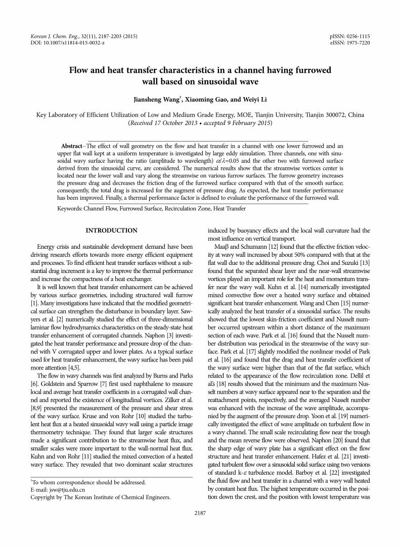
nel are steady. In this situation, the turbulence in the channel canbe considered to be fully developed turbulence. The computationaldomain is shown in Fig. 1(a), which has dimensions of 4λ×λ×2λin the streamwise, wall-normal and spanwise direction.
Computation has been performed for three cases with differentfurrowed bottom wall when Reb=(Ub·δ )/v=2800, where v denotesthe kinematic viscosity, δ represents the half-height of the channel,and Ub is the bulk velocity. The main geometry difference amongthe three cases is the shape of the lower wall. In case 1, the bottom isa conventional wavy wall characterized by the ratio of amplitude towavelength α/λ=0.05. The wavelength λ is equal to the channel heightH. The profile of the lower wall is represented by yw=αsin(2π x/λ),with the mean position located at y=0. The upper flat wall of thechannel is located at y=H. In case 2, the lower wall is formed bycutting the sinusoidal wavy wall of case 1 with a x-z plane at yh, whereyh is the distance from the plane at y=0 to the cutting x-z plane inthe wall-normal direction. We consider yh=α/2 in case 2 and yh=0in case 3. Three cases employed in present work are shown in Fig.1(b).
MATHEMATICAL FORMULATIONAND NUMERICAL METHOD
1. Governing EquationsWe assumed the flow to be unsteady, three-dimensional, incom-
pressible turbulent. The equations describing turbulent flow andheat transfer are given by the conservation of mass, momentumand energy. In large eddy simulation, filtered forms of the continuityand momentum equations for incompressible fluid are expressedas follows:
Fig. 1. Schematic diagram of the physical model: (a) Computationaldomain, (b) present three cases.
Flow and heat transfer characteristics in a channel having furrowed wall based on sinusoidal wave 2189
Korean J. Chem. Eng.(Vol. 32, No. 11)
(1)
(2)
where and are filtered velocity, filtered pressure and sub-grid-scale stress tensor, respectively, the indices i, j refer to the direc-tions of coordinates. The subgrid-scale stress tensor is defined as
= − .The large eddy simulations are performed by using the Smago-
rinsky-Lilly model [25] for the subgrid scales,
(3)
The eddy viscosity is defined as
(4)
where Cs is Smagorinsky coefficient, and Δ denotes the length scaleof the unresolved motion obtained from the volume of the com-putational cell ΔV,
(5)
and is the magnitude of the strain rate given in the followingequation:
(6)
(7)
The filtered form of the energy equation used in the presentstudy is expressed as follows:
(8)
where is filtered temperature and is the subgrid-scale heat fluxdefined as
(9)
2. Numerical DetailsNormalized temperature θ=(Tw−T)/(Tw−Tin), where Tin denotes
the inlet temperature of fluid, while Tw is the wall temperature. ThePrandtl number is set as Pr=0.71 with the reference of work byKadar [27]. Meantime, the Prandtl number of air is near 0.71. So,Pr=0.71 has more practical significance for engineering applica-tion. Where Pr=υ/a, υ (m2/s) and a (m2/s) is the kinematic viscos-ity and thermal diffusivity of fluid, respectively. No-slip conditionsare applied to both the upper and lower wall, and spatially peri-odic boundary conditions are assigned in the spanwise and stream-wise directions. The upper and the lower wall are kept at a uniformtemperature. All above-mentioned equations accompanied by bound-ary conditions are solved using finite volume method. The well-known SIMPLE algorithm [28] is used in the numerical process.The convective and diffusive terms of the discretized equations areapproximated by a second-order central difference scheme. The
Crank-Nicholson scheme is applied for the discretization of thetime term. The value of the time and space interval is selected toensure that the value of CFL<0.5. The CFL is defined as CFL=uΔτ/Δx, and Δx are time and space interval, respectively. The highervalue of CFL means that the convergence in numerical simulationproceeds faster and the stability becomes worse. In physics, the CFLmeans the ratio of -marching time in numerical simulation pro-cess to the time of the mechanical disturbance propagation. Thesimplest to understand is: the time-marching speed must be fasterthan the spread speed of physical disturbance.
To ensure the accuracy of the numerical results, a check for thegrid independence of the numerical solutions is conducted by sixdifferent grids for the flat channel. The grid size in the streamwise,spanwise and wall-normal directions along with the obtained Nus-selt number Nu=hδ/k and skin friction coefficient Cf =2τw/ρUb
2
are shown in Table 1. Finer grid may give a more accurate solu-tion. However, the improvement of the accuracy of computationwill decrease gradually when the number of grid points increasesbeyond a certain level. As shown in Table 1, a difference in the ob-tained results is not evident when the node numbers are more than1651200. Compared with the results of the finest computationaldomain grid, the relative deviation of the obtained Nusselt num-ber and friction factor of grid 160×129×80 is 0.19% and 0.12%,respectively. To lower computational costs, 160×129×80 is selectedas the final grid in the later numerical simulation. Since the fur-row surface geometry is easy to represent, hexagonal control vol-umes are employed. The grid is equidistant in the streamwise andspanwise directions. The grid near the wall in normal is refinedusing the bell shaped scheme considering the high gradient of theparameters. The bell shaped scheme means that the distribution ofgrid interval in normal obeys the bell shape function (Δy=e−y2, andy=0 is located at the normal center of the channel). In this scheme,the grid interval increases with the augment of normal distance tothe wall. The grid near the wall is dense and becomes sparse withthe increase of the normal distance to the wall. The y+ values ofthe first layer grid are less than 0.4; therefore, the boundary layerscan be fully resolved. It means that the parameters variation suchas temperature and velocity in the high gradient boundary layercan be captured.
RESULTS AND DISCUSSION
1. Validation of the Present LESThe simulation of the turbulent flow and heat transfer in a plane
channel is essential to check the accuracy of our approach in per-
∂ui
∂xi------- = 0
∂ui
∂t------- +
∂ uiuj( )∂xj
---------------- = − 1ρ---
∂p∂xi------- + v
∂2ui
∂xj∂xj-------------- −
∂τij
∂xj-------
ui, p τij
τij uiuj uiuj
τij − 13--τkkδij = − 2μtSij
μt = CsΔ( )2 S
Δ = ΔV( )1/3
S
S = 2SijSij
Sij = 12--
∂ui
∂xj------- +
∂uj
∂xi-------
⎝ ⎠⎛ ⎞
∂T∂t------ + uj
∂T∂xj------- =
vPr-----
∂2T∂xj∂xj-------------- −
∂hj
∂xj-------
T hj
hj = ujT − ujT
Table 1. Grid independence study at Re=2800Grid sizes (nodes) Nusselt number Nu Friction factor Cf
(80×65×40) 00208000 8.217 0.00755(120×65×60) 0468000 8.621 0.00791(120×110×60) 792000 8.811 0.00807(140×110×80) 1232000 8.981 0.00820(160×129×80) 1651200 9.064 0.00827(180×129×90) 2089800 9.081 0.00828
2190 J. Wang et al.
November, 2015
forming the LES at a bulk Reynolds number Reb=2800, which isequivalent to Re
τ=u
τδ/v=180. The dimension and grid numbers
in the streamwise, wall-normal and spanwise direction of the com-putational domain are the same as the furrow channel. The frictionvelocity u
τ is defined as u
τ= Fig. 2 shows the distribution of
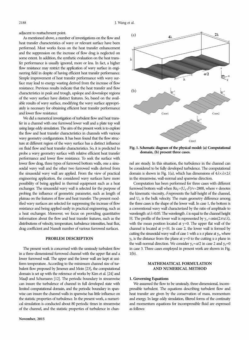
mean velocity and temperature, where y+=yuτ/v. The mean veloc-
ity profile, u+=u/uτ, as illustrated in Fig. 2(a), is compared with the
law of the wall u+=2.5lny++5.5, and the profile obtained from theDNS result by Kim et al. [24]. It shows excellent matching betweenthe profiles. In Fig. 2(b), the mean temperature profile is dividedby the average friction temperature, where T+= /T
τ, is the
temperature difference between the wall and the fluid. The frictiontemperature T
τ=qw/(ρcpuτ
). The absolute value of the temperaturedifference between the wall and the fluid is compared with the Kaderlog-law obtained from experiment for Pr=0.71, and has the formof T+=3.83+2.12lny+ [27]. As shown in figure, present results showgood agreement with the empirical law.
Other mean properties such as the skin friction coefficient andbulk mean velocity are also compared with the experimental cor-relations proposed by Dean [29]. In our study, the bulk Reynoldsnumber based on the full channel height is Reb=5600. The skinfriction coefficient Cf is 8.27×10⁻³, which is in good agreementwith the result obtained from Dean’s suggested correlation of Cf=0.073Reb
−0.25=8.44×10⁻³. The ratio of the mean centerline velocity
to the mean bulk velocity, Uc/Ub is 1.16, which shows an excellentagreement with the result obtained from Dean’s correlation of Uc/Ub=1.28Reb
−0.0116=1.16. The obtained Nusselt number is 9.064, whichis in good agreement with the result obtained from Gnielinski’s sug-gested correlation [30] ((f/8)(Re−1000)Pr)/(1+12.7(f/8)1/2(Pr2/3−1))=9.289, where f=(0.79lnRe−1.64)−2 is the friction factor.
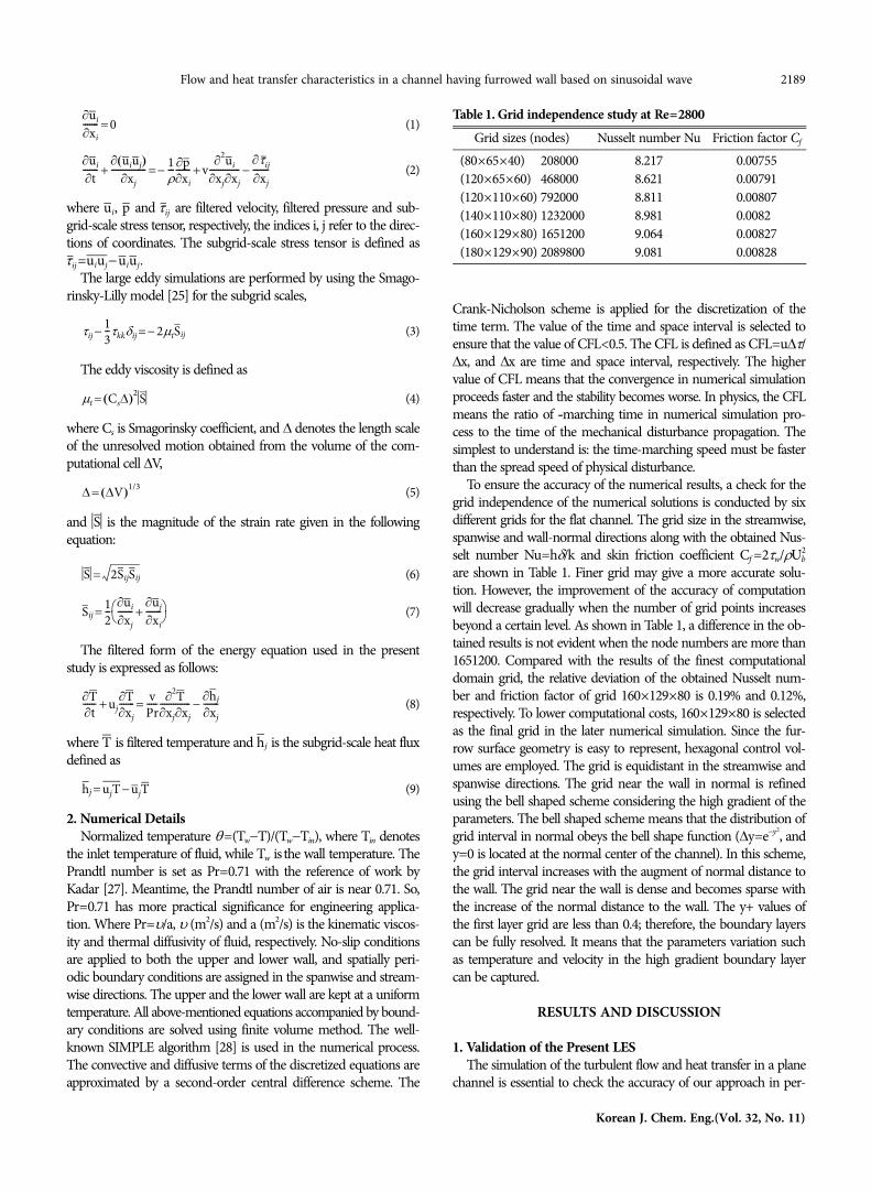
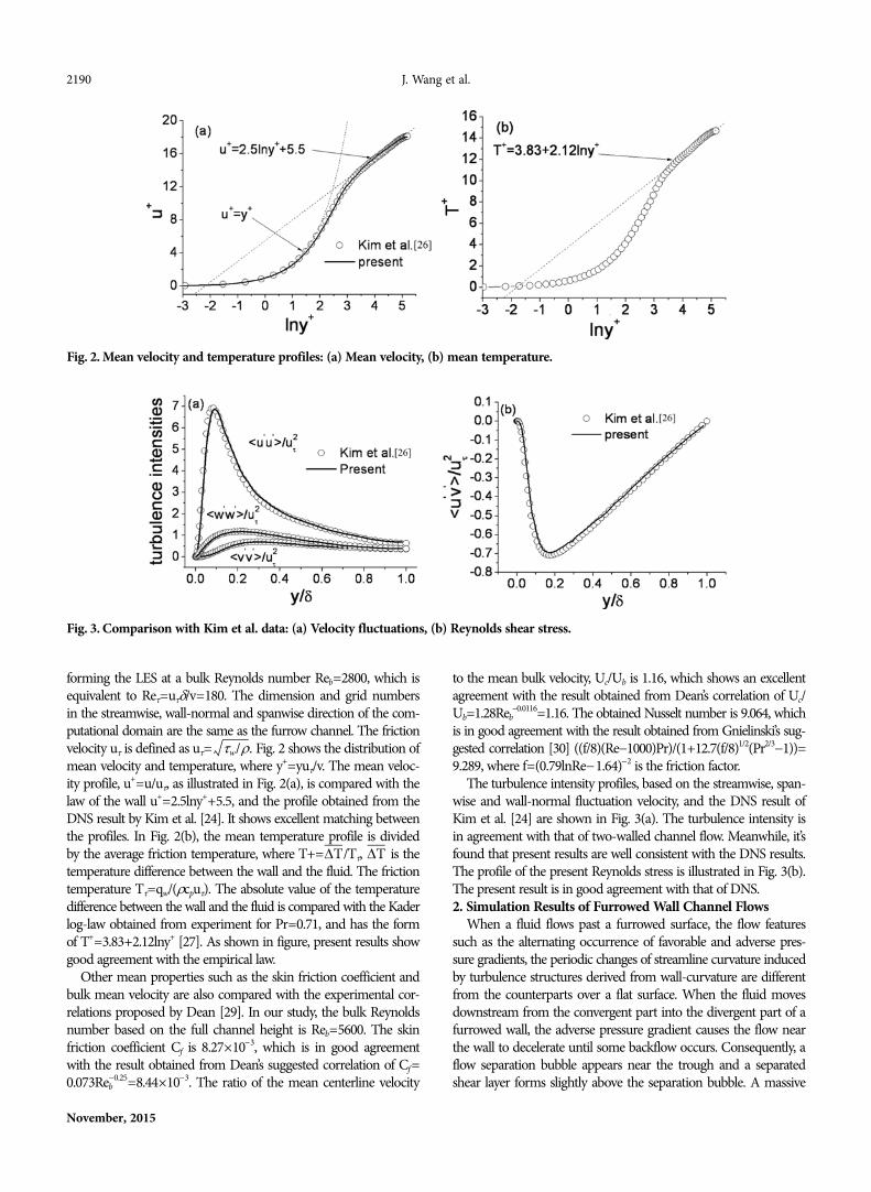
The turbulence intensity profiles, based on the streamwise, span-wise and wall-normal fluctuation velocity, and the DNS result ofKim et al. [24] are shown in Fig. 3(a). The turbulence intensity isin agreement with that of two-walled channel flow. Meanwhile, it’sfound that present results are well consistent with the DNS results.The profile of the present Reynolds stress is illustrated in Fig. 3(b).The present result is in good agreement with that of DNS.2. Simulation Results of Furrowed Wall Channel Flows
When a fluid flows past a furrowed surface, the flow featuressuch as the alternating occurrence of favorable and adverse pres-sure gradients, the periodic changes of streamline curvature inducedby turbulence structures derived from wall-curvature are differentfrom the counterparts over a flat surface. When the fluid movesdownstream from the convergent part into the divergent part of afurrowed wall, the adverse pressure gradient causes the flow nearthe wall to decelerate until some backflow occurs. Consequently, aflow separation bubble appears near the trough and a separatedshear layer forms slightly above the separation bubble. A massive
τw/ρ.
ΔT ΔT
Fig. 2. Mean velocity and temperature profiles: (a) Mean velocity, (b) mean temperature.
Fig. 3. Comparison with Kim et al. data: (a) Velocity fluctuations, (b) Reynolds shear stress.
Flow and heat transfer characteristics in a channel having furrowed wall based on sinusoidal wave 2191
Korean J. Chem. Eng.(Vol. 32, No. 11)
reversed flow accompanied with some high momentum fluid ele-ments locally penetrate into the separated zone, which promotesthe macroscopic mixings between the near-wall and core regionfluids. The heat transfer characteristics of flow through such fur-rowed channels are much more complex than that through paral-lel plate channels. The boundary layer formed on a furrowed wallis periodically destabilized by flow recirculation, successive acceler-ation and deceleration associated with multiple flow separationsand reattachments which replenish the near-wall fluids with thecore region fluids, which results in the augmenting of heat transfer.2-1. Global Flow and Heat Transfer Characteristics
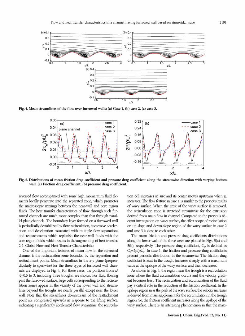
One of the important features of mean flow in the furrowedchannel is the recirculation zone bounded by the separation andreattachment points. Mean streamlines in the x-y plane (perpen-dicularly to spanwise) for the three types of furrowed wall chan-nels are displayed in Fig. 4. For these cases, the portions from x/λ=0.5 to 3, including three troughs, are shown. For fluid flowingpast the furrowed surface, large cells corresponding to the recircu-lation zones appear in the vicinity of the lower wall and stream-lines beyond the troughs are nearly parallel except near the lowerwall. Note that the streamlines downstream of the reattachmentpoint are compressed upwards in response to the lifting surface,indicating a significantly accelerated flow. Meantime, the recircula-
tion cell increases in size and its center moves upstream when yh
increases. The flow feature in case 1 is similar to the previous resultsof wavy surface. When the crest of the wavy surface is removed,the recirculation zone is stretched streamwise for the extrusionderived from main flow in channel. Compared to the previous rel-evant investigation on wavy surface, the effect scope of recirculationon up-slope and down-slope region of the wavy surface in case 2and case 3 is close to each other.
The mean friction and pressure drag coefficients distributionsalong the lower wall of the three cases are plotted in Figs. 5(a) and5(b), respectively. The pressure drag coefficient, Cp, is defined asCp=2p/ρUb
2. In case 1, the friction and pressure drag coefficientspresent periodic distribution in the streamwise. The friction dragcoefficient is least in the trough, increases sharply with a maximumvalue at the upslope of the wavy surface, and then decreases.
As shown in Fig. 4, the region near the trough is a recirculationzone where the fluid accumulation occurs and the velocity gradi-ent becomes least. The recirculation and accumulation of the fluidpay a critical role in the reduction of the friction coefficient. In theupslope region near the peak of the wavy surface, the velocity increasesis derived from mass supplement for the accumulation in the troughregion. So, the friction coefficient increases along the upslope of thewavy surface. There is an interesting phenomenon in that the maxi-
Fig. 4. Mean streamlines of the flow over furrowed walls: (a) Case 1, (b) case 2, (c) case 3.
Fig. 5. Distributions of mean friction drag coefficient and pressure drag coefficient along the streamwise direction with varying bottomwall: (a) Friction drag coefficient, (b) pressure drag coefficient.

2192 J. Wang et al.
November, 2015
mum friction coefficient does not occur at the peak of the wavysurface. The reason is that the velocity near the peak begins to reducegradually for the effect of the next recirculation and accumulationin downstream. In downslope region, the fluid velocity becomeslow for the existence of the recirculation zone. Consequently, thefriction coefficient at downslope region reduces gradually. It is obvi-ous that the recirculation caused by wavy surface leads the varia-tion of the friction coefficient.
The variation of friction drag coefficient reflects the alternatingappearance of the favorable and adverse pressure gradients or theappearance of flow separations and reattachments induced by thefurrows. The pressure drag coefficient also shows an undulatedfeature with an increase on the upslope side and becomes least nearthe crest point. Note that the reverse flow causes the distributionof the friction and pressure drag coefficients to deviate from thesinusoidal pattern of the wavy surface in the trough. In cases 2 and3, the distributions of friction and pressure drag coefficient are sim-ilar to that in case 1. The main difference is on the plateau por-tions where corresponding to the crest in case 1. The friction dragcoefficient reaches a peak at the front edge of the plateau and then
Fig. 6. Locations of separation and reattachment points for threecases.
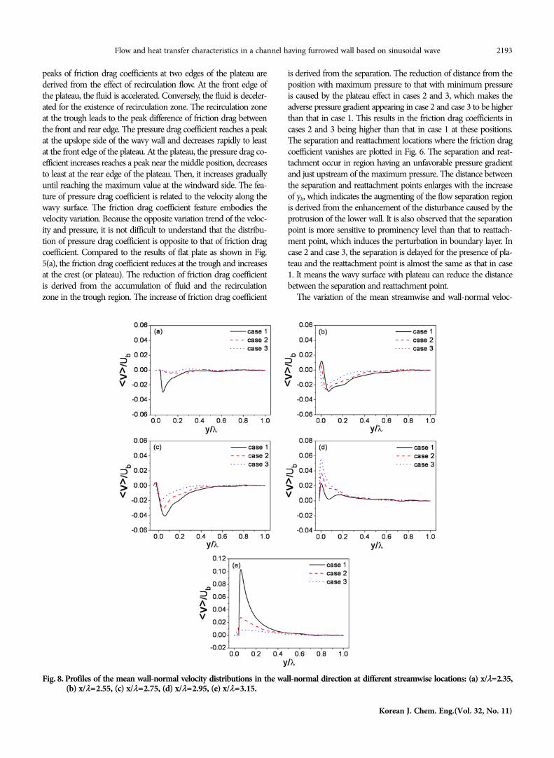
Fig. 7. Profiles of the mean streamwise velocity distributions in the wall-normal direction at different streamwise locations: (a) x/λ=2.35, (b)x/λ=2.55, (c) x/λ=2.75, (d) x/λ=2.95, (e) x/λ=3.15.
drops sharply. Then, the friction drag coefficient increases gener-ally and reaches a peak again at the rear edge of the plateau. The
Flow and heat transfer characteristics in a channel having furrowed wall based on sinusoidal wave 2193
Korean J. Chem. Eng.(Vol. 32, No. 11)
peaks of friction drag coefficients at two edges of the plateau arederived from the effect of recirculation flow. At the front edge ofthe plateau, the fluid is accelerated. Conversely, the fluid is deceler-ated for the existence of recirculation zone. The recirculation zoneat the trough leads to the peak difference of friction drag betweenthe front and rear edge. The pressure drag coefficient reaches a peakat the upslope side of the wavy wall and decreases rapidly to leastat the front edge of the plateau. At the plateau, the pressure drag co-efficient increases reaches a peak near the middle position, decreasesto least at the rear edge of the plateau. Then, it increases graduallyuntil reaching the maximum value at the windward side. The fea-ture of pressure drag coefficient is related to the velocity along thewavy surface. The friction drag coefficient feature embodies thevelocity variation. Because the opposite variation trend of the veloc-ity and pressure, it is not difficult to understand that the distribu-tion of pressure drag coefficient is opposite to that of friction dragcoefficient. Compared to the results of flat plate as shown in Fig.5(a), the friction drag coefficient reduces at the trough and increasesat the crest (or plateau). The reduction of friction drag coefficientis derived from the accumulation of fluid and the recirculationzone in the trough region. The increase of friction drag coefficient
is derived from the separation. The reduction of distance from theposition with maximum pressure to that with minimum pressureis caused by the plateau effect in cases 2 and 3, which makes theadverse pressure gradient appearing in case 2 and case 3 to be higherthan that in case 1. This results in the friction drag coefficients incases 2 and 3 being higher than that in case 1 at these positions.The separation and reattachment locations where the friction dragcoefficient vanishes are plotted in Fig. 6. The separation and reat-tachment occur in region having an unfavorable pressure gradientand just upstream of the maximum pressure. The distance betweenthe separation and reattachment points enlarges with the increaseof yh, which indicates the augmenting of the flow separation regionis derived from the enhancement of the disturbance caused by theprotrusion of the lower wall. It is also observed that the separationpoint is more sensitive to prominency level than that to reattach-ment point, which induces the perturbation in boundary layer. Incase 2 and case 3, the separation is delayed for the presence of pla-teau and the reattachment point is almost the same as that in case1. It means the wavy surface with plateau can reduce the distancebetween the separation and reattachment point.
The variation of the mean streamwise and wall-normal veloc-
Fig. 8. Profiles of the mean wall-normal velocity distributions in the wall-normal direction at different streamwise locations: (a) x/λ=2.35,(b) x/λ=2.55, (c) x/λ=2.75, (d) x/λ=2.95, (e) x/λ=3.15.
2194 J. Wang et al.
November, 2015
ity along the streamwise plays a vital role in fluid structure nearthe wall. Fig. 7 and Fig. 8 show the distributions of the streamwiseand wall-normal mean velocity, which are obtained at five charac-teristic streamwise positions (x/λ=2.35, 2.55, 2.75, 2.95, 3.15). Incase 1, point a (x/λ=2.35) is located near the crest of the wavy walland the front of separation point. Points b and c (x/λ=2.55, 2.75,respectively) are located in recirculation region. Points d and e (x/λ=2.95, 3.15, respectively) are located in the rear of reattachmentpoint. Due to the drag at the lower wall is larger than that at theupper flat wall, the streamwise velocity peak is shifted towards theflat top wall and shows the asymmetry. The wall-normal velocityin all cases presents negative values in the separation region, whichis derived from the downward motion. The positive values in ups-lope region close to the lower wall are caused by recirculation.
At x/λ=2.35 just the front of recirculation zone, the mean stream-wise velocity, presents positive even near the lower surface as thatin flat channel flow, and grows quickly in a short distance. In cases2 and 3, the wall-normal velocity tends to zero for being located atthe plateau and the motion in normal is bounded by the wall. Thenegative mean wall-normal velocity appears in case 1 for being locatedat the downslope of the wall.
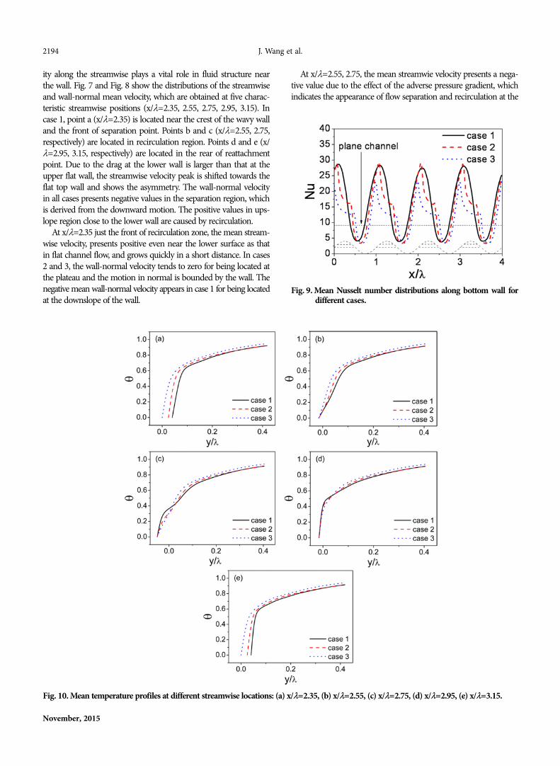
Fig. 9. Mean Nusselt number distributions along bottom wall fordifferent cases.
Fig. 10. Mean temperature profiles at different streamwise locations: (a) x/λ=2.35, (b) x/λ=2.55, (c) x/λ=2.75, (d) x/λ=2.95, (e) x/λ=3.15.
At x/λ=2.55, 2.75, the mean streamwie velocity presents a nega-tive value due to the effect of the adverse pressure gradient, whichindicates the appearance of flow separation and recirculation at the
Flow and heat transfer characteristics in a channel having furrowed wall based on sinusoidal wave 2195
Korean J. Chem. Eng.(Vol. 32, No. 11)
downslope side of the wall. The magnitude of velocity in case 1 islarger than that in cases 2 and 3, implying stronger reversed flowoccurs. The wall-normal velocity near the lower wall presents thepositive values as shown in Figs. 8(b) and Fig. 8(c), which resultsin the fluid eingb pushed upward along the lower surface by thereversed flow. The magnitude of wall-normal velocity in case 1 islarger than that in cases 2 and 3 for core fluids deep swarm intothe trough, which is induced by a stronger reversed flow.
At x/λ=2.95, 3.15 downstream of the reattachment point, thenear-wall flow is accelerated by a favorable pressure gradient. Thenegative streamwise and wall-normal velocity disappear as shownin Figs. 7(d), 7(e), 8(d) and 8(e). At x/λ=2.95, the streamwise veloc-ity gradients in the region close to the walls in cases 2 and 3 arehigher than that in case 1. The wall-normal velocity in cases 2 and3 is larger than that in case 1 on account of the existence of the farupstream reattachment points in cases 2 and 3. At x/λ=3.15, thestreamwise velocity gradient in the region close to the wall in case1 is obviously larger than that in cases 2 and 3, and the wall-nor-mal velocity is larger than that in cases 2 and 3. Above-mentionedflow features indicate that the accelerated region downstream the
reattachment point reduces as yh decreases. Compared with theprevious work on wavy surface, it’s found that the wall-normal veloc-ity can be affected by the presence of plateau, which has obviousinfluence on flow and heat transfer characteristics.
As fluid flows over the furrowed heated walls, the breaking anddestabilizing thermal boundary layer are promoted by the onsetand growth of recirculation zones, resulting in enhancing heat trans-fer. Fig. 9 shows the variation of the Nusselt number along the lowerwall of the channel in three cases. By the way, the smooth parallel-plates case is also plotted for reference purposes as shown in thedash dot black line. Due to the effect of recirculation, at the upstreamseparation point, hot fluid is pushed away from the heated upperwall, creating a lower heat flux. The cool fluid near the downstreamreattachment point is pushed toward the wall, forming a higherheat flux. As a result, the local Nusselt number increases in the con-verging section and decreases in diverging section accompanied bythe minimum and the maximum values near the separation andthe reattachment points, respectively. The local Nusselt numbersalong the lower wall are larger than that of the plate wall exceptthat at the downslope side of the furrow wall. The minimum Nus-
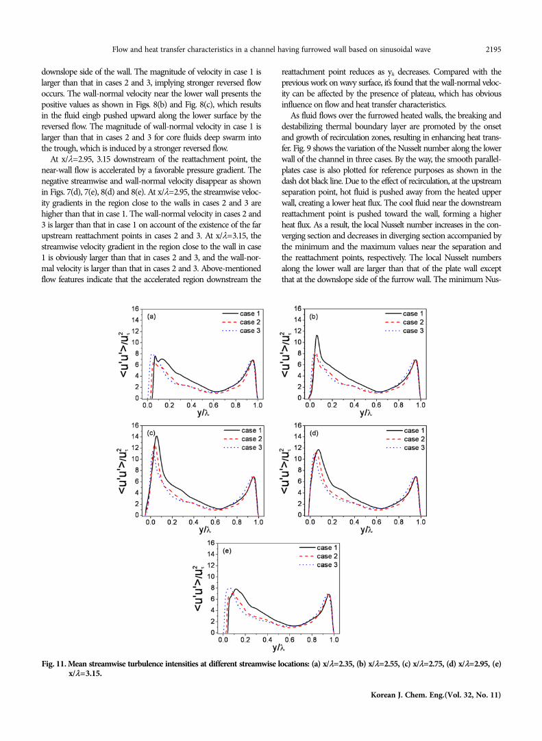
Fig. 11. Mean streamwise turbulence intensities at different streamwise locations: (a) x/λ=2.35, (b) x/λ=2.55, (c) x/λ=2.75, (d) x/λ=2.95, (e)x/λ=3.15.
2196 J. Wang et al.
November, 2015
selt numbers near the separation points in cases 2 and 3 are smallerthan that in case 1 as a result of weaker reversed flow.
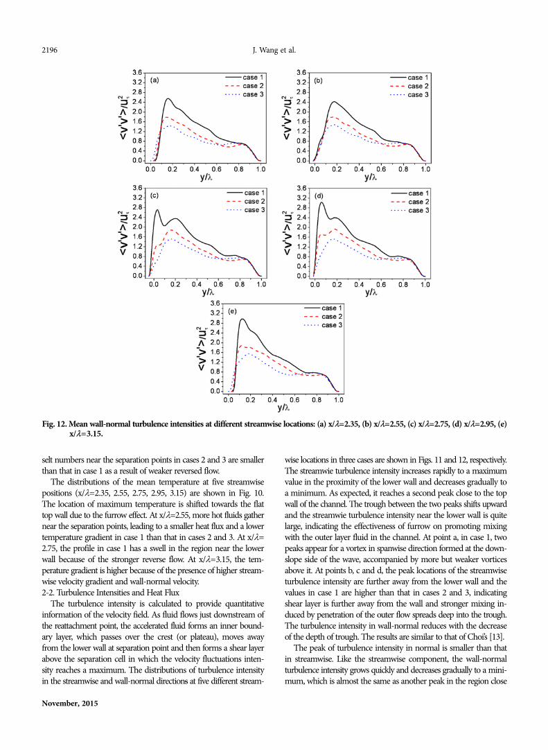
The distributions of the mean temperature at five streamwisepositions (x/λ=2.35, 2.55, 2.75, 2.95, 3.15) are shown in Fig. 10.The location of maximum temperature is shifted towards the flattop wall due to the furrow effect. At x/λ=2.55, more hot fluids gathernear the separation points, leading to a smaller heat flux and a lowertemperature gradient in case 1 than that in cases 2 and 3. At x/λ=2.75, the profile in case 1 has a swell in the region near the lowerwall because of the stronger reverse flow. At x/λ=3.15, the tem-perature gradient is higher because of the presence of higher stream-wise velocity gradient and wall-normal velocity.2-2. Turbulence Intensities and Heat Flux
The turbulence intensity is calculated to provide quantitativeinformation of the velocity field. As fluid flows just downstream ofthe reattachment point, the accelerated fluid forms an inner bound-ary layer, which passes over the crest (or plateau), moves awayfrom the lower wall at separation point and then forms a shear layerabove the separation cell in which the velocity fluctuations inten-sity reaches a maximum. The distributions of turbulence intensityin the streamwise and wall-normal directions at five different stream-
wise locations in three cases are shown in Figs. 11 and 12, respectively.The streamwie turbulence intensity increases rapidly to a maximumvalue in the proximity of the lower wall and decreases gradually toa minimum. As expected, it reaches a second peak close to the topwall of the channel. The trough between the two peaks shifts upwardand the streamwie turbulence intensity near the lower wall is quitelarge, indicating the effectiveness of furrow on promoting mixingwith the outer layer fluid in the channel. At point a, in case 1, twopeaks appear for a vortex in spanwise direction formed at the down-slope side of the wave, accompanied by more but weaker vorticesabove it. At points b, c and d, the peak locations of the streamwiseturbulence intensity are further away from the lower wall and thevalues in case 1 are higher than that in cases 2 and 3, indicatingshear layer is further away from the wall and stronger mixing in-duced by penetration of the outer flow spreads deep into the trough.The turbulence intensity in wall-normal reduces with the decreaseof the depth of trough. The results are similar to that of Choi’s [13].
The peak of turbulence intensity in normal is smaller than thatin streamwise. Like the streamwise component, the wall-normalturbulence intensity grows quickly and decreases gradually to a mini-mum, which is almost the same as another peak in the region close
Fig. 12. Mean wall-normal turbulence intensities at different streamwise locations: (a) x/λ=2.35, (b) x/λ=2.55, (c) x/λ=2.75, (d) x/λ=2.95, (e)x/λ=3.15.
Flow and heat transfer characteristics in a channel having furrowed wall based on sinusoidal wave 2197
Korean J. Chem. Eng.(Vol. 32, No. 11)
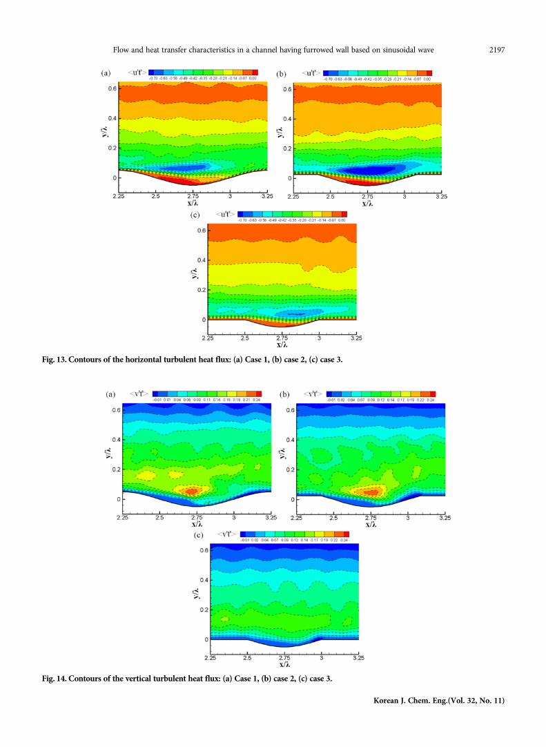
Fig. 13. Contours of the horizontal turbulent heat flux: (a) Case 1, (b) case 2, (c) case 3.
Fig. 14. Contours of the vertical turbulent heat flux: (a) Case 1, (b) case 2, (c) case 3.
2198 J. Wang et al.
November, 2015
to the top wall as shown in Fig. 12, indicating a larger effect of thewall furrow on the vertical fluctuations than it does on the stream-wise component. The peaks at points c, d and e are larger than thatat points a and b because of the stronger penetration of the coreflow at point c and local flow acceleration at points d and e. Themagnitude of the wall-normal turbulence intensity increases withthe augment of yh because it is so sensitive to the roughness. It isworth noting that two peak values are located at y/λ=0.0345 andy/λ=0.2, respectively, at point c, in case 1. The first peak is locatedclose to the wall due to the stronger penetration of outer fluids,and the second peak appears far away from the lower wall becauseof the separated shear layer above separation bubble.
Contours of the horizontal and vertical turbulent heat flux com-ponents in the x-y plane with the portions from x/λ=2.25 to 3.25are shown in Figs. 13 and 14. The heat flux can be defined as theenergy in transit due to a temperature difference. The highest tur-bulent flux is concentrated in the region above the recirculationzones because the separated shear layer in the proximity of the sepa-ration region is the locus of large turbulence intensity and the mix-ing of cool and hot fluids. In case 3, the value of the heat flux nearthe lower wall is smaller than that in cases 1 and 2, and there is noan obvious highest wall-normal turbulent heat flux value regionfor weak recirculation. The highest value region of streamwise heatflux moves downward the furrow with the reduction of the recir-culation zone size in the cases. The interaction between the recir-culation zone and the shear layer principally influences the heatflux. The streamwise turbulent heat flux component above the recir-culation zone in case 2 is influenced by the strength of the recircu-lation flow, temperature and streamwise velocity gradients, which
is larger than that in case 1. Although recirculation is the stron-gest in case 1, the temperature and streamwise velocity gradientsabove the recirculation zone are small at points b, c and d as shownin Figs. 7 and 10. The intensity of the vertical turbulent heat fluxin case 1 is the highest because more smaller scale structures makea significant contribution to the vertical heat flux. The small scalestructure is generated on the downslope side of the furrowed wall,accompanied by stronger recirculation flow and the area with high-est vertical turbulent heat flux region is enlarged. Based on the resultsby Kruse et al. [10], it can be predicted that the small scale vorti-ces are contained in the recirculation motion. In other words, alarge scale recirculation structure consists of small scale vorticesstructure.2-3. Flow Structure and Thermal Performance
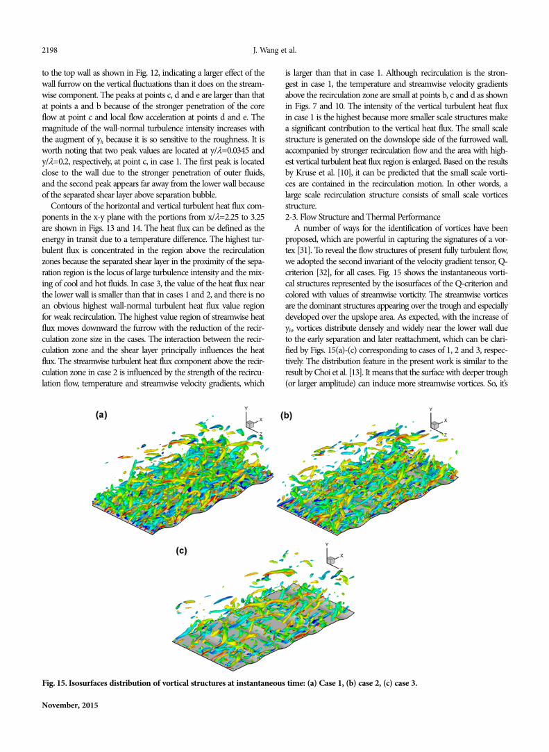
A number of ways for the identification of vortices have beenproposed, which are powerful in capturing the signatures of a vor-tex [31]. To reveal the flow structures of present fully turbulent flow,we adopted the second invariant of the velocity gradient tensor, Q-criterion [32], for all cases. Fig. 15 shows the instantaneous vorti-cal structures represented by the isosurfaces of the Q-criterion andcolored with values of streamwise vorticity. The streamwise vorticesare the dominant structures appearing over the trough and especiallydeveloped over the upslope area. As expected, with the increase ofyh, vortices distribute densely and widely near the lower wall dueto the early separation and later reattachment, which can be clari-fied by Figs. 15(a)-(c) corresponding to cases of 1, 2 and 3, respec-tively. The distribution feature in the present work is similar to theresult by Choi et al. [13]. It means that the surface with deeper trough(or larger amplitude) can induce more streamwise vortices. So, it’s
Fig. 15. Isosurfaces distribution of vortical structures at instantaneous time: (a) Case 1, (b) case 2, (c) case 3.

Flow and heat transfer characteristics in a channel having furrowed wall based on sinusoidal wave 2199
Korean J. Chem. Eng.(Vol. 32, No. 11)
not difficult to understand the surface with larger amplitude canbring better heat transfer performance.
It can be found that the drastically decreased number of vorti-ces occurs in case 3, and the numbers of the vortices in cases 1 and2 have no obvious difference. It indicates that the vortices can beinduced by wavy wall and the plateau at the wavy wall can weakenthe vortices.
The root mean square vorticity fluctuations normalized by themean shear are presented in Fig. 16. The streamwise vorticity fluc-tuations decrease rapidly in the vicinity of the lower wall and in-crease gradually to a maximum, and then decrease again. As ex-pected, the profiles have similar shape, which have a peak in theregion close to the upper wall of the channel and show asymme-try due to the furrow effect on the lower wall. The magnitudes ofthe streamwise vorticity fluctuations in the upslope region are higherthan that in the downslope region, which is derived from the vor-tex stretching, accompanied with the near-wall flow accelerationin the upslope region. The interesting fact is the variation of thepeak of the streamwise vorticity fluctuations. The location of thelocal maximum corresponds to the location of the average stream-wise vorticity center. The locations of the streamwise vorticity fluc-
tuations peaks at different streamwise locations are plotted in Fig.17. It can be found that the locations profile of the average stream-wise vorticity center has a similar shape to that of the lower wall.In cases 2 and 3, the profiles shift upward at x/λ=2.55 due to nor-mal velocity caused by the recirculation flow near the separationpoint, having influence on the sweep motion in front of the sepa-ration point. While it does not occurs in case 1 due to powerfulsweep motion induced by the increase of the distance from the wavepeak to the separation point. Fig. 17(b) presents the distance (d/λ)from the streamwise vorticiy fluctuations peak to the lower wall inall cases. At the plateaus, the streamwise vortices are far away fromthe wall in case 3. In the trough, the distance in case 2 is larger thanthat in cases 1 and 3, which has minimum values in case 1. It indi-cates that the streamwise vortices are far away from the wall in case2 and spread deep into the trough in case 1. It indicates that thestreamwise vortices are bounded in the trough. In the trough, theinflexion points of three cases are shown in Fig. 17(a). Because thestreamwise vortices are lifted by the wall curvature when they flowtowards the wall, fluid flows toward the wall at a further upstreamin case 1 than it does in cases 2 and 3 as a result of stronger recir-culation flow in case 1. It also leads to the position distribution of
Fig. 16. Streamwise vorticity fluctuations at different streamwise locations: (a) x/λ=2.35, (b) x/λ=2.55, (c) x/λ=2.75, (d) x/λ=2.95, (e) x/λ=3.15.
2200 J. Wang et al.
November, 2015
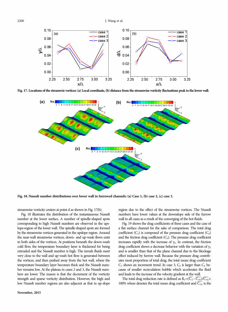
streamwise vorticity centers at point d as shown in Fig. 17(b).Fig. 18 illustrates the distribution of the instantaneous Nusselt
number at the lower surface. A number of spindle-shaped spotscorresponding to high Nusselt numbers are observed in the ups-lope-region of the lower wall. The spindle-shaped spots are formedby the streamwise vortices generated in the upslope region. Aroundthe near-wall streamwise vortices, down- and up-wash flows existin both sides of the vortices. At positions beneath the down-washcold flow, the temperature boundary layer is thickened for beingextruded and the Nusselt number is high. The inrush fluids meetvery close to the wall and up-wash hot flow is generated betweenthe vortices, and then pushed away from the hot wall, where thetemperature boundary layer becomes thick and the Nusselt num-ber remains low. At the plateau in cases 2 and 3, the Nusselt num-bers are lower. The reason is that the decrement of the vorticitystrength and sparse vorticity distribution. However, the high andlow Nusselt number regions are also adjacent as that in up-slope
region due to the effect of the streamwise vortices. The Nusseltnumbers have lower values at the downslope side of the furrowwall in all cases as a result of the converging of the hot fluids.
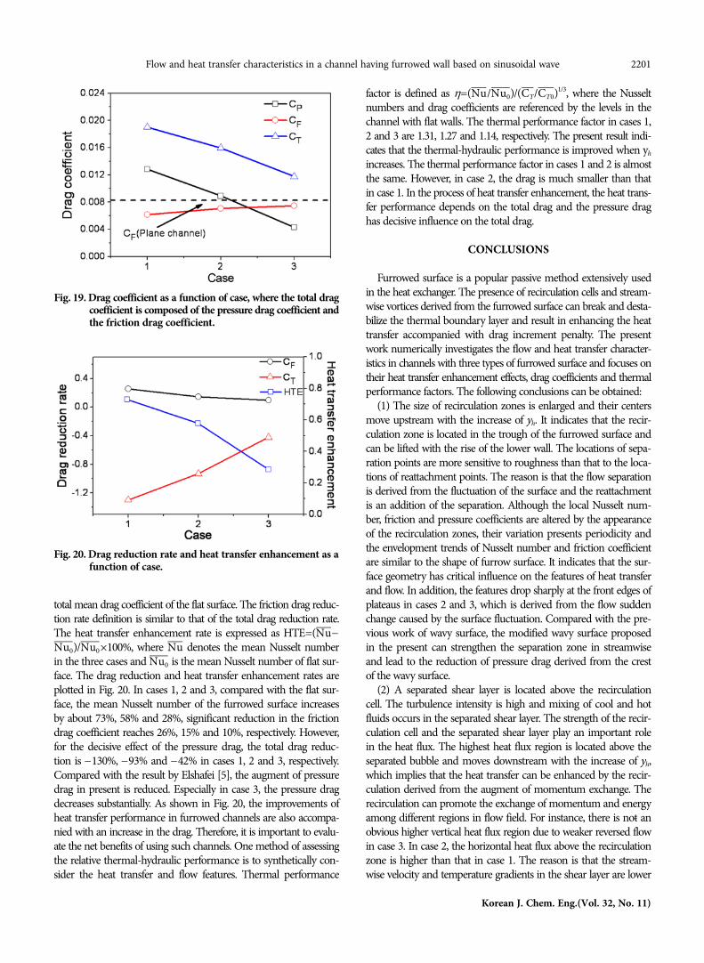
Fig. 19 shows the drag coefficients of three cases and the case ofa flat surface channel for the sake of comparison. The total dragcoefficient (CT) is composed of the pressure drag coefficient (CP)and the friction drag coefficient (CF). The pressure drag coefficientincreases rapidly with the increase of yh. In contrast, the frictiondrag coefficient shows a decrease behavior with the variation of yh
and is smaller than that of the plane channel due to the blockageeffect induced by furrow wall. Because the pressure drag contrib-utes most proportion of total drag, the total mean drag coefficientCT shows an increment trend. In case 3, CF is larger than CP be-cause of smaller recirculation bubble which accelerates the fluidand leads to the increase of the velocity gradient at the wall.
The total drag reduction rate is defined as RT=( − )/ ×100% where denotes the total mean drag coefficient and is the
CT CT0 CT0
CT0
Fig. 17. Locations of the streamwie vortices: (a) Local coordinate, (b) distance from the streamwise vortictiy fluctuations peak to the lower wall.
Fig. 18. Nusselt number distributions over lower wall in furrowed channels: (a) Case 1, (b) case 2, (c) case 3.
Flow and heat transfer characteristics in a channel having furrowed wall based on sinusoidal wave 2201
Korean J. Chem. Eng.(Vol. 32, No. 11)
total mean drag coefficient of the flat surface. The friction drag reduc-tion rate definition is similar to that of the total drag reduction rate.The heat transfer enhancement rate is expressed as HTE=( −
)/ ×100%, where denotes the mean Nusselt numberin the three cases and is the mean Nusselt number of flat sur-face. The drag reduction and heat transfer enhancement rates areplotted in Fig. 20. In cases 1, 2 and 3, compared with the flat sur-face, the mean Nusselt number of the furrowed surface increasesby about 73%, 58% and 28%, significant reduction in the frictiondrag coefficient reaches 26%, 15% and 10%, respectively. However,for the decisive effect of the pressure drag, the total drag reduc-tion is −130%, −93% and −42% in cases 1, 2 and 3, respectively.Compared with the result by Elshafei [5], the augment of pressuredrag in present is reduced. Especially in case 3, the pressure dragdecreases substantially. As shown in Fig. 20, the improvements ofheat transfer performance in furrowed channels are also accompa-nied with an increase in the drag. Therefore, it is important to evalu-ate the net benefits of using such channels. One method of assessingthe relative thermal-hydraulic performance is to synthetically con-sider the heat transfer and flow features. Thermal performance
factor is defined as η=( / )/( / )1/3, where the Nusseltnumbers and drag coefficients are referenced by the levels in thechannel with flat walls. The thermal performance factor in cases 1,2 and 3 are 1.31, 1.27 and 1.14, respectively. The present result indi-cates that the thermal-hydraulic performance is improved when yh
increases. The thermal performance factor in cases 1 and 2 is almostthe same. However, in case 2, the drag is much smaller than thatin case 1. In the process of heat transfer enhancement, the heat trans-fer performance depends on the total drag and the pressure draghas decisive influence on the total drag.
CONCLUSIONS
Furrowed surface is a popular passive method extensively usedin the heat exchanger. The presence of recirculation cells and stream-wise vortices derived from the furrowed surface can break and desta-bilize the thermal boundary layer and result in enhancing the heattransfer accompanied with drag increment penalty. The presentwork numerically investigates the flow and heat transfer character-istics in channels with three types of furrowed surface and focuses ontheir heat transfer enhancement effects, drag coefficients and thermalperformance factors. The following conclusions can be obtained:
(1) The size of recirculation zones is enlarged and their centersmove upstream with the increase of yh. It indicates that the recir-culation zone is located in the trough of the furrowed surface andcan be lifted with the rise of the lower wall. The locations of sepa-ration points are more sensitive to roughness than that to the loca-tions of reattachment points. The reason is that the flow separationis derived from the fluctuation of the surface and the reattachmentis an addition of the separation. Although the local Nusselt num-ber, friction and pressure coefficients are altered by the appearanceof the recirculation zones, their variation presents periodicity andthe envelopment trends of Nusselt number and friction coefficientare similar to the shape of furrow surface. It indicates that the sur-face geometry has critical influence on the features of heat transferand flow. In addition, the features drop sharply at the front edges ofplateaus in cases 2 and 3, which is derived from the flow suddenchange caused by the surface fluctuation. Compared with the pre-vious work of wavy surface, the modified wavy surface proposedin the present can strengthen the separation zone in streamwiseand lead to the reduction of pressure drag derived from the crestof the wavy surface.
(2) A separated shear layer is located above the recirculationcell. The turbulence intensity is high and mixing of cool and hotfluids occurs in the separated shear layer. The strength of the recir-culation cell and the separated shear layer play an important rolein the heat flux. The highest heat flux region is located above theseparated bubble and moves downstream with the increase of yh,which implies that the heat transfer can be enhanced by the recir-culation derived from the augment of momentum exchange. Therecirculation can promote the exchange of momentum and energyamong different regions in flow field. For instance, there is not anobvious higher vertical heat flux region due to weaker reversed flowin case 3. In case 2, the horizontal heat flux above the recirculationzone is higher than that in case 1. The reason is that the stream-wise velocity and temperature gradients in the shear layer are lower
NuNu0 Nu0 Nu
Nu0
Nu Nu0 CT CT0
Fig. 19. Drag coefficient as a function of case, where the total dragcoefficient is composed of the pressure drag coefficient andthe friction drag coefficient.
Fig. 20. Drag reduction rate and heat transfer enhancement as afunction of case.

2202 J. Wang et al.
November, 2015
although the reversed flow is the strongest in case 1.(3) The streamwise vortices are the dominant flow structures,
some of which formed in the rear of the crest (or plateau) and oth-ers generated with larger population in the upslope region. Thelocation of streamwise vorticity center in streamwise has a similarshape with the lower surface. However, the locations near the rearedge of the plateau in cases 2 and 3 are slightly lifted as a result ofthe normal velocity caused by the reversal flow and a shorter dis-tance from the rear edge to the separation point. It’s revealed thatthe reversal flow caused by circulation has an influence on the stream-wise vortices. In the trough, the streamwise vortices are furtheraway from the lower wall in case 2 and closest to the lower wall incase 1, inducing inrush of core fluids spreads deep into the troughin case 1. It’s found that the deeper trough can gather fluid and boundstreamwise vortices.
(4) For the furrow wall surface, the fact that improvement in heattransfer performance is accompanied with a drag increase penaltyhas been verified by many relevant investigations. The total dragcoefficient of the present furrow surface is higher than that of theflat wall due to the increase of the pressure drag coefficient. How-ever, the friction drag coefficient can be decreased owing to thepresence of the low speed fluid accumulation in trough of the fur-row surface. The fluid in trough region can suppresses the evolu-tion of streamwise vortices, which is beneficial for drag reduction.But the ledge of the furrow surface can strengthen the disturbancein flow field and lead to the increase of pressure and friction drag.The half-cutting furrowed surface (in case 2) has similar thermalperformance factor to sinusoidal wavy wall (in case 1), which is abetter choice for heat transfer enhancement when there are demandsof lower drag increment penalty. To obtain a better thermal per-formance factor, it is necessary to combine the trough and ledgeportion of the furrow surface properly. On the promise of achiev-ing heat transfer enhancement, keeping the total drag in a relativelow level is important for practical engineering application.
ACKNOWLEDGEMENT
The authors gratefully acknowledge the financial support by theNational Nature Science Fund of China (No.50476063).
NOMENCLATURE
Cf : skin friction coefficientCp : pressure coefficientcp : specific heat capacity at constant pressure [j·kg−1·K−1]Cs : Smagorinsky constantCT : total drag coefficientH : full channel height [m]h : heat transfer coefficient [w·m−2·k−1]
: subgrid scale heat fluxk : thermal conductivity of the fluid [w·m−1·k−1]Nu : Nusselt numberPr : Prandtl numberqw : wall heat flux [w·m−2]Reb : Reynolds number for channel half-heightRe
τ: Reynolds number based on friction velocity
Tin : inlet temperature [K]Tw : bottom wall temperature [K]Tτ
: friction temperatureT+ : dimensionless temperature normalized by friction tempera-
tureUb : bulk velocity [m·s−1]Uc : mean centerline velocity [m·s−1]uτ
: friction velocityu+ : dimensionless velocity normalized by friction velocityyh : the distance from the plane at y=0 to the cutting x-z plane
in the wall-normal direction [m]yw : profile of the wavy bottom wall [m]y+ : dimensionless length normalized by wall variablesα : wave amplitude [m]δ : channel half-height [m]Δ : characteristic grid spacingη : thermal performance factorθ : nondimensional temperatureλ : wave length [m]ν : kinematic viscosity [m2·s−1]ρ : fluid density [kg·m−3]
: subgrid turbulent stressτw : wall shear stressωx : streamwise vorticity
REFERENCES
1. C. Phan, D. L. Holgate and G. J. Griffin, Korean J. Chem. Eng., 20,1012 (2003).
2. D. R. Sawyers, M. Sen and H. C. Chang, Int. J. Heat Mass Trans-fer, 41, 3559 (1998).
3. P. Naphon, Energ. Convers. Manage., 48, 1516 (2007).4. S. W. Chang, A. W. Lees and T. C. Chou, Int. J. Heat Mass Trans-
fer, 52, 4592 (2009).5. E. A. M. Elshafei, M. M. Awad, E. El-Negiry and A. G. Ali, Energy,
35, 101 (2010).6. J. C. Burns and T. Parks, J. Fluid Mech., 29, 405 (1967).7. L. Goldstein and E. M. Sparrow, J. Heat Trans.-T. ASME, 99, 187
(1977).8. D. P. Zilker, G. W. Cook and T. J. Hanratty, J. Fluid Mech., 82, 29
(1977).9. D. P. Zilker and T. J. Hanratty, J. Fluid Mech., 90, 257 (1979).
10. N. Kruse and P. Rudolf von Rohr, Int. J. Heat Mass Transfer, 49,3514 (2006).
11. S. Kuhn and P. Rudolf von Rohr, Int. J. Heat Fluid Flow, 29, 94(2008).
12. C. Maaβ and U. Schumann, In: Hirschel, E. H. (Ed.), Flow simula-tion with high performance computers, Notes on Numerical FluidMechanics, 52, 227 (1996).
13. H. S. Choi and K. Suzuki, Int. J. Heat Fluid Flow, 26, 681 (2005).14. S. Kuhn, S. Kenjeres and P. Rudolf von Rohr, Int. J. Therm. Sci.,
49, 1209 (2010).15. C. C. Wang and C. K. Chen, Int. J. Heat Mass Transfer, 45, 2587
(2002).16. T. S. Park, H. J. Sung and K. Suzuki, Int. J. Heat Fluid Flow, 24, 29
(2003).
hj
τij
Flow and heat transfer characteristics in a channel having furrowed wall based on sinusoidal wave 2203
Korean J. Chem. Eng.(Vol. 32, No. 11)
17. T. S. Park, H. S. Choi and K. Suzuki, Int. J. Heat Mass Transfer, 47,2403 (2004).
18. A. Z. Dellil, A. Azzi and B. A. Jubran, Heat Mass Transfer, 40, 793(2004).
19. H. S. Yoon, O. A. El-Samni, A. T. Huynh, H. H. Chun, H. J. Kim,A. H. Pham and I. P. Park, Ocean Eng., 36, 697 (2009).
20. P. Naphon, Int. Commun. Heat Mass, 36, 942 (2009).21. K. A. Hafez, O. A. Elsamni and K. Y. Zakaria, Alex. Eng. J., 50, 145
(2011).22. S. Barboy, A. Rashkovan and G. Ziskind, Int. J. Heat Mass Trans-
fer, 55, 3576 (2012).23. J. Jimenez and P. Moin, J. Fluid Mech., 225, 213 (1991).24. J. Kim, P. Moin and R. Moser, J. Fluid Mech., 177, 133 (1987).
25. D. K. Lilly, Physics of Fluids, 4, 633 (1992).26. J. W. Deardoff, J. Fluid Mech., 41, 465 (1970).27. B. Kader, Int. J. Heat Mass Transfer, 43, 1541 (1981).28. S. V. Patankar and D. B. Spalding, Int. J. Heat Mass Transfer, 15,
1787 (1972).29. R. B. Dean, J. Fluid Eng., 100, 215 (1987).30. F. P. Incropera and D. P. Dewitt, Fundam. Heat Mass Transfer, Wiley,
New York (1996).31. M. S. Chong, A. E. Perry and B. J. Cantwell, Phys. Fluids A, 2, 765
(1990).32. J. C. R. Hunt, A. A. A. Wray and P. Moin, Proceedings of the summer
program of center for turbulence research, United States of Amer-ica (1988).