flow chart procedure for pneaumatic test and cleaning for gas pipe
DESCRIPTION
This simple flow chart has made to ease user or client to understand the procedure of this job. This flow chart can use for your examples and it was FREE!TRANSCRIPT
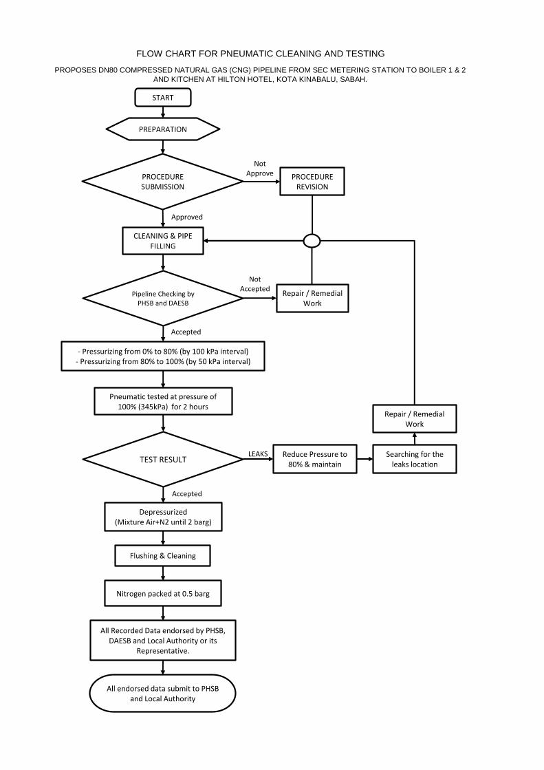
FLOW CHART FOR PNEUMATIC CLEANING AND TESTING
PROPOSES DN80 COMPRESSED NATURAL GAS (CNG) PIPELINE FROM SEC METERING STATION TO BOILER 1 & 2
AND KITCHEN AT HILTON HOTEL, KOTA KINABALU, SABAH.
START
PROCEDURE SUBMISSION
CLEANING & PIPE FILLING
PROCEDURE REVISION
Not Approve
Approved
Pipeline Checking by PHSB and DAESB
Repair / Remedial Work
Not Accepted
- Pressurizing from 0% to 80% (by 100 kPa interval) - Pressurizing from 80% to 100% (by 50 kPa interval)
Accepted
Pneumatic tested at pressure of 100% (345kPa) for 2 hours
TEST RESULT Reduce Pressure to
80% & maintain
LEAKS
Accepted
Searching for the leaks location
Repair / Remedial Work
PREPARATION
Depressurized (Mixture Air+N2 until 2 barg)
Flushing & Cleaning
Nitrogen packed at 0.5 barg
All Recorded Data endorsed by PHSB, DAESB and Local Authority or its
Representative.
All endorsed data submit to PHSB and Local Authority