flow control valve - bucher hydraulicsthe flow-control valve works with a control Δp of 12 bar. the...
TRANSCRIPT

Flow Control ValveSeries LVM..
1/12
Reference: 100-P-000126-EN-02
Issue: 03.2018
� high flow rates (180 l/min)
� flow rates are unaffected by temperature change or
when the higher load pressure alternates between the
outlet ports
� proportional flow-sharing principle
� easy to service
� reliable
� safe
1 Description
1.1 General description
Series LVM flow-control valves are used to set the speed of
single-acting hydraulic actuators. The flow rate is set by the
proportional or mechanical displacement of the control
spool.
The integral downstream pressure compensator makes it
possible to design systems that work on the principle of pro
portional flow-sharing (see section 10: Circuit examples).
There are 3 versions of the flow-control valve.
1.1.1 Load sensing (LS) pumps without 2-way pres
sure compensator
The Δp created by the LS pump determines the flow to the
actuator. The LS pressure is safeguarded by the integral
LSmax pressure relief function.
1.1.2 Load sensing (LS) pumps with 2-way pressure
compensator
The flow-control valve works with a control Δp of 12 bar. The
integral LSmax pressure relief limits the LS pressure. If it is
activated, the 2-way pressure compensator cuts off the flow
to the actuator, which then allows higher pressures to be de
veloped in the hydraulic system.
1.1.3 Fixed-displacement pumps with integral 3-way
pressure compensator
The flow that is not required is routed directly to tank.
1.2 Application examples
� Harvesters
� Sweepers
� Construction equipment
� Chippers/Shredders
� Municipal vehicles
� Asphalt pavers

100-P-000126-EN-02/03.2018
Flow Control Valve, LVM..2/12
2 Symbols
2.1 For load sensing pumps without
2-way pressure compensator
(LVM2W...)
P
A
1
2
T
X
3
optional
2.2 For load sensing pumps with 2-way
pressure compensator (LVM2C...)
P
T X A
1
2
3
optional
2.3 For fixed-displacement pumps with
integral 3-way pressure compensator
(LVM3C...)
P
T X A
MP
MT1
2
3
1 LS unloading (control valve, orifice, none)
2 LSmax pressure relief
3 spool type
2.4 Overview of variants
2.4.1 Spool type
A
T P
A
T P
version A version D
2.4.2 Pressure compensator
version 4B version 6version *
2.4.3 LS unloading
version 1 version 4 … 8 version *
2.4.4 LSmax pressure relief
version 1 version *

100-P-000126-EN-02/03.2018
Flow Control Valve, LVM..3/12
3 Technical data
IMPORTANT: Values refer to an oil viscosity of 35 mm2/s [cSt]. For others viscosities please contact Bucher Hydraulics.
General characteristics Unit Description, value
Design Monoblock
Seals NBR (Nitrile Butadiene rubber)
Operation Two-stage electrohydraulic, mechanical operation
Mounting attitude unrestricted
Electrical characteristics Unit Description, value
Design Proportional solenoid
Supply voltage V DC 12 or 24 from an electronic controller
Power consumption W max. 18 (at 1.5A and 12V, or 0.75A and 24V)
Dither frequency required Hz 100
Relative duty cycle at Imax % 100
Protection class (with a properly-fitted plug) AMP Junior Timer - IP65; Deutsch plug - IP67
Electrical connection AMP Junior Timer plug connector (2-pole); Deutsch plug
DT04-2P-EP04
Hydraulic characteristics Unit Description, value
Controlled-flow range l/min 16, 25, 32, 40, 50, 63, 80, 100, 125, 150 and 180
Nominal inlet flow, 3-way function l/min max. 180
Nominal inlet flow, 2-way function l/min max. 200
Maximum pressure at the inlet "P" bar max. 280
Maximum pressure at the outlet "T" bar 50 static
200 optional
Maximum pressure at the actuator ports bar max. 300
Fluid mineral oil to DIN 51524
Fluid temperature range °C -20 ... +80 (but comply with the viscosity limits)
Viscosity range mm2/s permitted: 10 ... 360
ideal: 20 ... 80
Minimum fluid cleanliness level ISO 4406 code 20/18/15

100-P-000126-EN-02/03.2018
Flow Control Valve, LVM..4/12
4 Performance graphsValues refer to an oil viscosity of 35 mm2/s [cSt].
4.1 Control characteristics
Electrohydraulically operated valve with 12 bar pressure
drop at the orifice. Q [l/min] = flow rate at the actuator port,
I [mA] = current at the solenoid
4.1.1 Flow characteristic LVM2W
0
20
40
60
80
100
120
140
160
180
500 600 700 800 900 1000 1100 1200 1300 1400
250 300 350 400 450 500 550 600 650 700
I [mA] 12V
I [mA] 24V
Q [l/m
in]
180
150
125
100
80
63
40
1500 1600
800750
50
32
25
16
4.1.2 Flow characteristic LVM2C
0
20
40
60
80
100
120
140
160
180
500 600 700 800 900 1000 1100 1200 1300 1400
250 300 350 400 450 500 550 600 650 700
I [mA] 12V
I [mA] 24V
Q [l/m
in]
180
150
125
100
80
63
40
1500 1600
800750
50
16
25
32
4.1.3 Flow characteristic LVM3C
0
20
40
60
80
100
120
140
160
180
500 600 700 800 900 1000 1100 1200 1300 1400
250 300 350 400 450 500 550 600 650 700
I [mA] 12V
I [mA] 24V
Q [l/m
in]
180
150
125
100
80
63
40
1500 1600800750
50
200
32
25
16
4.2 Unloaded bypass
4.2.1 LVM3C
0
5
10
15
20
25
30
35
40
50 100 150 200 250
Δp_P
->
T [bar]
QZU [l/min]
0
1
23
1 Control Δp 9 bar
2 Control Δp 12 bar (standard)
3 Control Δp 18 bar
100-P-000126-EN-02/03.2018
Flow Control Valve, LVM..5/12
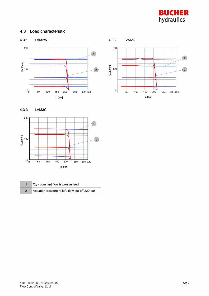
4.3 Load characteristic
4.3.1 LVM2W
50 100 150 200
QA
[l/m
in]
0
p [bar]
250 300 320
1
2
200
100
0
4.3.2 LVM2C
50 100 150 200
QA
[l/m
in]
0
p [bar]
250 300 320
1
2
200
100
0
4.3.3 LVM3C
50 100 150 200
QA
[l/m
in]
0
p [bar]
250 300 320
1
2
200
100
0
1 QA - constant flow is pressurised
2 Actuator pressure relief / flow cut-off 220 bar
100-P-000126-EN-02/03.2018
Flow Control Valve, LVM..6/12
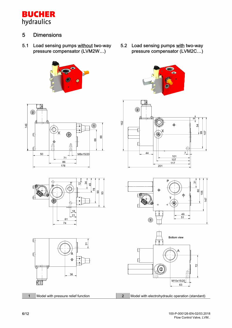
5 Dimensions
5.1 Load sensing pumps without two-way
pressure compensator (LVM2W…)
2
1
178
86
71
14
6
88
9390
34
45
21
61
18
74
12
78
66
31
36
50 M8x15/20
5.2 Load sensing pumps with two-way
pressure compensator (LVM2C…)
63
72
16
2
9
54
99
107
7
101
107
44
201117
31
80
105
147
4951
M10x15/20
1
2
Bottom view
1 Model with pressure relief function 2 Model with electrohydraulic operation (standard)
100-P-000126-EN-02/03.2018
Flow Control Valve, LVM..7/12
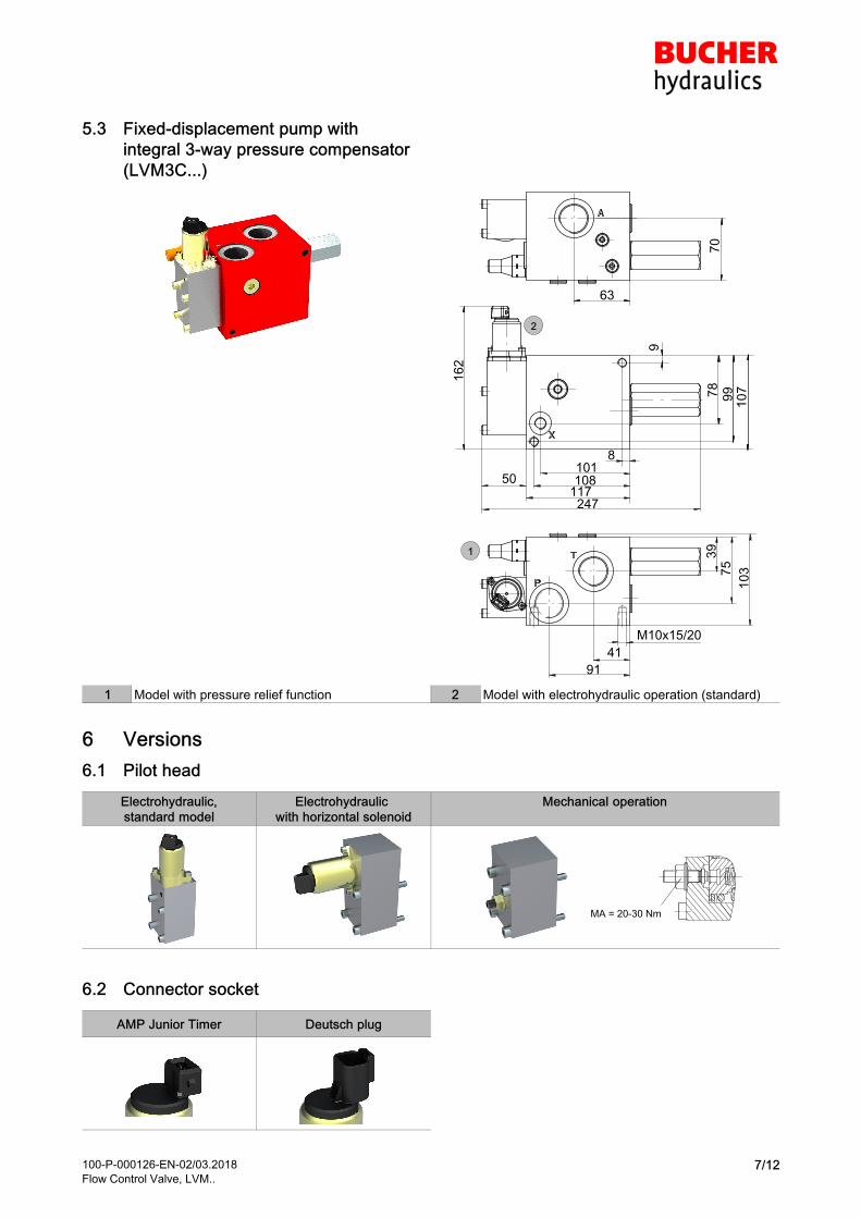
5.3 Fixed-displacement pump with
integral 3-way pressure compensator
(LVM3C...)
2
1
16
28
108
9
99
247
50117
10
7
70
63
39
41
91
75
78
101
103
M10x15/20
1 Model with pressure relief function 2 Model with electrohydraulic operation (standard)
6 Versions
6.1 Pilot head
Electrohydraulic,
standard model
Electrohydraulic
with horizontal solenoid
Mechanical operation
MA = 20-30 Nm
6.2 Connector socket
AMP Junior Timer Deutsch plug

100-P-000126-EN-02/03.2018
Flow Control Valve, LVM..8/12
7 Ordering code
L V M
Flow-control valve
without 2-way pressure comp. =2W
with 2-way pressure comp. =2C
with 3-way pressure comp. =3C
A 4 1 F J
P1 = pressure setting
in plain text
2-way = LS max
3-way = P max
0 52 W
Pilot head
Prop. electrohydraulic 12 V (standard) = F
Prop. electrohydraulic 24 V (standard) = G
Prop. electrohydraulic 12 V (horizontal) = T
Prop. electrohydraulic 24 V (horizontal) = U
Mechanical operation = M
Manual override
without = *
Override pin = A
Mechanical operation = N
Spool type (see chapter 2.4)
In 0 - position closed = A
in 0 - position open = D
0
Load sensing unloading
with LS unloading control = 1
without LS unloading control = *
LS unloading orifice 0,4 = 4
LS unloading orifice 0,5 = 5
LS unloading orifice 0,6 = 6
LS unloading orifice 0,7 = 7
LS unloading orifice 0,8 = 8
G 1 0 0 * 0 0 0 0 C / P1
Solenoid connector socket
AMP Junior-Timer = J
Deutsch DT04-2P-EP04 = T
with mechanical operation = *
Option
(to be inserted by the factory)
Maximum controlled flow
16 l/min = 016
25 l/min = 025
32 l/min = 032
40 l/min = 040
50 l/min = 050
63 l/min = 063
80 l/min = 080
100 l/min = 100
125 l/min = 125
150 l/min = 150
180 l/min = 180
Control Δp for compensator (2C, 3C)
Control Δp 9 bar (reduced) = E
Control Δp 12 bar (standard) = *
Control Δp 18 bar (raised) = H
E
Pressure compensator (load sensing)
Standard = 4
Damped = 6
Fine control = B
1
LSmax pressure relief
with LSmax pressure relief = 1
without = *
Port threads
to DIN 3852 - Part 2 or ISO 11926
2-way compensator (2W, 2C)
P and A G¾”
X (LS) and T G¼” = G100
P and A G1”
X (LS) and T G¼” = G110
3-way compensator (3C)
P and A G¾”
X (LS) G¼”
T G1” = G100
P, T and A G1”
X (LS) G¼” = G110
Design
(to be inserted by the factory)

100-P-000126-EN-02/03.2018
Flow Control Valve, LVM..9/12
8 Accessories
Description Type Order-No. Data sheet
Plug for AMP Junior Timer with 2 metres of cable Plug, Junior
Timer, 2-pin
100152575 -
Plug for Deutsch DT04-2P-EP04 with 2 metres of cable Deutsch
DT04-4P-CE09
100608468 -
9 Electronics
For controlling LVM… flow-control valves, we recommend
the ELSK106 series of control units and plug-in cards.
These are used to control 1 or 2 proportional solenoids and
can also operate on/off solenoids and other auxiliary func
tions. Plug-in cards are available and fully customised con
trol units can be supplied.
The following table contains a small selection of the
extensive range of accessories and electronics from
Bucher Hydraulics.
Type Description Order-No.
ELSK106-91*** with screw terminals 100018790
ELSK106-81*** with screw terminals, encapsulated 100018791
ELSK106-81***/02 with screw terminals, encapsulated, with ramp 2s 100013454
ELSK106-81***/04 with screw terminals, encapsulated, with ramp 4s 100026079
ESSK107 Multifunction card for controlling one proportional flow-
control valve (1 axis) and one on/off valve (e.g. seat
valve)
see data sheet
100-P-700033
ELSK106 Multifunction card for controlling one proportional flow-
control valve (1 axis) and one on/off valve (e.g. seat
valve)
See data sheet
100-P-700008
9.1 Examples of control units
ELSK 106 controller Description
Proportional amplifier module; front plate and indicator knob
ELSK 106-01***/11 controller Description
Makrolon® housing with rotary potentiometer, indicator knob,
LED and magnetic clamp

100-P-000126-EN-02/03.2018
Flow Control Valve, LVM..10/12
ELSK 106-02***/11 controller Description
Makrolon® housing with rotary potentiometer, indicator knob,
ON/OFF switch, LED and magnetic clamp
EBT control unit Description
The control unit consists of a solid aluminium enclosure with
impact-resistant plastic covers (IP65). The user-friendly oper
ating interface can be customised. The example shown isfitted with 1 rotary potentiometer (current output for propor
tional solenoid), 4 switches (detented or momentary), 1 ON/OFF switch.
Proportional amplifier EBM 300308-DS-MOBI Description
The EBM-300308-DS-MOBI proportional amplifier is used for
controlling three proportional directional valves (three axes /
six solenoids) or two proportional directional valves and onedirectional seat valve. The three axes can be controlled inde
pendently of one other. The current-compensation featureensures that the output current is unaffected by fluctuations
in the coil temperature or supply voltage.
10 Circuit examples
10.1 Circuit example of flow-control valve with 2-way pressure compensator
� Constant-pressure supply
� Load-independent drives using proportional flow-sharing
� Flow cut-off for belt-drive motor 1
� Unloading of actuator in neutral position
1 2
Pmax = 300 bar
Belt motor 1 Belt motor 2
T X A T X A
1 Flow-control valve with 2-way compensator,
with LS unloading and LS pressure relief:
LVM2C*080A41FJ1G110A0000C/P300
2 Flow-control valve with 2-way compensator,
without LS unloading or LS pressure relief:
LVM2C*050A4*FJ*G110A0000C
100-P-000126-EN-02/03.2018
Flow Control Valve, LVM..11/12
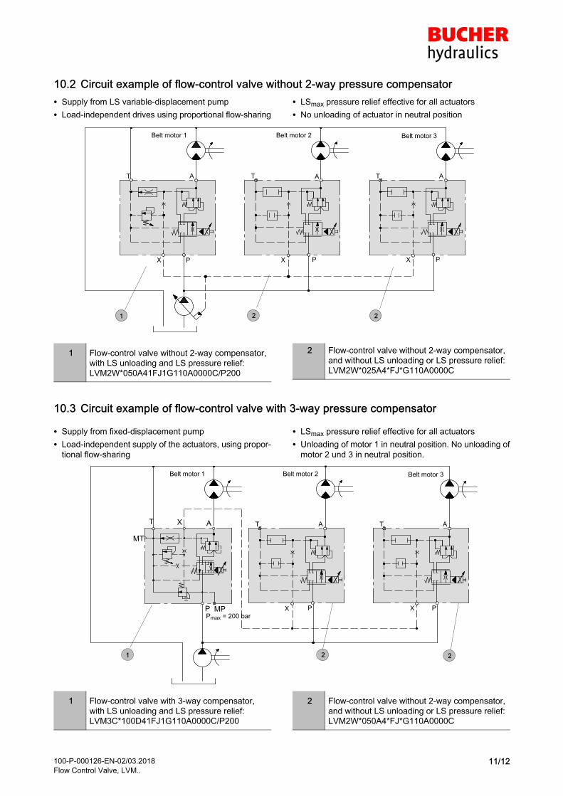
10.2 Circuit example of flow-control valve without 2-way pressure compensator
� Supply from LS variable-displacement pump
� Load-independent drives using proportional flow-sharing
� LSmax pressure relief effective for all actuators
� No unloading of actuator in neutral position
1 2
Pmax = 200 bar
2
Belt motor 1 Belt motor 2 Belt motor 3
P
AT
X P
AT
XP
AT
X
x x
1 Flow-control valve without 2-way compensator,
with LS unloading and LS pressure relief:
LVM2W*050A41FJ1G110A0000C/P200
2 Flow-control valve without 2-way compensator,
and without LS unloading or LS pressure relief:
LVM2W*025A4*FJ*G110A0000C
10.3 Circuit example of flow-control valve with 3-way pressure compensator
� Supply from fixed-displacement pump
� Load-independent supply of the actuators, using propor
tional flow-sharing
� LSmax pressure relief effective for all actuators
� Unloading of motor 1 in neutral position. No unloading of
motor 2 und 3 in neutral position.
1 2 2
Pmax = 200 bar
Belt motor 1 Belt motor 2 Belt motor 3
P
AT
XP
AT
XP
T X A
MP
MT
x
x x
1 Flow-control valve with 3-way compensator,
with LS unloading and LS pressure relief:
LVM3C*100D41FJ1G110A0000C/P200
2 Flow-control valve without 2-way compensator,
and without LS unloading or LS pressure relief:
LVM2W*050A4*FJ*G110A0000C

100-P-000126-EN-02/03.2018
Flow Control Valve, LVM..12/12
11 Fluid
Flow-control valves require fluid with a minimum
cleanliness level of ISO 4406 code 20/18/15.
We recommend the use of fluids that contain anti-wear
additives for operation with boundary lubrication. Fluids
without appropriate additives reduce the service life of the
valves.
The user is responsible for maintaining and regularly
checking of the fluid quality. Bucher Hydraulics
recommends a load capacity of > 30 N/mm2 to Brugger EN/
DIN 51347-2.
12 Note
This catalogue is intended for users with specialist
knowledge. The user must check the suitability of the
equipment described here in order to ensure that all of the
conditions necessary for the safety and proper functioning
of the system are fulfilled.
If you have any doubts or questions concerning the use of
these valves, please consult Bucher Hydraulics GmbH.
13 Fluid cleanliness
Cleanliness class to ISO 4406 and NAS 1638
Code
ISO 4406
Number of particles / 100 ml
≥ 4 m ≥ 6 m ≥ 14 m
23/21/18 8000000 2000000 250000
22/20/18 4000000 1000000 250000
22/20/17 4000000 1000000 130000
22/20/16 4000000 1000000 64000
21/19/16 2000000 500000 64000
20/18/15 1000000 250000 32000
19/17/14 500000 130000 16000
18/16/13 250000 64000 8000
17/15/12 130000 32000 4000
16/14/12 64000 16000 4000
16/14/11 64000 16000 2000
15/13/10 32000 8000 1000
14/12/9 16000 4000 500
13/11/8 8000 2000 250
� 2018 by Bucher Hydraulics GmbH, D-79771 Klettgau
All rights reserved.
Data is provided for the purpose of product description only, and must not be construed as warranted characteristics in the legal sense. The
information does not relieve users from the duty of conducting their own evaluations and tests. Because the products are subject to continual
improvement, we reserve the right to amend the product specifications contained in this catalogue.
Classification: 430.310.310.