flow control valve-model f2 - armstrong inc. · 2014-04-08 · armstrong information. armstrong 2...
TRANSCRIPT
Flow Control Valve-Model F2
Installation, Operation and Maintenance ManualIOM-441 - CPAC0014
Armstrong International221 Armstrong Blvd., Three Rivers, Michigan, 49093 - USAPh. (269) 279-3602 Toll Free (888) HOT-HOSE (468-4673) Fax (269) 279-3130

Designs, materials, weights and performance ratings are approximate and subject to change without notice. Visit armstronginternational.com/emech for up-to-date information.
Armstrong InternationalEmech™ Flow Control Valve- Model F2IOM-441 - CPAC0014
2
Flow Control Valve - Model F2 - Contents
Section / Description Page
Flow Control Valve - Model F2 - Introduction ......................................................................................................... 3
1.0 Flow Control Valve - Model F2 - Datasheet .................................................................................................... 4
Parts and Materials.................................................................................................................................... 5-6
Dimensions ................................................................................................................................................... 7
Specifications ............................................................................................................................................... 8
Operating Torque .......................................................................................................................................... 9
Performance ............................................................................................................................................... 10
2.0 Installation ......................................................................................................................................................11
3.0 Maintenance - Dismantling ............................................................................................................................ 12
4.0 Maintenance - Reassembly ............................................................................................................... 13, 14, 15
Legal Disclaimer ................................................................................................................................................... 16

Armstrong InternationalEmech™ Flow Control Valve- Model F2IOM-441 - CPAC0014
3
Designs, materials, weights and performance ratings are approximate and subject to change without notice. Visit armstronginternational.com/emech for up-to-date information.
IntroductionCongratulations on selecting the Emech™ product from Armstrong. Armstrong devotes considerable care and attention to the design of its products. To obtain the best performance from them, the customer should read this manual from cover to cover. It contains important installation and operating instructions.
The customer must strictly adhere to the safety tips, troubleshooting advice, cautions and warnings appearing throughout this manual. Along with the warnings, instructions and procedures in this manual, the customer should also observe such other procedures generally applicable to equipment of the same type.
If the customer does not follow these and other such warnings, instructions and procedures, the product may not perform as expected. More seriously, it may cause property damage, personal injury, production down-time and other losses.
The customer should train its employees and contractors in the safe use of Armstrong products in relation to the customer’s specific application. If the customer does not understand a point in this manual, contact Armstrong or its authorised representative.
Flow Control Valve - Model F2 - Introduction
Designs, materials, weights and performance ratings are approximate and subject to change without notice. Visit armstronginternational.com/emech for up-to-date information.
Armstrong InternationalEmech™ Flow Control Valve- Model F2IOM-441 - CPAC0014
4
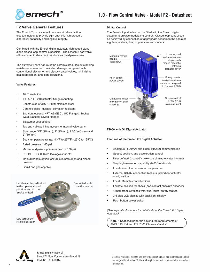
Manual overridehandle(not shown)
Push buttonpower switch
Graduated visualindicator on shaftcoupling
Local keypadand temperature
display with hinged magnetic
latchinglockable cover
Epoxy powdercoated aluminum
enclosure designedto Nema-4 (IP65)
Constructed ofCF8M (316)
stainless steel
Digital Control
The Emech 2 port valve can be fitted with the Emech digital actuator to provide modulating control. Closed loop control can be achieved by connection of appropriate sensors to the actuator e.g. temperature, flow, or pressure transducers.
F2050 with G1 Digital Actuator
Features of the Emech G1 Digital Actuator
• Analogue (4-20mA) and digital (Rs232) communication
• Speed, position, and acceleration control
• User defined ‘2-speed’ stroke can eliminate water hammer
• Very high resolution capability (0.03° rotational)
• Local closed loop control of Temperature
• External RS232 connection (cable supplied) for actuator configuration
• Local / Remote control options
• Failsafe position feedback (non-contact absolute encoder)
• 4 membrane switches with ‘dual touch’ safety feature
• 3.5 digit LCD display with back light display
• Push button power switch
(See separate document for details about the Emech G1 Digital Actuator.)
1.0 - Flow Control Valve - Model F2 - Datasheet
F2 Valve General FeaturesThe Emech 2 port valve utilizes ceramic shear action disc technology to provide tight shut-off, high pressure differential capability and long life integrity.
Combined with the Emech digital actuator, high speed stand alone closed loop control is possible. The Emech 2 port valve utilizes ceramic shear actions discs as the dynamic seal.
The extremely hard nature of the ceramic produces outstanding resistance to wear and cavitation damage compared with conventional elastomer and plastic seated valves, minimizing seal replacement and plant downtime.
Valve Features
• 1/4 Turn Action
• ISO 5211, 5210 actuator flange mounting
• Constructed of 316 (CF8M) stainless steel
• Ceramic discs - durable, corrosion resistant
• End connections: NPT, ASME Cl. 150 Flanges, Socket Weld, Sanitary Styled Flanges
• Elastomer seal options
• Top entry allows inline access to internal valve parts
• Size range: 3/4” (20 mm), 1” (25 mm), 1 1/2” (40 mm) and 2” (50 mm)
• Body temperature range: -13°F to 257°F (-25°C to 125°C)
• Rated pressure: 145 psi
• Maximum dynamic pressure drop of 130 psi
• BUBBLE TIGHT (zero leakage) shut-off*
• Manual handle option lock-able in both open and closed position
• Liquid and gas capable
Handle can be padlockedin the open or closedposition, and can be'stroke limited'
Graduated scaleon the handle
Low torque °stroke operation
90Note: * Seat seal performs beyond the requirements of ANSI B16.104 and FCI 70-2, Classes V and VI.
Armstrong InternationalEmech™ Flow Control Valve- Model F2IOM-441 - CPAC0014
5
Designs, materials, weights and performance ratings are approximate and subject to change without notice. Visit armstronginternational.com/emech for up-to-date information.
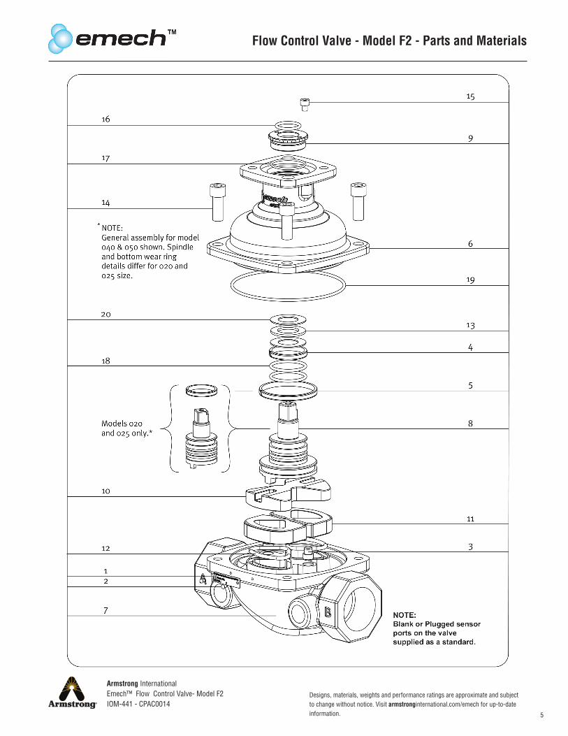
Flow Control Valve - Model F2 - Parts and Materials
Designs, materials, weights and performance ratings are approximate and subject to change without notice. Visit armstronginternational.com/emech for up-to-date information.
Armstrong InternationalEmech™ Flow Control Valve- Model F2IOM-441 - CPAC0014
6
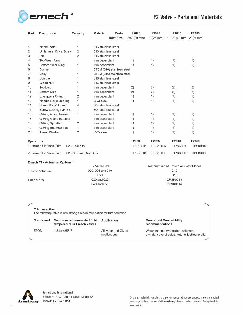
F2 Valve - Parts and Materials
Part Description Quantity Material Code:Inlet Size:
F20203/4” (20 mm)
F20251” (25 mm)
F20401-1/2” (40 mm)
F20502” (50mm)
1234567891011121314151617181920
Name PlateU Hammer Drive ScrewPinTop Wear RingBottom Wear RingBonnetBodySpindleGland NutTop DiscBottom DiscEnergizers O-ringNeedle Roller BearingScrew Body/BonnetScrew Locking (M4 x 6)O-Ring Gland InternalO-Ring Gland ExternalO-Ring SpindleO-Ring Body/BonnetThrust Washer
12211111111214111212
316 stainless steel316 stainless steel316 stainless steeltrim dependenttrim dependentCF8M (316) stainless steelCF8M (316) stainless steel316 stainless steel316 stainless steeltrim dependenttrim dependenttrim dependentC-Cr steel304 stainless steel304 stainless steeltrim dependenttrim dependenttrim dependenttrim dependentC-Cr steel
1) 1) 1) 1)1) 1) 1) 1)
2) 2) 2) 2)2) 2) 2) 2)1) 1) 1) 1)1) 1) 1) 1)
1) 1) 1) 1)1) 1) 1) 1)1) 1) 1) 1)1) 1) 1) 1)1) 1) 1) 1)
Spare Kits:1) Included in Valve Trim
2) Included in Valve Trim
F2 - Seal Kits
F2 - Ceramic Disc Sets
CPSK0001
CPSK0005
CPSK0002
CPSK0006
CPSK0017
CPSK0007
CPSK0018
CPSK0008
Emech F2 - Actuation Options:
Electric Actuators
Handle Kits
F2 Valve Size020, 025 and 040
050020 and 025040 and 050
Recommended Emech Actuator ModelG12G13
CPSK0013CPSK0014
Trim selectionThe following table is Armstrong’s recommendation for trim selection.
Compound Maximum recommended fluidtemperature in Emech valves
Application Compound Compatibilityrecommendations
EPDM -13 to +257°F All water and Glycol applications.
Water, steam, hydroxides, solvents, alchols, several acids, ketone & silicone oils.
F2020 F2025 F2040 F2050
Armstrong InternationalEmech™ Flow Control Valve- Model F2IOM-441 - CPAC0014
7
Designs, materials, weights and performance ratings are approximate and subject to change without notice. Visit armstronginternational.com/emech for up-to-date information.
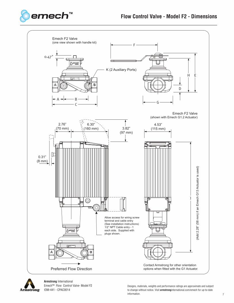
4.53”(115 mm)3.82”
(97 mm)
6.30”(160 mm)
2.76”(70 mm)
0.31”(8 mm)
Contact Armstrong for other orientationoptions when fitted with the G1 Actuator.
Allow access for wiring screwterminal and cable entry (See installation instructions)1/2” NPT Cable entry - 1 each side. Supplied with plugs shown.
K (2 Auxiliary Ports)
Emech F2 Valve(one view shown with handle kit)
Emech F2 Valve(shown with Emech G1.2 Actuator)
Preferred Flow Direction
Flow Control Valve - Model F2 - Dimensions
Designs, materials, weights and performance ratings are approximate and subject to change without notice. Visit armstronginternational.com/emech for up-to-date information.
Armstrong InternationalEmech™ Flow Control Valve- Model F2IOM-441 - CPAC0014
8
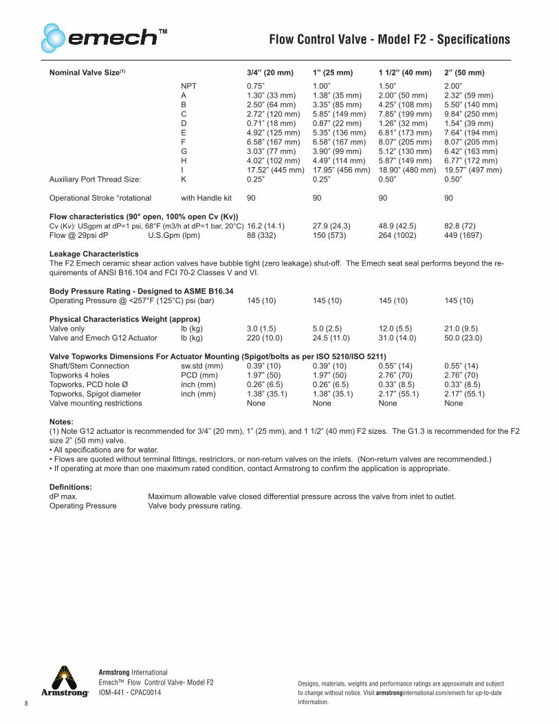
Nominal Valve Size(1) 3/4” (20 mm) 1” (25 mm) 1 1/2” (40 mm) 2” (50 mm) NPT 0.75” 1.00” 1.50” 2.00” A 1.30” (33 mm) 1.38” (35 mm) 2.00” (50 mm) 2.32” (59 mm) B 2.50” (64 mm) 3.35” (85 mm) 4.25” (108 mm) 5.50” (140 mm) C 2.72” (120 mm) 5.85” (149 mm) 7.85” (199 mm) 9.84” (250 mm) D 0.71” (18 mm) 0.87” (22 mm) 1.26” (32 mm) 1.54” (39 mm) E 4.92” (125 mm) 5.35” (136 mm) 6.81” (173 mm) 7.64” (194 mm) F 6.58” (167 mm) 6.58” (167 mm) 8.07” (205 mm) 8.07” (205 mm) G 3.03” (77 mm) 3.90” (99 mm) 5.12” (130 mm) 6.42” (163 mm) H 4.02” (102 mm) 4.49” (114 mm) 5.87” (149 mm) 6.77” (172 mm) I 17.52” (445 mm) 17.95” (456 mm) 18.90” (480 mm) 19.57” (497 mm)Auxiliary Port Thread Size: K 0.25” 0.25” 0.50” 0.50”
Operational Stroke °rotational with Handle kit 90 90 90 90 Flow characteristics (90° open, 100% open Cv (Kv))Cv (Kv): USgpm at dP=1 psi, 68°F (m3/h at dP=1 bar, 20°C) 16.2 (14.1) 27.9 (24.3) 48.9 (42.5) 82.8 (72)Flow @ 29psi dP U.S.Gpm (lpm) 88 (332) 150 (573) 264 (1002) 449 (1697)
Leakage Characteristics The F2 Emech ceramic shear action valves have bubble tight (zero leakage) shut-off. The Emech seat seal performs beyond the re-quirements of ANSI B16.104 and FCI 70-2 Classes V and VI.
Body Pressure Rating - Designed to ASME B16.34Operating Pressure @ <257°F (125°C) psi (bar) 145 (10) 145 (10) 145 (10) 145 (10)
Physical Characteristics Weight (approx)Valve only lb (kg) 3.0 (1.5) 5.0 (2.5) 12.0 (5.5) 21.0 (9.5)Valve and Emech G12 Actuator lb (kg) 220 (10.0) 24.5 (11.0) 31.0 (14.0) 50.0 (23.0)
Valve Topworks Dimensions For Actuator Mounting (Spigot/bolts as per ISO 5210/ISO 5211)Shaft/Stem Connection sw.std (mm) 0.39” (10) 0.39” (10) 0.55” (14) 0.55” (14) Topworks 4 holes PCD (mm) 1.97” (50) 1.97” (50) 2.76” (70) 2.76” (70) Topworks, PCD hole Ø inch (mm) 0.26” (6.5) 0.26” (6.5) 0.33” (8.5) 0.33” (8.5)Topworks, Spigot diameter inch (mm) 1.38” (35.1) 1.38” (35.1) 2.17” (55.1) 2.17” (55.1)Valve mounting restrictions None None None None
Notes:(1) Note G12 actuator is recommended for 3/4” (20 mm), 1” (25 mm), and 1 1/2” (40 mm) F2 sizes. The G1.3 is recommended for the F2 size 2” (50 mm) valve.• All specifications are for water.• Flows are quoted without terminal fittings, restrictors, or non-return valves on the inlets. (Non-return valves are recommended.)• If operating at more than one maximum rated condition, contact Armstrong to confirm the application is appropriate.
Definitions:dP max. Maximum allowable valve closed differential pressure across the valve from inlet to outlet.Operating Pressure Valve body pressure rating.
Flow Control Valve - Model F2 - Specifications
Armstrong InternationalEmech™ Flow Control Valve- Model F2IOM-441 - CPAC0014
9
Designs, materials, weights and performance ratings are approximate and subject to change without notice. Visit armstronginternational.com/emech for up-to-date information.
Flow Control Valve - Model F2 - Operating Torque
Emech F2-Standard Model Codes:Model Code Description End Connection Flow Control Unit Codes F2020 F2 VALVE 3/4” (20mm) NPT Screwed NPT E20F F2025 F2 VALVE 1” (25mm) NPT Screwed NPT E25F F2040 F2 VALVE 1-1/2” (40mm) NPT Screwed NPT E40F F2050 F2 VALVE 2” (50mm) NPT Screwed NPT E50F
Emech F2- Model Codes on request:Model Code Description End Connection Flow Control Unit Codes D48916 F2 Valve 1”(25mm) SW Socket Weld ASME B16.34 F2040R F2 VALVE 1-1/2”(40mm) FLG Flanged ASME CL.150 E40FR F2050R F2 VALVE 2”(50mm) FLG Flanged ASME CL.150 E50FR F2050RH F2 VALVE 2”(50mm)SANITARY FLG Flanged ASME CL.150
The Flow Control Units includes Valve, Actuator, Mounting Kit, Serial Cable, Temperature Sensor, CD, Spanner and all relevant IOM's.
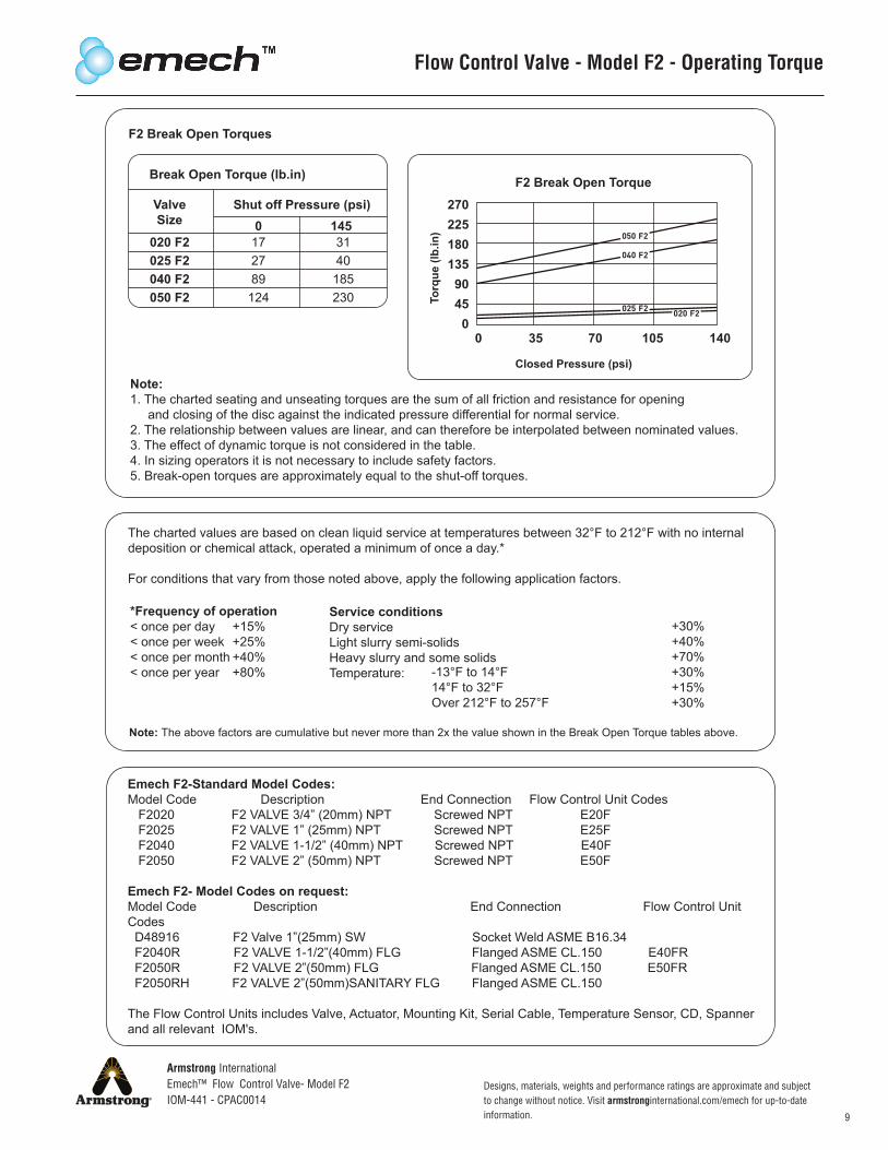
Note:1. The charted seating and unseating torques are the sum of all friction and resistance for opening and closing of the disc against the indicated pressure differential for normal service.2. The relationship between values are linear, and can therefore be interpolated between nominated values.3. The effect of dynamic torque is not considered in the table.4. In sizing operators it is not necessary to include safety factors.5. Break-open torques are approximately equal to the shut-off torques.
The charted values are based on clean liquid service at temperatures between 32°F to 212°F with no internaldeposition or chemical attack, operated a minimum of once a day.*
For conditions that vary from those noted above, apply the following application factors.
Note: The above factors are cumulative but never more than 2x the value shown in the Break Open Torque tables above.
*Frequency of operation< once per day +15%< once per week +25%< once per month +40%< once per year +80%
Service conditionsDry serviceLight slurry semi-solidsHeavy slurry and some solidsTemperature: -13°F to 14°F
14°F to 32°FOver 212°F to 257°F
+30%+40%+70%+30%+15%+30%
F2 Break Open Torques
Break Open Torque (lb.in)
ValveSize
Shut off Pressure (psi)
020 F2025 F2040 F2050 F2
172789
124
3140
185230
0 145
F2 Break Open Torque
Closed Pressure (psi)
27022518013590450
0 35 70 105 140
Designs, materials, weights and performance ratings are approximate and subject to change without notice. Visit armstronginternational.com/emech for up-to-date information.
Armstrong InternationalEmech™ Flow Control Valve- Model F2IOM-441 - CPAC0014
10
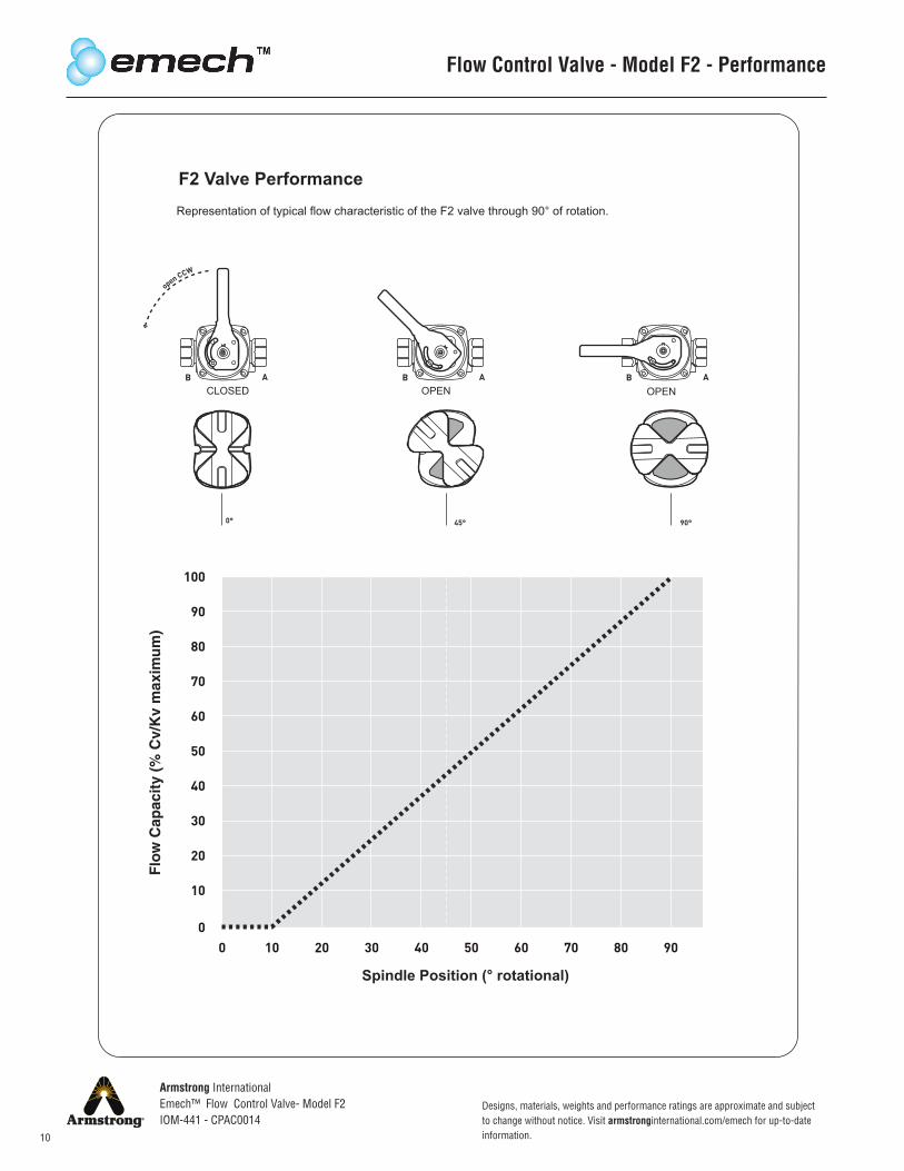
F2 Valve PerformanceRepresentation of typical flow characteristic of the F2 valve through 90° of rotation.
CLOSED OPEN OPEN
Spindle Position (° rotational)
Flow Control Valve - Model F2 - Performance
Armstrong InternationalEmech™ Flow Control Valve- Model F2IOM-441 - CPAC0014
11
Designs, materials, weights and performance ratings are approximate and subject to change without notice. Visit armstronginternational.com/emech for up-to-date information.
050 F2
040 F2
025 F2
020 F2
4248 lbf.in (480 Nm)
2124 lbf.in (240 Nm)
920 lbf.in (105 Nm)
496 lbf.in (55 Nm)
1150 lbf.in (130 Nm)
1150 lbf.in (130 Nm)
1150 lbf.in (130 Nm)
620 lbf.in (70 Nm)
360 lbf. (1600 N)
144 lbf. (640 N)
72 lbf. (320 N)
45 lbf. (200 N)
450 lbf. (2000 N)
180 lbf. (800 N)
90 lbf. (400 N)
56 lbf. (250 N)
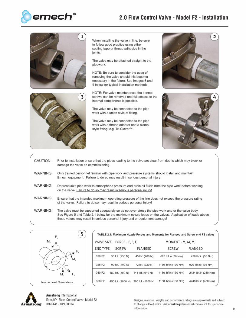
TABLE 2.1: Maximum Nozzle Forces and Moments for Flanged and Screw end F2 valves
Nozzle Load Orientations
2.0 Flow Control Valve - Model F2 - Installation
When installing the valve in line, be sureto follow good practice using eithersealing tape or thread adhesive in the joints.
The valve may be attached straight to the pipework.
NOTE: Be sure to consider the ease ofremoving the valve should this becomenecessary in the future. See images 3 and4 below for typical installation methods.
NOTE: For valve maintenance, the bonnetscrews can be removed and full access to the internal components is possible.
The valve may be connected to the pipework with a union style of fitting.
The valve may be connected to the pipework with a thread adapter and a clampstyle fitting. e.g. Tri-Clover™.
CAUTION:
WARNING:
WARNING:
WARNING:
WARNING:
Prior to installation ensure that the pipes leading to the valve are clear from debris which may block or damage the valve on commissioning.
Only trained personnel familiar with pipe work and pressure systems should install and maintainEmech equipment. Failure to do so may result in serious personal injury!
Depressurize pipe work to atmospheric pressure and drain all fluids from the pipe work before workingon the valve. Failure to do so may result in serious personal injury!
Ensure that the intended maximum operating pressure of the line does not exceed the pressure ratingof the valve. Failure to do so may result in serious personal injury!
The valve must be supported adequately so as not over stress the pipe work and or the valve body.See Figure 5 and Table 2.1 below for the maximum nozzle loads on the valves. Application of loads above these values may result in serious personal injury and or equipment damage!
Designs, materials, weights and performance ratings are approximate and subject to change without notice. Visit armstronginternational.com/emech for up-to-date information.
Armstrong InternationalEmech™ Flow Control Valve- Model F2IOM-441 - CPAC0014
12
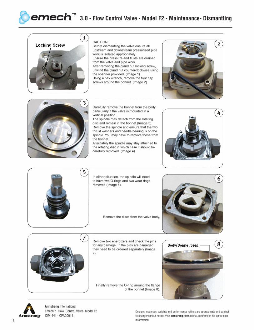
3.0 - Flow Control Valve - Model F2 - Maintenance- Dismantling
CAUTION!Before dismantling the valve,ensure all upstream and downstream pressurised pipe work is isolated appropriately.Ensure the pressure and fluids are drained from the valve and pipe work. After removing the gland nut locking screw, unwind the gland nut counterclockwise using the spanner provided. (Image 1)Using a hex wrench, remove the four cap screws around the bonnet. (Image 2)
Carefully remove the bonnet from the body particularly if the valve is mounted in a vertical position.The spindle may detach from the rotating disc and remain in the bonnet.(Image 3). Remove the spindle and ensure that the two thrust washers and needle bearing is on the spindle. You may have to remove these from the bonnet.Alternately the spindle may stay attached to the rotating disc in which case it should be carefully removed. (Image 4)
In either situation, the spindle will need to have two O-rings and two wear rings removed (Image 5).
Remove the discs from the valve body.
Remove two energizers and check the pins for any damage. If the pins are damaged they need to be ordered separately (Image 7).
Finally remove the O-ring around the flange of the bonnet (Image 8).
Armstrong InternationalEmech™ Flow Control Valve- Model F2IOM-441 - CPAC0014
13
Designs, materials, weights and performance ratings are approximate and subject to change without notice. Visit armstronginternational.com/emech for up-to-date information.
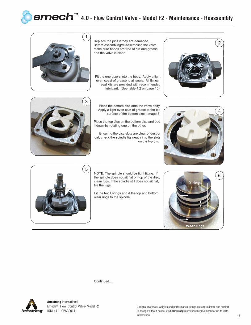
4.0 - Flow Control Valve - Model F2 - Maintenance - Reassembly
Replace the pins if they are damaged.Before assembling/re-assembling the valve, make sure hands are free of dirt and grease and the valve is clean.
Fit the energizers into the body. Apply a light even coast of grease to all seals. All Emech
seal kits are provided with recommended lubricant. (See table 4.2 on page 15).
Place the bottom disc onto the valve body. Apply a light even coat of grease to the top
surface of the bottom disc. (Image 3)
Place the top disc on the bottom disc and bed it down by rotating one on the other.
Ensuring the disc slots are clear of dust or dirt, check the spindle fits neatly into the slots
on the top disc.
NOTE: The spindle should be tight fitting. If the spindle does not sit flat on top of the disc, clean lugs. If the spindle still does not sit flat, file the lugs.
Fit the two O-rings and d the top and bottom wear rings to the spindle.
Continued....
Designs, materials, weights and performance ratings are approximate and subject to change without notice. Visit armstronginternational.com/emech for up-to-date information.
Armstrong InternationalEmech™ Flow Control Valve- Model F2IOM-441 - CPAC0014
14
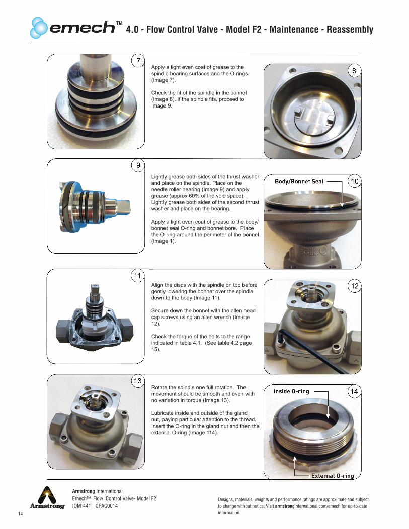
Align the discs with the spindle on top before gently lowering the bonnet over the spindle down to the body (Image 11).
Secure down the bonnet with the allen head cap screws using an allen wrench (Image 12).
Check the torque of the bolts to the range indicated in table 4.1. (See table 4.2 page 15).
4.0 - Flow Control Valve - Model F2 - Maintenance - Reassembly
Apply a light even coat of grease to the spindle bearing surfaces and the O-rings (Image 7).
Check the fit of the spindle in the bonnet (Image 8). If the spindle fits, proceed to Image 9.
Lightly grease both sides of the thrust washer and place on the spindle. Place on the needle roller bearing (Image 9) and apply grease (approx 60% of the void space). Lightly grease both sides of the second thrust washer and place on the bearing.
Apply a light even coat of grease to the body/bonnet seal O-ring and bonnet bore. Place the O-ring around the perimeter of the bonnet (Image 1).
Rotate the spindle one full rotation. The movement should be smooth and even with no variation in torque (Image 13).
Lubricate inside and outside of the gland nut, paying particular attention to the thread. Insert the O-ring in the gland nut and then the external O-ring (Image 114).
Armstrong InternationalEmech™ Flow Control Valve- Model F2IOM-441 - CPAC0014
15
Designs, materials, weights and performance ratings are approximate and subject to change without notice. Visit armstronginternational.com/emech for up-to-date information.
15
16
17
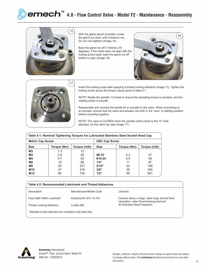
Table 4.1: Nominal Tightening Torques for Lubricated Stainless Steel Socket Head Cap
Metric Cap Screw UNC Cap Screw
Size Torque (Nm) Torque (inlb) Size Torque (Nm) Torque (inlb)
Table 4.2: Recommended Lubricants and Thread Adhesives
M3M4M5M6M8M10M12
1.32.95.710254782
12265089221416726
3.35.511223995
274997195345841
#8-32#10-241/4”5/16”3/8”1/2”
Description Manufacturer/Model Code Used for:
Food Safe Teflon Lubricant* Klubersynth UH1 14-151 Ceramic discs; o-rings; wear rings; bonnet borelubrication; roller thrust bearing lubricantAll Stainless Steel FastenersThread Locking Adhesive Loctite 262
*Sachets of this lubricant are included in the Seal Kits.
“Zero”Notch
4.0 - Flow Control Valve - Model F2 - Maintenance - Reassembly
With the gland wench provided, screw the gland nut down until it bottoms out. Do not over-tighten! (Image 15).
Back the gland nut off 3 notches (70 degrees). If the notch does not align with the locking screw head, back the gland nut off further to align (Image 16).
Insert the locking screw after applying a thread locking adhesive (Image 17). Tighten the locking screw as per the torque values given in table 4.1.
NOTE: Rotate the spindle 1-2 times to ensure the operating torque is constant, and the rotating action is smooth.
Reassemble and connect the handle kit or actuator to the valve. When connecting to an actuator, ensure that the valve and actuator are both in the “zero” or starting position before mounting together.
NOTE: The valve is CLOSED when the spindle notch points to the “0” markstamped on the valve top (see Image 17).

Armstrong InternationalEmech™ Flow Control Valve- Model F2IOM-441 - CPAC0014
16
Armstrong Hot Water Group, Inc. (“Armstrong”) warrants to the original user of those products supplied by it and used in the service and in the manner for which they are intended, that such products shall be free from defects in material and workmanship for a period of one (1) year from the date of installation, but not longer than 15 months from the date of shipment from the factory [unless a Special Warranty Period applies, as listed below]. This warranty does not extend to any product that has been subject to misuse, neglect, or alteration after shipment from the Armstrong factory. Except as may be expressly provided in a written agreement between Armstrong and the user, which is signed by both parties, Armstrong DOES NOT MAKE ANY OTHER REPRESENTATIONS OR WARRANTIES, EXPRESS OR IMPLIED, INCLUDING, BUT NOT LIMITED TO, ANY IMPLIED WARRANTY OF MERCHANTABILITY OR ANY IMPLIED WARRANTY OF FITNESS FOR A PARTICULAR PURPOSE.
The sole and exclusive remedy with respect to the above limited warranty or with respect to any other claim relatingto the products or to defects or any condition or use of the products supplied by Armstrong, however caused,and whether such claim is based upon warranty, contract, negligence, strict liability, or any other basis or theory, islimited to Armstrong’s repair or replacement of the part or product, excluding any labor or any other cost to remove or install said part or product, or, at Armstrong’s option, to repayment of the purchase price. As a condition of enforcing any rights or remedies relating to Armstrong products, notice of any warranty or other claim relating to the products must be given in writing to Armstrong: (i) within 30 days of last day of the applicable warranty period, or (ii) within 30 days of the date of the manifestation of the condition or occurrence giving rise to the claim, whichever is earlier. IN NO EVENT SHALL ARMSTRONG BE LIABLE FOR SPECIAL, DIRECT, INDIRECT, INCIDENTAL OR CONSEQUENTIAL DAMAGES, INCLUDING, BUT NOT LIMITED TO, LOSS OF USE OR PROFITS OR INTERRUPTION OF BUSINESS. The Limited Warranty and Remedy terms herein apply notwithstanding any contrary terms in any purchase order or form submitted or issued by any user, purchaser, or third party and all such contrary terms shall be deemed rejected by Armstrong.
Legal Disclaimer