flow features and industrial applications of tse ... · flow features and industrial applications...
TRANSCRIPT

Copyright c© 2007 Tech Science Press FDMP, vol.3, no.2, pp.129-146, 2007
Flow Features and Industrial Applications of TSE Rheoextrusion Process
H. Tang1, L.C. Wrobel2, and Z. Fan2
Abstract: This paper presents an overview ofdiverse extrusion techniques and, in particular, afocused discussion about the rheoextrusion pro-cess for semi-solid casting (a novel casting pro-cess for the fabrication of high quality metals).The review reveals a wealth of interesting rhe-ological and microstructural features, illustratingqualitative and quantitative data. The analysis issupported by relevant numerical results and ex-amples. It is shown how numerical studies canlead to significant insights into these processesby providing more detailed information on thefundamental mechanisms of morphology devel-opment (during phase change) and profile form-ing. The die filling and solidification behaviourswithin extrusion dies are simulated numerically.The extrusion forming process is also investigatedand compared with experimental results. The nu-merical results show that the profiles of velocityand solidified front of semi-solid metals (SSM)within the die will influence the final microstruc-ture of casts, both in the interior and on the sur-face. Finally, an industrial application employinga special patented concept design is presented andanalysed.
Keyword: Rheoextrusion, semi-solid metals,die filling, metal forming, solidification
1 Introduction
Extrusion is a manufacturing process widely usedto produce parts and components for the con-struction industry (PVC window profiles, pipesand tubes), automotive industry (rubber seals, gas
1 Corresponding author. E-mail: [email protected] of Energy and Power Engineering, Nanjing Uni-versity of Aeronautics and Astronautics, Nanjing, 210016,China.
2 School of Engineering and Design, Brunel University,Uxbridge, Middlesex UB8 3PH, UK
conducts), biomedical industry (medical tubing),textile industry (nylon fiber), etc. The twin-screwextrusion (TSE) die process for semi-solid andimmiscible alloy casting was developed prototyp-ically (Roberts et al., 2002), and has been used inthe above areas as a mixing process before extru-sion, and also in food processing. After flowingaround the rotating twin-screw, melt material en-ters the final die whose function is to transformthe circular flow section at the end of the screwinto the complex shape of the die lip. Rheoex-trusion casting by TSE provides excellent mi-crostructure metallurgical characteristics in semi-solid and immiscible alloy casting, which are po-tential products for automotive components.
There is an increasing need to be able to controlthese complex metallurgical processes, requiringan improved capability to numerically simulateand study these processes (Amberg and Shiomi,2005). Numerical simulations are, in principle,ideally suited to study these complex multiphaseflows and provide an insight into the process thatis difficult to obtain experimentally (Abhilash,Joseph and Krishna, 2006; Hong Zhu, and Lee,2006; and Narski and Picasso, 2007). Though nu-merical simulators have been developed for poly-mer melt flow in TSE extrusion, and for the re-heat metal material extrusion process, there areno available studies for the simulation of liquidmetallurgical alloy flow in TSE extrusion. As thisinvolves both complex rheological and metallur-gical behaviours, these flows present interestingtechnological challenges.
Numerical simulation of rheoextrusion casting byTSE can be categorised into two sub-processes:the first involves the rheological behaviour of themetal flow inside TSE, where multiphase mixingand the transition from turbulent to laminar flowappear; the second sub-process is dominated by

130 Copyright c© 2007 Tech Science Press FDMP, vol.3, no.2, pp.129-146, 2007
semi-solid flow, including solidification, die fill-ing and metal forming processes.
The paper runs as follows: Section 2 presents a re-view of the existing literature; Section 3 focuseson the analysis of the rheoextrusion process; Sec-tion 4 introduces numerical methods for rheoex-trusion; Section 5 shows numerical investigationsand predictions; Section 6 presents design ap-proaches for industrial applications; finally, con-cluding remarks are given in Section 7.
2 Literature review
Numerical simulations of extrusion processes aremainly related to melt polymers as well as ap-plications to food and pharmaceutical processes.Numerical simulations of extrusions for metalprocess are carried out mainly for thixo-extrusion,including cold extrusion, hot extrusion and semi-solid extrusion. A review of applications tothe extrusion bending process is not includedhere, but a recent review paper was published byVollertsen et al. (1999).
2.1 Simulations of extrusion process
Extrusion is a process used to manufacture prod-ucts in the form of continuous lengths with a uni-form cross section. This section can be quite sim-ple, i.e. circular, annular or rectangular profiles,or very complex.
Numerical simulations of extrusion have been ap-plied successfully to various cases in polymer en-gineering. The aim of the simulations is to inves-tigate the following aspects:
(1) Rheological behaviour, including solid frac-tion, liquid pressure, temperature distribution,flow pattern, velocity profiles, filling process.
(2) Die profile design with these parameters(Carneiro et al., 2001).
(3) Extrusion shape prediction, inverse extrusioncapability (Gejadze and Jarny, 2002).
(4) Process design: performance of extrusionprocess, cooling rate, velocity, and controltemperature.
The numerical simulations are generally con-ducted considering the flow as viscoelastic, andare also used in the food and pharmaceutical in-dustries (Elsey et al., 1999), to process materialssuch as flour (Li, 1999) and paste (Aydin et al.,2000). Typical results of numerical simulationsof polymer extrusion are shown in Figure 1.
Numerical simulations of extrusion are also per-formed in metal processing for the investigationof metal forming, where billet aluminium alloysare materials commonly used for cold extrusion(Mehta et al., 2000; Lee et al., 2002; MacCor-mack and Monaghan, 2002), for hot extrusion(Skauvik, 1999; Bjork et al., 1999; Kang et al.,2002), for semi-solid extrusion (Hwang et al.,2000; Ward et al., 2000; Yoon et al., 1999), aswell as for some other metals, such as magnesium(Ogawa et al., 2002). The aims of the simula-tions are similar to those listed above (e.g. diedesign (Hao and Li, 2000)), but more focused ondefect prediction, frictional models for contacts orbearings (Lof, 2001; Lee and Im, 1999), cross-shape transforming (Celik and Chitkara, 2002),strain distribution (Liu et al., 1999), microstruc-ture (Lee et al., 2000), etc. The main differencefor metals is that numerical simulations are con-ducted assuming rigid viscoplastic or plastic flows(Rosochowski and Olejnik, 2002). A typical sim-ulation result for metal extrusion is shown in Fig-ure 2 (Mehta et al., 2000).
Simulations of liquid melts flowing through ex-truder dies have not appeared in the literature yetbecause liquid metal extrusion is a newly devel-oped process. The simulation of rheoextrusionis different from existing extrusion simulation ap-proaches in the following three aspects:
• Existing simulation approaches for moltenflow assume a laminar viscoelastic flow,which is mostly appropriate for polymers;
• The metal flowing within a rheoextrusion dieis a semi-solid, thus phase change and heattransfer dominate the whole process;
• Although rheoextrusion is a liquid metal ex-trusion process, it differs from conventional

Flow Features and Industrial Applications of TSE Rheoextrusion Process 131
Figure 1: Results of simulations using Polyflow (Polyflow, 2002)
Figure 2: Effective stress distribution for a streamlined die extrusion simulation, left for DEFORM-3D R©,right for MSC SuperForge (Mehta et al., 2000)
liquid casting processes involving the solidi-fication of a pure liquid shell.
2.2 Applications of numerical simulations
There are several packages available for the nu-merical simulation of extrusion processes, bothfor viscoelastic and rigid viscoplastic flow, asshown in Table 1.
The BEMflow and PolyFlow codes can be used tosimulate TSE and extrusion of viscoelastic flows;Polyflow, in particular, is widely used for TSE inpolymer engineering. The code was developed by
Polyflow s.a., founded in Belgium in 1988 andlater integrated in the Fluent Inc. group in 1997.Polyflow is mostly focused on the polymer andrubber processing industry. BEMflow is a newlydeveloped code based on the boundary elementmethod. FIDAP is a widely used general CFDcode which can simulate extrusion processes bothfor polymer and metals, e.g. die extrusion of alu-minium (Skauvik, 1999) and continuous castingof aluminium alloys (Li, 1997). A typical exam-ple of simulation is shown in Figure 3. The mostpopular CAE/CAM codes are DEFORM-3D and

132 Copyright c© 2007 Tech Science Press FDMP, vol.3, no.2, pp.129-146, 2007
Table 1: Simulation software for extrusion die processes
Packages Developer/Organization Features Reference1. Commercial CFD codes for extrusion die processBEMflow Madison Group, USA BEM 3D, TSE polymer (BEMflow)PolyFlow Fluent Inc., Polyflow SA,
BelgiumFEM 3D, TSE polymer (Polyflow, 2002)
FiDAP Fluent Inc., USA FEM 3D, metal (Skauvik, 1999)2. Commercial CAE/CAM codes for metal extrusion processMSC Superform MSC, USA FVM 3D, metalMSC Superforge MSC, USA FVM 3D, metal (Metha et al., 2001; Lee
et al., 2002; Kopp et al.,1999)
Deform-3D, 2D SFTC, USA FEM 2D, 3D, metal (Kang et al., 2002; Linand Lin, 2003; Mac-Cormack and Monaghan2002; Metha et al., 2001)
HyperXtrude Altair Eng. Co., USA FEM Billet AluminiumABAQUS ABAQUS, Inc., USA FEM 3D, metal (Rosochowski and Ole-
jnik, 2002; Alkorta et al.,2002)
ANSYS ANSYS, Inc., USA FEM 3D, metal (Hu et al., 2000)LS-Dyna3D LSTC, USA FEM 3D, metal (Reyes et al., 2002;
Langseth et al., 1999)
BEM-boundary element method, FEM-finite element method, FVM-finite volume method
MSC SuperForge. The application of finite ele-ment methods (FEM) to metal forming during the1970s and early 1980s provided a new perspectiveon metal-forming practices. One such computerpackage, named Design Environment for Forming(DEFORM), was developed at Battelle ColumbusLaboratories, USA, later Scientific Forming Tech-nology Corporation (SFTC). SFTC was incorpo-rated in 1991 by former Battelle employees toprovide state-of-the-art process design and anal-ysis technologies to the material forming indus-try. DEFORM, based on the FEM approach, isarguably the most popular package in metal form-ing. MSC SuperForge and SuperForm are basedon the finite volume method (FVM) and were de-veloped by MSC, a leading CAE/CAM provider.It is claimed that the FVM approach used in MSCSuperForge eliminates the meshing problems thatmake simulating a metal forming process with se-vere deformation, such as the extrusion processusing a shear die, so difficult (Mehta et al., 2001).
Many in-house codes are also used in metal ex-trusion, such as DiekA (Lof and Blokhuis, 2002;Langkruis et al., 2000; Antúnez 2000), CAMP-form (Lee and Im, 1999), SFAC2D (Hwang et al.,2000), FORGE2 (Raj et al., 2000), ALMA (Ok-stad et al., 2000).
Despite the availability of commercialCFD/CAE/CAM packages for the simulation ofextrusion processes, including microstructure andmacrostructure behaviours, there is still a limitedability to simulate the rheoextrusion process, be-cause available approaches are either viscoelasticfor continuous polymer melt or viscoplastic rigidfor billet processes. The simulation of rheoex-trusion involves both fluid flow/semi-solid flowand viscoplastic rigid flow; the structure of thesuspension in the semi-solid phase will determinethe rheofluidization, as shown in Figure 4 (Perezet al., 2000). The result is that different numericalapproaches should be employed for differentflow regimes. For example, the simulation can

Flow Features and Industrial Applications of TSE Rheoextrusion Process 133
Figure 3: Fidap simulation of aluminium extru-sion to improve porthole die design (Skauvik,1999)
be conduced as viscoplastic for regime 4 andsolidified extrusion, as porous media flow forregime 1, and as particulate flow for regimes 2and 3, with a discrete model for regime 2 and adiscrete cluster model for regime 3.
3 Analysis of rheoextrusion process
The basic process for simulations of metal ex-trusion via thixoroute forming (thixoforming,thixoextrusion) is illustrated in Figure 5 (Kopp etal., 1999). The rheoroute forming process (rheo-moulding, rheocasting, rheoextrusion) is a contin-uous process, in which there is phase change froma liquid metal to a semi-solid metal, and then toa solidified phase. This is a continuous processwhich is more difficult to implement numerically.The basic steps for the process of rheoroute form-ing are illustrated in Figure 6 (Scamans and Fan,2005a).
3.1 Critical aspects of rheoextrusion process
Semi-solid flow process: Materials in die comefrom the TSE in semi-solid state; their rheologi-
Figure 4-a: Rheofluidization: viscosity decreases with theshear rate for 1-percolating network, 2-dispersed suspension,3-suspension of clusters (Perez et al., 2000).
Figure 4-b: Structure of the suspension in the semi-solidphase-space. 1-gel, 2-suspension of individual particles, 3-suspension of clusters, 4-compact arrangement (Perez et al.,2000).
Figure 4: Structure of a suspension
cal behaviour is strongly dependent on solid frac-tion, and the flow regime is a two-phase flow withphase change. For immiscible alloys, the flowregime is a three-phase flow.
Solidification forming process: The solidifica-tion shell is formed inside the die, ideally closeto the die outlet; the material is in high solid-fraction semi-solid state, which is then extrudedby a force pushing the material through the die lipto form specific shapes. The twin-screw used inthe rheoextrusion process (Figure 7) has a 16 mmdiameter at tip and 3 mm groove with a specialprofile to achieve high shear rate and enhance the

134 Copyright c© 2007 Tech Science Press FDMP, vol.3, no.2, pp.129-146, 2007
Figure 5: Process of thixo-route forming (Kopp et al., 1999).
Figure 6: Flow chart of rheoroute-forming for Mg alloy (Scamans and Fan, 2005a).

Flow Features and Industrial Applications of TSE Rheoextrusion Process 135
Figure 7: Schematic illustration of a prototype experimental rheoextruder
positive displacement pumping action (Fan et al.,1999). The maximum rotation speed of the screwis designed at 1000 rpm, which corresponds to themaximum shear rate at 4082 s−1 in the gap be-tween the tip of the screw flight and the barrel.The rotation speed for the experimental work inthe BCAST laboratory was set at 800 rpm. Thestatus of the alloy liquid during the twin-screwprocessing is controlled by a temperature controlsystem, which ensures a proper viscosity of thematrix phase from start to finish (Fan et al., 2001).
3.2 Comparison with conventional extrusionprocess
Figure 8 illustrates the difference between theconventional extrusion and rheoextrusion pro-cesses. Conventional extrusion is characterised bymulti-step, equipment intensive, labour intensive,energy intensive, and above all, low quality andlow materials yield (as low as 50%). Radicallydifferent, the rheoextrusion process is one-step;high quality extruded profiles can be produced di-rectly from liquid Mg alloys. Therefore, it is alow-cost, simplified and high quality process. Theanticipated price for rheoextruded products couldbe several times lower than that for the same prod-uct from the conventional extrusion process. Thelow-cost nature of such production technologiesalone can bring billions of dollars to the globaleconomy in the next 10 years.
4 Numerical methods
4.1 Numerical approaches
Simulations have been carried out for die fillingand solidification by simplified numerical mod-els, and the results have shown that die designand process control parameters can be optimizedthrough numerical predictions more easily thanvia experiments. The thermophysical propertiesof alloys can be taken from Iida and Guthrie(1988), while phase equilibrium data of alloys aretaken from Hultgren et al. (1973).
The solution algorithm involves the use of acontrol-volume-based technique to convert thegoverning equations to algebraic equations thatcan be solved numerically. Non-linear governingequations are linearized by an implicit scheme toproduce a system of equations for the dependentvariable in every computational cell. A point im-plicit Gauss-Seidel linear equation solver is thenused, in conjunction with an algebraic multigrid(AMG) method, to solve the resultant scalar sys-tem of equations for the dependent variable ineach cell. Pressure-velocity coupling is achievedby using the pressure-implicit with splitting of op-erators (PISO) scheme.
4.2 CFD approach for rheoextrusion
The die filling process is simulated by the volume-of-fluid (VOF) method that can trace the front in-

136 Copyright c© 2007 Tech Science Press FDMP, vol.3, no.2, pp.129-146, 2007
Figure 8: A comparison between rheoextrusion and conventional extrusion processes.
����������
� ���������
�������
����������
������
���������
�����
��������
����
���������
����
���
������ ��� ������� ��� �����
����������
������� ����!�����������
������ ���!������� ���!����������
����������
����
"��� ���
��������
����������
"���������������
����������#������
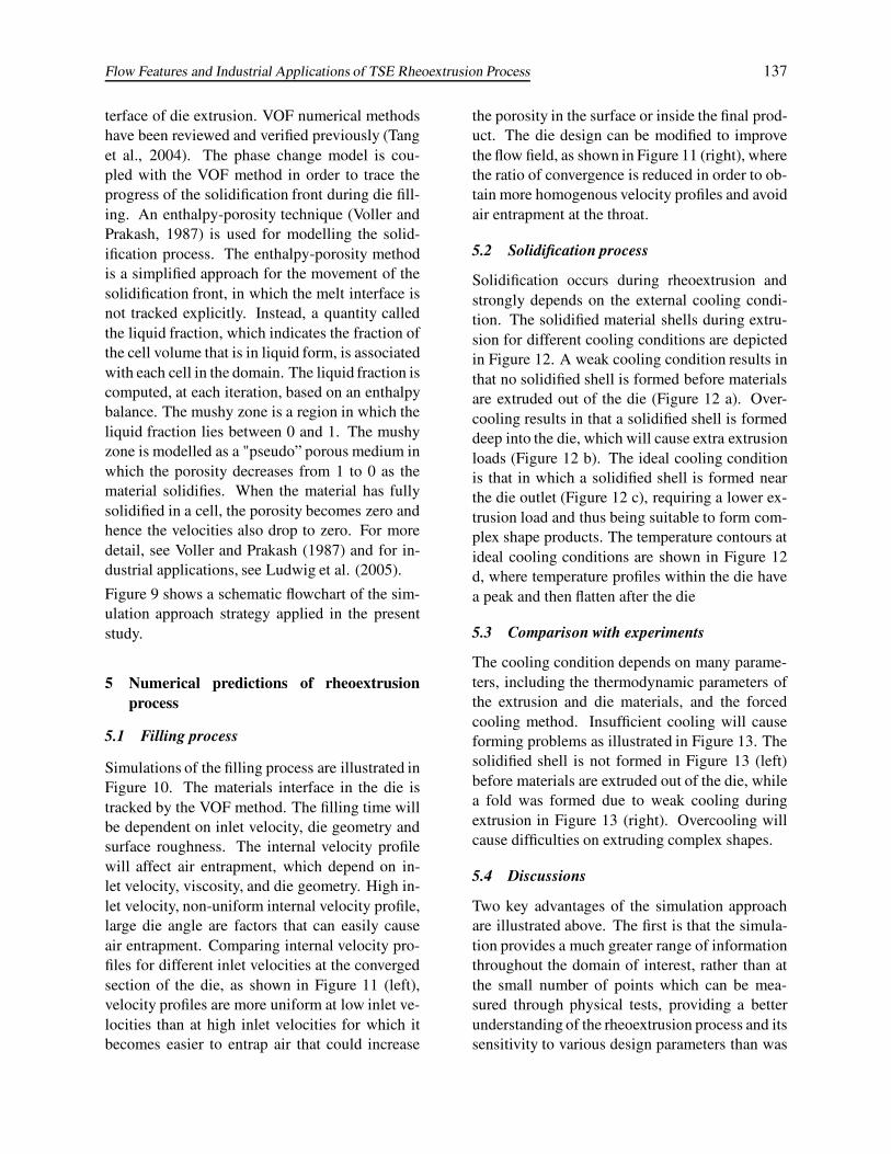
Figure 9: Schematic flowchart of simulation approach strategy
Flow Features and Industrial Applications of TSE Rheoextrusion Process 137
terface of die extrusion. VOF numerical methodshave been reviewed and verified previously (Tanget al., 2004). The phase change model is cou-pled with the VOF method in order to trace theprogress of the solidification front during die fill-ing. An enthalpy-porosity technique (Voller andPrakash, 1987) is used for modelling the solid-ification process. The enthalpy-porosity methodis a simplified approach for the movement of thesolidification front, in which the melt interface isnot tracked explicitly. Instead, a quantity calledthe liquid fraction, which indicates the fraction ofthe cell volume that is in liquid form, is associatedwith each cell in the domain. The liquid fraction iscomputed, at each iteration, based on an enthalpybalance. The mushy zone is a region in which theliquid fraction lies between 0 and 1. The mushyzone is modelled as a "pseudo” porous medium inwhich the porosity decreases from 1 to 0 as thematerial solidifies. When the material has fullysolidified in a cell, the porosity becomes zero andhence the velocities also drop to zero. For moredetail, see Voller and Prakash (1987) and for in-dustrial applications, see Ludwig et al. (2005).
Figure 9 shows a schematic flowchart of the sim-ulation approach strategy applied in the presentstudy.
5 Numerical predictions of rheoextrusionprocess
5.1 Filling process
Simulations of the filling process are illustrated inFigure 10. The materials interface in the die istracked by the VOF method. The filling time willbe dependent on inlet velocity, die geometry andsurface roughness. The internal velocity profilewill affect air entrapment, which depend on in-let velocity, viscosity, and die geometry. High in-let velocity, non-uniform internal velocity profile,large die angle are factors that can easily causeair entrapment. Comparing internal velocity pro-files for different inlet velocities at the convergedsection of the die, as shown in Figure 11 (left),velocity profiles are more uniform at low inlet ve-locities than at high inlet velocities for which itbecomes easier to entrap air that could increase
the porosity in the surface or inside the final prod-uct. The die design can be modified to improvethe flow field, as shown in Figure 11 (right), wherethe ratio of convergence is reduced in order to ob-tain more homogenous velocity profiles and avoidair entrapment at the throat.
5.2 Solidification process
Solidification occurs during rheoextrusion andstrongly depends on the external cooling condi-tion. The solidified material shells during extru-sion for different cooling conditions are depictedin Figure 12. A weak cooling condition results inthat no solidified shell is formed before materialsare extruded out of the die (Figure 12 a). Over-cooling results in that a solidified shell is formeddeep into the die, which will cause extra extrusionloads (Figure 12 b). The ideal cooling conditionis that in which a solidified shell is formed nearthe die outlet (Figure 12 c), requiring a lower ex-trusion load and thus being suitable to form com-plex shape products. The temperature contours atideal cooling conditions are shown in Figure 12d, where temperature profiles within the die havea peak and then flatten after the die
5.3 Comparison with experiments
The cooling condition depends on many parame-ters, including the thermodynamic parameters ofthe extrusion and die materials, and the forcedcooling method. Insufficient cooling will causeforming problems as illustrated in Figure 13. Thesolidified shell is not formed in Figure 13 (left)before materials are extruded out of the die, whilea fold was formed due to weak cooling duringextrusion in Figure 13 (right). Overcooling willcause difficulties on extruding complex shapes.
5.4 Discussions
Two key advantages of the simulation approachare illustrated above. The first is that the simula-tion provides a much greater range of informationthroughout the domain of interest, rather than atthe small number of points which can be mea-sured through physical tests, providing a betterunderstanding of the rheoextrusion process and itssensitivity to various design parameters than was

138 Copyright c© 2007 Tech Science Press FDMP, vol.3, no.2, pp.129-146, 2007
Figure 10: Simulation of filling process in die extrusion at different time steps.
Figure 11: Comparison of velocity profiles at converged section of die for different inlet velocities; leftgraph is for low inlet velocity, and right graph is for high inlet velocity. Velocity profiles are more uniformin the left graph, and there is less chance for entrapping air to form porosity.

Flow Features and Industrial Applications of TSE Rheoextrusion Process 139
�
�� ��
����
Figure 12: Comparison of solid fraction contours for different cooling conditions. The solidified shellwas formed for a weak cooling condition (a), strong cooling condition (b), ideal cooling condition (c) andcorresponding temperature contours (d).
ever possible to obtain experimentally. Second,simulation makes it possible to evaluate a largenumber of alternative die designs and process pa-rameters, without the time and expense requiredto actually build and test them.
Results show that the numerical method was ableto simulate the rheological behaviour of SSM al-loy in rheoextrusion process. The rheologicalbehaviour of the filling and solidification phasesin rheoextrusion process was demonstrated, andqualitative agreement of the defect analysis canbe achieved by comparison with experimental re-sults, as shown in Figures 13 and 14. The prelim-inary model can be used to obtain an insight intoextrusion load, cooling rate, temperature distribu-tion and velocity profiles, thus providing a guideto the operating condition of rheoextrusion in or-
der to reduce trial and error experiments for pa-rameter optimisation.
6 Approaches for Industrial Applications
6.1 Analysis of industrial applications
Extrusion of Mg alloys is used to produce long,straight, semi-finished Mg products. Pressureis applied hydraulically by a ram to the backof a heated billet (300–400˚C) and the metal issqueezed through a die into the desired configu-ration. An extrusion pressure of 850 to 900 MPais sufficient for extrusion of most Mg alloys intointricate shapes. During extrusion of Mg shapes,quality and production rate are affected by sev-eral variables, which include the geometry andcomplexity of the shape, the reduction in area,

140 Copyright c© 2007 Tech Science Press FDMP, vol.3, no.2, pp.129-146, 2007
Figure 13: Possible forming problems due to poor cooling. The solidified shell is not formed before mate-rials are extruded out of die (left). A fold was formed due to weak cooling during extrusion-case 1 (right).Numerical simulations are shown on top, experimental results (Fang, 2003) are shown below.
Figure 14: Comparison of numerical simulations and experimental samples (Fang, 2003). The solidifiedshell is not formed before materials extrude out of die (left). A fold was formed due to weak cooling duringextrusion-case 2 (right).

Flow Features and Industrial Applications of TSE Rheoextrusion Process 141
the alloy being used, the temperature at whichthe extrusion is being produced, and the designof the die. With fixed-die design and a given al-loy, extrusion temperature and extrusion rate canbe optimised. In principle, the higher the oper-ating temperature the faster is the extrusion rate.However, the billet temperature is limited by thehot-shortness temperature of the alloy being used.The hot-shortness temperature is defined as thetemperature at which the lowest melting compo-nent in the alloy begins to melt. This molten ma-terial causes the product to tear during extrusion.Frictional forces during the extrusion process willalso lead to overheating and hot shortness. Un-der any circumstances the onset of hot shortnessmust be prevented, as this leads to a direct lossof production. Therefore, the extrusion speed ofmagnesium has to be kept low, in the order of 1to 20 m/min, depending on the type of alloy andthe processing conditions. For comparison, alu-minium extrusion speeds can be as high as 100m/min.
The rheoextrusion process is schematically illus-trated in Figure 15. The rheoextrusion equipmentconsists of a number of twin-screw slurry makers,a slurry accumulator, a rheoextruder and an extru-sion die. The twin-screw slurry makers and theslurry accumulator form the slurry supply system.Liquid Mg alloy is sequentially fed into the slurrymaker whereby it is transformed into high qualitysemi-solid slurry with a designated solid fraction.The semi-solid slurry is then transferred into theslurry accumulator, from which the slurry is fedcontinuously into the rheoextruder for extrusion.Although the twin-screw slurry makers work ina cyclic manner, rheoextrusion is a continuousprocess. By using different extrusion dies, therheoextrusion process can be designed to producerods and slabs for further processing and profileextrusions for direct component construction (seeFigure 16, from Scamans and Fan, 2006a).
The generic characteristics of the rheoformingprocess include low cost, high material yield andfine and uniform microstructure over the entirecross section. It is the fine and uniform overallmicrostructure that makes the rheoformed prod-ucts advantageous as quality feedstock materials
for further solid-state forming, such as extrusion,rolling, forging, wire drawing and conform ex-trusion. Possible design approaches for industrialapplications are shown in Figure 17 (Scamans andFan, 2005b, 2006b).
6.2 Comparison of industrial processes
During the rheoextrusion process, liquid metalis fed into the twin-screw extruder with a con-trolled feeding rate through a liquid metal pumpand cooled and sheared simultaneously to pro-duce the desirable SSM slurry. The SSM slurryis then passed to a gear pump to regulate the ex-trusion pressure and speed. The extrusion die actsas a device for the final solidification and for cre-ating the final profile.
The rheoextrusion process has the following ad-vantages in comparison with conventional hot ex-trusion:
• Lower extrusion pressure(1/10—1/5 of con-ventional hot extrusion)
• Higher extrusion ratio possible
• Longer die life due to low extrusion pressure
• Complex cross-sectional profile
• Fine and uniform microstructure on the ex-trudate cross-section
• Feasible for alloys with poor deformability
• Lower cost
• Higher production rate
Both rheoextrusion and continuous rheocastingare processes designed for the production of con-tinuous products. Table 2 compares the majordifferences between these two processes (Fan,2002).
7 Concluding remarks
This paper presented a numerical investigationand industrial analysis of the rheoextrusion pro-cess. The investigations have revealed a wealth

142 Copyright c© 2007 Tech Science Press FDMP, vol.3, no.2, pp.129-146, 2007
Figure 15: Flowchart of rheoextrusion process for industrial applications
Table 2: Comparison between rheoextrusion and continuous rheocasting processes
Process Rheoextrusion Continuous rheocastingShaping device Extrusion die Water cooled Cu-mouldSuitable solid fraction High (>0.6) Low (<0.3)Cross-section Small, sheet, complex, profile Large, simpleSuitable alloy Wrought, thixo-alloys Cast, rheo-alloysEquipment New Compatible with existing DC casting machineField of application Automotive, consumer goods Thixotropic feedstock, general engineering
of interesting rheological and microstructural fea-tures, providing qualitative and quantitative in-sights into the rheoextrusion process which areconsistent with experimental work. A practicalprocess was discussed and a possible arrangementwas designed for industrial applications based ona successful prototype experimental device, sincethe creation of desirable SSM slurry is crucial tothe quality of production and maintenance of themicrostructure. Volume fraction of the semi-solidslurry was significant to the success of the rheoex-trusion process and found to be a quantifiable pa-
rameter to desirable slurry. Continuation of tri-als to improve the understanding of the rheologyand mechanical properties created by the rheoex-trusion process is the natural step from this earlydevelopment work, which was patented for fur-ther commercial applications. The potential re-duction in both process cost and complexity overthat of traditional techniques is an incentive to in-dustrial application. The ability of rheoextrusionto produce high tolerance, complex profiles andnet-shaped products leaves the process well suitedto many industrial tasks.

Flow Features and Industrial Applications of TSE Rheoextrusion Process 143
Figure 16: Schematic illustration of arrangement for rheoextrusion device (Scamans and Fan, 2006a)
Figure 17: Conceptual designs of industrial applications of DC-rheoextrusion (left) and twin-roll rheoextru-sion (right) (Scamans and Fan, 2005b, 2006b)

144 Copyright c© 2007 Tech Science Press FDMP, vol.3, no.2, pp.129-146, 2007
Acknowledgement: The authors would like toacknowledge support from the School of Engi-neering and Design and the Brunel Centre forAdvanced Solidification Technology (BCAST)at Brunel University, UK, and the Departmentof Mechanical and Manufacturing Engineering,RMIT University, Australia as well as College ofEnergy and Power Engineering, Nanjing Univer-sity of Aeronautics and Astronautics, China. Weare also grateful to researchers in their numericaland experimental groups for helpful discussionson numerical approaches and experimental pro-cesses.
References
Abhilash E.; Joseph M. A.; Krishna P. (2006):Prediction of dendritic parameters and macrohardness variation in permanent mould casting ofAl-12%Si alloys using artificial neural networks.Fluid Dynamics & Materials Processing, vol. 2,pp. 211-220.
Alkorta, J.; Rombouts, M.; Messemaeker, J.D.; Froyen, L.; Sevillano, J. G. (2002): On theimpossibility of multi-pass equal-channel angulardrawing. Scripta Materialia, vol. 47, pp.13-18.
Amberg, G.; Shiomi, J. (2005): Thermocapil-lary flow and phase change in some widespreadmaterials processes. Fluid Dynamics & MaterialsProcessing, vol. 1, pp. 81-95.
Antúnez, H. J. (2000): Linear elements formetal-forming problems within the flow ap-proach. Computer Methods in Applied Mechanicsand Engineering, vol. 190, pp. 783-801.
Aydin, I.; Biglari F. R.; Briscoe B. J.; LawrenceC. J.; Adams M. J. (2000): Physical and numeri-cal modelling of ram extrusion of paste materials:conical die entry case. Computational MaterialsScience, vol. 18, pp. 141-155.
BEMflow, http://www.madisongroup.com/Pro-ducts/Bemflow/bemflow.html#Advantages
Bjork, T.; Bergstrom, J.; Hogmark, S. (1999):Tribological simulation of aluminium hot extru-sion. Wear, vol. 224, pp. 216-225.
Carneiro, O. S.; Nóbrega, J. M.; Pinho, F. T.;Oliveira, P. J. (2001): Computer aided rheolog-
ical design of extrusion dies for profiles. Jour-nal of Materials Processing Technology, vol. 114,pp.75-86.
Celik, K. F.; Chitkara, N. R. (2002): Extru-sion of non-symmetric U- and I-shaped sectionsthrough ruled-surface dies: numerical simulationsand some experiments. International Journal ofMechanical Sciences, vol. 44, pp. 217-246.
Elsey, J.; Riepenhausen, J.; McKay, B.; Bar-ton, G. W.; Willis, M. (1999): Modeling andcontrol of a food extrusion process. Computers& Chemical Engineering, vol. 21, Suppl. 1, pp.S361-S366.
Fan, Z.; Bevis, M. J.; Ji, S. (1999): Process andapparatus for manufacturing casting from immis-cible metallic liquids, Patent PCT/WO 01/23124A1.
Fan, Z.; Ji, S.; Zhang, J. (2001): Processingof immiscible metallic alloys by rheomixing pro-cess. Materials Science and Technology, vol. 17,pp. 838-842.
Fan, Z. (2002): Twin-screw rheoforming tech-nologies for semisolid processing of Mg-alloys.Proceeding of the 7th International Conferenceon Semi-solid Processing of Alloys and Compos-ites, Tsukuba, Japan.
Fang, X. (2003): Twin-screw rheoextrusion ofSn-15wt%Pb alloys, Internal Report, BCAST,Brunel University, UK.
Gejadze, I.; Jarny, Y. (2002): An inverse heattransfer problem for restoring the temperaturefield in a polymer melt flow through a narrowchannel. International Journal of Thermal Sci-ences, vol. 41, pp. 528-535.
Hao, N.; Li, K. (2000): Numerical design of thedie land for shape extrusion. Journal of MaterialsProcessing Technology, vol. 101, pp. 81-84.
Hong C.P., Zhu M.F. and Lee S.Y., (2006),Modeling of Dendritic Growth in Alloy Solidifi-cation with Melt Convection, FDMP: Fluid Dy-namics & Materials Processing, Vol. 2, No. 4,pp. 247-260
Hu, Z.; Zhu, L.; Wang, B.; Liu, Z.; Miao,Y.; Xie, P.; Gu S.; Sheng, W. (2000): Com-puter simulation of the deep extrusion of a thin-

Flow Features and Industrial Applications of TSE Rheoextrusion Process 145
walled cup using the thermo-mechanically cou-pled elasto-plastic FEM. Journal of MaterialsProcessing Technology, vol. 102, pp. 128-137.
Hultgren, R.; Orr, R. L.; Anderson, P. D.; Kel-ley, K. K. (1973): Selected Values of the Thermo-dynamic Properties of Binary Alloys, ASM: Met-als Park.
Hwang, J.-H.; Ko, D.-C.; Min, G.-S.; Kim, B.-M.; Choi, J.-C. (2000): Finite element simula-tion and experiment for extrusion of semi-solid Al2024. International Journal of Machine Tools andManufacture, vol. 40, pp.1311-1328.
Iida, T.; Guthrie, R. I. L. (1988): The PhysicalProperties of Liquid Metals, New York: OxfordUniversity Press.
Kang, C. G.; Jung, Y. J.; Kwon, H. C. (2002):Finite element simulation of die design for hot ex-trusion process of Al/Cu clad composite and itsexperimental investigation. Journal of MaterialsProcessing Technology, vol. 124, pp. 49-56.
Kopp, R.; Moller, T.; Neudenberger, D.;Winning, G. (1999): Thixoforging andthixoextrusion-benefits of innovative formingtechnologies. Proc. 6th International Conferenceon Technology of Plasticity (ICTP),Nuremberg,Germany, vol.3, pp.1677-1682.
Langkruis, J. van de; Lof, J.; Kool, W. H.;Zwaag, S. van der; Huétink, J. (2000): Com-parison of experimental AA6063 extrusion tri-als to 3D numerical simulations, using a generalsolute-dependent constitutive model. Computa-tional Materials Science, vol. 18, pp. 381-392.
Langseth, M.; Hopperstad O. S.; Berstad, T.(1999): Crashworthiness of aluminium extru-sions: validation of numerical simulation, effectof mass ratio and impact velocity. InternationalJournal of Impact Engineering, vol. 22, pp. 829-854.
Lee, G.-A.; Im,Y.-T. (1999): Finite-element in-vestigation of the wear and elastic deformation ofdies in metal forming. Journal of Materials Pro-cessing Technology, vol. 89-90, pp. 123-127.
Lee, S. K.; Ko, D. C.; Kim, B. M. (2000): Op-timal die profile design for uniform microstruc-ture in hot extruded product. International Jour-nal of Machine Tools and Manufacture, vol. 40,
pp. 1457-1478.
Lee, B. K.; Kwon, H. H.; Cho,H. Y. (2002): Astudy on the automated process planning systemfor cold forging of non-axisymmetric parts usingFVM simulation. Journal of Materials Process-ing Technology, vol. 130-131, pp. 524-531.
Li, B. Q. (1997): Numerical simulation of flowand temperature evolution during the initial phaseof steady-state solidification, Journal of MaterialsProcessing Technology, vol.17, pp. 402-413.
Li, C-H. (1999): Modelling extrusion cooking,Food and Bioproducts Processing, vol. 77, pp.55-63.
Lin S. Y.; Lin, F. C. (2003): Prediction of folddefect in barreling formations of cylinder upset-ting. Finite Elements in Analysis and Design, vol.39, pp. 325-341.
Liu, Z. Y.; Wang, Z.; Wang, E. (1999): Fi-nite element simulation of the stress distributionof equal-cross section lateral extrusion. MaterialsScience and Engineering A, vol. 262, pp. 137-140.
Lof, J.; Blokhuis, Y. (2002): FEM simulations ofthe extrusion of complex thin-walled aluminiumsections. Journal of Materials Processing Tech-nology, vol. 122, pp. 344-354.
Lof, J. (2001): Elasto-viscoplastic FEM simula-tions of the aluminium flow in the bearing areafor extrusion of thin-walled sections. Journal ofMaterials Processing Technology, vol. 114, pp.174-183.
Ludwig, A.; Gruber-Pretzler, M.; Wu, M.;Kuhn, A.; Riedle, J. (2005): About the forma-tion of macrosegregations during continuous cast-ing of Sn-Bronze. Fluid Dynamics & MaterialsProcessing, vol. 1, pp. 285-300.
MacCormack, C.; Monaghan, J. (2002): 2Dand 3D finite element analysis of a three stageforging sequence. Journal of Materials Process-ing Technology, vol. 127, pp. 48-56.
Mehta, B. V.; Al-Zkeri, I.; Gunasekera J. S.;Buijk, A. (2000): Evaluation of MSC SuperForgefor 3D simulation of streamlined and shear ex-trusion dies, Proceedings of the 2nd InternationalAutomotive Conference, Dearborn, MI.

146 Copyright c© 2007 Tech Science Press FDMP, vol.3, no.2, pp.129-146, 2007
Mehta, B. V.; Al-Zkeri, I.; Gunasekera J. S.;Buijk, A. (2001): 3D flow analysis inside shearand streamlined extrusion dies for feeder plate de-sign. Journal of Materials Processing Technol-ogy, vol. 113, pp. 93-97.
Narski J. and Picasso M., (2007), Adaptive 3Dfinite elements with high aspect ratio for dendriticgrowth of a binary alloy including fluid flow in-duced by shrinkage, FDMP: Fluid Dynamics &Materials Processing, Vol. 3, No. 1, pp. 49-64
Ogawa, N.; Shiomi, M.; Osakada, K. (2002):Forming limit of magnesium alloy at elevatedtemperatures for precision forging. InternationalJournal of Machine Tools and Manufacture, Vol.42, pp.607-614.
Okstad, K. M.; Kvamsdal, T.; Abtahi, S.(2000): A coupled meat and flow solver for ex-trusion simulation. European Congress on Com-putational Methods in Applied Science and Engi-neering, ECCOMAS 2000, Barcelona.
Perez, M.; Barbé, J.-C.; Neda, Z.; Bréchet, Y.;Salvo, L. (2000): Computer simulation of the mi-crostructure and rheology of semi-solid alloys un-der shear. Acta Materialia, vol. 48, pp. 3773-3782.
Polyflow (2002): Extrusion, presen-tation at Polyflow s.a., Louvain-la-Neuve, Belgium. http://www.polyflow.be/,http://www.fluent.com/software/index.htm
Raj, K. H.; Sharma, R. S.; Srivastava, S.; Pat-vardhan, C. (2000): Modeling of manufacturingprocesses with ANNs for intelligent manufactur-ing. International Journal of Machine Tools andManufacture, vol. 40, pp. 851-868.
Reyes, A.; Langseth, M.; Hopperstad, O. S.(2002): Crashworthiness of aluminium extrusionssubjected to oblique loading: experiments and nu-merical analyses. International Journal of Me-chanical Sciences, vol. 44, pp. 1965-1984.
Roberts, K. A.; Fang, X.; Ji, S.; Fan, Z. (2002):Development of twin-screw rheoextrusion pro-cess. Proceeding of the 7th International Confer-ence on Semi-solid Processing of Alloys and Com-posites, Tsukuba, Japan.
Rosochowski, A.; Olejnik, L. (2002): Numericaland physical modelling of plastic deformation in
2-turn equal channel angular extrusion. Journal ofMaterials Processing Technology, vol. 125-126,pp. 309-316.
Scamans, G.M.; Fan, Z. (2005a): Twin roll rheo-casting of Aluminium alloys, Light Metal Age,vol. 63, pp 6-9.
Scamans, G.M.; Fan, Z. (2005b): Rheoformingof novel Aluminium and Magnesium alloys, Alu-minium Inter. Today. vol.17, pp 22-26.
Scamans, G.M.; Fan, Z. (2006a): High shearrheocasting of Aluminium alloys, APT Alu-minium - Process & Product Technology, Alu-minium, Special Edition, pp 54-57.
Scamans, G.M.; Fan, Z. (2006b): Cost andstrength competitive Aluminium alloys for auto-motive applications, SAE/UK Vehicle TechnologyMagazine, in press.
Skauvik (1999): Computer simulation improvesquality and reduces cost of aluminium extrusions.JA094, Fluent Inc, USA.
Tang, H.; Wrobel, L. C.; Fan, Z. (2004): Tack-ing of immiscible interfaces in multiple-materialmixing process. Computational Materials Sci-ence, vol. 29, pp. 103-118.
Voller, V. R.; Prakash, C. (1987): A fixed-gridnumerical modeling methodology for convection-diffusion mushy region phase-change problems.International Journal of Heat and Mass Transfer,vol. 30, pp. 1709-1720.
Vollertsen, F.; Sprenger, A.; Kraus, J.; ArnetH. (1999): Extrusion, channel, and profile bend-ing: a review. Journal of Materials ProcessingTechnology, vol. 87, pp. 1-27.
Ward, P. J.; Atkinson, H. V.; Kirkwood, D.H.; Liu, T. Y. (2000): Issues in the valida-tion of CFD modelling of semi-solid metal form-ing. Mathematical Modelling in Metals Process-ing and Manufacturing– COM 2000, Ottawa, On-tario, Canada.
Yoon, J.-H.; Im, Y.-T.; Kim, N.-S. (1999):Rigid–thermoviscoplastic finite-element analysisof the semi-solid forging of Al2024. Journal ofMaterials Processing Technology, vol. 89-90, pp.104-110.