flow in pipe networks - dcu.ie · at least once each month, check that the elcb is operating...
TRANSCRIPT

~~
FLOW IN PIPE NETWORKS
nC11
I
CI-';
~
ISSUE 11
DECEMBER 1999

n
ARMFIELD LIMITED
OPERATING INSTRUCTIONS AND EXPERIMENTS
C11 - FLOW IN PIPE NETWORKS
PAGE NO.
1SAFETY
5INTRODUCnON
g 6RECEIPT OF EQUIPMENT
~ 8DESCRlPnON
~
11INST ALLA nON REQUIREMENTS
12ASSE:rvIBLY
13CONNEcnON TO SERVICES
14CO~SSIONINGI21ROUTINE MAINTENANCE
22INDEX TO EXPERIMENTS
aGENERAL SAFETY
I

SAFETY IN THE USE OF EQUIPMENT SUPPLIED BY ARMFIELD
Before proceeding to install, commission or operate the equipment described in thisinstruction manual we wish to alert you to potential hazards so that they may be avoided.
Although designed for safe operation, any laboratory equipment may involve processes orprocedures which are potentially hazardous. The major potential hazards associated withthis particular equipment are listed below.
INJURY nlROUGH MISUSE.
INJURY FROM ELECTRIC SHOCK
INJURY FROM INCORRECT HANDLING.
POISONING FROM TOXIC MA1ERIALS (E.G. MERCURY).
RISK OF INFEcnON THROUGH LACK OF CLEANLINESS
Accidents can be avoided provided that equipment is regularly maintained and staffand students are made aware of potential hazards. A list of general safety rules isincluded in this manual, to assist staff and students in this regard. The list is not intendedto be fully comprehensive but for guidance only.
Please refer to the notes overleaf regarding the Control of Substances Hazardous toHealth Regulations.

The COSHH Regulations
The Control of Substances Hazardous to Health Regulations (1988)
The COSIffi regulations impose a duty on employers to protect employees and othersfrom substances used at work which may be hazardous to health. The regulations requireyou to make an assessment of all operations which are liable to expose any person tohazardous solids, liquids, dusts, vapours, gases or micro-organisms. You are also requiredto introduce suitable procedures for handling these substances and keep appropriaterecords.
Since the equipment supplied by Armfield Limited may involve the use of substanceswhich can be hazardous (for example, cleaning fluids used for maintenance or chemicalsused for particular demonstrations) it is essential that the laboratory supervisor or someother person in authority is responsible for implementing the COSlllI regulations.
Part of the above regulations are to ensure that the relevant Health and Safety Data Sheetsare available for all hazardous substances used in the laboratory. Any person using ahazardous substance must be informed of the following:
Physical data about the substanceAny hazard from fire or explosionAny hazard to healthAppropriate First Aid treatmentAny hazard from reaction with other substancesHow to clean/dispose of spillageAppropriate protective measuresAppropriate storage and handling
Although these regulations may not be applicable in your country, it is stronglyrecommended that a similar approach is adopted for the protection of the studentsoperating the equipment. Local regulations must also be considered.
Water-Borne InfectionsThe equipment described in this instruction manual involves the use of water which undercertain conditions can create a health hazard due to infection by hanDful micro-
organisms.
For example, the microscopic bacterium called Legionella pneumophila will feed on anyscale, rust, algae or sludge in water and will breed rapidly if the temperature of water isbetween 20 and 45°C. Any water containing this bacterium which is sprayed or splashedcreating air-borne droplets can produce a form of pneumonia called Legionnaires Diseasewhich is potentially fatal.
2

Legionella is not the only harmful micro-organism which can infect water, but it serves asa useful example of the need for cleanliness.
Under the COSmI regulations, the following precautions must be observed:-
Any water contained within the product must not be allowed to stagnate, i.e. the watermust be changed regularly.
Any rust, sludge, scale or algae on which micro-organisms can feed must be removedregularly, i.e. the equipment must be cleaned regularly.
Where practicable the water should be maintained at a temperature below 20°C or above45°C. If this is not practicable then the water should be disinfected if it is safe andappropriate to do so. Note that other hazards may exist in the handling of biocides used todisinfect the water.
A scheme should be prepared for preventing or controlling the risk incorporating all ofthe actions listed above.
Further details on preventing infection are contained in the publication "The Control ofLegionellosis including Legionnaires Disease" - Health and Safety Series booklet HS (G)70.
3

USE OF EARTH LEAKAGE CIRCUIT BREAKER AS AN ELECTRICALSAFETY DEVICE
The equipment described in this Instruction Manual operates from a mains voltageelectrical supply. The equipment is designed and manufactured in accordance withappropriate regulations relating to the use of electricity. Similarly, it is assumed thatregulations applying to the operation of electrical equipment are observed by the end user.
However, to give increased operator protection, Annfield Ltd have incorporated an EarthLeakage Circuit Breaker (ELCB, alternatively called a Residual Current Circuit Breakeror RCCB) as an integral part of this equipment. If through misuse or accident theequipment becomes electrically dangerous, an ELCB will switch off the electrical supplyand reduce the severity of any electric shock received by an operator to a level which,under normal circumstances, will not cause injury to that person.
At least once each month, check that the ELCB is operating correctly by pressing theTEST button. The circuit breaker MUST trip when the button is pressed. Failure to tripmeans that the operator is not protected and the equipment must be checked and repairedby a competent electrician before it is used.
4

INTRODUCTION
A common problem in pipeline hydraulics is the determination of the pressures and flowsin a system of interconnected pipes, often known as a "pipe network". Such networksrange from a single pipe to complex systems involving many pipes of different lengthsand diameters, and incorporating distributed off-tube and supply points. A town watersupply is a good example of a very complex network. A good understanding of thebehaviour of pipe networks and the ability to predict flow and pressure distributions areessential in the design of systems for the transportation of fluids. The Armfield Flow inPipe Networks is specifically designed to allow the setting up of a wide range of pipearrays and the measurement of the flows and pressures using water as the fluid.
5

RECEIPT OF EQUIPMENT
1. SALES .IN THE UNfl'ED KINGDOM
The apparatus should be carefully unpacked and the components checked againstthe Advice Note. A copy of the Advice Note is supplied with this instructionmanual for reference.
Any omissions or breakages should be notified to Armfield Limited within threedays of receipt.
2. SALES OVERSEAS
The apparatus should be carefully unpacked and the components checked againstthe Advice Note. A copy of the Advice Note is supplied with this instructionmanual for reference.
Any omissions or breakages should be notified immediately to the InsuranceAgent stated on the msurance Certificate if the goods were insured by AnnfieldLimited.
Your own insurers should be notified immediately if insurance was arranged byyourselves.
'I; :,
I 'f,
~
6
~

DESCRIPTION
The water supply and measurement module is based on the Annfield hydraulics benchwhich is proven as a service facility.
The bench comprises of upper and lower G.R.P. mouldings in contrasting colours,designed for durability and freedom from maintenance. The lower moulding incorporatesa water storage sump tank from which a self-priming centrifugal pump delivers water tothe system under examination. The upper moulding incorporates a volumetric measuringtank which is stepped to allow the measurement of both high and low flow rates, thewater level being indicated by a remote sight tube and scale on the bench front. A stillingbaflle reduces disturbance in the volumetric tank and a dump valve in the base returns themeasured water to the sump tank for recycling.
The top of the bench is fitted with a metal supporting frame for the pipe networks and forthe inlet manifold which is common to any selected system. Five pipe lengths in threediameters are supplied; and a wide range of series, parallel and mixed configurations ispossible using the interconnecting fittings, also supplied. Fittings are readily assembledwith screwed couplings sealed with O-rings. Pressure differences between points in thesystem are measured with 'u' tube manometers; water for the lower differences andmercury for the higher. Self sealing pressure tapping points are provided in the fittings towhich connection is made via probes and flexible tubes.
Air in the manometer connecting tubes is automatically bled from stopcocks used to shutoff the manometers. The interchangeable length of pipe and interconnecting fittings arestored on a board attached to one end of the bench.
NOTE:
To connect a test probe to a pressme point, simply push the tip of the test probe into thepressme point until it latches. To disconnect a test probe from a pressme point, press themetal clip on the side of the pressme point to release the test probe. Both test probe andpressme point will seal to prevent loss of water.
8
~
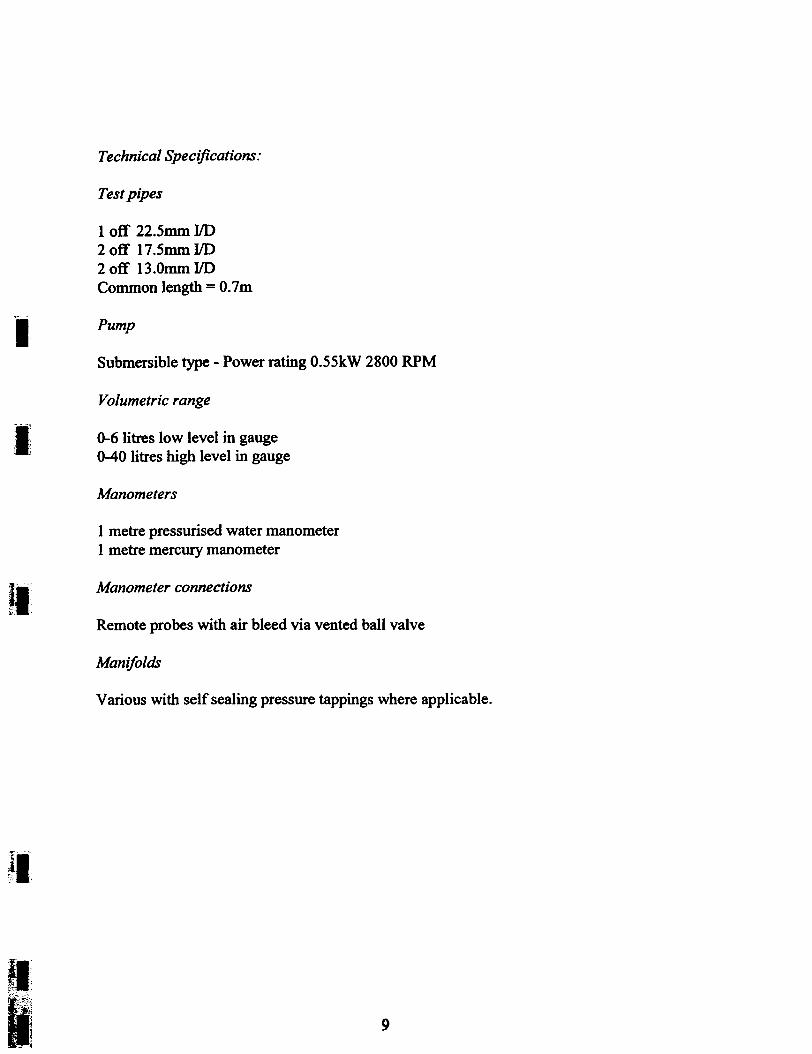
Technical Specifications:
Test pipes
1 off 22.5mm I/D2 off 11.5mm I/D2 off 13.0mm I/DCommon length = O.1m
'1Pump
Submersible type - Power rating 0.55kW 2800 RPM
Vo/umetric range
.I 0-6 litres low level in gauge0-40 litres high level in gauge
~
Manometers
1 metre pressurised water manometer1 metre mercury manometer
~
Manometer connectionsI.~\
Remote probes with air bleed via vented ball valve
Manifolds
Various with self sealing pressure tappings where applicable.
.11"f:
If :I";;~' Tf'~
9

Use of the mercury manometer
A mercury manometer is supplied with this product to facilitate measurement ofdifferential pressures in the system using a fundamental technique that provides accuratereadings without the need for reference calibration.
The design of the manometer ensures that once primed, the mercury is submerged belowwater preventing the escape of harmful vapour. Catch pots at the rear of the manometerprevent the escape of mercury should the measuring range of the manometer be exceeded.
Annfield can supply a portable digital pressure meter that can be connected in place ofthe mercury manometer when local regulations do not allow the use of mercury.
The product code for this meter is H12-8 and it is also available with a NPL 5 pointcalibration certificate (H12-8-CC1) or NAMAS 10 point calibration certificate (H12-8-CC2) if required.
10

INSTALLATION REQUIREMENTS
ELECTROMAGNEllC CaMP A TIBILffY
This apparatus is classified as Education and Training Equipment under theElectromagnetic Compatibility (Amendment) Regulations 1994. Use of the apparatusoutside the classroom, laboratory or similar such place invalidates confonnity with theprotection requirements of the Electromagnetic Compatibility Directive (89/336/EEC)and could lead to prosecution.
FACnmES REQUIRED
The equipment is designed for floor standing in a static location and requires a finn levelfloor.
The equipment requires connection to a single phase, fused electrical supply. Four metresof supply cable is supplied with the equipment.
Installation can be carried out using a basic tool kit.
Overall dimensions of the equipment are:
HEIGHTLENGlHwmlH
1.3mO.78m2.Om
It is a self-contained unit and needs only a temporary supply of cold water for initial
filling.
1

ASSEMBLY
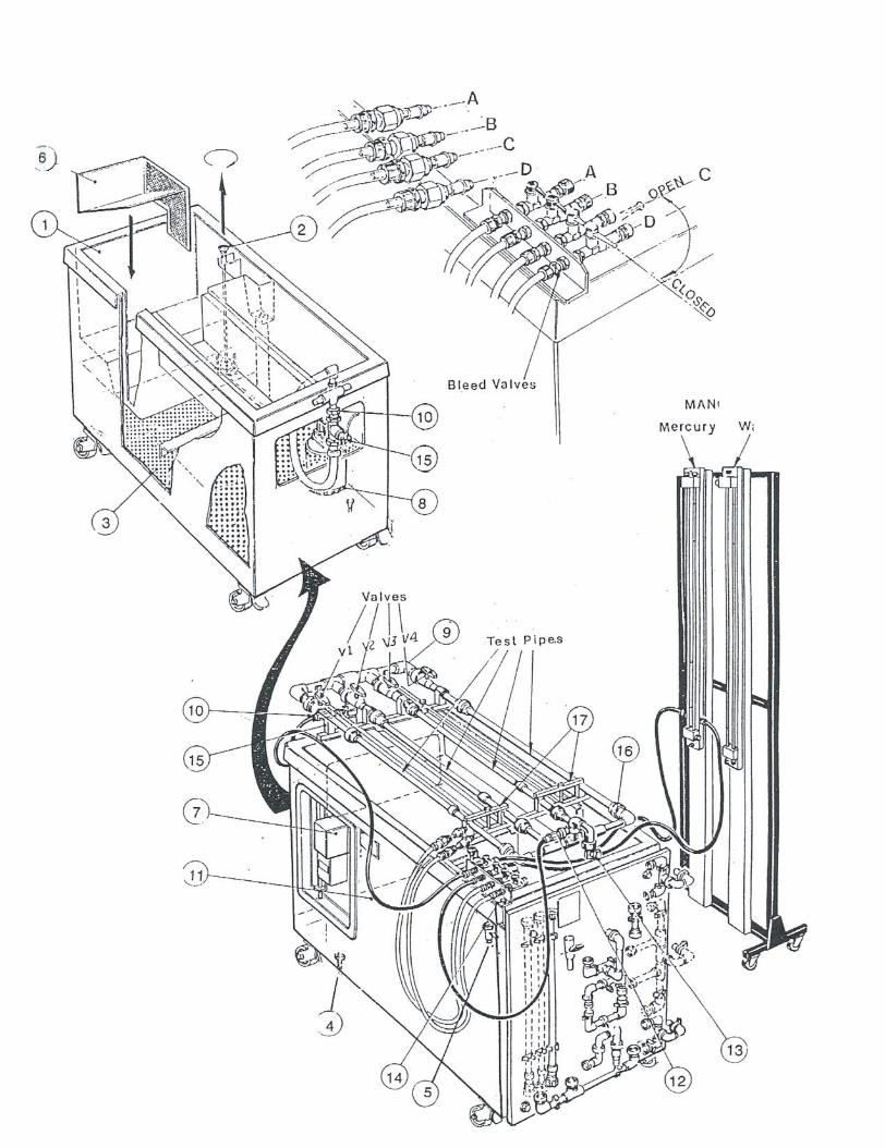
All numerical references refer to the diagram on page 16.
Clamp the pipe network support frame (15) to the top of the bench with the fourlong clamping bolts.
2. Attach the angle bracket (14) which carries the air bleed valves to the bench withthe remaining clamping bolt, and to the pipe network support frame (15) with theM4 x 15mm long bolt.
Place the inlet manifold frame (9) onto the pipe network support frame and clipinto position.
3
4. Connect inlet manifold (9) to pump using the flexible tubing provided.
s. Connect the four straight test pipes to the inlet manifold and clamp the tubes intoposition using the clamps (17)
6. Connect the outlet manifold (16) to the test pipes with the discharge tube in thevolumetric tank. Ensure that all couplings between the manifolds and test pipesare tightened.
Assembly of Manometers
1 Clamp the base support stand to the main frame with the bolts provided.
2. Clamp the two manometers to the main frame with the mercury manometer on theleft hand side of the frame.
NOTE: There are 2 spacers for the water manometer but only I for the topof the mercury manometer.
Connections between the manometers, the air bleed valves on the bench top, and thepressure test probes should be effected using the flexible tubing provided in accordancewith the manometer connection diagram on page 19.
When positioning the manometer stand take care not to over-stretch the flexible length oftubes when you connect them to the module and the manometers.
12

CONNECTION TO SERVICES
ELECTRICAL SUPPLY FOR VERSION CII-A:
The equipment requires connection to a single phase, fused electrical supply. Thestandard electrical supply for this equipment is 220/240V, 50Hz. Check that the voltageand frequency of the electrical supply agree with the label attached to the supply cable onthe equipment. Connection should be made to the supply cable as follows:-
GREEN/YELLOWBROWNBLUEFuse Rating
EARnILIVE (HOT)NEUTRAL13 AMP
ELECTRICAL SUPPLY FOR VERSIONCII-B;
The equipment requires connection to a single phase, fused electrical supply. Thestandard electrical supply for this equipment is 120V, 50Hz. Check that the voltage andfrequency of the electrical supply agree with the label attached to the supply cable on theequipment. Connection should be made to the supply cable as follows:-
EARnILNE (HOT)NEUTRAL25 AMP
GREEN/YELLOWBROWNBLUEFuse Rating
COLD WATER
The equipment is self-contained and does not require permanent connection to a watersupply. An initial supply of cold water will be required to fill the sump tank. Water willalso be required for cleaning/flushing after use.
DRAIN (COLD WATER)The equipment is self-contained and does not require a drain for nonnal operation. Adrain will be required for cleaning/flushing purposes.
13

COMMISSIONING
All numerical references refer to the drawing on page 19.
Close the drain valve (4) in the base of the sump tank. Place the water supply hoseinto the volumetric tank (1), lift the dump valve (2) with a twist motion of 90°,this will hold the valve in the open position.
1.
Turn on the water and fill the sump tank (3) via the volumetric tank. When fullensure that the water level in the swnp tank is below the outlet in the bottom ofthe volumetric tank.
2.
Turn off the water at the supply, open drain valve (4) and empty the sump, this isto remove any particles of foreign matter residing in the tank. Close the drainvalve and refill the sump tank. Turn off the water and remove the hose.
3.
Place the stilling baft1e (6) into the volumetric tank ensuring that the upper edgeof the baft1e is in line with the exit of the open channel.
4.
s. Connect the electrical supply to the bench.
Check the operation of the RCD by pressing the Test button (refer to page 4). TheRCD must trip when the Test button is pressed. Reset the RCD.
6.
Switch on starter (7) and check that pump (8) is operating satisfactorily, and thatwater is reaching the inlet manifold (9) from the sump tank. Switch off.
7.
Connect all the test pipes into their positions as shown on page 19. Open valvesVI, V2, V3 and V 4 respectively and observe discharge into volumetric tank ofeach valve in turn, with valve (13) open.
8.
Check for leaks.9.
NOTE: To connect a test probe to a pressure point, simply push the tip of the testprobe into the pressure point Wltil it latches. To disconnect a test probefrom a pressure point, press the metal clip on the side of the pressure pointto release the test probe. Both test probe and pressure point will seal toprevent loss of water.
14

Commissioning of the pressurised water manometer and mercury manometer can only becarried out after the general commissioning of the equipment has been completed(described on page 14).
Commissioning the Pressurised Water Manometer
Please refer to the Manometer Connection Diagram on page 19 for the nomenclatureused in this text.
Connect probe C to the pressure tapping (10) on the upstream (inlet) manifold.
Connect probe D to the pressure tapping (12) on the downstream (outlet) manifold.
Close bleed valves C and D on the top of the volumetric tank (handle at 90° to valvebody).
Open isolating valves VI, V2, V3 and V 4 on the test pipes. Open the outlet flow controlvalve (13) below the outlet manifold. Close the inlet flow control valve located below theinlet manifold.
Start the pump then gradually open the inlet flow control valve to allow water to flowthrough the test pipes and into the volumetric tank. Partially close the outlet flow controlvalve to reduce the water flow slightly and pressurise the system. Water will dischargeinto the volumetric tank through a vent hole on the underside of each bleed valve thuspurging air from the flexible tubing to the test probes.
To prime the manometer with water, undo coupling D (connected to the downstreamtapping) on the manometer side of the bleed valve bracket and place the free end of thetubing from the manometer in the volumetric tank. Open bleed valve C and allow waterto flow from the upstream tapping, through the manometer and into the volumetric tank.When all air bubbles have been purged from the manometer close bleed valve C thenreconnect the tubing to coupling D.
Note: To ensure that the manometer remains fully primed ensure that both bleed valvesare closed before disconnecting either probe from the pressure tappings. The bleedvalves should not be opened again until both probes are connected to appropriatepressure tappings.
The manometer can be operated using the following sequence:
Close both bleed valves (C and D) so that water discharges from each bleed valve into thevolumetric tank.
Disconnect each probe from its original pressure tapping by pressing the metal clip on theside of the pressure tapping.
15

Reconnect both probes to the required pressme tappings on the equipment by pushing thetip of the probe into the tapping until it latches. Water will automatically discharge fromthe vent on each bleed valve.
Wait until all air has been purged from the flexible tubing, indicated by a steady flow ofwater from each valve.
Open both bleed valves (C and D). Allow the reading on the manometer to stabilise thenrecord the level of the water (bottom of the meniscus) in each manometer tube.
Close both bleed valves (C and D) after taking the reading. Steps b), c), d) and e) shouldbe repeated as required to eliminate air from the manometer and flexible tubing whiletaking measurements.
The water manometer can be pressurised to allow small differential pressures to bemeasured when static pressure at the tappings is high or low. This condition is indicatedby the level in both tubes being at the top or bottom respectively.
If the water level in both tubes is at the top then the system pressure is high and themanometer must be pressurlsed to bring the levels to mid range on the manometer.Remove the cap from the Schrader connection on the bottom manifold block and connectthe hand pump. Pump slowly until both water levels are on the scale, preferablyequidistant from mid position to allow different pressures to be measured withoutpressurlsing the manometer again. Before taking readings disconnect the hand pump toprevent changes to the levels due to leakage of air.
If the water level in both tubes is at the bottom then the system pressure is low and themanometer must be de-pressurised to bring the levels to mid range on the manometer.Carefully open the bleed screw on the top manifold block to allow air to enter themanometer until the water levels are central on the scale. Ensure that the bleed screw istightened to prevent leakage.
If water flows continuously through the manometer and a stable level cannot be achievedin both tubes then it is likely that the differential pressure exceeds the range of themanometer. It will be necessary to connect the mercury manometer in place of the watermanometer to measure this pressure difference.
16

Commissioning the Mercury Manometer
To ensure safe and accurate operation of the mercury manometer the following primingprocedure should be adopted.
Please refer to the Manometer Connection Diagram on page 19 for the nomenclatureused in this text.
Connect probe A to the pressure tapping (10) on the upstream (inlet) manifold.
Connect probe B to the pressure tapping (12) on the downstream (outlet) manifold.
Close bleed valves A and B on the top of the volumetric tank (handle at 900 to valve
body).
Open isolating valves VI, V2, V3 and V4 on the test pipes. Open the outlet flow controlvalve (13) below the outlet manifold. Close the inlet flow control valve located below theinlet manifold.
Start the pump then gradually open the inlet flow control valve to allow water to flowthrough the test pipes and into the volumetric tank. Partially close the outlet flow controlvalve to reduce the water flow slightly and pressurise the system. Water will dischargeinto the volumetric tank through a vent hole on the underside of each bleed valve thuspurging air from the flexible tubing to the test probes.
Before filling the manometer with mercury it will be necessary to prime the manometerwith water. Undo coupling B (connected to the downstream tapping) on the manometerside of the bleed valve bracket and place the free end of the tubing from the manometer inthe volumetric tank. Open bleed valve A and allow water to flow from the upstreamtapping, through the manometer and into the volumetric tank.
Partially unscrew the fitting at the top of each catch pot (at the rear of the manometer) toallow any trapped air to escape. Ensure that the fittings are tightened again. When all airbubbles have been purged from the manometer (including the tubes and catch pots at therear) close bleed valve A then reconnect the tubing to coupling B.
Ensure that both bleed valves are closed then remove both of the screwed plugs from thetop manifold on the manometer. Using a small funnel (not supplied) carefully pour cleanmercury (not supplied) into one of the manometer tubes. As the mercury fills themanometer water is displaced from the filling point ensuring that no air is entrained.When the mercury is at the required level, half way up the measuring scale, replace andtighten the two screwed plugs.
17

To ensure that the manometer remains fully primed ensure that both bleed valvesare closed before disconnecting either probe from the pressure tappings. The bleedvalves should not be opened again until both probes are connected to appropriatepressure tappings.
The manometer can be operated using the following sequence:
Close both bleed valves (A and B) so that water discharges from each bleed valve into thevolumetric tank.
Disconnect each probe from its original pressure tapping by pressing the metal clip on theside of the pressure tapping.
Reconnect both probes to the required pressure tappings on the equipment by pushing thetip of the probe into the tapping until it latches. Water will automatically discharge fromthe vent on each bleed valve.
Wait until all air has been purged from the flexible tubing, indicated by a steady flow ofwater from each valve.
Open both bleed valves (A and B). Allow the reading on the manometer to stabilise thenrecord the level of the mercury (top of the meniscus) in each manometer tube.
Close both bleed valves (A and B) after taking the reading. Steps b), c), d) and e) shouldbe repeated as required to eliminate air from the manometer and flexible tubing whiletaking measurements.
Mercury is a poison and great care should be used when handling. Any spillageswhen handling the mercury must be collected immediately.
The manometer incorporates catch pots to retain the mercury if the range of themanometer is accidentally exceeded. It is suggested that the mercury is collected in avessel filled with water if it is necessary to recover the mercury from the catch pots. Thevessel should be large enough to contain the lower end of the manometer to prevent lossof mercury when the drain plug on the catch pot is unscrewed.
18


ROUTINE MAINTENANCE
To preserve the life and efficient operation of the equipment it is important that theequipment is properly maintained. Regular servicing/maintenance of the equipment is theresponsibility of the end user and must be performed by qualified personnel whounderstand the operation of the equipment.
In addition to regular maintenance the following notes should be observed:-
Disconnect the equipment from the electrical supply when the equipment is not inuse.
2. If the equipment is likely to stand idle for a considerable time, drain the waterfrom the sump tank using the drain cock provided.
3. Clean all the equipment thoroughly after use.
-
I
~:1 21

C11 - FLOW IN PIPE NETWORKS
INDEX TO EXPERIMENTS
Page No.Experiment
HEAD LOSS AGAINST DISCHARGE CHARACTERISnCS A-I
CHARACTERlSllCS OF A PIPE NETWORK SYSTEMIN PARALLEL B-1
CHARAClERIsncs OF A PIPE NETWORK SYSlEMIN SERIES C-I
CHARACTERlSllCS OF A RING MAIN, WUH ONEINLET AND 'mREE O~TS D-I
DOUBLING OF PIPES B-
22

C11 FLOW IN PIPE NETWORKS
~
EXPERIMENT A
OBJECT OF EXPERIMENT:
To determine the head loss versus discharge characteristics for each of thethree different diameter test pipes supplied as network components.
Discharge toEQUIPMENT SET-UP: volumetric
measuring tank
In1et Manlfo1d
"" Test p lpe .-f2( ~ I J- I.~ -E H. / 0
HI .. - - - M ~I :~ .-i Pro be.
Control1ed water Q ~ - - -D-Q-~: ~. I
f1ow rate from . : II .Hydrau1 ic Bench (0) ~,- - - - ~ - - . II .:
. .- -. ~H ,.' .,
_t. I
Measured on water ormercury s~a1e to suit
I
./ ".
Probe
Manometerstand,",,,, ,, ,. - , ,, . - --.. . -.
~
13 mm dia.17.5 mm dia.22 mm dia.
Test Pipe Sequence 1.2.3.
SUMMARY OF THEORY:
Hydraut IcGrade line
Any pipeline of diameter (D) and length(L) carrying a flow rate (Q) within anetwork will have a head loss along itslength (AH = HI - HJ. This head loss islargely the result of pipe friction and:
H..
H2
a .LQ2Friction head loss = K-O. L Ds
Other losses arise from junctions, bends, valves or sudden change of pipesection.
~
C11 FLOW IN PIPE NETWORKS
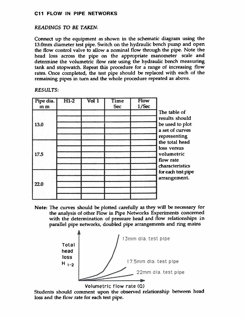
READINGS TO BE TAKEN;
Connect up the equipment as shown in the schematic diagram using the13.Omm diameter test pipe. Switch on the hydraulic benCh pump and openthe flow control valve to allow a nominal flow through the pipe. Note thehead loss across the pipe on the appropriate manometer scale anddetermine the volumetric flow rate using the hydraulic bench measuringtank and stopwatch. Repeat this procedure for a range of increasing flowrates. Once completed, the test pipe should be replaced with each of theremaining pipes in turn and the whole procedure repeated as above.
RESULTS:
Pipe dia.mm
Hl-2 Voll TimeSec
Flowl/Sec
The table ofresults shouldbe used to plota set of curvesrepresentingthe total headloss versusvolumetricflow ratecharacteristicsfor eoch tESt pipearrangement.
13.0
17.5
22.0
Note: The curves should be plotted carefully as they will be necessary forthe analysis of other Flow in Pipe Networks Experiments concernedwith the determination of pressure head and flow relationships inparallel pipe networks, doubled pipe arrangements and ring mains
Tota1head10ssH 1-2
Vo1umetr1c flow rate (0)Students should comment upon the observed relationship between headloss and the flow rate for each test pipe.
C11 FLOW IN PIPE NETWORKS
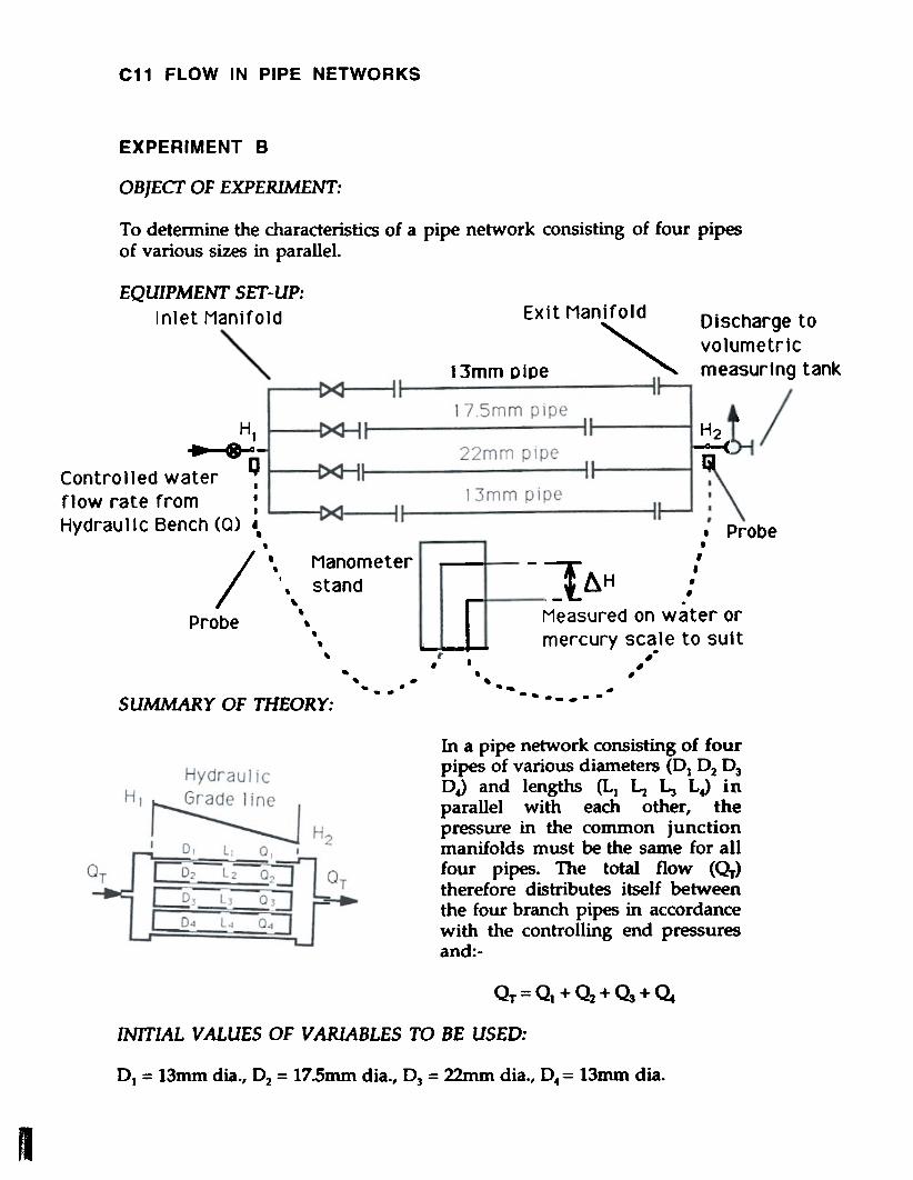
EXPERIMENT B
OBJECT OF EXPERIMENT:
To determine the characteristics of a pipe network consisting of four pipesof various sizes in parallel.
EXi t Manifold
13mm DiDe ""
Discharge tovolumetricmeasuring tank
I
HI~:-:-
Controlled water ~fJow rate from' .Hydraulic Bench (0) "
H2--<Ii
~
,/ I,.
Probe
Manometerstand
~
.,.. [.,,, '--.J
.- ,, .- .- . .SUMMARY OF THEORY:
In a pipe network consisting of fourpipes of various diameters (Dt D2 D3DJ and lengths (Lt L2 ~ LJ inparallel with each other, thepressure in the common junctionmanifolds must be the same for allfour pipes. The total flow (~)therefore distributes itself betweenthe four branch pipes in accordancewith the controlling end pressuresand:-
QT=Q. +Q2+~+Q.
INITIAL VALUES OF VARIABLES TO BE USED:
01 = 13mm dia., O2 = 17.5mm dia., 03 = 22mm dia., 0.= 13mm dia.
I
EQUIPMENT SET-UP:Inlet Manifold
. Probe.
-~ ""I ~H jMeasured on water ormercury scale to suit
,.. ', .-

C11 FLOW IN PIPE NETWORKS
READINGS TO BE TAKEN:
Connect up the equipment as shown in the schematic diagram. Switch 0 nthe hydraulic bench pump and open the flow control valve to allow anominal flow through the pipe network. Note the head loss across thenetwork on the appropriate manometer scale and determine thevolumetric flow rate using the hydraulic bench measuring tank and astopwatch. Repeat this procedure for a range of increasing flow rates.
RESULTS:
Results Calculations
I,Ql/sec
HJ-2 Voll Timesec
Flowl/sec
Q]l/sec
Q2l/sec
~l/sec
Q.l/sec
TestNo
Students should determine the flow in each branch pipe using therespective calibration curves for each individual size of pipe used.
Note: These calibration curves must be determined prior to thisexperiment and the procedure is fully explained on DataSheet A 'Calibration of Network Components'. The flows ineach branch pipe should be added together and the resultcompared to the total flow measured using the hydraulicbench. Correlation will be noted between the total flowvalues determined by these two experimental approaches butstudents should account for any observed minor differences.
Students should observe and comment upon the magnitude of the flowrates in each pipe and account practically for their respective differences.Advanced students should calculate the theoretical flow rate in any pipefor a given head difference from a knowledge of the pipe geometry and anestimated pipe friction factor. The values so calculated should be comparedto the experimentally determined values.
Students should suggest practical situations where parallel pipe networksmight be found.
This experiment may be repeated for alternative networks ofonly two or three pipes in parallel by connecting anappropriate network arrangement.
Note:

~~~
To determine the characteristics of a pipe network consisting of three pipesof different sizes in series.
~
EX1t Manifo1d
3mm p1pe ""
~
DIscharge tovolumetricmeasur1ng tank
H222mm plpe
~~
H47.5mm pipe
~
.c a/,
/,
prObe: Outlet pIpe,,
~ . I--- ..-. . 1/~ 4/ I--- ---. .
-Controlled water41ow rate fromJydpau11c Bench (0)
~~~~
--""1 ~ H ,:Measured on water ormercury scale to suit
..
~
,
~~
~
~~
-
~
-'- '
~
A pipeline consisting ofvarious diameter(Dt D2 DJand lengths (Lt ~ LJ carryinga flow rate (Q) will have atotal head loss (HT> along thewhole length given by:
~~~
.I.I.
.I.I.
~
L. i~ HT= H1-2 + ~.3 + Hw..a
C11 FLOW IN PIPE NETWORKS
EXPERIMENT C
OBJECT OF EXPERIMENT:
EQUIPMENT SET-UP:
Inlet Manifold
"" 1I II'
H ~ . . .11--- a--".~ - i .. .~cc. ,- Q
.
.
.
I'"Probe, ManometerC I ~,stand oup er ~
., .~ ,- ., .- .- .
SUMMARY OF THEORY:HydrauJ jcGrade 1;ne
~ - H- - -"-c-
~ 2 H~-~ :1
The component head loss from each section is the summation of the pipefriction loss plus other losses arising from changes of section, junctions,bends and valves in that section.
rHr~
4

C11 FLOW IN PIPE NETWORKS
INITIAL VALUES OF VARIABLES TO BE USED:
01 = 13mm dia., D2 = 22mm dia., D3 = 17.5mm dia.
READINGS TO BE TAKEN:
Connect up the equipment as shown in the schematic diagram. Switch onthe hydraulic bench pump and open the flow control valve to allow anominal flow through the pipe network. Connect the remote probes acrosseach pipe section in turn and measure the head loss on the appropriatemanometer scale. Measure the total head loss across the complete pipenetwork and determine the volumetric flow rate using the hydraulicbench measuring tank and a stopwatch. Repeat this procedure for a rangeof increasing flow rates.
RESULTS:
TIMEsec
FLOW1/S8:
IAH HI-4 VOLtTest No "1-2 H1.-3 "3-4
Students should interpret the results to verify for themselves, that thetotal head loss across the series network (Ht-4) is equal to the sum of the 3component head losses (AI.H = Ht-2 + ~-3 + H~) for all flow rates.
Students should observe and comment upon the magnitude of the 3component head losses and account practically for their respectivedifference. Advanced students should calculate the theoretical head loss inany section for a given flow from a knowledge of the pipe geometry and anestimated pipe friction factor. The values so calculated should be comparedto the experimentally measured values.
Why is a knowledge of the energy degradation in a pipe network ofimportance to a system designer? Suggest practical situations where seriespipe networks might be found.
This experiment may be repeated for an alternative networkof only two different pipes in series by connecting anappropriate pipework arrangement.
Note:

C11 FLOW IN PIPE NETWORKS
EXPERll\IIENT D
OBJECT OF EXPERIMENT:
To determine the characteristics of a ring main supplied with water at oneinlet point and supplying water at three outlet points.
EQUIPMENT SET-UP:
Outlet pipenlet Manifold
\
3 Discharges tovolumetricmeasuring tank
17.Smm pipeH2 I
:Hjut let pipes
~JControlled water ~flow rate from .
.Hydraulic Bench <0> '.
- ~-~-'13mm pipe
~..-.
17.Smm pipe ~'\PrObe.
/",Probe
Manometerstand
- . b.H ,!
_t. ,Measured on water ormercury scale to suit
,--
--.The solution of any ring mainproblem is to determine the head(H) at every junction point and theflow (Q) in every part of the ringfrom a knowledge of the supplyquantity and the several quantities.Clearly for any junction point thealgebraic sum of the flows must bezero: e.g. at point (3)Q2+~+~t3=O
°out3
INITIAL VALUES OF VARIABLES TO BE USED:
01 = 17.5mm dia., O2 = 22mm dia., 03 = 13mm dia., O.a = 17.5mm dia.
READINGS TO BE TAKEN:
Connect up the equipment as shown in the schematic diagram. Switch onthe hydraulic bench pwnp and open the flow control valve to admit anominal flow to the ring main. Connect the remote probes across eachpipe in turn and measure the differential head on the appropriatemanometer scale. Determine the total volwnetric flow rate from the threeoutlets using the hydraulic bench measuring tank and a stopwatch. Thisprocedure may be repeated for other flow rates if required.
b.;e-4

FLOW IN PIPE NETWORKS
RESULTS;
a) Results
Ht-2 "2-3 ~H1..TestNo
Vol1
Timesec
Flowl/sec
b) Calculations
Qll/sec
TestNo
Q2!!~
~l/sec
Q.l/sec
~t2
l/secOouul/sec
L~tl/sec
~l/sec
Students should determine the flow rate and direction in each pipe of thering main (Ql Q2 ~ ~) from the respective differential headmeasurements. The flow rates may be deduced from the calibration curvesfor the various sizes of pipe used in each section of the ring.
These calibration curves must be determined prior to thisexperiment and the procedure is fully explained on DataSheet A 'Calibration of Network Components'. The directionof flow in each pipe is determined by that of the fallingpressure gradient.
The outflow from each of the three discharge points should be calculatedby adding algebraically the flows in each pipe meeting at that outflow.Finally, the three outflows should be added and compared to the measuredinflow to check the measured inflow to check the validity of the ringanalysis.
Students should comment upon the distribution on flow around the ringand suggest practical situations for the use of ring mains.
Advanced students may wish to analyse the ring main theoretically andpredict the flow and head distribution from a knowledge of ring geometryand basic assumptions regarding pipe friction factors and inlet conditions.Several methods are available, some using techniques of successiveapproximation.
D-2

C11 FLOW IN PIPE NETWORKS
EXPERIMENT E
OBJECT OF EXPERIMENT:
To show that the flow carrying capacity of a pipeline is increased when thepipe is doubled by a parallel pipe for a part of its length.
.I EQUIPMENT SET-UP:
~
CouplerCouplerInlet Manjfo1d
\
Outlet pipe
I 3mm plpe
H~'-
. toI Vo1umetric
measuring tank22mm ptpebl HI
~:-~-0 Controlled water ~- flow rate from .
.n Hydraulic Bench (0) '--
l1 / "1
Probe
,,I.Manometer
stand,,-
Probe- ""J: ~H
Measured on water ormercury scale to suit
,....,I,
n.~~
, ., . .,
.~ -.. - ',.,
SUMMARY OF THEORY:
In order to increase the flowcarrying capacity, a pipelineconsisting of 2 sections of pipehaving diameters (D1 OJ andlengths (L} LJ in series can bedoubled over the length L1 by aparallel pipe having diameter D3and length L3 for this network thefollowing relationships apply:
0~.1 03~
'~c
0. t. a,
= head loss in pipe 01 + head loss in pipe O2= head loss in pipe OJ + head loss in pipe O2
Head loss along pipe 01
Flow rate O2 = Ql + ~
Length L1 =i.a

C11 FLOW IN PIPE NETWORKS
INITIAL VALUES OF VARIABLES TO BE USED:IDt = 13mm dia., D2 = 22mm dia., D3 = 17.5mm dia.
READINGS TO BE TAKEN:
1\~
Connect up the equipment up as shown in the diagram but with valveNo.3 closed so as to connect a series pipeline only. Switch on the hydraulicbench pump and open the flow control valve to allow a nominal flowthrough the pipes. Note the head loss on the appropriate manometer scaleand determine the volumetric flow rate using the hydraulic benchmeasuring tank and a stopwatch. Repeat this procedure for a range ofincreasing flow rates.
The whole procedure should next be repeated but with valve No.3 openso as to connect the doubled pipe circuit.
RES UL TS:
a) Series pipeline only~,
I
b) Doubled pipeline
Seriespipelineonly
I
Students should plot a curve of head loss versusflow rate for the two pipeline arrangementstested. The resulting graph will show theimproved flow ca~g capacity of the doubled
D~Ub 1.ed pipeline. Students should comment upon thepipeline effect of doubling and suggest practical situations
where doubling might be used.
Flow rate (0)

C11 FLOW IN PIPE NETWORKS
Advanced students may wish to deduce theoretically the flow in eachbranch of the doubled pipe from:
~
Q2 Q21 - 3
0;-0:
~
and Q2=Q1 +~
assuming that the doubled pipes share the same friction factor.
Q
I

GENERAL SAFETY RULES
1 Follow Relevant Instructions
a
b
Before attempting to install, commission or operate equipment, allrelevant suppliers/manufacturers instructions and local regulationsshould be understood and implemented.It is irresponsible and dangerous to misuse equipment or ignoreinstructions, regulations or warnings.Do not exceed specified maximum operating conditions (eg.temperature, pressure, speed etc.)
c
2 Installation
a
b
c
d
e
f
Use lifting tackle where possible to install heavy equipment. Wheremanual lifting is necessary beware of strained backs and crushedtoes. Get help from an assistant if necessary. Wear safety shoeswhere appropriate.Extreme care should be exercised to avoid damage to the equipmentduring handling and unpacking. When using slings to liftequipment, ensure that the slings are attached to structuralframework and do not foul adjacent pipework, glassware etc. Whenusing fork lift trucks, position the forks beneath structuralframework ensuring that the forks do not foul adjacent pipework,glassware etc. Damage may go unseen during commissioningcreating a potential hazard to subsequent operators.Where special foundations are required follow the instructionsprovided and do not improvise. Locate heavy equipment at lowlevel.Equipment involving inflammable or corrosive liquids should besited in a containment area or bund with a capacity 50% greater thanthe maximum equipment contents.Ensure that all services are compatible with the equipment and thatindependent isolators are always provided and labelled. Use reliableconnections in all instances, do not improvise.Ensure that all equipment is reliably earthed and connected to anelectrical supply at the correct voltage. The electrical supply mustincorporate a Residual Current Device (RCD) (alternatively calledan Earth Leakage Circuit Breaker - ELCB) to protect the operatorfrom severe electric shock in the event of misuse or accident.Potential hazards should always be the first consideration whendeciding on a suitable location for equipment. Leave sufficient spacebetween equipment and between walls and equipment.
g

Commissioning3
Ensure that equipment is commissioned and checked bycompetent member of staff before permitting students to operate it.
aa
Operation4
a
b
c
Ensure that students are fully aware of the potential hazards whenoperating equipment.Students should be supervised by a competent member of staff at alltimes when in the laboratory. No one should operate equipmentalone. Do not leave equipment running unattended.Do not allow students to derive their own experimental proceduresunless they are competent to do so.Serious injury can result from touching apparently stationaryequipment when using a stroboscope to 'freeze' rotary motion.
d
5 Maintenance
a Badly maintained equipment is a potential hazard. Ensure that acompetent member of staff is responsible for organisingmaintenance and repairs on a planned basis.Do not permit faulty equipment to be operated. Ensure that repairsare carried out competently and checked before students arepermitted to operate the equipment.
b
Using Electricity6
a
b
c
d
At least once each month, check that ELCB's (RCCB's) are operatingcorrectly by pressing the TEST button. The circuit breaker must tripwhen the button is pressed (failure to trip means that the operator isnot protected and a repair must be effected by a competentelectrician before the equipment or electrical supply is used).Electricity is the commonest cause of accidents in the laboratory.Ensure that all members of staff and students respect it.Ensure that the electrical supply has been disconnected from theequipment before attempting repairs or adjustments.Water and electricity are not compatible and can cause seriousinjury if they come into contact. Never operate portable electricappliances adjacent to equipment involving water unless someform of constraint or barrier is incorporated to prevent accidentalcontact.Always disconnect equipment from the electrical supply when notin use.
e
b
A voiding fires or explosion7
Ensure that the laboratory is provided with adequate fireextinguishers appropriate to the potential hazards.Where inflammable liquids are used, smoking must be forbidden.Notices should be displayed to enforce this.Beware since fine powders or dust can spontaneously ignite undercertain conditions. Empty vessels having contained inflammableliquids can contain vapour and explode if ignited.Bulk quantities of inflammable liquids should be stored outside thelaboratory in accordance with local regulations.Storage tanks on equipment should not be overfilled. All spillagesshould be immediately cleaned up, carefully disposing of anycontaminated cloths etc. Beware of slippery floors.When liquids giving off inflammable vapours are handled in thelaboratory, the area should be ventilated by an ex-proof extractionsystem. Vents on the equipment should be connected to theextraction system.Students should not be allowed to prepare mixtures for analysis orother purpose without competent supervision.
a
b
c
d
e
f
g
Handling poisons, corrosive or toxic materials8
a
b
c
d
Certain liquids essential to the operation of equipment, for examplemercury, are poisonous or can give off poisonous vapours. Wearappropriate protective clothing when handling such substances.Clean up any spillage immediately and ventilate areas thoroughlyusing extraction equipment. Beware of slippery floors.Do not allow food to be brought into or consumed in the laboratory.Never use chemical beakers as drinking vessels.Where poisonous vapours are involved, smoking must beforbidden. Notices should be displayed to enforce this.Poisons and very toxic materials must be kept in a locked cupboardor store and checked regularly. Use of such substances should besupervised.When diluting concentrated acids and alkalis, the acid or alkalishould be added slowly to water while stirring. The reverse shouldnever be attempted.
e
9 A voiding cuts and bums
a
b
Take care when handling sharp edged components. Do not exertundue force on glass or fragile items.Hot surfaces cannot in most cases be totally shielded and canproduce severe burns even when not 'visibly hot'. Use commonsense and think which parts of the equipment are likely to be hot.
1

1
10 Eye protection
~
a
b
~
Goggles must be worn whenever there is a risk to the eyes. Risk mayarise from powders, liquid splashes, vapours or splinters. Beware ofdebris from fast moving air streams. Alkaline solutions areparticularly dangerous to the eyes.Never look directly at a strong source of light such as a laser orXenon arc lamp. Ensure that equipment using such a source ispositioned so that passers-by cannot accidentally view the source orreflected ray.Facilities for eye irrigation should always be available.c
Ear protection11
Ear protectors must be worn when operating noisy equipment.a
Clothing12
a Suitable clothing should be worn in the laboratory. Loose garmentscan cause serious injury if caught in rotating machinery. Ties, ringson fingers etc. should be removed in these situations.Additional protective clothing should be available for all membersof staff and students as appropriate.
b
13 Guards and safety devices
a
b
c
d
Guards and safety devices are installed on equipment to protect theoperator. The equipment must not be operated with such devicesremoved.Safety valves, cut-outs or other safety devices will have been set toprotect the equipment. Interference with these devices may create apotential hazard.It is not possible to guard the operator against all contingencies. Usecommon sense at all times when in the laboratory.Before starting a rotating machine, make sure staff are aware how tostop it in an emergency.Ensure that speed control devices are always set at zero beforestarting equipment.
e
14 First aid
a
b
If an accident does occur in the laboratory it is essential that first aidequipment is available and that the supervisor knows how to use it.A notice giving details of a proficient first-aider should beprominently displayed.A 'short list" of the antidotes for the chemicals used in a particularlaboratory should be prominently displayed.
c
I d