flow measurement - fondon redes y fluidos, s.l.flow measurement is based on faraday’s law of...
TRANSCRIPT

Flow measurement Product overview

4-5 Product selection
6-7 Highlights of the KROHNE devices
8-17 Electromagnetic flowmeters
18-25 Variable area flowmeters
26-33 Ultrasonic flowmeters
34-41 Mass flowmeters
42-47 Vortex flowmeters
48-55 Differential pressure flow measurement
56-61 Flow controllers
62-63 Communication technology
64-65 KROHNE services
66-67 Calibration
Contents
KROHNE trademarks:KROHNECalSysCARGOMASTEREcoMATEEGMKROHNE CareOPTIBATCHOPTIBRIDGEOPTIFLEXOPTIFLUXOPTIMASSOPTIQUADOPTISONICOPTISOUNDOPTISWIRLOPTISWITCHOPTISYSOPTIWAVEPipePatrolWATERFLUXSENSOFITSMARTBASESMARTMAC Trademarks of other owners: Amphenol FDT Group FOUNDATION™ fieldbus HART HASTELLOY Metaglas PACTware PROFIBUS® VARINLINE

Dear Customers,
Communication techniques are becoming ever more complex, from the field through to the control level. At the same time the demands for recording physical measured variables such as flow rates, fill levels, temperature, pressure and analysis parameters are constantly growing. The principal requirement in this respect is absolute reliability of the measured values. This means the measuring equipment, even when subjected to disruptive influences such as changing flow profiles or inclusion of gas bubbles, must always deliver reliable values, and above all must guarantee virtually 100 % security against failure.
“Measure the facts“ means not only reliable measurement of standard process variables – even under the most difficult process conditions – but also clear and precise process diagnostics right through to the material composition of the medium. Both of these contribute to improved process control and allow remarkable increases in process efficiency and production.
In order to guarantee this for you, more than 400 engineers in the worldwide KROHNE Group are continuously engaged in research into promising technologies for the future, in pursuit of improved measurement and further developments. We are a family-owned enterprise and we take our responsibilities seriously. We have permanent representation in more than 130 countries and employ more than 3,500 people in order to bring you highly innovative products from a single source, and tailor-made technical solutions to your measurement requirements, now and in the future.
Letter from the Corporate Management
Michael Rademacher-Dubbick Stephan Neuburger

KROHNE has unique expertise when it comes to flow measure-ment. We hold over 1,000 patents relating to flow products and don’t just demonstrate our ability with standard applications but also with applications that are demanding, requiring custom solutions. For us, customer orientation starts as early as re-search and development. Many of our products which are considered today’s industrial standards, were developed in cooperation with our customers. Today, users around the world benefit from KROHNE innovation: Electromagnetic flowmeters with ceramic liners for highly corrosive media in chlorine chemistry. Mass flowmeters with just one straight tube – ideal for highly viscous media and low flow speeds. Ultrasonic flow-meters for custody transfer, working according to the time-of-flight method. Vortex measuring devices with integrated pressure and temperature compensation. And variable area flowmeters: they established KROHNE’s business in 1921, today we can’t imagine KROHNE without them, if a local display is to ensure the redundancy and the certainty of the system.
Due to their repeatability and accuracy, our flowmeters are installed as reference-meters on standard liquid flow calibration-rigs of national metrology institutes such as PTB (Germany), NMi/EuroLoop (the Netherlands) and NMiJ (Japan).
The solution for every application
Online configurator
For detailed device selection, take advantage of our online platform Configure It. It’s quick and easy to find the right product variant for you, to check the availability of the selected product or to request a non-binding quote. For more information about Configure It go to www.krohne-direct.com

5
Product selection list
This table will help you in selecting the right measuring principle for your application
x = suitable, o = suitable under certain conditions, – = not suitable
Electro- magnetic
flowmeters
Variable area
flowmeters
Ultrasonic flowmeters
Mass flowmeters
Vortex flowmeters
Differential pressure
flow measurement
Flow controllers
Page 8-17 Page 18-25 Page 26-33 Page 34-41 Page 42-47 Page 48-55 Page 56-61
Liquids
Liquids (e.g. water) x x x x x x x
Low flow rates (< 2 l/h) x x – x – o –
High flow rates (> 100000 m3/h) x – x – – x x
Non-conductive liquids – x x x x x o
Viscous media x x o x o x o
Gases
Industrial gases – x x x x x –
Low flow rates (< 20 l/min) – x o x – x –
High flow rates – o x x x x –
Steam – o x o x x –
Special applications
Slurry, media with solids x – – x – o –
Emulsions (oil/water) o x o x o x o
Corrosive liquids (acids, alkalis) x x x x o x o
Corrosive gas flows – o x o o x –
Bi-directional measurements x – x x – x o
Version
2-wire x x – – x x x
4-wire x – x x – – –
Product selection

6 Highlights of the KROHNE devices
MFC 400 for mass flowmetersUFC 400 for ultrasonic flowmeters
IFC 300 for electromagnetic flowmetersMFC 300 for mass flowmetersUFC 300 for ultrasonic flowmetersGFC 300 for ultrasonic gas flowmeters
User-friendliness is traditionally a top priority at KROHNE: whether during installation, commissioning, operation or communication – high-end technology only makes sense if it is simple and convenient for the customer to use.
That is why at KROHNE, user-friendliness begins with the electronics. Our development and application engineers have worked for years to develop a compre-hensive design known as the General Device Concept – GDC for short.
What does it all mean? First of all, it features a uniform user interface to speed up the commissioning of the devices. Secondly, it boasts extensive device and process diagnostic functions, which can be exceeded by the Toolbox module. Thirdly, it’s easy to integrate fieldbus interfaces such as PROFIBUS® and FOUNDATION™ fieldbus thanks to the high degree of modularity. And lastly, it’s an electronics package that can be used in various housing shapes.
The high-end position in terms of functionality and accuracy is occupied by the electromagnetic converter IFC 300. It offers full diagnostic capabilities and offers the maximum freedom in defining process parameters and settings for even the most complex measuring applications.
With IFC 100, its diagnostic capabilities and its hazard-ous area approvals we offer a sophisticated solution for general applications. Optionally it even provides communication protocols like PROFIBUS®, FOUNDATION™ fieldbus and Modbus.
The IFC 050 is the all-purpose device which boasts outstanding performance. Not only when it comes to measuring accuracy and diagnostics but also defines a new benchmark in terms of the price-performance ratio.
The converter MFC 400 is a further development of the GDC concept, providing new performance features such as Entrained Gas Management™ for mass flowmeters.
The most recent member of the GDC family is the VFC 200. The converter for Vortex flowmeters is the first 2-wire device in this group and – thanks to its develop-ment according to the latest edition of IEC 61508 – ideally suitable for safety-related applications (SIL 2).
GDC concept: An electronics concept from which everybody benefits
VFC 200 for Vortex flowmeters
IFC 100 for electromagnetic flowmeters
IFC 050 for electromagnetic flowmeters

7
User-friendliness begins with selecting the right display and control elements.
All devices feature a large, high-contrast display which makes it possible to display plain text information as well as graphic information such as the trend develop-ment of the flow.
Operation is simple and convenient thanks to a user-friendly interface with four optical buttons. Not only does it look good – it’s also extremely practical.
At KROHNE, we believe in the concept of modularity when it comes to offering our customers the mea- suring solution best suited to their process. Both our IFC and MFC converters can be freely combined with all devices in the OPTIFLUX and OPTIMASS lines. This modularity is also reflected in the names of the devices. For example, the OPTIFLUX 1300 is a combi- nation of the OPTIFLUX 1000 sensor and the IFC 300 converter.
Human Machine Interface (HMI): Simply clever, simply well thought-out
Modular product lines: Many combinations for one customised solution
For example, the glass cover which protects the display from dirt and dust does not have to be re- moved during parameterization or operation.Using the Quick Setup menu, the user can quickly adapt the OPTIFLUX to the application.
The converter can communicate with the user in many languages including German, English, French and Spanish.
OPTICHECK: On-site verification tool for KROHNE flowmeters
The OPTICHECK is the essential tool for making sure that your installed flowmeters are performing to specification. When you connect the tool in-line on site, it gathers measuring data to ensure that the flowmeter is performing within 1 % of the factory calibration. The baseline can be historic repair data from the factory or on-site test results after perfor-ming a full verification.

IFC 300 R Rack-mounted
IFC 300 W Wall-mounted
IFC 300 F Field housing
IFC 300 C General purpose
IFC 100 W Wall-mounted
IFC 100 C Standard applications
The modular product line
OPTIFLUX 1000 The sandwich (wafer) solution for compact installation
OPTIFLUX 2000 The all-round solution for the water and wastewater industry
WATERFLUX 3000 The solution for measuring small and large flows without requiring inlets or outlets
OPTIFLUX 4000 The all-round solution for the process industry
OPTIFLUX 5000 sandwich Ceramic measuring tube: maximum media and abrasion resistance and accuracy
OPTIFLUX 5000 flange Ceramic measuring tube: maximum media and abrasion resistance and accuracy
OPTIFLUX 6000 The hygenic solution for the food and pharmaceutical industry
Converters
Flow sensors
IFC 050 W Display/Blind: Wall-mounted
IFC 050 C Display/Blind: Basic applications

Electromagnetic flowmeters
WATERFLUX 3070 The battery operated solution for large turndown ratios and small spaces with no inlets or outlets
The specialists
OPTIFLUX 4040 C 2-wire device
OPTIFLUX 7300 C sandwich With non wetted capacitive electrodes and ceramic liner
BATCHFLUX 5500 For volumetric filling systems in the beverage industry
OPTIFLUX 7300 C flange With non wetted capacitive electrodes and ceramic liner
TIDALFLUX 2300 F For partially filled pipelines, Ex Zone 1
OPTICHECK On-site verification tool for calibration verification and documentation
Accessoires

10 Electromagnetic flowmeters
The measuring principle
As early as 1832, Michael Faraday tried to determine the speed of the current in the Thames by measuring the voltage induced in flowing water by the earth’s magnetic field. Electromagnetic flow measurement is based on Faraday’s law of induction. According to this law, a voltage is induced when an electric conductive fluid flows through the magnetic field of an electro-magnetic flowmeter. This voltage is proportional to the flow velocity of the medium.
Electromagnetic flowmeters
Highlights:
• Minimal or no inlets/outlets
• All KROHNE electromagnetic flowmeters are wet-calibrated in a direct comparison of volumes
• Large choice of liner materials suitable for drinking water, wastewater, chemicals, SIP/CIP and solids
• Suitable for use in custody transfer applications
• Measurement is independent of the flow profile
• Abrasion and corrosion-resistant liners available
• Ceramic measuring tubes and liners available for flange and sandwich versions, also with non-wetted electrodes (capacitives flowmeter)
• Specific models for partially filled pipes
• Virtual reference option: grounding electrodes and grounding rings can be left out
• Electric conductivity of medium can be used for detection of product change
• For high bubble content, high solids content and pulsating flow
• Secure handling of rapid medium changes and pH jumps
• Zero-point stability regardless of changes in medium properties
• Nominal sizes DN 2.5 to 3,000
• 3x100%-diagnostics (application and device diagnostic, out-of-spec-test) exceeds NAMUR requirements
The induced voltage is picked up either by two electrodes in contact with the medium or by capacitive electrodes with no contact to medium and supplied to a signal converter.
A signal converter amplifies the signal and converts it into a standard signal (4…20 mA) as well as to a frequency/pulse signal (e.g. one pulse for every cubic meter of measured medium that flows through the measuring tube).
Magnetic field
Voltage
Electrode Field coil
Induced voltage proportional to flow

11Electromagnetic flowmeters
As founder and world market leader in electromagnetic flowmeter technology, we have been impressing our customers with innovation for more than 60 years, innovations that continue to set the standard for the competition. Our OPTIFLUX product line is an excellent example of this: a converter for all applications. A one-of-a-kind diagnostics package that can even look into the process. An intuitive operating concept featuring a quick start function for simple start-up.
Thanks to this unique combination of high-end technology and maximum user-friendliness, you will benefit in a wide range of industries: in the food and beverage industry, where fruit juices, milk and liquid hops must be mixed, dosed and filled under hygienic conditions. In the chemicals industry and in the pulp and paper industry, where our devices deal with acids, alkalis, pastes, sludges and other caustic media, or in the metal and mining industry where media with a high solid content are encountered on a daily basis.
We produce electromagnetic flowmeters in our plants in the Netherlands, Brazil, India and China. It is no wonder that the Physikalisch-Technische Bundesanstalt (PTB) in Braunschweig, Germany, relies on electromagnetic flowmeters from KROHNE in their calibration systems.
The standard for the competition: Electromagnetic flowmeters from KROHNE
Industries:
• Water and wastewater
• Chemical
• Food and beverage
• Pharmaceutical
• Power plants
• Pulp and paper
• Metal and mining
OPTIFLUX 4300 in the filtration system in the Haltern waterworks, Germany
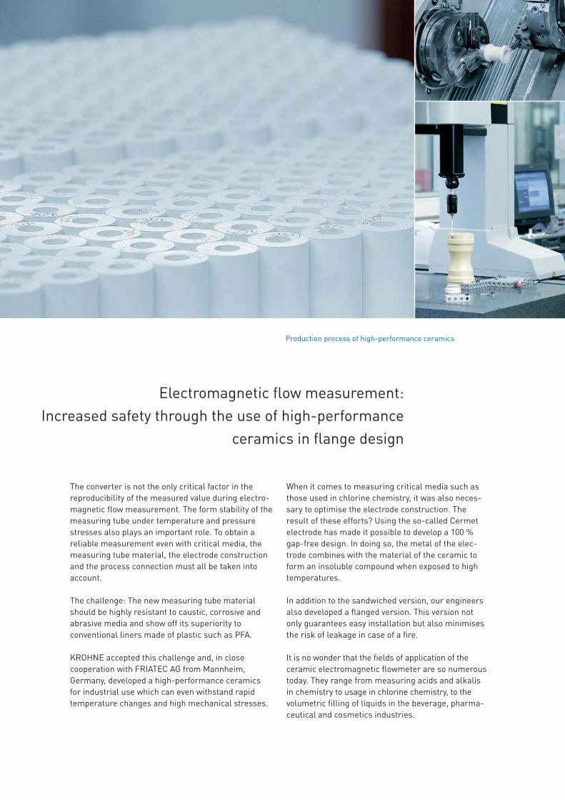
The converter is not the only critical factor in the reproducibility of the measured value during electro-magnetic flow measurement. The form stability of the measuring tube under temperature and pressure stresses also plays an important role. To obtain a reliable measurement even with critical media, the measuring tube material, the electrode construction and the process connection must all be taken into account.
The challenge: The new measuring tube material should be highly resistant to caustic, corrosive and abrasive media and show off its superiority to conventional liners made of plastic such as PFA.
KROHNE accepted this challenge and, in close cooperation with FRIATEC AG from Mannheim, Germany, developed a high-performance ceramics for industrial use which can even withstand rapid temperature changes and high mechanical stresses.
Electromagnetic flow measurement: Increased safety through the use of high-performance
ceramics in flange design
When it comes to measuring critical media such as those used in chlorine chemistry, it was also neces-sary to optimise the electrode construction. The result of these efforts? Using the so-called Cermet electrode has made it possible to develop a 100 % gap-free design. In doing so, the metal of the elec-trode combines with the material of the ceramic to form an insoluble compound when exposed to high temperatures.
In addition to the sandwiched version, our engineers also developed a flanged version. This version not only guarantees easy installation but also minimises the risk of leakage in case of a fire.
It is no wonder that the fields of application of the ceramic electromagnetic flowmeter are so numerous today. They range from measuring acids and alkalis in chemistry to usage in chlorine chemistry, to the volumetric filling of liquids in the beverage, pharma-ceutical and cosmetics industries.
Production process of high-performance ceramics

13Electromagnetic flowmeters
KROHNE offers its customers complete application and process diagnostics as well as an accuracy and linearity test (out-of-spec diagnostics) in addition to the usual device diagnostics for the OPTIFLUX line.
With the indicators supplied by OPTIFLUX and knowledge of the process, the user can detect the following application problems with a high degree of certainty:
• Gas bubbles• Electrode corrosion, deposits on electrodes• Short-circuit• Low conductivity of measured medium• Partial filling of measuring tube• Liner damage• External disrupting magnetic fields• Disrupted flow profile
During the out-of-spec test, a determination is made, both online and cyclically, as to whether the device is still within its specifications. In particular, the accura-cy is tested by feeding a test signal. The linearity of the device and the accuracy of the field current with which the magnetic field is generated are also checked.
Thanks to the 3x100%-diagnostics, the OPTIFLUX is much more than a simple flowmeter: it examines the process and provides the user with valuable infor-mation. In this respect, the OPTIFLUX even exceeds the requirements of VDI/VDE/NAMUR 2650.
Electromagnetic flowmeters: 3x100%-diagnostics for maximum certainty
Resistance measurement for detecting electrode covering, electrode short-circuit, excessively low conductivity and for measuring the conductivity and the coil temperature (media temperature)
Coil
Coil
Yes = accuracy o.k.
No = diagnostic message
Test signalMeasured
value = test signal?
Magnetic field polarity reversal for checking the flow profile and for detecting a partially filled measuring tube
At flow profile disturbance electrode voltage will be > 0V
Coil
Accuracy test by means of a cyclically fed test signal

14 Electromagnetic flowmeters
The modular product lineThe sandwich (wafer) solution for compact installation
The all-round solution for thewater and wastewater industry
The solution for measuring small and large flows without requiring inlets or outlets
The all-round solution for the process industry
Ceramic measuring tube: maximum media and abrasion resistance and accuracy
Ceramic measuring tube: maximum media and abrasion resistance and accuracy
The hygenic solution for the food and pharmaceutical industry
OPTIFLUX 1050 OPTIFLUX 2050 WATERFLUX 3050
Measuring accuracy ±0.5% of measured value above 0.5 m/s; depending on measuring sensor ±2.5 mm/s below 0.5 m/s; independent of measuring sensor
±0.5% of measured value above 0.5 m/s; depending on measuring sensor ±2.5 mm/s below 0.5 m/s; independent of measuring sensor
±0.5% of measured value above 0.5 m/s; depending on measuring sensor ±2.5 mm/s below 0.5 m/s; independent of measuring sensor
- - - ±0.5% of measured value above 0.5 m/s; depending on measuring sensor ±2.5 mm/s below 0.5 m/s; independent of measuring sensor
Electrical conductivity ≥5 μS/cm (water ≥20 μS/cm) ≥5 μS/cm (water ≥20 μS/cm) ≥5 μS/cm (water ≥20 μS/cm) - - - ≥5 μS/cm (water ≥20 μS/cm)Process conditions Solid content <10% Solid content <10% Solid content <10% - - - Solid content <10%Outputs Current, pulse, status Current, pulse, status Current, pulse, status - - - Current, pulse, statusPower supply 100…230 VAC, 24 VDC 100…230 VAC, 24 VDC 100…230 VAC, 24 VDC - - - 100…230 VAC, 24 VDCProtection category: Compact (C)
Wall (W)IP66/67; NEMA 4/4X IP66/67; NEMA 4/4X IP66/67; NEMA 4/4X - - - IP66/67; NEMA 4/4X
OPTIFLUX 1100 OPTIFLUX 2100 WATERFLUX 3100 OPTIFLUX 4100 OPTIFLUX 5100 sandwich OPTIFLUX 5100 flange OPTIFLUX 6100
Measuring accuracy ±0.3% of measured value ±0.3% of measured value ±0.3% of measured value ±0.3% of measured value ±0.3% of measured value ±0.3% of measured value ±0.3% of measured valueElectrical conductivity ≥5 µS/cm (water ≥20 µS/cm) ≥5 µS/cm (water ≥20 µS/cm) ≥20 μS/cm ≥5 µS/cm (water ≥20 µS/cm) ≥5 µS/cm (water ≥20 µS/cm) ≥5 µS/cm (water ≥20 µS/cm) ≥5 µS/cm (water ≥20 µS/cm)Process conditions Solid content max. 10% Solid content max. 10% Clean drinking water Solid content max. 10% Solid content max. 10% Solid content max. 10% Solid content max. 10%Outputs Current, pulse, status Current, pulse, status Current, pulse, status Current, pulse, status Current, pulse, status Current, pulse, status Current, pulse, statusInputs Binary Binary Binary - - - -Communication HART®, FF, PA, DP, Modbus HART®, FF, PA, DP, Modbus HART®, FF, PA, DP, Modbus - - - -Power supply 100…230 VAC, 12…24 VDC,
24 VAC/DC100…230 VAC, 12…24 VDC, 24 VAC/DC
100…230 VAC, 12…24 VDC, 24 VAC/DC
100…230 VAC, 12…24 VDC, 24 VAC/DC 100…230 VAC, 12…24 VDC, 24 VAC/DC 100…230 VAC, 12…24 VDC, 24 VAC/DC 100…230 VAC, 12…24 VDC, 24 VAC/DC
Protection category: Compact (C) Field (F) Wall (W) 19" Rack (R)
IP66, 67; NEMA4X, 6 - - -
IP66, 67; NEMA4X, 6---
IP66, 67; NEMA4, 4X, 6 IP66, 67; NEMA4, 4X, 6--
IP66, 67; NEMA4X, 6 - - -
IP66, 67; NEMA4X, 6 - - -
IP66, 67; NEMA4X, 6 - - -
IP66, 67; NEMA4X, 6 - - -
OPTIFLUX 1300 OPTIFLUX 2300 WATERFLUX 3300 OPTIFLUX 4300 OPTIFLUX 5300 sandwich OPTIFLUX 5300 flange OPTIFLUX 6300
Measuring accuracy ±0.3% of measured value ±0.2% of measured value ±0.2% of measured value ±0.2% of measured value ±0.15% of measured value ±0.15% of measured value ±0.2% of measured valueElectrical conductivity ≥1 µS/cm (water ≥20 µS/cm) ≥1 µS/cm (water ≥20 µS/cm) ≥20 μS/cm ≥1 µS/cm (water ≥20 µS/cm) ≥1 µS/cm (water ≥20 µS/cm) ≥1 µS/cm (water ≥20 µS/cm) ≥1 µS/cm (water ≥20 µS/cm)Process conditions Solid content max. 70% Solid content max. 70% Clean drinking water Solid content max. 70% Solid content max. 70% Solid content max. 70% Solid content max. 70%Outputs Current, pulse, status Current, pulse, status Current, pulse, status Current, pulse, status Current, pulse, status Current, pulse, status Current, pulse, statusInputs Binary Binary Binary Binary Binary Binary BinaryCommunication HART®, FF, PA, DP, Modbus HART®, FF, PA, DP, Modbus HART®, FF, PA, DP, Modbus HART®, FF, PA, DP, Modbus HART®, FF, PA, DP, Modbus HART®, FF, PA, DP, Modbus HART®, FF, PA, DP, ModbusPower supply 85…250 VAC; 11…31 VDC;
20.5…26 VAC/DC85…250 VAC; 11…31 VDC; 20.5…26 VAC/DC
100…230 VAC, 12…24 VDC, 24 VAC/DC
85…250 VAC; 11…31 VDC; 20.5…26 VAC/DC
85…250 VAC; 11…31 VDC; 20.5…26 VAC/DC
85…250 VAC; 11…31 VDC; 20.5…26 VAC/DC
85…250 VAC; 11…31 VDC; 20.5…26 VAC/DC
Protection category: Compact (C) Field (F) Wall (W) 19" Rack (R)
IP66, 67; NEMA4, 4X, 6 IP66, 67; NEMA4, 4X, 6 IP65; NEMA4, 4X IP20; NEMA1
IP66, 67; NEMA4, 4X, 6 IP66, 67; NEMA4, 4X, 6 IP65; NEMA4, 4X IP20; NEMA1
IP66, 67; NEMA4, 4X, 6 IP66, 67; NEMA4, 4X, 6 IP65; NEMA4, 4X IP20; NEMA1
IP66, 67; NEMA4, 4X, 6 IP66, 67; NEMA4, 4X, 6 IP65; NEMA4, 4X IP20; NEMA1
IP66, 67; NEMA4, 4X, 6 IP66, 67; NEMA4, 4X, 6 IP65; NEMA4, 4X IP20; NEMA1
IP66, 67; NEMA4, 4X, 6 IP66, 67; NEMA4, 4X, 6 IP65; NEMA4, 4X IP20; NEMA1
IP66, 67; NEMA4, 4X, 6 IP66, 67; NEMA4, 4X, 6 IP65; NEMA4, 4X IP20; NEMA1
Measuring sensor OPTIFLUX 1000 OPTIFLUX 2000 WATERFLUX 3000 OPTIFLUX 4000 OPTIFLUX 5000 sandwich OPTIFLUX 5000 flange OPTIFLUX 6000
Process connection EN 1092-1 DN10…150; PN16, 40 DN25…3000; PN2.5…40 DN25…300; PN10, 16; DN350…600; PN10
DN2.5…2,000; PN6…40 DN2.5…100; PN16, 40 DN15…300; PN10, 16, 40 DN2.5…150; hygienic connections
Process connection ASME B16.5 3/8…6"; CL 150, 300 1…120"; CL 150, 300 1…12"; CL 150; 14"…24" CL 150 (10 bar/145 psi rated)
1/10…80"; CL 150, 300, 600, 900, 1500 1/10…4"; CL 150, 300 1/2…12"; CL 150, 300 1/10…6"; hygienic connections
Process temperature -25…+120°C; -13…+248°F -5…+90°C; +23…+194°F -5…+70°C; +23…+158°F -40…+180°C; -40…+356°F -40…+180°C; -76…+356°F -40…+180°C; -76…+356°F -40…+180°C; -40…+356°FAmbient temperature -25…+65°C; -13…+149°F -40…+65°C; -40…+149°F -40…+65°C; -40…+149°F -40…+65°C; -40…+149°F -40…+65°C; -40…+149°F -40…+65°C; -40…+149°F -40…+65°C; -40…+149°FMaterials liner PFA Polypropylen, hard rubber,
Polyolefin (PO)DN25…600: Rilsan PFA, PTFE, ETFE and
hard rubber, PUAluminium oxide, Zirconium oxide
Aluminium oxide, Zirconium oxide
PFA
Materials electrodes Hastelloy® Hastelloy®, titanium, stainless steel
Stainless steel 1.4301; AISI 304 Hastelloy®, titanium, tantalum, stainless steel, platinum, low noise
Cermet Cermet ≤DN150/6", stainless steel, HC4, titanium, tantalum, platinum ≥DN150/6"
Hastelloy®, stainless steel, titanium, tantalum, platinum
Sensor IP66, 67; NEMA4, 4X IP66, 67, 68; NEMA4, 4X, 6, 6P IP66, 67, 68; NEMA4, 4X, 6, 6P IP66, 67, 68; NEMA4, 4X, 6, 6P IP66, 67, 68; NEMA4, 4X, 6, 6P IP66, 67, 68; NEMA4, 4X, 6, 6P IP66, 67, 68; NEMA4, 4X, 6, 6PEx-Approvals - Ex, FM, CSA - Ex, FM, CSA Ex, FM, CSA Ex, FM, CSA Ex, FM, CSAOther approvals FDA, MI-001, MI-005 KTW, WRAS, KIWA, ACS,
OIML R49, MI-001, MI-005ACS, DVGW, TZW/UBA, NSF, WRAS, MI-001
FDA, OIML R49, R117, KIWA, MI-001, MI-005
FDA, MI-001, MI-005 FDA, MI-001, MI-005 FDA, 3A, EHEDG, MI-005
0PTIFLUX 1000 + IFC 100
OPTIFLUX 1000 + IFC 300
OPTIFLUX 1000
OPTIFLUX 2000 + IFC 100
OPTIFLUX 2000 + IFC 300
OPTIFLUX 2000
WATERFLUX 3000 + IFC 100
WATERFLUX 3000 + IFC 300
WATERFLUX 3000
0PTIFLUX 1000 + IFC 050
0PTIFLUX 2000 + IFC 050
WATERFLUX 3000 + IFC 050

15Electromagnetic flowmeters
The sandwich (wafer) solution for compact installation
The all-round solution for thewater and wastewater industry
The solution for measuring small and large flows without requiring inlets or outlets
The all-round solution for the process industry
Ceramic measuring tube: maximum media and abrasion resistance and accuracy
Ceramic measuring tube: maximum media and abrasion resistance and accuracy
The hygenic solution for the food and pharmaceutical industry
OPTIFLUX 1050 OPTIFLUX 2050 WATERFLUX 3050
Measuring accuracy ±0.5% of measured value above 0.5 m/s; depending on measuring sensor ±2.5 mm/s below 0.5 m/s; independent of measuring sensor
±0.5% of measured value above 0.5 m/s; depending on measuring sensor ±2.5 mm/s below 0.5 m/s; independent of measuring sensor
±0.5% of measured value above 0.5 m/s; depending on measuring sensor ±2.5 mm/s below 0.5 m/s; independent of measuring sensor
- - - ±0.5% of measured value above 0.5 m/s; depending on measuring sensor ±2.5 mm/s below 0.5 m/s; independent of measuring sensor
Electrical conductivity ≥5 μS/cm (water ≥20 μS/cm) ≥5 μS/cm (water ≥20 μS/cm) ≥5 μS/cm (water ≥20 μS/cm) - - - ≥5 μS/cm (water ≥20 μS/cm)Process conditions Solid content <10% Solid content <10% Solid content <10% - - - Solid content <10%Outputs Current, pulse, status Current, pulse, status Current, pulse, status - - - Current, pulse, statusPower supply 100…230 VAC, 24 VDC 100…230 VAC, 24 VDC 100…230 VAC, 24 VDC - - - 100…230 VAC, 24 VDCProtection category: Compact (C)
Wall (W)IP66/67; NEMA 4/4X IP66/67; NEMA 4/4X IP66/67; NEMA 4/4X - - - IP66/67; NEMA 4/4X
OPTIFLUX 1100 OPTIFLUX 2100 WATERFLUX 3100 OPTIFLUX 4100 OPTIFLUX 5100 sandwich OPTIFLUX 5100 flange OPTIFLUX 6100
Measuring accuracy ±0.3% of measured value ±0.3% of measured value ±0.3% of measured value ±0.3% of measured value ±0.3% of measured value ±0.3% of measured value ±0.3% of measured valueElectrical conductivity ≥5 µS/cm (water ≥20 µS/cm) ≥5 µS/cm (water ≥20 µS/cm) ≥20 μS/cm ≥5 µS/cm (water ≥20 µS/cm) ≥5 µS/cm (water ≥20 µS/cm) ≥5 µS/cm (water ≥20 µS/cm) ≥5 µS/cm (water ≥20 µS/cm)Process conditions Solid content max. 10% Solid content max. 10% Clean drinking water Solid content max. 10% Solid content max. 10% Solid content max. 10% Solid content max. 10%Outputs Current, pulse, status Current, pulse, status Current, pulse, status Current, pulse, status Current, pulse, status Current, pulse, status Current, pulse, statusInputs Binary Binary Binary - - - -Communication HART®, FF, PA, DP, Modbus HART®, FF, PA, DP, Modbus HART®, FF, PA, DP, Modbus - - - -Power supply 100…230 VAC, 12…24 VDC,
24 VAC/DC100…230 VAC, 12…24 VDC, 24 VAC/DC
100…230 VAC, 12…24 VDC, 24 VAC/DC
100…230 VAC, 12…24 VDC, 24 VAC/DC 100…230 VAC, 12…24 VDC, 24 VAC/DC 100…230 VAC, 12…24 VDC, 24 VAC/DC 100…230 VAC, 12…24 VDC, 24 VAC/DC
Protection category: Compact (C) Field (F) Wall (W) 19" Rack (R)
IP66, 67; NEMA4X, 6 - - -
IP66, 67; NEMA4X, 6---
IP66, 67; NEMA4, 4X, 6 IP66, 67; NEMA4, 4X, 6--
IP66, 67; NEMA4X, 6 - - -
IP66, 67; NEMA4X, 6 - - -
IP66, 67; NEMA4X, 6 - - -
IP66, 67; NEMA4X, 6 - - -
OPTIFLUX 1300 OPTIFLUX 2300 WATERFLUX 3300 OPTIFLUX 4300 OPTIFLUX 5300 sandwich OPTIFLUX 5300 flange OPTIFLUX 6300
Measuring accuracy ±0.3% of measured value ±0.2% of measured value ±0.2% of measured value ±0.2% of measured value ±0.15% of measured value ±0.15% of measured value ±0.2% of measured valueElectrical conductivity ≥1 µS/cm (water ≥20 µS/cm) ≥1 µS/cm (water ≥20 µS/cm) ≥20 μS/cm ≥1 µS/cm (water ≥20 µS/cm) ≥1 µS/cm (water ≥20 µS/cm) ≥1 µS/cm (water ≥20 µS/cm) ≥1 µS/cm (water ≥20 µS/cm)Process conditions Solid content max. 70% Solid content max. 70% Clean drinking water Solid content max. 70% Solid content max. 70% Solid content max. 70% Solid content max. 70%Outputs Current, pulse, status Current, pulse, status Current, pulse, status Current, pulse, status Current, pulse, status Current, pulse, status Current, pulse, statusInputs Binary Binary Binary Binary Binary Binary BinaryCommunication HART®, FF, PA, DP, Modbus HART®, FF, PA, DP, Modbus HART®, FF, PA, DP, Modbus HART®, FF, PA, DP, Modbus HART®, FF, PA, DP, Modbus HART®, FF, PA, DP, Modbus HART®, FF, PA, DP, ModbusPower supply 85…250 VAC; 11…31 VDC;
20.5…26 VAC/DC85…250 VAC; 11…31 VDC; 20.5…26 VAC/DC
100…230 VAC, 12…24 VDC, 24 VAC/DC
85…250 VAC; 11…31 VDC; 20.5…26 VAC/DC
85…250 VAC; 11…31 VDC; 20.5…26 VAC/DC
85…250 VAC; 11…31 VDC; 20.5…26 VAC/DC
85…250 VAC; 11…31 VDC; 20.5…26 VAC/DC
Protection category: Compact (C) Field (F) Wall (W) 19" Rack (R)
IP66, 67; NEMA4, 4X, 6 IP66, 67; NEMA4, 4X, 6 IP65; NEMA4, 4X IP20; NEMA1
IP66, 67; NEMA4, 4X, 6 IP66, 67; NEMA4, 4X, 6 IP65; NEMA4, 4X IP20; NEMA1
IP66, 67; NEMA4, 4X, 6 IP66, 67; NEMA4, 4X, 6 IP65; NEMA4, 4X IP20; NEMA1
IP66, 67; NEMA4, 4X, 6 IP66, 67; NEMA4, 4X, 6 IP65; NEMA4, 4X IP20; NEMA1
IP66, 67; NEMA4, 4X, 6 IP66, 67; NEMA4, 4X, 6 IP65; NEMA4, 4X IP20; NEMA1
IP66, 67; NEMA4, 4X, 6 IP66, 67; NEMA4, 4X, 6 IP65; NEMA4, 4X IP20; NEMA1
IP66, 67; NEMA4, 4X, 6 IP66, 67; NEMA4, 4X, 6 IP65; NEMA4, 4X IP20; NEMA1
Measuring sensor OPTIFLUX 1000 OPTIFLUX 2000 WATERFLUX 3000 OPTIFLUX 4000 OPTIFLUX 5000 sandwich OPTIFLUX 5000 flange OPTIFLUX 6000
Process connection EN 1092-1 DN10…150; PN16, 40 DN25…3000; PN2.5…40 DN25…300; PN10, 16; DN350…600; PN10
DN2.5…2,000; PN6…40 DN2.5…100; PN16, 40 DN15…300; PN10, 16, 40 DN2.5…150; hygienic connections
Process connection ASME B16.5 3/8…6"; CL 150, 300 1…120"; CL 150, 300 1…12"; CL 150; 14"…24" CL 150 (10 bar/145 psi rated)
1/10…80"; CL 150, 300, 600, 900, 1500 1/10…4"; CL 150, 300 1/2…12"; CL 150, 300 1/10…6"; hygienic connections
Process temperature -25…+120°C; -13…+248°F -5…+90°C; +23…+194°F -5…+70°C; +23…+158°F -40…+180°C; -40…+356°F -40…+180°C; -76…+356°F -40…+180°C; -76…+356°F -40…+180°C; -40…+356°FAmbient temperature -25…+65°C; -13…+149°F -40…+65°C; -40…+149°F -40…+65°C; -40…+149°F -40…+65°C; -40…+149°F -40…+65°C; -40…+149°F -40…+65°C; -40…+149°F -40…+65°C; -40…+149°FMaterials liner PFA Polypropylen, hard rubber,
Polyolefin (PO)DN25…600: Rilsan PFA, PTFE, ETFE and
hard rubber, PUAluminium oxide, Zirconium oxide
Aluminium oxide, Zirconium oxide
PFA
Materials electrodes Hastelloy® Hastelloy®, titanium, stainless steel
Stainless steel 1.4301; AISI 304 Hastelloy®, titanium, tantalum, stainless steel, platinum, low noise
Cermet Cermet ≤DN150/6", stainless steel, HC4, titanium, tantalum, platinum ≥DN150/6"
Hastelloy®, stainless steel, titanium, tantalum, platinum
Sensor IP66, 67; NEMA4, 4X IP66, 67, 68; NEMA4, 4X, 6, 6P IP66, 67, 68; NEMA4, 4X, 6, 6P IP66, 67, 68; NEMA4, 4X, 6, 6P IP66, 67, 68; NEMA4, 4X, 6, 6P IP66, 67, 68; NEMA4, 4X, 6, 6P IP66, 67, 68; NEMA4, 4X, 6, 6PEx-Approvals - Ex, FM, CSA - Ex, FM, CSA Ex, FM, CSA Ex, FM, CSA Ex, FM, CSAOther approvals FDA, MI-001, MI-005 KTW, WRAS, KIWA, ACS,
OIML R49, MI-001, MI-005ACS, DVGW, TZW/UBA, NSF, WRAS, MI-001
FDA, OIML R49, R117, KIWA, MI-001, MI-005
FDA, MI-001, MI-005 FDA, MI-001, MI-005 FDA, 3A, EHEDG, MI-005
OPTIFLUX 4000 + IFC 100
OPTIFLUX 4000 + IFC 300
OPTIFLUX 4000
OPTIFLUX 5000 + IFC 100
OPTIFLUX 5000 + IFC 300
OPTIFLUX 5000
OPTIFLUX 5000 + IFC 100
OPTIFLUX 5000 + IFC 300
OPTIFLUX 5000
OPTIFLUX 6000 + IFC 100
OPTIFLUX 6000 + IFC 300
OPTIFLUX 6000
0PTIFLUX 6000 + IFC 050

16 Electromagnetic flowmeters
The specialists
For partially filled pipelines, Ex Zone 1
The battery operated solution for large turndown ratios and small spaces with no inlets or outlets
2-wire device With non wetted capacitive electrodes and ceramic liner
For volumetric filling systems in the beverage industry
TIDALFLUX 2300 F WATERFLUX 3070 OPTIFLUX 4040 C OPTIFLUX 7300 C sandwich, flange BATCHFLUX 5500
Signal converter IFC 300 F IFC 070 Signal converter IFC 040 IFC300 C/CAP IFC 500
Measuring accuracy ±1% of full scale ±0.2% of measured value Measuring accuracy ±0.5% of measured value ± 0.5% of measured value ± 5 mm/s
±0.2% of measured value
Electrical conductivity ≥50 µS/cm (water ≥50 µS/cm) >20 µS/cm Electrical conductivity ≥5 µS/cm (water ≥20 µS/cm) 0.05 μS/cm (demineralised cold water ≥1 μS/cm)
≥5 µS/cm (water ≥20 µS/cm)
Process conditions Solid content max. 70% Clean water Process conditions Solid content max. 3% Solid content max. 70%; gas content max. 5%
Water…milk
Outputs Current, pulse, status Pulse, status Outputs Current Current, pulse, status, frequency, limit switch
Frequency
Inputs Binary - Inputs - Control, current -
Communication HART®, Modbus Datalogger/GSM (option) Communication HART® HART®, FF, PA, DP, Modbus -
Power supply 24, 115/120, 230/240 VAC 1 or 2 internal battery, external battery, up to 15 years battery lifetime
Power supply 14…36 VDC 100…230 VAC, 24 VDC, 24 VAC/DC
24 VDC
Protection category: Compact (C) Field (F)
IP67; NEMA4, 4X -
IP67, 68; NEMA4x, 6, 6P IP66, 67; NEMA4x, 6
Protection category: Compact (C) Field (F) Wall (W)
IP66, 67; NEMA4, 4X, 6 - -
IP66, 67; NEMA4, 4X, 6 - -
DN2.5, 4, 6, 25, 40: IP66, 67; NEMA4, 4X, 6; DN10, 15: IP69K; NEMA6P
Approvals Ex Zone 1 OIML R49, MI-001 - - -Measuring sensor TIDALFLUX 2000 WATERFLUX 3000 Measuring sensor OPTIFLUX 4000 OPTIFLUX 7000 BATCHFLUX 5000
Process connections Process connections
EN 1092-1 DN200…1800; PN6, 10 DN25…300; PN10, 16 DN350 …600; PN10 14"…24": CL 150 (10 bar/145 psi rated)
EN 1092-1 DN10…150; PN16, 25, 40 DN25…80, 100; PN16, 40 DN2.5…40
ASME B16.5 8…72"; CL 150, 300 1…12"; CL 150 ASME B16.5 3/8…6"; CL 150, 300 1…4"; 150 lb 1/10…1 1/2"
Temperature ranges Temperature ranges
Process -5…+60°C; +23…+140°F -5…+70°C; +23…+158°F Process -25…+140°C; -13…+284°F -40…+100°C; -40…+212°F -20…+140°C; -4…+284°F
Ambient -40…+65°C; -40…+149°F -40…+65°C; -40…+149°F Ambient -25…+60°C; -13…+140°F -40…+65°C; -40…+149°F 0…+60°C; +32…+140°F
Materials Materials
Liner Polyurethane DN25…600: Rilsan Liner PTFE, PFA Ceramic Zirconium dioxide
Electrodes Hastelloy® C22, stainless steel Stainless steel 1.4301; AISI 304 Electrodes Hastelloy®, platinum, stainless steel, tantalum, titanium
Non wetted, capacitive Cermet
Protection category Protection category
Measuring sensor IP67, 68; NEMA4, 4X, 6, 6P IP66, 67, 68; NEMA4, 4X, 6, 6P Sensor IP66, 67; NEMA4, 4X, 6 IP66, 67; NEMA4, 4X, 6 DN2.5, 4, 6, 25, 40: IP66, 67; NEMA4, 4X, 6; DN10, 15: IP69K; NEMA6P
Approvals Approvals
Ex (with signal converter) Ex Zone 1 - Ex (with converter) Ex, FM ATEX -
Other approvals - ACS, DVGW, TZW/UBA, NSF, WRAS, OIML R49, MI-001
Other approvals FDA Conform FDA regulations 3A, FDA

17Electromagnetic flowmeters
For partially filled pipelines, Ex Zone 1
The battery operated solution for large turndown ratios and small spaces with no inlets or outlets
2-wire device With non wetted capacitive electrodes and ceramic liner
For volumetric filling systems in the beverage industry
TIDALFLUX 2300 F WATERFLUX 3070 OPTIFLUX 4040 C OPTIFLUX 7300 C sandwich, flange BATCHFLUX 5500
Signal converter IFC 300 F IFC 070 Signal converter IFC 040 IFC300 C/CAP IFC 500
Measuring accuracy ±1% of full scale ±0.2% of measured value Measuring accuracy ±0.5% of measured value ± 0.5% of measured value ± 5 mm/s
±0.2% of measured value
Electrical conductivity ≥50 µS/cm (water ≥50 µS/cm) >20 µS/cm Electrical conductivity ≥5 µS/cm (water ≥20 µS/cm) 0.05 μS/cm (demineralised cold water ≥1 μS/cm)
≥5 µS/cm (water ≥20 µS/cm)
Process conditions Solid content max. 70% Clean water Process conditions Solid content max. 3% Solid content max. 70%; gas content max. 5%
Water…milk
Outputs Current, pulse, status Pulse, status Outputs Current Current, pulse, status, frequency, limit switch
Frequency
Inputs Binary - Inputs - Control, current -
Communication HART®, Modbus Datalogger/GSM (option) Communication HART® HART®, FF, PA, DP, Modbus -
Power supply 24, 115/120, 230/240 VAC 1 or 2 internal battery, external battery, up to 15 years battery lifetime
Power supply 14…36 VDC 100…230 VAC, 24 VDC, 24 VAC/DC
24 VDC
Protection category: Compact (C) Field (F)
IP67; NEMA4, 4X -
IP67, 68; NEMA4x, 6, 6P IP66, 67; NEMA4x, 6
Protection category: Compact (C) Field (F) Wall (W)
IP66, 67; NEMA4, 4X, 6 - -
IP66, 67; NEMA4, 4X, 6 - -
DN2.5, 4, 6, 25, 40: IP66, 67; NEMA4, 4X, 6; DN10, 15: IP69K; NEMA6P
Approvals Ex Zone 1 OIML R49, MI-001 - - -Measuring sensor TIDALFLUX 2000 WATERFLUX 3000 Measuring sensor OPTIFLUX 4000 OPTIFLUX 7000 BATCHFLUX 5000
Process connections Process connections
EN 1092-1 DN200…1800; PN6, 10 DN25…300; PN10, 16 DN350 …600; PN10 14"…24": CL 150 (10 bar/145 psi rated)
EN 1092-1 DN10…150; PN16, 25, 40 DN25…80, 100; PN16, 40 DN2.5…40
ASME B16.5 8…72"; CL 150, 300 1…12"; CL 150 ASME B16.5 3/8…6"; CL 150, 300 1…4"; 150 lb 1/10…1 1/2"
Temperature ranges Temperature ranges
Process -5…+60°C; +23…+140°F -5…+70°C; +23…+158°F Process -25…+140°C; -13…+284°F -40…+100°C; -40…+212°F -20…+140°C; -4…+284°F
Ambient -40…+65°C; -40…+149°F -40…+65°C; -40…+149°F Ambient -25…+60°C; -13…+140°F -40…+65°C; -40…+149°F 0…+60°C; +32…+140°F
Materials Materials
Liner Polyurethane DN25…600: Rilsan Liner PTFE, PFA Ceramic Zirconium dioxide
Electrodes Hastelloy® C22, stainless steel Stainless steel 1.4301; AISI 304 Electrodes Hastelloy®, platinum, stainless steel, tantalum, titanium
Non wetted, capacitive Cermet
Protection category Protection category
Measuring sensor IP67, 68; NEMA4, 4X, 6, 6P IP66, 67, 68; NEMA4, 4X, 6, 6P Sensor IP66, 67; NEMA4, 4X, 6 IP66, 67; NEMA4, 4X, 6 DN2.5, 4, 6, 25, 40: IP66, 67; NEMA4, 4X, 6; DN10, 15: IP69K; NEMA6P
Approvals Approvals
Ex (with signal converter) Ex Zone 1 - Ex (with converter) Ex, FM ATEX -
Other approvals - ACS, DVGW, TZW/UBA, NSF, WRAS, OIML R49, MI-001
Other approvals FDA Conform FDA regulations 3A, FDA

Glass devices
DK46, 47, 48, 800 Small and compact dosing meters with valve
VA40 All-purpose flowmeter with various process connections
GA24 For maximum safety requirements
DK700 The cost-effective version for the analytical field
K20 The cost-effective plastic alternative
VA45 For measuring gases with low operating pressures
Variable area flowmeters
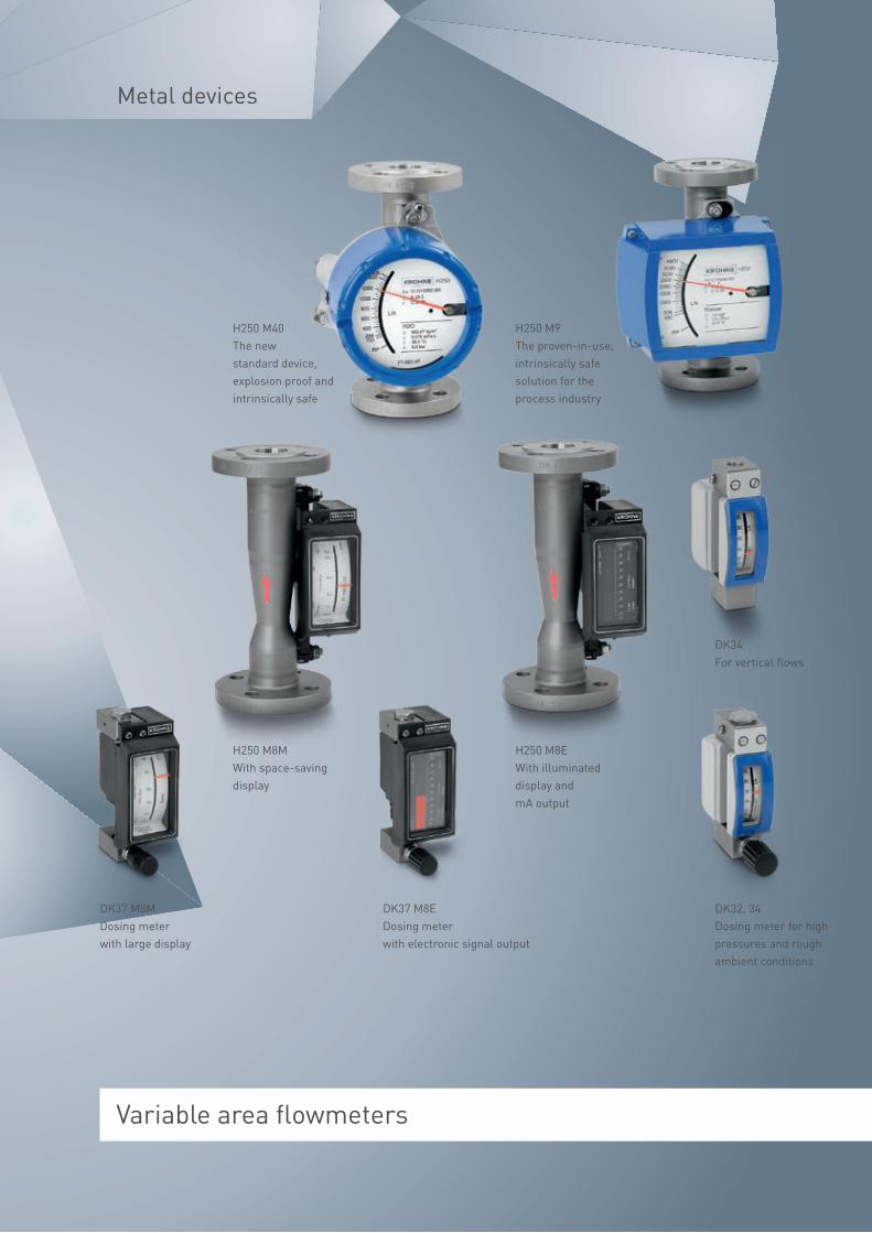
Metal devices
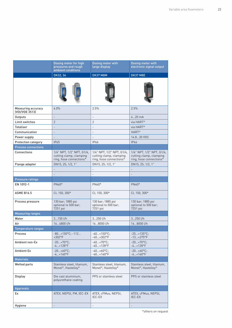
DK37 M8M Dosing meter with large display
H250 M8M With space-saving display
DK37 M8E Dosing meter with electronic signal output
H250 M8E With illuminated display and mA output
DK32, 34 Dosing meter for high pressures and rough ambient conditions
DK34 For vertical flows
H250 M9 The proven-in-use, intrinsically safe solution for the process industry
H250 M40 The new standard device, explosion proof and intrinsically safe

The measuring principle
Variable area flowmeters are suitable for the measuring of clean liquids and gases. They consist of upright conical tube made of metal, glass or plastic, in which a sophisticated float moves freely up and down. The flow goes through the tube, which is applied from the bottom to top, causes the float to rise until the forces are in equilibrium.
Three forces are acting on the float:• The buoyancy force B, which depends on the density of the medium and the volume of the float. • The gravity force G, which depends on the mass of the float. • The flow force F which depends on the float shape and the flow velocity through the variable area between float and tube.
Every flow rate corresponds to a defined variable area resulting from the conical shape of the measuring tube and the specific position of the float. With glass cones, the flow value can be read directly from a scale at the level of the float. With metal cones, the float position is transmitted to an indicator by magnetic means. There is no need for auxiliary power. Different measuring ranges are realised through variations in cone sizes and shapes and in selecting different float shapes and materials.
Variable area flowmeters
Diagram of VA40
Diagram of H250 M40
Highlights:
• Local indication without the need for auxiliary power
• Use in hazardous areas
• Accurate measurement even at very low flow rates (<0.5 l/h)
• Extended turndown ratio up to 100:1
• Suitable for low operating pressures
• Can be used even with short or no straight inlets/outlets
• Modular display and measuring transducer concept: easy component replacement
• World‘s only all-metal variable area flowmeter with EHEDG certification
• Flowmeters for nuclear power plants meet requirements of KTA 1401, RCC-E, RCC-M and ASME Section III and we are authorized to manufac-ture products with ASME N stamp and NPT stamp
• SIL2 certified
• Any meter orientation possible: vertical, horizontal or in fall pipes
• Optional limit switches, current output, totalizer, communication interfaces

21Variable area flowmeters
Since 1921, the name KROHNE has not only stood for innovative and reliable process measuring technology solutions, but also for exact, reliable and long-lasting variable area measuring technology.
Today, as the world’s market leader, we cover a variety of applications with our comprehensive product portfolio of metal, glass and plastic cones.
Typical applications include:
• Measurement and dosing of additives such as catalysts, surfactants, foam and corrosion inhibitors, caustic soda, chlorine or sulphur substances, etc.
• Inerting of tanks or containers • Measurement and dispensing of rinsing mediums (purge meters) • Sample feed measurement for analyser systems • Dosing and monitoring of lubricants and coolants for bearings and seals for process pumps and rotating machinery
• Hygienic applications in the food and pharmaceutical industries • Measurement of gases and chemicals in laboratories and test facilities • Gas/oil burner consumption measurement
For over 30 years, KROHNE has been a reliable partner for nuclear power plant operators and system builders. In this field, KROHNE meets the require-ments of KTA 1401, RCC-E, RCC-M and ASME Section III. This authorizes us to mark products with the N stamp and NPT stamp.
Maximum reliability when measuring liquids and gases – Since 1921
Industries:
• Chemical
• Petrochemical
• Mechanical and plant engineering
• Offshore plants
• Pharmaceutical
• Food and beverage
• Water and wastewater
• Power plants
Measuring the flow of CO2 in the inlet lines of the storage tanks in the beverage industry

22 Variable area flowmeters
Metal devices
With space-saving display
With illuminated display and mA output
The proven-in-use, intrinsically safe solution for the process industry
The new standard device, explosion proof and intrinsically safe
Dosing meter for high pressures and rough ambient conditions
Dosing meter with large display
Dosing meter with electronic signal output
H250 M8M H250 M8E H250 M9 H250 M40 DK32, 34 DK37 M8M DK37 M8E
Measuring accuracy (VDI/VDE 3513-2)
1.6% 1.6% 1.6% 1.6% Measuring accuracy (VDI/VDE 3513)
4.0% 2.5% 2.5%
Outputs - 4…20 mA 4…20 mA 4…20 mA Outputs - - 4…20 mA
Limit switches 2 via HART® 2 2 Limit switches 2 2 via HART®
Totaliser - via HART® 6 digit 8 digit, pulse output Totaliser - - via HART®
Communication - HART® HART®, PA HART®, FF, PA Communication - - HART®
Power supply - 14.8…30 VDC, (2-wire) 12…30 VDC, (2-wire) 14…30 VDC, (2-wire) Power supply - - 14.8…30 VDC
Protection category IP65 IP65 IP65, 67; NEMA4, 4X, 6 IP66, 68; NEMA4, 4X, 6 Protection category IP65 IP66 IP66
Process connections Process connections
EN 1092-1 DN15…25 DN15…25 DN15…150 DN15…150 Connections 1/4" NPT, 1/2" NPT, G1/4, cutting clamp, clamping ring, hose connections*
1/4" NPT, 1/2" NPT, G1/4, cutting clamp, clamping ring, hose connections*
1/4" NPT, 1/2" NPT, G1/4, cutting clamp, clamping ring, hose connections*
ASME B16.5 1/2…1" 1/2…1" 1/2…6" 1/2…6" Flange adapter DN15, 25; 1/2, 1" DN15, 25; 1/2, 1" DN15, 25; 1/2, 1"
Threaded 1/2…1" NPT, G1/2…G1 1/2…1" NPT, G1/2…G1 1/2…2" NPT, G1/2…G2 1/2…2" NPT, G1/2…G2 - - -
Special Clamp, aseptic Clamp, aseptic Clamp, aseptic Clamp, aseptic - - -
Pressure ratings Pressure ratings
EN 1092-1 PN16, 40, 63, 100, 160, 250*
PN16, 40, 63, 100, 160, 250*
PN16, 40, 63, 100, 160, 250*
PN16, 40, 63, 100, 160, 250*
EN 1092-1 PN40* PN40* PN40*
ASME B16.5 CL 150, 300, 600, 900, 1500*
CL 150, 300, 600, 900, 1500*
CL 150, 300, 600, 900, 1500*
CL 150, 300, 600, 900, 1500*
ASME B16.5 CL 150, 300* CL 150, 300* CL 150, 300*
Process pressure 0…400 bar; 0…5802 psi, optional to 3000 bar; 43511 psi
0…400 bar; 0…5802 psi, optional to 3000 bar; 43511 psi
0…400 bar; 0…5802 psi, optional to 3000 bar; 43511 psi
0…400 bar; 0…5802 psi, optional to 3000 bar; 43511 psi
Process pressure 130 bar; 1885 psi optional to 500 bar; 7251 psi
130 bar; 1885 psi optional to 500 bar; 7251 psi
130 bar; 1885 psi optional to 500 bar; 7251 psi
Measuring ranges Measuring ranges
Water 10…6300 l/h 10…6300 l/h 10…120000 l/h 10…120000 l/h Water 3…150 l/h 3…250 l/h 3…250 l/h
Air 0.7…220 m³/h 0.7…220 m³/h 0.7…2800 m3/h 0.7…2800 m3/h Air 16…4800 l/h 16…8000 l/h 16…8000 l/h
Temperature ranges Temperature ranges
Process -40…+200°C;-40…+362°F
-25…+200°C; -13…+362°F
-200…+300°C; -328…+572°F
-200…+300°C; -328…+572°F
Process -80…+150°C; -112…+302°F
-40…+150°C; -40…+302°F
-25…+135°C; -13…+275°F
Ambient non-Ex -40…+70°C; -40…+128°F
-20…+70°C; -4…+128°F
-40…+120°C; -40…+248°F
-40…+120°C; -40…+248°F
Ambient non-Ex -20…+70°C; -4…+128°F
-40…+70°C; -40…+128°F
-20…+70°C; -4…+128°F
Ambient Ex -40…+60°C; -40…+140°F
-20…+60°C; -4…+140°F
-40…+60°C; -40…+140°F
-40…+65°C;-40…+149°F
Ambient Ex -20…+60°C; -4…+140°F
-40…+60°C; -40…+140°F
-20…+60°C; -4…+140°F
Materials Materials
Wetted parts Stainless steel, Hastelloy®, titanium, Monel®, ceramic, PTFE
Stainless steel, Hastelloy®, titanium, Monel®, ceramic, PTFE
Stainless steel, Hastelloy®, titanium, Monel®, ceramic, PTFE
Stainless steel, Hastelloy®, titanium, Monel®, ceramic, PTFE
Wetted parts Stainless steel, titanium, Monel®, Hastelloy®
Stainless steel, titanium, Monel®, Hastelloy®
Stainless steel, titanium, Monel®, Hastelloy®
Display PPS or stainless steel PPS or stainless steel Die cast aluminium, polyurethane coating or stainless steel
Die cast aluminium, polyurethane coating or stainless steel
Display Die cast aluminium, polyurethane coating
PPS or stainless steel PPS or stainless steel
Approvals Approvals
Ex ATEX, NEPSI ATEX, NEPSI ATEX, NEPSI, FM ATEX, IEC-EX, cFMus,NEPSI , CCOE/PESO, KGS,EAC/GOST, INMETRO
Ex ATEX, NEPSI, FM, IEC-EX ATEX, cFMus, NEPSI, IEC-EX
ATEX, cFMus, NEPSI, IEC-EX
Hygiene EHEDG EHEDG EHEDG EHEDG Hygiene - - -
23Variable area flowmeters
With space-saving display
With illuminated display and mA output
The proven-in-use, intrinsically safe solution for the process industry
The new standard device, explosion proof and intrinsically safe
Dosing meter for high pressures and rough ambient conditions
Dosing meter with large display
Dosing meter with electronic signal output
H250 M8M H250 M8E H250 M9 H250 M40 DK32, 34 DK37 M8M DK37 M8E
Measuring accuracy (VDI/VDE 3513-2)
1.6% 1.6% 1.6% 1.6% Measuring accuracy (VDI/VDE 3513)
4.0% 2.5% 2.5%
Outputs - 4…20 mA 4…20 mA 4…20 mA Outputs - - 4…20 mA
Limit switches 2 via HART® 2 2 Limit switches 2 2 via HART®
Totaliser - via HART® 6 digit 8 digit, pulse output Totaliser - - via HART®
Communication - HART® HART®, PA HART®, FF, PA Communication - - HART®
Power supply - 14.8…30 VDC, (2-wire) 12…30 VDC, (2-wire) 14…30 VDC, (2-wire) Power supply - - 14.8…30 VDC
Protection category IP65 IP65 IP65, 67; NEMA4, 4X, 6 IP66, 68; NEMA4, 4X, 6 Protection category IP65 IP66 IP66
Process connections Process connections
EN 1092-1 DN15…25 DN15…25 DN15…150 DN15…150 Connections 1/4" NPT, 1/2" NPT, G1/4, cutting clamp, clamping ring, hose connections*
1/4" NPT, 1/2" NPT, G1/4, cutting clamp, clamping ring, hose connections*
1/4" NPT, 1/2" NPT, G1/4, cutting clamp, clamping ring, hose connections*
ASME B16.5 1/2…1" 1/2…1" 1/2…6" 1/2…6" Flange adapter DN15, 25; 1/2, 1" DN15, 25; 1/2, 1" DN15, 25; 1/2, 1"
Threaded 1/2…1" NPT, G1/2…G1 1/2…1" NPT, G1/2…G1 1/2…2" NPT, G1/2…G2 1/2…2" NPT, G1/2…G2 - - -
Special Clamp, aseptic Clamp, aseptic Clamp, aseptic Clamp, aseptic - - -
Pressure ratings Pressure ratings
EN 1092-1 PN16, 40, 63, 100, 160, 250*
PN16, 40, 63, 100, 160, 250*
PN16, 40, 63, 100, 160, 250*
PN16, 40, 63, 100, 160, 250*
EN 1092-1 PN40* PN40* PN40*
ASME B16.5 CL 150, 300, 600, 900, 1500*
CL 150, 300, 600, 900, 1500*
CL 150, 300, 600, 900, 1500*
CL 150, 300, 600, 900, 1500*
ASME B16.5 CL 150, 300* CL 150, 300* CL 150, 300*
Process pressure 0…400 bar; 0…5802 psi, optional to 3000 bar; 43511 psi
0…400 bar; 0…5802 psi, optional to 3000 bar; 43511 psi
0…400 bar; 0…5802 psi, optional to 3000 bar; 43511 psi
0…400 bar; 0…5802 psi, optional to 3000 bar; 43511 psi
Process pressure 130 bar; 1885 psi optional to 500 bar; 7251 psi
130 bar; 1885 psi optional to 500 bar; 7251 psi
130 bar; 1885 psi optional to 500 bar; 7251 psi
Measuring ranges Measuring ranges
Water 10…6300 l/h 10…6300 l/h 10…120000 l/h 10…120000 l/h Water 3…150 l/h 3…250 l/h 3…250 l/h
Air 0.7…220 m³/h 0.7…220 m³/h 0.7…2800 m3/h 0.7…2800 m3/h Air 16…4800 l/h 16…8000 l/h 16…8000 l/h
Temperature ranges Temperature ranges
Process -40…+200°C;-40…+362°F
-25…+200°C; -13…+362°F
-200…+300°C; -328…+572°F
-200…+300°C; -328…+572°F
Process -80…+150°C; -112…+302°F
-40…+150°C; -40…+302°F
-25…+135°C; -13…+275°F
Ambient non-Ex -40…+70°C; -40…+128°F
-20…+70°C; -4…+128°F
-40…+120°C; -40…+248°F
-40…+120°C; -40…+248°F
Ambient non-Ex -20…+70°C; -4…+128°F
-40…+70°C; -40…+128°F
-20…+70°C; -4…+128°F
Ambient Ex -40…+60°C; -40…+140°F
-20…+60°C; -4…+140°F
-40…+60°C; -40…+140°F
-40…+65°C;-40…+149°F
Ambient Ex -20…+60°C; -4…+140°F
-40…+60°C; -40…+140°F
-20…+60°C; -4…+140°F
Materials Materials
Wetted parts Stainless steel, Hastelloy®, titanium, Monel®, ceramic, PTFE
Stainless steel, Hastelloy®, titanium, Monel®, ceramic, PTFE
Stainless steel, Hastelloy®, titanium, Monel®, ceramic, PTFE
Stainless steel, Hastelloy®, titanium, Monel®, ceramic, PTFE
Wetted parts Stainless steel, titanium, Monel®, Hastelloy®
Stainless steel, titanium, Monel®, Hastelloy®
Stainless steel, titanium, Monel®, Hastelloy®
Display PPS or stainless steel PPS or stainless steel Die cast aluminium, polyurethane coating or stainless steel
Die cast aluminium, polyurethane coating or stainless steel
Display Die cast aluminium, polyurethane coating
PPS or stainless steel PPS or stainless steel
Approvals Approvals
Ex ATEX, NEPSI ATEX, NEPSI ATEX, NEPSI, FM ATEX, IEC-EX, cFMus,NEPSI , CCOE/PESO, KGS,EAC/GOST, INMETRO
Ex ATEX, NEPSI, FM, IEC-EX ATEX, cFMus, NEPSI, IEC-EX
ATEX, cFMus, NEPSI, IEC-EX
Hygiene EHEDG EHEDG EHEDG EHEDG Hygiene - - -
*others on request

24 Variable area flowmeters
Glass devices
*others on request
Small and compact dosing meters with valve
The cost-effective version for the analytical field
All-purpose flowmeter with various process connections
For measuring gases with low operating pressures
For maximum safety requirements
The cost-effective plastic alternative
DK46, 47, 48, 800 DK700 VA40 VA45 GA24 K20
Measuring accuracy (VDI/VDE 3513)
1.0%; 2.5%; 4.0% 4.0%; 6.0% 1.0% Measuring accuracy (VDI/VDE 3513)
2.5% 1.0% ±2.5% full scale
Outputs - - 4…20 mA Outputs - - -
Limit switches 2 - 2 Limit switches - 2 -
Totaliser - - - Totaliser - - -
Communication - - - Communication - - -
Power supply - - 14…30 VDC (2-wire) Power supply - - -
Protection category IP65 - IP67 Protection category - - -
Process connections Process connections
Connections 1/4" NPT, G1/4, cutting clamp, clamping ring, hose connections*
G1/8, hose connections Threaded, flange, hose connections, hygienic design
Connections Threaded, flange, hose connections
Flange DN15..50; ASME1/2…2"
Threaded G1/2…2
Pressure ratings Pressure ratings
EN 1092-1 - - PN40 EN 1092-1 - PN40 -
ASME B16.5 - - CL 150 ASME B16.5 - CL 150 -
Process pressure 0…10 bar; 0…145 psi 0…4 bar; 0…58 psi 0…10 bar; 0…145 psi Process pressure 1 bar; 14.5 psi 7…10 bar; 102…145 psi 0…6 bar; 0…72 psi
Measuring ranges Measuring ranges
Water 0.4…160 l/h 0.25…40 l/h 0.4…10000 l/h Water - 0.4…10000 l/h 0.65…25000 l/h
Air 0.5…5000 l/h 0.5…1000 l/h 0.007…310 m3/h Air 150…60000 l/h 0.007…310 m3/h -
Temperature ranges Temperature ranges
Process -5…+100°C; -23…+212°F -5…+100°C; -23…+212°F -20…+100°C; -4…+212°F Process -20…+100°C; -4…+212°F -40…+120°C; -40…+248°F -20…+100°C; -4…+212°F
Ambient non-Ex -20…+100°C; -4…+212°F -20…+100°C; -4…+212°F -20…+100°C; -4…+212°F Ambient non-Ex -20…+100°C; -4…+212°F -20…+100°C; -4…+212°F -20…+100°C; -4…+212°F
Ambient Ex -20…+70°C; -4…+128°F -20…+85°C; -4…+185°F Ambient Ex - - -
Materials Materials
Measuring cone Borosilicate glass Borosilicate glass Borosilicate glass Measuring cone Borosilicate glass Borosilicate glass Polysulphone
Process connection Stainless steel, brass, PVDF PVDF Stainless steel, PVDF Process connection Stainless steel Steel plate galvanised and coated
Polysulphone
Approvals Approvals
Ex ATEX, NEPSI - ATEX Ex - ATEX -
Hygiene - - - Hygiene - - -

25Variable area flowmeters
Small and compact dosing meters with valve
The cost-effective version for the analytical field
All-purpose flowmeter with various process connections
For measuring gases with low operating pressures
For maximum safety requirements
The cost-effective plastic alternative
DK46, 47, 48, 800 DK700 VA40 VA45 GA24 K20
Measuring accuracy (VDI/VDE 3513)
1.0%; 2.5%; 4.0% 4.0%; 6.0% 1.0% Measuring accuracy (VDI/VDE 3513)
2.5% 1.0% ±2.5% full scale
Outputs - - 4…20 mA Outputs - - -
Limit switches 2 - 2 Limit switches - 2 -
Totaliser - - - Totaliser - - -
Communication - - - Communication - - -
Power supply - - 14…30 VDC (2-wire) Power supply - - -
Protection category IP65 - IP67 Protection category - - -
Process connections Process connections
Connections 1/4" NPT, G1/4, cutting clamp, clamping ring, hose connections*
G1/8, hose connections Threaded, flange, hose connections, hygienic design
Connections Threaded, flange, hose connections
Flange DN15..50; ASME1/2…2"
Threaded G1/2…2
Pressure ratings Pressure ratings
EN 1092-1 - - PN40 EN 1092-1 - PN40 -
ASME B16.5 - - CL 150 ASME B16.5 - CL 150 -
Process pressure 0…10 bar; 0…145 psi 0…4 bar; 0…58 psi 0…10 bar; 0…145 psi Process pressure 1 bar; 14.5 psi 7…10 bar; 102…145 psi 0…6 bar; 0…72 psi
Measuring ranges Measuring ranges
Water 0.4…160 l/h 0.25…40 l/h 0.4…10000 l/h Water - 0.4…10000 l/h 0.65…25000 l/h
Air 0.5…5000 l/h 0.5…1000 l/h 0.007…310 m3/h Air 150…60000 l/h 0.007…310 m3/h -
Temperature ranges Temperature ranges
Process -5…+100°C; -23…+212°F -5…+100°C; -23…+212°F -20…+100°C; -4…+212°F Process -20…+100°C; -4…+212°F -40…+120°C; -40…+248°F -20…+100°C; -4…+212°F
Ambient non-Ex -20…+100°C; -4…+212°F -20…+100°C; -4…+212°F -20…+100°C; -4…+212°F Ambient non-Ex -20…+100°C; -4…+212°F -20…+100°C; -4…+212°F -20…+100°C; -4…+212°F
Ambient Ex -20…+70°C; -4…+128°F -20…+85°C; -4…+185°F Ambient Ex - - -
Materials Materials
Measuring cone Borosilicate glass Borosilicate glass Borosilicate glass Measuring cone Borosilicate glass Borosilicate glass Polysulphone
Process connection Stainless steel, brass, PVDF PVDF Stainless steel, PVDF Process connection Stainless steel Steel plate galvanised and coated
Polysulphone
Approvals Approvals
Ex ATEX, NEPSI - ATEX Ex - ATEX -
Hygiene - - - Hygiene - - -

UFM 3030 3-beam device for use in custody transfer heat measurement in district heating
OPTISONIC 3400 Universal 3-beam device for inline measurement of liquids
OPTISONIC 7300 Universal 2-beam device for inline measurement of process gases
UFM 530 HT Rugged 2-beam high-temperature device for extreme process conditions
OPTISONIC 6300 Flexible clamp-on device with industrial clamp-on mechanism
OPTISONIC 6300 P Battery-powered portable clamp-on device
Process measuring technology
OPTISONIC 8300 2-beam ultrasonic flowmeter for superheated steam
Ultrasonic flowmeters
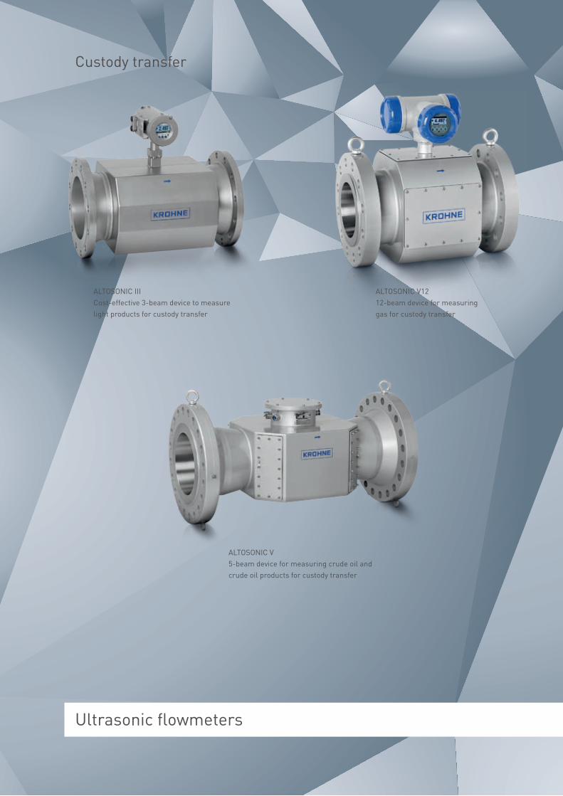
ALTOSONIC III Cost-effective 3-beam device to measure light products for custody transfer
ALTOSONIC V5-beam device for measuring crude oil and crude oil products for custody transfer
ALTOSONIC V12 12-beam device for measuring gas for custody transfer
Custody transfer

28 Ultrasonic flowmeters
UFC 300 W

29Ultrasonic flowmeters
Ultrasonic clamp-on flowmeters: no training, no special tools, no open issues
Whether it’s installation, commissioning, calibration or maintenance, KROHNE is the first manufacturer of ultrasonic clamp-on flowmeters to comprehensively deal with and redefine the topic of user-friendliness.
For the OPTISONIC 6300 ultrasonic flowmeter, for example, it takes just 15 minutes from installation to complete commissioning of the device.
This is due not only to the simple installa-tion using patented clamping devices requiring no special tools but also to the signal measuring transducers pre-in-stalled on the rail at the factory.
User-friendliness redefined
And commissioning the OPTISONIC 6300 is as simple as it is safe. After being switched on for the first time, the elec-tronic unit carries out an automatic self test. The preset parameters cover 90 % of all applications.
An intelligent installation assistant now guides the user step by step through the program – and simultaneously provides support during optimisation of the flow measurement.

30 Ultrasonic flowmeters
The measuring principle
KROHNE ultrasonic flowmeters are based on the time-of-flight method. This method consists of two diagonally opposed ultra-sonic sensors which function alternately as transmitters and receivers. The sound signal alternately emitted from both is at once accelerated by the flow and slowed down against the flow. The difference in the time the signal requires to travel the measured sections is directly proportional to the mean flow rate from which the volumetric flow can then be calculated. Through the use of several ultrasonic paths, flow profile aberrations can be compensated.
Ultrasonic flowmeters
Highlights:
• Complete portfolio for liquid, gas and steam applications
• Accuracy and reproducibility regard-less of medium properties such as viscosity, temperature, density and electrical conductivity
• Diagnostic and compensation functions for disturbed flow profiles and deposits
• No moving parts or components that protrude into the measuring tube
• Low operating and maintenance costs due to non-wearing parts
• Excellent long-term stability, no recalibration required
• High degree of reliability thanks to redundant measuring paths
• High-temperature versions available
• Large dynamic range
• Bi-directional flow measurement
Transducer A
Transducer B
Flow velocity
Transit time 95.4949 µs from A to B
Transit time 95.5862 µs from B to A
Differential time Delta 91.29 ns

Whether liquid or gaseous, aggressive or corrosive: KROHNE ultrasonic flowmeters measure a wide range of media.
In 1997, KROHNE introduced the ALTOSONIC V, the first high precision, calibratable ultrasonic flowmeter for the petroleum industry. The ALTOSONIC V’s five measuring paths can perform extremely precise and reproducible measurements regardless of the viscosity of the medium – a real quantum leap.
As the world’s leader in the field of ultrasonic inline flowmeters, our devices are at home in a wide range of industries. Whether it’s measuring cooling water and demineralized water in power plants, controlling dosing and mixing processes in the chemical industry or measuring liquid hydrocarbons in the oil and gas industry, you can put your absolute trust in KROHNE ultrasonic flowmeters in any situation.
Standard in the process industry: Benchmark for custody transfer
Industries:
• Oil and gas
• Petrochemical
• Chemical
• Cold and hot water
• Heating, Ventilation and Air Conditioning (HVAC)
• Power plants
• Semi-conductors

32 Ultrasonic flowmeters
Process measurement
Universal 3-beam device for inline mea- surement of liquids
Universal 2-beam device for inline measurement of process gases
2-beam ultrasonic flowmeter for superheated steam
3-beam device for use in custody transfer heat measurement in district heating
Rugged 2-beam high- temperature device for extreme process conditions
Flexible clamp-on device with industrial clamp-on mechanism
Battery-powered portable clamp-on device
Cost-effective 3-beam device to measure light products for custody transfer
12-beam device for measuring of gases for custody transfer
5-beam device for measuring crude oil and crude oil products for custody transfer
OPTISONIC 3400 OPTISONIC 7300 OPTISONIC 8300 UFM 3030 UFM 530 HT OPTISONIC 6300 OPTISONIC 6300 P ALTOSONIC III ALTOSONIC V12 ALTOSONIC V
Signal converter UFC 400 GFC 300 UFC 300 UFC 030 UFC 030 UFC 300 UFC 300 P UFC III GFC V12 UFC-V / UFP-V
Measuring accuracy
Volume flow: DN100; 4": < ± 1.5% of measured value, DN150…600; 6…24": < ± 1% of measured value
Air calibration (atmospheric): 2…3": ±1.5%; 4…24": ±1%
Super heated steams (>±15°C; +59°F super-heat), high temperature gases
±0.5% of measured value
±1.0% of measured value
±1.0% of measured value ±1.0% of measured value ±0.2% of measured value for 20.000<RE<50.000; 0.15% of measured value for RE>50.000
±0.2% of measured value, ±0.1% after linearisation
±0.15% of measured value, turndown ratio 1:10; ±0.20% of measured value, turndown ratio 1:50
Process conditions
Liquids with max. 5% solid content and max. 2% gas content
Process gases Super heated steams (>±15°C; +59°F super-heat), high temperature gases
Liquids with max. 5% solid content and max. 2% gas content
Liquids with max. 5% solid content and max. 2% gas content
Liquids with max. 5% solid content and max. 2% gas content
Liquids with max. 5% solid content and max. 2% gas content
Single-hydrocarbons Natural gas Multi-hydrocarbons, viscosity 0.1…1500 cSt
Outputs Current, pulse, status Current, pulse, status Current, pulse, status Current, pulse, status Current, pulse, status Current, pulse, status Current, pulse, status Current, pulse, status 4 x digital 4 x digital, 1 x analogue
Inputs Binary, mA (temp., pressure)
2 x 4…20 mA, active, binary
Binary, mA(temp., pressure)
Binary, mA (temp., pressure)
Binary, mA (temp., pressure)
Binary 2 x 0(4)…20 mA - Binary 6 x digital, 16 x analogue
Communication HART®, PROFIBUS®, FF, Modbus
HART®, Modbus, FF HART®, Modbus, FF HART® HART® HART® USB slave - Modbus 2 x RS485 Modbus RS422/485
Power supply 100…240 VAC; 24 VAC/DC
85…250 VAC; 11…31 VDC; 20.5…26 VAC/DC
100…230 VAC;24 VAC/DC
100…240 VAC; 24 VAC/DC
100…240 VAC; 24 VAC/DC
85…250 VAC; 20.5…26 VAC/DC
Battery power 100…240 VAC; 24 VAC/DC
24 VDC 100…240 VAC; 24 VAC/DC
Protection category: Compact (C) Field (F) Wall (W)
IP67; NEMA6 IP65; NEMA4, 4X -
- IP66, 67; NEMA4, 4X, 6 IP65; NEMA4, 4X
-IP65; NEMA4X/6-
IP67; NEMA6 IP65; NEMA4, 4X -
-IP65, NEMA4, 4X-
- IP66, 67; NEMA4, 4X, 6 IP65; NEMA4, 4X
- IP65, NEMA4 -
IP67; NEMA6 - -
IP66--
IP65, 67; NEMA4, 6 - -
Measuring sensor OPTISONIC 3000 OPTISONIC 7000 OPTISONIC 8000 UFS 3000 UFS 500 HT OPTISONIC 6000 OPTISONIC 6000 ALTOSONIC III ALTOSONIC V12 ALTOSONIC V
Process connections
EN 1092-1 DN25…3000; PN10…100
DN50…600; PN10, 16, 40
DN100…600; PN16…160 or flangeless
DN25…3000; PN10…100
DN25…80, 100…150, 200…300; PN10, 16, 40
DN15…4000 DN15…4000 - - -
ASME B16.5 1…120"; CL 150…1500 2…24"; CL 150…900 4…24"; CL 150…2500 or flangeless
1…120"; CL 150…1500 1…12"; CL 150 1/2…160" 1/2…160" 2…40"; CL 150…1500 4…64"; Cl 150…2500 4…40"; CL 150…1500
Temperature ranges
Process -200…+250°C; -328…+482°F
-40…+180°C; -40…+356°F
-25…+540°C; -13…+1004°F, higher on request
-25…+180°C; -13…+356°F
-25…+500ºC; -13…+932ºF
-40…+200°C; -40…+392°F
-40…+200°C; -40…+392°F
-200…+250°C; -328…+428°F
-40…+100°C; -40…+212°F
-200…+250°C; -328…+428°F
Ambient (incl. converter)
-40…+65°C; -40…+149°F
-40…+65°C; -40…+149°F
-40…+65°C; -40…+149°F
-40…+65°C; -40…+149°F
-40…+65ºC; -40…+149ºF
-40…+60°C; -40…+140°F
-20…+55°C; -4…+131°F
-40…+70°C; -13…+149°F
-40…+65°C; -40…+149°F
-55…+60°C; -67…+140°F
Materials
Measuring tube, flange
Steel, stainless steel, Hastelloy® C4, duplex
Steel, stainless steel, Hastelloy® C, duplex
Carbon steel, high temperature steel on request
Steel, stainless steel Stainless steel, steel, duplex, Inconel®
Sensor in aluminium, stainless steel
Sensor in aluminum Stainless steel LT carbon steel, stainless steel and duplex optional
Steel, stainless steel, Hastelloy® C4, duplex
Protection category
Measuring sensor IP65, 67, 68; NEMA4, 4X, 6, 6P
IP67; NEMA6 IP67; NEMA6 IP65, 67, 68; NEMA4, 4X, 6, 6P
IP65; NEMA4, 4X IP67; NEMA6 IP67; NEMA6 IP67; NEMA6 IP66 IP65, 67; NEMA4, 6
Approvals
Ex ATEX, IEC-EX, FM, CSA, NEPSI
ATEX, NEPSI, (FM, CSA pending)
ATEX, IEC, NEPSI ATEX, FM, CSA, NEPSI ATEX, FM, CSA ATEX, FM, CSA, NEPSI - ATEX, FM, CSA, IECEx ATEX, FM, CSA, IECEx ATEX, FM, CSA,
Custody transfer - - - MID MI-004 - - - MID MI-005, Gosstandard, OIML R-117-1 class 0.3, API
OIML R137 class 0.5, MID, AGA 9, ISO 17089
MID MI-005, Gosstandard, OIML R-117-1 class 0.3, API

33Ultrasonic flowmeters
Custody transfer
Universal 3-beam device for inline mea- surement of liquids
Universal 2-beam device for inline measurement of process gases
2-beam ultrasonic flowmeter for superheated steam
3-beam device for use in custody transfer heat measurement in district heating
Rugged 2-beam high- temperature device for extreme process conditions
Flexible clamp-on device with industrial clamp-on mechanism
Battery-powered portable clamp-on device
Cost-effective 3-beam device to measure light products for custody transfer
12-beam device for measuring of gases for custody transfer
5-beam device for measuring crude oil and crude oil products for custody transfer
OPTISONIC 3400 OPTISONIC 7300 OPTISONIC 8300 UFM 3030 UFM 530 HT OPTISONIC 6300 OPTISONIC 6300 P ALTOSONIC III ALTOSONIC V12 ALTOSONIC V
Signal converter UFC 400 GFC 300 UFC 300 UFC 030 UFC 030 UFC 300 UFC 300 P UFC III GFC V12 UFC-V / UFP-V
Measuring accuracy
Volume flow: DN100; 4": < ± 1.5% of measured value, DN150…600; 6…24": < ± 1% of measured value
Air calibration (atmospheric): 2…3": ±1.5%; 4…24": ±1%
Super heated steams (>±15°C; +59°F super-heat), high temperature gases
±0.5% of measured value
±1.0% of measured value
±1.0% of measured value ±1.0% of measured value ±0.2% of measured value for 20.000<RE<50.000; 0.15% of measured value for RE>50.000
±0.2% of measured value, ±0.1% after linearisation
±0.15% of measured value, turndown ratio 1:10; ±0.20% of measured value, turndown ratio 1:50
Process conditions
Liquids with max. 5% solid content and max. 2% gas content
Process gases Super heated steams (>±15°C; +59°F super-heat), high temperature gases
Liquids with max. 5% solid content and max. 2% gas content
Liquids with max. 5% solid content and max. 2% gas content
Liquids with max. 5% solid content and max. 2% gas content
Liquids with max. 5% solid content and max. 2% gas content
Single-hydrocarbons Natural gas Multi-hydrocarbons, viscosity 0.1…1500 cSt
Outputs Current, pulse, status Current, pulse, status Current, pulse, status Current, pulse, status Current, pulse, status Current, pulse, status Current, pulse, status Current, pulse, status 4 x digital 4 x digital, 1 x analogue
Inputs Binary, mA (temp., pressure)
2 x 4…20 mA, active, binary
Binary, mA(temp., pressure)
Binary, mA (temp., pressure)
Binary, mA (temp., pressure)
Binary 2 x 0(4)…20 mA - Binary 6 x digital, 16 x analogue
Communication HART®, PROFIBUS®, FF, Modbus
HART®, Modbus, FF HART®, Modbus, FF HART® HART® HART® USB slave - Modbus 2 x RS485 Modbus RS422/485
Power supply 100…240 VAC; 24 VAC/DC
85…250 VAC; 11…31 VDC; 20.5…26 VAC/DC
100…230 VAC;24 VAC/DC
100…240 VAC; 24 VAC/DC
100…240 VAC; 24 VAC/DC
85…250 VAC; 20.5…26 VAC/DC
Battery power 100…240 VAC; 24 VAC/DC
24 VDC 100…240 VAC; 24 VAC/DC
Protection category: Compact (C) Field (F) Wall (W)
IP67; NEMA6 IP65; NEMA4, 4X -
- IP66, 67; NEMA4, 4X, 6 IP65; NEMA4, 4X
-IP65; NEMA4X/6-
IP67; NEMA6 IP65; NEMA4, 4X -
-IP65, NEMA4, 4X-
- IP66, 67; NEMA4, 4X, 6 IP65; NEMA4, 4X
- IP65, NEMA4 -
IP67; NEMA6 - -
IP66--
IP65, 67; NEMA4, 6 - -
Measuring sensor OPTISONIC 3000 OPTISONIC 7000 OPTISONIC 8000 UFS 3000 UFS 500 HT OPTISONIC 6000 OPTISONIC 6000 ALTOSONIC III ALTOSONIC V12 ALTOSONIC V
Process connections
EN 1092-1 DN25…3000; PN10…100
DN50…600; PN10, 16, 40
DN100…600; PN16…160 or flangeless
DN25…3000; PN10…100
DN25…80, 100…150, 200…300; PN10, 16, 40
DN15…4000 DN15…4000 - - -
ASME B16.5 1…120"; CL 150…1500 2…24"; CL 150…900 4…24"; CL 150…2500 or flangeless
1…120"; CL 150…1500 1…12"; CL 150 1/2…160" 1/2…160" 2…40"; CL 150…1500 4…64"; Cl 150…2500 4…40"; CL 150…1500
Temperature ranges
Process -200…+250°C; -328…+482°F
-40…+180°C; -40…+356°F
-25…+540°C; -13…+1004°F, higher on request
-25…+180°C; -13…+356°F
-25…+500ºC; -13…+932ºF
-40…+200°C; -40…+392°F
-40…+200°C; -40…+392°F
-200…+250°C; -328…+428°F
-40…+100°C; -40…+212°F
-200…+250°C; -328…+428°F
Ambient (incl. converter)
-40…+65°C; -40…+149°F
-40…+65°C; -40…+149°F
-40…+65°C; -40…+149°F
-40…+65°C; -40…+149°F
-40…+65ºC; -40…+149ºF
-40…+60°C; -40…+140°F
-20…+55°C; -4…+131°F
-40…+70°C; -13…+149°F
-40…+65°C; -40…+149°F
-55…+60°C; -67…+140°F
Materials
Measuring tube, flange
Steel, stainless steel, Hastelloy® C4, duplex
Steel, stainless steel, Hastelloy® C, duplex
Carbon steel, high temperature steel on request
Steel, stainless steel Stainless steel, steel, duplex, Inconel®
Sensor in aluminium, stainless steel
Sensor in aluminum Stainless steel LT carbon steel, stainless steel and duplex optional
Steel, stainless steel, Hastelloy® C4, duplex
Protection category
Measuring sensor IP65, 67, 68; NEMA4, 4X, 6, 6P
IP67; NEMA6 IP67; NEMA6 IP65, 67, 68; NEMA4, 4X, 6, 6P
IP65; NEMA4, 4X IP67; NEMA6 IP67; NEMA6 IP67; NEMA6 IP66 IP65, 67; NEMA4, 6
Approvals
Ex ATEX, IEC-EX, FM, CSA, NEPSI
ATEX, NEPSI, (FM, CSA pending)
ATEX, IEC, NEPSI ATEX, FM, CSA, NEPSI ATEX, FM, CSA ATEX, FM, CSA, NEPSI - ATEX, FM, CSA, IECEx ATEX, FM, CSA, IECEx ATEX, FM, CSA,
Custody transfer - - - MID MI-004 - - - MID MI-005, Gosstandard, OIML R-117-1 class 0.3, API
OIML R137 class 0.5, MID, AGA 9, ISO 17089
MID MI-005, Gosstandard, OIML R-117-1 class 0.3, API

MFC 300 R Rack-mounted
OPTIMASS 3000 Suitable for extremely low flow rates
OPTIMASS 7000 High-end solution featuring a single straight measuring tube
OPTIMASS 1000 The standard device with an excellent price-performance ratio
MFC 300 W Wall-mounted
MFC 300 F/MFC 400 F Field housing
MFC 300 C/MFC 400 C General purpose
OPTIMASS 2000 The first choice for bulk flows for custody transfer
The modular product line
Flow sensors
Converters

Mass flowmeters
The specialists
OPTIGAS 4010 Specially designed for CNG in dispensing systems
OPTIMASS 6000 The standard high-performance meter with Entrained Gas ManagementTM for the process industry
OPTIBATCH 4011 Specially designed for linear and rotating filling machines

36 Mass flowmeters
When it comes to selecting a flowmeter for your application, the OPTIMASS range covers all bases. Our engineers have developed a family of meters from small to large, for high pressure, cryogenic temperatures and high temperatures.
All meters have been designed to reduce constraints on the user with regards to installation – simply follow good engineering practice to obtain the desired results. Another highlight is the diagnostics platform, which is unique in this class of device. It not only monitors the device itself but also the process environment.
Within the system, the diagnostics software monitors the process temperature and a series of auxiliary values such as the driver energy, in order to ultimately confirm the condition of the process medium. OPTIMASS can even generate intelligent warning messages when a certain proportion of gas bubbles or solids is exceeded, providing valuable information about the process itself.
Mass flowmeters: A solution for all process applications

The measuring principle
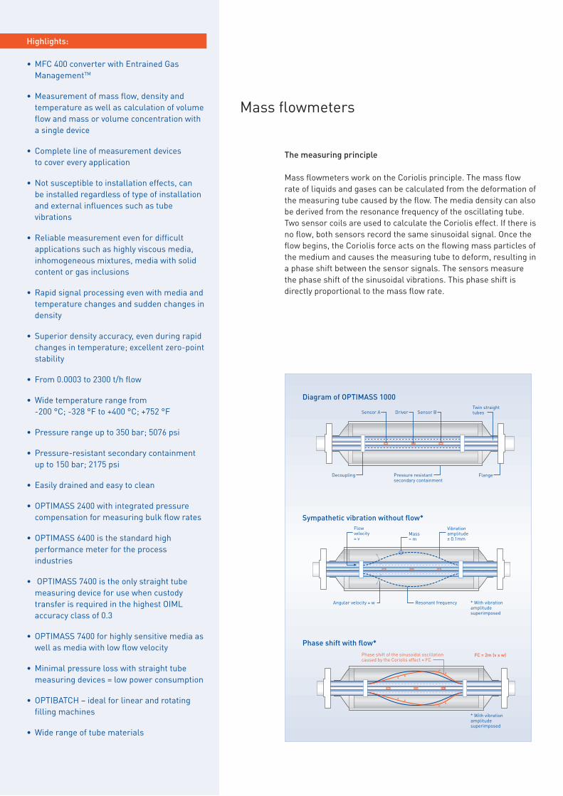
Mass flowmeters work on the Coriolis principle. The mass flow rate of liquids and gases can be calculated from the deformation of the measuring tube caused by the flow. The media density can also be derived from the resonance frequency of the oscillating tube. Two sensor coils are used to calculate the Coriolis effect. If there is no flow, both sensors record the same sinusoidal signal. Once the flow begins, the Coriolis force acts on the flowing mass particles of the medium and causes the measuring tube to deform, resulting in a phase shift between the sensor signals. The sensors measure the phase shift of the sinusoidal vibrations. This phase shift is directly proportional to the mass flow rate.
Mass flowmeters
Highlights:
• MFC 400 converter with Entrained Gas ManagementTM
• Measurement of mass flow, density and temperature as well as calculation of volume flow and mass or volume concentration with a single device
• Complete line of measurement devices to cover every application
• Not susceptible to installation effects, can be installed regardless of type of installation and external influences such as tube vibrations
• Reliable measurement even for difficult applications such as highly viscous media, inhomogeneous mixtures, media with solid content or gas inclusions
• Rapid signal processing even with media and temperature changes and sudden changes in density
• Superior density accuracy, even during rapid changes in temperature; excellent zero-point stability
• From 0.0003 to 2300 t/h flow
• Wide temperature range from -200 °C; -328 °F to +400 °C; +752 °F
• Pressure range up to 350 bar; 5076 psi
• Pressure-resistant secondary containment up to 150 bar; 2175 psi
• Easily drained and easy to clean
• OPTIMASS 2400 with integrated pressure compensation for measuring bulk flow rates
• OPTIMASS 6400 is the standard high performance meter for the process industries
• OPTIMASS 7400 is the only straight tube measuring device for use when custody transfer is required in the highest OIML accuracy class of 0.3
• OPTIMASS 7400 for highly sensitive media as well as media with low flow velocity
• Minimal pressure loss with straight tube measuring devices = low power consumption
• OPTIBATCH – ideal for linear and rotating filling machines
• Wide range of tube materials
Diagram of OPTIMASS 1000
Sensor A Sensor B
Flange
DriverTwin straight tubes
Decoupling
Flow velocity = v
Mass = m
Vibration amplitude ± 0.1mm
Angular velocity = w Resonant frequency * With vibration amplitude superimposed
* With vibration amplitude superimposed
Phase shift of the sinusoidal oscillation caused by the Coriolis effect = FC
FC = 2m (v x w)
Pressure resistant secondary containment
Sympathetic vibration without flow*
Phase shift with flow*

39Mass flowmeters
Just how accurate and reliable a mass flowmeter actually is becomes obvious when constant parame-ters such as medium, temperature or pressure undergo sudden changes. The OPTIMASS series from KROHNE sets the standard. With high performance straight and bent tube designs.
KROHNE offers superior straight and bent tube design mass flowmeters, so the customer now can choose the best meter for their application. We offer a unique straight tube design for minimal pressure drop, highly viscous and slurry applications. The superior bent tube design is suitable for cryogenic, high temperature applications and extremely high pressures.
The MFC 400 converter offers excellent zero stability, advanced density and concentration measurement and a high performance with air entrainment. With new Entrained Gas ManagementTM the meter is now able to measure from 0 % to 100 % gas entrainment.
Superior performance – Even with quick temperature and media changes
Industries:
• Chemical
• Pharmaceutical
• Food and beverage
• Oil and gas
• Petrochemical
• Pulp and paper
• Mining and minerals
• Power plants
• Water and wastewater
• Marine
OPTIMASS 2400 – Minimal installation footprint

OPTIMASS 2000 + MFC 400
OPTIMASS 2000
OPTIMASS 1000 + MFC 400 OPTIMASS 3000 + MFC 400
OPTIMASS 3000
40 Mass flowmeters
The modular product line
The standard device with an excellent price-performance ratio
First choice for bulk flow and liquid custody transfer
Suitable for extremely low flow rates
The standard high-performance meter with Entrained Gas Manage- mentTM for the process industry
High-end solution featuring a straight single measuring tube
Specially designed for linear and rotating filling machines
Specially designed for CNG in dispensing systems
OPTIMASS 1010 OPTIMASS 2000 OPTIMASS 3010 OPTIMASS 7010 OPTIBATCH 4011 OPTIGAS 4010Measuring accuracy Liquid: ±0.15%
gas: 0.35% density: ±2 kg/m3
Liquid: ±0.1% gas: 0.35% density: ±2 kg/m3 (±0.5 kg/m3)
Liquid: ±0.1% gas: ±0.5% density: ±2 kg/m3 (±0.5 kg/m3)
- Liquid: ±0.1% gas: 0.35% density: ±2 kg/m3 (±0.5 kg/m3)
Liquid: mass: ±0.15% volume: ±0.2%
Liquid: ±0.5% per batch gas: ±0.5% per batch
Communication Modbus Modbus Modbus - Modbus Modbus (configuration) ModbusPower supply 12 VDC 12 VDC 12 VDC - 12 VDC 24 VDC 12 VDCProtection category IP67; NEMA4X IP67; NEMA4X IP67; NEMA4X - IP67; NEMA4X IP67; NEMA6 IP67; NEMA4X
OPTIMASS 1400 OPTIMASS 2400 OPTIMASS 3400 OPTIMASS 6400 OPTIMASS 7400 OPTIBATCH 4011 OPTIGAS 4010
Measuring accuracy Liquid: ±0.15% gas: 0.35% density: ±2 kg/m3
Liquid: ≤0.1% (optional: ±0.05%)gas: ≤0.35%density: ±1 kg/m3 (±0.2 kg/m3)
Liquid: ±0.1% gas: ±0.5% density: ±2 kg/m3 (±0.5 kg/m3)
Liquid: ±0.1%, ±0.05% optional gas: 0.35% density: ±1 kg/m3 (±0.2 kg/m3)
Liquid: ±0.1% gas: 0.35% density: ±2 kg/m3 (±0.5 kg/m3)
Liquid: mass: ±0.15% volume: ±0.2%
Liquid: ±0.5% per batch gas: ±0.5% per batch
Outputs Current, pulse/frequency, status Current, pulse/frequency, status Current, pulse/frequency, status Current, pulse/frequency, status Current, pulse/frequency, status Pulse/frequency -Inputs Binary Binary Binary Binary Binary - -Communication HART®, FF, PA, DP, Modbus HART®, FF, PA, DP, Modbus HART®, FF, PA, DP, Modbus HART®, FF, PA, DP, Modbus HART®, FF, PA, DP, Modbus Modbus (configuration) ModbusPower supply 85…250 VAC; 11…31 VDC;
20.5…26 VAC/DC85…250 VAC; 11…31 VDC; 20.5…26 VAC/DC
85…250 VAC; 11…31 VDC; 20.5…26 VAC/DC
85…250 VAC; 11…31 VDC; 20.5…26 VAC/DC
85…250 VAC; 11…31 VDC; 20.5…26 VAC/DC
24 VDC 12 VDC
Protection category: Compact (C) Field (F) Wall (W) Rack (R)
IP66, 67; NEMA4, 4X, 6 IP66, 67; NEMA4, 4X, 6 IP65; NEMA4, 4X IP20; NEMA1
IP66, 67; NEMA4, 4X, 6 IP66, 67; NEMA4, 4X, 6 IP65; NEMA4, 4X IP20; NEMA1
IP66, 67; NEMA4, 4X, 6 IP66, 67; NEMA4, 4X, 6 IP65; NEMA4, 4X IP20; NEMA1
IP66, 67; NEMA4, 4X, 6 IP66, 67; NEMA4, 4X, 6 IP65; NEMA4, 4X IP20; NEMA1
IP66, 67; NEMA4, 4X, 6 IP66, 67; NEMA4, 4X, 6 IP65; NEMA4, 4X IP20; NEMA1
IP67; NEMA6 - - -
IP67; NEMA4X---
Measuring sensor OPTIMASS 1000 OPTIMASS 2000 OPTIMASS 3000 OPTIMASS 6000 OPTIMASS 7000 OPTIBATCH 4000 OPTIGAS 4000
Nominal sizesDevice, EN 1092-1 DN15…50 DN100…250 DN1…4 DN8…100 (150-250 pending) DN6…80 DN8…15 DN15Connection EN 1092-1 DN15…100 DN100…300 DN15 DN10…100 (150-300 pending) DN10…100 - -Device, ASME B16.5 1/2…2" 4…10" 1/25…4/25" 1/2…4" (6-10" pending) 1/4…3" - 1/2"Connection ASME B16.5 1/2…4" 4…12" 1/2" 1/2…4" (6-12" pending) 1/2…4" - -Screw-on connector NPT - - 1/4" (up to 300 bar; 4351 psi) - - - 3/4"Pressure rating EN 1092-1 PN40, 63, 100 PN16, 40, 63, 100, 160 PN40, 63 PN16, 40, 63, 100, 160 PN40, 63, 100 Process pressure: 10 bar;
145 psiProcess pressure: 350 bar; 5076 psi static, 300 bar; 4351 psi cyclical
Pressure rating ASME B16.5 CL 150, 300, 600 CL 150, 300, 600, 900, 1500 CL 150, 300, 600 CL 150, 300, 600, 900, 1500 CL 150, 300, 600
Secondary pressure containment
100 bar; 1450 psi 40 bar; 580 psi (opt. 150 bar; 2175 psi)
30 bar; 435 psi - 100 bar; 1450 psi - -
Measuring ranges 48…170000 kg/h 1560…2300000 kg/h 0.3…450 kg/h 5…1500000 kg/h 9.5…560000 kg/h 6…4320 kg/h 60…4200 kg/hProcess temperature -40…+130°C; -40…+266°F -40…+130°C; -49…+266°F -40…150°C; -40…+300°F -200…+400°C; -328…752°F -40…+150°C; -40…+302°F 0…+100°C; +32…+212°F -40…+93°C; -40…+200°FAmbient temperature -40…+65°C; -40…+149°F -40…+65°C; -40…+149°F -40…65°C; -40…+149°F -40…+65°C; -40…+149°F -40…+65°C; -40…+149°F -40…+55°C; -40…+131°F -40…+55°C; -40…+131°FSensor materials Duplex stainless steel Duplex steel, super duplex steel Stainless steel, Hastelloy® C22 Stainless steel , Hastelloy® C22,
duplex steelStainless steel, Hastelloy® C22, titanium, tantalum
Stainless steel Stainless steel
Protection category sensor IP67; NEMA4X IP67; NEMA4X IP67; NEMA4X IP67; NEMA4X IP67; NEMA4X IP67; NEMA4X IP67; NEMA4XEx-Approvals ATEX, FM, CSA, NEPSI, IECEx ATEX, FM, CSA, NEPSI, IECEx ATEX, FM, CSA, NEPSI ATEX, cFMus, IECEx, NEPSI ATEX, FM, CSA, NEPSI, IECEx - ATEX, NEPSISanitary & material approvals 3A, EHEDG NACE NACE 3A, EHEDG, NACE EHEDG, 3A, ASME Bioprocessing 3A, ASME Bioprocessing, EHEDG -Custody transfer - OIML R117-1, Inmetro, NTEP,
MID 2004/22/EC- MID 2004/22/EC, OIML Inmetro, NTEP, MID 2004/22/EC,
OIML- PTB, OIML R139 (pending)
MediumWater x x x x x x -Other liquids x x x x x x -Slurries x x - x x - -Gases x x x x x - x
OPTIMASS 1000

OPTIMASS 7000 + MFC 400OPTIMASS 6000 + MFC 400
41Mass flowmeters
The specialists
The standard device with an excellent price-performance ratio
First choice for bulk flow and liquid custody transfer
Suitable for extremely low flow rates
The standard high-performance meter with Entrained Gas Manage- mentTM for the process industry
High-end solution featuring a straight single measuring tube
Specially designed for linear and rotating filling machines
Specially designed for CNG in dispensing systems
OPTIMASS 1010 OPTIMASS 2000 OPTIMASS 3010 OPTIMASS 7010 OPTIBATCH 4011 OPTIGAS 4010Measuring accuracy Liquid: ±0.15%
gas: 0.35% density: ±2 kg/m3
Liquid: ±0.1% gas: 0.35% density: ±2 kg/m3 (±0.5 kg/m3)
Liquid: ±0.1% gas: ±0.5% density: ±2 kg/m3 (±0.5 kg/m3)
- Liquid: ±0.1% gas: 0.35% density: ±2 kg/m3 (±0.5 kg/m3)
Liquid: mass: ±0.15% volume: ±0.2%
Liquid: ±0.5% per batch gas: ±0.5% per batch
Communication Modbus Modbus Modbus - Modbus Modbus (configuration) ModbusPower supply 12 VDC 12 VDC 12 VDC - 12 VDC 24 VDC 12 VDCProtection category IP67; NEMA4X IP67; NEMA4X IP67; NEMA4X - IP67; NEMA4X IP67; NEMA6 IP67; NEMA4X
OPTIMASS 1400 OPTIMASS 2400 OPTIMASS 3400 OPTIMASS 6400 OPTIMASS 7400 OPTIBATCH 4011 OPTIGAS 4010
Measuring accuracy Liquid: ±0.15% gas: 0.35% density: ±2 kg/m3
Liquid: ≤0.1% (optional: ±0.05%)gas: ≤0.35%density: ±1 kg/m3 (±0.2 kg/m3)
Liquid: ±0.1% gas: ±0.5% density: ±2 kg/m3 (±0.5 kg/m3)
Liquid: ±0.1%, ±0.05% optional gas: 0.35% density: ±1 kg/m3 (±0.2 kg/m3)
Liquid: ±0.1% gas: 0.35% density: ±2 kg/m3 (±0.5 kg/m3)
Liquid: mass: ±0.15% volume: ±0.2%
Liquid: ±0.5% per batch gas: ±0.5% per batch
Outputs Current, pulse/frequency, status Current, pulse/frequency, status Current, pulse/frequency, status Current, pulse/frequency, status Current, pulse/frequency, status Pulse/frequency -Inputs Binary Binary Binary Binary Binary - -Communication HART®, FF, PA, DP, Modbus HART®, FF, PA, DP, Modbus HART®, FF, PA, DP, Modbus HART®, FF, PA, DP, Modbus HART®, FF, PA, DP, Modbus Modbus (configuration) ModbusPower supply 85…250 VAC; 11…31 VDC;
20.5…26 VAC/DC85…250 VAC; 11…31 VDC; 20.5…26 VAC/DC
85…250 VAC; 11…31 VDC; 20.5…26 VAC/DC
85…250 VAC; 11…31 VDC; 20.5…26 VAC/DC
85…250 VAC; 11…31 VDC; 20.5…26 VAC/DC
24 VDC 12 VDC
Protection category: Compact (C) Field (F) Wall (W) Rack (R)
IP66, 67; NEMA4, 4X, 6 IP66, 67; NEMA4, 4X, 6 IP65; NEMA4, 4X IP20; NEMA1
IP66, 67; NEMA4, 4X, 6 IP66, 67; NEMA4, 4X, 6 IP65; NEMA4, 4X IP20; NEMA1
IP66, 67; NEMA4, 4X, 6 IP66, 67; NEMA4, 4X, 6 IP65; NEMA4, 4X IP20; NEMA1
IP66, 67; NEMA4, 4X, 6 IP66, 67; NEMA4, 4X, 6 IP65; NEMA4, 4X IP20; NEMA1
IP66, 67; NEMA4, 4X, 6 IP66, 67; NEMA4, 4X, 6 IP65; NEMA4, 4X IP20; NEMA1
IP67; NEMA6 - - -
IP67; NEMA4X---
Measuring sensor OPTIMASS 1000 OPTIMASS 2000 OPTIMASS 3000 OPTIMASS 6000 OPTIMASS 7000 OPTIBATCH 4000 OPTIGAS 4000
Nominal sizesDevice, EN 1092-1 DN15…50 DN100…250 DN1…4 DN8…100 (150-250 pending) DN6…80 DN8…15 DN15Connection EN 1092-1 DN15…100 DN100…300 DN15 DN10…100 (150-300 pending) DN10…100 - -Device, ASME B16.5 1/2…2" 4…10" 1/25…4/25" 1/2…4" (6-10" pending) 1/4…3" - 1/2"Connection ASME B16.5 1/2…4" 4…12" 1/2" 1/2…4" (6-12" pending) 1/2…4" - -Screw-on connector NPT - - 1/4" (up to 300 bar; 4351 psi) - - - 3/4"Pressure rating EN 1092-1 PN40, 63, 100 PN16, 40, 63, 100, 160 PN40, 63 PN16, 40, 63, 100, 160 PN40, 63, 100 Process pressure: 10 bar;
145 psiProcess pressure: 350 bar; 5076 psi static, 300 bar; 4351 psi cyclical
Pressure rating ASME B16.5 CL 150, 300, 600 CL 150, 300, 600, 900, 1500 CL 150, 300, 600 CL 150, 300, 600, 900, 1500 CL 150, 300, 600
Secondary pressure containment
100 bar; 1450 psi 40 bar; 580 psi (opt. 150 bar; 2175 psi)
30 bar; 435 psi - 100 bar; 1450 psi - -
Measuring ranges 48…170000 kg/h 1560…2300000 kg/h 0.3…450 kg/h 5…1500000 kg/h 9.5…560000 kg/h 6…4320 kg/h 60…4200 kg/hProcess temperature -40…+130°C; -40…+266°F -40…+130°C; -49…+266°F -40…150°C; -40…+300°F -200…+400°C; -328…752°F -40…+150°C; -40…+302°F 0…+100°C; +32…+212°F -40…+93°C; -40…+200°FAmbient temperature -40…+65°C; -40…+149°F -40…+65°C; -40…+149°F -40…65°C; -40…+149°F -40…+65°C; -40…+149°F -40…+65°C; -40…+149°F -40…+55°C; -40…+131°F -40…+55°C; -40…+131°FSensor materials Duplex stainless steel Duplex steel, super duplex steel Stainless steel, Hastelloy® C22 Stainless steel , Hastelloy® C22,
duplex steelStainless steel, Hastelloy® C22, titanium, tantalum
Stainless steel Stainless steel
Protection category sensor IP67; NEMA4X IP67; NEMA4X IP67; NEMA4X IP67; NEMA4X IP67; NEMA4X IP67; NEMA4X IP67; NEMA4XEx-Approvals ATEX, FM, CSA, NEPSI, IECEx ATEX, FM, CSA, NEPSI, IECEx ATEX, FM, CSA, NEPSI ATEX, cFMus, IECEx, NEPSI ATEX, FM, CSA, NEPSI, IECEx - ATEX, NEPSISanitary & material approvals 3A, EHEDG NACE NACE 3A, EHEDG, NACE EHEDG, 3A, ASME Bioprocessing 3A, ASME Bioprocessing, EHEDG -Custody transfer - OIML R117-1, Inmetro, NTEP,
MID 2004/22/EC- MID 2004/22/EC, OIML Inmetro, NTEP, MID 2004/22/EC,
OIML- PTB, OIML R139 (pending)
MediumWater x x x x x x -Other liquids x x x x x x -Slurries x x - x x - -Gases x x x x x - x
OPTIMASS 6000 OPTIMASS 7000

OPTISWIRL 4070 F flange OPTISWIRL 4070 F sandwich Remote version with field housing converter with connecting cable up to 15 m / 49 ft
Stainless steel centering rings for easy mounting
OPTISWIRL 4070 Dual version With two independent measuring sensors and two signal converters for multiproduct pipelines, redundant measurement and increased safety demands
OPTISWIRL 4070 C flange OPTISWIRL 4070 C sandwich The universal device with standard integrated temperature compensation for saturated steam and optionally pressure compensation for superheated steam, gases, wet gases
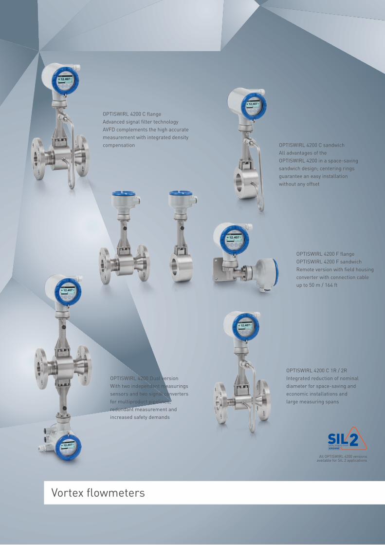
Vortex flowmeters
OPTISWIRL 4200 C flange Advanced signal filter technology AVFD complements the high accurate measurement with integrated density compensation OPTISWIRL 4200 C sandwich
All advantages of the OPTISWIRL 4200 in a space-saving sandwich design; centering rings guarantee an easy installation without any offset
OPTISWIRL 4200 Dual version With two independent measurings sensors and two signal converters for multiproduct pipelines, redundant measurement and increased safety demands
All OPTISWIRL 4200 versions available for SIL 2 applications
OPTISWIRL 4200 F flange OPTISWIRL 4200 F sandwich Remote version with field housing converter with connection cable up to 50 m / 164 ft
OPTISWIRL 4200 C 1R / 2R Integrated reduction of nominal diameter for space-saving and economic installations and large measuring spans
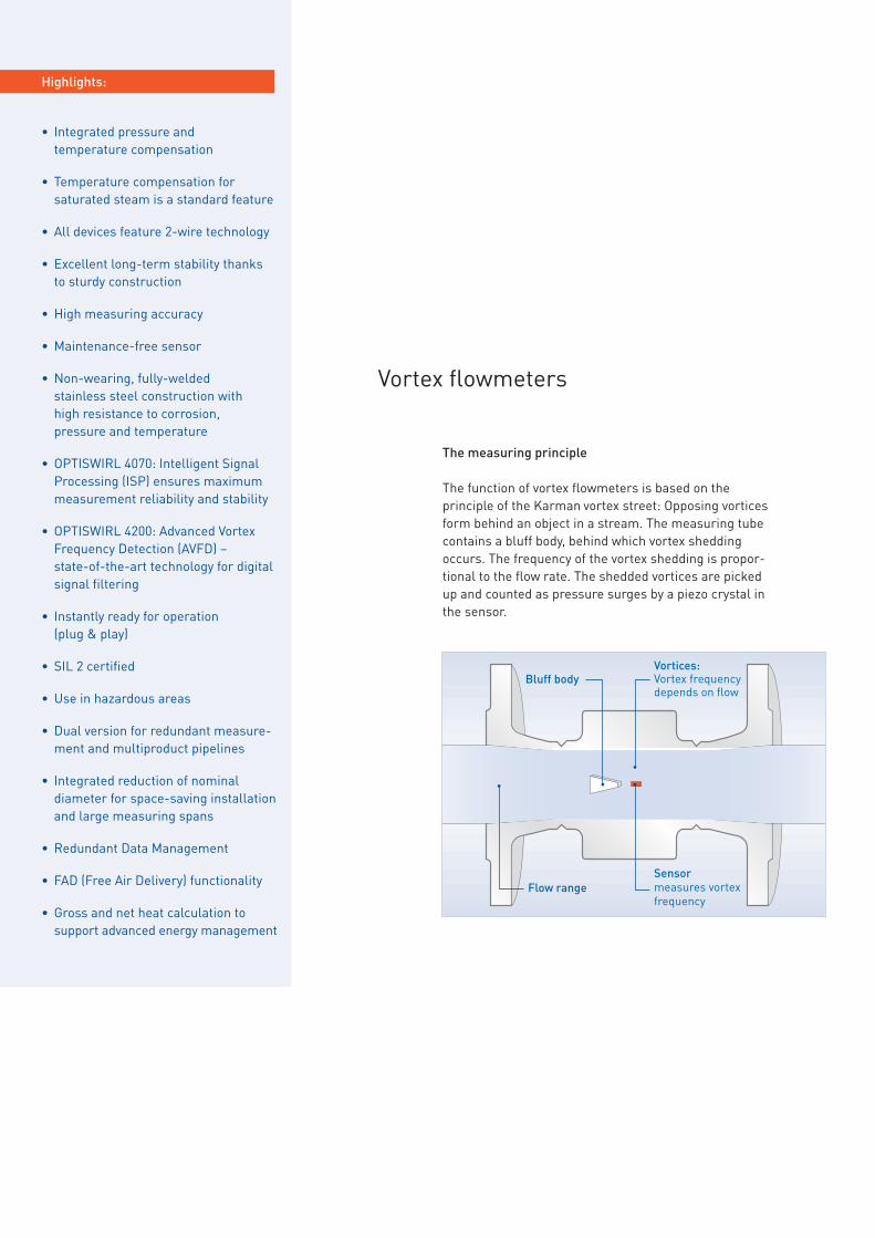
The measuring principle
The function of vortex flowmeters is based on the principle of the Karman vortex street: Opposing vortices form behind an object in a stream. The measuring tube contains a bluff body, behind which vortex shedding occurs. The frequency of the vortex shedding is propor-tional to the flow rate. The shedded vortices are picked up and counted as pressure surges by a piezo crystal in the sensor.
Vortex flowmeters
Highlights:
• Integrated pressure and temperature compensation
• Temperature compensation for saturated steam is a standard feature
• All devices feature 2-wire technology
• Excellent long-term stability thanks to sturdy construction
• High measuring accuracy
• Maintenance-free sensor
• Non-wearing, fully-welded stainless steel construction with high resistance to corrosion, pressure and temperature
• OPTISWIRL 4070: Intelligent Signal Processing (ISP) ensures maximum measurement reliability and stability
• OPTISWIRL 4200: Advanced Vortex Frequency Detection (AVFD) – state-of-the-art technology for digital signal filtering
• Instantly ready for operation (plug & play)
• SIL 2 certified
• Use in hazardous areas
• Dual version for redundant measure-ment and multiproduct pipelines
• Integrated reduction of nominal diameter for space-saving installation and large measuring spans
• Redundant Data Management
• FAD (Free Air Delivery) functionality
• Gross and net heat calculation to support advanced energy management
Vortices: Vortex frequency depends on flow
Bluff body
Sensor measures vortex frequency
Flow range

45
Allrounder with integrated pressure and temperature compensation
Industries:
• Chemical
• Metal
• Power plants
• Oil and gas
• Petrochemical
• Pulp and paper
• Food and beverage
• Water and wastewater
Vortex flowmeters are suitable for a wide range of media. This is particularly true of the KROHNE OPTISWIRL: It measures both conducting and non-conducting liquids as well as all industrial gases. It also measures saturated steam and superheated steam, com-pressed air and nitrogen, liquefied gas and flue gas, demineralized water and boiler feed water, solvents and heat transfer oil.
The KROHNE OPTISWIRL even masters fluctuating pressures and temperatures thanks to integrated pressure and temperature compensation.
The collection of the volume flow and the process data at only one point ensures accurate density compansation and combines high system accuracy with low investment costs. Internal gross and net heat calculation complete the device to be a reliable partner for advanced energy management.
Highest reliability and lowest probability of failure: The new OPTISWIRL 4200 was designed for safety related applications right from the start. Both its hardware and its software are developed to meet the strict requirements of SIL 2 safety functions: On demand as well as continuously!
Vortex flowmeters

46
The universal device with standard integrated temperature compensa-tion for saturated steam and optionally pressure compensation for superheated steam, gases, wet gases
Advanced signal filter technology AVFD complements the high accu-rate measurement with integrated density compensation
The first vortex flowmeter with integrated pressure and temperature compensation
All advantages of the OPTISWIRL 4200 in a space-saving sandwich design; centering rings guarantee an easy installation without any offset
With two independent measuring sensors and two signal converters for multiproduct pipelines, redundant measurement and increased safety demands
With two independent measurings sensors and two signal converters multiproduct pipelines, redundant measurement and increased safety demands
OPTISWIRL 4070 C/F flange OPTISWIRL 4200 C/F flange OPTISWIRL 4070 C/F sandwich OPTISWIRL 4200 C/F sandwich OPTISWIRL 4070 Dual version OPTISWIRL 4200 Dual version
Signal converter VFC 070 C/F VFC 200 C/F VFC 070 C/F Signal converter VFC 200 C/F VFC 070 VFC 200Measuring accuracy Re > 20000 ±0.75% for liquids
Re > 20000 ±1% for gases and steam10000 < Re < 20000 ±2% for liquids, gases and steam
Re > 20000 ±0.75% for liquidsRe > 20000 ±1% for gases and steam10000 < Re < 20000 ±2% for liquids, gases and steam
Re > 20000 ±0.75% for liquidsRe > 20000 ±1% for gases and steam10000 < Re < 20000 ±2% for liquids, gases and steam
Measuring accuracy Re > 20000 ±0.75% for liquidsRe > 20000 ±1% for gases and steam10000 < Re < 20000 ±2% for liquids, gases and steam
Re > 20000 ±0.75% for liquidsRe > 20000 ±1% for gases and steam10000 < Re < 20000 ±2% for liquids, gases and steam
Re > 20000 ±0.75% for liquidsRe > 20000 ±1% for gases and steam10000 < Re < 20000 ±2% for liquids, gases and steam
Repeatability ±0.1% ±0.1% ±0.1% Repeatability ±0.1% ±0.1% ±0.1% Product temperature -40…+240°C; -40…+464°F -40…+240°C; -40…+464°F -40…+240°C; -40…+464°F Product temperature -40…+240°C; -40…+464°F -40…+240°C; -40…+464°F -40…+240°C; -40…+464°FOutputs mA, pulse mA, pulse/frequency/status/limit
switchmA, pulse Outputs mA, pulse/frequency/status/limit
switchmA, pulse mA, pulse/frequency/status/limit
switchInput - mA - Input mA - mACommunication HART® HART®, PA, FF HART® Communication HART®, PA, FF HART® HART®, PA, FFPower supply (Non Ex) 14…30 VDC 12…30 VDC 14…30 VDC Power supply (Non Ex) 12…30 VDC 14…30 VDC 12…30 VDCPower supply (Ex) 14…36 VDC 12…36 VDC 14…36 VDC Power supply (Ex) 12…36 VDC 14…36 VDC 12…36 VDCProtection category IP66/67 IP66/67, optional IP66/68 IP66/67 Protection category IP66/67, optional IP66/68 IP66/67 IP66/67, optional IP66/68Housing material Aluminum Aluminum, stainless steel Aluminum Housing material Aluminum, stainless steel Aluminum Aluminum, stainless steelFunctionality FunctionalityFAD FAD FAD FAD FAD FAD FAD FADGross and net heat calculation
Gross heat Gross and net heat Gross heat Gross and net heat calculation
Gross and net heat Gross heat Gross and net heat
Measuring sensor VFM 4000 flange VFM 4000 flange VFM 4000 sandwich Measuring sensor VFM 4000 sandwichProcess connections Process connectionsEN 1092-1 DN15…300; PN16, 25, 40, 63, 100 DN15…300; PN16, 25, 40, 63, 100 DN15…100; PN16, 25, 40, 63, 100 EN 1092-1 DN15…100; PN16, 25, 40, 63, 100 DN25…100; PN16, 25, 40, 63, 100 DN25…100; PN16, 25, 40, 63, 100ASME B16.5 1/2…12"; CL 150, 300, 600 1/2…12"; CL 150, 300, 600, 900, 1500 1/2…4"; CL 150, 300, 600 ASME B16.5 1/2…4"; CL 150, 300, 600 1…4"; CL 150, 300, 600 1…4"; CL 150, 300, 600, 900, 1500Temperature ranges Temperature rangesProcess -40…+240°C; -40…+464°F -40…+240°C; -40…+464°F -40…+240°C; -40…+464°F Process -40…+240°C; -40…+464°F -40…+240°C; -40…+464°F -40…+240°C; -40…+464°FAmbient (Non Ex) -40…+85°C; -40…+185°F -40…+85°C; -40…+185°F -40…+85°C; -40…+185°F Ambient (Non Ex) -40…+85°C; -40…+185°F -40…+85°C; -40…+185°F -40…+85°C; -40…+185°FAmbient (Ex) -40…+65°C; -40…+149°F -40…+65°C; -40…+149°F -40…+65°C; -40…+149°F Ambient (Ex) -40…+65°C; -40…+149°F -40…+65°C; -40…+149°F -40…+65°C; -40…+149°FMaterials MaterialsMeasuring sensor 1.4404/316L, Hastelloy® C22 1.4404/316L, Hastelloy® C22 1.4404/316L, Hastelloy® C22 Measuring sensor 1.4404/316L, Hastelloy® C22 1.4404/316L, Hastelloy® C22 1.4404/316L, Hastelloy® C22Sensor seal 1.4435/316L, Hastelloy® C276 1.4435/316L, Hastelloy® C276 1.4435/316L, Hastelloy® C276 Sensor seal 1.4435/316L, Hastelloy® C276 1.4435/316L, Hastelloy® C276 1.4435/316L, Hastelloy® C276Protection category Protection categoryMeasuring sensor IP66/67 IP66/67 IP66/67 Measuring sensor IP66/67 IP66/67 IP66/67Reduction of nominal diameter
Reduction of nominal diameter
Measuring sensor 1 or 2 steps reduced bore meter 1 or 2 steps reduced bore meter - Measuring sensor - 1 or 2 steps reduces bore meter 1 or 2 steps reduced bore meterApprovals ApprovalsEx ATEX, FM (USA), IECEx, NEPSI ATEX, FM (USA and Canada), IECEx ATEX, FM (USA), IECEx, NEPSI Ex ATEX, FM (USA and Canada), IECEx ATEX, FM (USA), IECEx, NEPSI ATEX, FM (USA and Canada), IECExFunctional Safety - SIL 2 - Functional Safety SIL 2 - SIL 2
Vortex flowmeters

47Vortex flowmeters
The universal device with standard integrated temperature compensa-tion for saturated steam and optionally pressure compensation for superheated steam, gases, wet gases
Advanced signal filter technology AVFD complements the high accu-rate measurement with integrated density compensation
The first vortex flowmeter with integrated pressure and temperature compensation
All advantages of the OPTISWIRL 4200 in a space-saving sandwich design; centering rings guarantee an easy installation without any offset
With two independent measuring sensors and two signal converters for multiproduct pipelines, redundant measurement and increased safety demands
With two independent measurings sensors and two signal converters multiproduct pipelines, redundant measurement and increased safety demands
OPTISWIRL 4070 C/F flange OPTISWIRL 4200 C/F flange OPTISWIRL 4070 C/F sandwich OPTISWIRL 4200 C/F sandwich OPTISWIRL 4070 Dual version OPTISWIRL 4200 Dual version
Signal converter VFC 070 C/F VFC 200 C/F VFC 070 C/F Signal converter VFC 200 C/F VFC 070 VFC 200Measuring accuracy Re > 20000 ±0.75% for liquids
Re > 20000 ±1% for gases and steam10000 < Re < 20000 ±2% for liquids, gases and steam
Re > 20000 ±0.75% for liquidsRe > 20000 ±1% for gases and steam10000 < Re < 20000 ±2% for liquids, gases and steam
Re > 20000 ±0.75% for liquidsRe > 20000 ±1% for gases and steam10000 < Re < 20000 ±2% for liquids, gases and steam
Measuring accuracy Re > 20000 ±0.75% for liquidsRe > 20000 ±1% for gases and steam10000 < Re < 20000 ±2% for liquids, gases and steam
Re > 20000 ±0.75% for liquidsRe > 20000 ±1% for gases and steam10000 < Re < 20000 ±2% for liquids, gases and steam
Re > 20000 ±0.75% for liquidsRe > 20000 ±1% for gases and steam10000 < Re < 20000 ±2% for liquids, gases and steam
Repeatability ±0.1% ±0.1% ±0.1% Repeatability ±0.1% ±0.1% ±0.1% Product temperature -40…+240°C; -40…+464°F -40…+240°C; -40…+464°F -40…+240°C; -40…+464°F Product temperature -40…+240°C; -40…+464°F -40…+240°C; -40…+464°F -40…+240°C; -40…+464°FOutputs mA, pulse mA, pulse/frequency/status/limit
switchmA, pulse Outputs mA, pulse/frequency/status/limit
switchmA, pulse mA, pulse/frequency/status/limit
switchInput - mA - Input mA - mACommunication HART® HART®, PA, FF HART® Communication HART®, PA, FF HART® HART®, PA, FFPower supply (Non Ex) 14…30 VDC 12…30 VDC 14…30 VDC Power supply (Non Ex) 12…30 VDC 14…30 VDC 12…30 VDCPower supply (Ex) 14…36 VDC 12…36 VDC 14…36 VDC Power supply (Ex) 12…36 VDC 14…36 VDC 12…36 VDCProtection category IP66/67 IP66/67, optional IP66/68 IP66/67 Protection category IP66/67, optional IP66/68 IP66/67 IP66/67, optional IP66/68Housing material Aluminum Aluminum, stainless steel Aluminum Housing material Aluminum, stainless steel Aluminum Aluminum, stainless steelFunctionality FunctionalityFAD FAD FAD FAD FAD FAD FAD FADGross and net heat calculation
Gross heat Gross and net heat Gross heat Gross and net heat calculation
Gross and net heat Gross heat Gross and net heat
Measuring sensor VFM 4000 flange VFM 4000 flange VFM 4000 sandwich Measuring sensor VFM 4000 sandwichProcess connections Process connectionsEN 1092-1 DN15…300; PN16, 25, 40, 63, 100 DN15…300; PN16, 25, 40, 63, 100 DN15…100; PN16, 25, 40, 63, 100 EN 1092-1 DN15…100; PN16, 25, 40, 63, 100 DN25…100; PN16, 25, 40, 63, 100 DN25…100; PN16, 25, 40, 63, 100ASME B16.5 1/2…12"; CL 150, 300, 600 1/2…12"; CL 150, 300, 600, 900, 1500 1/2…4"; CL 150, 300, 600 ASME B16.5 1/2…4"; CL 150, 300, 600 1…4"; CL 150, 300, 600 1…4"; CL 150, 300, 600, 900, 1500Temperature ranges Temperature rangesProcess -40…+240°C; -40…+464°F -40…+240°C; -40…+464°F -40…+240°C; -40…+464°F Process -40…+240°C; -40…+464°F -40…+240°C; -40…+464°F -40…+240°C; -40…+464°FAmbient (Non Ex) -40…+85°C; -40…+185°F -40…+85°C; -40…+185°F -40…+85°C; -40…+185°F Ambient (Non Ex) -40…+85°C; -40…+185°F -40…+85°C; -40…+185°F -40…+85°C; -40…+185°FAmbient (Ex) -40…+65°C; -40…+149°F -40…+65°C; -40…+149°F -40…+65°C; -40…+149°F Ambient (Ex) -40…+65°C; -40…+149°F -40…+65°C; -40…+149°F -40…+65°C; -40…+149°FMaterials MaterialsMeasuring sensor 1.4404/316L, Hastelloy® C22 1.4404/316L, Hastelloy® C22 1.4404/316L, Hastelloy® C22 Measuring sensor 1.4404/316L, Hastelloy® C22 1.4404/316L, Hastelloy® C22 1.4404/316L, Hastelloy® C22Sensor seal 1.4435/316L, Hastelloy® C276 1.4435/316L, Hastelloy® C276 1.4435/316L, Hastelloy® C276 Sensor seal 1.4435/316L, Hastelloy® C276 1.4435/316L, Hastelloy® C276 1.4435/316L, Hastelloy® C276Protection category Protection categoryMeasuring sensor IP66/67 IP66/67 IP66/67 Measuring sensor IP66/67 IP66/67 IP66/67Reduction of nominal diameter
Reduction of nominal diameter
Measuring sensor 1 or 2 steps reduced bore meter 1 or 2 steps reduced bore meter - Measuring sensor - 1 or 2 steps reduces bore meter 1 or 2 steps reduced bore meterApprovals ApprovalsEx ATEX, FM (USA), IECEx, NEPSI ATEX, FM (USA and Canada), IECEx ATEX, FM (USA), IECEx, NEPSI Ex ATEX, FM (USA and Canada), IECEx ATEX, FM (USA), IECEx, NEPSI ATEX, FM (USA and Canada), IECExFunctional Safety - SIL 2 - Functional Safety SIL 2 - SIL 2

The modular product line
OPTIBAR OP 1000 Standard orifice plates with single bore tapping for cost-effective flow measurement
OPTIBAR OP 1200 Robust split ring orifice plates with interchangeable orifice plate
OPTIBAR PT 2000Averaging pitot tubes for energy-efficient flow measurement with lowest pressure loss
OPTIBAR DP 7060 Differential pressure transmitter for all flow applications, already with integrated absolute pressure measurement
Primary elements
Pressure transmitters

Differential pressure flow measurement
Calibrated meter runs
Flow computers
OPTIBAR MR 1000 Calibrated meter run with orifice plate for nominal sizes DN 15…50 / 3/4…2"
OPTIBAR MR 2000 Calibrated meter run with averaging pitot tube for nominal sizes DN 15…50 / 3/4…2"
OPTIBAR FC 1000 Flow computer for pressure and temperature compensated gas and steam measurement and gross/net energy calculation
Accessories
Accessories for safe and easy installation of pressure transmitters in the process:
• Manometer and barstock valves, 3-/5-way valve manifolds, also for steam and high temperature applications
• Condensate pots for steam applications • Fittings, seals, blind-plugs, oval flange
adapter and gauge snubber

qv
A
50 Differential pressure flow measurement
Differential pressure flow measurement
The measuring principle
For over 100 years, the process industry has used the Differential Pressure (DP) flow measurement method to determine the volume or mass of liquids, gases and steam in commercial use.
With DP, pressure is measured at two points across a restriction in the line – for example, a primary element. Using the Bernoulli equation, the difference in pressure between these two points indicates flow velocity and, because the pipe size is known, a volume flow rate can be calculated.
Today, DP is being constantly improved and adapted to meet the requirements of modern processes, and KROHNE is helping to lead the way.
Pitot tube
The pitot tube offers you a simple, cost-efficient flow measurement solution which can be trusted to deliver accurate results over the long term. It is an excellent alternative to orifice plates for:
• Applications that require a low pressure loss • Retrofitting of existing pipelines with flow measurement
• Line sizes >DN 300/12" • Low pressure gases
A pitot tube consisting of two chambers is placed in the pipe transversely to the direction of the flow. An upstream chamber faces the flow and a downstream chamber is placed at the back of the probe.
The impact of the medium against the upstream chamber causes an overpressure that adds to the static pressure in the pipe. Depending on its shape, a negative pressure builds up in the downstream chamber. Both pressures are transmitted to a differential pressure transmitter that converts the difference between the two chambers into an output signal.
Flow velocity is calculated using the differential pressure and medium density v = k x √2 x ∆p/ρ. Volume flow is calculated from the flow velocity and the crosssection area qv = v x A.

Dd
qv
51Differential pressure flow measurement
Orifice plates
Orifice plates work by restricting the flow of the liquid, gas or steam being monitored. According to the Bernoulli equation, the flow velocity increases at the restriction, and the static pressure drops. The difference in pressure at the measuring point is a measure for the flow velocity of the medium.
Volume flow is calculated from the flow velocity and the cross-section area: qv = v x A
The diameter ratio β = d/D is determined for each measuring point, allowing each one to be optimised for specific requirements, including short inlet/outlet, low pressure loss and instances of small overall uncertainty.
Orifice plate primary elements are worldwide standardised according to ISO 5167.

Highlights:
• Worldwide standardised flow measurement principle according to ISO 5167
• All measurement uncertainties under operational conditions are known and can be calculated
• Volume or mass flow measurement of liquids, gases or steam
• Medium temperatures -200…+1000°C / -328…1832°F
• Process pressure up to 420 bar / 6091 psi
• Line sizes from DN25…12000 / 1…470"
• One pressure transmitter for all flow applications, compact or remote version
• Integrated absolute pressure measurement
• Pressure and temperature compen- sation available as option
• Wet-calibrated meter runs for small line sizes and low measurement uncertainty
• Optimisation of measuring points according to a given specification, e.g. short inlet/outlet, low pressure loss, small overall uncertainty, etc.
• Change of pressure transmitter without process interruption
• No moving parts
• NACE compliant materials
• Compliant to PED 97/23/EC with CE marking
• Use in hazardous areas
• Large choice of materials for corrosive and non-corrosive mediums
• Wet calibration up to DN 3000 / 120" possible
• 4…20 mA HART® 7 / HART® SIL 2/3, FOUNDATION™ fieldbus, PROFIBUS® PA as communication options
• Smallest measuring span 10 mbar / 0.145 psi gauge
Introducing OPTIBAR differential pressure
flow measurement products
Today, in over 40 % of all flow applications, differential pressure meters are still the first choice. With the release of the OPTIBAR series, KROHNE is extending its process instrumentation portfolio to meet this demand.
The range includes a variety of modulartransmitters, application specific diaphragmseals, primary elements, accessories, valvesand manifolds. This offers you the option to buy, from one source, single DP pressure transmitters as well as complete DP flow measuring points, with matched, preconfig-ured components, (wet) calibrated and ready to install.
Modular design concept

53
Industries:
• Oil and gas
• Chemical
• Petrochemical
• Heating, Ventilation and Air Conditioning (HVAC)
• Energy
• Metal and mining
• Food and beverages
Complete measuring points
KROHNE will provide you with all necessary instruments for your flow measurement point: from primary elements, up to a flow computer for gas, liquid and steam calculations. For measurement uncertainties due to changing process conditions, the flow computer holds appropriate algorithms for all primary elements. By adding temperature and pressure sensors, density compensation or gross and net energy calcula-tions are also possible. When commissioning a complete measuring point from us, investment costs like primary element design, component assembly up to pre-parametrisation of the differential pressure transmitter and flow computer are all less. And there are no additional costs for piping, installation and testing at the measur-ing point. KROHNE’s approach to design also guarantees that up to 70 % of potential leakage points will be eliminated, cutting service and maintenance costs.
Complete DP flow measuring point for compensated volume/mass flow
Annular chamber orifice plate
Flow computer
3-way manifold
Differential pressure transmitter
Absolute pressure transmitter
Shut-off valve
Temperature sensor
Compensated mass flow
PLC/DCS

54 Differential pressure flow measurement
Averaging pitot tubes for energy- efficient flow measurement with lowest pressure loss
Standard orifice plates with single bore tapping for cost- effective flow measurement
Robust split ring orifice plates with interchangeable orifice plate
Calibrated meter run with orifice plate for nominal sizes DN 15…50 / 3/4…2"
Calibrated meter run with averaging pitot tube for nominal sizes DN 15…50 / 3/4…2"
OPTIBAR PT 2000 OPTIBAR OP 1000 OPTIBAR OP 1200 OPTIBAR MR 1000 OPTIBAR MR 2000
Medium Gas, liquid, steam Gas, liquid, steam Gas, liquid, steam Gas, liquid, steam Gas, liquid, steamType Compact, remote Compact, remote Compact, remote Compact CompactSizing KROHNE standard ISO 5167:2003; ASME MFC-3M 2004;
AGA 3; ASME PTC 19.5 2004ISO 5167:2003; ASME MFC-3M 2004; AGA 3; ASME PTC 19.5 2004
ISO 5167:2003; ASME MFC-3M 2004; AGA 3; ASME PTC 19.5 2004
KROHNE standard
Accuracy < ±1% uncalibrated; < ±0.5% calibrated
< ±0.6…0.8% < ±0.6…0.8% < ±0.5…1.5% calibrated < ±0.5…1% calibrated
Turn down ration (calibrated) 1:5 (1:7) 1:3 (1:6) 1:3 (1:6) 1:6 1:6Pressure loss 5…12% 40…95% 40…95% 40…95% 5…12%Max. pressure PN40 PN40; PN63; PN100 PN40; PN63; PN100 420 bar; 6091.6 psi 420 bar; 6091.6 psiMax. temperature +450°C; +842°F +450°C; +842°F +450°C; +842°F +450°C; +842°F +450°C; +842°FLine size DN50…2000; 2…800" DN50…2000; 2…800" DN50…2000; 2…800“ DN15…50; 3/4…2" DN15…50; 3/4…2"Material primary element 316L 316L 316L A105, 316L A105, 316LMaterial mounting parts A105, 316L, 16Mo3 A105, 316L, 16Mo3 A105, 316L, 16Mo3 316L 316LOptional temperature probe Yes No No No Yes
Differential pressure transmitter for flow applications, already with integrated absolute pressure measurement
Differential pressure transmitter for flow applications, already with integrated absolute pressure measurement
OPTIBAR DP 7060 C OPTIBAR DP 7060
Accuracy (of calibrated span)Reference accuracy DP < ±0.065% up to TD 10:1 < ±0.065% up to TD 10:1Long-term stability ±0.1% within 5 years < ±0,1%within 5 yearsTotal performance < ±0.18% < ±0.18%
Max. turn down 100:1 100:1
Reference accuracy pabs. < ±0.1% < ±0.1%Pressure rangeSensor Piezoresistive PiezoresistiveMeasurement range 10, 30, 100, 500 mbar, 3, 16 bar; 0.15,
0.4, 1.4, 7.2, 43.5, 232 psi10, 30, 100, 500 mbar, 3, 16 bar; 0.15, 0.4, 1.4, 7.2, 43.5, 232 psi
Line pressure 40, 160, 420 bar; 580.1, 2320.6, 6091.6 psi
40, 160, 420 bar; 580.1, 2320.6, 6091.6 psi
Temperature rangeProcess -40…+85°C; -40…+185°F -40…+85°C; -40…+185°FAmbient -40…+80°C; -40…+185°F -40…+80°C; -40…+185°FConfigurationPC Tool Free DTM, also USB interface Free DTM, also USB interfaceSoftware / HHT Yes - generic and DD Yes - generic and DDLocal With optional display and
adjustment moduleWith optional display and adjustment module
MaterialHousing DIN housing in 1- or 2-chamber
configuration: 316L, aluminium, 316L (electro-polished), plastic (PBT)
DIN housing in 1- or 2-chamber configuration: 316L, aluminium, 316L (electro-polished), plastic (PBT)
Diaphragm material 316L , Hastelloy C276, Monel 400, Tantal, Monel 400 with gold plating
316L, Hastelloy C276, Monel 400, Tantal, Monel 400 with gold plating
CommunicationOutput 4…20 mA, HART® 7, PA, FF 4…20 mA, HART® 7, PA, FFApprovals
Ex ATEX / IECEx Ex ia, Ex d, Ex d ia ATEX / IECEx Ex ia, Ex d, Ex d ia

55Differential pressure flow measurement
Averaging pitot tubes for energy- efficient flow measurement with lowest pressure loss
Standard orifice plates with single bore tapping for cost- effective flow measurement
Robust split ring orifice plates with interchangeable orifice plate
Calibrated meter run with orifice plate for nominal sizes DN 15…50 / 3/4…2"
Calibrated meter run with averaging pitot tube for nominal sizes DN 15…50 / 3/4…2"
OPTIBAR PT 2000 OPTIBAR OP 1000 OPTIBAR OP 1200 OPTIBAR MR 1000 OPTIBAR MR 2000
Medium Gas, liquid, steam Gas, liquid, steam Gas, liquid, steam Gas, liquid, steam Gas, liquid, steamType Compact, remote Compact, remote Compact, remote Compact CompactSizing KROHNE standard ISO 5167:2003; ASME MFC-3M 2004;
AGA 3; ASME PTC 19.5 2004ISO 5167:2003; ASME MFC-3M 2004; AGA 3; ASME PTC 19.5 2004
ISO 5167:2003; ASME MFC-3M 2004; AGA 3; ASME PTC 19.5 2004
KROHNE standard
Accuracy < ±1% uncalibrated; < ±0.5% calibrated
< ±0.6…0.8% < ±0.6…0.8% < ±0.5…1.5% calibrated < ±0.5…1% calibrated
Turn down ration (calibrated) 1:5 (1:7) 1:3 (1:6) 1:3 (1:6) 1:6 1:6Pressure loss 5…12% 40…95% 40…95% 40…95% 5…12%Max. pressure PN40 PN40; PN63; PN100 PN40; PN63; PN100 420 bar; 6091.6 psi 420 bar; 6091.6 psiMax. temperature +450°C; +842°F +450°C; +842°F +450°C; +842°F +450°C; +842°F +450°C; +842°FLine size DN50…2000; 2…800" DN50…2000; 2…800" DN50…2000; 2…800“ DN15…50; 3/4…2" DN15…50; 3/4…2"Material primary element 316L 316L 316L A105, 316L A105, 316LMaterial mounting parts A105, 316L, 16Mo3 A105, 316L, 16Mo3 A105, 316L, 16Mo3 316L 316LOptional temperature probe Yes No No No Yes
Differential pressure transmitter for flow applications, already with integrated absolute pressure measurement
Differential pressure transmitter for flow applications, already with integrated absolute pressure measurement
OPTIBAR DP 7060 C OPTIBAR DP 7060
Accuracy (of calibrated span)Reference accuracy DP < ±0.065% up to TD 10:1 < ±0.065% up to TD 10:1Long-term stability ±0.1% within 5 years < ±0,1%within 5 yearsTotal performance < ±0.18% < ±0.18%
Max. turn down 100:1 100:1
Reference accuracy pabs. < ±0.1% < ±0.1%Pressure rangeSensor Piezoresistive PiezoresistiveMeasurement range 10, 30, 100, 500 mbar, 3, 16 bar; 0.15,
0.4, 1.4, 7.2, 43.5, 232 psi10, 30, 100, 500 mbar, 3, 16 bar; 0.15, 0.4, 1.4, 7.2, 43.5, 232 psi
Line pressure 40, 160, 420 bar; 580.1, 2320.6, 6091.6 psi
40, 160, 420 bar; 580.1, 2320.6, 6091.6 psi
Temperature rangeProcess -40…+85°C; -40…+185°F -40…+85°C; -40…+185°FAmbient -40…+80°C; -40…+185°F -40…+80°C; -40…+185°FConfigurationPC Tool Free DTM, also USB interface Free DTM, also USB interfaceSoftware / HHT Yes - generic and DD Yes - generic and DDLocal With optional display and
adjustment moduleWith optional display and adjustment module
MaterialHousing DIN housing in 1- or 2-chamber
configuration: 316L, aluminium, 316L (electro-polished), plastic (PBT)
DIN housing in 1- or 2-chamber configuration: 316L, aluminium, 316L (electro-polished), plastic (PBT)
Diaphragm material 316L , Hastelloy C276, Monel 400, Tantal, Monel 400 with gold plating
316L, Hastelloy C276, Monel 400, Tantal, Monel 400 with gold plating
CommunicationOutput 4…20 mA, HART® 7, PA, FF 4…20 mA, HART® 7, PA, FFApprovals
Ex ATEX / IECEx Ex ia, Ex d, Ex d ia ATEX / IECEx Ex ia, Ex d, Ex d ia
Flow computer for pressure and temperature compensated gas and steam measurement and gross/net energy calculation
OPTIBAR FC 1000
MediumWater, steam IAPWS-97Natural gas AGA-8 G1/G2 (ISO20765-1)
GERG-88 (ISO 12213-3)AGA-NX19
Gases Ideal gas equation, optional acc. Redlich-Kwong, Redlich-Kwong-Soave, Peng-Robinson
Thermal oilTherminol66, Shell Thermia B and various other oils by polynominal approximation
Other mediums Assumption of constant physical properties
Process inputsPrimary elements ISO 5167, AGA-3Volume flow or velocity Mass flow calculationTemperature sensor 2x Pt100
PipeThermal expansion Acc. AGA-3, VDI-2040, ISO 5167InterfacesModbus Modbus RTU and ASCiiEthernet Web server, software updates,
backup/restore of parametersFSK modem Compatible to HART® field devices;
digital transfer of measuring values and device parameters
Analog signals 1x Relay (6A; 230 VAC)2x SPDT (50 mA; 60 VDC)
Display adapter Link to a remote display module (optional)
User interface
Display 4.3‘‘ TFT color displayControls Capacitive touchscreenMemory SD-card slotInputsFlow 0/4…20 mA active/passive, HART®,
frequency or pulse inputsPressure 0/4…20 mA active/passiveTemperature 3- or 4-wire Pt100, max. length
250 m; 820.2 ft; all inputs are galvantically isolated
OutputsAnalog outputs 2x 4…20 mASwitching outputs 1x Relay (6A; 230 VAC)
2x SPDT (50mA; 60 VDC) Dimensions Panel housing 135x65x120 mm;
5.28x2.4x4.8 inch: IP20External display 144x83x18 mm; 6x3.6x0.72 inch: IP65
Power supply 100…240 VAC or 18…36 VDC

DW 181Inline flow controller, process connection 3/4…2" NPT, G3/4…2
DW 182Inline flow controller, process connection DN15…65, 1/2…2 1/2" ASME
DW 183Inline flow controller, process connection DN65…200, 3…8" ASME
DW 184Insertion-type flow controller for pipe diameter ≥250 mm / 10", process connection DN150, 6" ASME
Measuring principle: Deflector plate
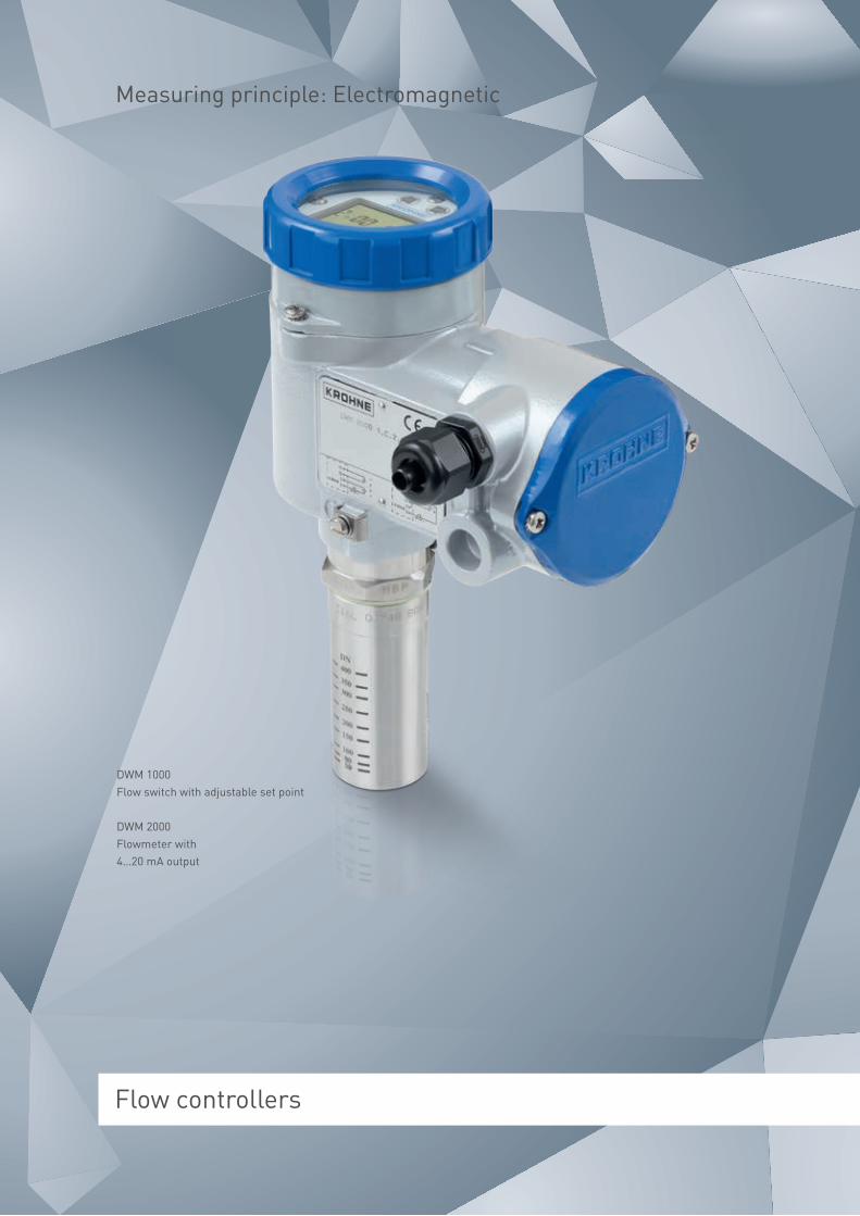
Flow controllers
DWM 1000Flow switch with adjustable set point
DWM 2000Flowmeter with 4…20 mA output
Measuring principle: Electromagnetic

Highlights DWM 1000, 2000:
• Measurement and monitoring of electrically conductive liquids, pastes and suspen-sions
• Sturdy construction, no moving parts, maintenance-free
• Wetted parts made of stainless steel and ceramic
• Converter is rotatable and removable under process conditions
• FT Tuchenhagen® connection for hygienic applications
• Optional LCD indicator e.g. for on-site calibration
• IP68 stainless steel housing for immersed applications
• Long sensor for large pipes or open channels
• For pipelines ≥DN25; 1"
The measuring principle
As early as 1832, Faraday tried to determine the speed of the current in the Thames by measuring the voltage induced in flowing water by the earth’s magnetic field. Electromagnetic flow measurement is based on Faraday’s Law of induction. According to this law, a specific voltage is induced in a conductor or conductive medium that moves through a magnetic field. This voltage is proportional to the speed of movement of the medium.
On electromagnetic flow controllers, the induced voltage is tapped via two measuring electrodes in conducting contact with the medium.
An electronic converts the signal into a proportional output signal.
Electromagnetic flow controllers
KROHNE invented and founded the industrially used electro- magnetic flow measuring technology more than 45 years ago. Today, we continue to impress customers with our innovations in this field.
With the DWM 1000 and DWM 2000 flow controllers, we offer two sturdy units.
Depending on the design, the flow speed is monitored (DWM 1000) or measured and output via a 4…20 mA (DWM 2000).
The only prerequisite is that the electrical conductivity of the medium be at least 20 µS/cm. DWM 1000 and DWM 2000 flow controllers are ideal for use with largely homogenous liquids, pastes and sludges – even with solid content.
Sturdy and maintenance-free: Flow switch DWM 1000
and flowmeter DWM 2000
Industries:
• Water and wastewater
• Food and beverage
• Chemical
• Pharmaceutical
• Process industry
• Pulp and paper
• Mining and minerals
• Steel

59Flow controllers
Highlights DW 181 to DW 184:
• One or two dry reed limit switches
• For horizontal or vertical pipes (DW 181 to 183)
• Insertion-type for horizontal pipes Ø ≥250 mm; 10" (DW 184)
• Available with threaded, flange or mounting flange connectors
• Two different flow displays (G and A) to choose from (DW 181 to183)
• High-temperature design up to max. +300 °C; +572 °F
• Ex-versions (Ex d, Ex i)
• Tropical version with Amphenol® sockets and a double coating of epoxy on device
• Local indication without power supply, can be used as variable area flowmeter
• Additional amplifying relay for switching energies up to 1200 VA
Industries:
• Power plants
• Steel
• Mining
• Petrochemical
• Oil and gas
• Chemical
• Food and beverage
• Water and wastewater
The measuring principle
With the flow controllers DW 181 to 184, the liquid flows against a springmounted disc. The position of the disc changes with increasing flow. A built-in magnet transmits the position to the display and also activates the limit switch.
Mechanical flow controllers
With the flow controllers DW 181, 182, 183 and 184, KROHNE offers the ideal flow control solution for virtually any process connection.
Each device is equipped with a limit switch (dry reed contact) and it is possible to install another switch at any time. For greater switching energies of up to 1200 VA, an additional amplifying relay can be installed.
Choose the display which is most adapted to your needs: DW 181, 182, 183, 184 can be ordered with two display types, G and A.
The G display enables visual monitoring of the flow via a 10-point scale. The switching point can be changed at any point along the way. The A display allows a more accurate reading of the flow value (e.g. in l/h or in m3/h) via a scale. With this display, the switching points can be set even when there is no flow.
Always the right choice: Flow controllers
DW 181, 182, 183, and 184

60 Flow controllers
Flow controllers
Flow controllers based on disc actuated measuring principle
Flow controller based on electromagnetic measuring principle
Flow controller based on electromagnetic measuring principle
DW 181 to184 DWM 1000 DWM 2000
Measuring accuracy ±15% of switching point When v >1 m/s or 3.3 ft/s: accuracy ±5% of switching point when v <1 m/s or 3.3 ft/s: accuracy ±2% of switching point, ±3 cm/s; ±1.2 in/s
Measuring accuracy When v >1 m/s or 3.3 ft/s: accuracy ±5% of measured value (±2% if calibrated onsite) when v <1 m/s or 3.3 ft/s: accuracy ±2% of measured value, ±3 cm/s; ±1.2 in/s
Repeatability ±3% of switching point ±1% of switching point Repeatability ±1.5% of measured value
Limit switches 1 or 2 binary outputs; 1 or 2 relay outputs
1 binary output Limit switches -
Output - - Output 4…20 mA, 3-wire
Communication - - Communication RS232
Power supply Switching voltage AC: 24, 48, 110, 240 VAC; switching voltage DC: 24, 48, 110 VDC
48…240 VAC; 48 VDC; relay voltage: 48, 110, 240 VAC; 48 VDC
Power supply 12, 24 VDC, 50 mA
Protection category Polycarbonate housing: IP65 (non-Ex and Ex i)Aluminum housing: IP65 (non-Ex and Ex d)HT version (alu terminal box): IP20, 66
Aluminium housing: IP65 Stainless steel housing: IP68
Protection category Aluminium housing: IP65Stainless steel housing: IP68Aluminium housing with display: IP55
Nominal size Nominal size
Pipe diameter ≥DN15; 1/2" ≥DN25; 1" Pipe diameter ≥DN25; 1"
Connection 3/4…2" NPT; G3/4…2 DN15…200; 1/2…8"
Std fitting G1A; screw-on welding socket (Ø39 mm; Ø1.25") long sensor (option) 1 1/2" NPT; G1 1/2 screw-on welding socket (Ø60 mm; Ø2.4"); spool piece (option) DN25…50; 1…2", DN32; 1 1/4" on request; Optional FT Tuchenhagen VARIVENT® connection for hygienic applications
Connection Std fitting G1A, screw-on welding socket (Ø39 mm; Ø1.25") Optional long sensor 1 1/2" NPT; G1 1/2, screw-on welding socket (Ø60 mm; Ø2.4") spool piece (option) DN25…50; 1…2", DN32; 1 1/4" on request Optional FT Tuchenhagen VARIVENT® connection for hygienic applications
Pressure ratings Pressure ratings
Max. operating pressure 100 barg; 1450.4 psig, higher on request 25 barg; 362.6 psig Max. operating pressure 25 barg; 362.6 psig
Process conditions Process conditions
Medium Homogeneous, clean liquids Conductive liquids, pastes, slurries ≥20 mS/cm Medium Conductive liquids, pastes, slurries ≥20 mS/cm
Viscosity standard ≤30 mPas; 0.02 lb/fts - Viscosity standard -
Viscosity special version ≤250 mPas; 0.16 lb/fts - Viscosity special version -
Measuring range 0.2…4 m/s; 0.66…13.1 ft/s 0.1…9.9 m/s; 0.3…32.5 ft/s Measuring range 1…8 m/s; 3.3…26.3 ft/s
Temperature ranges Temperature ranges
Process -40…+150°C; -40…+302°F -25…+300°C; -13…+572°F (high temperature)
-25…+150°C; -13…+302°F -25…+60°C; -13…+140°F (IP68)
Process -25…+150°C; -13…+302°F -25…+60°C; -13…+140°F (IP68)
Ambient -40…+80°C; -40…+176°F -25…+60°C; -13…+140°F (high temperature)
-25…+60°C; -13…+140°F Ambient -25…+60°C; -13…+140°F
Materials Materials
Measuring tube Bronze, stainless steel Stainless steel, zirconium Measuring tube Stainless steel, zirconium
Measuring system Stainless steel Electrode: platinum Measuring system Electrode: platinum
Approvals Approvals
Ex ATEX - Ex -
Miscellaneous EAC EAC Miscellaneous EAC

61Flow controllers
Flow controllers based on disc actuated measuring principle
Flow controller based on electromagnetic measuring principle
Flow controller based on electromagnetic measuring principle
DW 181 to184 DWM 1000 DWM 2000
Measuring accuracy ±15% of switching point When v >1 m/s or 3.3 ft/s: accuracy ±5% of switching point when v <1 m/s or 3.3 ft/s: accuracy ±2% of switching point, ±3 cm/s; ±1.2 in/s
Measuring accuracy When v >1 m/s or 3.3 ft/s: accuracy ±5% of measured value (±2% if calibrated onsite) when v <1 m/s or 3.3 ft/s: accuracy ±2% of measured value, ±3 cm/s; ±1.2 in/s
Repeatability ±3% of switching point ±1% of switching point Repeatability ±1.5% of measured value
Limit switches 1 or 2 binary outputs; 1 or 2 relay outputs
1 binary output Limit switches -
Output - - Output 4…20 mA, 3-wire
Communication - - Communication RS232
Power supply Switching voltage AC: 24, 48, 110, 240 VAC; switching voltage DC: 24, 48, 110 VDC
48…240 VAC; 48 VDC; relay voltage: 48, 110, 240 VAC; 48 VDC
Power supply 12, 24 VDC, 50 mA
Protection category Polycarbonate housing: IP65 (non-Ex and Ex i)Aluminum housing: IP65 (non-Ex and Ex d)HT version (alu terminal box): IP20, 66
Aluminium housing: IP65 Stainless steel housing: IP68
Protection category Aluminium housing: IP65Stainless steel housing: IP68Aluminium housing with display: IP55
Nominal size Nominal size
Pipe diameter ≥DN15; 1/2" ≥DN25; 1" Pipe diameter ≥DN25; 1"
Connection 3/4…2" NPT; G3/4…2 DN15…200; 1/2…8"
Std fitting G1A; screw-on welding socket (Ø39 mm; Ø1.25") long sensor (option) 1 1/2" NPT; G1 1/2 screw-on welding socket (Ø60 mm; Ø2.4"); spool piece (option) DN25…50; 1…2", DN32; 1 1/4" on request; Optional FT Tuchenhagen VARIVENT® connection for hygienic applications
Connection Std fitting G1A, screw-on welding socket (Ø39 mm; Ø1.25") Optional long sensor 1 1/2" NPT; G1 1/2, screw-on welding socket (Ø60 mm; Ø2.4") spool piece (option) DN25…50; 1…2", DN32; 1 1/4" on request Optional FT Tuchenhagen VARIVENT® connection for hygienic applications
Pressure ratings Pressure ratings
Max. operating pressure 100 barg; 1450.4 psig, higher on request 25 barg; 362.6 psig Max. operating pressure 25 barg; 362.6 psig
Process conditions Process conditions
Medium Homogeneous, clean liquids Conductive liquids, pastes, slurries ≥20 mS/cm Medium Conductive liquids, pastes, slurries ≥20 mS/cm
Viscosity standard ≤30 mPas; 0.02 lb/fts - Viscosity standard -
Viscosity special version ≤250 mPas; 0.16 lb/fts - Viscosity special version -
Measuring range 0.2…4 m/s; 0.66…13.1 ft/s 0.1…9.9 m/s; 0.3…32.5 ft/s Measuring range 1…8 m/s; 3.3…26.3 ft/s
Temperature ranges Temperature ranges
Process -40…+150°C; -40…+302°F -25…+300°C; -13…+572°F (high temperature)
-25…+150°C; -13…+302°F -25…+60°C; -13…+140°F (IP68)
Process -25…+150°C; -13…+302°F -25…+60°C; -13…+140°F (IP68)
Ambient -40…+80°C; -40…+176°F -25…+60°C; -13…+140°F (high temperature)
-25…+60°C; -13…+140°F Ambient -25…+60°C; -13…+140°F
Materials Materials
Measuring tube Bronze, stainless steel Stainless steel, zirconium Measuring tube Stainless steel, zirconium
Measuring system Stainless steel Electrode: platinum Measuring system Electrode: platinum
Approvals Approvals
Ex ATEX - Ex -
Miscellaneous EAC EAC Miscellaneous EAC
KROHNE is committed to making communication convenient. Which is why our field devices communicate reliably with control-lers, control systems and PCs, and can also be used for a variety of control and regulating tasks. They meet all of the prerequisites for integration into modern plant asset management systems, based on integration technologies such as DD/EDD and FDT/DTM.
We are a longstanding member of PACTware™ and the FDT Group®. Since 2003, we have made DTMs available for our field devices with HART®, PROFIBUS® or FOUNDATION™ fieldbus interfaces.
For remote monitoring of applications such as water metering, KROHNE has developed a GSM-based solution for online data transmission and logging.
So you will always have the information you need conveniently close to hand.
Open for the future
PACTware™ and DTMs
PACTware™ is a manufacturer- independent tool based on FDT technology, providing device configuration and operation. It is free of charge.
DTMs are drivers for FDT-based systems. KROHNE DTMs are also available free of charge, without licence and without any functional restrictions.
Communication technology
Drivers · Protocols · Configuration · Diagnostics

63
Clear and fast access to process and device data from any level
KROHNE DTMs are available for many field devices with HART®, FOUNDATION™ fieldbus or PROFIBUS® communication inter- faces. They can be integrated into all FDT frame applications.
To assure conformity with the FDT standard, KROHNE DTMs are certified by the FDT Group after certification tests at the KROHNE FDT DTM Test Site, accredited in 2014. In addition, intensive interoperability tests with frames of major host system suppliers are performed.
KROHNE DTMs do not require any licence, providing full functio- nality free of charge. Next to standard operating features, they provide additional information for commissioning and application engineers.
For example, the DTM for the MFC 400 mass flow converter features clear and configurable diagnostics according to NAMUR recommendations NE 107, and an intuitive layout for fast access to the most used functions. DTMs for level devices are enhanced by fully configurable parameterisation screens for easy commissioning.
Together with PACTware™, KROHNE DTMs come alongside the device on a CD and can also be downloaded from KROHNE Download Centre at www.krohne.com
Diagnostic data is categorized or can be user-mapped into five categories according to the severity and ease reactions by the operator. Detailed configuration enables predictive maintenance.
Communication technology
Configuration of OPTITEMP TT 51 temperature transmitter via PACTware™
Cont
rol l
evel
Inte
rfac
e le
vel
Ethernet
FF
HSE
PLC/DCS
PROFIBUS DP
Linking device
4…20
mA/
HAR
T (E
x)
PRO
FIB
US
DP
GSM network
WWW SCADA PACTware
I/O system
Control and visualisation
PA
DP
Coupler
PRO
FIB
US
DP
FOU
ND
ATIO
N™
fiel
dbus
(Ex)
GSM
net
wor
k
PRO
FIB
US
PA
HART® modem
Fiel
d le
vel
PACTware
HAR
T
KROHNE services
Engineering services · Online tools and services · Maintenance services · Quality · Training and seminars · Calibration
For us, service starts at our first contact with you and lasts as long as the life of our systems installed at your plant.
Quality and reliability are key to maintaining the highest service standards. All KROHNE feeder factories are ISO 9001 certified. In fact, long before ISO 9000 existed, KROHNE was already manufacturing to the highest industrial standards. Now certification exists in every factory to demonstrate that we not only fulfil ISO requirements but have passed the ISO certification procedure every three years since the standard was introduced.
But it’s not simply a one-way process. We actively encourage companies like yours to participate in our research and development activities. Many of our products that are today considered the pinnacle of excellence were developed in cooperation with our customers.
Beyond the highest requirements
Engineering services through all project stages
• Project management • Control and asset management systems in project concept phase
• Basic engineering based on the specification required by the user
• Detail engineering phase • Commissioning services • On-site start-up and commissioning • Product training (on-site) • Calibration services

KROHNE services 65
Please check www.krohne.com for your local service contact.
Proven quality
Before shipping, every meter is thoroughly inspected. This rigorous programme of specific measurements, tests and factory inspections is called KROHNE proved.
So, if you install and operate any KROHNE product by following our operating instructions correctly, problems shouldn’t occur. If they do, we will provide you with all the technical support and service you need.
Choose from maintenance and service contracts tailored to suit all business sizes and needs:
• Spare parts and consumables • Field service and on-site repair • Returns • Workshop repair • Helpdesk
Additional online services:
(Find them at www.krohne.com)
• Configure It Configure It is a highly advanced online configuration tool for standard devices offering free 2D/3D CAD data of KROHNE flow devices for planning engineers. It enables you to configure any KROHNE product to handle your application in a few simple steps.
• KROVASYS 4 Selection and calculation tool for variable area flowmeters.
• Planning tool for water & wastewater industry The planning tool for wastewater treatment plants as well as water and wastewater applications for generating tender documents covering flow, level, analysis, pressure and temperature.
• PiCK Get any information related to your KROHNE product from our dedicated online resource PiCK. Just enter your serial number, and key material like manuals, Quick Starts and calibration documents is at your fingertips.
KROHNE Academy and KROHNE Academy online
The KROHNE Academy is a series of seminars organised in collaboration with leading automation companies aimed at plant engineers, operators and contractors across the process industries. It brings industry experts together to provide an insight into the various technolo-gies, industrial standards and procedures that plant operators can find themselves faced with.
Taking place in various countries, KROHNE Academy seminars address key operating issues, from plant safety to ways of increasing plant efficiency and con-trolling costs, and show possible solutions. They also provide an ideal opportunity for you to speak to the experts and benefit from their vast application knowledge.
Learn more about KROHNE Academy at www.krohne.com
KROHNE Academy online is a free eLearning platform that contains audio-enhanced, interactive Web Based Trainings. As with its on-site seminars, the online KROHNE academy learning material is vendor-agnostic and not specific to individual products and/or industries. The main focus of each course is on a measurement technology such as Variable Area, Vortex, Ultrasonic or Mass flow or to a more general topic such as the basics of gas measurement or pipeline leak detection.
Register now for free and start your training athttp://academy-online.krohne.com

66
Calibration is one of KROHNE’s core areas of ex-pertise. If you buy a KROHNE product, you will get a measuring device that performs most accurate with low uncertainty under real process conditions.
To achieve this, we operate more than 120 calibration facilities for volume flow, mass flow, level, tempera-ture, density and pressure to (wet-)calibrate any device we manufacture. For example, every flowmeter is wet-calibrated using water or air as standard before leaving our facilities.
We can also provide customer specific calibration such as:
• Carry out multipoint calibrations • Vary different parameters such as temperatures, viscosities, pressures etc.
• Use the actual medium or similar • Build or emulate customer-specific flow geometries • Use piping provided by the customer
For calibration we only use direct comparison of measurands (e.g. we calibrate our Coriolis mass flowmeters with a gravimetric weighing system). Our calibration rigs are the most accurate used in measuring device production worldwide: the accuracy of the reference is usually 5 to10 times better than that of the meter under test.
Calibration from KROHNE: Certainty you can count on
The world’s most precise volumetric calibration rig for flowmeters up to DN 3000/120"
Calibration

67Calibration
This goes for small as well as for very large sizes: KROHNE operates the world’s most precise volumetric calibration rig for flowmeters up to DN 3000/120” with a certified accuracy of 0.013 %. The reference vessel is a 44 m/144 ft high tank containing almost ½ million litres/132,000 gal (US) of water which allows for a maximum flow rate of 30,000 m³/h/7,925,000 gal (US)/h. Certified technology for fiscal & custody transfer applications Our meters can be calibrated and certified according to various standards such as OIML, API, Measuring Instruments Directive (MI-001, 002, 004, 005), GOST, etc. The standards we use for calibration are ISO/IEC 17025 accredited and traceable to interna- tional or national standards. Regular inspections by national metrology institutes, round robin tests and alignments with national and international metrological standards according to ISO 9000 and EN 45000 guaran-tee the quality and comparability of our calibration rigs. Staff performing the calibrations are trained and given regular re-trainings to ensure quality and continuity.
Volumetric piston prover
Stretch for calibration of FMCW level transmitters

ContactHead officeKROHNE Messtechnik GmbH Ludwig-Krohne-Str. 547058 DuisburgGermany Tel.: +49 203 301 0 Fax: +49 203 301 103 89 [email protected]
Global companies and representativesThe current list of all KROHNE contacts and addresses can be found at:www.krohne.com©
KR
OH
NE
06/2
015
- 40
0006
0010
- B
R F
low
R11
en
Subj
ect t
o ch
ange
with
out n
otic
e.
KROHNE – Process instrumentation and Measurement solutions
• Flow
• Level
• Temperature
• Pressure
• Process analysis
• Services