flowsheet development for the sukari gold project in … sukari project will be the first modern...
TRANSCRIPT
FLOWSHEET DEVELOPMENT FOR THE SUKARI GOLD PROJECT IN EGYPT 279
BackgroundThe Sukari Hill gold mine is owned by Pharaoh gold mines(PGM), a 100% owned subsidiary of Centamin Egypt. Thecompany has been exploring in Egypt since 1995. In May2005, the company was granted a 160 km2 exploration leaseof the massive Sukari Hill project for 30 years.
The gold resource at Sukari had been exploited by thePharaohs and the Romans, but the last previous workingshad been by the British in the 1950’s. The Sukari Projectwill be the first modern gold mine in Egypt.
In 2007, PGM purchased the Kori Kollo gold plant fromBolivia and moved it to Egypt.
In April 2007, Metplant Engineering Pty Ltd, a subsidiaryof Bateman Engineering Pty Ltd, was contracted to designmodifications and additions to the Kori Kollo plant toenable it to treat the Sukari ores. Metplant were responsiblefor the procurement of the new equipment and Centaminthe construction and management.
ResourceIn February 2007 Pharaoh Gold Mines completed adefinitive feasibility study (DFS) which defined a miningreserve of 78.8 million tonnes at 1.47 g/t. The DFS studyconcluded that a plant operating at 4 Mtpa and producing200 000 oz of gold per annum was economically robust. Atthe time of the DFS total construction costs were estimatedat US$M216.
By February 2009, the measured and indicated resourcehad been increased to 191 Mt at 1.5 g/t.
Ore typeThe Sukari ore body has an oxide zone at surface belowwhich the ore is a mixture of oxides and sulphides. The orethen becomes predominantly sulphide. The host rock is agranitoid body of granodiotite of tonalite composition,referred to as Sukari Porphyry.
RHODES, M. and PENNA, F. Flowsheet development for the Sukari gold project in Egypt. World Gold Conference 2009, The Southern African Institute ofMining and Metallurgy, 2009.
Flowsheet development for the Sukari gold project in Egypt
M. RHODES and F. PENNABateman Engineering Pty Ltd, Western Australia
The Sukari project, which is owned by Centamin Egypt Ltd, is located in southern Egypt, 770 kmsouth of Cairo but close to the Red Sea. The project is the first new gold development in Egyptand was commissioned in the middle of 2009.
In 2007, Centamin purchased the CIL plant from the Kori Kollo mine in Bolivia. This plant wasoriginally designed to treat 6.5 Mtpa of oxide ore.
The Sukari deposit contains an oxide zone close to surface with a thick zone of mixed oxide andsulphides below this. The sulphides contain relatively coarse pyrite and arsenopyrite with fine <10 μm gold inclusions. Eventually, the sulphide ore will be mined from underground.
Metplant Engineering Pty Ltd, a subsidiary of Bateman Engineering Pty Ltd was contracted todesign modifications and additions to the Kori Kollo plant to enable it to treat the Sukari ores.
The plant was designed to treat the three ore types in stages. Throughput was set to 4 Mtpa, dueto Sukari ore being harder, at a head grade of 1.7 g/t to produce 200 000 oz of gold.
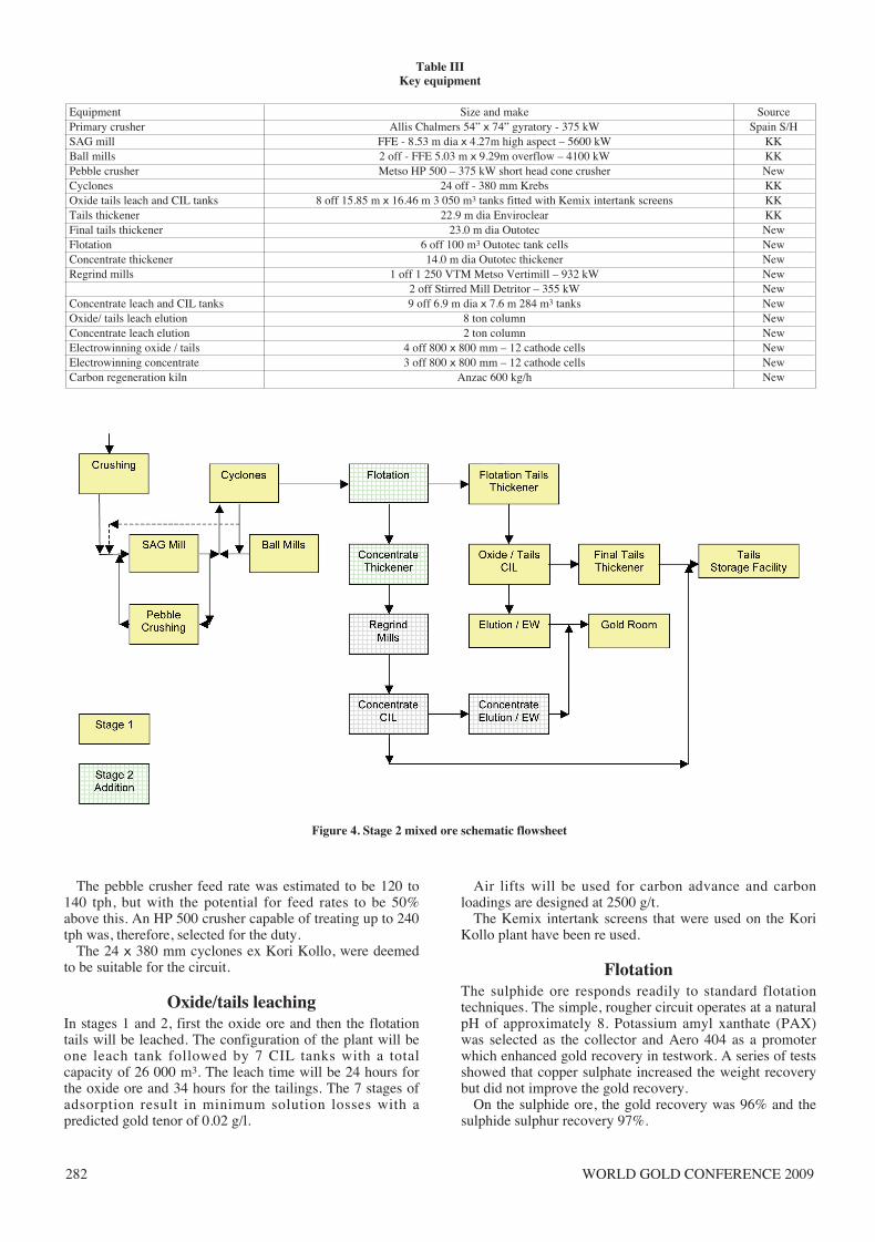
The oxide circuit was based on the use of the Kori Kollo plant and the difference with mixedore was that the oxide circuit would treat flotation tailings rather than ore. This circuit has a leachcapacity of 26 000 m3 and residence time of 24 hrs
The main feature of the upgraded mixed ore plant was the addition of a flotation circuit toproduce a concentrate which would be reground and treated in a separate leach and elution circuit.
Ore is crushed in a gyratory crusher and the comminution circuit uses a conventional SABCproducing a product with a P80 of 150 microns. The throughput of 580 tph of oxide ore and 500tph of mixed ore was set to match the mills from Kori Kollo, with the addition of the pebblecrusher to accommodate the more competent Sukari ore.
The flotation circuit comprises a single rougher circuit to maximize recovery. The concentrate isthickened prior to regrinding which is carried out in a tower mill and two SMD mills operating inseries. The final product, with a P80 of 12 microns, from the regrind circuit is leached in a CILcircuit with a total capacity of 2 550 m3. Gold is recovered through a conventional pressure Zadracircuit.
Tailings from both circuits report to separate tailings thickeners and are pumped to a tailingsstorage facility. The circuit is designed to maximize the recovery of water.
The project lies in one of the driest deserts in the world and a feature of the operation is the useof sea water from the Red Sea. This water is pumped 25 km from the coast.
Paper 75:text 10/16/09 9:05 AM Page 279
WORLD GOLD CONFERENCE 2009280
MineralogySamples of the ore used for metallurgical testwork wereexamined to determine the nature of the gold and sulphideminerals. The conclusions drawn were:
• Sulphide minerals are present with an average sulphurcontent of 1%
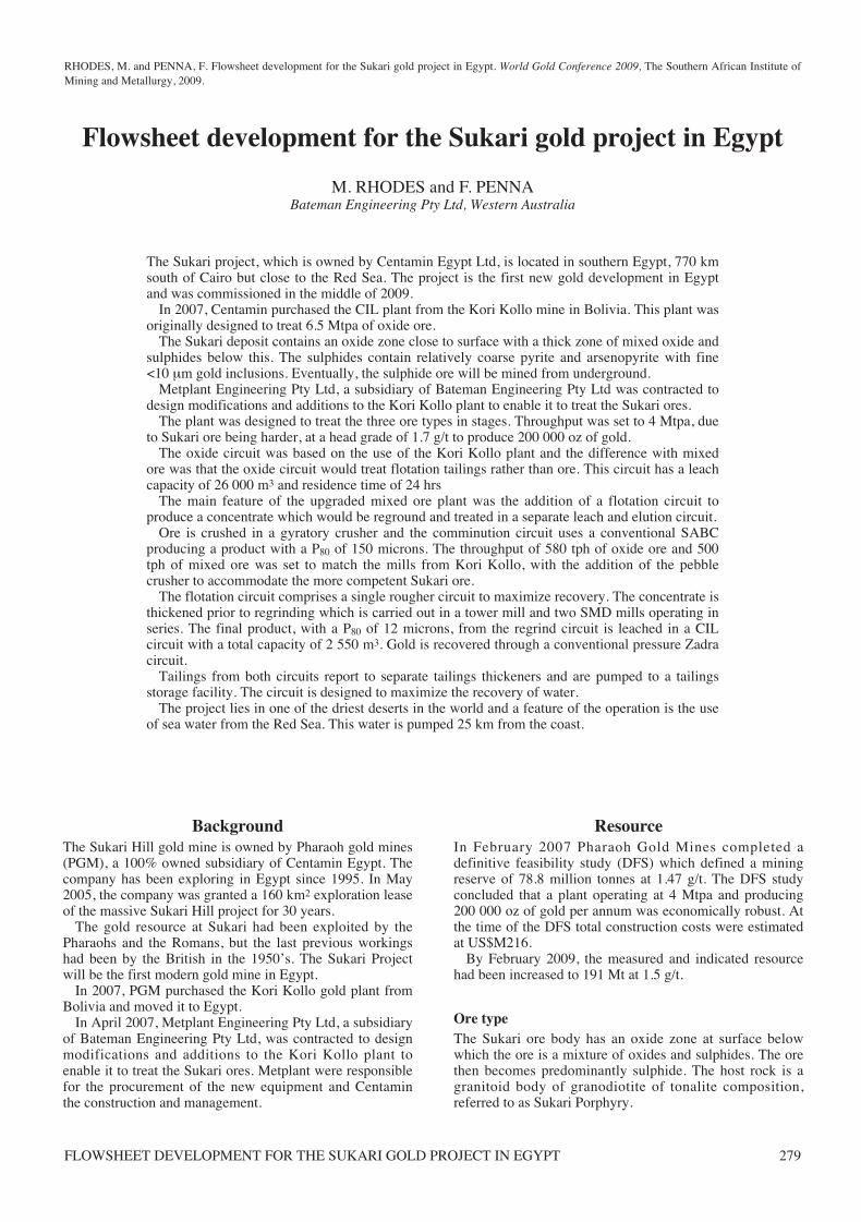
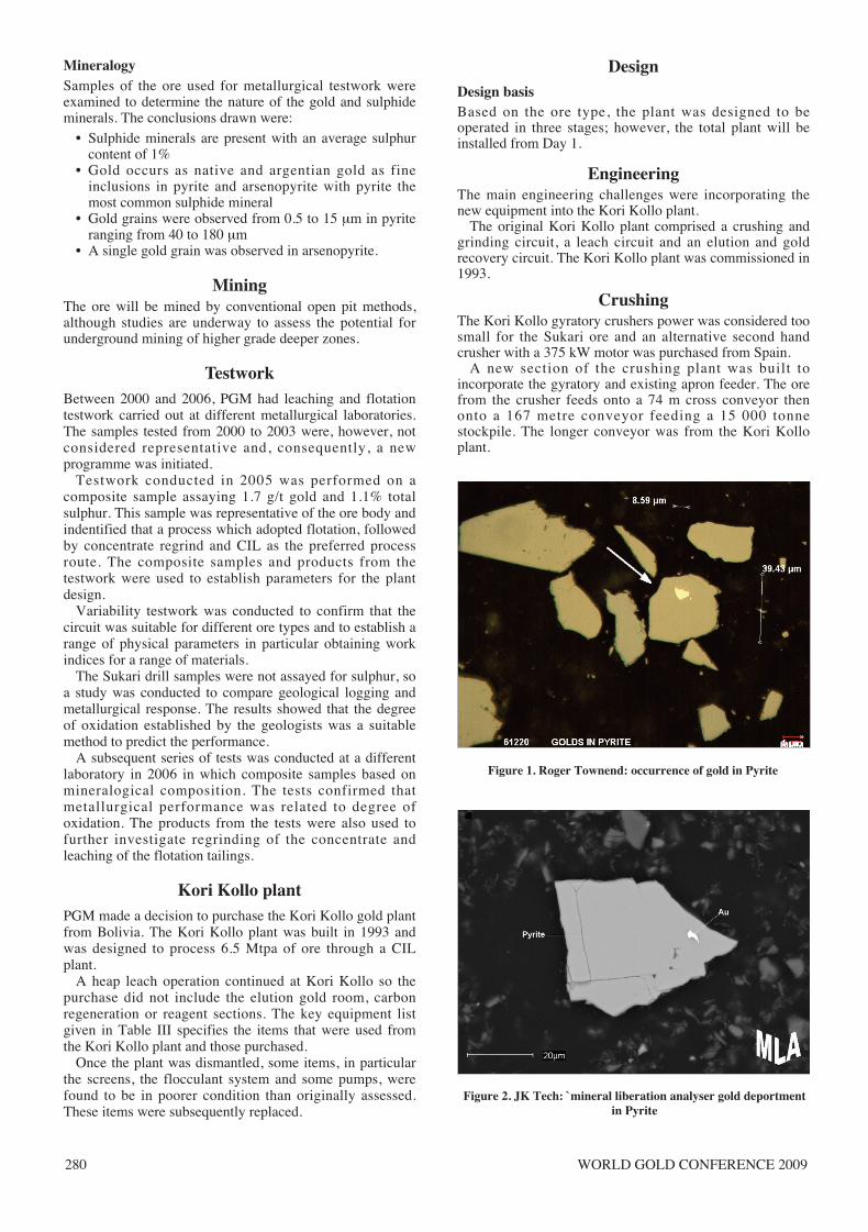
• Gold occurs as native and argentian gold as fineinclusions in pyrite and arsenopyrite with pyrite themost common sulphide mineral
• Gold grains were observed from 0.5 to 15 μm in pyriteranging from 40 to 180 μm
• A single gold grain was observed in arsenopyrite.
MiningThe ore will be mined by conventional open pit methods,although studies are underway to assess the potential forunderground mining of higher grade deeper zones.
TestworkBetween 2000 and 2006, PGM had leaching and flotationtestwork carried out at different metallurgical laboratories.The samples tested from 2000 to 2003 were, however, notconsidered representative and, consequently, a newprogramme was initiated.
Testwork conducted in 2005 was performed on acomposite sample assaying 1.7 g/t gold and 1.1% totalsulphur. This sample was representative of the ore body andindentified that a process which adopted flotation, followedby concentrate regrind and CIL as the preferred processroute. The composite samples and products from thetestwork were used to establish parameters for the plantdesign.
Variability testwork was conducted to confirm that thecircuit was suitable for different ore types and to establish arange of physical parameters in particular obtaining workindices for a range of materials.
The Sukari drill samples were not assayed for sulphur, soa study was conducted to compare geological logging andmetallurgical response. The results showed that the degreeof oxidation established by the geologists was a suitablemethod to predict the performance.
A subsequent series of tests was conducted at a differentlaboratory in 2006 in which composite samples based onmineralogical composition. The tests confirmed thatmetallurgical performance was related to degree ofoxidation. The products from the tests were also used tofurther investigate regrinding of the concentrate andleaching of the flotation tailings.
Kori Kollo plantPGM made a decision to purchase the Kori Kollo gold plantfrom Bolivia. The Kori Kollo plant was built in 1993 andwas designed to process 6.5 Mtpa of ore through a CILplant.
A heap leach operation continued at Kori Kollo so thepurchase did not include the elution gold room, carbonregeneration or reagent sections. The key equipment listgiven in Table III specifies the items that were used fromthe Kori Kollo plant and those purchased.
Once the plant was dismantled, some items, in particularthe screens, the flocculant system and some pumps, werefound to be in poorer condition than originally assessed.These items were subsequently replaced.
DesignDesign basisBased on the ore type, the plant was designed to beoperated in three stages; however, the total plant will beinstalled from Day 1.
EngineeringThe main engineering challenges were incorporating thenew equipment into the Kori Kollo plant.
The original Kori Kollo plant comprised a crushing andgrinding circuit, a leach circuit and an elution and goldrecovery circuit. The Kori Kollo plant was commissioned in1993.
CrushingThe Kori Kollo gyratory crushers power was considered toosmall for the Sukari ore and an alternative second handcrusher with a 375 kW motor was purchased from Spain.
A new section of the crushing plant was built toincorporate the gyratory and existing apron feeder. The orefrom the crusher feeds onto a 74 m cross conveyor thenonto a 167 metre conveyor feeding a 15 000 tonnestockpile. The longer conveyor was from the Kori Kolloplant.
Figure 1. Roger Townend: occurrence of gold in Pyrite
Figure 2. JK Tech: `mineral liberation analyser gold deportmentin Pyrite
Paper 75:text 10/16/09 9:05 AM Page 280
FLOWSHEET DEVELOPMENT FOR THE SUKARI GOLD PROJECT IN EGYPT 281
GrindingThe Sukari ore is harder than the Kori Kollo ore.Consequently a number of changes resulted. The grindingcircuit was modeled by SMCC Ltd.
The work index of 19.1 kWh/t for mixed and sulphideores was established at the 85th percentile of the resultsfrom a range of different rock types.
One of the samples tested was a sample designatedweathered ore. The work index of this material, at 16.2kWh/t, was used as the figure for oxide ore.
The feed to the grinding circuit was established at an 80%passing 113 mm based on the size of the product from thegyratory and the product P80 150 microns derived from theleach and flotation testwork.
• A decision was made to use the grinding circuit withoutany additional milling capacity. This restricted thethroughput to 4 Mtpa of mixed and sulphide ore. Thisthroughput served as the basis for the DFS study in2007
• A pebble crusher was required in the circuit to breakthe more competent scats from the SAG mill
• As the oxide ore is softer, the throughput will beincreased to 4.6 Mtpa in stage 1.
To achieve the required throughput the SAG mill ballload was set at 15% and the pebble port size was increasedto 80 mm. The mill manufacturer FFE (now FL Smidth)confirmed that the mill could be operated with a 15%charge.
Table IKey process design criteria
Criteria Units Stage 1 Stage 2 Stage 3Throughput Mtpa 4.6 4.0 4.0Throughput tph 580 500 500Plant availability % 91.3 91.3 91.3Head grade g/t Au 1.55 1.76 1.83ComminutionCrushing work index - range kWh/t 4.3 - 40 4.3 - 40 4.3 - 40Rod mill work index - design kWh/t 23.2 23.2 23.2Ball mill work index - design kWh/t 16.2 19.1 19.1
Cyclone overflow P80 μm 150 150 150Cyclone overflow solids density % 43 42 42
Concentrate regrind P80 μm N/A 12 12FlotationFeed solids density % N/A 35 35Residence time min N/A 32 32Concentrate production - average t/h N/A 25 25Concentrate production - design t/h N/A 40 40Gold recovery % N/A 71 96Collector - PAX g/t N/A 75 75Promoter – A404 g/t N/A 50 50Frother g/t N/A 20 20LeachOxide / flotation tails leach / hrs 24 34 N/ACIL residence timeFlotation concentrate leach / hrs N/A 43 43CIL residence timeNaCN – oxide / tails kg/t 1.74 0.6NaCN – concentrate kg/t 3.35 3.35DewateringOxide / tails specific settling rate t/m2/h 1.4 1.4 1.4Concentrate specific settling rate t/m2/h N/A 0.25 0.25Flocculant addition - total g/t 20 20 20
Table IIPredicted metallurgy
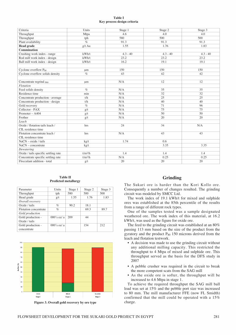
Parameter Units Stage 1 Stage 2 Stage 3Throughput tph 580 500 500Head grade g/t 1.55 1.76 1.83Overall recoveryOxide / tails % 90.2 18.1Flotation concentrate % 69.3 89.7Gold productionGold production - 000’s oz/ a 209 44Oxide / tailsGold production - 000’s oz/ a 154 212concentrate
Figure 3. Overall gold recovery by ore type
Paper 75:text 10/16/09 9:05 AM Page 281
WORLD GOLD CONFERENCE 2009282
The pebble crusher feed rate was estimated to be 120 to140 tph, but with the potential for feed rates to be 50%above this. An HP 500 crusher capable of treating up to 240tph was, therefore, selected for the duty.
The 24 x 380 mm cyclones ex Kori Kollo, were deemedto be suitable for the circuit.
Oxide/tails leachingIn stages 1 and 2, first the oxide ore and then the flotationtails will be leached. The configuration of the plant will beone leach tank followed by 7 CIL tanks with a totalcapacity of 26 000 m3. The leach time will be 24 hours forthe oxide ore and 34 hours for the tailings. The 7 stages ofadsorption result in minimum solution losses with apredicted gold tenor of 0.02 g/l.
Air lifts will be used for carbon advance and carbonloadings are designed at 2500 g/t.
The Kemix intertank screens that were used on the KoriKollo plant have been re used.
FlotationThe sulphide ore responds readily to standard flotationtechniques. The simple, rougher circuit operates at a naturalpH of approximately 8. Potassium amyl xanthate (PAX)was selected as the collector and Aero 404 as a promoterwhich enhanced gold recovery in testwork. A series of testsshowed that copper sulphate increased the weight recoverybut did not improve the gold recovery.
On the sulphide ore, the gold recovery was 96% and thesulphide sulphur recovery 97%.
Table IIIKey equipment
Equipment Size and make SourcePrimary crusher Allis Chalmers 54” x 74” gyratory - 375 kW Spain S/HSAG mill FFE - 8.53 m dia x 4.27m high aspect – 5600 kW KKBall mills 2 off - FFE 5.03 m x 9.29m overflow – 4100 kW KKPebble crusher Metso HP 500 – 375 kW short head cone crusher NewCyclones 24 off - 380 mm Krebs KKOxide tails leach and CIL tanks 8 off 15.85 m x 16.46 m 3 050 m3 tanks fitted with Kemix intertank screens KKTails thickener 22.9 m dia Enviroclear KKFinal tails thickener 23.0 m dia Outotec NewFlotation 6 off 100 m3 Outotec tank cells NewConcentrate thickener 14.0 m dia Outotec thickener NewRegrind mills 1 off 1 250 VTM Metso Vertimill – 932 kW New
2 off Stirred Mill Detritor – 355 kW NewConcentrate leach and CIL tanks 9 off 6.9 m dia x 7.6 m 284 m3 tanks NewOxide/ tails leach elution 8 ton column NewConcentrate leach elution 2 ton column NewElectrowinning oxide / tails 4 off 800 x 800 mm – 12 cathode cells NewElectrowinning concentrate 3 off 800 x 800 mm – 12 cathode cells NewCarbon regeneration kiln Anzac 600 kg/h New
Figure 4. Stage 2 mixed ore schematic flowsheet
Paper 75:text 10/16/09 9:05 AM Page 282
FLOWSHEET DEVELOPMENT FOR THE SUKARI GOLD PROJECT IN EGYPT 283
Weight recoveryThe average mass pull at a head grade of 1% sulphur was5% which equates to 25 tph. The maximum design was setat an 8% pull which was based on a sulphur grade of 1.8%which was at the 90th percentile of core assays. Thisthroughput was most significant in sizing the regrind millcircuit.
The gold grade of the concentrate was 25 and 35 g/t forstages 2 and 3, respectively. The copper of the concentrateis below 200 ppm so the cyanide consumption will not beaffected.
FrotherThe original frother selected for the process was methylisobutyl carbinol (MIBC). As MIBC has a flash point of43°C it requires additional safety measures includingexplosion proof motors and switches to be employed whendesigning the reagent circuit. Tests conducted with alternatefrothers showed that Huntsman Polyfroth W22 gave anequivalent result to MIBC. W22 has a flash point of 71°Cand, therefore, was selected as the installation cost wasreduced and safety enhanced.
Leaching of flotation tailingsThe residue grade from the flotation averaged 0.5 g/t Au.The tailings were subject to cyanidation. The testworkshowed that an economical recovery of 71% could beachieved in 24 hours.
RegrindingThe gold is finely encapsulated, but not in solid solution,therefore, regrinding was investigated as the method forimproving the recovery from the sulphides.
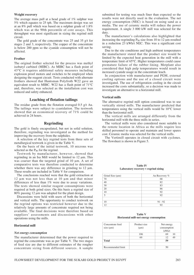
A selection of the key regrind tests from three sets ofmetallurgical testwork is given in the Table V.
On the basis of the initial testwork, 10 microns wasselected as the P80 for the regrind.
Testwork by manufacturer, however, showed thatregrinding in an Isa Mill would be limited to 12 μm. Thiswas coarser than the targeted grind of 10 μm. A set ofcomparative tests was therefore conducted to determinewhether there was any difference in grinding to 12 μm.These results are included in Table V for comparison.
The conclusions reached were that the gold extraction at12 μm was not less than at 10 μm and that minordifferences of less than 1% were due to assay variations.The tests showed similar reagent consumptions wererequired at both grind sizes. On this basis a regrind size of80% passing 12 μm was adopted for the plant design.
Discussions were held with users of both the horizontaland vertical mills. The opportunity to conduct testwork onthe regrind options was restricted however due to therelatively large amounts of concentrate required not beingavailable. The final decisions were therefore based onsuppliers’ assessments and discussions with otheroperations using the mills.
Horizontal mill
Net energy consumptionThe manufacturer determined that the power required toregrind the concentrate was as per Table V. The two stagesof feed size are due to different estimates of the rougherconcentrate sizing from different sources. A sample
submitted for testing was much finer than expected so theresults were not directly used in the evaluation. The netenergy consumption (NEC) is based on using sand as amedia. The use of ceramic media will reduce the powerrequirement. A single 3 000 kW mill was selected for theduty.
The manufacturer’s calculations also highlighted thatincreasing the regrinding P80 size from 10 to 12 μm resultedin a reduction 23 kWh/t NEC. This was a significant costsaving.
Due to the site conditions and high ambient temperaturesthe manufacturer stated that the product size would belimited by the expected heat generation in the mill with atemperature limit of 65°C. Higher temperatures could causepremature failure of the rubber lining. Metplant alsoconsidered that high pulp temperatures would result inincreased cyanide usage in the concentrate leach.
In conjunction with manufacturer and PGM, externalcooling options and the use of a closed circuit wereinvestigated. The use of refrigeration cooling in the circuitincreased the costs substantially, so a decision was made toinvestigate an alternative to a horizontal mill.
Vertical millsThe alternative regrind mill option considered was to usevertically stirred mills. The manufacturer predicted thattemperatures using the vertical mills would be 10°C lowerthan the horizontal mill.
The vertical mills are arranged differently from thehorizontal mill with the three mills in series.
The vertical mills were also considered more suitable tothe remote location in Africa as the mills require lessskilled personnel to operate and maintain and lower sparescost. Ceramic media was selected for the vertical mills.
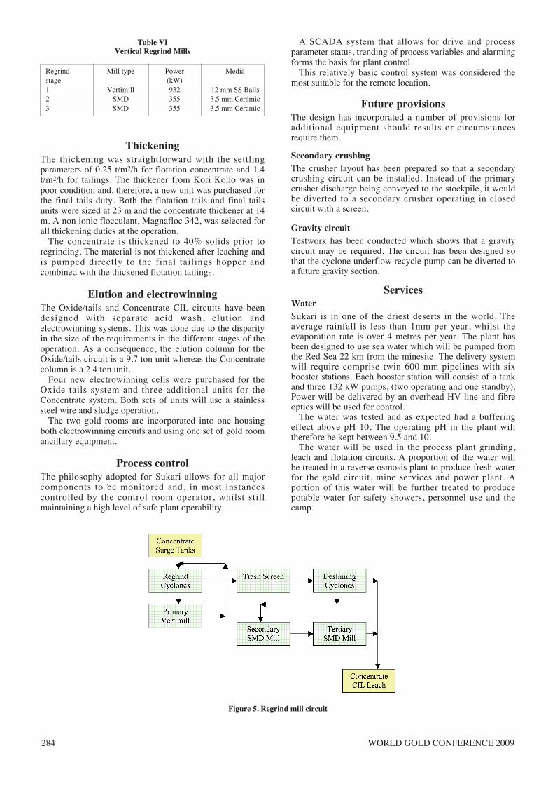
The Vertimill operates in closed circuit with cyclones.The flowsheet is shown in Figure 5.
Table VHorizontal mill–net energy consumption
Concentrate feed Product size Net energy size (μm) (μm) consumption
kWh/t106 69 1069 12 49
Total 59
Recommended limit 50
Table IVLaboratory recovery v regrind sizing
Grind Size (μm) Au Recovery %70 6840 8230 8320 8610 925 92
10 91 - 9212 92
Paper 75:text 10/16/09 9:05 AM Page 283
WORLD GOLD CONFERENCE 2009284
ThickeningThe thickening was straightforward with the settlingparameters of 0.25 t/m2/h for flotation concentrate and 1.4t/m2/h for tailings. The thickener from Kori Kollo was inpoor condition and, therefore, a new unit was purchased forthe final tails duty. Both the flotation tails and final tailsunits were sized at 23 m and the concentrate thickener at 14m. A non ionic flocculant, Magnafloc 342, was selected forall thickening duties at the operation.
The concentrate is thickened to 40% solids prior toregrinding. The material is not thickened after leaching andis pumped directly to the final tailings hopper andcombined with the thickened flotation tailings.
Elution and electrowinningThe Oxide/tails and Concentrate CIL circuits have beendesigned with separate acid wash, elution andelectrowinning systems. This was done due to the disparityin the size of the requirements in the different stages of theoperation. As a consequence, the elution column for theOxide/tails circuit is a 9.7 ton unit whereas the Concentratecolumn is a 2.4 ton unit.
Four new electrowinning cells were purchased for theOxide tails system and three additional units for theConcentrate system. Both sets of units will use a stainlesssteel wire and sludge operation.
The two gold rooms are incorporated into one housingboth electrowinning circuits and using one set of gold roomancillary equipment.
Process controlThe philosophy adopted for Sukari allows for all majorcomponents to be monitored and, in most instancescontrolled by the control room operator, whilst stillmaintaining a high level of safe plant operability.
A SCADA system that allows for drive and processparameter status, trending of process variables and alarmingforms the basis for plant control.
This relatively basic control system was considered themost suitable for the remote location.
Future provisionsThe design has incorporated a number of provisions foradditional equipment should results or circumstancesrequire them.
Secondary crushingThe crusher layout has been prepared so that a secondarycrushing circuit can be installed. Instead of the primarycrusher discharge being conveyed to the stockpile, it wouldbe diverted to a secondary crusher operating in closedcircuit with a screen.
Gravity circuitTestwork has been conducted which shows that a gravitycircuit may be required. The circuit has been designed sothat the cyclone underflow recycle pump can be diverted toa future gravity section.
ServicesWater Sukari is in one of the driest deserts in the world. Theaverage rainfall is less than 1mm per year, whilst theevaporation rate is over 4 metres per year. The plant hasbeen designed to use sea water which will be pumped fromthe Red Sea 22 km from the minesite. The delivery systemwill require comprise twin 600 mm pipelines with sixbooster stations. Each booster station will consist of a tankand three 132 kW pumps, (two operating and one standby).Power will be delivered by an overhead HV line and fibreoptics will be used for control.
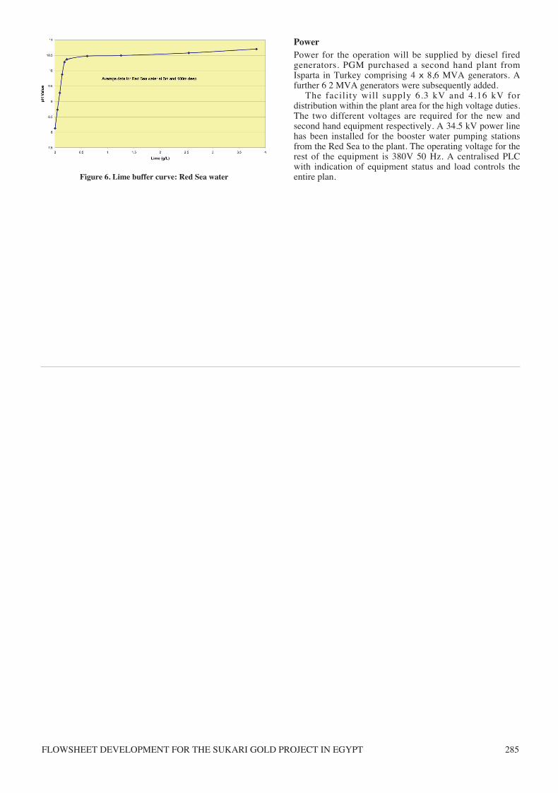
The water was tested and as expected had a bufferingeffect above pH 10. The operating pH in the plant willtherefore be kept between 9.5 and 10.
The water will be used in the process plant grinding,leach and flotation circuits. A proportion of the water willbe treated in a reverse osmosis plant to produce fresh waterfor the gold circuit, mine services and power plant. Aportion of this water will be further treated to producepotable water for safety showers, personnel use and thecamp.
Table VIVertical Regrind Mills
Regrind Mill type Power Mediastage (kW)1 Vertimill 932 12 mm SS Balls2 SMD 355 3.5 mm Ceramic3 SMD 355 3.5 mm Ceramic
Figure 5. Regrind mill circuit
Paper 75:text 10/16/09 9:05 AM Page 284
FLOWSHEET DEVELOPMENT FOR THE SUKARI GOLD PROJECT IN EGYPT 285
Power Power for the operation will be supplied by diesel firedgenerators. PGM purchased a second hand plant fromIsparta in Turkey comprising 4 x 8,6 MVA generators. Afurther 6 2 MVA generators were subsequently added.
The facility will supply 6.3 kV and 4.16 kV fordistribution within the plant area for the high voltage duties.The two different voltages are required for the new andsecond hand equipment respectively. A 34.5 kV power linehas been installed for the booster water pumping stationsfrom the Red Sea to the plant. The operating voltage for therest of the equipment is 380V 50 Hz. A centralised PLCwith indication of equipment status and load controls theentire plan. Figure 6. Lime buffer curve: Red Sea water
Paper 75:text 10/16/09 9:05 AM Page 285

WORLD GOLD CONFERENCE 2009286
Paper 75:text 10/16/09 9:05 AM Page 286