fluid couplings - sytrans · fluid couplings english. w e s t c a r milano ... rotogear tooth gear...
TRANSCRIPT
WE
S T C AR
MILANOITALY
s.r.l.
FLUID COUPLINGS
ENGLISH
WESTCA
R
MILANOITALY
PRODOTTI WESTCAR
A RICHIESTA SI POSSONOFORNIRE I PRODOTTI
CERTIFICATI ATEX.
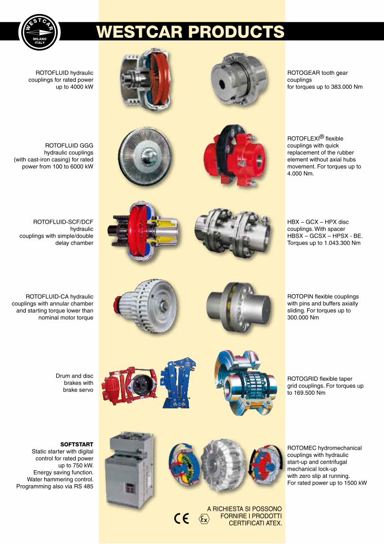
ROTOFLUID-CA hydraulic couplings with annular chamber
and starting torque lower than nominal motor torque
SOFTSTARTStatic starter with digital
control for rated powerup to 750 kW.
Energy saving function.Water hammering control.
Programming also via RS 485
ROTOFLUID GGGhydraulic couplings
(with cast-iron casing) for rated power from 100 to 6000 kW
ROTOFLUID hydraulic couplings for rated power
up to 4000 kW
ROTOFLUID-SCF/DCF hydraulic
couplings with simple/double delay chamber
Drum and discbrakes withbrake servo
ROTOMEC hydromechanical couplings with hydraulicstart-up and centrifugal mechanical lock-upwith zero slip at running.For rated power up to 1500 kW
ROTOPIN flexible couplingswith pins and buffers axially sliding. For torques up to 300.000 Nm
ROTOFLEXI® flexiblecouplings with quick replacement of the rubber element without axial hubs movement. For torques up to 4.000 Nm.
ROTOGEAR tooth gear couplingsfor torques up to 383.000 Nm
HBX – GCX – HPX disc couplings. With spacerHBSX – GCSX – HPSX - BE.Torques up to 1.043.300 Nm
ROTOGRID flexible tapergrid couplings. For torques up to 169.500 Nm
WESTCAR PRODUCTS
MILANO - ITALYW
E
S T C A
R
MILANOITALY
Sheet
Date
ROTOFLUID CATALOGUECode 13906 - Issued : 07-2006 ENGLISH (Rev. 2)
10-056B EN
09-2006
TABLE OF CONTENTS ..............................................................................PAGE Operating principles and features of ROTOFLUID couplings ..........................................................2
Electric motor characteristic curves with and without fluid coupling ................................................3
Fluid couplings with delay chamber .................................................................................................4
Characteristic starting curves ..........................................................................................................5
ROTOFLUID coupling selection diagram .........................................................................................6
ROTOFLUID coupling selection table for 50 Hz, 60 Hz UNEL MEC electric motors .......................7
Performance calculation .............................................................................................................. 8-9
ROTOFLUID couplings moments of inertia ...................................................................................10
ROTOFLUID ALFA - coupling for in line versions ....................................................................11
Installation options ........................................................................................................................12
ROTOFLUID selection with recommended flexible coupling for standard electric motors .............13
Table ROTOFLUID ALFA “K” ........................................................................................................14
Table ROTOFLUID ALFA “SCF K” ................................................................................................15
Table ROTOFLUID ALFA “DCF K” ................................................................................................16
Table ROTOFLUID ALFA “K-S” “SCF K-S” “DCF K-S” .................................................................17
Table ROTOFLUID ALFA “K-LRV” “SCF K-LRV” “DCF K-LRV” ......................................................18
Table ROTOFLUID ALFA “K-LRU” “SCF K-LRU” “DCF K-LRU” .................................................... 19
Table ROTOFLUID ALFA “K-FRV” “SCF K-FRV” “DCF K-FRV” ....................................................20
Table ROTOFLUID ALFA “K-FRU” “SCF K-FRU” “DCF K-FRU” ...................................................21
Table ROTOFLUID ALFA “K-AB” “SCF K-AB” “DCF K-AB” ...........................................................22
Table ROTOFLUID ALFA “K-FRD” “SCF K-FRD” “DCF K-FRD” ....................................................23
Table ROTOFLUID ALFA “K-AFF” “SCF K-AFF” “DCF K-AFF” ......................................................24
Table ROTOFLUID ALFA “K-FR-PAV” “SCF K-PAV” “DCF K-PAV” .................................................25
Table ROTOFLUID ALFA “KK” “SCF KK” “DCF KK” ................................................................ 26-27
Brake drum “FP” for ROTOFLUID ALFA “KK” ......................................................................... 28-29
Table ROTOFLUID ALFA “WAG” “SCF WAG” “DCF WAG” ...........................................................30
Table ROTOFLUID ALFA “WAG-G” “SCF WAG-G” “DCF WAG-G” ...............................................31
Table ROTOFLUID ALFA “CK-LRS” ..............................................................................................32
ROTOFLUID coupling ALFA “K-SS” .............................................................................................33
ROTOFLUID BETA - coupling for pulley versions ...................................................................34
Mounting examples with ROTOFLUID couplings BETA pulley versions ........................................35
Table ROTOFLUID BETA “X” .................................................................................................. 36-37
Table ROTOFLUID BETA “J” ................................................................................................... 38-39
Table ROTOFLUID BETA “H” .........................................................................................................40
Table ROTOFLUID BETA “Z”-“ZI”...................................................................................................41
Bore dimensions table for ROTOFLUID coupling ..........................................................................42
Bore dimensions for flexible coupling and brake drum hubs .........................................................43
ROTOFLUID coupling instructions for replacement and variation of the oil quantity ..............44
ROTOFLUID coupling scf / dcf instructions for replacement and variation of the oil quantity ..45
Fusible Plug ..................................................................................................................................46
Thermal trip plug ..........................................................................................................................47
Electric - thermal – switch equipment type “ET” ...........................................................................48
Electronic “scd” device for overload control ...............................................................................49
Instructions for mounting rotofluid coupling on the motor shaft ................................................50
Instructions for pulling off rotofluid coupling from the motor shaft ........................................ 51
Screw puller “VE” type - pulling off system “SE” type ..................................................................51
ROTOFLUID couplings outline and main components .............................................................52
Recommended spare parts ........................................................................................................53
Optional functions ..........................................................................................................................54
Application requirements ...............................................................................................................55
Fields of application ......................................................................................................................56
1
INDEX OF TECH SHEETS
10-137A** ............................210-002B** ..............................710-013A** ...........................4410-016A** ...........................4510-019D** ...........................4210-023A** ...........................4310-030A** ..............................810-031A** ..............................910-035A** ...........................1010-040A** ...........................1310-047A** ...........................3410-052A** ................. 5610-057B** ...........................1110-059A** ...........................5510-060A** ...........................5410-061A** ..............................310-080A** ..............................510-100A** ..............................610-138A** ...........................1210-141A** ..............................410-142A** ...........................3540-010B** ...........................1440-050A** ...........................3340-280A** ...........................3245-042B** ...........................1845-020B** ...........................1745-043B** ...........................1945-060B** ...........................2045-062A** ...........................2145-066B** ...........................2545-070B** ...........................2345-081B** ...........................2245-082B** ...........................2645-083B** ...........................2745-092B** ...........................2445-112B** ...........................3045-113D** ...........................3145-204A** ...........................4145-210A** ...........................3845-211C** ...........................3945-220A** ...........................4045-250A** ...........................3645-251B** ...........................3750-010B** ...........................1652-006B** ...........................1570-006B** ...........................2870-007B** ...........................2980-002A** ...........................4680-003A** ...........................4780-004A** ...........................4880-022A** ...........................4990-004A** ...........................5090-005A** ...........................5190-018A** ...........................5290-022A** ...........................53
MILANO - ITALYW
E
S T C A
R
MILANOITALY
Sheet
Date
OPERATING PRINCIPLES AND FEATURES OF ROTOFLUID COUPLINGS
10-137A EN
05-2006
2
LATO MOTORE
PARTECONDOTTA
PARTEMOTRICE
OIL
OIL
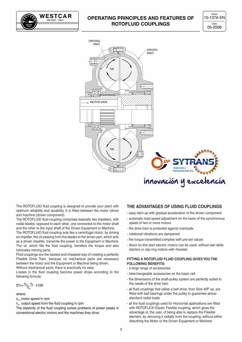
THE ADVANTAGES OF USING FLUID COUPLINGS- easy start-up with gradual acceleration of the driven component
- automatic load speed adjustment on the basis of the synchronous speed of two or more motors
- the drive train is protected against overloads
- rotational vibrations are dampened
- the torque transmitted complies with pre-set values
- direct on-line start electric motors can be used, without star-delta starters or slip-ring motors with rheostat
FITTING A ROTOFLUID FLUID COUPLING GIVES YOU THE FOLLOWING BENEFITS:- a large range of accessories
- interchangeable accessories on the basic cell
- the dimensions of the shaft-pulley system are perfectly suited to the needs of the drive train
- all fluid couplings that utilise a belt drive, from Size 40P up, are fitted with ball bearings under the pulley to guarantee above-standard radial loads
- all the fluid couplings used for Horizontal applications are fitted with ROTOFLEXI Elastic Flexible coupling, which gives the advantage of, the user, of being able to replace the Flexible element, by removing it radially from the coupling, without either disturbing the Motor or the Driven Equipment or Machine
DRIVING PART
DRIVEN PART
MOTOR SIDE
The ROTOFLUID fluid coupling is designed to provide your plant with optimum reliability and durability. It is fitted between the motor (drive) and machine (driven component).The ROTOFLUID fluid coupling comprises basically two impellers, with radial blades, opposed to each other, one connected to the motor shaft and the other to the input shaft of the Driven Equipment or Machine.The ROTOFLUID fluid coupling acts like a centrifugal clutch, by driving an impeller, the oil passing from the blades to the driven part, which acts as a driven impeller, transmits the power to the Equipment or Machine.The oil, which fills the fluid coupling, transfers the torque and also lubricates moving parts.Fluid couplings are the easiest and cheapest way of creating a perfectly Flexible Drive Train, because no mechanical parts are necessary between the motor and the Equipment or Machine being driven.Without mechanical parts, there is practically no wear.Losses in the fluid coupling become power drops according to the following formula:
S%= nm - nu x100nm
where:nm= motor speed in rpmnu= output speed from the fluid coupling in rpmThe elasticity of the fluid coupling solves problems of power peaks in conventional electric motors and the machines they drive.
MILANO - ITALYW
E
S T C A
R
MILANOITALY
Sheet
Date
ELECTRIC MOTOR CHARACTERISTIC CURVESWITH AND WITHOUT FLUID COUPLING
10-061A EN
05-2006
3
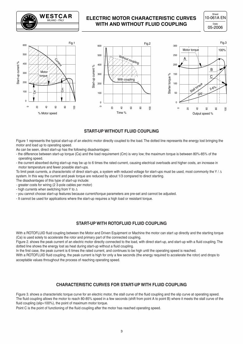
START-UP WITHOUT FLUID COUPLING
Figure 1 represents the typical start-up of an electric motor directly coupled to the load. The dotted line represents the energy lost bringing the motor and load up to operating speed.As can be seen, direct start-up has the following disadvantages:- the difference between start-up torque (Ca) and the load requirement (Cm) is very low; the maximum torque is between 80%-85% of the
operating speed.- the current absorbed during start-up may be up to 6 times the rated current, causing electrical overloads and higher costs, an increase in
motor temperature and fewer possible start-ups.To limit peak currents, a characteristic of direct start-ups, a system with reduced voltage for start-ups must be used, most commonly the Y / ∆ system. In this way the current and peak torque are reduced by about 1/3 compared to direct starting.The disadvantages of this type of start-up include:- greater costs for wiring (2 3-pole cables per motor)- high currents when switching from Y to ∆- you cannot choose start-up features because current/torque parameters are pre-set and cannot be adjusted.- It cannot be used for applications where the start-up requires a high load or resistant torque.
START-UP WITH ROTOFLUID FLUID COUPLING
With a ROTOFLUID fluid coupling between the Motor and Driven Equipment or Machine the motor can start up directly and the starting torque (Ca) is used solely to accelerate the rotor and primary part of the connected coupling.Figure 2. shows the peak current of an electric motor directly connected to the load, with direct start-up, and start-up with a fluid coupling. The dotted line shows the energy lost as heat during start-up without a fluid coupling.In the first case, the peak current is 6 times the rated current, and continues to be high until the operating speed is reached.With a ROTOFLUID fluid coupling, the peak current is high for only a few seconds (the energy required to accelerate the rotor) and drops to acceptable values throughout the process of reaching operating speed.
CHARACTERISTIC CURVES FOR START-UP WITH FLUID COUPLING
Figure 3. shows a characteristic torque curve for an electric motor, the stall curve of the fluid coupling and the slip curve at operating speed.The fluid coupling allows the motor to reach 80-85% speed in a few seconds (shift from point A to point B) where it meets the stall curve of the fluid coupling (slip=100%), the point of maximum motor torque.Point C is the point of functioning of the fluid coupling after the motor has reached operating speed.
0
100
200
300
400
500
600
0 20 40 60 80 100
Sta
rt-u
p cu
rren
t %
% Motor speed
Fig.1
Ca C
m
Current
0
50
100
150
200
250
300
0 20 40 60 80 100
Sta
rter
torq
ue %
Output speed %
Fig.3
0
100
200
300
400
500
600
0
20 40 60 80 100
Sta
rt-u
p cu
rren
t %
Time %
Fig.2
Without coupling
Motor torque
With coupling
Slip2-6%
Motor torque
Stall torque
100%
A
B
C
MILANO - ITALYW
E
S T C A
R
MILANOITALY
Sheet
Date
FLUID COUPLINGS WITH DELAY CHAMBER
10-141A EN
05-2006
4
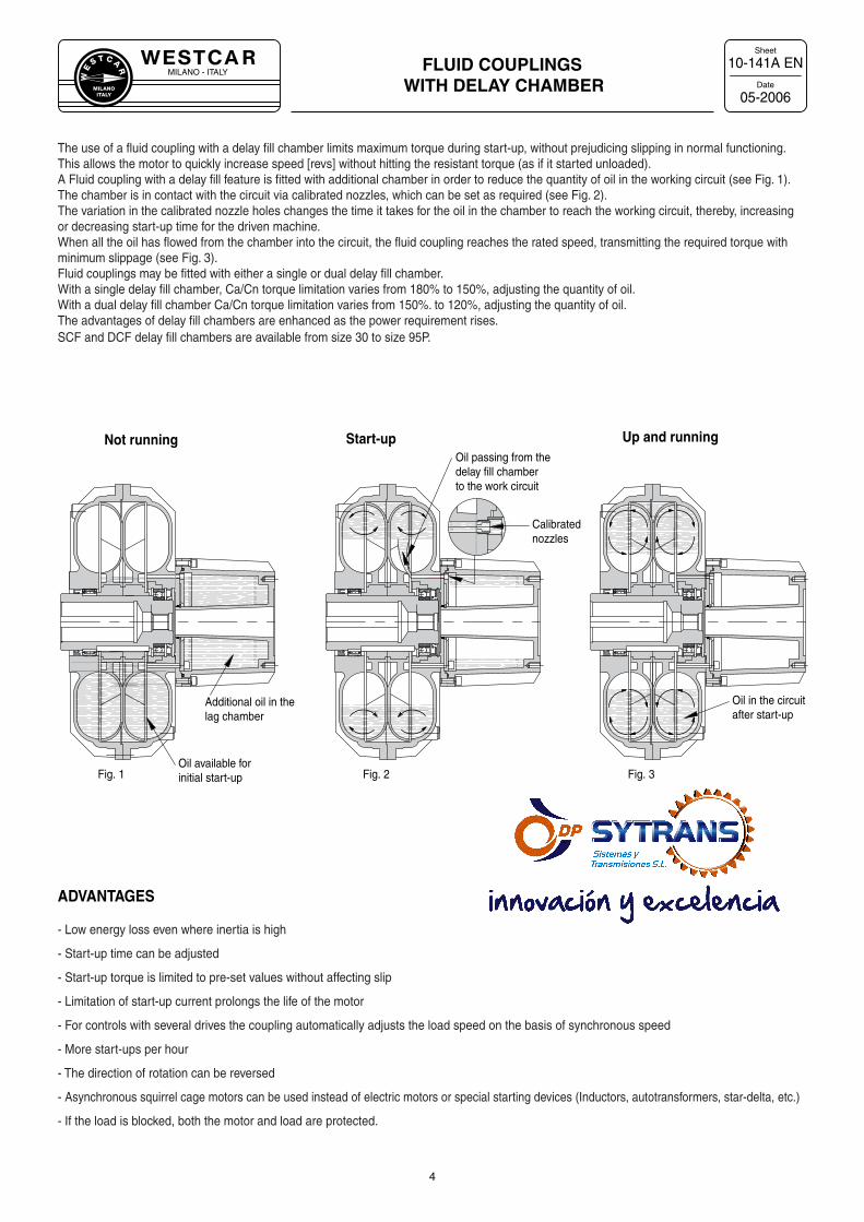
The use of a fluid coupling with a delay fill chamber limits maximum torque during start-up, without prejudicing slipping in normal functioning.This allows the motor to quickly increase speed [revs] without hitting the resistant torque (as if it started unloaded).A Fluid coupling with a delay fill feature is fitted with additional chamber in order to reduce the quantity of oil in the working circuit (see Fig. 1). The chamber is in contact with the circuit via calibrated nozzles, which can be set as required (see Fig. 2).The variation in the calibrated nozzle holes changes the time it takes for the oil in the chamber to reach the working circuit, thereby, increasing or decreasing start-up time for the driven machine.When all the oil has flowed from the chamber into the circuit, the fluid coupling reaches the rated speed, transmitting the required torque with minimum slippage (see Fig. 3).Fluid couplings may be fitted with either a single or dual delay fill chamber.With a single delay fill chamber, Ca/Cn torque limitation varies from 180% to 150%, adjusting the quantity of oil.With a dual delay fill chamber Ca/Cn torque limitation varies from 150%. to 120%, adjusting the quantity of oil.The advantages of delay fill chambers are enhanced as the power requirement rises.SCF and DCF delay fill chambers are available from size 30 to size 95P.
ADVANTAGES
- Low energy loss even where inertia is high
- Start-up time can be adjusted
- Start-up torque is limited to pre-set values without affecting slip
- Limitation of start-up current prolongs the life of the motor
- For controls with several drives the coupling automatically adjusts the load speed on the basis of synchronous speed
- More start-ups per hour
- The direction of rotation can be reversed
- Asynchronous squirrel cage motors can be used instead of electric motors or special starting devices (Inductors, autotransformers, star-delta, etc.)
- If the load is blocked, both the motor and load are protected.
Oil available forinitial start-up
Additional oil in thelag chamber
Oil passing from thedelay fill chamberto the work circuit
Oil in the circuitafter start-up
Not running
Fig. 1 Fig. 2 Fig. 3
Calibrated nozzles
Start-up Up and running
MILANO - ITALYW
E
S T C A
R
MILANOITALY
Sheet
Date
0 5 10 15
0 5 10 15
0 5 10 15
200%
100%
200%
100%
STARTING TIME (sec.)
STARTING TIME (sec.)
MOTOR TORQUE
MOTOR TORQUE
100%
200%
MOTOR TORQUE
ROTOFLUID COUPLING-DCF (with double delay chamber)
ROTOFLUID COUPLING-SCF (with single delay chamber)
ROTOFLUID COUPLING
TIME (sec.)
TIME (sec.)
TIME (sec.)
TOR
QU
ETO
RQ
UE
TOR
QU
E
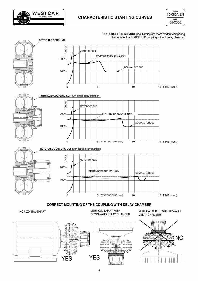
STARTING TORQUE 180÷200%
NOMINAL TORQUE
STARTING TORQUE 150÷180%
NOMINAL TORQUE
STARTING TORQUE 120÷150% NOMINAL TORQUE
YES YES
NO
HORIZONTAL SHAFT VERTICAL SHAFT WITH DOWNWARD DELAY CHAMBER
VERTICAL SHAFT WITH UPWARD DELAY CHAMBER
CHARACTERISTIC STARTING CURVES10-080A EN
05-2006
5
CORRECT MOUNTING OF THE COUPLING WITH DELAY CHAMBER
The ROTOFLUID SCF/DCF peculiarities are more evident comparing the curve of the ROTOFLUID coupling without delay chamber.
MILANO - ITALYW
E
S T C A
R
MILANOITALY
Sheet
Date
6
10-100A EN
05-2006
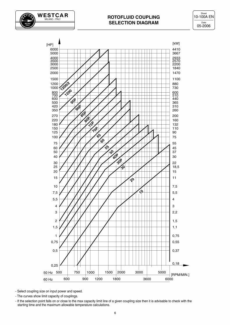
ROTOFLUID COUPLING SELECTION DIAGRAM
1000 30001500
0,25
0,5
1
0,75
1,5
3
2
4
7,5
5,5
10
600
20
15
2530
40506075
150
100125
180220270
350
500420
1000800700
12001500
20002500
[HP]
3000
50 Hz
0,37
0,75
0,55
1,1
2,2
1,5
3
5,5
4
7,5
440
15
11
18,522
30374555
110
7590
132160200
260
365310
730600510
8801100
14701840
[kW]
2200
0,18
[RPM/MIN.]
25703500
900 1200 1800 3600
750
60 Hz 600 6000
2000 5000500
40005000
29333667
6000 4410
10
20
3030
P40P
5055
6065
70P
75P80
P85
P90
P95
P
1200
/2
1200
- Select coupling size on input power and speed.- The curves show limit capacity of couplings.- If the selection point falls on or close to the max capacity limit line of a given coupling size then it is advisable to check with the
starting time and the maximum allowable temperature calculations.
MILANO - ITALYW
E
S T C A
R
MILANOITALY
Sheet
Date
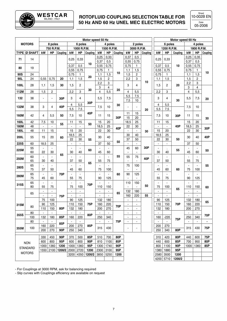
ROTOFLUID COUPLING SELECTION TABLE FOR 50 Hz AND 60 Hz UNEL MEC ELECTRIC MOTORS
10-002B EN
05-2006
7
MOTORSMotor speed 50 Hz Motor speed 60 Hz
8 poles 6 poles 4 poles 2 poles 6 poles 4 poles750 R.P.M. 1000 R.P.M. 1500 R.P.M. 3000 R.P.M. 1200 R.P.M. 1800 R.P.M.
TYPE Ø SHAFT kW HP Coupling kW HP Coupling kW HP Coupling kW HP Coupling kW HP Coupling kW HP Coupling
71 14 0,25 0,3310
0,25 0,33
10
0,37 0,5
10
0,25 0,33
10
0,25 0,35
10
0,37 0,5 0,55 0,75 0,37 0,5
80 190,37 0,5 0,55 0,75 0,75 1 0,37 0,5 0,55 0,750,55 0,75
20
0,75 1 1,1 1,5 0,55 0,75 0,75 190S 24 0,75 1 1,1 1,5 1,5 2 0,75 1 1,1 1,590L 24 0,55 0,75 20 1,1 1,5 1,5 2 2,2 3 1,1 1,5
20
1,5 2
100L 28 1,1 1,5 30 1,5 230
2,2 3
203 4 1,5 2
2,2 33 4 3 4
20
112M 28 1,5 2
30P
2,2 3 4 5,5 4 5,5 2,2 3 4 5,5
132 38 - - 3 430P
5,5 7,5
30
5,5 7,5
20
3 430
5,5 7,57,5 10
132M 38 3 4 40P4 5,5
7,5 10 - -4 5,5
7,5 10
30
5,5 7,540P
5,5 7,5
30P160M 42 4 5,5 50 7,5 10 11 1530P
11 157,5 10 11 15
15 20
30
160L 42 7,5 1055
11 1550
15 20 18,5 25 11 1540P
15 20180M 48 - - - - 18,5 25
40P22 30 - - 18,5 25
30P180L 48 11 15
60
15 20
55
22 30 - - 15 20 22 30
200L 55 15 2018,5 25
30 4050
30 40 18,5 2550
30 40 40P22 30 37 50
30P
22 30225S 60 18,5 25
65
- - 37 50 - - - - 37 50
50225M5560
-22
-30
-30
-40
60-
45-
6055
45-
60-
-30
.40
55-
45-
60
250M6065
-30
-40
-37
-50
65
-55
-75
55-
75-
40P-
37-
50
60
-55
-75
55280S6575
-37
-50
70P
-45
-60
-75
-100
60
75-
100-
50
-45
-60
-75
-100
280M6575
-45
-60
-55
-75
70P
-90
-125
90-
125-
-55
-75
-90
-125
60315S
6580
-55
-75
75P
-75
-100
-110
-150
65
110-
150-
-75
-100
65
-110
-150
315M
65- - - - - - 132 180 - - - -- - - - - - 160 220 55 - - - -
80
75 100 90 12575P
132 180 - - 90 12570P
132 18065
90 12580P
110 150 160 22070P
- - 110 150 160 220110 150 132 180 200 270 - - 132 180 200 270
70P355S80 - - - -
80P- -
75P
- - -
75P
- -100 132 180 85P 160 220 250 340 - - 160 -220 250 340
355M
80 - -85P
- -85P
- - - - - - - - -
100160 220 200 270
315 430 - -200 270
315 430 75P200 270 90P 250 340 250 340 80P
NON
STANDARD
MOTORS
330 450 90P 370 500 85P 510 700 80P 310 420 80P 440 600 75P600 800 95P 600 800 90P 810 1100 85P 440 600 85P 700 950 80P
1000 1360 1200 1000 1360 95P 1300 1740 90P 800 1100 90P 1000 1360 85P1550 2100 1200/2 2000 2720 1200 2300 3100 95P 1380 1880 95P
3200 4350 1200/2 3850 5250 1200 2580 3500 12004200 5710 1200/2
- For Couplings at 3000 RPM, ask for balancing required - Slip curves with Couplings efficiency are available on request
MILANO - ITALYW
E
S T C A
R
MILANOITALY
Sheet
DatePERFORMANCE CALCULATION
10-030A EN
05-2006
8
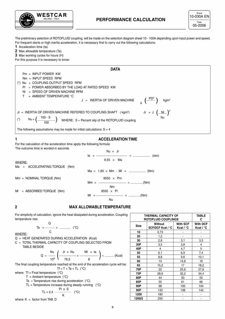
THERMAL CAPACITY OFROTOFLUID COUPLINGS
TABLEC
Size Without SCF/DCF Kcal / °C
With SCFKcal / °C
With DCFKcal / °C
10 0,73 - -20 1,2 - -30 2,8 3,1 3,3
30P 3,5 3,8 440P 4 4,7 550 6,1 6,9 7,455 8,8 9,6 10,160 13 14,8 1665 15,2 17 18,2
70P 22 25,6 27,875P 28,6 32,2 34,480P 44 50 5585P 55 61 6690P 98 100 10495P 133 138 1421200 180 - -
1200/2 250 - -
1 ACCELERATION TIMEFor the calculation of the acceleration time apply the following formula:The outcome time is worded in seconds
Nu × Jrta = __________________ = .................... (sec)
9,55 × MaWHERE:Ma = ACCELERATING TORQUE (Nm)
Ma = 1,65 × Mm - Ml = .................... (Nm)
Mm = NOMINAL TORQUE (Nm) 9550 × PmMm = ________________ = ...............(Nm)
NmMl = ABSORBED TORQUE (Nm) 9550 × Pl
Ml = ________________ = ..............(Nm)Nu
The preliminary selection of ROTOFLUID coupling, will be made on the selection diagram sheet 10 - 100A depending upon input power and speed. For frequent starts or high inertia acceleration, it is necessary first to carry out the following calculations:1 Acceleration time (ta)2 Max allowable temperature (Ta)3 Max working cycles for hours (H)For this purpose it is necessary to know:
DATAPm = INPUT POWER KWNm = INPUT SPEED RPM
(*) Nu = COUPLING OUTPUT SPEED RPMPl = POWER ABSORBED BY THE LOAD AT RATED SPEED KWNl = SPEED OF DRIVEN MACHINE RPMT = AMBIENT TEMPERATURE °C
PD2 J = INERTIA OF DRIVEN MACHINE (_____ ) kgm2
4
Jr = INERTIA OF DRIVEN MACHINE REFERED TO COUPLING SHAFT ( kgm2) Jr = J ( Nl )2
Nu 100 - S (*) Nu = (____________) WHERE: S = Percent slip of the ROTOFLUID coupling
100
The following assumations may be made for initial calculations: S = 4
2 MAX ALLOWABLE TEMPERATURE
For simplicity of calculation, ignore the heat dissipated during acceleration. Coupling temperature rise:
QTa = ______ = ............. (°C)
C WHERE:Q = HEAT GENERATED DURING ACCELERATION (Kcal)C = TOTAL THERMAL CAPACITY OF COUPLING SELECTED FROM TABLE BESIDE
Nu Jr × Nu Ml × taQ = ____ (__________ + ___________ ) = ........... (Kcal) 104 76,5 8
The final coupling temperature reached at the end of the acceleration cycle will be:Tf = T + Ta + TL (°C)
where: Tf = Final temperature (°C) T = Ambient temperature (°C) Ta = Temperature rise during acceleration (°C) TL = Temperature increase during steady running (°C)
Pl x STL = 2,4 ________________ (°C)
Kwhere: K = factor from TAB. D
MILANO - ITALYW
E
S T C A
R
MILANOITALY
Sheet
DatePERFORMANCE CALCULATION
10-031A EN
05-2006
9
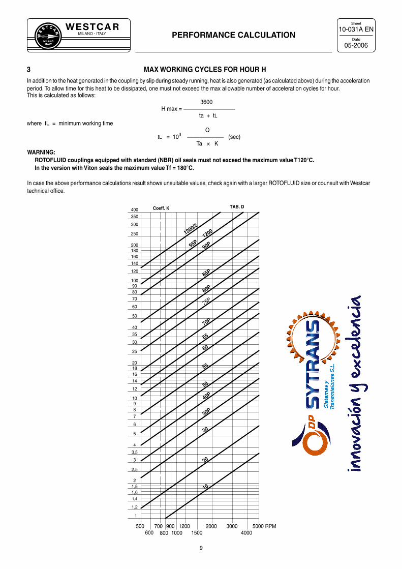
3 MAX WORKING CYCLES FOR HOUR HIn addition to the heat generated in the coupling by slip during steady running, heat is also generated (as calculated above) during the acceleration period. To allow time for this heat to be dissipated, one must not exceed the max allowable number of acceleration cycles for hour. This is calculated as follows:
3600 H max = _________________
ta + tLwhere tL = minimum working time
QtL = 103 ____________ (sec)
Ta × K
10
600
1
500
1,2
20001500800 1000
1200700 9004000
3000 RPM5000
3,5
1,61,4
21,8
2,5
3
6
4
5
87
9
80
16
12
14
2018
25
35
30
40
60
50
70
10090
120
160140
200180
350
250
300
400 Coeff. K TAB. D
20
10
30
30P
40P
50
55
60
65
70P
75P
80P
85P
90P95P12001200/2
WARNING: ROTOFLUID couplings equipped with standard (NBR) oil seals must not exceed the maximum value T120°C. In the version with Viton seals the maximum value Tf = 180°C.
In case the above performance calculations result shows unsuitable values, check again with a larger ROTOFLUID size or counsult with Westcar technical office.
MILANO - ITALYW
E
S T C A
R
MILANOITALY
Sheet
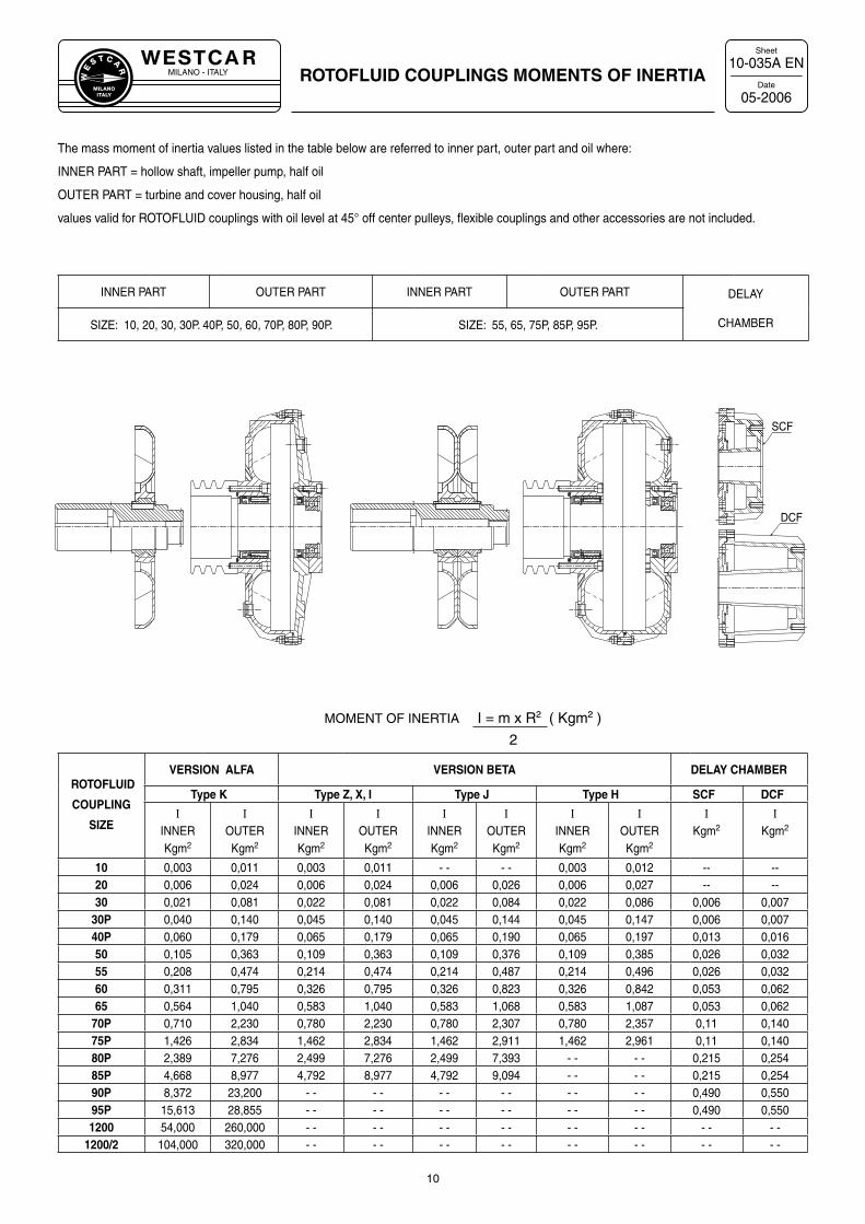
DateROTOFLUID COUPLINGS MOMENTS OF INERTIA
10-035A EN
05-2006
ROTOFLUID
COUPLING
SIZE
VERSION ALFA VERSION BETA DELAY CHAMBER
Type K Type Z, X, I Type J Type H SCF DCF
I
INNERKgm2
I
OUTERKgm2
I
INNERKgm2
I
OUTERKgm2
I
INNERKgm2
I
OUTERKgm2
I
INNERKgm2
I
OUTERKgm2
I
Kgm2
I
Kgm2
10 0,003 0,011 0,003 0,011 - - - - 0,003 0,012 -- --20 0,006 0,024 0,006 0,024 0,006 0,026 0,006 0,027 -- --30 0,021 0,081 0,022 0,081 0,022 0,084 0,022 0,086 0,006 0,007
30P 0,040 0,140 0,045 0,140 0,045 0,144 0,045 0,147 0,006 0,00740P 0,060 0,179 0,065 0,179 0,065 0,190 0,065 0,197 0,013 0,01650 0,105 0,363 0,109 0,363 0,109 0,376 0,109 0,385 0,026 0,03255 0,208 0,474 0,214 0,474 0,214 0,487 0,214 0,496 0,026 0,03260 0,311 0,795 0,326 0,795 0,326 0,823 0,326 0,842 0,053 0,06265 0,564 1,040 0,583 1,040 0,583 1,068 0,583 1,087 0,053 0,062
70P 0,710 2,230 0,780 2,230 0,780 2,307 0,780 2,357 0,11 0,14075P 1,426 2,834 1,462 2,834 1,462 2,911 1,462 2,961 0,11 0,14080P 2,389 7,276 2,499 7,276 2,499 7,393 - - - - 0,215 0,25485P 4,668 8,977 4,792 8,977 4,792 9,094 - - - - 0,215 0,25490P 8,372 23,200 - - - - - - - - - - - - 0,490 0,55095P 15,613 28,855 - - - - - - - - - - - - 0,490 0,5501200 54,000 260,000 - - - - - - - - - - - - - - - -
1200/2 104,000 320,000 - - - - - - - - - - - - - - - -
The mass moment of inertia values listed in the table below are referred to inner part, outer part and oil where:
INNER PART = hollow shaft, impeller pump, half oil
OUTER PART = turbine and cover housing, half oil
values valid for ROTOFLUID couplings with oil level at 45° off center pulleys, flexible couplings and other accessories are not included.
INNER PART OUTER PART INNER PART OUTER PART DELAY
CHAMBERSIZE: 10, 20, 30, 30P. 40P, 50, 60, 70P, 80P, 90P. SIZE: 55, 65, 75P, 85P, 95P.
10
MOMENT OF INERTIA I = m x R² ( Kgm² )
2
SCF
DCF
MILANO - ITALYW
E
S T C A
R
MILANOITALY
Sheet
Date
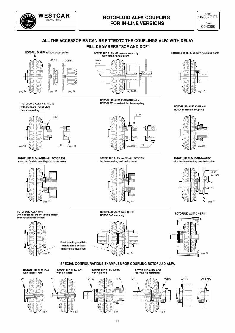
ROTOFLUID ALFA COUPLING FOR IN-LINE VERSIONS
10-057B EN
05-2006
ALL THE ACCESSORIES CAN BE FITTED TO THE COUPLINGS ALFA WITH DELAY FILL CHAMBERS “SCF AND DCF”
11
FRVLRV
LRU FRU
KSCF K DCF K
ROTOFLUID ALFA K-FRV/FRU with
ROTOFLUID ALFA KK reverse assemblywith disc or brake drum
ROTOFLUID ALFA without accessories
ROTOFLUID ALFA K-AB withROTOPIN flexible coupling
ROTOFLUID ALFA KS with rigid stub shaft
ROTOFLUID ALFA K-LRV/LRU with standard ROTOFLEXIflexible coupling
ROTOFLEXI oversized flexible coupling
Motorside
ROTOFLUID ALFA WAG-G with ROTOGEAR coupling
ROTOFLUID ALFA WAGwith flanges for the mounting of halfgear couplings in inches
Brakedisc PAV
ROTOFLUID ALFA CK-LRS
ROTOFLUID ALFA K-AFF with ROTOPINflexible coupling and brake drum
ROTOFLUID ALFA K-FRD with ROTOFLEXI oversized flexible coupling and brake drum
ROTOFLUID ALFA K-FR-PAV/PBVwith flexible coupling and brake disc
Fluid couplings radially demountable without moving the machines
pag. 14 pag. 15 pag. 16 pag. 26/27 pag. 17
pag. 18 pag. 19 pag. 20/21 pag. 22
pag. 23 pag. 24 pag. 25
pag. 30 pag. 31 pag. 32
ROTOFLUID ALFA K-Wwith flange shaft
ROTOFLUID ALFA K-Ywith pin shaft
ROTOFLUID ALFA K-VFWwith rigid hub
ROTOFLUID ALFA K-VFfor "reverse mounting"
W Y VF WRV WRD WRPAVFRVVFW
Fig. 1 Fig. 2 Fig. 3 Fig. 4
SPECIAL CONFIGURATIONS EXAMPLES FOR COUPLING ROTOFLUID ALFA
MILANO - ITALYW
E
S T C A
R
MILANOITALY
Sheet
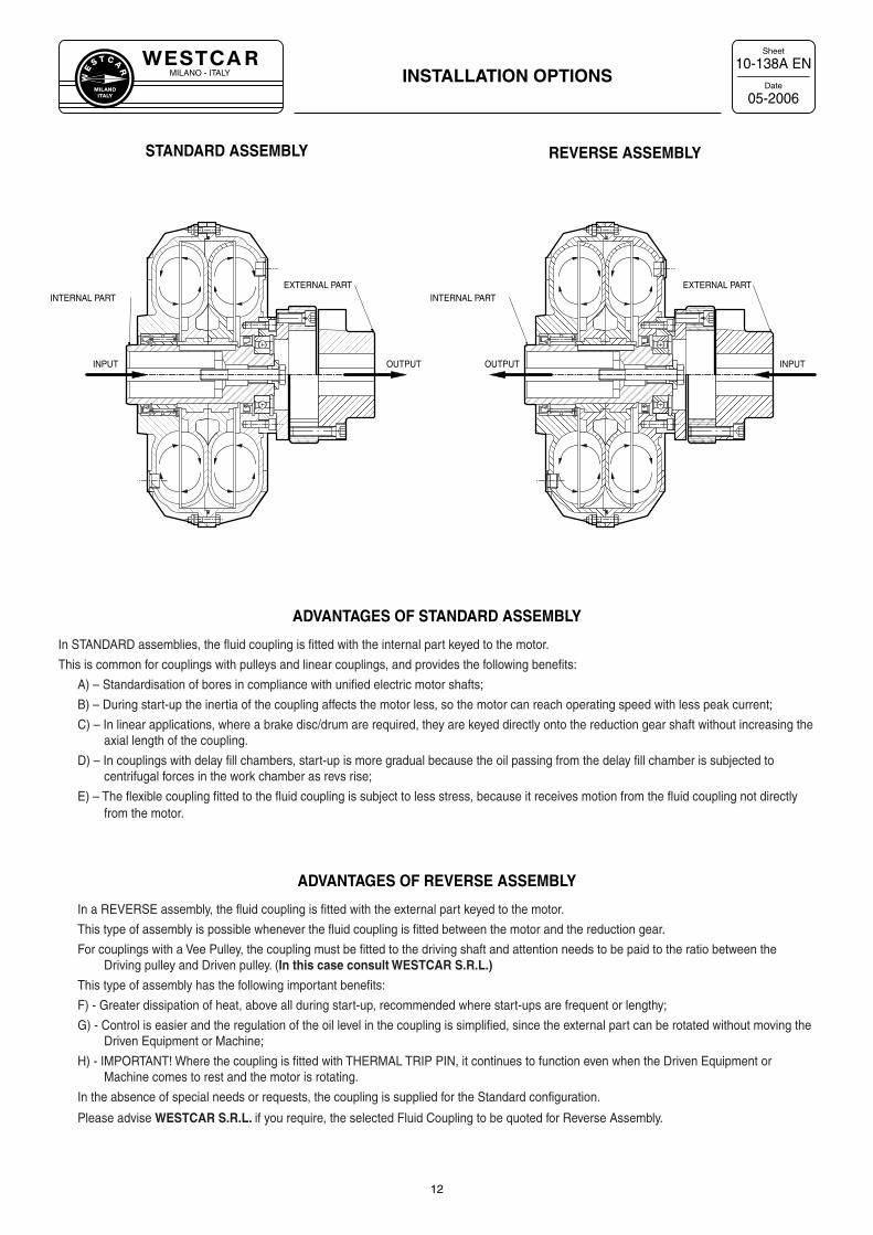
DateINSTALLATION OPTIONS
10-138A EN
05-2006
12
ADVANTAGES OF STANDARD ASSEMBLY
In STANDARD assemblies, the fluid coupling is fitted with the internal part keyed to the motor.
This is common for couplings with pulleys and linear couplings, and provides the following benefits:
A) – Standardisation of bores in compliance with unified electric motor shafts;
B) – During start-up the inertia of the coupling affects the motor less, so the motor can reach operating speed with less peak current;
C) – In linear applications, where a brake disc/drum are required, they are keyed directly onto the reduction gear shaft without increasing the axial length of the coupling.
D) – In couplings with delay fill chambers, start-up is more gradual because the oil passing from the delay fill chamber is subjected to centrifugal forces in the work chamber as revs rise;
E) – The flexible coupling fitted to the fluid coupling is subject to less stress, because it receives motion from the fluid coupling not directly from the motor.
ADVANTAGES OF REVERSE ASSEMBLY
In a REVERSE assembly, the fluid coupling is fitted with the external part keyed to the motor.
This type of assembly is possible whenever the fluid coupling is fitted between the motor and the reduction gear.
For couplings with a Vee Pulley, the coupling must be fitted to the driving shaft and attention needs to be paid to the ratio between the Driving pulley and Driven pulley. (In this case consult WESTCAR S.R.L.)
This type of assembly has the following important benefits:
F) - Greater dissipation of heat, above all during start-up, recommended where start-ups are frequent or lengthy;
G) - Control is easier and the regulation of the oil level in the coupling is simplified, since the external part can be rotated without moving theDriven Equipment or Machine;
H) - IMPORTANT! Where the coupling is fitted with THERMAL TRIP PIN, it continues to function even when the Driven Equipment orMachine comes to rest and the motor is rotating.
In the absence of special needs or requests, the coupling is supplied for the Standard configuration.
Please advise WESTCAR S.R.L. if you require, the selected Fluid Coupling to be quoted for Reverse Assembly.
REVERSE ASSEMBLYSTANDARD ASSEMBLY
INPUT
INTERNAL PART
OUTPUT
EXTERNAL PARTINTERNAL PART
INPUT
EXTERNAL PART
OUTPUT
MILANO - ITALYW
E
S T C A
R
MILANOITALY
Sheet
Date
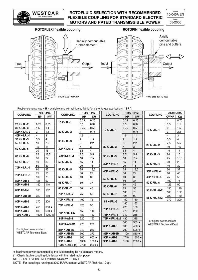
Rubber elements type « R » available also with reinforced fabric for higher torque applications’ “ BR ”.
COUPLING750 R.P.M.
COUPLING1000 R.P.M.
COUPLING1500 R.P.M.
COUPLING3000 R.P.M.
HP KW HP KW HP KW CV/HP KW
10 K-LR..-10,33 0,25
10 K-LR..-1
0,33 0,25
10 K-LR..-1
1 0,7520 K-LR..-2 0,75 0,55 0,5 0,37 0,5 0,37 1,5 1,130 K-LR..-3 1,5 1,1
20 K-LR..-20,75 0,55 0,75 0,55 2 1,5
30P K-LR..-3 2 1,5 1 0,75 1 0,75 3 2,240P K-LR..-4 4 3 1,5 1,1 1,5 1,1 4 350 K-LR..-5 5,5 4
30 K-LR..-32 1,5 2 1,5 5,5 4
55 K-LR..-5 10 7,5 3 2,220 K-LR..-2
3 2,220 K-LR..-2
7,5 5,5
60 K-LR..-615 11
30P K-LR..-34 3 4 3 10 7,5
20 15 5,5 4 5,5 430 K-LR..-3
15 11
65 K-LR..-625 18,5
40P K-LR..-47,5 5,5
30 K-LR..-37,5 5,5 20 15
30 22 10 7,5 10 7,5 25 18,565 K-FR..-7 40 30 50 K-LR..-5 15 11
30P K-FR..-415 11
30 K-FR..-430 22
70P K-LR..-750 37
55 K-LR..-520 15 20 15 40 30
60 45 25 18,540P K-FR..-5
25 18,530P K-FR..-4
50 37
75P K-FR..-875 55 30 22 30 22 60 45100 75 60 K-LR..-6 40 30
50 K-FR..-640 30 40P K-FR..-5 75 55
80P K-AB-8 125 9065 K-FR..-7 50 37
50 3750 K-FR..-6
100 7580P K-AB-8 150 110
55 K-FR..-660 45 125 90
85P AB-8M 180 13265 K-FR..-7 60 45 75 55
50 K-FR..-6x2150 110
70P K-LR..-7 75 55 60 K-FR..-7100 75 180 132
85P K-AB-8M 220 160 125 9055 K-FR..-6x2
220 160
90P K-AB-9 270 20070P K-FR..-8 100 75
65 K-FR..-7150 110 270 200
75P K-FR..-8 125 90180 132
For higher power contact WESTCAR Technical Dept.
90P K-AB-9 450 330 ★70P K-FR..-8
220 16095P K-AB-9 800 600 ★
75P KFR..-8x2150 110 270 200
1200 K-AB-9 1600 1200 ★ 180 132 75P K-FR..-8 340 255
For higher power contact WESTCAR Technical Dept.
80P K-AB-8 220 160 75P K-FR..-8x2 430 315
85P K-AB-8M 270 20080P K-AB-8
500 365 ★600 450 ★
85P K-AB-8M 340 250 700 525 ★85P K-AB-8M 500 370 85P K-AB-8M 1100 810 ★90P K-AB-9 800 600 ★ 90P K-AB-9 1740 1300 ★95P K-AB-9 1360 1000 ★ 95P K-AB-9 3100 2300 ★1200 K-AB-9 (1) 2720 2000 ★
★ Maximum power transmitted by the fluid coupling for no standard motors. (1) Check flexible coupling duty factor with the rated motor power NOTE - For REVERSE MOUNTING advise WESTCARNOTE - For couplings running at 3000 R.P.M. contact WESTCAR Technical Dept.
ROTOFLUID SELECTION WITH RECOMMENDEDFLEXIBLE COUPLING FOR STANDARD ELECTRICMOTORS AND RATED TRANSMISSIBLE POWER
10-040A EN
05-2006
13
Input Output Output Input
Radially demountable rubber element
Axially demountable pins and buffers
FROM SIZE 10 TO 75P FROM SIZE 80P TO 1200
ROTOFLEXI flexible coupling ROTOPIN flexible coupling
MILANO - ITALYW
E
S T C A
R
MILANOITALY
Sheet
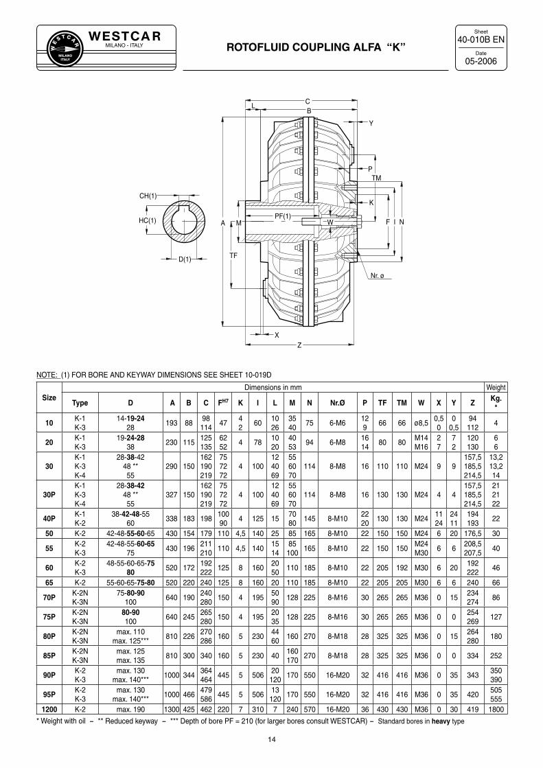
DateROTOFLUID COUPLING ALFA “K”
40-010B EN
05-2006
14
PF(1)
Z
A
TF
L
D(1)
CH(1)
HC(1) M
TM
B
F NI
K
P
X
Nr. ø
Y
C
W
NOTE: (1) FOR BORE AND KEYWAY DIMENSIONS SEE SHEET 10-019D
SizeDimensions in mm Weight
Type D A B C FH7 K I L M N Nr.Ø P TF TM W X Y ZKg.
*
10 K-1K-3
14-19-2428
193 8898114
4742
601026
3540
75 6-M6129
66 66 ø8,50,50
00,5
94112
4
20 K-1K-3
19-24-2838
230 115125135
6252
4 781020
4053
94 6-M81614
80 80M14M16
27
72
120130
66
30K-1K-3K-4
28-38-4248 **55
290 150162190219
757272
4 100124069
556070
114 8-M8 16 110 110 M24 9 9157,5185,5214,5
13,213,214
30PK-1K-3K-4
28-38-4248 **55
327 150162190219
757272
4 100124069
556070
114 8-M8 16 130 130 M24 4 4157,5185,5214,5
212122
40P K-1K-2
38-42-48-5560
338 183 19810090
4 125 157080
145 8-M102220
130 130 M241124
2411
194193
22
50 K-2 42-48-55-60-65 430 154 179 110 4,5 140 25 85 165 8-M10 22 150 150 M24 6 20 176,5 30
55 K-2K-3
42-48-55-60-6575
430 196211210
110 4,5 1401514
85100
165 8-M10 22 150 150M24M30
6 6208,5207,5
40
60 K-2K-3
48-55-60-65-7580 520 172
192222
125 8 1602050
110 185 8-M10 22 205 192 M30 6 20192222
46
65 K-2 55-60-65-75-80 520 220 240 125 8 160 20 110 185 8-M10 22 205 205 M30 6 6 240 66
70P K-2NK-3N
75-80-90100
640 190240280
150 4 1955090
128 225 8-M16 30 265 265 M36 0 15234274
86
75P K-2NK-3N
80-90100
640 245265280
150 4 1952035
128 225 8-M16 30 265 265 M36 0 0254269
127
80P K-2NK-3N
max. 110max. 125***
810 226270286
160 5 2304460
160 270 8-M18 28 325 325 M36 0 15264280
180
85P K-2NK-3N
max. 125max. 135
810 300 340 160 5 230 40160170
270 8-M18 28 325 325 M36 0 0 334 252
90P K-2K-3
max. 130max. 140***
1000 344364464
445 5 50620
120170 550 16-M20 32 416 416 M36 0 35 343
350390
95P K-2K-3
max. 130max. 140***
1000 466479586
445 5 50613
120170 550 16-M20 32 416 416 M36 0 35 420
505555
1200 K-2 max. 190 1300 425 462 220 7 310 7 240 570 16-M20 36 430 430 M36 0 30 419 1800
* Weight with oil - ** Reduced keyway - *** Depth of bore PF = 210 (for larger bores consult WESTCAR) - Standard bores in heavy type
MILANO - ITALYW
E
S T C A
R
MILANOITALY
Sheet
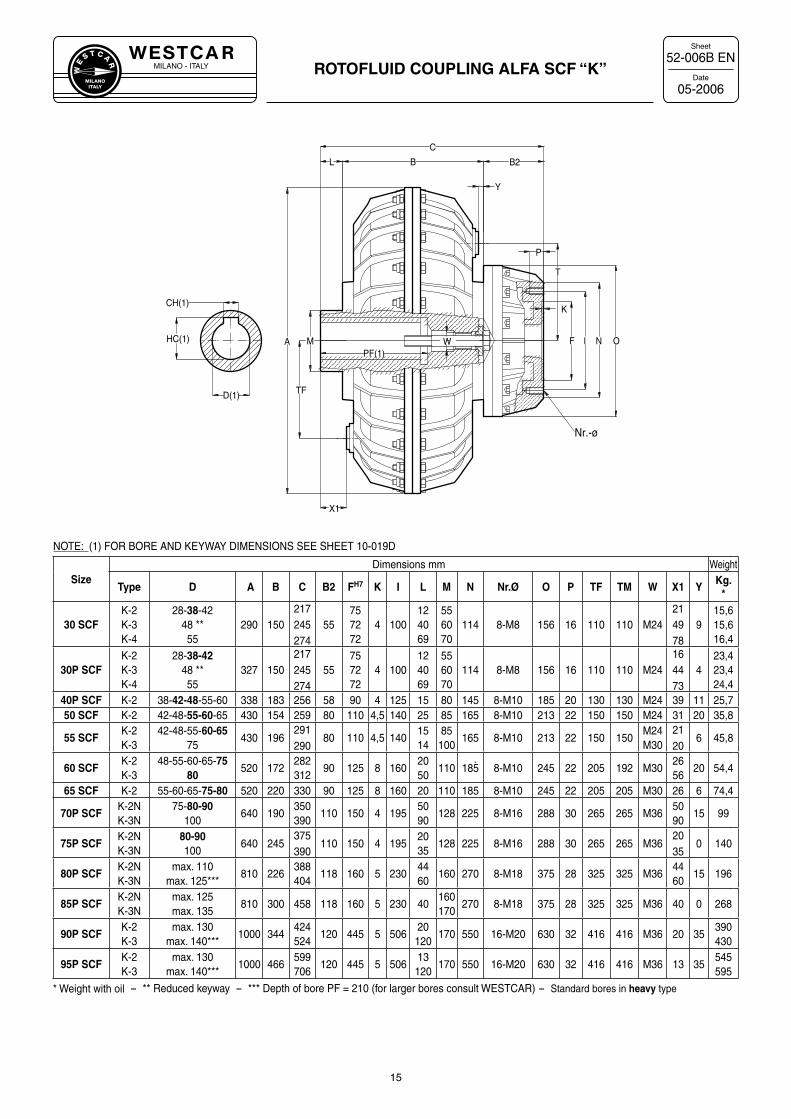
DateROTOFLUID COUPLING ALFA SCF “K”
52-006B EN
05-2006
15
A
TF
HC(1)
CH(1)
D(1)
BL
PF(1)M NIF
T
P
K
B2
X1
Nr.-ø
Y
C
OW
NOTE: (1) FOR BORE AND KEYWAY DIMENSIONS SEE SHEET 10-019D
SizeDimensions mm Weight
Type D A B C B2 FH7 K I L M N Nr.Ø O P TF TM W X1 YKg.
*
30 SCFK-2K-3K-4
28-38-4248 **55
290 150217245274
55757272
4 100124069
556070
114 8-M8 156 16 110 110 M24214978
915,615,616,4
30P SCFK-2K-3K-4
28-38-4248 **55
327 150217245274
55757272
4 100124069
556070
114 8-M8 156 16 110 110 M24164473
423,423,424,4
40P SCF K-2 38-42-48-55-60 338 183 256 58 90 4 125 15 80 145 8-M10 185 20 130 130 M24 39 11 25,750 SCF K-2 42-48-55-60-65 430 154 259 80 110 4,5 140 25 85 165 8-M10 213 22 150 150 M24 31 20 35,8
55 SCFK-2K-3
42-48-55-60-6575
430 196291290
80 110 4,5 1401514
85100
165 8-M10 213 22 150 150M24M30
2120
6 45,8
60 SCFK-2K-3
48-55-60-65-7580
520 172282312
90 125 8 1602050
110 185 8-M10 245 22 205 192 M302656
20 54,4
65 SCF K-2 55-60-65-75-80 520 220 330 90 125 8 160 20 110 185 8-M10 245 22 205 205 M30 26 6 74,4
70P SCFK-2NK-3N
75-80-90100
640 190350390
110 150 4 1955090
128 225 8-M16 288 30 265 265 M365090
15 99
75P SCFK-2NK-3N
80-90100
640 245375390
110 150 4 1952035
128 225 8-M16 288 30 265 265 M362035
0 140
80P SCFK-2NK-3N
max. 110max. 125***
810 226388404
118 160 5 2304460
160 270 8-M18 375 28 325 325 M364460
15 196
85P SCFK-2NK-3N
max. 125max. 135
810 300 458 118 160 5 230 40160170
270 8-M18 375 28 325 325 M36 40 0 268
90P SCFK-2K-3
max. 130max. 140***
1000 344424524
120 445 5 50620
120170 550 16-M20 630 32 416 416 M36 20 35
390430
95P SCFK-2K-3
max. 130max. 140***
1000 466599706
120 445 5 50613
120170 550 16-M20 630 32 416 416 M36 13 35
545595
* Weight with oil - ** Reduced keyway - *** Depth of bore PF = 210 (for larger bores consult WESTCAR) - Standard bores in heavy type
MILANO - ITALYW
E
S T C A
R
MILANOITALY
Sheet
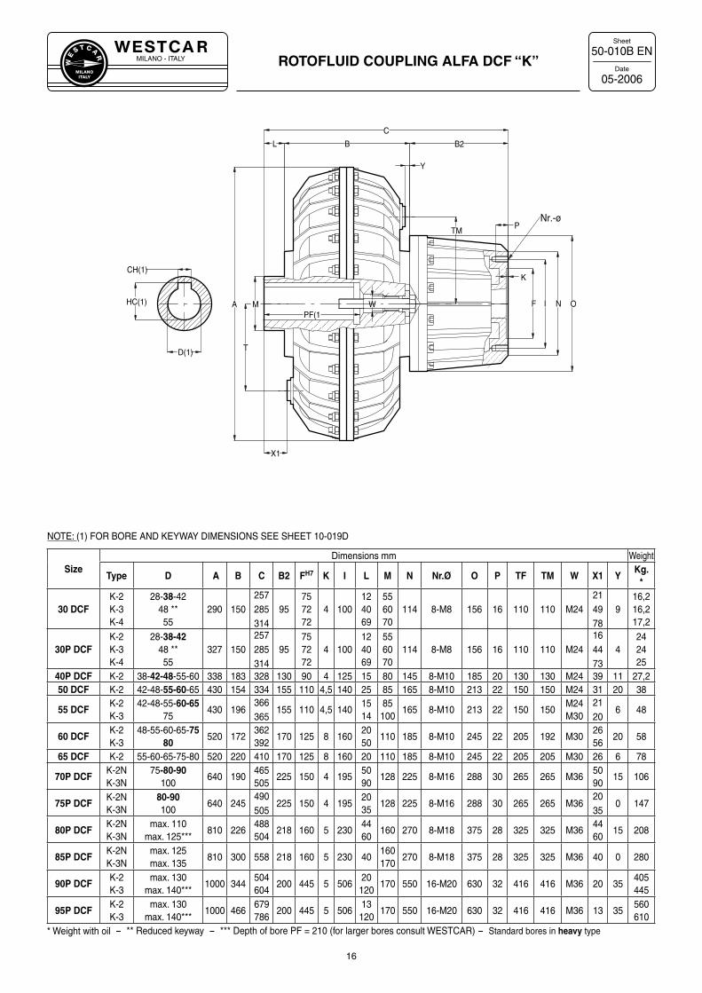
DateROTOFLUID COUPLING ALFA DCF “K”
50-010B EN
05-2006
16
A
T
HC(1)
CH(1)
D(1)
BL
PF(1M NIF
TMP
K
W
B2
X1
Nr.-ø
Y
C
O
NOTE: (1) FOR BORE AND KEYWAY DIMENSIONS SEE SHEET 10-019D
SizeDimensions mm Weight
Type D A B C B2 FH7 K I L M N Nr.Ø O P TF TM W X1 YKg.
*
30 DCFK-2K-3K-4
28-38-4248 **55
290 150257285314
95757272
4 100124069
556070
114 8-M8 156 16 110 110 M24214978
916,216,217,2
30P DCFK-2K-3K-4
28-38-4248 **55
327 150257285314
95757272
4 100124069
556070
114 8-M8 156 16 110 110 M24164473
4242425
40P DCF K-2 38-42-48-55-60 338 183 328 130 90 4 125 15 80 145 8-M10 185 20 130 130 M24 39 11 27,250 DCF K-2 42-48-55-60-65 430 154 334 155 110 4,5 140 25 85 165 8-M10 213 22 150 150 M24 31 20 38
55 DCFK-2K-3
42-48-55-60-6575
430 196366365
155 110 4,5 1401514
85100
165 8-M10 213 22 150 150M24M30
2120
6 48
60 DCFK-2K-3
48-55-60-65-7580
520 172362392
170 125 8 1602050
110 185 8-M10 245 22 205 192 M302656
20 58
65 DCF K-2 55-60-65-75-80 520 220 410 170 125 8 160 20 110 185 8-M10 245 22 205 205 M30 26 6 78
70P DCFK-2NK-3N
75-80-90100
640 190465505
225 150 4 1955090
128 225 8-M16 288 30 265 265 M365090
15 106
75P DCFK-2NK-3N
80-90100
640 245490505
225 150 4 1952035
128 225 8-M16 288 30 265 265 M362035
0 147
80P DCFK-2NK-3N
max. 110max. 125***
810 226488504
218 160 5 2304460
160 270 8-M18 375 28 325 325 M364460
15 208
85P DCFK-2NK-3N
max. 125max. 135
810 300 558 218 160 5 230 40160170
270 8-M18 375 28 325 325 M36 40 0 280
90P DCFK-2K-3
max. 130max. 140***
1000 344504604
200 445 5 50620
120170 550 16-M20 630 32 416 416 M36 20 35
405445
95P DCFK-2K-3
max. 130max. 140***
1000 466679786
200 445 5 50613
120170 550 16-M20 630 32 416 416 M36 13 35
560610
* Weight with oil - ** Reduced keyway - *** Depth of bore PF = 210 (for larger bores consult WESTCAR) - Standard bores in heavy type
MILANO - ITALYW
E
S T C A
R
MILANOITALY
Sheet
Date
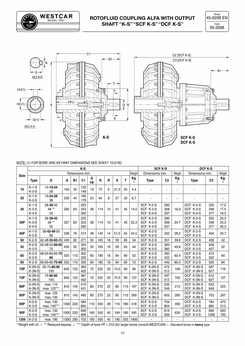
ROTOFLUID COUPLING ALFA WITH OUTPUT SHAFT “K-S” “SCF K-S” “DCF K-S”
45-020B EN
05-2006
17
C2 [SCF K-S]
B1
C3 [DCF K-S]
SCF K-SDCF K-S
B
B
A
A
PF(1A
D(1)
CH(1)
HC(1) G N
T
S
R
SEZ.A-A
SEZ.B-B
B1
C1
K-S
NOTE: (1) FOR BORE AND KEYWAY DIMENSIONS SEE SHEET 10-019D
Size
K-S SCF K-S DCF K-SDimensions mm. Weight Dimensions mm. Weight Dimensions mm. Weight
Type D A B1 C1Gh6
N R S TKg.
*Type C2
Kg.*
Type C3Kg.
*
10 K-1-SK-3-S
14-19-2428
193 35133149
19 75 6 21,5 25 4,4 - - - - - -
20 K-1-SK-3-S
19-24-2838
230 44169179
24 94 8 27 32 6,7 - - - - - -
30K-1-SK-3-SK-4-S
28-38-4248 **55
290 63225253282
38 114 10 41 45 14,5SCF K-2-SSCF K-3-SSCF K-4-S
280308337
16,9DCF K-2-SDCF K-3-SDCF K-4-S
320348377
17,517,518,5
30PK-1-SK-3-SK-4-S
28-38-4248 **55
327 63225253282
38 114 10 41 45 22,3SCF K-2-SSCF K-3-SSCF K-4-S
280308337
24,7DCF K-2-SDCF K-3-SDCF K-4-S
320348377
25,325,326,3
40P K-1-SK-2-S
38-42-48-5560
338 76 274 48 145 14 51,5 55 24,5SCF K-2-SSCF K-2-S
332 28,2DCF K-2-SDCF K-2-S
404 29,7
50 K-2-S 42-48-55-60-65 430 92 271 55 165 16 59 65 34 SCF K-2-S 351 39,8 DCF K-2-S 426 42
55 K-2-SK-3-S
42-48-55-60-6575
430 92303302
55 165 16 59 65 44SCF K-2-SSCF K-3-S
383382
49,8DCF K-2-SDCF K-3-S
458457
52
60 K-2-SK-3-S
48-55-60-65-7580 520 110
302332
60 185 18 64 80 52SCF K-2-SSCF K-3-S
392422
60,4DCF K-2-SDCF K-3-S
472502
64
65 K-2-S 55-60-65-75-80 520 110 350 60 185 18 64 80 72 SCF K-2-S 440 80,4 DCF K-2-S 520 84
70P K-2N-SK-3N-S
65-75-80-90100
640 122362402
70 225 20 74,5 90 96SCF K-2N-SSCF K-3N-S
472512
109DCF K-2N-SDCF K-3N-S
587627
116
75P K-2N-SK-3N-S
75-80-90100
640 122387402
70 225 20 74,5 90 137SCF K-2N-SSCF K-3N-S
497512
150DCF K-2N-SDCF K-3N-S
612627
157
80P K-2N-SK-3N-S
max. 110max. 125***
810 145415431
80 270 22 85 110 197SCF K-2N-SSCF K-3N-S
533549
213DCF K-2N-SDCF K-3N-S
633649
225
85P K-2N-SK-3N-S
max. 125max. 135
810 145 485 80 270 22 85 110 269SCF K-2N-SSCF K-3N-S
603 285DCF K-2N-SDCF K-3N-S
703 297
90P K-2-SK-3-S
max. 130max. 140***
1000 220584684
110 550 28 116 180 418SCF K-2-SSCF K-3-S
704804
458DCF K-2-SDCF K-3-S
784884
473513
95P K-2-SK-3-S
max. 130max. 140***
1000 220699806
160 550 40 169 180 595SCF K-2-SSCF K-3-S
819926
635DCF K-2-SDCF K-3-S
8991006
650700
1200 K-2-S max. 190 1300 290 752 180 550 45 190 250 1900 - - - - - -
* Weight with oil - ** Reduced keyway - *** Depth of bore PF = 210 (for larger bores consult WESTCAR) - Standard bores in heavy type
MILANO - ITALYW
E
S T C A
R
MILANOITALY
Sheet
Date
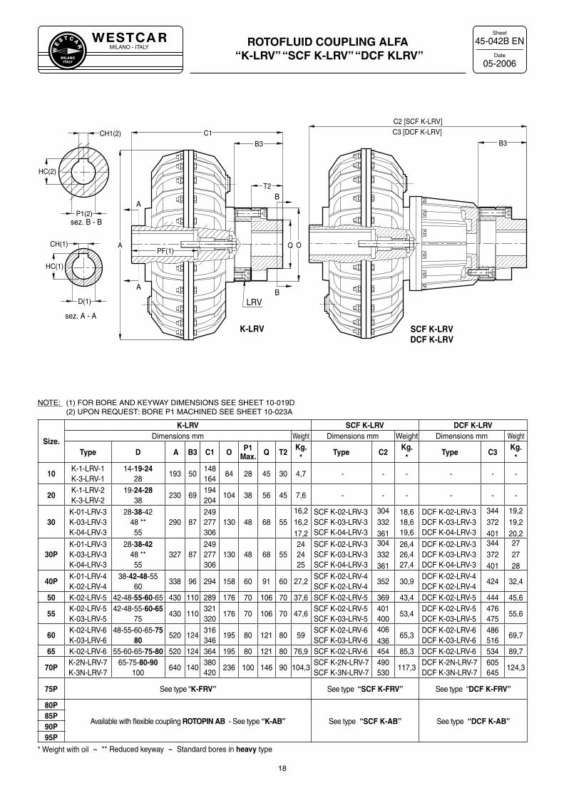
ROTOFLUID COUPLING ALFA “K-LRV” “SCF K-LRV” “DCF KLRV”
45-042B EN
05-2006
18
sez. A - A
sez. B - B
AB
BA
D(1)
CH(1) A O
T2
B3
PF(1)Q
P1(2)
CH1(2)
HC(1)
B3C1
C2 [SCF K-LRV]
LRV
HC(2)
K-LRV SCF K-LRVDCF K-LRV
C3 [DCF K-LRV]
Size.
K-LRV SCF K-LRV DCF K-LRVDimensions mm Weight Dimensions mm Weight Dimensions mm Weight
Type D A B3 C1 O P1Max. Q T2
Kg.*
Type C2Kg.
*Type C3
Kg.*
10K-1-LRV-1K-3-LRV-1
14-19-2428
193 50148164
84 28 45 30 4,7 - - - - - -
20K-1-LRV-2K-3-LRV-2
19-24-2838
230 69194204
104 38 56 45 7,6 - - - - - -
30K-01-LRV-3K-03-LRV-3K-04-LRV-3
28-38-4248 **55
290 87249277306
130 48 68 5516,216,217,2
SCF K-02-LRV-3SCF K-03-LRV-3SCF K-04-LRV-3
304332361
18,618,619,6
DCF K-02-LRV-3DCF K-03-LRV-3DCF K-04-LRV-3
344372401
19,219,220,2
30PK-01-LRV-3K-03-LRV-3K-04-LRV-3
28-38-4248 **55
327 87249277306
130 48 68 55242425
SCF K-02-LRV-3SCF K-03-LRV-3SCF K-04-LRV-3
304332361
26,426,427,4
DCF K-02-LRV-3DCF K-03-LRV-3DCF K-04-LRV-3
344372401
272728
40PK-01-LRV-4K-02-LRV-4
38-42-48-5560
338 96 294 158 60 91 60 27,2SCF K-02-LRV-4SCF K-02-LRV-4
352 30,9DCF K-02-LRV-4DCF K-02-LRV-4
424 32,4
50 K-02-LRV-5 42-48-55-60-65 430 110 289 176 70 106 70 37,6 SCF K-02-LRV-5 369 43,4 DCF K-02-LRV-5 444 45,6
55K-02-LRV-5K-03-LRV-5
42-48-55-60-6575
430 110321320
176 70 106 70 47,6SCF K-02-LRV-5SCF K-03-LRV-5
401400
53,4DCF K-02-LRV-5DCF K-03-LRV-5
476475
55,6
60K-02-LRV-6K-03-LRV-6
48-55-60-65-7580
520 124316346
195 80 121 80 59SCF K-02-LRV-6SCF K-03-LRV-6
406436
65,3DCF K-02-LRV-6DCF K-03-LRV-6
486516
69,7
65 K-02-LRV-6 55-60-65-75-80 520 124 364 195 80 121 80 76,9 SCF K-02-LRV-6 454 85,3 DCF K-02-LRV-6 534 89,7
70PK-2N-LRV-7K-3N-LRV-7
65-75-80-90100
640 140380420
236 100 146 90 104,3SCF K-2N-LRV-7SCF K-3N-LRV-7
490530
117,3DCF K-2N-LRV-7DCF K-3N-LRV-7
605645
124,3
75P See type “K-FRV” See type “SCF K-FRV” See type “DCF K-FRV”
80P
Available with flexible coupling ROTOPIN AB - See type “K-AB” See type “SCF K-AB” See type “DCF K-AB”85P90P95P
* Weight with oil - ** Reduced keyway - Standard bores in heavy type
NOTE: (1) FOR BORE AND KEYWAY DIMENSIONS SEE SHEET 10-019D(2) UPON REQUEST: BORE P1 MACHINED SEE SHEET 10-023A
MILANO - ITALYW
E
S T C A
R
MILANOITALY
Sheet
Date
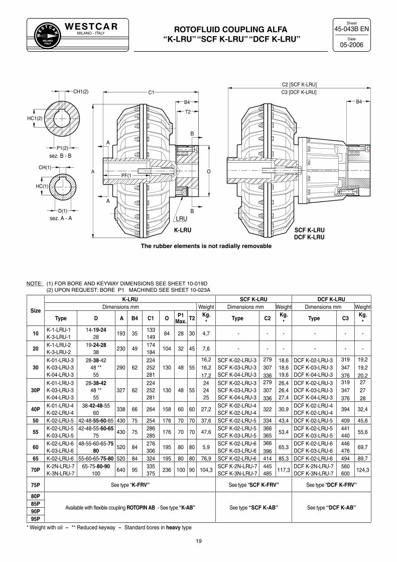
ROTOFLUID COUPLING ALFA “K-LRU” “SCF K-LRU” “DCF K-LRU”
45-043B EN
05-2006
19
sez. A - A
sez. B - B
A
B
B
A
D(1)
CH(1)A
PF(1
P1(2)
CH1(2)
HC(1)
O
T2HC1(2)
C1
LRU
B4 B4
K-LRU SCF K-LRUDCF K-LRU
Size
K-LRU SCF K-LRU DCF K-LRUDimensions mm Weight Dimensions mm Weight Dimensions mm Weight
Type D A B4 C1 O P1Max. T2
Kg.*
Type C2Kg.
*Type C3
Kg.*
10K-1-LRU-1K-3-LRU-1
14-19-2428
193 35133149
84 28 30 4,7 - - - - - -
20K-1-LRU-2K-3-LRU-2
19-24-2838
230 49174184
104 32 45 7,6 - - - - - -
30K-01-LRU-3K-03-LRU-3K-04-LRU-3
28-38-4248 **55
290 62224252281
130 48 5516,216,217,2
SCF K-02-LRU-3SCF K-03-LRU-3SCF K-04-LRU-3
279307336
18,618,619,6
DCF K-02-LRU-3DCF K-03-LRU-3DCF K-04-LRU-3
319347376
19,219,220,2
30PK-01-LRU-3K-03-LRU-3K-04-LRU-3
28-38-4248 **55
327 62224252281
130 48 55242425
SCF K-02-LRU-3SCF K-03-LRU-3SCF K-04-LRU-3
279307336
26,426,427,4
DCF K-02-LRU-3DCF K-03-LRU-3DCF K-04-LRU-3
319347376
272728
40PK-01-LRU-4K-02-LRU-4
38-42-48-5560
338 66 264 158 60 60 27,2SCF K-02-LRU-4SCF K-02-LRU-4
322 30,9DCF K-02-LRU-4DCF K-02-LRU-4
394 32,4
50 K-02-LRU-5 42-48-55-60-65 430 75 254 176 70 70 37,6 SCF K-02-LRU-5 334 43,4 DCF K-02-LRU-5 409 45,6
55K-02-LRU-5K-03-LRU-5
42-48-55-60-6575
430 75286285
176 70 70 47,6SCF K-02-LRU-5SCF K-03-LRU-5
366365
53,4DCF K-02-LRU-5DCF K-03-LRU-5
441440
55,6
60K-02-LRU-6K-03-LRU-6
48-55-60-65-7580
520 84276306
195 80 80 5,9SCF K-02-LRU-6SCF K-03-LRU-6
366396
65,3DCF K-02-LRU-6DCF K-03-LRU-6
446476
69,7
65 K-02-LRU-6 55-60-65-75-80 520 84 324 195 80 80 76,9 SCF K-02-LRU-6 414 85,3 DCF K-02-LRU-6 494 89,7
70PK-2N-LRU-7K-3N-LRU-7
65-75-80-90100
640 95335375
236 100 90 104,3SCF K-2N-LRU-7SCF K-3N-LRU-7
445485
117,3DCF K-2N-LRU-7DCF K-3N-LRU-7
560600
124,3
75P See type “K-FRV” See type “SCF K-FRV” See type “DCF K-FRV”
80P
Available with flexible coupling ROTOPIN AB - See type “K-AB” See type “SCF K-AB” See type “DCF K-AB”85P90P95P
* Weight with oil - ** Reduced keyway - Standard bores in heavy type
The rubber elements is not radially removable
NOTE: (1) FOR BORE AND KEYWAY DIMENSIONS SEE SHEET 10-019D (2) UPON REQUEST: BORE P1 MACHINED SEE SHEET 10-023A
MILANO - ITALYW
E
S T C A
R
MILANOITALY
Sheet
Date
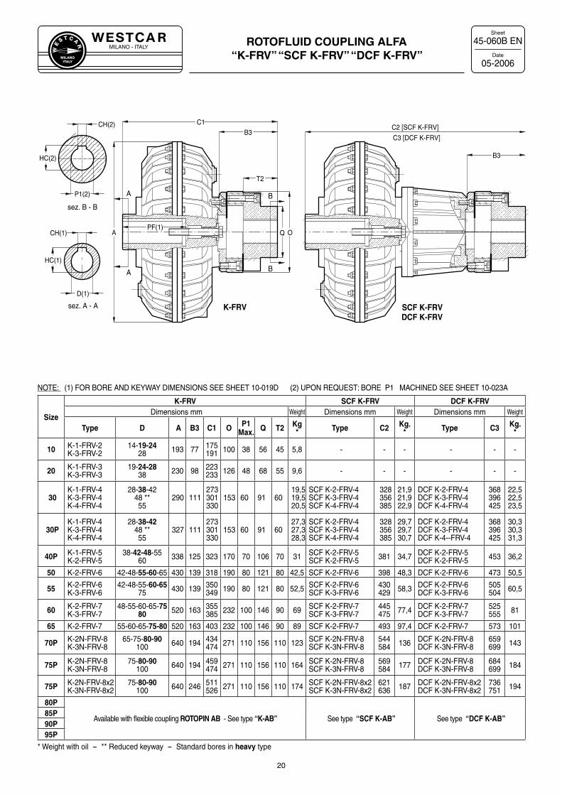
ROTOFLUID COUPLING ALFA “K-FRV” “SCF K-FRV” “DCF K-FRV”
45-060B EN
05-2006
20
A
A B
B
APF(1)
O
T2
B3
P1(2)
B3
Q
C1C2 [SCF K-FRV]CH(2)
sez. B - B
sez. A - A
D(1)
CH(1)
HC(1)
HC(2)
C3 [DCF K-FRV]
K-FRV SCF K-FRVDCF K-FRV
Size
K-FRV SCF K-FRV DCF K-FRVDimensions mm Weight Dimensions mm Weight Dimensions mm Weight
Type D A B3 C1 O P1Max. Q T2 Kg
* Type C2 Kg.* Type C3 Kg.
*
10 K-1-FRV-2K-3-FRV-2
14-19-2428 193 77 175
191 100 38 56 45 5,8 - - - - - -
20 K-1-FRV-3K-3-FRV-3
19-24-2838 230 98 223
233 126 48 68 55 9,6 - - - - - -
30K-1-FRV-4K-3-FRV-4K-4-FRV-4
28-38-4248 **55
290 111273301330
153 60 91 6019,519,520,5
SCF K-2-FRV-4SCF K-3-FRV-4SCF K-4-FRV-4
328356385
21,921,922,9
DCF K-2-FRV-4DCF K-3-FRV-4DCF K-4-FRV-4
368396425
22,522,523,5
30PK-1-FRV-4K-3-FRV-4K-4-FRV-4
28-38-4248 **55
327 111273301330
153 60 91 6027,327,328,3
SCF K-2-FRV-4SCF K-3-FRV-4SCF K-4-FRV-4
328356385
29,729,730,7
DCF K-2-FRV-4DCF K-3-FRV-4DCF K-4--FRV-4
368396425
30,330,331,3
40P K-1-FRV-5K-2-FRV-5
38-42-48-5560 338 125 323 170 70 106 70 31 SCF K-2-FRV-5
SCF K-2-FRV-5 381 34,7 DCF K-2-FRV-5DCF K-2-FRV-5 453 36,2
50 K-2-FRV-6 42-48-55-60-65 430 139 318 190 80 121 80 42,5 SCF K-2-FRV-6 398 48,3 DCF K-2-FRV-6 473 50,5
55 K-2-FRV-6K-3-FRV-6
42-48-55-60-6575 430 139 350
349 190 80 121 80 52,5 SCF K-2-FRV-6SCF K-3-FRV-6
430429 58,3 DCF K-2-FRV-6
DCF K-3-FRV-6505504 60,5
60 K-2-FRV-7K-3-FRV-7
48-55-60-65-7580 520 163 355
385 232 100 146 90 69 SCF K-2-FRV-7SCF K-3-FRV-7
445475 77,4 DCF K-2-FRV-7
DCF K-3-FRV-7525555 81
65 K-2-FRV-7 55-60-65-75-80 520 163 403 232 100 146 90 89 SCF K-2-FRV-7 493 97,4 DCF K-2-FRV-7 573 101
70P K-2N-FRV-8K-3N-FRV-8
65-75-80-90100 640 194 434
474 271 110 156 110 123 SCF K-2N-FRV-8SCF K-3N-FRV-8
544584 136 DCF K-2N-FRV-8
DCF K-3N-FRV-8659699 143
75P K-2N-FRV-8K-3N-FRV-8
75-80-90100 640 194 459
474 271 110 156 110 164 SCF K-2N-FRV-8SCF K-3N-FRV-8
569584 177 DCF K-2N-FRV-8
DCF K-3N-FRV-8684699 184
75P K-2N-FRV-8x2K-3N-FRV-8x2
75-80-90100 640 246 511
526 271 110 156 110 174 SCF K-2N-FRV-8x2SCF K-3N-FRV-8x2
621636 187 DCF K-2N-FRV-8x2
DCF K-3N-FRV-8x2736751 194
80P
Available with flexible coupling ROTOPIN AB - See type “K-AB” See type “SCF K-AB” See type “DCF K-AB”85P90P95P
* Weight with oil - ** Reduced keyway - Standard bores in heavy type
NOTE: (1) FOR BORE AND KEYWAY DIMENSIONS SEE SHEET 10-019D (2) UPON REQUEST: BORE P1 MACHINED SEE SHEET 10-023A
MILANO - ITALYW
E
S T C A
R
MILANOITALY
Sheet
Date
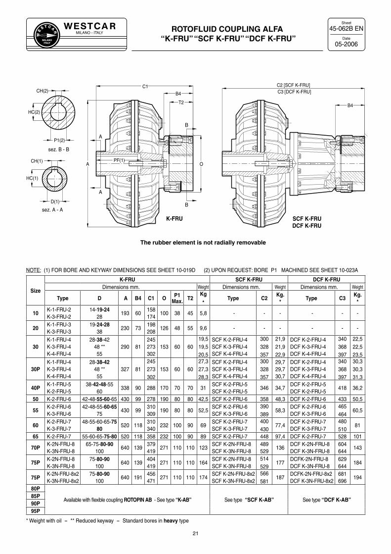
ROTOFLUID COUPLING ALFA “K-FRU” “SCF K-FRU” “DCF K-FRU”
45-062B EN
05-2006
21
sez. A - A
sez. B - B
A
A
B
B
A
D(1)
PF(1)O
T2
B4
P1(2)
B4
C1 C2 [SCF K-FRU]
CH(1)
HC(1)
CH(2)
HC(2)
C3 [DCF K-FRU]
SCF K-FRUDCF K-FRU
K-FRU
Size
K-FRU SCF K-FRU DCF K-FRUDimensions mm. Weight Dimensions mm. Weight Dimensions mm. Weight
Type D A B4 C1 O P1Max. T2
Kg
*Type C2
Kg.*
Type C3Kg.
*
10K-1-FRU-2K-3-FRU-2
14-19-2428
193 60158174
100 38 45 5,8 - - - - - -
20K-1-FRU-3K-3-FRU-3
19-24-2838
230 73198208
126 48 55 9,6 - - - - - -
30K-1-FRU-4K-3-FRU-4K-4-FRU-4
28-38-4248 **55
290 81245273302
153 60 6019,519,520,5
SCF K-2-FRU-4SCF K-3-FRU-4SCF K-4-FRU-4
300328357
21,921,922,9
DCF K-2-FRU-4DCF K-3-FRU-4DCF K-4-FRU-4
340368397
22,522,523,5
30PK-1-FRU-4K-3-FRU-4K-4-FRU-4
28-38-4248 **55
327 81245273302
153 60 6027,327,328,3
SCF K-2-FRU-4SCF K-3-FRU-4SCF K-4-FRU-4
300328357
29,729,730,7
DCF K-2-FRU-4DCF K-3-FRU-4DCF K-4-FRU-4
340368397
30,330,331,3
40PK-1-FRU-5K-2-FRU-5
38-42-48-5560
338 90 288 170 70 70 31SCF K-2-FRU-5SCF K-2-FRU-5
346 34,7DCF K-2-FRU-5DCF K-2-FRU-5
418 36,2
50 K-2-FRU-6 42-48-55-60-65 430 99 278 190 80 80 42,5 SCF K-2-FRU-6 358 48,3 DCF K-2-FRU-6 433 50,5
55K-2-FRU-6K-3-FRU-6
42-48-55-60-6575
430 99310309
190 80 80 52,5SCF K-2-FRU-6SCF K-3-FRU-6
390389
58,3DCF K-2-FRU-6DCF K-3-FRU-6
465464
60,5
60K-2-FRU-7K-3-FRU-7
48-55-60-65-7580
520 118310340
232 100 90 69SCF K-2-FRU-7SCF K-3-FRU-7
400430
77,4DCF K-2-FRU-7DCF K-3-FRU-7
480510
81
65 K-2-FRU-7 55-60-65-75-80 520 118 358 232 100 90 89 SCF K-2-FRU-7 448 97,4 DCF K-2-FRU-7 528 101
70PK-2N-FRU-8K-3N-FRU-8
65-75-80-90100
640 139379419
271 110 110 123SCF K-2N-FRU-8SCF K-3N-FRU-8
489529
136DCF K-2N-FRU-8DCF K-3N-FRU-8
604644
143
75PK-2N-FRU-8K-3N-FRU-8
75-80-90100
640 139404419
271 110 110 164SCF K-2N-FRU-8SCF K-3N-FRU-8
514529
177DCFK-2N-FRU-8DCF K-3N-FRU-8
629644
184
75PK-2N-FRU-8x2K-3N-FRU-8x2
75-80-90100
640 191456471
271 110 110 174SCF K-2N-FRU-8x2SCF K-3N-FRU-8x2
566581
187DCFK-2N-FRU-8x2DCF K-3N-FRU-8x2
681696
194
80P
Available with flexible coupling ROTOPIN AB - See type “K-AB” See type “SCF K-AB” See type “DCF K-AB”85P90P95P
* Weight with oil - ** Reduced keyway - Standard bores in heavy type
NOTE: (1) FOR BORE AND KEYWAY DIMENSIONS SEE SHEET 10-019D (2) UPON REQUEST: BORE P1 MACHINED SEE SHEET 10-023A
The rubber element is not radially removable
MILANO - ITALYW
E
S T C A
R
MILANOITALY
Sheet
Date
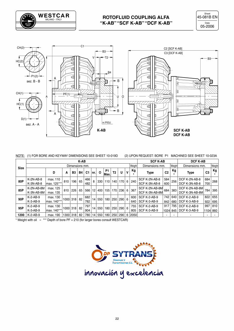
ROTOFLUID COUPLING ALFA “K-AB” “SCF K-AB” “DCF K-AB”
45-081B EN
05-2006
22
sez. A - A
sez. B - BA
AB
B
B4
T2
B3
O
V
U
B3
A
HC(1)
D(1)
CH(1) PF(1)
HC(2)
P1(2)
CH(2)
K-AB SCF K-ABDCF K-AB
nr.PIOLI
C1C2 [SCF K-AB]
C3 [DCF K-AB]
NOTE: (1) FOR BORE AND KEYWAY DIMENSIONS SEE SHEET 10-019D (2) UPON REQUEST: BORE P1 MACHINED SEE SHEET 10-023A
Size
K-AB SCF K-AB DCF K-ABDimensions mm. Weight Dimensions mm. Weight Dimensions mm. Weight
D A B3 B4 C1 nr. O P1Max. T2 U V
Kg*
Type C2Kg*
Type C3Kg*
80PK-2N-AB-8K-3N-AB-8
max. 110max. 125***
810 196 65466482
8 330 110 140 170 6 240SCF K-2N-AB-8SCF K-3N-AB-8
584600
256DCF K-2N-AB-8DCF K-3N-AB-8
684700
268
85PK-2N-AB-8MK-3N-AB-8M
max. 125max. 135
810 226 65 566 12 400 155 170 236 6 367SCF K-2N-AB-8MSCF K-3N-AB-8M
684 383DCF K-2N-AB-8MDCF K-3N-AB-8M
784 395
90PK-2-AB-9K-3-AB-9
max. 130max. 140***
1000 318 82682782
14 550 180 250 290 6600640
SCF K-2-AB-9SCF K-3-AB-9
742842
640680
DCF K-2-AB-9DCF K-3-AB-9
822922
655695
95PK-2-AB-9K-3-AB-9
max. 130max. 140***
1000 318 82797904
14 550 180 250 290 6755805
SCF K-2-AB-9SCF K-3-AB-9
9171024
795845
DCF K-2-AB-9 DCF K-3-AB-9
9971104
810860
1200 K-2-AB-9 max. 190 1300 318 82 780 14 550 180 250 290 6 2050 - - - - - -
* Weight with oil - *** Depth of bore PF = 210 (for larger bores consult WESTCAR)
MILANO - ITALYW
E
S T C A
R
MILANOITALY
Sheet
Date
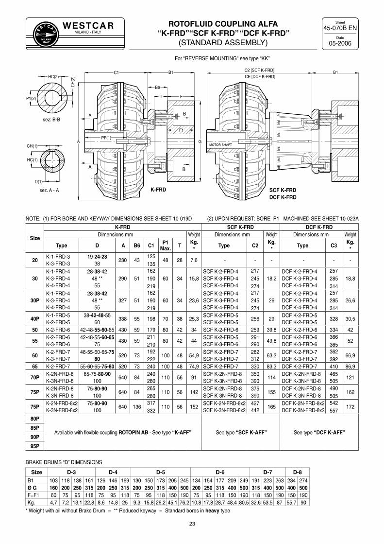
ROTOFLUID COUPLING ALFA “K-FRD”“SCF K-FRD” “DCF K-FRD”
(STANDARD ASSEMBLY)
45-070B EN
05-2006
23
NOTE: (1) FOR BORE AND KEYWAY DIMENSIONS SEE SHEET 10-019D (2) UPON REQUEST: BORE P1 MACHINED SEE SHEET 10-023A
B
B
sez: B-BA
A
sez. A - A
APF(1)
F
B1
T
G
F1
CH(1)
HC(1)
D(1)
C2 [SCF K-FRD]C1
P1(2)
CH
(2)HC(2)
B1CE [DCF K-FRD]
B6
K-FRD SCF K-FRDDCF K-FRD
MOTOR SHAFT
Size
K-FRD SCF K-FRD DCF K-FRDDimensions mm Weight Dimensions mm Weight Dimensions mm Weight
Type D A B6 C1 P1Max. T
Kg.*
Type C2Kg.
*Type C3
Kg.*
20K-1-FRD-3K-3-FRD-3
19-24-2838
230 43125135
48 28 7,6 - - - - - -
30K-1-FRD-4K-3-FRD-4K-4-FRD-4
28-38-4248 **55
290 51162190219
60 34 15,8SCF K-2-FRD-4SCF K-3-FRD-4SCF K-4-FRD-4
217245274
18,2DCF K-2-FRD-4DCF K-3-FRD-4DCF K-4-FRD-4
257285314
18,8
30PK-1-FRD-4K-3-FRD-4K-4-FRD-4
28-38-4248 **55
327 51162190219
60 34 23,6SCF K-2-FRD-4SCF K-3-FRD-4SCF K-4-FRD-4
217245274
26DCF K-2-FRD-4DCF K-3-FRD-4DCF K-4-FRD-4
257285314
26,6
40PK-1-FRD-5K-2-FRD-5
38-42-48-5560
338 55 198 70 38 25,3SCF K-2-FRD-5SCF K-2-FRD-5
256 29DCF K-2-FRD-5DCF K-2-FRD-5
328 30,5
50 K-2-FRD-6 42-48-55-60-65 430 59 179 80 42 34 SCF K-2-FRD-6 259 39,8 DCF K-2-FRD-6 334 42
55K-2-FRD-6K-3-FRD-6
42-48-55-60-6575
430 59211210
80 42 44SCF K-2-FRD-5SCF K-3-FRD-6
291290
49,8DCF K-2-FRD-6DCF K-3-FRD-6
366365
52
60K-2-FRD-7K-3-FRD-7
48-55-60-65-7580
520 73192222
100 48 54,9SCF K-2-FRD-7SCF K-3-FRD-7
282312
63,3DCF K-2-FRD-7DCF K-3-FRD-7
362392
66,9
65 K-2-FRD-7 55-60-65-75-80 520 73 240 100 48 74,9 SCF K-2-FRD-7 330 83,3 DCF K-2-FRD-7 410 86,9
70PK-2N-FRD-8K-3N-FRD-8
65-75-80-90100
640 84240280
110 56 91SCF K-2N-FRD-8SCF K-3N-FRD-8
350390
114DCF K-2N-FRD-8DCF K-3N-FRD-8
465505
121
75PK-2N-FRD-8K-3N-FRD-8
75-80-90100
640 84265280
110 56 142SCF K-2N-FRD-8SCF K-3N-FRD-8
375390
155DCF K-2N-FRD-8DCF K-3N-FRD-8
490505
162
75PK-2N-FRD-8x2K-3N-FRD-8x2
75-80-90100
640 136317332
110 56 152SCF K-2N-FRD-8x2SCF K-3N-FRD-8x2
427442
165DCF K-2N-FRD-8x2DCF K-3N-FRD-8x2
542557
172
80P
Available with flexible coupling ROTOPIN AB - See type “K-AFF” See type “SCF K-AFF” See type “DCF K-AFF”85P
90P
95P
BRAKE DRUMS “D” DIMENSIONS
Size D-3 D-4 D-5 D-6 D-7 D-8
B1 103 118 138 161 126 146 169 130 150 173 205 245 134 154 177 209 249 191 223 263 234 274Ø G 160 200 250 315 200 250 315 200 250 315 400 500 200 250 315 400 500 315 400 500 400 500F=F1 60 75 95 118 75 95 118 75 95 118 150 190 75 95 118 150 190 118 150 190 150 190Kg. 4,7 7,2 13,1 22,8 8,6 14,8 25 9,3 15,8 26,2 45,1 76,2 10,8 17,8 28,7 48,4 80,5 32,6 53,5 87 55,7 90
* Weight with oil without Brake Drum - ** Reduced keyway - Standard bores in heavy type
For “REVERSE MOUNTING" see type “KK”
MILANO - ITALYW
E
S T C A
R
MILANOITALY
Sheet
Date
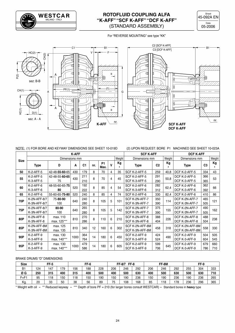
ROTOFLUID COUPLING ALFA “K-AFF” “SCF K-AFF” “DCF K-AFF”
(STANDARD ASSEMBLY)
45-092A EN
05-2006
24
NOTE: (1) FOR BORE AND KEYWAY DIMENSIONS SEE SHEET 10-019D (2) UPON REQUEST: BORE P1 MACHINED SEE SHEET 10-023A
sez. A - A
sez: B-B
B
B
A
A
F1PF(1)ACH(1)
HC
(1)
D(1)
HC(2)
CH
(2)
P(2
)
K-AFF SCF K-AFFDCF K-AFF
nr. nr.
B1
FV
C1
G
B1C2 [SCF K-AFF]
C3 [DCF K-AFF]
Size
K-AFF SCF K-AFF DCF K-AFFDimensions mm Weight Dimensions mm Weight Dimensions mm Weight
Type D A C1 nr. P1Max. V
Kg*
Type C2Kg*
Type C3Kg*
50 K-2-AFF-5 42-48-55-60-65 430 179 8 70 4 35 SCF K-2-AFF-5 259 40,8 DCF K-2-AFF-5 334 43
55K-2-AFF-5K-3-AFF-5
42-48-55-60-6575
430211210
8 70 4 45SCF K-2-AFF-5SCF K-3-AFF-5
291290
50,8DCF K-2-AFF-5DCF K-3-AFF-5
366365
53
60K-2-AFF-6K-3-AFF-6
48-55-60-65-7580
520192222
8 85 4 54SCF K-2-AFF-6SCF K-3-AFF-6
282312
62,4DCF K-2-AFF-6DCF K-3-AFF-6
362392
66
65 K-2-AFF-6 55-60-65-75-80 520 240 8 85 4 74 SCF K-2-AFF-6 330 82,4 DCF K-2-AFF-6 410 86
70PK-2N-AFF-8/7K-3N-AFF-8/7
75-80-90100
640240280
8 105 5 101SCF K-2N-AFF-7SCF K-3N-AFF-7
350390
114DCF K-2N-AFF-7DCF K-3N-AFF-7
465505
121
75PK-2N-AFF-8/7K-3N-AFF-8/7
80-90100
640265280
8 105 5 142SCF K-2N-AFF-7SCF K-3N-AFF-7
375390
155DCF K-2N-AFF-7DCF K-3N-AFF-7
490505
162
80PK-2N-AFF-8K-3N-AFF-8
max. 110max. 125***
810270286
8 110 6 210SCF K-2N-AFF-8SCF K-3N-AFF-8
388404
226DCF K-2N-AFF-8DCF K-3N-AFF-8
488504
238
85PK-2N-AFF-8MK-3N-AFF-8M
max. 125max. 135
810 340 12 160 6 302SCF K-2N-AFF-8MSCF K-3N-AFF-8M
458 318DCF K-2N-AFF-8MDCF K-3N-AFF-8M
558 330
90PK-2-AFF-9K-3-AFF-9
max. 130max. 140***
1000364764
14 180 6 450SCF K-2-AFF-9SCF K-3-AFF-9
424524
490DCF K-2-AFF-9DCF K-3-AFF-9
504604
505545
95PK-2-AFF-9K-3-AFF-9
max. 130max. 140***
1000479586
14 180 6 605SCF K-2-AFF-9SCF K-3-AFF-9
599706
645DCF K-2-AFF-9DCF K-3-AFF-9
679786
660710
BRAKE DRUMS “D” DIMENSIONS
Size FF-5 FF-6 FF-8/7 FF-8 FF-8M FF-9B1 124 147 179 156 188 228 206 246 292 206 246 292 255 304 333
Ø G 250 315 400 315 400 500 400 500 630 400 500 630 500 630 710F=F1 95 118 150 118 150 190 150 190 236 150 190 236 190 236 265 Kg. 20 33 50 38 56 89 75 108 168 85 118 178 236 296 365
* Weight with oil - ** Reduced keyway - *** Depth of bore PF = 210 (for larger bores consult WESTCAR) - Standard bores in heavy type
For “REVERSE MOUNTING" see type “KK”
MILANO - ITALYW
E
S T C A
R
MILANOITALY
Sheet
Date
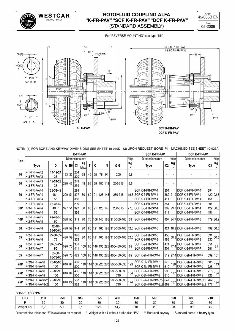
ROTOFLUID COUPLING ALFA “K-FR-PAV” “SCF K-FR-PAV” “DCF K-FR-PAV”
(STANDARD ASSEMBLY)
45-066B EN
05-2006
25
Size
K-FR-PAV SCF K-FR-PAV DCF K-FR-PAVDimensions mm Weight Dimensions mm Weight Dimensions mm Weight
Type D A B6 C1 P1Max. T Q I N Ø G
Kg.*
Type C2Kg.
*Type C3
Kg.*
10 K-1-FR-PAV-2K-3-FR-PAV-2
14-19-2428
193 35204220
38 45 55 78 94 200 5,8 - - - - - -
20K-1-FR-PAV-3K-3-FR-PAV-3
19-24-2838
230 43249259
48 55 69 100 118 250-315 9,6 - - - - - -
30 K-1-FR-PAV-4K-3-FR-PAV-4K-4-FR-PAV-4
28-38-4248 **55
290 51299327356
60 60 91 125 145 250-315 19,5SCF K-1-FR-PAV-4SCF K-3-FR-PAV-4SCF K-4-FR-PAV-4
354382411
21,9DCF K-1-FR-PAV-4DCF K-3-FR-PAV-4DCF K-4-FR-PAV-4
394422451
22,5
30PK-1-FR-PAV-4K-3-FR-PAV-4K-4-FR-PAV-4
28-38-4248 **55
327 51299327356
60 60 91 125 145 250-315 27,3SCF K-1-FR-PAV-4SCF K-3-FR-PAV-4SCF K-4-FR-PAV-4
354382411
29,7DCF K-1-FR-PAV-4DCF K-3-FR-PAV-4DCF K-4-FR-PAV-4
394422451
30,3
40P K-1-FR-PAV-5K-2-FR-PAV-5
42-48-5560
338 55 349 70 70 106 140 165 315-355-400 31 SCF K-2-FR-PAV-5 407 34,7 DCF K-2-FR-PAV-5 479 36,2
50 K-2-FR-PAV-642-48-
55-60-65430 59 344 80 80 121 160 185 315-355-400 42,5 SCF K-2-FR-PAV-6 424 48,3 DCF K-2-FR-PAV-6 499 50,5
55 K-2-FR-PAV-6K-3-FR-PAV-6
55-60-65-75
430 59376375
80 80 121 160 185 315-355-400 52,5SCF K-2-FR-PAV-6SCF K-3-FR-PAV-6
456455
58,3DCF K-2-FR-PAV-6DCF K-3-FR-PAV-6
531530
60,5
60 K-2-FR-PAV-7K-3-FR-PAV-7
60-65-75-80
520 73381411
100 90 146 195 225 400-450-500 69SCF K-2-FR-PAV-7SCF K-3-FR-PAV-7
471501
77,4DCF K-2-FR-PAV-7DCF K-3-FR-PAV-7
551581
81
65 K-2-FR-PAV-755-60-
65-75-80520 73 429 100 90 146 195 225 400-450-500 89 SCF K-2N-FR-PAV-7 519 97,4 DCF K-2N-FR-PAV-7 599 101
70PK-2N-FR-PAV-8K-3N-FR-PAV-8
75-80-90100
640 84460500
110 110 156 225 270 500-560-630 123SCF K-2N-FR-PAV-8SCF K-3N-FR-PAV-8
570610
136DCF K-2N-FR-PAV-8DCF K-3N-FR-PAV-8
685725
143
75PK-2N-FR-PAV-8K-3N-FR-PAV-8
75-80-90100
640 84485500
110 110 156 225 270500-560-630
710164
SCF K-2N-FR-PAV-8SCF K-3N-FR-PAV-8
595610
177DCF K-2N-FR-PAV-8DCF K-3N-FR-PAV-8
710725
184
75PK-2N-FR-PAV-8x2K-3N-FR-PAV-8x2
75-80-90100
640 136537552
110 110 156 225 270500-560-630
710174
SCF K-2N-FR-PAV-8x2SCF K-3N-FR-PAV-8x2
647662
187DCF K-2N-FR-PAV-8x2DCF K-3N-FR-PAV-8x2
762777
194
BRAKE DISC “PA”
Ø G 200 250 315 355 400 450 500 560 630 710F 30 30 30 30 30 30 30 30 30 30
Weight Kg. 3,7 5,7 9,1 12,5 14,7 18 23 28 36 45
Different disc thickness “F” is available on request - * Weight with oil without brake disc “PA” - ** Reduced keyway - Standard bores in heavy type
NOTE: (1) FOR BORE AND KEYWAY DIMENSIONS SEE SHEET 10-019D (2) UPON REQUEST: BORE P1 MACHINED SEE SHEET 10-023A
sez. B - B
sez. A - A
A
A
B
B
CH(1)
HC(1)
GNPF(1)
P(2)
CH(2)
HC(2)
A
D(1)
Q I
B6F=30 mm.
C1
T
C2 [SCF K-FR-PAV]C3 [DCF K-FR-PAV]
B6
FR
PAVPAV
FR4 mm.
K-FR-PAV SCF K-FR-PAVDCF K-FR-PAV
For “REVERSE MOUNTING" see type “KK”
MILANO - ITALYW
E
S T C A
R
MILANOITALY
Sheet
Date
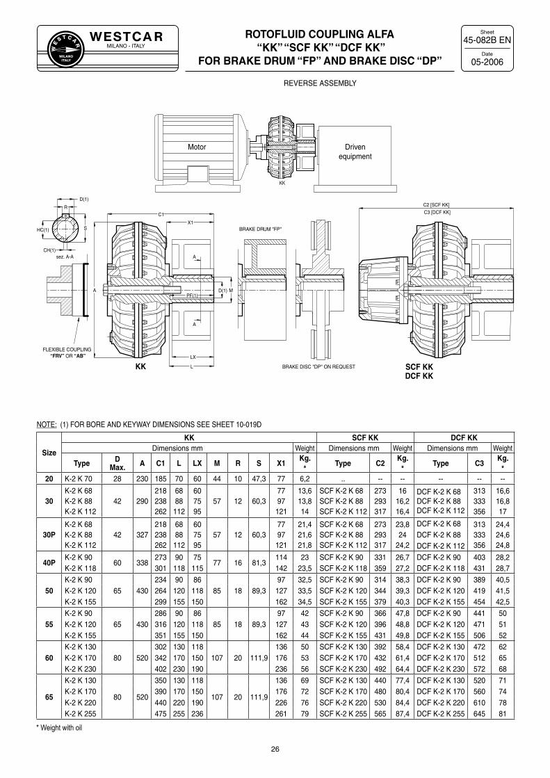
ROTOFLUID COUPLING ALFA “KK” “SCF KK” “DCF KK”
FOR BRAKE DRUM “FP” AND BRAKE DISC “DP”
45-082B EN
05-2006
26
NOTE: (1) FOR BORE AND KEYWAY DIMENSIONS SEE SHEET 10-019D
A
A
sez. A-ACH(1)
HC(1)
D(1)
C3 [DCF KK]C1
KK SCF KKDCF KK
BRAKE DRUM "FP"X1
LX
M
S
D(1)
R
BRAKE DISC "DP" ON REQUEST
A
L
PF(1)
C2 [SCF KK]
KK
FLEXIBLE COUPLING “FRV” OR “AB”
REVERSE ASSEMBLY
Motor Drivenequipment
Size
KK SCF KK DCF KKDimensions mm Weight Dimensions mm Weight Dimensions mm Weight
Type DMax. A C1 L LX M R S X1
Kg.*
Type C2Kg.
*Type C3
Kg.*
20 K-2 K 70 28 230 185 70 60 44 10 47,3 77 6,2 .. -- -- -- -- --
30K-2 K 68K-2 K 88K-2 K 112
42 290218238262
6888112
607595
57 12 60,37797
121
13,613,814
SCF K-2 K 68SCF K-2 K 88SCF K-2 K 112
273293317
1616,216,4
DCF K-2 K 68DCF K-2 K 88DCF K-2 K 112
313333356
16,616,817
30PK-2 K 68K-2 K 88K-2 K 112
42 327218238262
6888112
607595
57 12 60,37797
121
21,421,621,8
SCF K-2 K 68SCF K-2 K 88SCF K-2 K 112
273293317
23,824
24,2
DCF K-2 K 68 313333356
24,424,624,8
DCF K-2 K 88DCF K-2 K 112
40PK-2 K 90
60 338273 90 75
77 16 81,3114 23 SCF K-2 K 90 331 26,7 DCF K-2 K 90 403 28,2
K-2 K 118 301 118 115 142 23,5 SCF K-2 K 118 359 27,2 DCF K-2 K 118 431 28,7
50K-2 K 90
65 430234 90 86
85 18 89,397 32,5 SCF K-2 K 90 314 38,3 DCF K-2 K 90 389 40,5
K-2 K 120 264 120 118 127 33,5 SCF K-2 K 120 344 39,3 DCF K-2 K 120 419 41,5K-2 K 155 299 155 150 162 34,5 SCF K-2 K 155 379 40,3 DCF K-2 K 155 454 42,5
55K-2 K 90
65 430286 90 86
85 18 89,397 42 SCF K-2 K 90 366 47,8 DCF K-2 K 90 441 50
K-2 K 120 316 120 118 127 43 SCF K-2 K 120 396 48,8 DCF K-2 K 120 471 51K-2 K 155 351 155 150 162 44 SCF K-2 K 155 431 49,8 DCF K-2 K 155 506 52
60K-2 K 130
80 520302 130 118
107 20 111,9136 50 SCF K-2 K 130 392 58,4 DCF K-2 K 130 472 62
K-2 K 170 342 170 150 176 53 SCF K-2 K 170 432 61,4 DCF K-2 K 170 512 65K-2 K 230 402 230 190 236 56 SCF K-2 K 230 492 64,4 DCF K-2 K 230 572 68
65
K-2 K 130
80 520
350 130 118
107 20 111,9
136 69 SCF K-2 K 130 440 77,4 DCF K-2 K 130 520 71K-2 K 170 390 170 150 176 72 SCF K-2 K 170 480 80,4 DCF K-2 K 170 560 74K-2 K 220 440 220 190 226 76 SCF K-2 K 220 530 84,4 DCF K-2 K 220 610 78K-2 K 255 475 255 236 261 79 SCF K-2 K 255 565 87,4 DCF K-2 K 255 645 81
* Weight with oil
MILANO - ITALYW
E
S T C A
R
MILANOITALY
Sheet
Date
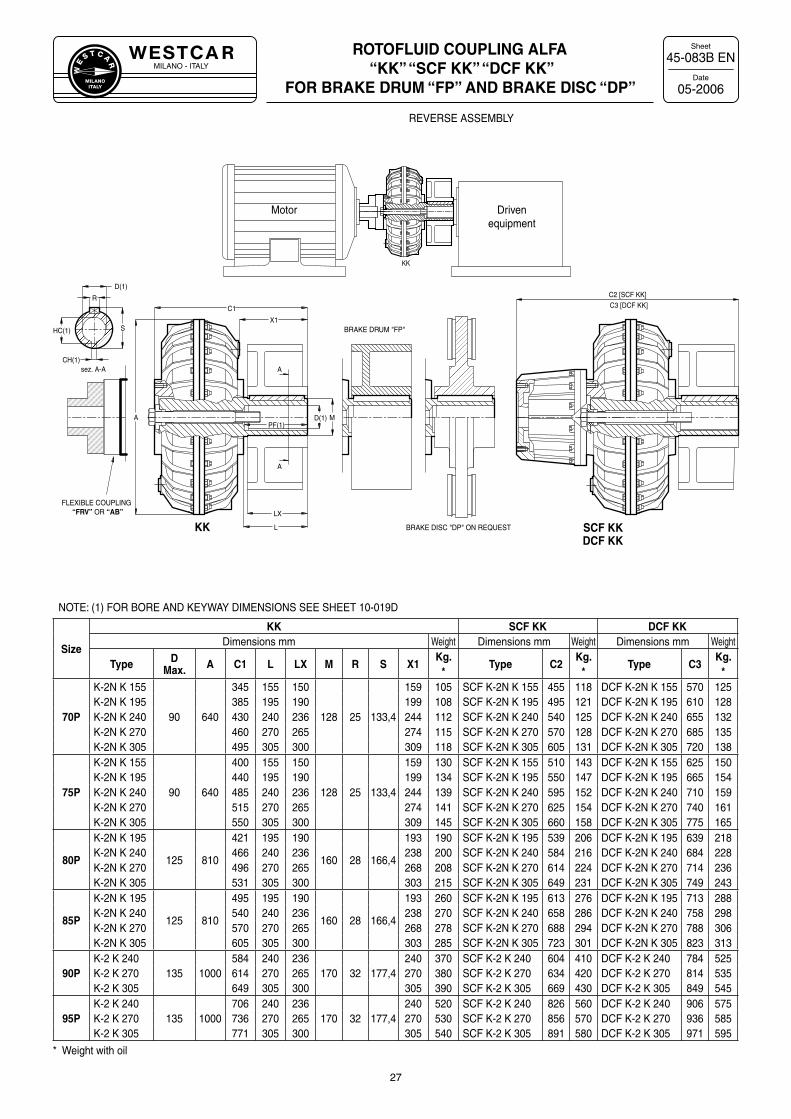
ROTOFLUID COUPLING ALFA “KK” “SCF KK” “DCF KK”
FOR BRAKE DRUM “FP” AND BRAKE DISC “DP”
45-083B EN
05-2006
27
NOTE: (1) FOR BORE AND KEYWAY DIMENSIONS SEE SHEET 10-019D
A
A
sez. A-ACH(1)
HC(1)
D(1)
C3 [DCF KK]C1
KK SCF KKDCF KK
BRAKE DRUM "FP"X1
LX
M
S
D(1)
R
BRAKE DISC "DP" ON REQUEST
A
L
PF(1)
C2 [SCF KK]
KK
FLEXIBLE COUPLING “FRV” OR “AB”
REVERSE ASSEMBLY
Motor Drivenequipment
Size
KK SCF KK DCF KKDimensions mm Weight Dimensions mm Weight Dimensions mm Weight
Type DMax. A C1 L LX M R S X1
Kg.*
Type C2Kg.
*Type C3
Kg.*
70P
K-2N K 155
90 640
345 155 150
128 25 133,4
159 105 SCF K-2N K 155 455 118 DCF K-2N K 155 570 125K-2N K 195 385 195 190 199 108 SCF K-2N K 195 495 121 DCF K-2N K 195 610 128K-2N K 240 430 240 236 244 112 SCF K-2N K 240 540 125 DCF K-2N K 240 655 132K-2N K 270 460 270 265 274 115 SCF K-2N K 270 570 128 DCF K-2N K 270 685 135K-2N K 305 495 305 300 309 118 SCF K-2N K 305 605 131 DCF K-2N K 305 720 138
75P
K-2N K 155
90 640
400 155 150
128 25 133,4
159 130 SCF K-2N K 155 510 143 DCF K-2N K 155 625 150K-2N K 195 440 195 190 199 134 SCF K-2N K 195 550 147 DCF K-2N K 195 665 154K-2N K 240 485 240 236 244 139 SCF K-2N K 240 595 152 DCF K-2N K 240 710 159K-2N K 270 515 270 265 274 141 SCF K-2N K 270 625 154 DCF K-2N K 270 740 161K-2N K 305 550 305 300 309 145 SCF K-2N K 305 660 158 DCF K-2N K 305 775 165
80P
K-2N K 195
125 810
421 195 190
160 28 166,4
193 190 SCF K-2N K 195 539 206 DCF K-2N K 195 639 218K-2N K 240 466 240 236 238 200 SCF K-2N K 240 584 216 DCF K-2N K 240 684 228K-2N K 270 496 270 265 268 208 SCF K-2N K 270 614 224 DCF K-2N K 270 714 236K-2N K 305 531 305 300 303 215 SCF K-2N K 305 649 231 DCF K-2N K 305 749 243
85P
K-2N K 195
125 810
495 195 190
160 28 166,4
193 260 SCF K-2N K 195 613 276 DCF K-2N K 195 713 288K-2N K 240 540 240 236 238 270 SCF K-2N K 240 658 286 DCF K-2N K 240 758 298K-2N K 270 570 270 265 268 278 SCF K-2N K 270 688 294 DCF K-2N K 270 788 306K-2N K 305 605 305 300 303 285 SCF K-2N K 305 723 301 DCF K-2N K 305 823 313
90PK-2 K 240
135 1000584 240 236
170 32 177,4240 370 SCF K-2 K 240 604 410 DCF K-2 K 240 784 525
K-2 K 270 614 270 265 270 380 SCF K-2 K 270 634 420 DCF K-2 K 270 814 535K-2 K 305 649 305 300 305 390 SCF K-2 K 305 669 430 DCF K-2 K 305 849 545
95PK-2 K 240
135 1000706 240 236
170 32 177,4240 520 SCF K-2 K 240 826 560 DCF K-2 K 240 906 575
K-2 K 270 736 270 265 270 530 SCF K-2 K 270 856 570 DCF K-2 K 270 936 585K-2 K 305 771 305 300 305 540 SCF K-2 K 305 891 580 DCF K-2 K 305 971 595
* Weight with oil