fluid dynamics: an emerging route for the scalable production of graphene in the last ... · ·...
TRANSCRIPT
1
Fluid dynamics: an emerging route for the scalable production of
graphene in the last five years
Min Yi1 and Zhigang Shen2
1 Institute of Materials Science, Technische Universität Darmstadt, Darmstadt 64287,
Germany.
2 Beijing Key Laboratory for Powder Technology Research & Development, Beihang
University (BUAA), Beijing 100191, China.
E-mail: [email protected]; [email protected]

2
Abstract
Bulk applications of graphene in fields such as advanced composites, conductive ink,
and energy storage require cheap and scalable graphene. Fortunately, in the last
decade, liquid-phase exfoliation of graphite to give pristine graphene has been
thought as a promising way to massive production of graphene at high efficiency and
low cost, in terms of the cheap and abundant graphite source and a variety of
cost-effective exfoliation techniques. Though many exfoliation techniques are
available so far, this article will highlight the recent progress of fluid dynamics route
which emerges as a promising scalable and efficient way for graphene production in
the last five years. The emphasis is set on vortex fluidic devices and pressure- and
mixer-driven fluid dynamics, with our perspectives on the latest progress, exfoliation
mechanism, and some key issues that require further study in order to realize
industrial applications.
Contents
1. Introduction ........................................................................................................................... 3
2. Vortex fluidic device (VFD) ................................................................................................. 5
3. Pressure-driven fluid dynamics (PFD) .................................................................................. 7
4. Mixer-driven fluid dynamics (MFD) .................................................................................... 8
5. Conclusions and perspectives.............................................................................................. 12
References ............................................................................................................................... 14

3
1. Introduction
Due to its exceptional properties and intriguing applications, graphene has attracted
intensive interests in the advanced science and technology. The last decade has
witnessed many breakthroughs in research on graphene. A serial of novel properties
and promising applications are reported in succession [1-7]. With the achievement by
the graphene community in recent years, it has been thought that graphene will
become the next subversive technology, substitute some of the currently used
materials, and result in a new market and thus the scientific and technological
revolution. However, the scalable and cost-effective production of graphene still
remains as a critical issue for realizing its commercialization. If graphene cannot be
produced at low cost and high efficiency, its commercial and widespread use could be
lowered down or even ultimately hindered.
Since graphene was discovered in 2004 [8], a significant advance in the mass
production of this material has been achieved, as shown in Fig. 1. A great many
methods have been proposed to produce graphene [9-35], among which one can
choose a suitable one for specified applications. The bottom-up methods [10, 15, 18,
23, 25-35] such as chemical vapour deposition and epitaxial growth can produce high
quality, large-size and thickness-controllable graphene. The resulted graphene is ideal
for fabricating graphene electronics, field-effect transistors, flexible transparent
electrodes, functional touch-screen panel device, etc. However, these substrate-based
techniques suffer from the limited scale and high cost, and cannot meet the
requirement of macroscopic quantities of graphene for applications such as advanced
composites, coatings, conductive ink, and energy storage. Fortunately, liquid-phase
exfoliation (LPE) of graphite to give graphene has been recently proved as a scalable
method [2, 3, 9, 12, 13, 16, 17, 19-22, 36-87]. This method uses the cheap and
abundant graphite flakes as the precursor. The graphene products generated by this
method can fit the requirement of scalability, reproducibility, processability, and low
production cost. Though the graphene quality by this method is a question, the
definition on the graphene quality should be highly dependent on the specified

4
application. For example, in the applications for high catalytic activity [88, 89] and
high storage of capacitive charges [90], the graphene with edge defects are preferable.
Graphene nanomesh with porous structure is desired for semiconductivity applications
which require a tunable bandgap [78, 91-93]. Therefore, the LPE method is very
promising. It should be noted that the LPE method depends on the exfoliation medium
and the exfoliation technique. The exfoliation medium, such as suitable organic
solvents, surfactant/water solutions, aromatic solvents, ionic liquid, etc., has been
discussed in several art-to-date review [9, 12, 14, 16, 17, 20]. The widely used
exfoliation technique is sonication, which has also been reviewed recently [13, 41, 94].
The sonication depends on the liquid cavitation for exfoliation. However, sonication
induced cavitation is a relatively harsh process which can produce high local
temperature (~ several thousand K), extreme pressure (~ several thousand atm), and
rapid heating/cooling rates (~ several billion K/s) [95-97]. These harsh conditions
involved in cavitation could result in damage to the graphene. Thus, the graphene
produced by sonication has been verified to have much more defects as expected [74,
98-100]. Moreover, the distribution and intensity of the sonication-induced cavitation
are highly dependent on the vessel size and shape which often induce localized
cavitation pictures [101-104]. If the position of the ultrasonic vibration source is fixed,
the cavitation field in the liquid is almost static. These drawbacks are not favorable for
efficient exfoliation and a large quantity of graphite flakes which settle down to the
bottom still remain unexfoliated. In addition, in the literatures, sonic tips can only
effectively process volumes no larger than a few 100 mL leading to low production
rates. While sonic baths can be used to process hundreds of millilitres, the power
transfer from bath to liquid is relatively poor, leading to long exfoliation times and so
low production rates. Another route for efficiently transferring mechanical energy
directly into the liquid is desired.
Apart from sonication, fluid dynamics has emerged as a novel exfoliation technique
for scalable production of graphene in the recent five years. Within the fluid dynamics,
graphite flakes can move with the liquid and thus can be exfoliated repeatedly at
different position. And multiple fluid dynamic events are responsible for exfoliation.
These features are intrinsically different from that of sonication, rendering it as a
potentially efficient technique. Hence, keeping those key factors in mind, this progess
report will examine three promising fluid dynamics based exfoliation routes (vortex

5
fluidics, pressure and mixer driven fluid dynamics) and highlighting their recent
progress and challenges.
2. Vortex fluidic device (VFD)
In order to avoid the graphene defects and solvents degradation induced by cavitation
in sonication, a VFD is developed to generate a less energy intensive shear process for
exfoliating graphite. The VFD is schematized in Fig. 2a. It consists of a tube open at
one end. When it is rapidly rotated, intense shear will be generated in the resulting thin
films with finite sub-millilitre volumes of liquid. The shear fluidic film can be
controlled by adjusting the speed and orientation of the tube, and other operating
parameters [105]. According to the fluid dynamics [106], a rapidly rotating fluid can
generate the boundary and shear layers parallel to the axis of rotation, named as
Stewartson/Ekman layers. Within this layer, the liquid flow is upwards at the internal
surface of the rotating tube, and downwards close to the liquid surface, as shown in
Fig. 2a. Graphene dispersed in N-methyl-pyrrolidone (NMP) was successfully
produced via exfoliating graphite by the shear vortex fluidic films in the ‘confined
mode’ of operation of the VFD (without jet feeds in Fig. 2a).[58]. The graphite flakes
dispersed in NMP will initially accelerate to the walls of the tube by the large
centrifugal force. Then the partial lifting and slippage on the tube wall are responsible
for the exfoliation mechanism, as shown in Fig. 2b and c. The slippage process can be
highlighted by the “finger print” of partially stacked graphene in Fig. 2e. This slippage
process requires the individual sheets to be partially lifted from the surface of the bulk
material at some point to provide the necessary lateral force to start the slippage (Fig.
2b). Meanwhile, the graphite flakes were pushed against the tube wall by the
centrifugal force and experienced a shear induced displacement along the tube,
resulting in exfoliation at the tube surface (Fig. 2c).
In contrast, by using the ‘continuous flow mode’ of the VFD, graphene based
hybrid materials [72] and functionalized graphene [107] can also be readily produced.
In the ‘continuous flow mode’, another jet feeds can deliver liquid into the rotating
tube (Fig. 2a). This will generate additional shear is in the thin films by the viscous
drag as the liquid whirls along the tube. As shown in Fig. 3, the ‘confined mode’ is
firstly used to exfoliate graphite into multi-layer graphene in water. Then in the

6
‘continuous flow mode’, a feed jet at the base of the tube is used to deliver the
recirculating liquid of graphene and microalgae mixed suspension. With this route, the
multi-layer graphene sheets can be decorated on the surface of microalgal cells.
Following the same idea, Tran et al. [108] applied a Taylor-Couette flow reactor to
generate the vortex flow for exfoliating graphite flakes, as schematized in Fig. 4. In
the reactor, the mixture of graphite and solvent is sheared between a rapidly rotating
inner cylinder and stationary outer cylinder. Thus the vortex flow induced high wall
shear stress and pressure can be utilized to exfoliate graphite flakes. It is demonstrated
that this method can efficiently produce few-layer graphene with low degree of defects.
However, the gap between these two cylinders is only 2.5 mm, limiting the
throughput.
This VFD offers an alternative and tunable low-energy source for mild exfoliation
and thus high-quality graphene. But the vortex fluidic film or the gap between is
extremely thin (in the millimeter order), which limits the quantity of graphite used for
exfoliation and the graphene output.
shown in Fig. 2e-g and Fig. 5a and b. This is due to that the weak shear force
generated by VFD can only exfoliate smaller graphite flakes; because the collective
van der Waals interaction between layers for larger graphene flakes is much higher.
The thickness of graphene prepared by VFD changes from less than 1 nm to more than
20 nm, as shown in Fig. 2f and g and Fig. 5b. However, the number of these
transmission electron microscopy (TEM) and atomic force microscopy (AFM) images
in the literatures are too small to give a statistical analysis of the distribution of sheet
size. Since the graphene lateral size and thickness can determine whether graphene can
be integrated into practical devices and its ultimate properties are attainable, it is
highly recommended to obtain the size distribution of graphene prepared by VFD in
the near future. As for the defects, it is anticipated that VFD generates weak shear
force and it will not damage graphene. But there are only Raman spectra results (Fig.
5c) in this aspect. A deeper study by means of different microscopic and spectral
techniques is required for the determination of defects or oxides in the graphene
prepared by VFD, in order to establish VFD as a really defect-free method.
7
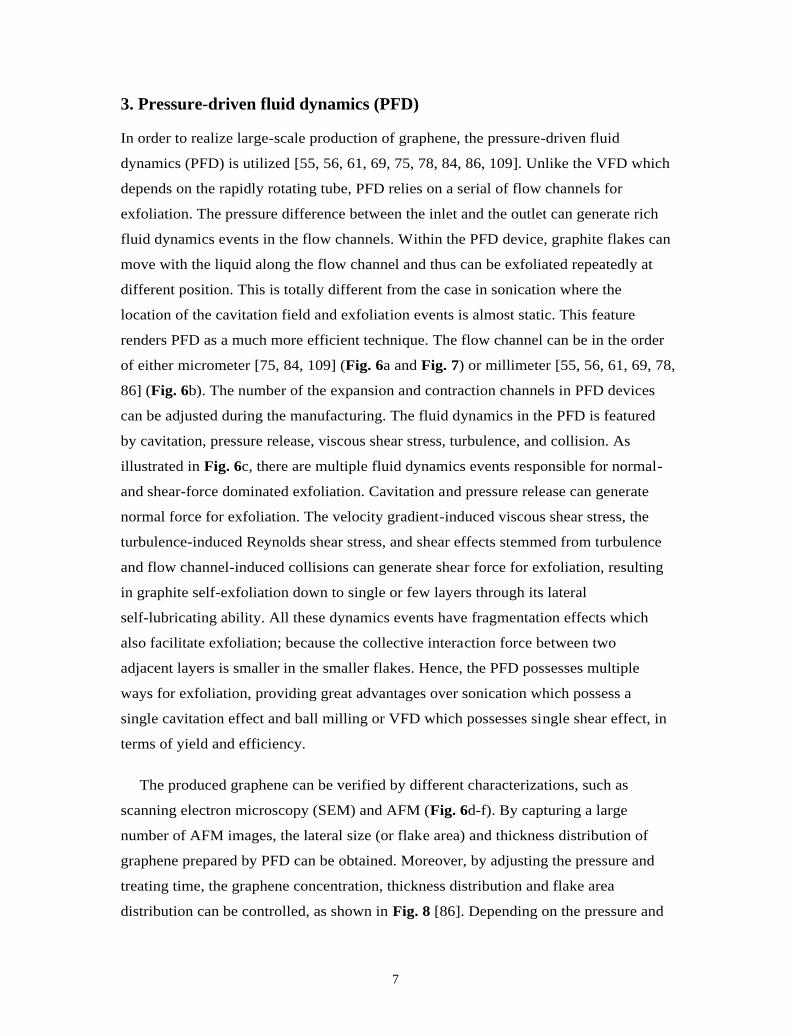
3. Pressure-driven fluid dynamics (PFD)
In order to realize large-scale production of graphene, the pressure-driven fluid
dynamics (PFD) is utilized [55, 56, 61, 69, 75, 78, 84, 86, 109]. Unlike the VFD which
depends on the rapidly rotating tube, PFD relies on a serial of flow channels for
exfoliation. The pressure difference between the inlet and the outlet can generate rich
fluid dynamics events in the flow channels. Within the PFD device, graphite flakes can
move with the liquid along the flow channel and thus can be exfoliated repeatedly at
different position. This is totally different from the case in sonication where the
location of the cavitation field and exfoliation events is almost static. This feature
renders PFD as a much more efficient technique. The flow channel can be in the order
of either micrometer [75, 84, 109] (Fig. 6a and Fig. 7) or millimeter [55, 56, 61, 69, 78,
86] (Fig. 6b). The number of the expansion and contraction channels in PFD devices
can be adjusted during the manufacturing. The fluid dynamics in the PFD is featured
by cavitation, pressure release, viscous shear stress, turbulence, and collision. As
illustrated in Fig. 6c, there are multiple fluid dynamics events responsible for normal-
and shear-force dominated exfoliation. Cavitation and pressure release can generate
normal force for exfoliation. The velocity gradient-induced viscous shear stress, the
turbulence-induced Reynolds shear stress, and shear effects stemmed from turbulence
and flow channel-induced collisions can generate shear force for exfoliation, resulting
in graphite self-exfoliation down to single or few layers through its lateral
self-lubricating ability. All these dynamics events have fragmentation effects which
also facilitate exfoliation; because the collective interaction force between two
adjacent layers is smaller in the smaller flakes. Hence, the PFD possesses multiple
ways for exfoliation, providing great advantages over sonication which possess a
single cavitation effect and ball milling or VFD which possesses single shear effect, in
terms of yield and efficiency.
The produced graphene can be verified by different characterizations, such as
scanning electron microscopy (SEM) and AFM (Fig. 6d-f). By capturing a large
number of AFM images, the lateral size (or flake area) and thickness distribution of
graphene prepared by PFD can be obtained. Moreover, by adjusting the pressure and
treating time, the graphene concentration, thickness distribution and flake area
distribution can be controlled, as shown in Fig. 8 [86]. Depending on the pressure and

8
treating time, the flake area and thickness distribution can be changed. As the treating
time is increased, the thickness distribution becomes narrower and shifts to lower
values Fig. 8a). For example, in the 0.5 h sample, flakes with thickness <3 nm (less
than 10 layers) occupies ~80%. The percentage of thin flakes with thickness <1.5 nm
(less than 5 layers) of the 0.5 h, 4 h, and 8 h samples is 29%, 63%, and 79%,
respectively. In contrast, the flake area sharply moves to small values. Fig. 8b presents
that over 85% flakes are with area less than 105 nm2 in the 8 h sample. The mean value
of the flake area has decreased by an order of magnitude in comparison with that in the
0.5 h sample. These results on size distribution establish PFD as a controllable method
for preparing graphene with specified size. As for the defects, only Raman results on
the graphene-based films are available [86, 109], which indicate low-level basal plane
defects. Nevertheless, microscopic study on the individual flakes by scanning
tunneling microscopy (STM) and X-ray photoelectron spectroscopy (XPS) is still
required to get more detailed information on the atomic structure and chemical
components of the basal plane of graphene prepared by PFD.
Fig. 8c shows that higher pressure leads to higher yield of graphene. These results
are useful for scaling up this technique from 10 L per pot in laboratory to several
hundred liters in industry. Most interestingly, if pressure is increased to higher values
(e.g. 30 MPa), this PFD technique can be used to produce graphene nanomesh [78],
which recently emerges as a novel graphene nanostructure with bandgap that is large
enough for room-temperature transistor operation [91, 92]. The mechanism is the
combination of exfoliation and perforation of the graphene sheets (Fig. 9a). The
obtained graphene nanomesh is shown in Fig. 9b and c. It is estimated that the total
area of the pores within 1 m2 nanomesh is ~0.15 m2 and the pore density is ~22
m-2. This provides a novel route for large-scale production of graphene nanomesh.
4. Mixer-driven fluid dynamics (MFD)
Another recently emerging method is the mixer-driven fluid dynamics (MFD). The
device for realizing this method is relatively simple and easily available. A
commercial available rotor/stator mixer can be used for graphene production [79, 80],
as shown in Fig. 10. The head of the mixer is constituted by a rotor and a stator as the
critical component for exfoliation. The rotor diameters (Fig. 10b and c) can be
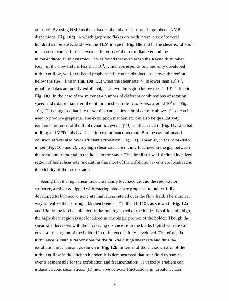
9
adjusted. By using NMP as the solvents, the mixer can result in graphene-NMP
dispersions (Fig. 10d), in which graphene flakes are with lateral size of several
hundred nanometers, as shown the TEM image in Fig. 10e and f. The shear exfoliation
mechanism can be further revealed in terms of the rotor diameter and the
mixer-induced fluid dynamics. It was found that even when the Reynolds number
ReMix of the flow field is less than 104, which corresponds to a not fully developed
turbulent flow, well-exfoliated graphene still can be obtained, as shown the region
below the ReMix line in Fig. 10g. But when the shear rate �̇� is lower than 104 s-1,
graphite flakes are poorly exfoliated, as shown the region below the �̇�=104 s-1 line in
Fig. 10g. In the case of the mixer at a number of different combinations of rotating
speed and rotator diameter, the minimum shear rate �̇�min is also around 104 s-1 (Fig.
10h). This suggests that any mixer that can achieve the shear rate above 104 s-1 can be
used to produce graphene. The exfoliation mechanism can also be qualitatively
explained in terms of the fluid dynamics events [79], as illustrated in Fig. 11. Like ball
milling and VFD, this is a shear-force dominated method. But the cavitation and
collision effects also favor efficient exfoliation (Fig. 11). However, in the rotor-stator
mixer (Fig. 10b and c), very high shear rates are mainly localized in the gap between
the rotor and stator and in the holes in the stator. This implies a well-defined localized
region of high shear rate, indicating that most of the exfoliation events are localized in
the vicinity of the rotor-stator.
Seeing that the high shear rates are mainly localized around the rotor/stator
structure, a mixer equipped with rotating blades are proposed to induce fully
developed turbulence to generate high shear rate all over the flow field. The simplest
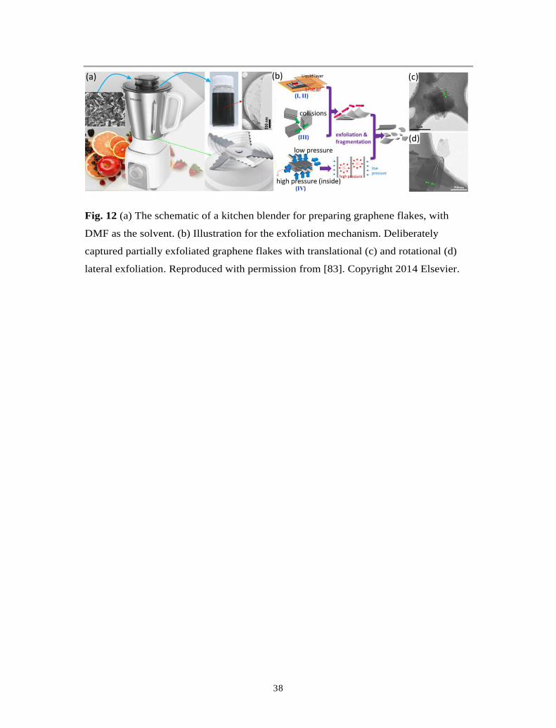
way to realize this is using a kitchen blender [71, 81, 83, 110], as shown in Fig. 12a
and 13a. In the kitchen blender, if the rotating speed of the blades is sufficiently high,
the high-shear region is not localized in any single portion of the holder. Though the
shear rate decreases with the increasing distance from the blade, high shear rate can
cover all the region of the holder if a turbulence is fully developed. Therefore, the
turbulence is mainly responsible for the full-field high shear rate and thus the
exfoliation mechanism, as shown in Fig. 12b. In terms of the characteristics of the
turbulent flow in the kitchen blender, it is demonstrated that four fluid dynamics
events responsible for the exfoliation and fragmentation: (I) velocity gradient can
induce viscous shear stress; (II) intensive velocity fluctuations in turbulence can
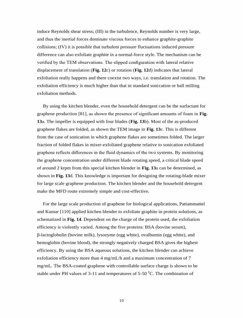
10
induce Reynolds shear stress; (III) in the turbulence, Reynolds number is very large,
and thus the inertial forces dominate viscous forces to enhance graphite-graphite
collisions; (IV) it is possible that turbulent pressure fluctuations induced pressure
difference can also exfoliate graphite in a normal-force style. The mechanism can be
verified by the TEM observations. The slipped configuration with lateral relative
displacement of translation (Fig. 12c) or rotation (Fig. 12d) indicates that lateral
exfoliation really happens and there coexist two ways, i.e. translation and rotation. The
exfoliation efficiency is much higher than that in standard sonication or ball milling
exfoliation methods.
By using the kitchen blender, even the household detergent can be the surfactant for
graphene production [81], as shown the presence of significant amounts of foam in Fig.
13a. The impeller is equipped with four blades (Fig. 13b). Most of the as-produced
graphene flakes are folded, as shown the TEM image in Fig. 13c. This is different
from the case of sonication in which graphene flakes are sometimes folded. The larger
fraction of folded flakes in mixer-exfoliated graphene relative to sonication exfoliated
graphene reflects differences in the fluid dynamics of the two systems. By monitoring
the graphene concentration under different blade rotating speed, a critical blade speed
of around 2 krpm from this special kitchen blender in Fig. 13a can be determined, as
shown in Fig. 13d. This knowledge is important for designing the rotating-blade mixer
for large scale graphene production. The kitchen blender and the household detergent
make the MFD route extremely simple and cost-effective.
For the large scale production of graphene for biological applications, Pattammattel
and Kumar [110] applied kitchen blender to exfoliate graphite in protein solutions, as
schematized in Fig. 14. Dependent on the charge of the protein used, the exfoliation
efficiency is violently varied. Among the five proteins: BSA (bovine serum),
β-lactoglobulin (bovine milk), lysozyme (egg white), ovalbumin (egg white), and
hemoglobin (bovine blood), the strongly negatively charged BSA gives the highest
efficiency. By using the BSA aqueous solutions, the kitchen blender can achieve
exfoliation efficiency more than 4 mg/mL/h and a maximum concentration of 7
mg/mL. The BSA-coated graphene with controllable surface charge is shown to be
stable under PH values of 3-11 and temperatures of 5-50 0C. The combination of
11
kitchen blender and proteins makes MFD as an effective tool for scalable and
biological production of graphene in water.
As for the size distribution of graphene flakes prepared by MFD, Varrla et al. [81]
and Yi et al. [83] have used AFM to perform statistical analysis. Varrla et al. [81]
adopted a rotation speed of 18 krpm and a treatment of 60 min to prepare graphene.
The AFM-based statistical distributions of length (L) and layer number (N) are shown
in Fig. 13e and f, respectively. The average length is found to be around 320 nm. The
average layer number is around 6 [81]. In contrast, Yi et al. adopted a rotation speed of
5 krpm, and investigated the effect of preparation time on the size distribution of the
resultant graphene flakes [83]. Fig. 15 shows the AFM-based statistical results for
flakes’ dimensions. Area rather than length or width is chosen, because most graphene
flakes are irregularly shaped and measuring their length or width is difficult. As shown
in Fig. 15a, the number fraction of ≤1.5-nm-thick flakes exceeds 80% for all the
preparation time, reaching a high value of ~92% at 3 h. Additionally, the number
fraction of ≤1 nm-thick graphene flakes approximately keeps constant between 14.6%
and 20% for all the preparation time. The flake area notably decreases with preparation
time, resulting in a shift in the area distribution towards lower values, as shown in Fig.
15b. Based on these statistical data, the average thickness per flake, <t>, and the
average area per flake, <A>, can be calculated, as shown in Fig. 15c. <t> hardly varies
at all and maintains at ~1.5 nm, corresponding to an average layer number of <5.
Nevertheless, the thickness distribution shifts towards lower values as preparation time
increases, as illustrated in Fig. 15a. In contrast, <A> decreases with preparation time,
falling from ~2.4 m2 at 0.5 h to ~0.1 m2 at 8 h. By fitting <A> as a function of
preparation time, an inversely-proportional relationship appears, as shown in Fig. 15d.
For the biographene produced in water/proteins solutions by MFD in the kitchen
blender, Pattammattel and Kumar [110] calculated the average layer number and
lateral size as a function of exfoliation time, as shown in Fig. 16b and c. The average
layer number is estimated as ~3.6 in despite of the exfoliation time (Fig. 16b). The
average size is ~0.5 µm and appears to be highly uniform, different from the results of
Varrla et al. [81] and Yi et al. [83]. The reason is attributed to the method.
Pattammattel and Kumar [110] used the Raman data to obtain the size information by
an empirical equation. In contrast, Varrla et al. [81] and Yi et al. [83] directly
measured the size by AFM or TEM.

12
The defects and oxides of graphene prepared by MFD were studied by XPS and
Raman mapping, as shown in Fig. 16 [110] and Fig. 17 [83]. By statistical analysis of
the Raman intensity ratio, Pattammattel and Kumar [110] pointed that the biographene
produce by MFD is only of minor edge defects (Fig. 16d). The XPS results in Fig. 17b
show the same bonds and similar composition in the pristine graphite and
graphene-based film, indicating that the low level of oxides in graphene are caused not
by residual solvent or oxidation but by water, CO2 or oxygen from the atmosphere.
These prove that MFD does not chemically functionalize the graphene flakes. By
using Raman mapping technique, individual graphene flake can be captured and its
Raman spectrum can be obtained, as shown in Fig. 17a and c. In Fig. 17c, the 2D
bands in Raman spectra of flake #1 and #2 reflect the graphene nature [22, 111, 112].
However, there are no D bands and the G bands are not remarkably widened. This
indicates that the flakes are almost free of basal plane defects. For the precise
examination of the local defects or atomic structure, STM and high-resolution TEM
characterizations are further required.
5. Conclusions and perspectives
Since the second half of 2011 when the virgin idea of producing graphene by
utilizing the rich flow events in fluid dynamics was firstly initiated,[55, 56] huge
progress has been made during the last five years. Various methods for generating
fluid dynamics have been proposed in order to explore an efficient and scalable route
for graphene production, such as vortex fluidics, mixer, blender, high pressure, etc.
Compared to the widely used cavitation-dominated sonication for producing graphene,
fluid dynamics possess multiple exfoliation effects originated from the shear,
cavitation, collision, and pressure release. Therefore, fluid dynamics are far more
efficient than sonication routes and shows great technological potential in the near
future. Considering the main factors for industrialization of graphene production, i.e.
production efficiency, production cost, scalability, reproducibility, processability, etc.,
the recently emerging fluid dynamics route is very promising. With the continuous
effort in fluid dynamics for graphene production, many exciting results and new
methods have so far been reported and several technologies are currently envisioned.
We believe that the recently emerging fluid dynamics route provides a significant step
in the direction of making the commercial availability of large quantities of

13
high-quality graphene. To proceed from discovery to a commercialized technology,
many issues remain to be further explored, a partial list of which includes:
(1) How can we control and optimize the exfoliation effects in fluid dynamics, so
that the harsh and violent effects can be lowered to a minimum level? For example,
though cavitation can exfoliate graphite into graphene flakes, it induces extremely
high local temperature and pressure [95-97], which can result in defected graphene. In
contrast, relying on the lateral exfoliation mechanism, exfoliation by shear force is
much milder. In PFD and the local region near the rotating blade in MFD, high-speed
fluid can generate cavitation. A deep understanding and precise design of the flow
field in PFD and MFD are critical for eliminating the cavitation region and achieving
high shear rates throughout the flow field.
(2) How to achieve monolayer dominated and large-size graphene products by fluid
dynamics still remains challenging. Exfoliation in fluid dynamics is always
accompanied with fragmentation that is not desired for producing large-size graphene.
How to minimize the fragmentation effects should be considered. The average layer
number and lateral size of graphene produced by fluid dynamics are 3-5 and several
hundred nanometers, respectively. It indicates the case of few-layer graphene. The
control of graphene size may be possible by combining fluid dynamic methods and
specified centrifugation strategy [59, 113-116].
(3) The nature of defects induced by fluid dynamics requires detailed investigations.
Currently a consensus has been reached on the conclusion of edge-dominated defects
in graphene produced by fluid dynamics. But the conclusion is almost based on the
Raman spectra of filtered graphene films, not the single graphene flake. In the filtered
film, the Raman signal is a superposition of contributions from many single- and
few-layer graphene flakes. It is suggested microscopic study on the individual flakes
by STM and XPS to be carried out, in order to get more detailed information on the
atomic structure and chemical components of the basal plane of graphene prepared by
fluid dynamics.
(4) Other simple routes for generating fluid dynamics should be explored. As the
schematics shown in Fig. 18, random shake and liquid spray may be another two
possible routes. It is anticipated that the fluid dynamics events involved in the process

14
of random shake and liquid spray can generate viscous shear, turbulence, collision, and
pressure release to mildly exfoliate graphite into graphene flakes.
(5) Are the current fluid dynamic methods ready for industrial scale-up or ‘blip on
the oscilloscope’? The VFD route with weak shear force can prepare high-quality
graphene, but the small throughput limits the scalable production. Though with high
efficiency, the PFD device depends on high pressure and small flow channels,
increasing the complexity and cost of the device. The MFD route is much simpler and
the device for MFD is much more easily available. As the rotating blade or rotor in the
mixer can transfer mechanical energy directly into the liquid, a large volume can be
processed and high production efficiency can be achieved. We recommend that
bench-scale experiments and pilot-scale production should be tried in PFD and MFD
based on the lab-level experiences. For PFD, the commercial high-pressure
homogenizer is recommended. For MFD, industrial rotating blade stirred tank reactors
may be good choices.
References
[1] M.J. Allen, V.C. Tung, R.B. Kaner, Honeycomb carbon: a review of graphene,
Chem. Rev. 110(2010) 132-145.
[2] E.P. Randviir, D.A.C. Brownson, C.E. Banks, A decade of graphene research:
production, applications and outlook, Mater. Today 17(2014) 426-432.
[3] A.C. Ferrari, F. Bonaccorso, V. Fal'ko, K.S. Novoselov, S. Roche, P. Boggild, S.
Borini, F.H. Koppens, V. Palermo, N. Pugno, J.A. Garrido, R. Sordan, A. Bianco,
L. Ballerini, M. Prato, E. Lidorikis, J. Kivioja, C. Marinelli, T. Ryhanen, A.
Morpurgo, J.N. Coleman, V. Nicolosi, L. Colombo, A. Fert, M. Garcia-Hernandez,
A. Bachtold, G.F. Schneider, F. Guinea, C. Dekker, M. Barbone, Z. Sun, C.
Galiotis, A.N. Grigorenko, G. Konstantatos, A. Kis, M. Katsnelson, L.
Vandersypen, A. Loiseau, V. Morandi, D. Neumaier, E. Treossi, V. Pellegrini, M.
Polini, A. Tredicucci, G.M. Williams, B.H. Hong, J.H. Ahn, J.M. Kim, H. Zirath,
B.J. van Wees, H. van der Zant, L. Occhipinti, A. Di Matteo, I.A. Kinloch, T.
Seyller, E. Quesnel, X. Feng, K. Teo, N. Rupesinghe, P. Hakonen, S.R. Neil, Q.
Tannock, T. Lofwander, J. Kinaret, Science and technology roadmap for graphene,

15
related two-dimensional crystals, and hybrid systems, Nanoscale 7(2015)
4598-4810.
[4] K.S. Novoselov, V.I. Fal'ko, L. Colombo, P.R. Gellert, M.G. Schwab, K. Kim, A
roadmap for graphene, Nature 490(2012) 192-200.
[5] A.K. Geim, K.S. Novoselov, The rise of graphene, Nat. Mater. 6(2007) 183-191.
[6] A.K. Geim, Graphene: status and prospects, Science 324(2009) 1530-1534.
[7] M.S. Dresselhaus, P.T. Araujo, Perspectives on the 2010 Nobel Prize in physics for
graphene, ACS Nano 4(2010) 6297-6302.
[8] K.S. Novoselov, A.K. Geim, S.V. Morozov, D. Jiang, Y. Zhang, S.V. Dubonos,
I.V. Grigorieva, A.A. Firsov, Electric field effect in atomically thin carbon films,
Science 306(2004) 666-669.
[9] J.N. Coleman, Liquid exfoliation of defect-free graphene, Acc Chem Res 46(2013)
14-22.
[10] Y. Zhang, L. Zhang, C. Zhou, Review of chemical vapor deposition of graphene
and related applications, Acc Chem Res 46(2013) 2329-2339.
[11] C.N. Rao, H.S. Matte, K.S. Subrahmanyam, Synthesis and selected properties of
graphene and graphene mimics, Acc Chem Res 46(2013) 149-159.
[12] J.N. Coleman, Liquid-Phase Exfoliation of Nanotubes and Graphene, Adv. Funct.
Mater. 19(2009) 3680-3695.
[13] A. Ciesielski, P. Samori, Graphene via sonication assisted liquid-phase
exfoliation, Chem. Soc. Rev. 43(2014) 381-398.
[14] D.R. Dreyer, S. Park, C.W. Bielawski, R.S. Ruoff, The chemistry of graphene
oxide, Chem. Soc. Rev. 39(2010) 228-240.
[15] L. Wang, L.-H. Tian, G.-D. Wei, F.-M. Gao, J.-J. Zheng, W.-Y. Yang, Epitaxial
Growth of Graphene and Their Applications in Devices, J. Inorg. Mater. 26(2011)
1009-1019.

16
[16] M. Cai, D. Thorpe, D.H. Adamson, H.C. Schniepp, Methods of graphite
exfoliation, J. Mater. Chem. 22(2012) 24992.
[17] K.P. Loh, Q. Bao, P.K. Ang, J. Yang, The chemistry of graphene, J. Mater. Chem.
20(2010) 2277-2289.
[18] C. Mattevi, H. Kim, M. Chhowalla, A review of chemical vapour deposition of
graphene on copper, J. Mater. Chem. 21(2011) 3324.
[19] Y. Yao, Z. Lin, Z. Li, X. Song, K.-S. Moon, C.-p. Wong, Large-scale production
of two-dimensional nanosheets, J. Mater. Chem. 22(2012) 13494.
[20] X. Cui, C. Zhang, R. Hao, Y. Hou, Liquid-phase exfoliation, functionalization
and applications of graphene, Nanoscale 3(2011) 2118-2126.
[21] S. Park, R.S. Ruoff, Chemical methods for the production of graphenes, Nat.
Nanotechnol. 4(2009) 217-224.
[22] Y. Hernandez, V. Nicolosi, M. Lotya, F.M. Blighe, Z. Sun, S. De, I.T. McGovern,
B. Holland, M. Byrne, Y.K. Gun'Ko, J.J. Boland, P. Niraj, G. Duesberg, S.
Krishnamurthy, R. Goodhue, J. Hutchison, V. Scardaci, A.C. Ferrari, J.N.
Coleman, High-yield production of graphene by liquid-phase exfoliation of
graphite, Nat. Nanotechnol. 3(2008) 563-568.
[23] L.G. De Arco, Z. Yi, A. Kumar, Z. Chongwu, Synthesis, Transfer, and Devices of
Single- and Few-Layer Graphene by Chemical Vapor Deposition, IEEE Trans.
Nanotechnol. 8(2009) 135-138.
[24] K.S. Kim, Y. Zhao, H. Jang, S.Y. Lee, J.M. Kim, J.H. Ahn, P. Kim, J.Y. Choi,
B.H. Hong, Large-scale pattern growth of graphene films for stretchable
transparent electrodes, Nature 457(2009) 706-710.
[25] X. Li, W. Cai, J. An, S. Kim, J. Nah, D. Yang, R. Piner, A. Velamakanni, I. Jung,
E. Tutuc, S.K. Banerjee, L. Colombo, R.S. Ruoff, Large-area synthesis of
high-quality and uniform graphene films on copper foils, Science 324(2009)
1312-1314.

17
[26] S. Bae, H. Kim, Y. Lee, X. Xu, J.S. Park, Y. Zheng, J. Balakrishnan, T. Lei, H.R.
Kim, Y.I. Song, Y.J. Kim, K.S. Kim, B. Ozyilmaz, J.H. Ahn, B.H. Hong, S.
Iijima, Roll-to-roll production of 30-inch graphene films for transparent
electrodes, Nat. Nanotechnol. 5(2010) 574-578.
[27] K.V. Emtsev, A. Bostwick, K. Horn, J. Jobst, G.L. Kellogg, L. Ley, J.L.
McChesney, T. Ohta, S.A. Reshanov, J. Rohrl, E. Rotenberg, A.K. Schmid, D.
Waldmann, H.B. Weber, T. Seyller, Towards wafer-size graphene layers by
atmospheric pressure graphitization of silicon carbide, Nat. Mater. 8(2009)
203-207.
[28] P.W. Sutter, J.I. Flege, E.A. Sutter, Epitaxial graphene on ruthenium, Nat. Mater.
7(2008) 406-411.
[29] T. Ohta, A. Bostwick, T. Seyller, K. Horn, E. Rotenberg, Controlling the
electronic structure of bilayer graphene, Science 313(2006) 951-954.
[30] C. Berger, Z. Song, X. Li, X. Wu, N. Brown, C. Naud, D. Mayou, T. Li, J. Hass,
A.N. Marchenkov, E.H. Conrad, P.N. First, W.A. de Heer, Electronic
confinement and coherence in patterned epitaxial graphene, Science 312(2006)
1191-1196.
[31] W. Strupinski, K. Grodecki, A. Wysmolek, R. Stepniewski, T. Szkopek, P.E.
Gaskell, A. Gruneis, D. Haberer, R. Bozek, J. Krupka, J.M. Baranowski,
Graphene epitaxy by chemical vapor deposition on SiC, Nano Lett. 11(2011)
1786-1791.
[32] H. Ago, Y. Ito, N. Mizuta, K. Yoshida, B. Hu, C.M. Orofeo, M. Tsuji, K. Ikeda, S.
Mizuno, Epitaxial chemical vapor deposition growth of single-layer graphene
over cobalt film crystallized on sapphire, ACS Nano 4(2010) 7407-7414.
[33] H.K. Yu, K. Balasubramanian, K. Kim, J.L. Lee, M. Maiti, C. Ropers, J. Krieg, K.
Kern, A.M. Wodtke, Chemical vapor deposition of graphene on a "peeled-off"
epitaxial Cu(111) foil: a simple approach to improved properties, ACS Nano
8(2014) 8636-8643.

18
[34] B. Hu, H. Ago, Y. Ito, K. Kawahara, M. Tsuji, E. Magome, K. Sumitani, N.
Mizuta, K.-i. Ikeda, S. Mizuno, Epitaxial growth of large-area single-layer
graphene over Cu(111)/sapphire by atmospheric pressure CVD, Carbon 50(2012)
57-65.
[35] C. Vo-Van, A. Kimouche, A. Reserbat-Plantey, O. Fruchart, P. Bayle-Guillemaud,
N. Bendiab, J. Coraux, Epitaxial graphene prepared by chemical vapor deposition
on single crystal thin iridium films on sapphire, Appl. Phys. Lett. 98(2011)
181903.
[36] D. Li, M.B. Muller, S. Gilje, R.B. Kaner, G.G. Wallace, Processable aqueous
dispersions of graphene nanosheets, Nat. Nanotechnol. 3(2008) 101-105.
[37] A.B. Bourlinos, V. Georgakilas, R. Zboril, T.A. Steriotis, A.K. Stubos,
Liquid-phase exfoliation of graphite towards solubilized graphenes, Small 5(2009)
1841-1845.
[38] A.B. Bourlinos, V. Georgakilas, R. Zboril, T.A. Steriotis, A.K. Stubos, C.
Trapalis, Aqueous-phase exfoliation of graphite in the presence of
polyvinylpyrrolidone for the production of water-soluble graphenes, Solid State
Commun. 149(2009) 2172-2176.
[39] M. Lotya, Y. Hernandez, P.J. King, R.J. Smith, V. Nicolosi, L.S. Karlsson, F.M.
Blighe, S. De, Z. Wang, I.T. McGovern, G.S. Duesberg, J.N. Coleman, Liquid
phase production of graphene by exfoliation of graphite in surfactant/water
solutions, J. Am. Chem. Soc. 131(2009) 3611-3620.
[40] S. Vadukumpully, J. Paul, S. Valiyaveettil, Cationic surfactant mediated
exfoliation of graphite into graphene flakes, Carbon 47(2009) 3288-3294.
[41] G. Cravotto, P. Cintas, Sonication-assisted fabrication and post-synthetic
modifications of graphene-like materials, Chem. Eur. J. 16(2010) 5246-5259.
[42] S. De, P.J. King, M. Lotya, A. O'Neill, E.M. Doherty, Y. Hernandez, G.S.
Duesberg, J.N. Coleman, Flexible, transparent, conducting films of randomly

19
stacked graphene from surfactant-stabilized, oxide-free graphene dispersions,
Small 6(2010) 458-464.
[43] U. Khan, A. O'Neill, M. Lotya, S. De, J.N. Coleman, High-concentration solvent
exfoliation of graphene, Small 6(2010) 864-871.
[44] C. Knieke, A. Berger, M. Voigt, R.N.K. Taylor, J. Röhrl, W. Peukert, Scalable
production of graphene sheets by mechanical delamination, Carbon 48(2010)
3196-3204.
[45] M. Lotya, P.J. King, U. Khan, S. De, J.N. Coleman, High-concentration,
surfactant-stabilized graphene dispersions, ACS Nano 4(2010) 3155-3162.
[46] W. Zhao, M. Fang, F. Wu, H. Wu, L. Wang, G. Chen, Preparation of graphene by
exfoliation of graphite using wet ball milling, J. Mater. Chem. 20(2010) 5817.
[47] W. Zhao, F. Wu, H. Wu, G. Chen, Preparation of Colloidal Dispersions of
Graphene Sheets in Organic Solvents by Using Ball Milling, J. Nanomater.
2010(2010) 1-5.
[48] Y. Zhu, S. Murali, W. Cai, X. Li, J.W. Suk, J.R. Potts, R.S. Ruoff, Graphene and
graphene oxide: synthesis, properties, and applications, Adv. Mater. 22(2010)
3906-3924.
[49] L. Guardia, M.J. Fernández-Merino, J.I. Paredes, P. Solís-Fernández, S.
Villar-Rodil, A. Martínez-Alonso, J.M.D. Tascón, High-throughput production of
pristine graphene in an aqueous dispersion assisted by non-ionic surfactants,
Carbon 49(2011) 1653-1662.
[50] U. Khan, H. Porwal, A. O'Neill, K. Nawaz, P. May, J.N. Coleman,
Solvent-exfoliated graphene at extremely high concentration, Langmuir 27(2011)
9077-9082.
[51] Y.-T. Liu, X.-M. Xie, X.-Y. Ye, High-concentration organic solutions of
poly(styrene-co-butadiene-co-styrene)-modified graphene sheets exfoliated from
graphite, Carbon 49(2011) 3529-3537.

20
[52] D. Nuvoli, L. Valentini, V. Alzari, S. Scognamillo, S.B. Bon, M. Piccinini, J.
Illescas, A. Mariani, High concentration few-layer graphene sheets obtained by
liquid phase exfoliation of graphite in ionic liquid, J. Mater. Chem. 21(2011)
3428.
[53] A. O’Neill, U. Khan, P.N. Nirmalraj, J. Boland, J.N. Coleman, Graphene
Dispersion and Exfoliation in Low Boiling Point Solvents, J. Phys. Chem. C
115(2011) 5422-5428.
[54] J.-W.T. Seo, A.A. Green, A.L. Antaris, M.C. Hersam, High-Concentration
Aqueous Dispersions of Graphene Using Nonionic, Biocompatible Block
Copolymers, J. Phys. Chem. Lett. 2(2011) 1004-1008.
[55] Z. Shen, J. Li, M. Yi, X. Zhang, S. Ma, Preparation of graphene by jet cavitation,
Nanotechnology 22(2011) 365306.
[56] M. Yi, J. Li, Z. Shen, X. Zhang, S. Ma, Morphology and structure of mono- and
few-layer graphene produced by jet cavitation, Appl. Phys. Lett. 99(2011)
123112.
[57] F. Bonaccorso, A. Lombardo, T. Hasan, Z. Sun, L. Colombo, A.C. Ferrari,
Production and processing of graphene and 2d crystals, Mater. Today 15(2012)
564-589.
[58] X. Chen, J.F. Dobson, C.L. Raston, Vortex fluidic exfoliation of graphite and
boron nitride, Chem. Commun. 48(2012) 3703-3705.
[59] U. Khan, A. O’Neill, H. Porwal, P. May, K. Nawaz, J.N. Coleman, Size selection
of dispersed, exfoliated graphene flakes by controlled centrifugation, Carbon
50(2012) 470-475.
[60] J. Li, F. Ye, S. Vaziri, M. Muhammed, M.C. Lemme, M. Östling, A simple route
towards high-concentration surfactant-free graphene dispersions, Carbon 50(2012)
3113-3116.
21
[61] J. Li, M. Yi, Z. Shen, S. Ma, X. Zhang, Y. Xing, Experimental study on a
designed jet cavitation device for producing two-dimensional nanosheets, Sci.
China Technol. Sc. 55(2012) 2815-2819.
[62] S.M. Notley, Highly concentrated aqueous suspensions of graphene through
ultrasonic exfoliation with continuous surfactant addition, Langmuir 28(2012)
14110-14113.
[63] A.S. Wajid, S. Das, F. Irin, H.S.T. Ahmed, J.L. Shelburne, D. Parviz, R.J.
Fullerton, A.F. Jankowski, R.C. Hedden, M.J. Green, Polymer-stabilized
graphene dispersions at high concentrations in organic solvents for composite
production, Carbon 50(2012) 526-534.
[64] M. Yi, Z. Shen, S. Ma, X. Zhang, A mixed-solvent strategy for facile and green
preparation of graphene by liquid-phase exfoliation of graphite, J. Nanopart. Res.
14(2012) 1003.
[65] M. Yi, Z. Shen, X. Zhang, S. Ma, Vessel diameter and liquid height dependent
sonication-assisted production of few-layer graphene, J. Mater. Sci. 47(2012)
8234-8244.
[66] X. Zheng, Q. Xu, J. Li, L. Li, J. Wei, High-throughput, direct exfoliation of
graphite to graphene via a cooperation of supercritical CO2 and pyrene-polymers,
RSC Adv. 2(2012) 10632.
[67] R. Aparna, N. Sivakumar, A. Balakrishnan, A. Sreekumar Nair, S.V. Nair, K.R.V.
Subramanian, An effective route to produce few-layer graphene using
combinatorial ball milling and strong aqueous exfoliants, J. Renew. Sustain. Ener.
5(2013) 033123.
[68] W. Du, X. Jiang, L. Zhu, From graphite to graphene: direct liquid-phase
exfoliation of graphite to produce single- and few-layered pristine graphene,
Journal of Materials Chemistry A 1(2013) 10592.
22
[69] L. Liu, Z. Shen, S. Liang, M. Yi, X. Zhang, S. Ma, Graphene for reducing bubble
defects and enhancing mechanical properties of graphene/cellulose acetate
composite films, J. Mater. Sci. 49(2013) 321-328.
[70] M. Lotya, A. Rakovich, J.F. Donegan, J.N. Coleman, Measuring the lateral size of
liquid-exfoliated nanosheets with dynamic light scattering, Nanotechnology
24(2013) 265703.
[71] Z. Shen, M. Yi, S. Ma, X. Zhang. Turbulence method for preparing high-quality
graphene. China: Google Patents; 2013.
[72] M.H. Wahid, E. Eroglu, X. Chen, S.M. Smith, C.L. Raston, Functional
multi-layer graphene–algae hybrid material formed using vortex fluidics, Green
Chem. 15(2013) 650.
[73] L. Xu, J.-W. McGraw, F. Gao, M. Grundy, Z. Ye, Z. Gu, J.L. Shepherd,
Production of High-Concentration Graphene Dispersions in Low-Boiling-Point
Organic Solvents by Liquid-Phase Noncovalent Exfoliation of Graphite with a
Hyperbranched Polyethylene and Formation of Graphene/Ethylene Copolymer
Composites, J. Phys. Chem. C 117(2013) 10730-10742.
[74] M. Yi, Z. Shen, S. Liang, L. Liu, X. Zhang, S. Ma, Water can stably disperse
liquid-exfoliated graphene, Chem. Commun. 49(2013) 11059-11061.
[75] M. Yi, Z. Shen, W. Zhang, J. Zhu, L. Liu, S. Liang, X. Zhang, S. Ma,
Hydrodynamics-assisted scalable production of boron nitride nanosheets and their
application in improving oxygen-atom erosion resistance of polymeric
composites, Nanoscale 5(2013) 10660-10667.
[76] M. Yi, Z. Shen, X. Zhang, S. Ma, Achieving concentrated graphene dispersions in
water/acetone mixtures by the strategy of tailoring Hansen solubility parameters,
J. Phys. D Appl. Phys. 46(2013) 025301.
[77] J.T. Han, J.I. Jang, H. Kim, J.Y. Hwang, H.K. Yoo, J.S. Woo, S. Choi, H.Y. Kim,
H.J. Jeong, S.Y. Jeong, K.J. Baeg, K. Cho, G.W. Lee, Extremely efficient liquid
23
exfoliation and dispersion of layered materials by unusual acoustic cavitation, Sci
Rep 4(2014) 5133.
[78] S. Liang, M. Yi, Z. Shen, L. Liu, X. Zhang, S. Ma, One-step green synthesis of
graphene nanomesh by fluid-based method, RSC Adv. 4(2014) 16127.
[79] L. Liu, Z. Shen, M. Yi, X. Zhang, S. Ma, A green, rapid and size-controlled
production of high-quality graphene sheets by hydrodynamic forces, RSC Adv.
4(2014) 36464.
[80] K.R. Paton, E. Varrla, C. Backes, R.J. Smith, U. Khan, A. O'Neill, C. Boland, M.
Lotya, O.M. Istrate, P. King, T. Higgins, S. Barwich, P. May, P. Puczkarski, I.
Ahmed, M. Moebius, H. Pettersson, E. Long, J. Coelho, S.E. O'Brien, E.K.
McGuire, B.M. Sanchez, G.S. Duesberg, N. McEvoy, T.J. Pennycook, C.
Downing, A. Crossley, V. Nicolosi, J.N. Coleman, Scalable production of large
quantities of defect-free few-layer graphene by shear exfoliation in liquids, Nat.
Mater. 13(2014) 624-630.
[81] E. Varrla, K.R. Paton, C. Backes, A. Harvey, R.J. Smith, J. McCauley, J.N.
Coleman, Turbulence-assisted shear exfoliation of graphene using household
detergent and a kitchen blender, Nanoscale 6(2014) 11810-11819.
[82] S. Wang, M. Yi, Z. Shen, X. Zhang, S. Ma, Adding ethanol can effectively
enhance the graphene concentration in water–surfactant solutions, RSC Adv.
4(2014) 25374.
[83] M. Yi, Z. Shen, Kitchen blender for producing high-quality few-layer graphene,
Carbon 78(2014) 622-626.
[84] M. Yi, Z. Shen, J. Zhu, A fluid dynamics route for producing graphene and its
analogues, Chin. Sci. Bull. 59(2014) 1794-1799.
[85] Y.L. Zhong, Z. Tian, G.P. Simon, D. Li, Scalable production of graphene via wet
chemistry: progress and challenges, Mater. Today (2014).

24
[86] S. Liang, Z. Shen, M. Yi, L. Liu, X. Zhang, C. Cai, S. Ma, Effects of Processing
Parameters on Massive Production of Graphene by Jet Cavitation, J. Nanosci.
Nanotechnol. 15(2015) 2686-2694.
[87] M. Yi, Z. Shen, A review on mechanical exfoliation for the scalable production of
graphene, Journal of Materials Chemistry A 3(2015) 11700-11715.
[88] W. Yuan, Y. Zhou, Y. Li, C. Li, H. Peng, J. Zhang, Z. Liu, L. Dai, G. Shi, The
edge- and basal-plane-specific electrochemistry of a single-layer graphene sheet,
Sci Rep 3(2013) 2248.
[89] D.A.C. Brownson, L.J. Munro, D.K. Kampouris, C.E. Banks, Electrochemistry of
graphene: not such a beneficial electrode material?, RSC Adv. 1(2011) 978.
[90] C. Su, M. Acik, K. Takai, J. Lu, S.J. Hao, Y. Zheng, P. Wu, Q. Bao, T. Enoki, Y.J.
Chabal, K.P. Loh, Probing the catalytic activity of porous graphene oxide and the
origin of this behaviour, Nat Commun 3(2012) 1298.
[91] L. Jiang, Z. Fan, Design of advanced porous graphene materials: from graphene
nanomesh to 3D architectures, Nanoscale 6(2014) 1922-1945.
[92] J. Bai, X. Zhong, S. Jiang, Y. Huang, X. Duan, Graphene nanomesh, Nat.
Nanotechnol. 5(2010) 190-194.
[93] J. Yang, M. Ma, L. Li, Y. Zhang, W. Huang, X. Dong, Graphene nanomesh: new
versatile materials, Nanoscale 6(2014) 13301-13313.
[94] S.E. Skrabalak, Ultrasound-assisted synthesis of carbon materials, Phys. Chem.
Chem. Phys. 11(2009) 4930.
[95] E.B. Flint, K.S. Suslick, The temperature of cavitation, Science 253(1991)
1397-1399.
[96] K.S. Suslick, W.B. McNamara, Y.T. Didenko, Sonoluminescence temperatures
during multi-bubble cavitation, Nature 401(1999) 772-775.
25
[97] K.S. Suslick, D.J. Flannigan, Inside a collapsing bubble: sonoluminescence and
the conditions during cavitation, Annu. Rev. Phys. Chem. 59(2008) 659-683.
[98] M.V. Bracamonte, G.I. Lacconi, S.E. Urreta, L.E.F. Foa Torres, On the Nature of
Defects in Liquid-Phase Exfoliated Graphene, J. Phys. Chem. C 118(2014)
15455-15459.
[99] T. Skaltsas, X. Ke, C. Bittencourt, N. Tagmatarchis, Ultrasonication Induces
Oxygenated Species and Defects onto Exfoliated Graphene, J. Phys. Chem. C
117(2013) 23272-23278.
[100] E.Y. Polyakova Stolyarova, K.T. Rim, D. Eom, K. Douglass, R.L. Opila, T.F.
Heinz, A.V. Teplyakov, G.W. Flynn, Scanning tunneling microscopy and X-ray
photoelectron spectroscopy studies of graphene films prepared by
sonication-assisted dispersion, ACS Nano 5(2011) 6102-6108.
[101] V.S. Sutkar, P.R. Gogate, Design aspects of sonochemical reactors: Techniques
for understanding cavitational activity distribution and effect of operating
parameters, Chem. Eng. J. 155(2009) 26-36.
[102] B. Nanzai, K. Okitsu, N. Takenaka, H. Bandow, N. Tajima, Y. Maeda, Effect of
reaction vessel diameter on sonochemical efficiency and cavitation dynamics,
Ultrason. Sonochem. 16(2009) 163-168.
[103] Y. Kojima, S. Koda, H. Nomura, Effects of Sample Volume and Frequency on
Ultrasonic Power in Solutions on Sonication, Jpn. J. Appl. Phys. 37(1998)
2992-2995.
[104] Y. Asakura, T. Nishida, T. Matsuoka, S. Koda, Effects of ultrasonic frequency
and liquid height on sonochemical efficiency of large-scale sonochemical
reactors, Ultrason. Sonochem. 15(2008) 244-250.
[105] L. Yasmin, X. Chen, K.A. Stubbs, C.L. Raston, Optimising a vortex fluidic
device for controlling chemical reactivity and selectivity, Sci Rep 3(2013).
[106] D.A. Bennetts, L.M. Hocking, On Nonlinear Ekman and Stewartson Layers in a
Rotating Fluid, Proc. R. Soc. A-Math. Phys. Eng. Sci. 333(1973) 469-489.

26
[107] X. Chen, F.M. Yasin, P.K. Eggers, R.A. Boulos, X. Duan, R.N. Lamb, K.S. Iyer,
C.L. Raston, Non-covalently modified graphene supported ultrafine
nanoparticles of palladium for hydrogen gas sensing, RSC Adv. 3(2013) 3213.
[108] T.S. Tran, S.J. Park, S.S. Yoo, T.-R. Lee, T. Kim, High shear-induced
exfoliation of graphite into high quality graphene by Taylor–Couette flow, RSC
Adv. 6(2016) 12003-12008.
[109] T.J. Nacken, C. Damm, J. Walter, A. Rüger, W. Peukert, Delamination of
graphite in a high pressure homogenizer, RSC Adv. 5(2015) 57328-57338.
[110] A. Pattammattel, C.V. Kumar, Kitchen Chemistry 101: Multigram Production of
High Quality Biographene in a Blender with Edible Proteins, Adv. Funct. Mater.
25(2015) 7088-7098.
[111] A.C. Ferrari, J.C. Meyer, V. Scardaci, C. Casiraghi, M. Lazzeri, F. Mauri, S.
Piscanec, D. Jiang, K.S. Novoselov, S. Roth, A.K. Geim, Raman Spectrum of
Graphene and Graphene Layers, Phys. Rev. Lett. 97(2006) 187401.
[112] L.M. Malard, M.A. Pimenta, G. Dresselhaus, M.S. Dresselhaus, Raman
spectroscopy in graphene, Phys. Rep. 473(2009) 51-87.
[113] A.A. Green, M.C. Hersam, Solution phase production of graphene with
controlled thickness via density differentiation, Nano Lett. 9(2009) 4031-4036.
[114] A.A. Green, M.C. Hersam, Emerging Methods for Producing Monodisperse
Graphene Dispersions, J. Phys. Chem. Lett. 1(2010) 544-549.
[115] C. Backes, B.M. Szydlowska, A. Harvey, S. Yuan, V. Vega-Mayoral, B.R.
Davies, P.L. Zhao, D. Hanlon, E.J. Santos, M.I. Katsnelson, W.J. Blau, C.
Gadermaier, J.N. Coleman, Production of Highly Monolayer Enriched
Dispersions of Liquid-Exfoliated Nanosheets by Liquid Cascade Centrifugation,
ACS Nano 10(2016) 1589-1601.
[116] X. Sun, D. Luo, J. Liu, D.G. Evans, Monodisperse chemically modified
graphene obtained by density gradient ultracentrifugal rate separation, ACS
Nano 4(2010) 3381-3389.

27
Fig. 1. There are several methods of mass-production of graphene, which allow a wide
choice in terms of size, quality and price for any particular application. Reproduced
with permission from [4]. Copyright 2012 Nature Publishing Group.

28
Fig. 2. (a) Cartoon showing the confined mode thin fluid film in the rapidly rotating
tube of the VFD which has shearing force associated with the Stewartson-Ekman
layers. (b) The exfoliation process with slippage and partial lift. (c) Slippage on the
inner surface of the tube. (d) Photographs of the resulting colloidal suspensions of
graphene (top) sheets (bottom) in NMP. (e) Partially stacked graphene for the evidence
of slippage. (f) (g) AFM images of graphene. Reproduced with permission from [58]
and [72]. Copyright 2012 and 2013 The Royal Society of Chemistry.

29
Fig. 3. Schematic illustration of the overall hybridization process, involving the
exfoliation of graphite flakes into multi-layer graphene sheets followed by the
hybridization of these sheets with algal cells using a VFD. Reproduced with
permission from [72]. Copyright 2013 The Royal Society of Chemistry.

30
Fig. 4. Schematic of the exfoliation of graphite in a Taylor-Couette flow reactor.
Reproduced with permission from [108]. Copyright 2016 The Royal Society of
Chemistry.

31
Fig. 5. (a) AFM image of exfoliated graphene sheets obtained in water using the VFD.
(b) Height profiles of the selected area in (a). (c) Raman spectra of graphite flakes (a)
before and (b) after VFD processing. Reproduced with permission from [72].
Copyright 2013 The Royal Society of Chemistry.

32
Fig. 6. (a) Schematic of the apparatus with one constriction channel for producing
graphene. High pressure (Ph) is exerted by a plunger pump and Po denotes ambient
pressure. (b) Schematic of the apparatus with four constriction channels. (c) Schematic
of the exfoliation mechanism of the pressure driven fluid dynamics. SEM images of (d)
graphite particles and (e) graphene flakes produced by the apparatus in (b). (f) AFM
image of the graphene sheets prepared by the apparatus in (a). Reproduced with
permission from [69] and [84]. Copyright 2013 and 2014 Springer.

33
Fig. 7. Illustration of graphite delamination by high pressure homogenizer. The
suspension is pumped through a nozzle and released into an expansion-chamber.
Reproduced with permission from [109]. Copyright 2015 The Royal Society of
Chemistry.

34
Fig. 8. The distribution of graphene (a) thickness and (b) flake area for different
treating time of 0.5 h, 4 h, and 8 h under a pressure of 15 MPa. (c) Graphene
concentration as a function of treating time and pressure. (d) Graphene thickness and
flake area distribution under a pressure of 20 MPa and a treating time of 4 h.
Reproduced with permission from [86]. Copyright 2015 American Scientific
Publishers.

35
Fig. 9. (a) A schematic illustration for the pressure driven fluid dynamics for preparing
graphene nanomesh. Typical (b) AFM and (c) TEM images of as-produced graphene
nanomesh. Reproduced with permission from [78]. Copyright 2014 The Royal Society
of Chemistry.

36
Fig. 10. (a) A Silverson model L5M high-shear mixer with mixing head in a 5L beaker
of graphene dispersion. (b) and (c) Mixing head with rotor and stator. (d)
Graphene-NMP dispersions. (e) TEM images of an individual nanosheet. (f)
Multilayer graphene (bottom left) and monolayer graphene (right) as evidenced by its
electron diffraction pattern (inset). (g) Phase diagram of rotor speed, N, versus the
mixing head diameter, D, for dispersions showing good exfoliation. The region above
the black line represents fully developed turbulence, that is, ReMixer>104, whereas the
region above the red line represents �̇�min>104 s-1. (h) Concentration of graphene as a
function of shear rate for rotors with diameters of 32, 16 and 12 mm (mixing time
1min). All of three data sets are consistent with the same minimum shear rate. (i) TEM
image of partially exfoliated BN flake, consistent with exfoliation by shear sliding.
Reproduced with permission from [80]. Copyright 2014 Nature Publishing Group.

37
Fig. 11. 3D sectional drawing of the high-shear mixer, and the schematic mechanical
mechanism for preparing graphene by shear force, collision, and cavitation.
Reproduced with permission from [79]. Copyright 2014The Royal Society of
Chemistry.
38
Fig. 12 (a) The schematic of a kitchen blender for preparing graphene flakes, with
DMF as the solvent. (b) Illustration for the exfoliation mechanism. Deliberately
captured partially exfoliated graphene flakes with translational (c) and rotational (d)
lateral exfoliation. Reproduced with permission from [83]. Copyright 2014 Elsevier.

39
Fig. 13 (a) The Kenwood BL370 series kitchen blender used in this work
photographed during a mix. The blender is mixing graphite powder in an aqueous
surfactant solution. The surfactant is the household detergent, Fairy Liquid. Note the
presence of significant amounts of foam. (b) A photograph of the rotating blade
supplied with this blender. (c) TEM image of graphene nanosheets. (d) Concentration
of mixer dispersed graphene plotted versus blade speed N. (e) Length (L) and (f) layer
number (N) distributions of flakes as measured by AFM Reproduced with permission
from [81]. Copyright 2014 The Royal Society of Chemistry.

40
Fig. 14. Illustration of exfoliating graphite in aqueous solutions of proteins by a
kitchen blender. 8 L solutions are processed for demonstrating the scalability of the
method. Reproduced with permission from [110]. Copyright 2015 Wiley.

41
Fig. 15. Size distribution of graphene prepared in DMF by MFD in a kitchen blender.
Statistical histogram derived from plenty graphene flakes showing the thickness (a)
and area (b) distribution. Calculated (c) average thickness, <t>, and (d) average area,
<A>, as a function of treating time. Reproduced with permission from [83]. Copyright
2014 Elsevier.

42
Fig. 16. Size and defect analysis of graphene produced in water/proteins solutions by
MFD in a kitchen blender. (a) Raman spectra of graphene (solid line) and graphite
(dotted line). (b) Layer number and (c) lateral size as a function of exfoliation time. (d)
Statistic analysis of Raman results of graphene showing the defect information.
Reproduced with permission from [110] Copyright 2015 Wiley.

43
Fig. 17. Defect analysis of graphene produced in DMF by MFD in a kitchen blender.
(a) A Raman mapping image. The Raman map plots the intensity integral of the
spectra between 2600 and 2800 cm-1. The excitation wavelength is 532 nm. (b) Carbon
1s core-level XPS spectra of the pristine graphite and graphene-based film. (c) Raman
spectra for bulk graphite, individual flake #1, individual flake #2, and the filtered film.
Reproduced with permission from [83]. Copyright 2014 Elsevier.

44
Fig. 18. Schematics of another two possible or presumptive routes for generating fluid
dynamics for graphene production: random shake and liquid spray.