fluid mixing
DESCRIPTION
lab reportTRANSCRIPT
1.0 ABSTRACT/SUMMARY
This experiment had been carried out on 27th April 2015 in the pilot plant of UITM
Shah Alam. In this experiment, we were asked to do an experiment with two different
objectives. For the first objective (Experiment 1), we need to determine the flow pattern by
using the different type of impeller with and without the use of baffles. For this objective,
three types of impellers which are turbine, flat blade and propeller are used. We need to
observe the flow patterns when using the impeller with and without the baffles. While for the
second objective (Experiment 2), we need to determine the power consumed by a mixer that
varies with speed and the inclusion of baffles. We need to use hydraulic oil as the fluid to be
filled in the tank. Then, it is needed to determine its power and its rotation speed with and
without baffles. At the end of the Experiment 1, it can be observed that different impellers
produce different type of flow patterns in a baffled tank. In a baffled tank, flat paddle and
turbine impeller produce radial flow pattern whereas screw propeller produces axial flow
pattern. In an unbaffled tank, three types of impellers produced the same flow pattern which
is tangential flow pattern. For Experiment 2, it can be seen that power consumed increases as
the speed increases. It also can be seen that the power consumed in a baffled tank is higher
than an unbaffled tank. Thus from the objectives as stated earlier, this experiment is
successfully conducted and all the objectives has successfully achieved.
1

2.0 INTRODUCTION
Levenspiel [1] considered when two fluids are mixed together, the molecular
behaviour of the dispersed fluid falls between two extremes. If molecules are completely free
to move about, the dispersed fluid behaves as a micro fluid and exhibits no fluid segregation.
At the opposite extreme, the dispersed fluid remains as clumps containing a large number of
molecules and is termed a macro fluid. Furthermore, as the macro fluid is transformed to a
micro fluid by physical mixing processes (e.g., turbulence or molecular diffusion), the degree
and scale of segregation (i.e., the average of the segregated clumps) decrease. An important
mixing operation involves bringing different molecular species together to obtain a chemical
reaction. The components may be miscible liquids, immiscible liquids, solid particles and a
liquid, a gas and a liquid, a gas and solid particles, or two gases.
Many operations depend to a great extent on effective mixing of fluids. Mixing refers to
any operation used to change a non-uniform system into a uniform one (i.e., the random
distribution of two or more initially separated phases); agitation implies forcing a fluid by
mechanical means to flow in a circulatory or other pattern inside a vessel.
Mixing of liquid-liquid or solid-liquid system is a complex operation to analyse and
subject to many variables. The choice of mixer for a particular application depends on the
degree of bulk movement or shear mixing required by the process. In order to predict full-
scale requirements, it is usual to model the system and apply dimensional analysis. Before the
dimensional analysis can be used, three conditions must apply:
1 Geometric similarity : This will define the boundary conditions, corresponding
dimensions will have the same ratio.
2 Kinematics similarity : This requires that velocities at corresponding points must
have the same ratio ac those at other corresponding
points.
3 Dynamic similarity : This requires that the ratio of forces at corresponding
points is equal to that at other corresponding points. The
modes of flow behaviour exist in a mixer laminar and
turbulent flow. Both these flow conditions may be
described dimensionally but for turbulent flow its
behaviour is less significant.
2
The power number is one of the most widely used design specifications in the mixing
operation has proven to be a reliable predictor of a number of process results. Power number
is sensitive to the details of impeller geometry and particular to the blade thickness but it is
independent of the impeller diameter to the tank diameter ratio. Power can be effected by
blade angle, blade thickness, blade chamber and blade number on impeller performance. A
significant limitation of theoretical is the assumption that there is no interaction between the
impeller and the tank walls. Power numbers assume fully baffled vessels with water like fluid
and proximity correction factors (off bottom and multiple impellers) of 1.0.Some process
such as flocculation are shear sensitive and require high flow and low shear mixing. Other
processes such as gas dispersion are at the other end of the scale and require high shear
mixing. The selection of the mixer for a particular application depends on numerous process
factors which are type of application (high flow or high shear requirements), viscosity,
%solids, amount of gas addition, tank geometry and retention time[2].
All mixing impellers produce both fluid velocity and fluid shear but different types of
impellers produce different degrees of flow turbulence. In industrial mixing applications, the
power consumption per unit volume of fluid is used extensively for scale up, scale down and
design. In widespread use, the dependence of power consumption on impeller and tank
geometry is defined only in the most general terms. This is due to the difficulty of obtaining
accurate torque measurements on the small scale and due to the predictive limitations of drag
theory, particularly for recirculation three dimensional flows.
In particular, the power number becomes independent of Reynold’s number beyond a
certain turbulence range. A further factor to consider is surface waves, which are, described
by the Froude number group. In a mixer this phenomena is usually function of the height of
the vortex, which forms. Arm field have developed a model mixer, which can be used to
predict the power consumption of a full-sized mixer by equating Reynold’s number and
Froude number. The effect of placing baffles in the mixer vessel is also investigated. In this
experiment, we used liquid mixing apparatus (MB 23) as our operating machine in the pilot
plant.
3
3.0 OBJECTIVE
The objectives of Experiment 1 is to observe the flow patterns that can be achieved by
using the different of impellers with and without the use of baffles.For Experiment 2 the
objective is to show how the power consumed by a mixer varies with speed, type of impeller
and with the inclusion of baffles.
4.0 THEORY
An impeller is a rotating component of a centrifugal pump which transfer energy from
the motor that drives the pump to the fluid being pumped by accelerating the fluid outwards
from the center of rotation. The velocity achieved by the impeller transfers into pressure
when the outward movement of the fluid is confined by the pump casing. Impeller are usually
short cylinders with an open inlet (called an eye) to accept incoming fluid, vanes to push the
fluid radially, and splined center to accept a driveshaft. There are three types of mixing flow
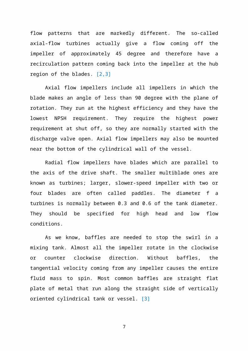
patterns that are markedly different. The so-called axial-flow turbines actually give a flow
coming off the impeller of approximately 45 degree and therefore have a recirculation pattern
coming back into the impeller at the hub region of the blades. [2,3]
Axial flow impellers include all impellers in which the blade makes an angle of less
than 90 degree with the plane of rotation. They run at the highest efficiency and they have the
lowest NPSH requirement. They require the highest power requirement at shut off, so they
are normally started with the discharge valve open. Axial flow impellers may also be
mounted near the bottom of the cylindrical wall of the vessel.
Radial flow impellers have blades which are parallel to the axis of the drive shaft. The
smaller multiblade ones are known as turbines; larger, slower-speed impeller with two or four
blades are often called paddles. The diameter f a turbines is normally between 0.3 and 0.6 of
the tank diameter. They should be specified for high head and low flow conditions.
As we know, baffles are needed to stop the swirl in a mixing tank. Almost all the
impeller rotate in the clockwise or counter clockwise direction. Without baffles, the
tangential velocity coming from any impeller causes the entire fluid mass to spin. Most
common baffles are straight flat plate of metal that run along the straight side of vertically
oriented cylindrical tank or vessel. [3]
4
For unbaffles tank, there is a tendency for a swirling flow pattern to develop
regardless of the type of impeller. A vortex is produced owing to centrifugal force acting on
the rotating liquid. However, there is a limit to the rotational speed that may be used, since
one the vortex reaches the impeller, severe air entrainment may occur. In addition, the
swirling mass of liquid often generates an oscilating surge in the tank, which coupled with the
deep vortex may create a large fluctuating force acting on the mixer shaft.
For vigorous agitation of thin suspensions, the tank is provided with baffles which flat
vertical strips set radially along the tanks wall as shown. Four baffles are almost always
adequate. A common baffle width is 1:10 to 1:12 of the tanks diameter. For Reynolds number
greater than 10,000, baffles are commonly used with turbine impellers and with on-centerline
axial-flow impellers.
In the transition region (Reynolds number, from 10 to 10,000), the width of the baffles
may be reduced, often to ½ of standard width. If the circulation pattern is satisfactory when
the tank is without baffled but a vortex creates a problem, partial length baffles may be used.
These are standard width and extend downward from the surface into about 1/3 of the liquid
volume.
In the region of laminar flow (NRe < 10), the same power is consumed by the impeller
whether baffles are present or not, and they are seldom required. The flow pattern may be
affected by the baffles but not always advantageously. When they are need, the baffles are
usually placed one or two widths radially, to allow fluid to circulate behind them and at same
time produce some axial deflection of flow.[3]
Typical flow patterns achieved using a radial flow impeller & an axial flow impeller
POWER-SPEED CHARATERISTIC
Power (W) = Torque (t) × angular speed ω (rads-1)
Torque (T) = Force recorded on spring balance × length of torque arm (r)
5
4.1 Turbulent mixing
For low viscosity liquids, the bulk flow pattern in mixing vessels with rotating
impellers is turbulent. The inertia imparted to the liquid by the rotating, impeller is sufficient
to cause the liquid to circulate throughout the vessel and return to the impeller. Turbulent
eddy diffusion takes place throughout the vessel but is a maximum in the vicinity of the
impeller. Eddy diffusion is inherently much faster than molecular diffusion and,
consequently, turbulent mixing occurs much more rapidly than laminar mixing. Ultimately
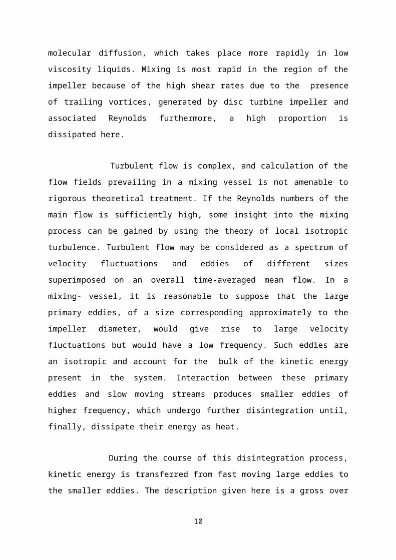
homogenization at the molecular level depends on molecular diffusion, which takes place
more rapidly in low viscosity liquids. Mixing is most rapid in the region of the impeller
because of the high shear rates due to the presence of trailing vortices, generated by disc
turbine impeller and associated Reynolds furthermore, a high proportion is dissipated here.
Turbulent flow is complex, and calculation of the flow fields prevailing in a mixing
vessel is not amenable to rigorous theoretical treatment. If the Reynolds numbers of the main
flow is sufficiently high, some insight into the mixing process can be gained by using the
theory of local isotropic turbulence. Turbulent flow may be considered as a spectrum of
velocity fluctuations and eddies of different sizes superimposed on an overall time-averaged
mean flow. In a mixing- vessel, it is reasonable to suppose that the large primary eddies, of a
size corresponding approximately to the impeller diameter, would give rise to large velocity
fluctuations but would have a low frequency. Such eddies are an isotropic and account for the
bulk of the kinetic energy present in the system. Interaction between these primary eddies and
slow moving streams produces smaller eddies of higher frequency, which undergo further
disintegration until, finally, dissipate their energy as heat.
During the course of this disintegration process, kinetic energy is transferred from fast
moving large eddies to the smaller eddies. The description given here is a gross over
simplification, but it does give a qualitative representation of the salient features of turbulent
mixing.
6
4.2 Laminar mixing
Laminar flow is usually associated with high viscosity liquids that may be either
Newtonian or non-Newtonian. The inertial forces therefore tend to die out quickly, and the
impeller of the mixer must cover a significant proportion of the cross-section of the vessel to
impart sufficient bulk motion. Because the velocity gradients close to the rotating impeller
are high, the fluid elements in that region deform and stretch. They repeatedly elongate and
become thinner each time the fluid elements pass through the high shear zone.[4]
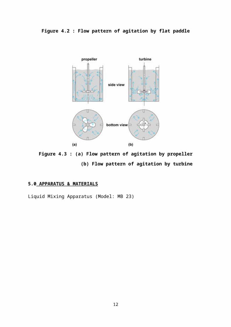
Figure 4.2 : Flow pattern of agitation by flat paddle
7
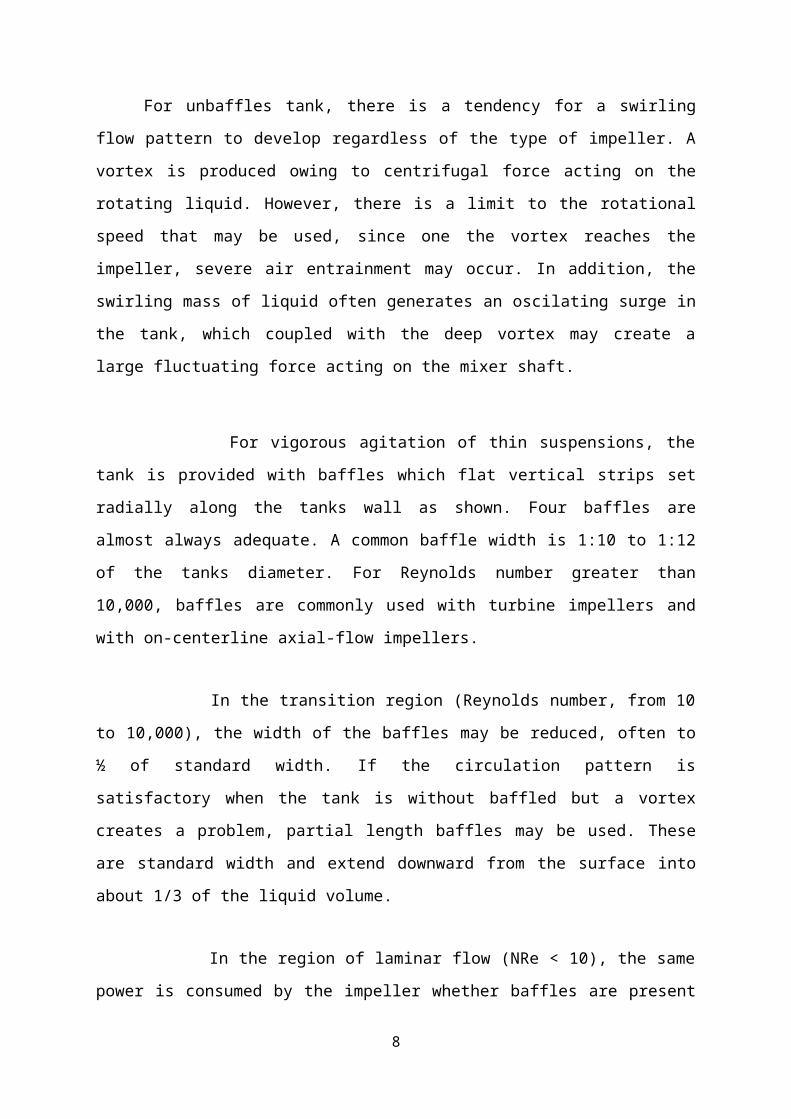
Figure 4.3 : (a) Flow pattern of agitation by propeller
(b) Flow pattern of agitation by turbine
5.0 APPARATUS & MATERIALS
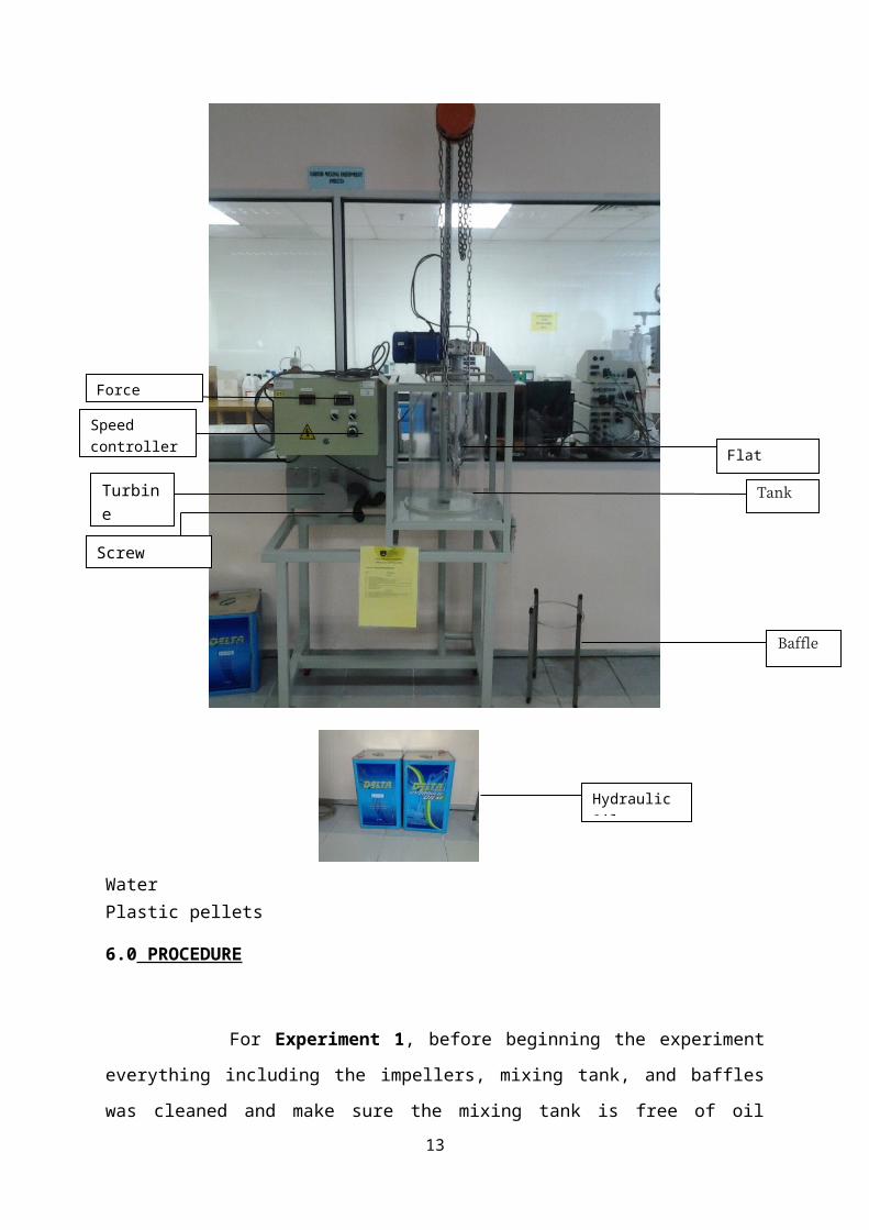
Liquid Mixing Apparatus (Model: MB 23)
WaterPlastic pellets
8
Flat paddle [Type
Tank
Baffle
Screw propeller
Force indicator
Turbine impeller
Speed controller
Hydraulic Oil
6.0 PROCEDURE
For Experiment 1, before beginning the experiment everything including the impellers,
mixing tank, and baffles was cleaned and make sure the mixing tank is free of oil stains.
Firstly, the top of the mixing tank was raised and the flat blade impeller was attached with the
base bush level with the end of the shaft. The flat blade impeller was screwed tightly to the
shaft to make sure it does not come of when the impeller turns. Water was added until it
reaches the 30cm mark. The top of the tank was lowered and fixed in position. The power
was switched on and the speed of the impeller was increased by using the speed control knob
until the swirl the water was observed. A vortex was observed and the pattern is recorded.
The procedure was repeated with each impeller (screw propeller, turbine) and again with
four baffles in position with each impeller. The observation for each impeller with and
without baffles was recorded. After the experiment 1 was over the tank was emptied by
opening the valve at the bottom of the tank.
For Experiment 2, before beginning experiment, the tank was emptied by draining all
the water out. The top of the mixing tank was raised and the flat blade impeller was attached
with the base bush level with the end of the shaft. The flat blade impeller was screwed tightly
to the shaft to make sure it does not come of when the impeller turns. Then the tank was filled
with oil until the 30cm mark. The top of the tank was lowered and fixed in position. The
torque arm clamp was adjusted until the torque meter shows 0.00. The speed was increased
by using the speed control knob to 50rpm. The reading of the torque meter was taken. The
speed was increased to 100rpm, 150rpm, 200rpm, and 250rpm and each time the reading of
the torque meter was taken. The top of the tank is raised and the baffles was fitted in the tank.
The experiment was repeated and the torque meter readings was taken.
Experiment 2 was then repeated by using the turbine. The readings was taken by using
the baffles and without the baffles.After completing the experiment the mixing tank was
emptied by opening the valve at the bottom of the tank and draining the oil out back to the
can. The whole apparatus was washed and cleaned.
9
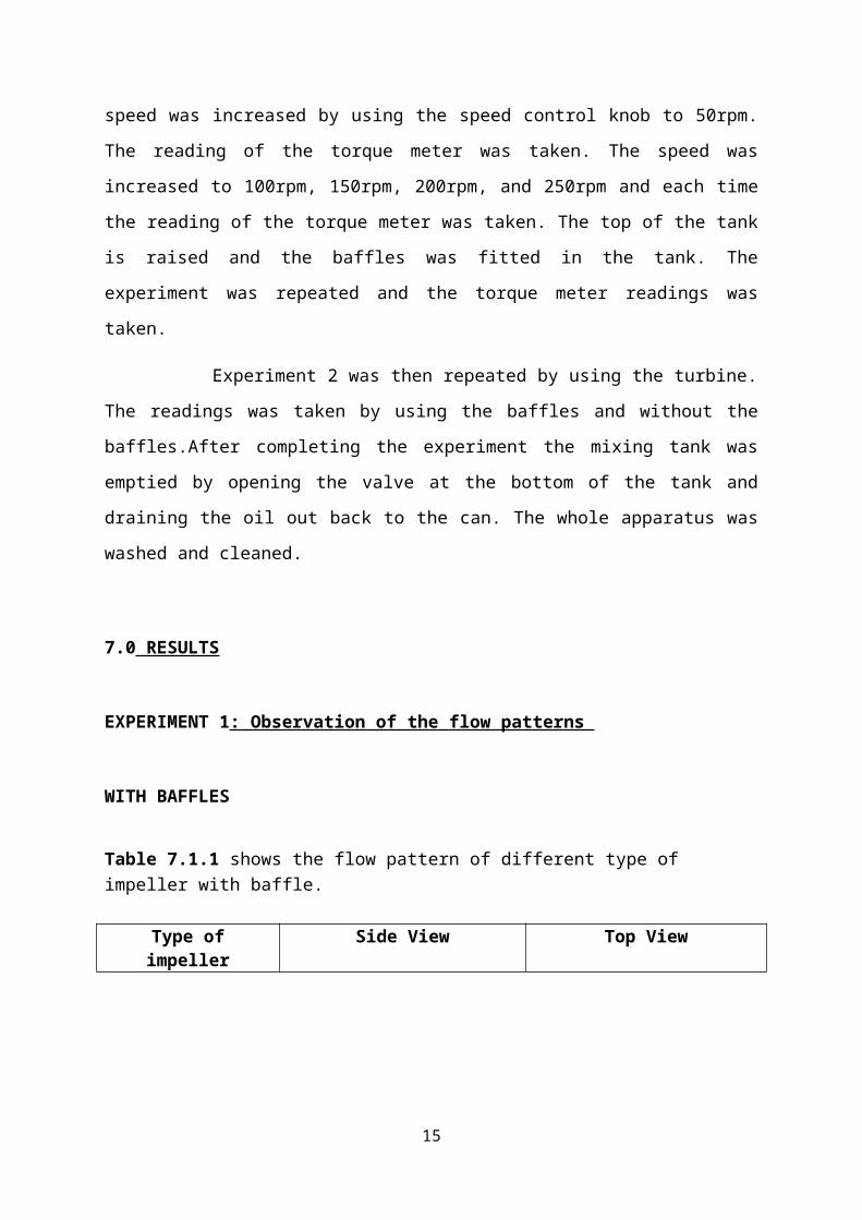
7.0 RESULTS
EXPERIMENT 1: Observation of the flow patterns
WITH BAFFLES
Table 7.1.1 shows the flow pattern of different type of impeller with baffle.
Type of impeller Side View Top View
Flat Paddle
Screw Propeller
10

Turbine Impeller
Table 7.1.1 : Flow Pattern With Baffles
WITHOUT BAFFLES
Table 7.1.2 shows the flow pattern of different type of impeller without baffle.
Type of impeller Side View Top View
Flat Paddle
11
Screw Propeller
Turbine Impeller
Table 7.1.2 : Flow Pattern Without Buffles
EXPERIMENT 2: Power consumed by a mixer
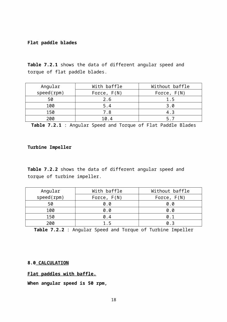
Flat paddle blades
Table 7.2.1 shows the data of different angular speed and torque of flat paddle blades.
Angular speed(rpm) With baffle Without baffleForce, F(N) Force, F(N)
50 2.6 1.5100 5.4 3.0150 7.8 4.3200 10.4 5.7
Table 7.2.1 : Angular Speed and Torque of Flat Paddle Blades
12
Turbine Impeller
Table 7.2.2 shows the data of different angular speed and torque of turbine impeller.
Angular speed(rpm) With baffle Without baffleForce, F(N) Force, F(N)
50 0.0 0.0100 0.0 0.0150 0.4 0.1200 1.5 0.3
Table 7.2.2 : Angular Speed and Torque of Turbine Impeller
8.0 CALCULATION
Flat paddles with baffle.
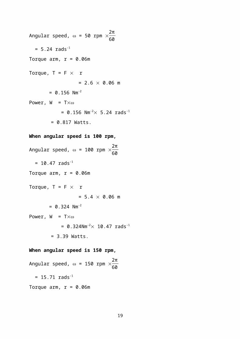
When angular speed is 50 rpm,
Angular speed, = 50 rpm 2π60
= 5.24 rads-1
Torque arm, r = 0.06m
Torque, T = F r
= 2.6 0.06 m
= 0.156 Nm-2
Power, W = T
= 0.156 Nm-2 5.24 rads-1
= 0.817 Watts.
When angular speed is 100 rpm,
Angular speed, = 100 rpm 2π60
= 10.47 rads-1
Torque arm, r = 0.06m
Torque, T = F r
13

= 5.4 0.06 m
= 0.324 Nm-2
Power, W = T
= 0.324Nm-2 10.47 rads-1
= 3.39 Watts.
When angular speed is 150 rpm,
Angular speed, = 150 rpm 2π60
= 15.71 rads-1
Torque arm, r = 0.06m
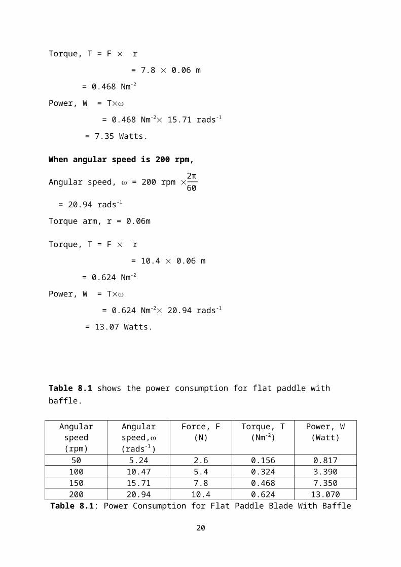
Torque, T = F r
= 7.8 0.06 m
= 0.468 Nm-2
Power, W = T
= 0.468 Nm-2 15.71 rads-1
= 7.35 Watts.
When angular speed is 200 rpm,
Angular speed, = 200 rpm 2π60
= 20.94 rads-1
Torque arm, r = 0.06m
Torque, T = F r
= 10.4 0.06 m
= 0.624 Nm-2
Power, W = T
= 0.624 Nm-2 20.94 rads-1
= 13.07 Watts.
Table 8.1 shows the power consumption for flat paddle with baffle.
14
Angular speed(rpm)
Angular speed,(rads-1 )
Force, F(N)
Torque, T(Nm-2)
Power, W(Watt)
50 5.24 2.6 0.156 0.817100 10.47 5.4 0.324 3.390150 15.71 7.8 0.468 7.350200 20.94 10.4 0.624 13.070
Table 8.1: Power Consumption for Flat Paddle Blade With Baffle
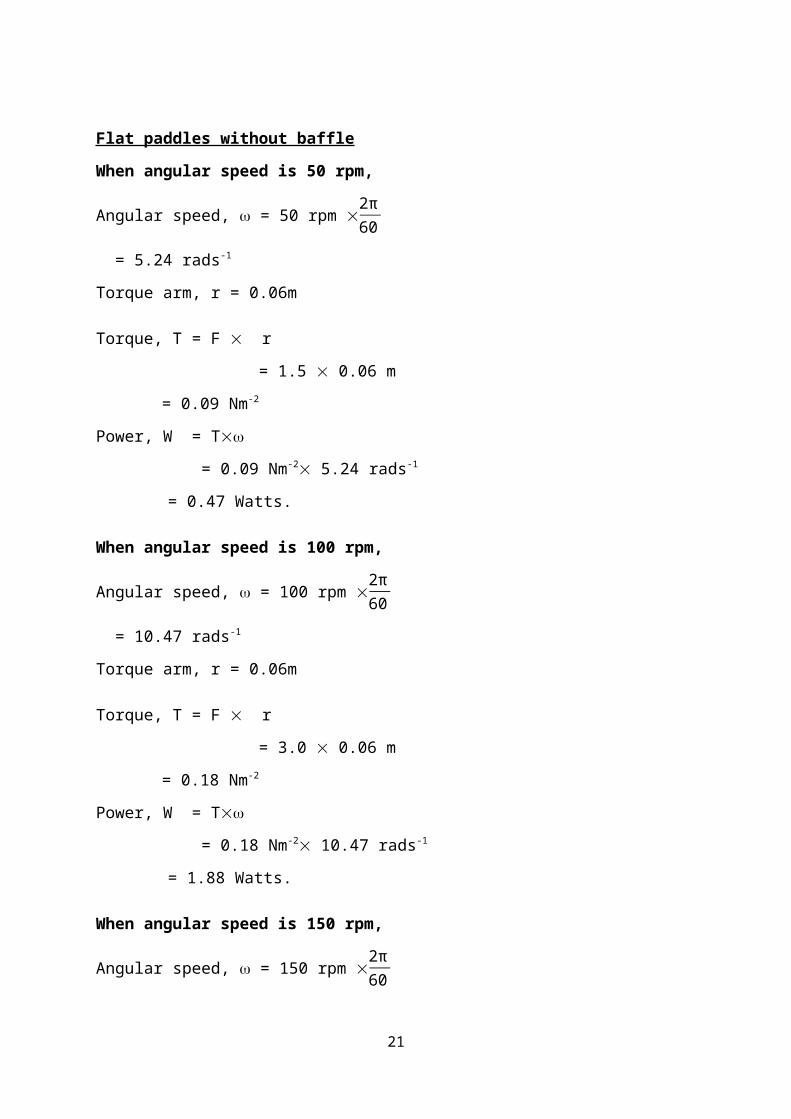
Flat paddles without baffle
When angular speed is 50 rpm,
Angular speed, = 50 rpm 2π60
= 5.24 rads-1
Torque arm, r = 0.06m
Torque, T = F r
= 1.5 0.06 m
= 0.09 Nm-2
Power, W = T
= 0.09 Nm-2 5.24 rads-1
= 0.47 Watts.
When angular speed is 100 rpm,
Angular speed, = 100 rpm 2π60
= 10.47 rads-1
Torque arm, r = 0.06m
Torque, T = F r
= 3.0 0.06 m
= 0.18 Nm-2
Power, W = T
= 0.18 Nm-2 10.47 rads-1
= 1.88 Watts.
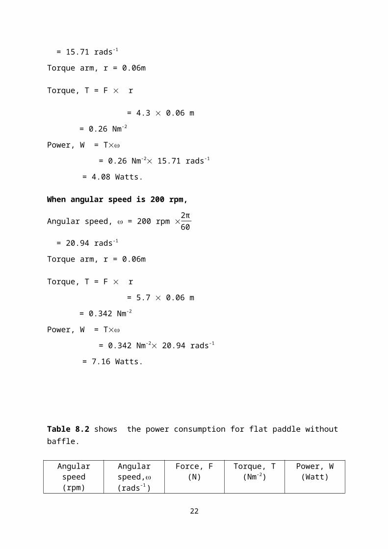
When angular speed is 150 rpm,
Angular speed, = 150 rpm 2π60
15

= 15.71 rads-1
Torque arm, r = 0.06m
Torque, T = F r
= 4.3 0.06 m
= 0.26 Nm-2
Power, W = T
= 0.26 Nm-2 15.71 rads-1
= 4.08 Watts.
When angular speed is 200 rpm,
Angular speed, = 200 rpm 2π60
= 20.94 rads-1
Torque arm, r = 0.06m
Torque, T = F r
= 5.7 0.06 m
= 0.342 Nm-2
Power, W = T
= 0.342 Nm-2 20.94 rads-1
= 7.16 Watts.
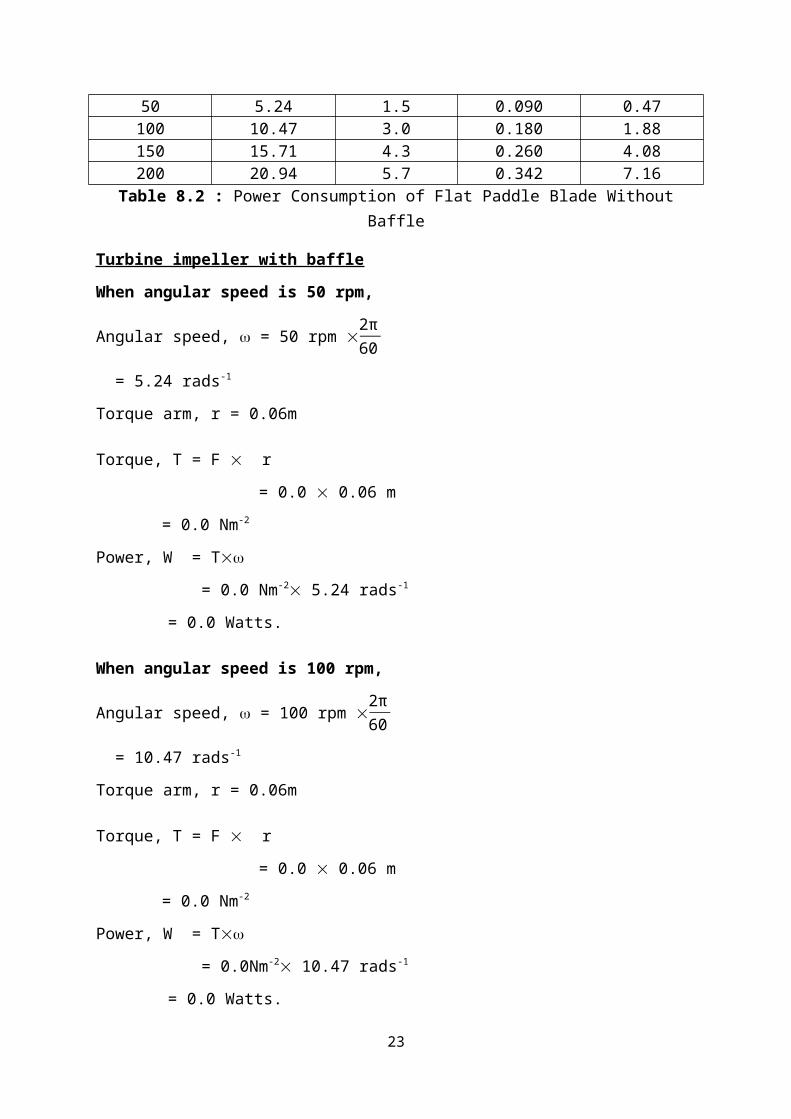
Table 8.2 shows the power consumption for flat paddle without baffle.
Angular speed(rpm)
Angular speed,(rads-1 )
Force, F(N)
Torque, T(Nm-2)
Power, W(Watt)
50 5.24 1.5 0.090 0.47100 10.47 3.0 0.180 1.88150 15.71 4.3 0.260 4.08200 20.94 5.7 0.342 7.16
Table 8.2 : Power Consumption of Flat Paddle Blade Without Baffle
Turbine impeller with baffle
When angular speed is 50 rpm,
16
Angular speed, = 50 rpm 2π60
= 5.24 rads-1
Torque arm, r = 0.06m
Torque, T = F r
= 0.0 0.06 m
= 0.0 Nm-2
Power, W = T
= 0.0 Nm-2 5.24 rads-1
= 0.0 Watts.
When angular speed is 100 rpm,
Angular speed, = 100 rpm 2π60
= 10.47 rads-1
Torque arm, r = 0.06m
Torque, T = F r
= 0.0 0.06 m
= 0.0 Nm-2
Power, W = T
= 0.0Nm-2 10.47 rads-1
= 0.0 Watts.
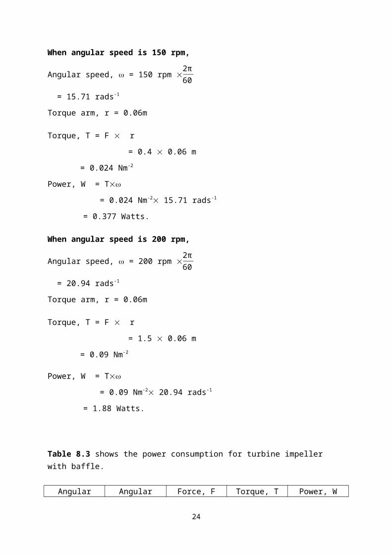
When angular speed is 150 rpm,
Angular speed, = 150 rpm 2π60
= 15.71 rads-1
Torque arm, r = 0.06m
Torque, T = F r
= 0.4 0.06 m
= 0.024 Nm-2
Power, W = T
= 0.024 Nm-2 15.71 rads-1
= 0.377 Watts.
17
When angular speed is 200 rpm,
Angular speed, = 200 rpm 2π60
= 20.94 rads-1
Torque arm, r = 0.06m
Torque, T = F r
= 1.5 0.06 m
= 0.09 Nm-2
Power, W = T
= 0.09 Nm-2 20.94 rads-1
= 1.88 Watts.
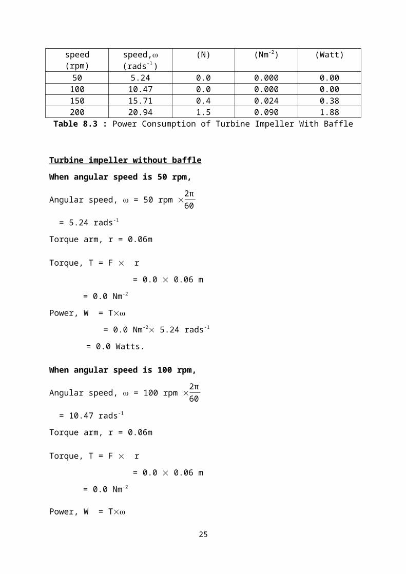
Table 8.3 shows the power consumption for turbine impeller with baffle.
Angular speed(rpm)
Angular speed,(rads-1 )
Force, F(N)
Torque, T(Nm-2)
Power, W(Watt)
50 5.24 0.0 0.000 0.00100 10.47 0.0 0.000 0.00150 15.71 0.4 0.024 0.38200 20.94 1.5 0.090 1.88
Table 8.3 : Power Consumption of Turbine Impeller With Baffle
Turbine impeller without baffle
When angular speed is 50 rpm,
Angular speed, = 50 rpm 2π60
= 5.24 rads-1
Torque arm, r = 0.06m
Torque, T = F r
= 0.0 0.06 m
= 0.0 Nm-2
Power, W = T
= 0.0 Nm-2 5.24 rads-1
= 0.0 Watts.
18
When angular speed is 100 rpm,
Angular speed, = 100 rpm 2π60
= 10.47 rads-1
Torque arm, r = 0.06m
Torque, T = F r
= 0.0 0.06 m
= 0.0 Nm-2
Power, W = T
= 0.0Nm-2 10.47 rads-1
= 0.0 Watts.
When angular speed is 150 rpm,
Angular speed, = 150 rpm 2π60
= 15.71 rads-1
Torque arm, r = 0.06m
Torque, T = F r
= 0.1 0.06 m
= 0.006 Nm-2
Power, W = T
= 0.024 Nm-2 15.71 rads-1
= 0.094 Watts.
When angular speed is 200 rpm,
Angular speed, = 200 rpm 2π60
= 20.94 rads-1
Torque arm, r = 0.06m
Torque, T = F r
= 0.3 0.06 m
= 0.018 Nm-2
Power, W = T
= 0.018 Nm-2 20.94 rads-1
19
= 0.38 Watts.
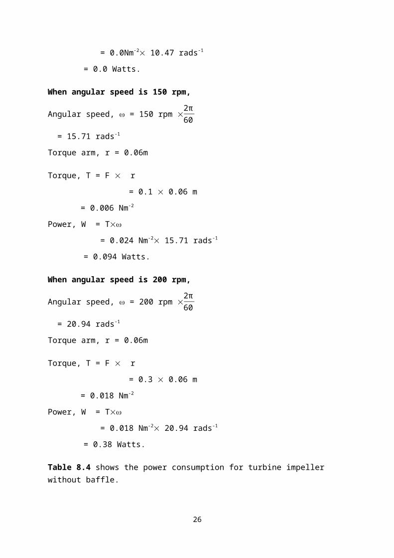
Table 8.4 shows the power consumption for turbine impeller without baffle.
Angular speed(rpm)
Angular speed,(rads-1 )
Force, F(N)
Torque, T(Nm-2)
Power, W(Watt)
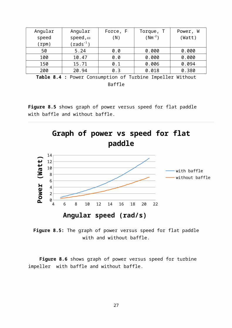
50 5.24 0.0 0.000 0.000100 10.47 0.0 0.000 0.000150 15.71 0.1 0.006 0.094200 20.94 0.3 0.018 0.380
Table 8.4 : Power Consumption of Turbine Impeller Without Baffle
Figure 8.5 shows graph of power versus speed for flat paddle with baffle and without baffle.
4 6 8 10 12 14 16 18 20 220
2
4
6
8
10
12
14
Graph of power vs speed for flat paddle
with bafflewithout baffle
Angular speed (rad/s)
Pow
er (W
att)
Figure 8.5: The graph of power versus speed for flat paddle with and without baffle.
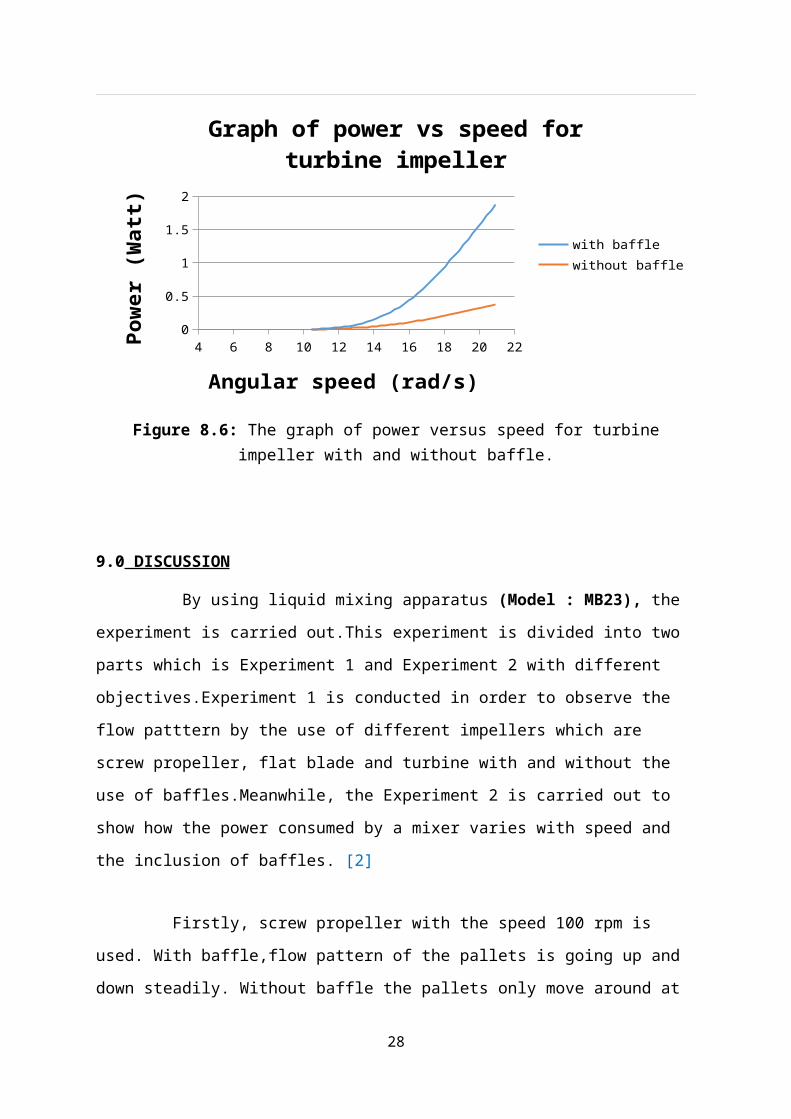
Figure 8.6 shows graph of power versus speed for turbine impeller with baffle and without baffle.
20
4 6 8 10 12 14 16 18 20 220
0.20.40.60.8
11.21.41.61.8
2
Graph of power vs speed for turbine impeller
with bafflewithout baffle
Angular speed (rad/s)
Pow
er (W
att)
Figure 8.6: The graph of power versus speed for turbine impeller with and without baffle.
9.0 DISCUSSION
By using liquid mixing apparatus (Model : MB23), the experiment is carried out.This
experiment is divided into two parts which is Experiment 1 and Experiment 2 with different
objectives.Experiment 1 is conducted in order to observe the flow patttern by the use of
different impellers which are screw propeller, flat blade and turbine with and without the use
of baffles.Meanwhile, the Experiment 2 is carried out to show how the power consumed by a
mixer varies with speed and the inclusion of baffles. [2]
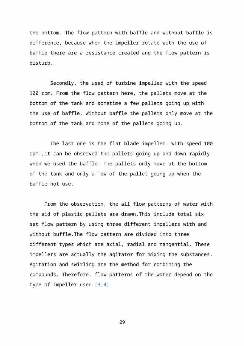
Firstly, screw propeller with the speed 100 rpm is used. With baffle,flow pattern of the
pallets is going up and down steadily. Without baffle the pallets only move around at the
bottom. The flow pattern with baffle and without baffle is difference, because when the
impeller rotate with the use of baffle there are a resistance created and the flow pattern is
disturb.
Secondly, the used of turbine impeller with the speed 100 rpm. From the flow pattern
here, the pallets move at the bottom of the tank and sometime a few pallets going up with the
use of baffle. Without baffle the pallets only move at the bottom of the tank and none of the
pallets going up.
21
The last one is the flat blade impeller. With speed 100 rpm.,it can be observed the pallets
going up and down rapidly when we used the baffle. The pallets only move at the bottom of
the tank and only a few of the pallet going up when the baffle not use.
From the observation, the all flow patterns of water with the aid of plastic pellets are
drawn.This include total six set flow pattern by using three different impellers with and
without buffle.The flow pattern are divided into three different types which are axial, radial
and tangential. These impellers are actually the agitator for mixing the substances. Agitation
and swirling are the method for combining the compounds. Therefore, flow patterns of the
water depend on the type of impeller used.[3,4]
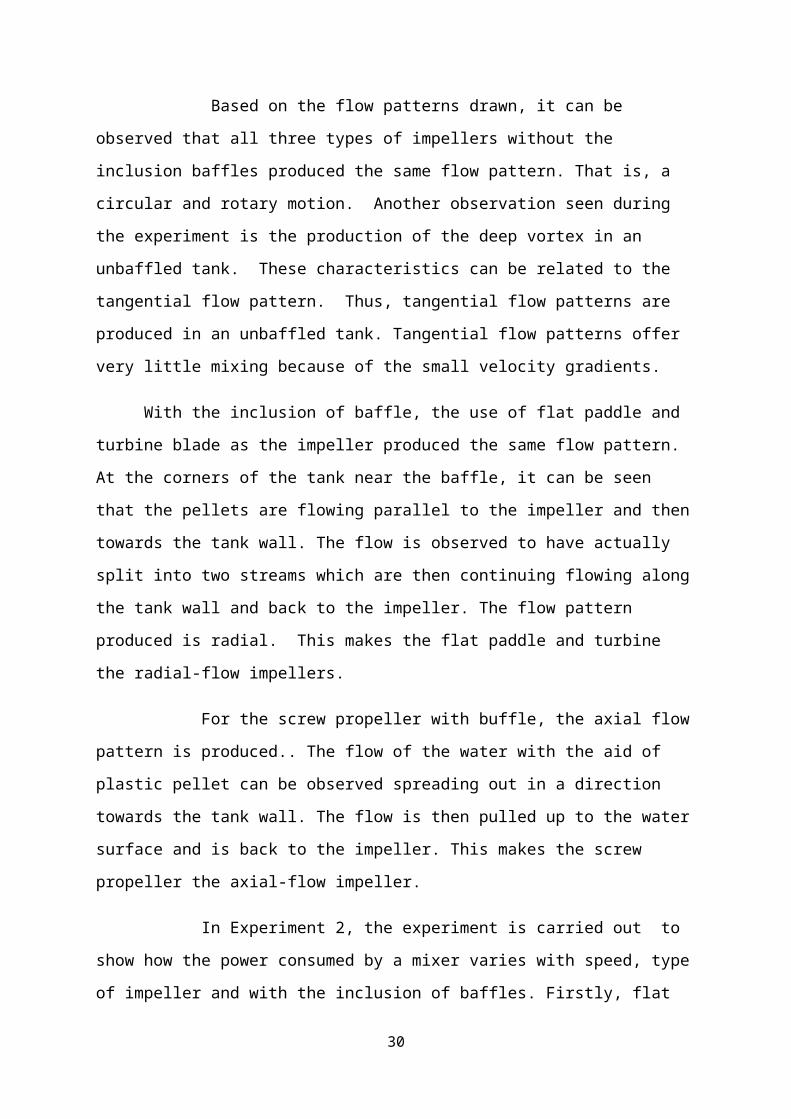
Based on the flow patterns drawn, it can be observed that all three types of impellers
without the inclusion baffles produced the same flow pattern. That is, a circular and rotary
motion. Another observation seen during the experiment is the production of the deep vortex
in an unbaffled tank. These characteristics can be related to the tangential flow pattern.
Thus, tangential flow patterns are produced in an unbaffled tank. Tangential flow patterns
offer very little mixing because of the small velocity gradients.
With the inclusion of baffle, the use of flat paddle and turbine blade as the impeller
produced the same flow pattern. At the corners of the tank near the baffle, it can be seen that
the pellets are flowing parallel to the impeller and then towards the tank wall. The flow is
observed to have actually split into two streams which are then continuing flowing along the
tank wall and back to the impeller. The flow pattern produced is radial. This makes the flat
paddle and turbine the radial-flow impellers.
For the screw propeller with buffle, the axial flow pattern is produced.. The flow of the
water with the aid of plastic pellet can be observed spreading out in a direction towards the
tank wall. The flow is then pulled up to the water surface and is back to the impeller. This
makes the screw propeller the axial-flow impeller.
In Experiment 2, the experiment is carried out to show how the power consumed by a
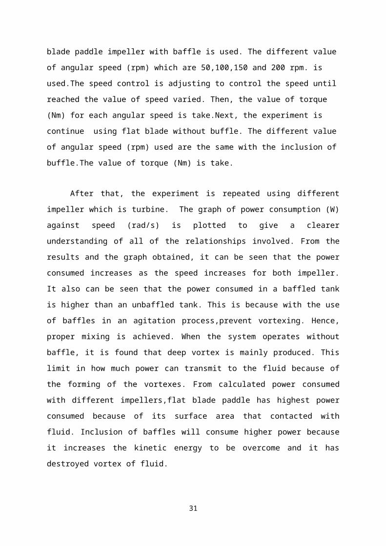
mixer varies with speed, type of impeller and with the inclusion of baffles. Firstly, flat blade
paddle impeller with baffle is used. The different value of angular speed (rpm) which are
50,100,150 and 200 rpm. is used.The speed control is adjusting to control the speed until
22
reached the value of speed varied. Then, the value of torque (Nm) for each angular speed is
take.Next, the experiment is continue using flat blade without buffle. The different value of
angular speed (rpm) used are the same with the inclusion of buffle.The value of torque (Nm)
is take.
After that, the experiment is repeated using different impeller which is turbine. The
graph of power consumption (W) against speed (rad/s) is plotted to give a clearer
understanding of all of the relationships involved. From the results and the graph obtained, it
can be seen that the power consumed increases as the speed increases for both impeller. It
also can be seen that the power consumed in a baffled tank is higher than an unbaffled tank.
This is because with the use of baffles in an agitation process,prevent vortexing. Hence,
proper mixing is achieved. When the system operates without baffle, it is found that deep
vortex is mainly produced. This limit in how much power can transmit to the fluid because of
the forming of the vortexes. From calculated power consumed with different impellers,flat
blade paddle has highest power consumed because of its surface area that contacted with
fluid. Inclusion of baffles will consume higher power because it increases the kinetic energy
to be overcome and it has destroyed vortex of fluid.
By comparing both graph with buffles, turbine consumed less power compare to flat
blades.The theory said turbine should consumed less power than flat blades.So based on the
both graph obtained, it can be said that the experiment follow the theory stated. Then the
experiment is repeated without using baffles. The graph above shown the flat paddle is
consuming more power than the turbine. So, it is true with the theory that flat paddles blade
should consume more power. So, this experiment is to be said successfully done.
Eventhough the experiment are to be said succesfull but there are silly mistakes happened
also during the experiment.There is some inaccuracy happened due to errors occurred.
Firstly, the tank is not cleaned thoroughly after conducting experiment. An unclean tank
could affect the reading of the force because of the mixing of the substances: oil and water.
Other than that, when the scale of the tank is not viewed from a perpendicular position, it can
cause parallax error during the measuring and filling the tank with water and oil. Also, only
one type of color of plastic pellets are used to detect the flow patterns. The use of only the
same color of plastic pellet could make it harder for the flow patterns to be detected. [2,4]
23
10.0 CONCLUSION
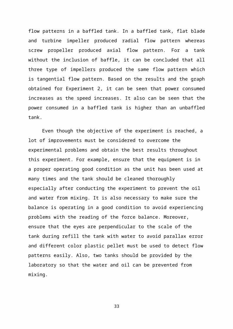
From the observation in Experiment 1, it can be concluded that different impellers
produce different type of flow patterns in a baffled tank. In a baffled tank, flat blade and
turbine impeller produced radial flow pattern whereas screw propeller produced axial flow
pattern. For a tank without the inclusion of baffle, it can be concluded that all three type of
impellers produced the same flow pattern which is tangential flow pattern. Based on the
results and the graph obtained for Experiment 2, it can be seen that power consumed
increases as the speed increases. It also can be seen that the power consumed in a baffled tank
is higher than an unbaffled tank.
Even though the objective of the experiment is reached, a lot of improvements must
be considered to overcome the experimental problems and obtain the best results throughout
this experiment. For example, ensure that the equipment is in a proper operating good
condition as the unit has been used at many times and the tank should be cleaned thoroughly
especially after conducting the experiment to prevent the oil and water from mixing. It is also
necessary to make sure the balance is operating in a good condition to avoid experiencing
problems with the reading of the force balance. Moreover, ensure that the eyes are
perpendicular to the scale of the tank during refill the tank with water to avoid parallax error
and different color plastic pellet must be used to detect flow patterns easily. Also, two tanks
should be provided by the laboratory so that the water and oil can be prevented from mixing.
11.0 RECOMMENDATION
Due to the experiment that has been done, there are few recommendations that
should be considered to get the best results needed throughout in this experiment. First and
the foremost, ensure that the equipment is in a proper operating good condition. It is
suggested to repair and always do some maintenance for this equipment when the unit has
been used at many times.
Since this experiment should be done with water source and coagulant or oil as a
fluid, the tank should be cleaned thoroughly especially after conducting the experiment with
oil. This is because to prevent the high concentration of coagulant or oil to be attached the
24
wall of the tank. This is also to prevent the oil and water from mixing. Therefore, the tank can
be used again when conducting the next experiment.
Furthermore, it is much better to suggest that two tanks should be provided by the
laboratory. One of them is for water and the remaining one for coagulant or oil. This is to
ensure that the water and oil can be prevented from mixing. The mixture between water and
oil can be happened if only one tank provided and used the same tank to conduct the
experiment. This will affect the data as well as inaccurate readings when conducting this
experiment.
Moreover, it is necessary to make sure the balance is operating in a good condition. If
the balance is not operating very well, it will affect the reading for the force balance
regarding to each speed of impellers. It is not the right way to measure the force by operating
the tension spring manually, it is much better to use the tension spring that operated by
computer itself. Indirectly, the accurate readings can be obtained as the best results needed.
Last but not least, ensure that the eyes must be perpendicular to the scale of the tank
during refill the tank with water to avoid parallax error. Besides that, always make sure that
the water does not spill over the side of the tank by increasing the speed too much. In
addition, several different colors of plastic pallets can be used, so the flow pattern can be
detected easily.
12.0 REFERENCES
1.Douglas J.F Fluid mechanics fourth edition, Prentice Hall 2004
2.Perry’s Chemical Engineer Handbook, 8th Edition, Don W. Green, Robert H. Perry,18-6 –
18-13.
3.Frank M.W, Fluid Mechanics ninth edition, McGraw-Hill.2005
4.www.sciencedirect.com
APPENDICES
25
APPARATUS USED FOR BOTH EXPERIMENT
a)Impellers used and baffle. b)Set up of mixing tank
c)Main board with switch and torque meter. d)Flow pattern without baffle.
e)Flow pattern with baffle. f)mixing of oil.
SAMPLE CALCULATION
Flat paddles with baffle.
When angular speed is 50 rpm,
26
Angular speed, = 50 rpm 2π60
= 5.24 rads-1
Torque arm, r = 0.06m
Torque, T = F r
= 2.6 0.06 m
= 0.156 Nm-2
Power, W = T
= 0.156 Nm-2 5.24 rads-1
= 0.817 Watts.
When angular speed is 100 rpm,
Angular speed, = 100 rpm 2π60
= 10.47 rads-1
Torque arm, r = 0.06m
Torque, T = F r
= 5.4 0.06 m
= 0.324 Nm-2
Power, W = T
= 0.324Nm-2 10.47 rads-1
= 3.39 Watts.
When angular speed is 150 rpm,
Angular speed, = 150 rpm 2π60
= 15.71 rads-1
Torque arm, r = 0.06m
Torque, T = F r
= 7.8 0.06 m
= 0.468 Nm-2
Power, W = T
= 0.468 Nm-2 15.71 rads-1
27
= 7.35 Watts.
When angular speed is 200 rpm,
Angular speed, = 200 rpm 2π60
= 20.94 rads-1
Torque arm, r = 0.06m
Torque, T = F r
= 10.4 0.06 m
= 0.624 Nm-2
Power, W = T
= 0.624 Nm-2 20.94 rads-1
= 13.07 Watts.
Table 8.1 shows the power consumption for flat paddle with baffle.
Angular speed(rpm)
Angular speed,(rads-1 )
Force, F(N)
Torque, T(Nm-2)
Power, W(Watt)
50 5.24 2.6 0.156 0.817100 10.47 5.4 0.324 3.390150 15.71 7.8 0.468 7.350200 20.94 10.4 0.624 13.070
Table 8.1: Power Consumption for Flat Paddle Blade With Baffle
Flat paddles without baffle
When angular speed is 50 rpm,
Angular speed, = 50 rpm 2π60
= 5.24 rads-1
Torque arm, r = 0.06m
Torque, T = F r
= 1.5 0.06 m
= 0.09 Nm-2
Power, W = T
28
= 0.09 Nm-2 5.24 rads-1
= 0.47 Watts.
When angular speed is 100 rpm,
Angular speed, = 100 rpm 2π60
= 10.47 rads-1
Torque arm, r = 0.06m
Torque, T = F r
= 3.0 0.06 m
= 0.18 Nm-2
Power, W = T
= 0.18 Nm-2 10.47 rads-1
= 1.88 Watts.
When angular speed is 150 rpm,
Angular speed, = 150 rpm 2π60
= 15.71 rads-1
Torque arm, r = 0.06m
Torque, T = F r
= 4.3 0.06 m
= 0.26 Nm-2
Power, W = T
= 0.26 Nm-2 15.71 rads-1
= 4.08 Watts.
When angular speed is 200 rpm,
Angular speed, = 200 rpm 2π60
= 20.94 rads-1
Torque arm, r = 0.06m
Torque, T = F r
= 5.7 0.06 m
29
= 0.342 Nm-2
Power, W = T
= 0.342 Nm-2 20.94 rads-1
= 7.16 Watts.
Table 8.2 shows the power consumption for flat paddle without baffle.
Angular speed(rpm)
Angular speed,(rads-1 )
Force, F(N)
Torque, T(Nm-2)
Power, W(Watt)
50 5.24 1.5 0.090 0.47100 10.47 3.0 0.180 1.88150 15.71 4.3 0.260 4.08200 20.94 5.7 0.342 7.16
Table 8.2 : Power Consumption of Flat Paddle Blade Without Baffle
Turbine impeller with baffle
When angular speed is 50 rpm,
Angular speed, = 50 rpm 2π60
= 5.24 rads-1
Torque arm, r = 0.06m
Torque, T = F r
= 0.0 0.06 m
= 0.0 Nm-2
Power, W = T
= 0.0 Nm-2 5.24 rads-1
= 0.0 Watts.
When angular speed is 100 rpm,
Angular speed, = 100 rpm 2π60
= 10.47 rads-1
Torque arm, r = 0.06m
Torque, T = F r
30
= 0.0 0.06 m
= 0.0 Nm-2
Power, W = T
= 0.0Nm-2 10.47 rads-1
= 0.0 Watts.
When angular speed is 150 rpm,
Angular speed, = 150 rpm 2π60
= 15.71 rads-1
Torque arm, r = 0.06m
Torque, T = F r
= 0.4 0.06 m
= 0.024 Nm-2
Power, W = T
= 0.024 Nm-2 15.71 rads-1
= 0.377 Watts.
When angular speed is 200 rpm,
Angular speed, = 200 rpm 2π60
= 20.94 rads-1
Torque arm, r = 0.06m
Torque, T = F r
= 1.5 0.06 m
= 0.09 Nm-2
Power, W = T
= 0.09 Nm-2 20.94 rads-1
= 1.88 Watts.
Table 8.3 shows the power consumption for turbine impeller with baffle.
Angular speed(rpm)
Angular speed,(rads-1 )
Force, F(N)
Torque, T(Nm-2)
Power, W(Watt)
31

50 5.24 0.0 0.000 0.00100 10.47 0.0 0.000 0.00150 15.71 0.4 0.024 0.38200 20.94 1.5 0.090 1.88
Table 8.3 : Power Consumption of Turbine Impeller With Baffle
Turbine impeller without baffle
When angular speed is 50 rpm,
Angular speed, = 50 rpm 2π60
= 5.24 rads-1
Torque arm, r = 0.06m
Torque, T = F r
= 0.0 0.06 m
= 0.0 Nm-2
Power, W = T
= 0.0 Nm-2 5.24 rads-1
= 0.0 Watts.
When angular speed is 100 rpm,
Angular speed, = 100 rpm 2π60
= 10.47 rads-1
Torque arm, r = 0.06m
Torque, T = F r
= 0.0 0.06 m
= 0.0 Nm-2
Power, W = T
= 0.0Nm-2 10.47 rads-1
= 0.0 Watts.
When angular speed is 150 rpm,
Angular speed, = 150 rpm 2π60
= 15.71 rads-1
32
Torque arm, r = 0.06m
Torque, T = F r
= 0.1 0.06 m
= 0.006 Nm-2
Power, W = T
= 0.024 Nm-2 15.71 rads-1
= 0.094 Watts.
When angular speed is 200 rpm,
Angular speed, = 200 rpm 2π60
= 20.94 rads-1
Torque arm, r = 0.06m
Torque, T = F r
= 0.3 0.06 m
= 0.018 Nm-2
Power, W = T
= 0.018 Nm-2 20.94 rads-1
= 0.38 Watts.
Table 8.4 shows the power consumption for turbine impeller without baffle.
Angular speed(rpm)
Angular speed,(rads-1 )
Force, F(N)
Torque, T(Nm-2)
Power, W(Watt)
50 5.24 0.0 0.000 0.000100 10.47 0.0 0.000 0.000150 15.71 0.1 0.006 0.094200 20.94 0.3 0.018 0.380
Table 8.4 : Power Consumption of Turbine Impeller Without Baffle
GRAPH
33
4 6 8 10 12 14 16 18 20 220
2
4
6
8
10
12
14
Graph of power vs speed for flat paddle
with bafflewithout baffle
Angular speed (rad/s)
Pow
er (W
att)
Figure 8.5: The graph of power versus speed for flat paddle with and without baffle.
4 6 8 10 12 14 16 18 20 220
0.20.40.60.8
11.21.41.61.8
2
Graph of power vs speed for turbine impeller
with bafflewithout baffle
Angular speed (rad/s)
Pow
er (W
att)
Figure 8.6: The graph of power versus speed for turbine impeller with and without baffle.
34
35