fluid power introduction booklet
DESCRIPTION
Introduction to ST20003TRANSCRIPT

1
FLUID POWER
Introduction
So what is fluid power? In simple terms it is the controlled transmission of energy by means of a fluid either oil (hydraulics) or air (pneumatics). Power can be transmitted and movement controlled in a variety of ways: Mechanical – clutches, gears, levers etc. Electrical – motors, switchgear, generators, etc Hydraulic – valves, pumps, motors, cylinders, etc Pneumatic – valves, compressors, etc Applications of pneumatics and hydraulics Fluid power - oil hydraulics and pneumatics - is universally used throughout industry to control a wide range of industrial machinery and equipment. Hydraulic systems operate with pressurised liquids, whilst pneumatics use compressed air. A few examples are shown below. Earth moving machines such as excavators. (Hydraulics) Winches on cranes and boats. (Hydraulics) Rams for extrusion presses. (Hydraulics) Automated production lines. (Pneumatic and Hydraulic) Aeroplane controls. (Hydraulic). Automated assembly units. (Pneumatic and Hydraulic) Robots. (Pneumatic and Hydraulic) Machine tools (Hydraulic)
Blaise Pascal 1623 – 1662 was a very
influential French mathematician and
philosopher who contributed too many areas of
mathematics.
Pascal's law or Pascal's principle states that
for all points at the same absolute height in a
connected body of an incompressible fluid at
rest, the fluid pressure is the same, even if
additional pressure is applied on the fluid at
some place.

2
Hydraulic power is usually used where precise control of large forces is required (such as aircraft rudder control) Pneumatic power is used where rapid movement is required involving light forces (rapid assembly of electrical components).
The Benefits of Fluid Power
Safety in industrial applications is paramount, hydraulic and pneumatic systems figure prominently in steering and braking systems. Hydraulic control systems and landing gear help to keep aircraft safe during take- off and landing and during flight. Pneumatic and hydraulic systems are used throughout the mining and tunnelling industry. Pneumatic and hydraulic systems offer reliability and precision, both important factors as consumers and manufacturers seek higher levels of quality. Handling, clamping and robotic welding systems can help to achieve higher output and productivity in the manufacturing sector, whilst in the plastics industry, the combination of hydraulics, pneumatics and electronics (mechatronics) means that fully automated production can be achieved with a high degree of precision and quality. Pneumatic systems are clean, essential where contamination of a product could cause serious consequences such as in the pharmaceutical industry. Well designed pneumatic and hydraulic systems can help organisations be more competitive and reduce costs, by the use of equipment such as fork lift trucks, excavators, and automated production equipment, where one man can literally move a mountain of earth which in the past would have taken a gang of workers. The Basics of a fluid power system
A typical fluid power system may include the following components: Pump / air compressor – to convert mechanical power to fluid power Cylinder / motor – to convert fluid power to linear or rotary mechanical power Valves – to control direction and flow Filters / regulators to condition the fluid medium Seals to contain the fluid Accumulators / reservoirs – to store the fluid Instruments such as pressure switches, flow meters, transducers – to monitor performance of the system

3
Hydraulic pumps
The pump is the heart of a hydraulic system. The simple system shown below demonstrates how
a pump sucks oil from a tank and pushes it through a DCV to the cylinder and the piston is
forced down. The oil expelled from the bottom of the cylinder is guided back to the tank by the
valve. If the valve is operated the piston in the cylinder moves up. At all times the flow of oil and
the energy required to move the piston is supplied by the pump.
Pumps are divided into two categories:
Non positive displacement types and Positive displacement types
Non positive displacement pumps
There are two main types in this category, they are CENTRIFUGAL and AXIAL
In both cases a continuous flow is produced by a rotating impeller. There is no positive seal
between the inlet and outlet and if the impeller was stopped, flow could be forced through it.
When the pressure rises on the outlet, flow may slip back from the outlet to the inlet and the
output flow rate is reduced.
4
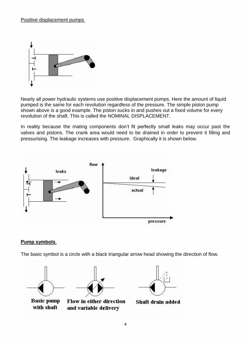
Positive displacement pumps
Nearly all power hydraulic systems use positive displacement pumps. Here the amount of liquid pumped is the same for each revolution regardless of the pressure. The simple piston pump shown above is a good example. The piston sucks in and pushes out a fixed volume for every revolution of the shaft. This is called the NOMINAL DISPLACEMENT.
In reality because the mating components don’t fit perfectly small leaks may occur past the
valves and pistons. The crank area would need to be drained in order to prevent it filling and
pressurising. The leakage increases with pressure. Graphically it is shown below.
Pump symbols
The basic symbol is a circle with a black triangular arrow head showing the direction of flow.
5
Pump protection
Positive displacement pumps should in theory deliver the same volume of fluid no matter how
much the outlet is restricted. If the flow from the pump becomes blocked, the pressure will rise
and could damage the pump. Shaft seals could blow out or the pump case might crack. The first
line of protection is likely to be a pressure relief valve on the pump outlet. Another method might
be the use of a pressure switch on the pump outlet to switch off the motor when a pre
determined pressure is reached. Some pumps (variable geometry) are designed so that the build
up in pressure on the outlet changes the geometry of the pump and makes it pump less oil.
Types of hydraulic pumps
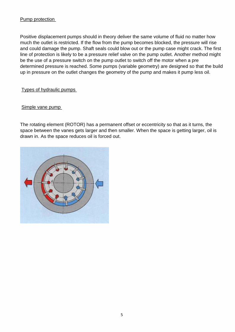
Simple vane pump
The rotating element (ROTOR) has a permanent offset or eccentricity so that as it turns, the
space between the vanes gets larger and then smaller. When the space is getting larger, oil is
drawn in. As the space reduces oil is forced out.

6
Variable delivery vane pump
The principles are the same but adjusting items (1) and (3) on the diagram can change the
eccentricity of the ring relative to the rotor. This enables the quantity of oil being pumped to be
set to a required value. The pump can be designed so that as the pressure increases beyond a
set limit, it forces the ring to a concentric position and reduces the flow to zero thus protecting the
pump.
Pumps with variable delivery such as the eccentric ring vane pump, may be designed to reduce
their flow as the pressure rises.

7
Radial piston pump
There are many designs for radial piston pumps. The design shown above has three pistons (3)
arranged around an eccentric cam (2). The cam is part of the main shaft (1) and when it rotates
the pistons are made to reciprocate inside cylinders (4) which lay on a radial line. When the
piston moves inwards the space in the cylinder fills with oil through the suction valve (7) and the
suction port (s). When the piston moves outwards, the oil is trapped inside and forced out to the
pressure port (p).
Gear pump
These are very common and have only two moving parts. The input shaft (3) carries the driving
gear (7) that turns the idler gear (8). Oil from the suction port is carried around in the space
between the gears and at the pressure port the gears mesh and form a barrier so the oil is forced
out.
8
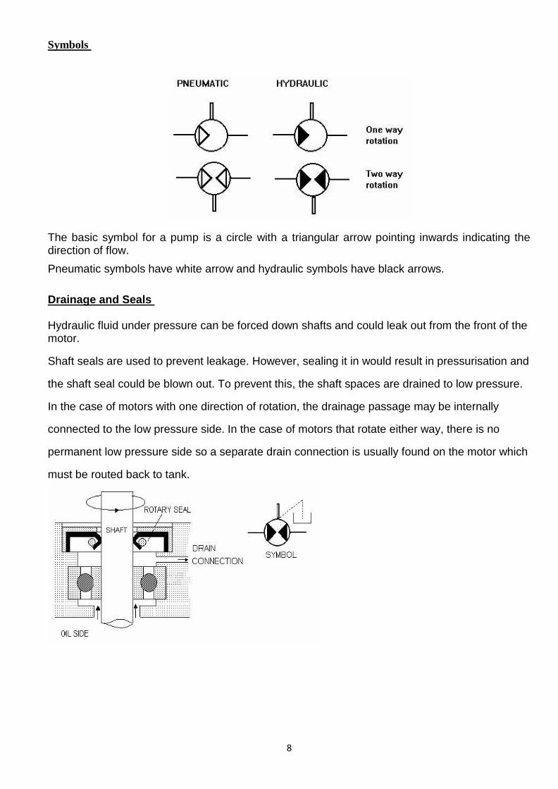
Symbols
The basic symbol for a pump is a circle with a triangular arrow pointing inwards indicating the direction of flow.
Pneumatic symbols have white arrow and hydraulic symbols have black arrows.
Drainage and Seals Hydraulic fluid under pressure can be forced down shafts and could leak out from the front of the motor.
Shaft seals are used to prevent leakage. However, sealing it in would result in pressurisation and
the shaft seal could be blown out. To prevent this, the shaft spaces are drained to low pressure.
In the case of motors with one direction of rotation, the drainage passage may be internally
connected to the low pressure side. In the case of motors that rotate either way, there is no
permanent low pressure side so a separate drain connection is usually found on the motor which
must be routed back to tank.

9
Motor types
Hydraulic motors convert hydraulic energy into mechanical energy. They are classified according to the type of internal elements that are directly actuated by the flow of fluid. Hydraulic motors are very similar in construction to hydraulic pumps. In fact many pumps may be used as motors without major modification. Like hydraulic pumps most hydraulic motors are classified as gear, vane, piston
The purpose of a rotary motor is to convert fluid power into shaft power by forcing the shaft to rotate. Pressure is converted into torque and flow rate is converted into speed. In other words, the faster you push the fluid through the motor, the faster it goes and the harder it is to turn the shaft, the higher the pressure needed to make it go round.
Rotary motors are generally rated in terms of DISPLACEMENT or TORQUE. They may be fixed displacement motors or variable displacement motors. Fixed displacement motors normally have constant torque, the speed being varied by altering the flow to the motor, whilst variable displacement motors have variable torque and speed.

10
Gear motors
Fluid is pumped into the motor inlet (P) where it has two courses to follow around the outside in the space between the teeth to the exit at (T).
Like the gear pump the gears in a gear motor are closely fitted in the housing end and, for this reason, flow of fluid through the motor from the inlet to the outlet can occur only when the gears rotate. In the gear motor fluid drives both gears but only one gear is coupled to the output shaft to supply rotary mechanical motion.
Gear motors are of the fixed displacement type, meaning that the output shaft speed varies only when the flow rate through the motor changes. These motors are generally twin directional, the motor being reversed by changing the direction of the fluid through the motor .
Vane motors
Flow from the pump enters the inlet, forces the rotor and vanes to rotate and passes out through the outlet. Rotation of the rotor causes the output shaft to rotate.
Since no centrifugal force exists until the rotor begins to rotate some method must be provided to initially hold the vanes against the casing contour. Springs are often used for this purpose. Springs are usually unnecessary in vane pumps because the drive shaft in these units initially supplies the centrifugal force to assure vane-to-casing contact.
Vane motors rotate in either direction but they do so only when the flow rate through the motor is reversed.
11
Cylinders
Cylinders are linear actuators which convert fluid power into mechanical power. They are also known as JACKS or RAMS.
Hydraulic cylinders are used at high pressures and produce large forces and precise movement. For this reason they are constructed of strong materials such as steel and designed to withstand large forces.
Because gas is an expansive substance, it is dangerous to use pneumatic cylinders at high pressures so they are limited to about 10 bar pressure. Consequently they are constructed from lighter materials such as aluminium and brass. Because gas is a compressible substance, the motion of a pneumatic cylinder is hard to control precisely. The basic theory for hydraulic and pneumatic cylinders is otherwise the same.
Force
Fluid pushes against the face of the piston and produces a force. The force produced is given by the formula:
F = p A
Where:
p is the pressure in ( N/m2
)
A is the area the pressure acts on (m2
)
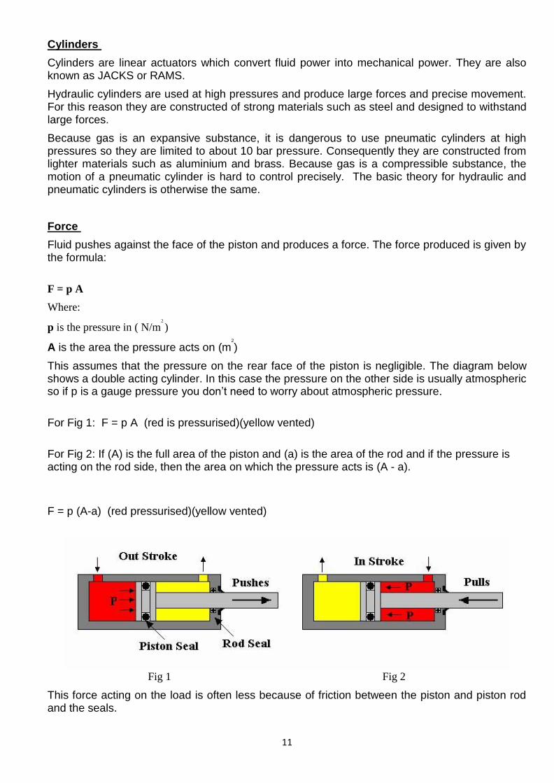
This assumes that the pressure on the rear face of the piston is negligible. The diagram below shows a double acting cylinder. In this case the pressure on the other side is usually atmospheric so if p is a gauge pressure you don’t need to worry about atmospheric pressure.
For Fig 1: F = p A (red is pressurised)(yellow vented)
For Fig 2: If (A) is the full area of the piston and (a) is the area of the rod and if the pressure is acting on the rod side, then the area on which the pressure acts is (A - a).
F = p (A-a) (red pressurised)(yellow vented)
Fig 1 Fig 2
This force acting on the load is often less because of friction between the piston and piston rod and the seals.

12
Examples In figure 1 An operating pressure of 20 Bar is acting on a piston of diameter of 30mm. Calculate the generated force (F) Solution:
kNFNF
md
A
APFA
FpgU
413.16.1413107068.01020
107068.04
)030(.
4
sin
35
2322
kNF 413.1
In figure 2 An operating pressure of 20 Bar is acting on a piston diameter of 30mm, the piston rod diameter is 10mm Calculate: a) Force acting on the rod side of the piston b) Outlet pressure Solution a)
35
232
3
10628.01020
10628.04
)010.0(107068.0
F
maA
aApF
NF 1256
Solution b)
)(/203.1777023107068.0
1256 2
3PamN
A
Fp
barp 78.17

13
Speed
The speed of the piston and rod depends upon the flow rate of fluid. The volume per second entering the cylinder must be the change in volume per second inside.
Thus vAQ 0
Where 0
Q = Volumetric flow (m3/s)
A = cross sectional area (m2)
v = Velocity (m/s)
For the rod side:
vaAQ 0
Example
Calculate the volume flow rate of a hydraulic fluid required to move a
piston of diameter 300mm, a distance of 400mm in 20 seconds.
vAQ 0
Find V sm
s
m
t
dv /02.0
20
4.0
Find A
222
0706.04
3.0
4m
dA
Therefore
s
lt
s
m
s
mQ 41.1100000141.002.00706.0
330

14
Example 2
If a hydraulic ram of diameter 280mm, moves 450mm in 30 seconds.
Calculate the volume flow rate.
vAQ 0
Find V
sm
s
m
t
dv /015.0
30
45.0
Find A
222
0615.04
28.0
4m
dA
Therefore
s
lt
s
mQ 9335.010000009225.0015.00615.0
30
For air cylinders you must remember that Q is the volume of compressed air and as this changes with pressure then any variation in pressure will cause a variation in velocity.

15
Power
Mechanical power is defined as:
vFP
Where P = Power (W) 1 w = 1 J/s
F = Force (N) 1Kg (m / s2)
v = Velocity (m/s)
Example method 1
A hydraulic press is operated by a pressure of 10 Bar acting on a ram with a face diameter of 280mm. If
the ram moves 450mm in 30 seconds, calculate the power in Watts.
vFP
find ApF
51010F 4
280.0 2
N61575 kN57.61
Find V sm
s
m
t
dv /015.0
30
45.0
Therefore
kWs
kNmvFP 92355.0015.057.61
WP 55.923

16
Example method 2
pQP 0
vAQ0
s
m32
000923.0015.04
280.0
WpQP 9231010000923.0 50
This makes it easy to calculate the power of a cylinder. Remember that the fluid power supplied will be more than the mechanical power output because of friction loses between the sliding parts of the cylinder.

17
Single acting cylinders
Single acting cylinders are only powered in one direction and therefore need an external force to return it such as the weight of a car on a car jack or a spring as shown below. There is no hydraulic fluid present on the low pressure side.
Double piston rod cylinder
The basic design is shown below. This design allows equal force and speed in either direction. Examples can be found in robotic mechanisms were the piston rods are clamped at each end allowing the body to move.
Telescopic cylinders
The sections of these cylinders telescope as can be seen in the diagram below allowing longer strokes in confined areas. Typical arrangements can have from between 2 to 5 stages and can be found in lifts, tipping vehicles, lifting platforms and other commercial vehicle applications.

18
Seals and bearings
The diagram below shows a typical double acting cylinder. The main seals used are:
A) Piston seals to prevent leakage from one side to the other. B) Rod seal to prevent leakage from the rod end. C) Static seals to prevent leakage from joints between the barrel and end caps. D) Wiper seal to stop dirt being drawn inside with the rod.
The bearings are fitted to the rod end, (brass or bronze) to take side loads on the piston rod and provide lubrication and reduced wear. They also help to prevent the seal from distorting. The piston bearing rings help prevent sideways movement and reduced wear.
Piston symbols
Buckling
Buckling can occur when the rod bends or bows out sideways under load. The longer and thinner the rod, the more likely it is for buckling to occur. When choosing a cylinder from a catalogue information will be provided on buckling loads.
19
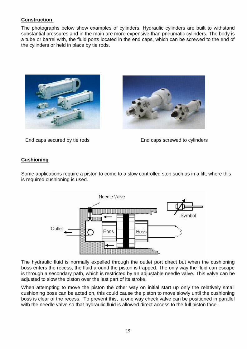
Construction
The photographs below show examples of cylinders. Hydraulic cylinders are built to withstand substantial pressures and in the main are more expensive than pneumatic cylinders. The body is a tube or barrel with, the fluid ports located in the end caps, which can be screwed to the end of the cylinders or held in place by tie rods.
End caps secured by tie rods End caps screwed to cylinders
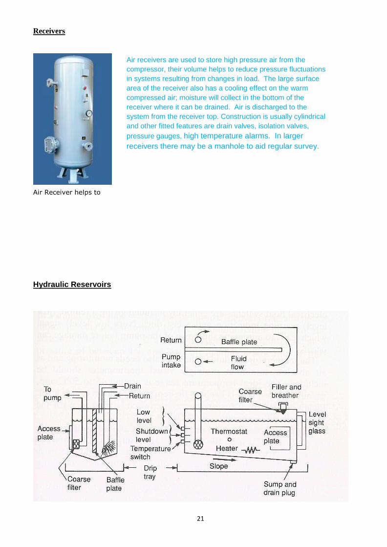
Cushioning
Some applications require a piston to come to a slow controlled stop such as in a lift, where this is required cushioning is used.
The hydraulic fluid is normally expelled through the outlet port direct but when the cushioning boss enters the recess, the fluid around the piston is trapped. The only way the fluid can escape is through a secondary path, which is restricted by an adjustable needle valve. This valve can be adjusted to slow the piston over the last part of its stroke.
When attempting to move the piston the other way on initial start up only the relatively small cushioning boss can be acted on, this could cause the piston to move slowly until the cushioning boss is clear of the recess. To prevent this, a one way check valve can be positioned in parallel with the needle valve so that hydraulic fluid is allowed direct access to the full piston face.

20
End fixing diagrams
The following diagrams show typical ways of mounting cylinders and attaching them to machines.
Accumulators
A hydraulic accumulator is a device in which potential energy is held under pressure in the form of a compressed gas or spring or by a raised weight to be used to exert a force against a relatively incompressible fluid.
Accumulators are used in fluid power systems to store energy and to smooth out pulsation. They can be used to supplement a fluid pump allowing a smaller pump to be fitted.
This is done by storing energy from the pump during low demand periods. They can also be used as surge or pulsation dampeners which will cushion hammer and reduce shocks caused by rapid operation or sudden starting and stopping of power cylinders in a hydraulic circuit.
Accumulators can be used to stabilize pressure changes in hydraulic systems when liquid is subjected to rising or falling temperatures. They may be used to dispense fluids under pressure, such as lubricating greases and oils.
The most common accumulators used today are hydro-pneumatic types. They use a gas as a spring cushion in conjunction with a hydraulic fluid, the gas being separated by a piston or a thin diaphragm or bladder. Other types of accumulator can be spring loaded or use a heavy weight, a typical example is a Gasometer.
21
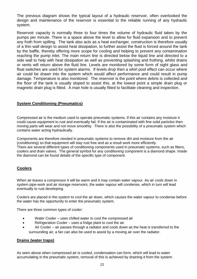
Receivers
Air Receiver helps to
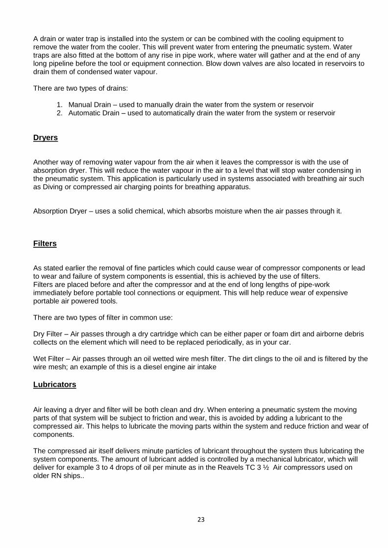
Hydraulic Reservoirs
Air receivers are used to store high pressure air from the
compressor, their volume helps to reduce pressure fluctuations
in systems resulting from changes in load. The large surface
area of the receiver also has a cooling effect on the warm
compressed air; moisture will collect in the bottom of the
receiver where it can be drained. Air is discharged to the
system from the receiver top. Construction is usually cylindrical
and other fitted features are drain valves, isolation valves,
pressure gauges, high temperature alarms. In larger
receivers there may be a manhole to aid regular survey.
22
The previous diagram shows the typical layout of a hydraulic reservoir, often overlooked the design and maintenance of the reservoir is essential to the reliable running of any hydraulic system.
Reservoir capacity is normally three to four times the volume of hydraulic fluid taken by the pumps per minute. There is a space above the level to allow for fluid expansion and to prevent any froth from spilling. The tank also acts as a heat exchanger, construction is therefore usually of a thin wall design to assist heat dissipation, to further assist the fluid is forced around the tank by the baffle, thereby offering more scope for cooling and helping to prevent any contamination reaching the pump inlet. The main return line is directed below the liquid line and directed to a side wall to help with heat dissipation as well as preventing splashing and frothing, whilst drains or vents will return above the fluid line. Levels are monitored by some form of sight glass and float switches are used for system alarms. If levels drop then a whirl pool effect can occur where air could be drawn into the system which would affect performance and could result in pump damage. Temperature is also monitored. The reservoir is the point where debris is collected and the floor of the tank is usually sloped to assist this, at the lowest point a simple drain plug or magnetic drain plug is fitted. A man hole is usually fitted to facilitate cleaning and inspection.
System Conditioning (Pneumatics)
Compressed air is the medium used to operate pneumatic systems. If this air contains any moisture it could cause equipment to rust and eventually fail. If the air is contaminated with fine solid particles then moving parts will wear and not move smoothly. There is also the possibility of a pneumatic system which contains water acting hydraulically. Components are therefore needed in pneumatic systems to remove dirt and moisture from the air (conditioning) so that equipment will stay rust free and as a result work more efficiently. There are several different types of conditioning components used in pneumatic systems, such as filters, coolers and drain valves. The general symbol for any conditioning component is a diamond shape. Inside the diamond can be found details of the specific type of component.
Coolers
When air leaves a compressor it will be warm and it may contain water vapour. As air cools down in system pipe-work and air storage reservoirs, the water vapour will condense, which in turn will lead eventually to rust developing. Coolers are placed in the system to cool the air down, which causes the water vapour to condense before the water has the opportunity to enter the pneumatic system. There are three common types of cooler:
Water Cooler – uses chilled water to cool the compressed air
Refrigeration Cooler – uses a fridge plant to cool the air.
Air Cooler – air passes through a radiator and cools down as the heat is transferred to the
surrounding air, a fan can also be used to assist by a moving air over the radiator.
Drains (water traps)
As seen above when compressed air is cooled, condensation can form, which will lead to water accumulating in the pneumatic system, removal of this is achieved by draining it from the system.
23
A drain or water trap is installed into the system or can be combined with the cooling equipment to remove the water from the cooler. This will prevent water from entering the pneumatic system. Water traps are also fitted at the bottom of any rise in pipe work, where water will gather and at the end of any long pipeline before the tool or equipment connection. Blow down valves are also located in reservoirs to drain them of condensed water vapour. There are two types of drains:
1. Manual Drain – used to manually drain the water from the system or reservoir 2. Automatic Drain – used to automatically drain the water from the system or reservoir
Dryers
Another way of removing water vapour from the air when it leaves the compressor is with the use of absorption dryer. This will reduce the water vapour in the air to a level that will stop water condensing in the pneumatic system. This application is particularly used in systems associated with breathing air such as Diving or compressed air charging points for breathing apparatus.
Absorption Dryer – uses a solid chemical, which absorbs moisture when the air passes through it.
Filters
As stated earlier the removal of fine particles which could cause wear of compressor components or lead to wear and failure of system components is essential, this is achieved by the use of filters. Filters are placed before and after the compressor and at the end of long lengths of pipe-work immediately before portable tool connections or equipment. This will help reduce wear of expensive portable air powered tools. There are two types of filter in common use: Dry Filter – Air passes through a dry cartridge which can be either paper or foam dirt and airborne debris collects on the element which will need to be replaced periodically, as in your car. Wet Filter – Air passes through an oil wetted wire mesh filter. The dirt clings to the oil and is filtered by the wire mesh; an example of this is a diesel engine air intake
Lubricators
Air leaving a dryer and filter will be both clean and dry. When entering a pneumatic system the moving parts of that system will be subject to friction and wear, this is avoided by adding a lubricant to the compressed air. This helps to lubricate the moving parts within the system and reduce friction and wear of components. The compressed air itself delivers minute particles of lubricant throughout the system thus lubricating the system components. The amount of lubricant added is controlled by a mechanical lubricator, which will deliver for example 3 to 4 drops of oil per minute as in the Reavels TC 3 ½ Air compressors used on older RN ships..
24
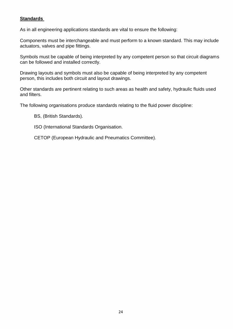
Standards
As in all engineering applications standards are vital to ensure the following:
Components must be interchangeable and must perform to a known standard. This may include actuators, valves and pipe fittings. Symbols must be capable of being interpreted by any competent person so that circuit diagrams can be followed and installed correctly. Drawing layouts and symbols must also be capable of being interpreted by any competent person, this includes both circuit and layout drawings. Other standards are pertinent relating to such areas as health and safety, hydraulic fluids used and filters. The following organisations produce standards relating to the fluid power discipline: BS, (British Standards). ISO (International Standards Organisation. CETOP (European Hydraulic and Pneumatics Committee).

25
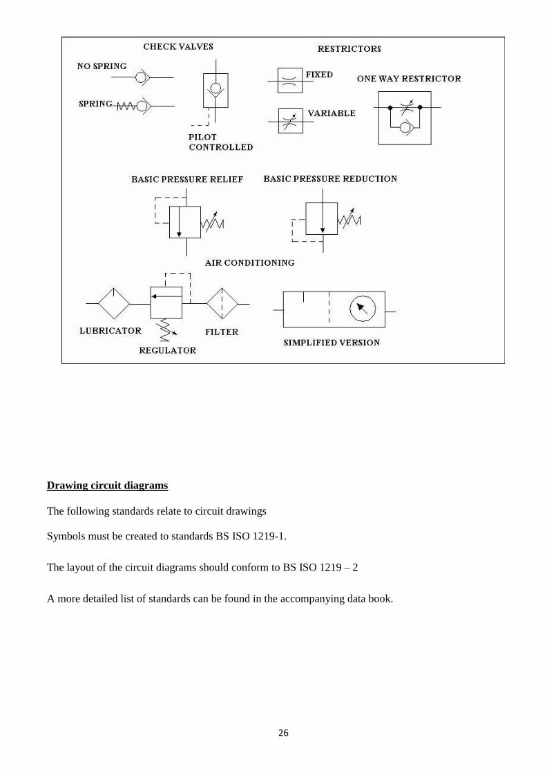
Symbols
26
Drawing circuit diagrams
The following standards relate to circuit drawings
Symbols must be created to standards BS ISO 1219-1.
The layout of the circuit diagrams should conform to BS ISO 1219 – 2
A more detailed list of standards can be found in the accompanying data book.

27
Numbering system
Components are identified by a number which should consist of four parts. For example consider the
following: 2 – 3V5
The first number (2) is the installation number. If there is only one, it may be omitted.
The second number (3) is the circuit number, as above if there is only one, it can be omitted. The number 0
is used for the drawing of the power pack and accessories.
The letter identifies the type of component as shown in the following table:
P Pump
A Actuator
M Prime mover
S Sensor
V Valve
Z Any other component
The last number is the sequence number of the component so V5 would mean valve number 5.
Pipes
Pipes shown on drawings are assigned the following letters:
P Pressure lines
T Tank or return lines
L Leakage / drain lines
Each should be numbered starting with 1 and a different number used for pipes at different operating
pressures.
The following drawings show how these are used.

28
EXAMPLE OF A CIRCUIT DRAWING
Parts list
29
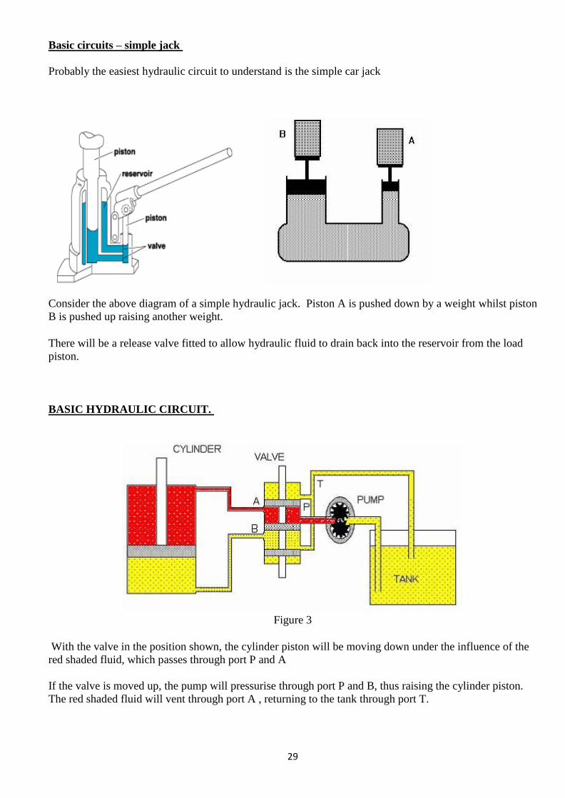
Basic circuits – simple jack
Probably the easiest hydraulic circuit to understand is the simple car jack
Consider the above diagram of a simple hydraulic jack. Piston A is pushed down by a weight whilst piston
B is pushed up raising another weight.
There will be a release valve fitted to allow hydraulic fluid to drain back into the reservoir from the load
piston.
BASIC HYDRAULIC CIRCUIT.
Figure 3
With the valve in the position shown, the cylinder piston will be moving down under the influence of the
red shaded fluid, which passes through port P and A
If the valve is moved up, the pump will pressurise through port P and B, thus raising the cylinder piston.
The red shaded fluid will vent through port A , returning to the tank through port T.
30