fluidmaster 400uk bottom inlet valve installation ... · 7. important: always clear debris from...

3
7. IMPORTANT: ALWAYS CLEAR DEBRIS FROM WATER LINE TO COMPLETE INSTALLATION.Shut off water supply to cistern. Remove VALVE TOP by lifting arm and rotating TOP 1/8 turn anti-clockwise, pressing down slightly on cap. While holding a container over the uncapped VALVE to prevent splashing, turn water supply on and off to clear debris that may be in supply line. Turn off water supply and replace TOP by engaging lugs and rotating 1/8 turn clockwise. MAKE CERTAIN TOP IS TURNED TO THE LOCKED POSITION. VALVE MAY NOT TURN ON IF TOP IS NOT FULLY TO THE LOCKED POSITION. Turn off water supply. For more information in the U.K. contact: Fluidmaster UK One Harbour Road Portishead, Bristol BS20 7BL Tel: 01275 84 88 43 FAX: 01275 81 74 37 EMAIL: [email protected] WEB: www.fluidmasterUK.com TO GET THE BEST RESULTS FROM YOUR FLUIDMASTER VALVE, PLEASE READ THESE INSTRUCTIONS CAREFULLY. NOTE: SAVE INSTRUCTION SHEET FOR FUTURE REFERENCE CONCERNING THIS VALVE’S OPERATION AND MAINTENANCE. IMPORTANT: DO NOT use plumber’s putty to seal this fitting. 1. Turn off water supply to toilet cistern at storage tank in loft or isolator valve if mains fed. 2. Disconnect pipe work and remove old valve from toilet cistern 5. Install valve inside cistern. Start to thread back nut onto threaded shank so the shank protrudes through the cistern enough to enable tap connector to fit neatly. Do not tighten back nut at this stage. 6. When position is correct and before tightening back nut, reconnect water supply to valve to make sure fibre washer is sealed correctly. Tighten tap connector 1/4 turn past hand tight with spanner (DO NOT OVERTIGHTEN). Now tighten back nut with spanner 1/4 turn past hand tight (DO NOT OVERNIGHTEN). Turn on main water supply. 8. Adjust the water to the desired level by turning the water level adjustment rod and moving float cup up or down. Water should be set to water line on cistern. 3. Place sealing washer on threaded shank of valve. Position valve in toilet cistern, passing threaded shank through hole in cistern to determine if valve height needs adjusting. 4. The Fluidmaster 400UK valve is adjustable in height from 225mm (9 inches) to 350mm (14 inches). To adjust height of valve, remove from toilet cistern and twist threaded shank in or out of valve body. A clicking noise will be heard on some models. This is normal. The valve height should be adjusted so that the critical level mark on the valve body is located at least 25mm (1 inch) above the overflow pipe in the cistern. FLUIDMASTER 400UK BOTTOM INLET VALVE INSTALLATION INSTRUCTIONS FOR TOILET CISTERN WARNING: Fluidmaster shall not be responsible or liable for any failure of, or damage to, this plumbing product caused by use of chlorine (bleach) cleaners or related products added to the toilet cistern. Use of such products will void the warranty and may result in product failure, possibly causing property damage. Do not overtighten plastic nuts. P/N #446-1 Rev. 3 05/12 GUARANTEE: This Fluidmaster product is guaranteed to be free from defective materials and workmanship for a period of one year. Units returned to Fluidmaster, USA, or Fluidmaster UK will be replaced without charge. Always use quality Fluidmaster repair parts when maintaining your Fluidmaster products. Fluidmaster shall not be responsible or liable for any damages caused by products used in Fluidmaster valves that were not manufactured by Fluidmaster, Inc. 1. Turn off water supply as in Figure 1 of instructions. 2. Remove upper cap assembly by lifting arm and rotating 1/8 anti-clockwise. 3. Replace seal and refit upper cap assembly. Make sure upper assembly is fully turned clockwise to the stop. 4. Turn on water supply as before. LIFT ARM TROUBLESHOOTING - SEAL REPLACEMENT: If valve won’t turn on or shut off or refill of cistern water is slow after valve has been in use for some time, a replacement seal may be needed. Ask your dealer for Model 242MP071 and install as follows: 1. Turn off water supply in Figure 1 of instructions. 2. Remove water level adjustment rod from upper cap assembly as shown. 3. Remove upper cap assembly by lifting arm and rotating 1/8 anti- clockwise, pressing down slighty on cap. 4. Replace seal. 5. Hold a cup over the uncapped valve (to prevent splashing), and turn water supply on and off to clear debris in supply. 6. Refit upper cap assembly. Make sure assembly is fully turned clockwise to the locked position or valve will not turn on. Reattach water level adjustment rod to upper assembly by snapping back in place. 7. Turn on water supply as before.

Upload: vuongbao

Post on 08-Aug-2018

215 views

Category:

Documents


0 download

TRANSCRIPT

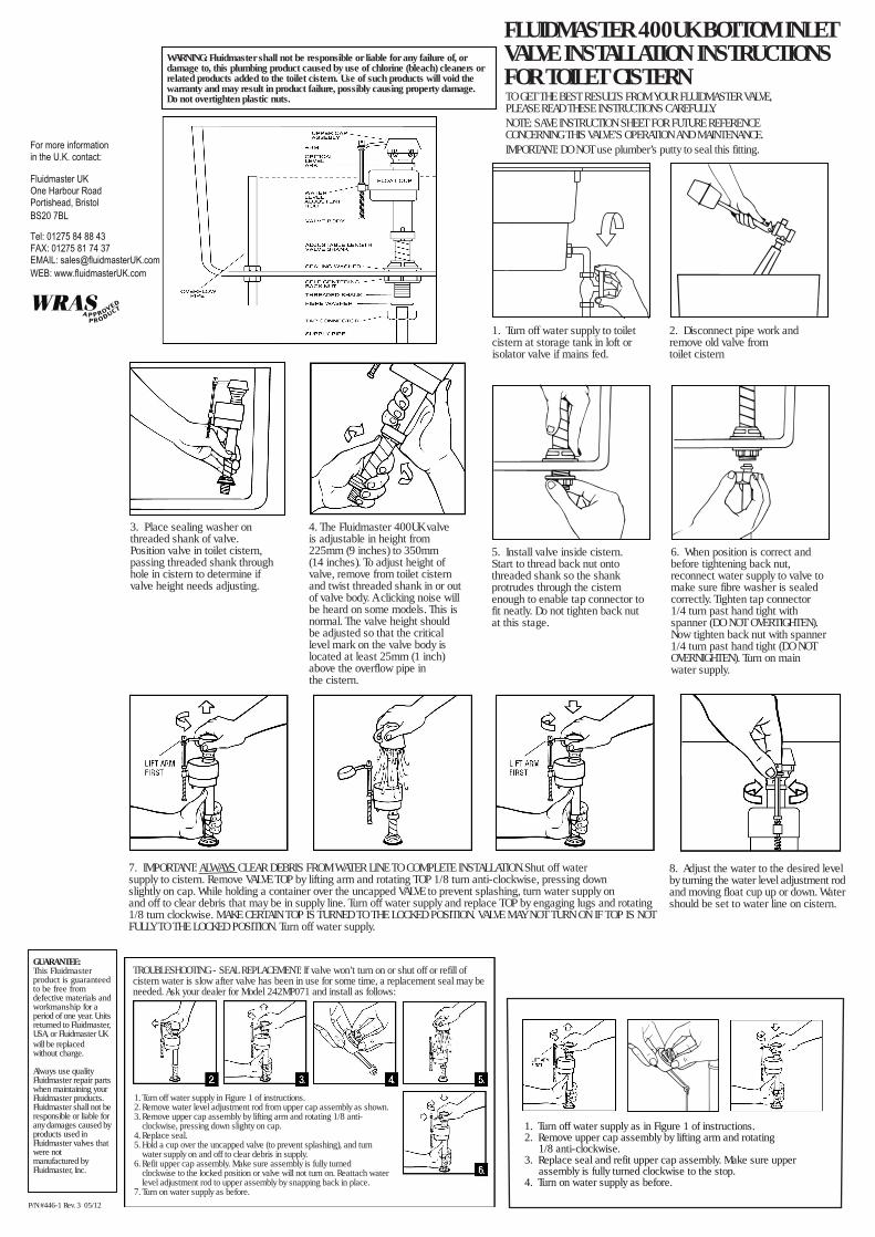
7. IMPORTANT: ALWAYS CLEAR DEBRIS FROM WATER LINE TO COMPLETE INSTALLATION.Shut off watersupply to cistern. Remove VALVE TOP by lifting arm and rotating TOP 1/8 turn anti-clockwise, pressing downslightly on cap. While holding a container over the uncapped VALVE to prevent splashing, turn water supply onand off to clear debris that may be in supply line. Turn off water supply and replace TOP by engaging lugs and rotating1/8 turn clockwise. MAKE CERTAIN TOP IS TURNED TO THE LOCKED POSITION. VALVE MAY NOT TURN ON IF TOP IS NOTFULLY TO THE LOCKED POSITION. Turn off water supply.

For more informationin the U.K. contact:

Fluidmaster UKOne Harbour RoadPortishead, BristolBS20 7BL

Tel: 01275 84 88 43FAX: 01275 81 74 37EMAIL: [email protected]: www.fluidmasterUK.com

TO GET THE BEST RESULTS FROM YOUR FLUIDMASTER VALVE,PLEASE READ THESE INSTRUCTIONS CAREFULLY.NOTE: SAVE INSTRUCTION SHEET FOR FUTURE REFERENCECONCERNING THIS VALVE’S OPERATION AND MAINTENANCE.IMPORTANT: DO NOT use plumber’s putty to seal this fitting.

1. Turn off water supply to toiletcistern at storage tank in loft orisolator valve if mains fed.

2. Disconnect pipe work andremove old valve fromtoilet cistern

5. Install valve inside cistern.Start to thread back nut ontothreaded shank so the shankprotrudes through the cisternenough to enable tap connector tofit neatly. Do not tighten back nutat this stage.

6. When position is correct andbefore tightening back nut,reconnect water supply to valve tomake sure fibre washer is sealedcorrectly. Tighten tap connector1/4 turn past hand tight withspanner (DO NOT OVERTIGHTEN).Now tighten back nut with spanner1/4 turn past hand tight (DO NOTOVERNIGHTEN). Turn on mainwater supply.

8. Adjust the water to the desired levelby turning the water level adjustment rodand moving float cup up or down. Watershould be set to water line on cistern.

3. Place sealing washer onthreaded shank of valve.Position valve in toilet cistern,passing threaded shank throughhole in cistern to determine ifvalve height needs adjusting.

4. The Fluidmaster 400UK valveis adjustable in height from225mm (9 inches) to 350mm(14 inches). To adjust height ofvalve, remove from toilet cisternand twist threaded shank in or outof valve body. A clicking noise willbe heard on some models. This isnormal. The valve height shouldbe adjusted so that the criticallevel mark on the valve body islocated at least 25mm (1 inch)above the overflow pipe inthe cistern.

FLUIDMASTER 400UK BOTTOM INLETVALVE INSTALLATION INSTRUCTIONSFOR TOILET CISTERN

WARNING: Fluidmaster shall not be responsible or liable for any failure of, ordamage to, this plumbing product caused by use of chlorine (bleach) cleaners orrelated products added to the toilet cistern. Use of such products will void thewarranty and may result in product failure, possibly causing property damage.Do not overtighten plastic nuts.

P/N #446-1 Rev. 3 05/12

GUARANTEE:This Fluidmasterproduct is guaranteedto be free fromdefective materials andworkmanship for aperiod of one year. Unitsreturned to Fluidmaster,USA, or Fluidmaster UKwill be replacedwithout charge.

Always use qualityFluidmaster repair partswhen maintaining yourFluidmaster products.Fluidmaster shall not beresponsible or liable forany damages caused byproducts used inFluidmaster valves thatwere notmanufactured byFluidmaster, Inc.

1. Turn off water supply as in Figure 1 of instructions.2. Remove upper cap assembly by lifting arm and rotating 1/8 anti-clockwise.3. Replace seal and refit upper cap assembly. Make sure upper assembly is fully turned clockwise to the stop.4. Turn on water supply as before.

LIFTARM

TROUBLESHOOTING - SEAL REPLACEMENT: If valve won’t turn on or shut off or refill ofcistern water is slow after valve has been in use for some time, a replacement seal may beneeded. Ask your dealer for Model 242MP071 and install as follows:

1. Turn off water supply in Figure 1 of instructions.2. Remove water level adjustment rod from upper cap assembly as shown.3. Remove upper cap assembly by lifting arm and rotating 1/8 anti-

clockwise, pressing down slighty on cap.4. Replace seal.5. Hold a cup over the uncapped valve (to prevent splashing), and turn

water supply on and off to clear debris in supply.6. Refit upper cap assembly. Make sure assembly is fully turned

clockwise to the locked position or valve will not turn on. Reattach waterlevel adjustment rod to upper assembly by snapping back in place.

7. Turn on water supply as before.