fluorinated electrolyte for 5-v li-ion chemistry electrolyte for 5-v li-ion chemistry doe annual...
TRANSCRIPT
Fluorinated Electrolyte for 5-V Li-Ion Chemistry
DOE Annual Merit Review MeetingWashington D.C.
June 8-12, 2015
Project ID #: ES218
Zhengcheng(John) Zhang (PI)Kang Xu (Co-PI), Xiao-Qing Yang (Co-PI)
Argonne National Laboratory
This presentation does not contain any proprietary, confidential, or otherwise restricted information
Project Overview
Timeline Barriers
Budget Partners
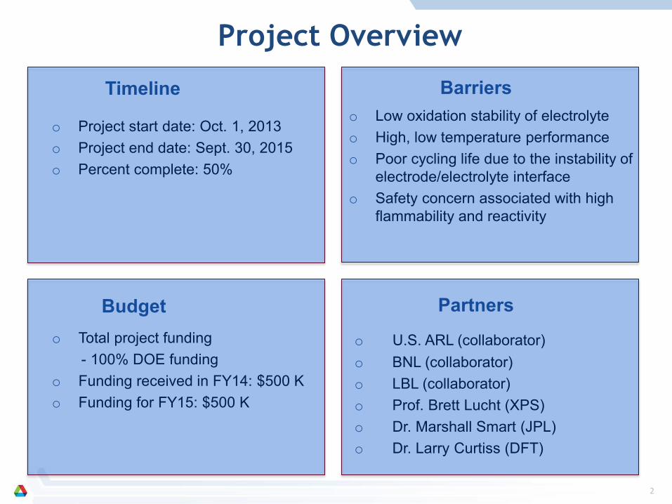
o Project start date: Oct. 1, 2013 o Project end date: Sept. 30, 2015 o Percent complete: 50%
o Low oxidation stability of electrolyte o High, low temperature performanceo Poor cycling life due to the instability of
electrode/electrolyte interfaceo Safety concern associated with high
flammability and reactivity
o Total project funding- 100% DOE funding
o Funding received in FY14: $500 Ko Funding for FY15: $500 K
o U.S. ARL (collaborator)o BNL (collaborator)o LBL (collaborator)o Prof. Brett Lucht (XPS)o Dr. Marshall Smart (JPL)o Dr. Larry Curtiss (DFT)
2
3
Project Objective
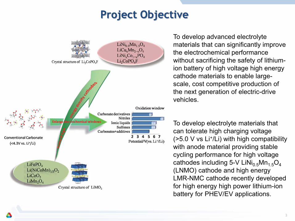
To develop advanced electrolyte materials that can significantly improve the electrochemical performance without sacrificing the safety of lithium-ion battery of high voltage high energy cathode materials to enable large-scale, cost competitive production of the next generation of electric-drive vehicles.
To develop electrolyte materials that can tolerate high charging voltage (>5.0 V vs Li+/Li) with high compatibility with anode material providing stable cycling performance for high voltage cathodes including 5-V LiNi0.5Mn1.5O4(LNMO) cathode and high energy LMR-NMC cathode recently developed for high energy high power lithium-ion battery for PHEV/EV applications.
3
Technical Approach/Strategy
LUMO
HOMO
µa
µc
Ecell
Anode
Cathode
LUMO
HOMO
µa (Li, C or Si)
Ecell = 4.3 ev
SEI
Ideal Unknown Electrolytes
LUMO
HOMOµc
SEI
Ecell = 4.7 ev
Anode
Cathode µc (LiMO2)
Anode
Cathode
µa (Li, C or Si)
Cathode Passivation Additive
LUMO
HOMOµc (LiNi0.5Mn1.5O4)
SEI
Ecell = > 4.7 ev
Anode
Cathode
µa (Li, C or Si)
SEI
New Solvents with Intrinsic Stability
SOA Carbonate Electrolytes
µa (LTO)
Ecell = 3.2 ev Ecell = 3.2 ev
µa (LTO)
Ewindow Ewindow
EwindowEwindow
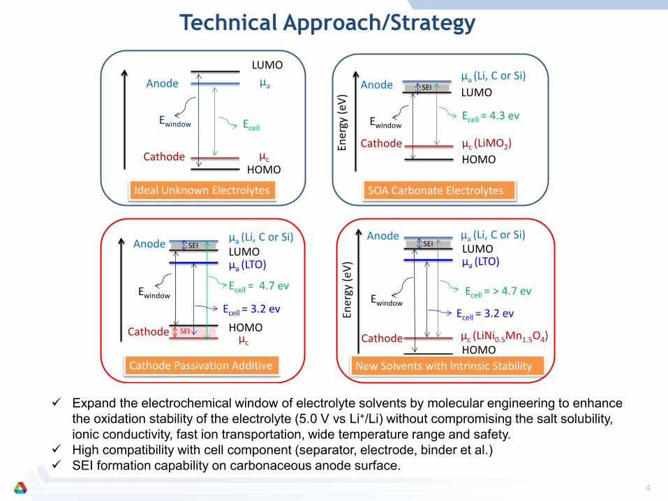
Expand the electrochemical window of electrolyte solvents by molecular engineering to enhancethe oxidation stability of the electrolyte (5.0 V vs Li+/Li) without compromising the salt solubility,ionic conductivity, fast ion transportation, wide temperature range and safety.
High compatibility with cell component (separator, electrode, binder et al.) SEI formation capability on carbonaceous anode surface.
4
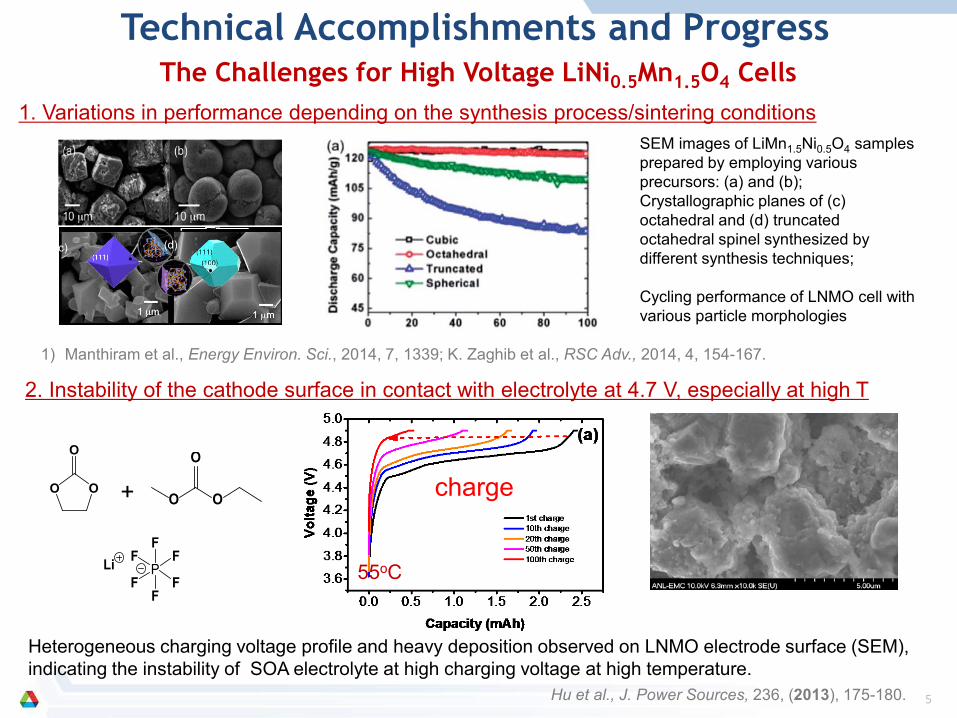
The Challenges for High Voltage LiNi0.5Mn1.5O4 Cells1. Variations in performance depending on the synthesis process/sintering conditions
SEM images of LiMn1.5Ni0.5O4 samples prepared by employing various precursors: (a) and (b); Crystallographic planes of (c) octahedral and (d) truncated octahedral spinel synthesized by different synthesis techniques;
Cycling performance of LNMO cell with various particle morphologies
1) Manthiram et al., Energy Environ. Sci., 2014, 7, 1339; K. Zaghib et al., RSC Adv., 2014, 4, 154-167.
(c) (d)
2. Instability of the cathode surface in contact with electrolyte at 4.7 V, especially at high T
charge
55oC
Heterogeneous charging voltage profile and heavy deposition observed on LNMO electrode surface (SEM), indicating the instability of SOA electrolyte at high charging voltage at high temperature.
OO
O
O O
O
P
F
FF
F
FFLi
+
Hu et al., J. Power Sources, 236, (2013), 175-180.
Technical Accomplishments and Progress
5

Molecular StructureOxidation Potential (Pox/V)
Anion EffectPotential (Pox/V)
Reduction Potential (Pred/V)
Stretch Bond Potentials (Pred/V)
7.10 (6.62, EMC)6.26 (PF6: HF forms)5.79 (TFSI: H transfer) 0.03
1.40 (CF3CH2-O)1.49 (CH3-O)
7.70 (6.46)6.28 (PF6)5.83 (TFSI) 0.30
7.96 (6.46)7.69 (PF6)5.76 (TFSI) 1.29
1.54 (CF3CH2-O)2.39 ((CF3)2CH-O1.47 (CF3-O)
7.25 (6.51, DEC)7.35 (PF6)- 0.22 1.65 (CF3CH2-O)
7.30 (6.80, PC)6.21 (PF6)5.33, 5.44, 5.87 (TFSI)
1.54 (spontaneous C-O bond opening)
7.24 (6.95, EC)6.44 (PF6)5.80 (TFSI) 0.33 1.56 (CHF-O)
6.97
6.246.05 (PF6)5.90, 5.19, 5.22 (TFSI) 0.01 1.50
Electron-withdrawing groups of -F and -Rf groups lower the energy level of the HOMO, thus increasethe theoretical oxidation stability of the F-compounds.
The electron-withdrawing effect varies with the structure and the position of the substitution groups.
OO
O
CF3
OO
O
F
CO
O
O
CF3
CF3
F
OF2C
CHF2
OO
O
OO
O
CF3
OO
O
CF3
CF3
OOF3C
O
CF3
CF3
OO
O
CF3F3C
Electron-Withdrawing Effect of F- and F-alkyl by DFT
6

7
Synthesis of Fluorinated Carbonates
F-EMC
TF-DEC
FMiPC
HF-DEC
TFPC
TFP-PC-E
OF2C
CHF2
OO
O
ab,cd,e
f
g,h
af
g,h
b,c
d,e
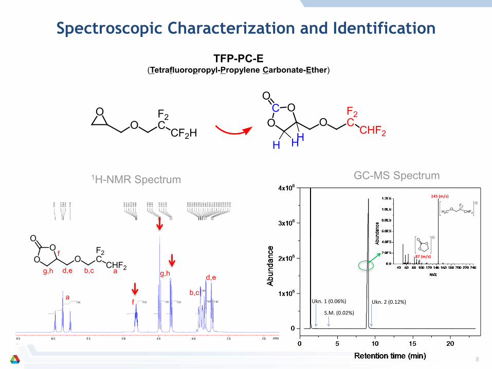
145 (m/z)
87 (m/z)
OO
O
H2CO
F2C
CHF2
S.M. (0.02%)
Ukn. 1 (0.06%) Ukn. 2 (0.12%)
TFP-PC-E(Tetrafluoropropyl-Propylene Carbonate-Ether)
OO
F2C
CF2HO
F2C
CHF2
OCO
O
H HH
Spectroscopic Characterization and Identification
1H-NMR Spectrum GC-MS Spectrum
8

0.5M LiPF6 in F-cyclic carbonate/F-EMC=1:1 (v/v); LNMO/Li half cell, fully charged at 4.9, 5.0, 5.1 and 5.2V
Oxidation Stability of Cyclic F-Carbonates
F-cyclic carbonate FEC > TFPC > EC > TFE-PC-Eoxidation stability:
OO
O
F
OO
O
CF3
OO
O
OF2C
CHF2
OO
O
> > >
0 10 20 30 400.00
0.02
0.04
0.06
0.08
0.10
0.12
0.14
0.16
0.18
0.20 EC/F-EMC TFPC/F-EMC FEC/F-EMC TFE-PC-E/F-EMC
Time (h)
Cur
rent
(mA
)
RT
5.2V5.1V5.0V4.9V
0 10 20 30 400.00
0.02
0.04
0.06
0.08
0.10
0.12
0.14
0.16
0.18
0.20 EC/F-EMC TFPC/F-EMC FEC/F-EMC TFE-PC-E/F-EMC
Time (h)
Cur
rent
(mA
)
55 C
5.2V
5.1V5.0V4.9V55oC
F-electrolyte showed small difference in leakage current at RT; at 55oC, the current increases significantly Due to the catalytic reaction at the interface of LNMO/electrolyte at high temperature, EC and TFE-PC-E is
extremely unstable.
CO
O
O
CF3
CF3
F
9

HF-DEC > TF-DEC ≈ F-EMC > DMC
O O
O
OO
O
CF3OO
O
CF3F3C OO
O
CF3
* Oxidation stability at room temperature; high temperature data deviates from the RT data due to the thermal decomposition.
0.5 M LiPF6 in FEC/F-linear carbonate = 1:1 (v/v); LNMO/Li half cell, fully charged at 4.9, 5.0, 5.1 and 5.2 V at RT and 55oC.
0 10 20 30 400.00
0.02
0.04
0.06
0.08
0.10
0.12
0.14
Time (h)
Cur
rent
(mA
)
RT FEC/F-EMC FEC/TF-DEC FEC/DMC FEC/HF-DEC
5.2V5.1V5.0V4.9V
0 10 20 30 400.000.020.040.060.080.100.120.140.160.180.200.220.24
Time (h)C
urre
nt (m
A)
55C FEC/F-EMC FEC/TF-DEC FEC/DMC FEC/HF-DEC
5.2V5.1V5.0V4.9V
> ≈ >
55oC ?
Oxidation Stability of Linear F-Carbonates
10

Mixed Solvent Ratio and Salt Concentration on Oxidation
0 10 20 30 40 50 60 70 80 90
4
6
8
10
12
14
16
18
20
22
245.2 V
5.1 V
5.0 V
Cur
rent
(uA
)
FEC content (%)
4.9 V
0.5 M LiPF6 in FEC:DMC (from 1:9 to 9:1) FEC:DMC = 5:5 with LiPF6 from 0.5 M to 1.25 M
FEC content affects the voltage stability at high charge voltages, but less significant at lower voltages (4.9 and 5.0V)
0.00 0.25 0.50 0.75 1.00 1.25 1.50
4
6
8
10
12
14
5.2 V
5.1 V
5.0 V
Cur
rent
(uA
)
FEC content (%)
4.9 V
No significant effect of LiPF6 salt concentration on voltage stability, especially at charge voltages below 5 V.
11

0 1 2 3 4 50.0
0.5
1.0
1.5 1st cycle
Volta
ge (V
)
Capacity (mAh)
OF2C
CHF2
OO
O
OO
O
CF3
00.5
11.5
22.5
33.5
44.5
5
0 1 2 3 4 5
Volta
ge/ V
Capacity/ mAh
FEC_Full cellFEC_Anode
A12 anode
F
OO
O
0.0
0.2
0.4
0.6
0.8
1.0
1.2
1.4
1.6
1.8
2.0
2.2
0 1 2 3 4
Vol
tage
(V)
Capacity (mAh)
Gen 2
CO
O
O
CF3
CF3
F
0 50 100 150 200 250 300 350 400 450
0.0
0.5
1.0
1.5
2.0
2.5
3.0
Gen 2 TFPC-3
Volta
ge (V
)
Capacity (mAh/g)
Compatibility of Electrolytes with Graphite Anode
12

Fluorinated Electrolyte for LNMO/Graphite Full Cell
F-EC(3) F-EMC(5) F-EPE(2) LiPF6 (1.0 M) LiDFOB (1%)
HVE 3 shows great compatibility with graphite surface as indicated by the improvement in LNMO/graphite cells comparedwith Gen 2 electrolyte, especially at 55 ºC.
0 20 40 60 80 1000
20
40
60
80
100
120
140
160
180
Capa
city
(mAh
g-1
)
Cycle Number
HVE 3 Charge HVE 3 Discharge Gen 2 Charge Gen 2 Discharge
(a)95
96
97
98
99
100
101
HVE 3 Coulombic efficiency Gen 2 Coulombic efficiency Co
ulom
bic
Effic
ienc
y (%
)
25 oC
0 20 40 60 80 1000
20
40
60
80
100
120
140
Capa
city
(mAh
g-1
)
Cycle Number
HVE 3 Charge HVE 3 Discharge Gen 2 Charge Gen 2 Discharge
55 oC
86
88
90
92
94
96
98
100
HVE 3 Coulombic efficiency Gen 2 Coulombic efficiency
Coul
ombi
c Ef
ficie
ncy
(%)
(b)LNMO/graphite, 3.5-4.9 V
Hu, Zhang et al. Electrochem. Commun., 2013, 35, 76.
HVE3HVE3
OO
O
F
O
OO CF3F2HC
CF2
O
F2C
CF2H P
F
FF
F
FFLi
OB
O F
F
O
O
Li+ ++ +
13
0 5 10 15 200
1
2
3
4
5
HVE-3 electrolyte @ RT HVE-3 electrolyte @ 55 oC Gen 2 electrolyte @ RT Gen 2 electrolyte @ 55 oC
Volta
ge (V
)
Time (day)
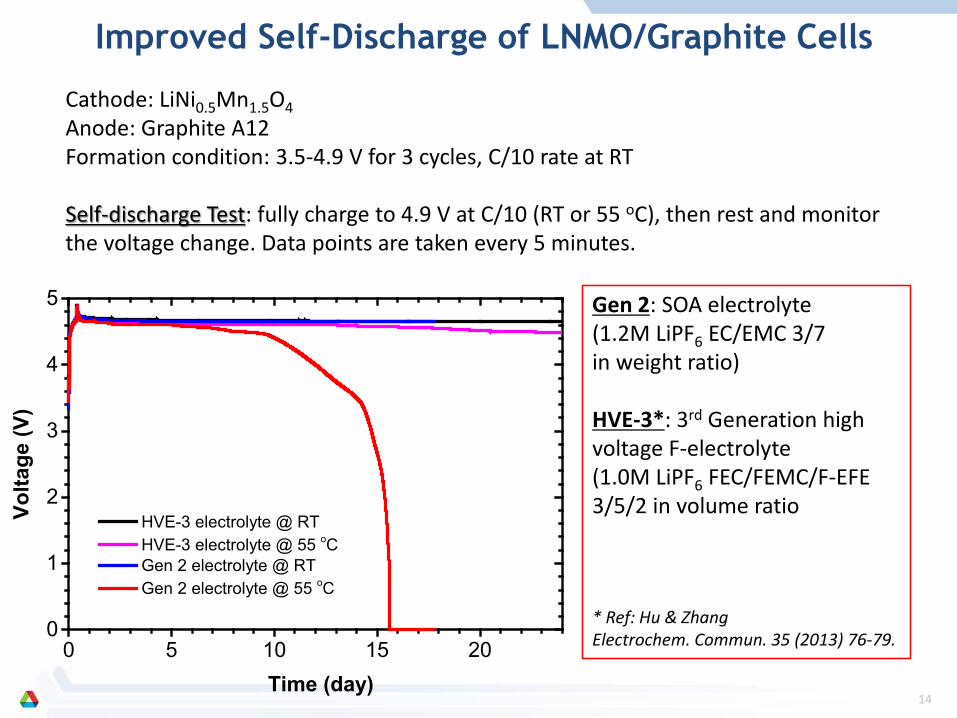
Cathode: LiNi0.5Mn1.5O4Anode: Graphite A12Formation condition: 3.5-4.9 V for 3 cycles, C/10 rate at RT
Self-discharge Test: fully charge to 4.9 V at C/10 (RT or 55 oC), then rest and monitor the voltage change. Data points are taken every 5 minutes.
Gen 2: SOA electrolyte (1.2M LiPF6 EC/EMC 3/7 in weight ratio)
HVE-3*: 3rd Generation high voltage F-electrolyte(1.0M LiPF6 FEC/FEMC/F-EFE 3/5/2 in volume ratio
* Ref: Hu & Zhang Electrochem. Commun. 35 (2013) 76-79.
Improved Self-Discharge of LNMO/Graphite Cells
14
Gen 2 HVE 3
1.2M LiPF6 EC/EMC 3/7 weight 1.0M LiPF6 FEC/F-EMC/F-EPE 3/5/2 in volume
Fluorinated Electrolytes are Not Flammable
Video Here Video Here
15

TEM Characterization of Cycled LNMO Cathode
Etching of LNMO particles is pronounced in baseline cell due to the oxidative decompositionof EC-EMC solvents and the generation of HF leading to Mn and Ni dissolution.
Mn and Ni exist in the cycled baseline electrolyte with much higher concentration (ICP-MSdata, not shown).
LNMO surface is intact with HVE electrolyte, and more integrated when LiDFOB additive wasemployed, indicating the improved chemical and electrochemical stability of F-electrolyte.
Gen 2 HVE 3 HVE 3+ Additive
16

0 1 2 3 4 5 6 7 8 9 10-50
0
50
100
150
200
250
300
350
400
450
500
550
600
Cu Kβ
F KαP Kα
Cu LαNi Kα
Mn Kα
Cu Kα
O Kα
Cou
nts
E/ KeV
C Kα
0 1 2 3 4 5 6 7 8 9 10-200
0
200
400
600
800
1000
1200
1400
Cu Kβ
Cu Lα
F Kα
P Kα
Ni KαMn Kα
Cu Kα
O Kα
Co
un
ts
E/ KeV
C Kα
0 1 2 3 4 5 6 7 8 9 10
0
1000
2000
3000
4000
5000
6000
Cu KβCu Lα
P Kα
Ni KαMn Kα
Cu Kα
O Kα
Cou
nts
E/ KeV
C Kα
Anode of Gen2 cell showed significant amount of nanoparticles (a few nm) of transitional M species in thecarbon black region, which might catalyze the parasitic reactions.
However, anode of HVE3 + Additive cell showed quite different morphology of the transition M: less amountand deposition/agglomeration (~10nm), less catalytic effect leading to less reductive decomposition ofelectrolyte.
Gen 2 HVE 3 HVE 3 + Additive
pristine
TEM Characterization of Graphite Anode
17

Charging
Li+
Lithiated graphite
Discharge
Partially lithiated graphite
Lithiated LNMO
Li+
Li metal will discharge first
Graphite LNMO
Li
DelithiatedLNMO
Li metal or SLMP
Press and contact with electrolyte
Lithiated graphite
Li metallithiation
Anode Graphite
Lithiated graphite
Graphite anode
Spacer
LNMO cathode
Separator
Spacer
PP gasketWave washer & cap
Case
LiLiLi Li
(a) (b)
(c) (d)
Hu & Zhang et al., Electrochem. Commun., 2014, 44, 34-37.
(a) LNMO/graphite cell assembly with incorporated lithium metal; (b) lithium metal working mechanism at the formation cycles; (c) electrochemical prelithiation of graphite anode; (d) direct shorting of graphite anode and Li.
0 20 40 60 80 1000
20406080
100120140160
Capa
city
(mAh
g-1
)
Cycle Number
HVE with Li metal HVE 4.9 V control Gen 2 4.9 V control
(a)
0 10 20 30 40 50 60 70 80 90 1008687888990919293949596979899
100
Cou
lom
bic
effic
ienc
y / %
Cycle number
55oC
HVE-3 + Li reservoir
HVE3
Gen2
HVE-3 + Li reservoir
Gen2HVE-3
Compensation of Lithium Loss by a Lithium Reservoir
18

Thermal Stability of FEC-Based Electrolytes: An NMR Study
FEC+LiPF6
FEC+LiTFSI
FEC
5 days @ 50oC
1H-NMR
HaHb,c
HaHb,c
FEC+LiPF6
O O
O
F@ 50oC
19F-NMRP
F
FF
F
FFLi
O O
O
FHbHc
Ha
5 days
2 days
O O
O
H H
OO
O
* *H
P
F
FF
F
FFLi
FEC+LiPF6
FEC+LiTFSI
FEC
19
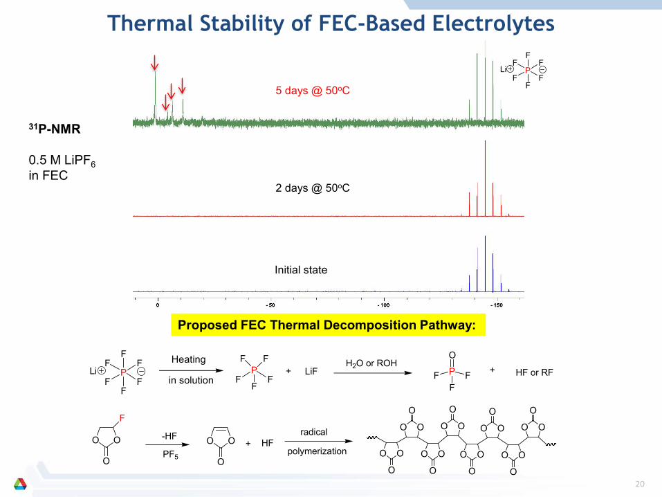
31P-NMR
0.5 M LiPF6in FEC
P
F
FF
F
FFLi
5 days @ 50oC
2 days @ 50oC
Initial state
O O
O
P
F
FF
F
FFLi
F
-HF O O
O
+ HF radical
polymerization O O
O
OO
O
O O
O
OO
O
O O
O
OO
O
O O
O
OO
O
PF
FF
FF+ LiF
H2O or ROHP
FFF
O+ HF or RF
Heating
in solution
PF5
Proposed FEC Thermal Decomposition Pathway:
Thermal Stability of FEC-Based Electrolytes
20

15 days @ 50oC
2 days @ 50oC
2 days @ RT
Pure TFPC (no LiPF6)
Method: 1 M LiPF6 in TFPC, heated @ 50 °C for 15 days
a b c
1H NMR spectra of TFPC-3 electrolyte from harvested LNMO/graphite cells; TFPC remained stable during cycling at high temperature.
Thermal Stability of TF-PC Based Electrolytes
21

0 10 20 30 40 50 60 70 80 90 1000
20
40
60
80
100
120
140
160
180
200
Spe
cific
Cap
acity
(mA
h/g)
Cycle number
50
60
70
80
90
100
Gen 2
TFPC-3
Coulom
bic Efficiency (%
)
0 20 40 60 80 100 120 140 1603.0
3.5
4.0
4.5
5.0
Volta
ge (V
)
Specific Capacity (mAh/g)
3.9 4.2 4.5 4.8-60
-30
0
30
60
90
Voltage (V)
dQ/d
V (m
Ah/
V)
1st cycle, C/10 C/3 @ RT
LNMO/Li half-cell with TFPC-3 electrolyte performs much better than the baseline cell Improved oxidation stability on LNMO Passivation of Li metal anode due to the thermodynamic instability
Cell Performance of TF-PC Based Electrolyte TFPC-3
TFPC-3OO
O
CF3
O
OO CF3P
F
FF
F
FFLi+ + 1.0 M
22
0 10 20 30 40 500
20
40
60
80
100
120
140
160
Spe
cific
Cap
acity
(mA
h/g)
Cycle number
50
60
70
80
90
100
TFPC-3
TFPC-3 + 10 wt% FEC
Coulom
bic Efficiency (%
)
0 20 40 60 80 100 120 140 1600.00.51.01.52.02.53.03.54.04.55.05.5
TFPC-3 TFPC-3 + 10 wt% FEC
Volta
ge (V
)
Specific Capacity (mAh/g)
1st cycle, C/10 C/3 @ RT
2.0 2.2 2.4 2.6 2.8 3.00.0
0.1
0.2
Voltage (V)
dQ/d
V (m
Ah/
V)
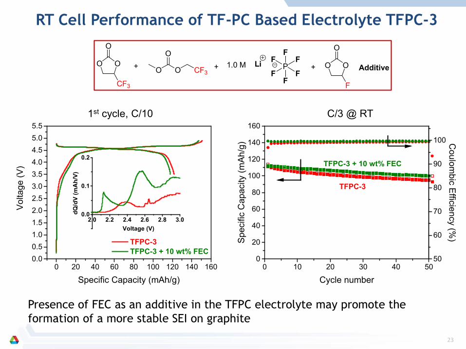
Presence of FEC as an additive in the TFPC electrolyte may promote the formation of a more stable SEI on graphite
OO
O
CF3
O
OO CF3P
F
FF
F
FFLi+ + 1.0 M OO
O
F
+ Additive
RT Cell Performance of TF-PC Based Electrolyte TFPC-3
23

0 10 20 30 40 500
20
40
60
80
100
120
140
160
Spe
cific
Cap
acity
(mA
h/g)
Cycle number
50
60
70
80
90
100
Gen 2
TFPC-3
TFPC-3 + 2 wt% LiDFOB
Coulom
bic Efficiency (%
)
C/3 @ 55 oC
0 20 40 60 80 100 1200
-20
-40
-60
-80
-100
-120
TFPC-3 + 2 wt% LiDFOB Gen 2TFPC-3
Z''(b
)
Z'(a)
EIS after 50 cycles @ 55 oC
LNMO/A12 cells with TFPC-based electrolyte exhibits improved capacity retention at 55 oC, which is attributed to the superior oxidation stability of TFPC during high-temperature cycling.
New formulations and additives for TFPC-based electrolyte is ongoing.
TF-PC Based Electrolyte for LNMO/Graphite Cell at HT
OO
O
CF3
O
OO CF3P
F
FF
F
FFLi+ + 1.0 M + LiDFOB Additive
24

ARL Tasks: Novel Additives
A. v. Cresce, S. M. Russell, O. Borodin, D. Tran, K. XuElectrochemistry Branch, Army Research Lab, Adelphi, MD 20783
• Design of new additive/co-solvent structures
• Synthesis, purification and structural characterizations
• Electrochemical characterizations• Fundamental understanding of
interphasial process
DOE BATT ARLFR 14 $100K $100KFR 15 $100K $100K
The fate of phosphate in electrolyte• Phosphate ends up on cathode and anode• Fluorinated alkyls substructure on cathode
HR-XPS conducted on both cathode and anode cycled in baseline and HFiP-containing electrolytes• P 2p absent in control samples• P2p on test samples
• 5~10 X more on cathode than anode
• C1s for CF3 only found on cathode

Philosophy for New Additives Structure
Design Concept:• Additives interact with both cathode and anode in the cell• Conventional approach: cathode-specific or anode-specific;
cocktail • Hollistic approach: key structural elements that are effective
in forming either cathode or anode SEIs are synthetically-integrated in the same molecule• Both high HOMO and low LUMO
A CA C

Computational Aid (Borodin):• QC prediction of HOMO/LUMO can be both very accurate• Reduction and oxidation potentials cannot predict the consequent
interphase chemistry and properties
• Organic synthesis/electrochemical testing/surface characterization/organic re-synthesis (Xu, Cresce, Russell)
B3LYP/6-31+G** optimization, gas-phase not PCM eV eVO V HOMO LUMO SMILES
112/CCO3CCC-B3LYP-631xGss.out -0.29624 0.00664 -8.06 0.18 COc(=O)OCCC (MePrCO3)22/CCO3Ccc-B3LYP-631xGss.out -0.28179 -0.01912 -7.67 -0.52 COc(=O)Occc
314/CCO3Cctc-B3LYP-631xGss.out -0.28822 -0.00968 -7.84 -0.26 COc(=O)OCc#c
423/C4F6H3CO3Cctc-B3LYP-631xGss.out -0.29754 -0.02028 -8.10 -0.55 C(C)(C(F)(F)(F))(C(F)(F)(F))Oc(=O)OCc#c
55/C4F6H3CO3Ccc-B3LYP-631xGss.out -0.29177 -0.02851 -7.94 -0.78 C(C)(C(F)(F)(F))(C(F)(F)(F))Oc(=O)Occc
611/C3F6HCO3Cctc-B3LYP-631xGss.out -0.30199 -0.0261 -8.22 -0.71 C(C(F)(F)(F))(C(F)(F)(F))Oc(=O)OCc#c
COc(=O)OCCC (MePrCO3)
Design Strategy for New Additives

From Computer to Glassware…
Synthesis of the new concept compounds:
• 9 successes, >15 failures(1) (2)
(3)
(4)
All new compounds• No hits in SciFinder
• New molecules never existed before• Patent in process
• Complete ARL IP• Ready for scale-up at ANL MERF
Key sub-structures synthetically integrated into a single molecule
O
O OCH
H2C
CHC
CF3
CF3

Functional Carbonates
Functional Silanes Phosphite
* structure and purity both confirmed * structural confirmation on-going * purity still an issue to
resolve
OO
O
CF3
CF3
OO
O
CF3
CF3
OO
O
CF3
CF3
CH3SiCH3
H3C O
Summary of New AdditivesMade in FY2014
PO O
O
C
C
C
F3C CF3
CH3
CF3
CF3
CH3
CF3
F3C
CF3
CH3SiCH3
H3C O
O
O
OO
O
CF3
CF3 CH3SiCH3
O CF3
CH3SiCH3
O CF3
CF3
CH3SiCH3
O CF3
CF3
Multi-functional Units integrated into a Single Molecule
Electrochemical characterization on-going in FY 15Cycling, floating test, etc:• cathode: high V LMNO, S/C composite…• anode: Si/C, graphite
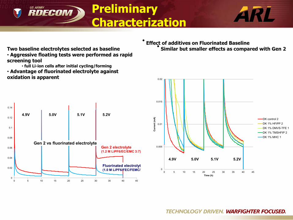
• Effect of additives on Fluorinated Baseline• Similar but smaller effects as compared with Gen 2
0
0.005
0.01
0.015
0.02
0 5 10 15 20 25 30 35 40 45
Cur
rent
(mA)
Time (h)
DK control 2DK 1% HFiPP 2DK 1% DMVS-TFE 1DK 1% TMSHFIP 2DK 1% MHC 1
4.9V 5.0V 5.1V 5.2V
0
0.02
0.04
0.06
0.08
0.1
0.12
0.14
0 5 10 15 20 25 30 35 40 45
Gen 2 vs fluorinated electrolyteGen 2 electrolyte(1.2 M LiPF6/EC/EMC 3:7)
Fluorinated electrolyt(1.0 M LiPF6/FEC/FEMC/
4.9V 5.2V5.1V5.0V
Two baseline electrolytes selected as baseline• Aggressive floating tests were performed as rapid screening tool
• full Li-ion cells after initial cycling/forming• Advantage of fluorinated electrolyte against oxidation is apparent
Preliminary Characterization

Effect of TMSHFiP on Impedance
0
5
10
15
20
25
30
35
40
0 20 40 60 80 100 120 140Rea
l im
peda
nce
, oh
ms
Test time, hours
1 kHz single-pulse impedance Control fluoro-electrolyteControl + 1v% TMSHFiP
Fully charged
Fully discharged
Fluoro-electrolyte with 1 vol% TMSHFiP additive
cycles with lower
impedance in bothcharged and discharged states.
1. TMSHFiP silane effective in Gen 2 carbonate and fluorinated electrolyte system.• Significantly reduces charge consumed by oxidation of Gen 2 carbonates• Observed decreased 1 kHz cycling impedance in fluorinated electrolyte
TMSHFiP additive: a descendant of the HFiPP phosphate-based electrolyte additive;MHC: a fluorinated carbonate
2. None of the propargyl-containing additives works• Too reactive for any electrolyte/LNMO combination• Stable radical may form shuttling species• DMVS-TFE very promising for Gen 2 carbonate systemC
oncl
usio
ns

Collaboration:
U.S. Army Research Laboratory (Dr. Kang Xu, Project team member) Brookhaven National Laboratory (Dr. Xiao-Qing Yang, Project team member) University of Texas - Austin (Prof. Arumugam Manthiram) Center of Nano-Materials, Argonne National Laboratory (Dr. Larry Curtiss)
Interactions:
• University of Rhode Island (Prof. Brett Lucht)• Jet Propulsion Laboratory (Dr. Marshall Smart)• Lawrence Berkeley National Laboratory (Dr. Vincent Battaglia)• Cell Analysis, Modeling, and Prototyping Facility (CAMP) (Dr. Andrew Jansen) • Material Engineering and Research Facility (MERF) (Dr. Gregory Krumdick)• Arkema (Dr. Ryan Dirkx)• NEI (Dr. Ganesh Skandan, Dr. Nader Hagh)
Collaboration and Coordination with Other Institutions
32

Argonne took a combined approach to tackle the voltage instability of electrolyte by developing the fluorinated carbonate-based electrolytes with intrinsic stability and the passivating cathode additive to afford a stable electrode/electrolyte interphase.
An effective probing tool was established for electrolyte oxidation stability by electrochemical floating test.
Fluorinated cyclic carbonates and fluorinated linear carbonates were synthesized and characterized and their electrochemical performance were evaluated in LNMO/graphite cells.
FEC and TF-PC based electrolyte have achieved superior capacity retention especially at elevated temperatures in 5-V LNMO/graphite cells. Post-test analysis showed that the fluorinated electrolytes are much more stable in both the liquid electrolyte phase and on the electrolyte/cathode interface.
Lithium compensation provides an efficient way to further improve the LNMO/graphite cells with a more stable fluorinated electrolytes.
LNMO/graphite cells with fluorinated electrolytes showed improved self-discharge at elevated temperature at fully charged state.
New electrolyte additives were synthesized and characterized; Live-formation of SEI by F-solvent was observed by in-situ electrochemical AFM.
New fluorinated sulfone-based electrolyte is in process.
Summary
33

For the rest of the FY15, we will continue to explore the fluorinated carbonate-based electrolytes to enable the high voltage high energy cells.
Synthesis and development of new additives tailored to stabilize the thermally stable fluorinated electrolyte TF-PC3.
Investigate the Li+ solvation in the fluorinated electrolytes by 2D-DOSY NMR. Electrode surface analysis using XPS and HR-TEM. Scientific write-up for publication in peer-reviewed journals.
For the rest of the FY15, we will initiate the fluorinated sulfone-based electrolyte study for high voltage high energy Li-ion cells.
DFT modeling of the electrochemical window of fluorinated sulfone. Synthesis and characterization of new fluorinated sulfone solvents. Evaluation of electrochemical performance.
Proposed Future Work
34

Technical Back-Up Slides
35

Other Benefits of Fluorinated ElectrolytesImproved wetting (contact angle measurement)
0
10
20
30
40
50
60
PolypropylenePlateCelgard 2325
Graphite
LNMO
OO
O
OO
O
OO
O
F
OO
O
CF3
HF2CCF2
OF2C
CF2H
OO
O
F
OO
O
CF3
OO
O
F
OO
O
CF3F3C
HF2CCF2
OF2C
CF2H
OO
O
F
OO
O
CF3F3C
HF2CCF2
OF2C
CF2H
Improves wetting!
Con
tact
Ang
le θ
(o) HVE-3
Gen 2
36
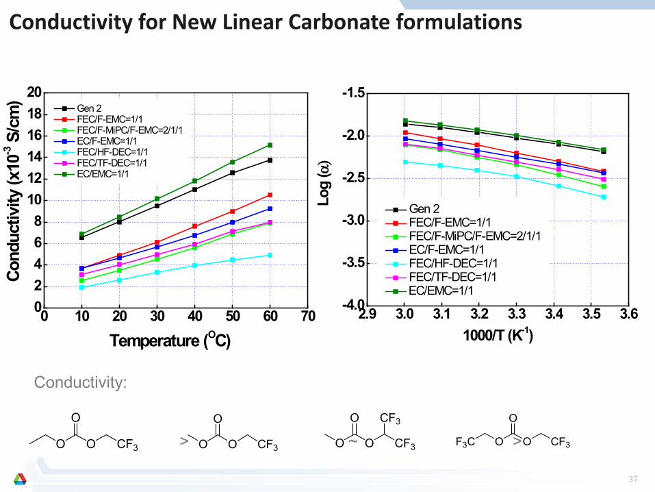
Conductivity:
> ~ >
0 10 20 30 40 50 60 7002468
101214161820
Gen 2 FEC/F-EMC=1/1 FEC/F-MiPC/F-EMC=2/1/1 EC/F-EMC=1/1 FEC/HF-DEC=1/1 FEC/TF-DEC=1/1 EC/EMC=1/1
Cond
uctiv
ity ( x
10-3 S
/cm
)
Temperature (OC)
Conductivity for New Linear Carbonate formulations
2.9 3.0 3.1 3.2 3.3 3.4 3.5 3.6-4.0
-3.5
-3.0
-2.5
-2.0
-1.5
Gen 2 FEC/F-EMC=1/1 FEC/F-MiPC/F-EMC=2/1/1 EC/F-EMC=1/1 FEC/HF-DEC=1/1 FEC/TF-DEC=1/1 EC/EMC=1/1
Log
(α)
1000/T (K-1)
O O
O
CF3 O O
O
CF3
CF3
O O
O
CF3 O O
O
CF3F3C
37