flying qualities of small general aviation airplanes i
TRANSCRIPT

I
__ DS-69-8FINAL REPORT
Contract FA 67WA-1752
FLYING QUALITIES OF SMALLGENERAL AVIATION AIRPLANES
Part I. The Influence of Dutch-roll Frequency,Dutch-roll Damping, and Dihedral Effect
P,7
%~
SPrepared for
FEDERAL AVIATION ADMINISTRATION[,:J-'L ". .: lA-'"1
,',), . • -. ' -Ie
ReProduced by pho
for LEAR INGHoU sEFodcre l Sclenhhc & Te. 'n
hIformation Spr ngfof& VTechi5a

j, FINAL REPORT
"I: FA 67WA-1752
1i DS-69-8
FLYING QUALITIES OF SMALLGENERAL AVIATION AIRPLAnES
Part 1. The Influence of Dutch-roll Fkequency,Dutch-roll Damping, and Dihedral 1'ffect
June 1969 A
Prepared byDavid R. EllisEdward Seckel
This report has been prepared by Princeton University for the AircraftDevelopment Service, Federal Aviation Administration, under ContractNo. FA-67WA-1752. The contents of this report reflect the views of
the contractor, who is responsible for the facts and the accuracy of thedata presented herein, and do not necessarily reflect the official viewsor policy of the FAA. This report does not constitute a standard, speci-fication or regulation.
PRINCETON UNIVERSITYPRINCETON, NEW JERSEY

ABSTRACT
As the first phase of a strAy of flight characteristics criteria for small
general aviation aircraft, experimnents were conducted with a variable -stability
flying simulator to determine the £inflence of Dutch-roll frequency, Dutch-roll
damping ratio, and dibedral effect. Other lateral-directional parameters were
held fixed at favorable levels. An ILS approach flown at 105 knots in simulated
moderate turbulence was the piloting task, The results are presented in a
generalized quantitative form useful to designers. High Dutch-roll frequency
(or high directional stability) and large dihedxal were found undesirable be-
cause of excessive yawing and rolling due to r~bulence. Low Dutch-roll fre-
quency led to poor heading control, large sidealilp excursions, and difficulty
in trimming the airplane, but low, -ven zero, dihe,-al did not interfere with
the approach task. Flying qualities were found to dte.riorate rapidly for
Dutch-roll damping ratio lower than one-tenth, but relativý0ely little was gained
by increasing it beyond that value.

TABLE OF CONTENTS
Page:
ABSTRACT i
TABLE OF CONTENTS ii
LIST OF TABLES i
SYMBOLS AND NOTATION iv
INTRODUCTION 1
LATERAL-DIRECTIONAL DYNAMICS AND FLYING QUALITIES -
A REVIEW 2
The Roll Mode 2The Dutch-roll Mode 3
Dutch-roll Excitation 4The Spiral Mode 7Parameters Related to Flying Qualities 8
EXPERIMEN:'TAL PROCEDURE 12
The Variable Stability Navion 13The Variables in the Phase I Experiment 15
Characteristics Held Constant 16The Turbulence Level 18The Piloting Task 19Data Acquisition 20Conduct of the Experiment 22
RESULTS AND DISCUSSION 23
Basic Results 23Interpretation of the Results from a Flying Qualities
Research Viewpoint 26Measures of Pilot Activity and Task Performance 31
CONCLUSIONS 32
REFERENCES 33
APPENDIX A-1
Lateral -Directional Equations and ApproximateResponse Factors A-i

111
LIST OF TABLES
Table
1 Coifiguration Parameter and Derivative Values
2 Iilot Opinion Rating Scale
LIST OF FIGURES
Figure
I Variable Stability Navion Flying Simulator (1967-1968 Configuration)
2 Cockpit Layout
3 Analog Computer Roll P.Rte and Yaw Rate Responses to AileronStep Inputs
4 Analog Computer Roll Rate and Yaw Rate Responses to RudderStep Inputs
5 Pilot Rating Contouxs, wd vs L•, Cd= 0. 10
6 Pilot Rating as a Function of Dutch Roll Damping Ratio, (d Constant
7 Pilot Rating Contours, iT , vs 13L
8 Constant Id[ Superimpcosed on Pilot Rating Contours, wd vs Ldd
9 Sample Test Data: Later hl Control and Rudder Control Deflections,Yaw Rate, and Localize. Oeviations. Simulated Turbulence.

iv
SYMBOLS AND NOTATION
I moment of inertia about the roll axis (slug-ft)x
I momen! of inertia about the pitch axis (slug-fta)Y
I moment of inertia about the yaw axis (slug-ft)z
I product of inertia (slug-ft2 )
iS instrument landing system
Kd/Kss Dutch-roll excitation parameter
L rolling moment (ft-lb)
Lp roll~damping T -p (rad /s ec per rad/ sec) •p L ( L ad ad/sec per radisec)
Lr roll due to yaw rate T Tr
x1LL dihdro l defeto y rT (rad/ sec 2 per rad)
L dihedral effect (rad/ aec per r i)
1 xL ieonefctvns - - (radi/sec2 per in)
ba I 66ax
N yawing moment (ft-lb)
"N yaw due to roll rate T _ (rad/sec per rad/sec)zlz N (rdreadlper pa/erca/sc
N yaw damping I 3N 2
N yawd n1- T N (rad/ sec per rad/ sec)
N directional stability (rad sec 2 per rad)z
ar N (rad/ sec2 per in)8a I S6a
z
N6 rudder effectiveness - N-(radlsec per in)
z1 \V\
71

v
V true airspeed (ft/ sec)
Sj -Ij
p roll rate (rad/sec)
S-r yaw rate (rad/sec)
rms root -mean -square
s Laplace transform operator s =0 C jw
sideslip angle (rad)
6a aileron stick deflection (in)
6 r rudder pedal deflection (in)
Dutch-roll damping ratio
'I• ratio of roll-to -sideslipd
07 real part of Laplace operator
a rms rolling moment disturbance per unit moment of inertia (IL due to gusts (rad/ sec 2 ) X
a rms yawing moment disturbance per unit moment of inertia (Idue to gusts (rad/ seca)
T roll mode time constant (see)rm
7 spiral mode time constant (sec)sp
CP bank angle (rad or deg)
w undamped natural frequency (rad/ sec)
Wd undamped natural Dutch .-roll frequency (rad/ sec)
COw undamped natural frequenry of - transfer function numerator
(0)d Dutch-roll real damping parameter

-1 -
INTRODUCTION
This report presents the results of the first phase of a systematic
study of the flying qualities of small general aviation aircraft. The program.
was inspired in part by the successful developmernt, over recent years, of
quantitative flying qualities criteria for piloted military airplanes, and it
employs many of the methods and tools, especially the variable stability
in-flight simulator, which proved to be useful in the research leading to
those results. The unique capabilities of the variable stability airplane
make it possible to design experiments in which certain characteristics
are varied while all others remain fixed. The effects of these variations
can then be examined in the context of a particular piloting task.
This phase of the study is focused upon Dutch-roll mode frequency
and damping, and effective dihedral, characteristics which heavily influence
the airplane designer's choice of tail size, tail length, and wing dihedral
angle. Roll response and spiral mode characteristics are held fixed at
favorable levels. The piloting task is an ILS approach in moderate turbu-
lence.
It should be noted that no attempt is made to simulate particular ex-
isting airplanes; rather, the range of each parameter is selected to be broad
enough to encompass both present design practice and possible variations due
to unconventional aerodynamics or artificial stability augmentation (yaw damp-
ing, for example). The variables in the experiments are handled in a manner
which accounts for inertia and speed effects as well as dimensions and geo-
metry, and the results are thus generally applicable to all reasonably small
airplanes. Very large airplanes or those with special mission requirements
(such as STOL operations) are not within-the scope of this study.
Later phases of the program w-ill consider variations in roll mode charac-
teristics, Dutch-roll excitation parameters, and longitudinal flying qualities.
LATERAL-DIRECTIONAL DYNAMICS AND FLYING QUALITIES - A REVIEW
Conventional subsonic airplanes normally exhibit three distinct natural
modes of motion involving the flight variables sideslip angle, heading (or yaw
angle), and bank angle. These lateral-directional motions, which differ from
each other in character and in time scale, are termed the roll mode, the Dutch-
roll mode, and the spiral mode.
The Roll Mode
I The roll mode appears to the pilot as a rapid increase in roll rate to asteady value following a lateral control deflection, or conversely, as the almost
immediate reduction of roll rate to zero when the lateral control is neutralized;
it is the mode which he deliberately induces to control bank angle. The charac-teristic time involved is termed the roll mode time constant, T" , and physically
r mit represents the time required for the airplane to reach 63% of the ultimate
steady-state roll rate following an abrupt step-like lateral control surface de-flection (or a step-like rolling moment from turbulence). Large roll damping
leads to small time constants, a quarter or even a tenth of a second being typical
values for general aviation aircraft. In fact, experiments show that the time
constant must be small (less than a second) if the airplane is to be precisely
controlled. It is thus an important flying qualities parameter; the roll modecharacteristics selected for the present experiments are discussed in the sec-
tion on experimental procedure.

-3-
The Dutch-roll Mode
The lateral-directional motion known as the Dutch-roll is the oscillation
involving simultaneous rolling, yawing, and sideslipping which may be observed
following a gust encounter, or following any control application which results in
sideslipping (such as uncoordinated" use of aileron and rudder in a turn entry).
It is not deliberately used by the pilot in the sense that he uses the roll mode
for banking and the longitudinal short-period mode for pitching, but nonetheless
it must be considered by the designer because the typical lightly damped Dutch-
roll motions can, under some circumstances, seriously interfere with precise
control of the flight path.
The oscillatory character and time scale of the mode are closely asso-
ciated with the yawing moments which arise due to sideslip - the directional
stability of the airplane. The frequency of the oscillation is, in fact, given
approximately by the square root of the static directional stability parameter,
N Small inertia about the yaw axis and/or large aerodynamic restoring
moments due to sideslip lead to large values for N, , and hence to high fre-
quency (or, alternatively, short period) motions, and vice versa. The aero-
dynamic portion involves air density and airspeed - low altitude and higher
speeds result in higher frequency - and airplane geometry. This last factor
is the one over which the designer has a measure of control, since it includes
tail size and tail length; higher frequency results if either is increased.
The damping of the oscillation - the characteristic decrease of amplitude
with time - is due primarily to the yawing deceleration resulting from yaw rate,
N . Aerodynamic moments which resist yawing are provided mainly by thervertical tail, a rotary motion about the yaw axis resulting in an increment of
angle of attack of the vertical tail proportional to yaw rate. The resultant
Np is an example of a "dimensional" stability derivative. Physically, thesederivatives represent acceleration per unit of the variable involved, in this caseyawing acceleration per unit of sideslip angle. They are the coefficients in thecquations of motion presented in the Appendix. It should be noted that they in-volve the mass or moment of inertia, flight condition, and airplane size andgeometry. A textbook such as Reference I should be consulted for details onestimation of these derivatives,

-4-
moment is a function of tail area and shape and the square of tail length, so
the designer has a measure of control over yaw damping. The effect of inertia
about the yaw axis works against the aerodynamic damping moments, since
once the motion is started the inert'ia tends to make it persiat. Secondary in-
fluences on damping arise from lateral resistance to sideslip (Y I V), roll
due to sideslip (La), yaw due to roll rate (N ), roll damping (L ), and roll
due to yaw rate (Lr); but generally the effects of these derivatives are smallr
compared to the imfluerce of N rrIn this report the level of damping is measured in terms of a damping
ratio, C, which compares the actual damping available to that just sufficient
* o to prevent an oscillation from occurring. Thus no damping is signified by
S0, and negative C indicates an unstable motion; • = I indicates no
oscillatory character and a system with 4 = 0. 7 is considered heavily
damped since it exhibits virtually no overshoot of the steady-state value in
its response to a step input. By comparison, the Dutch-roll mode is almost
always lightly damped in small general aviation aircraft, • 0. 1 being not
unusual.
Dutch-roll Excitation
In general, whenever yawing or rolling moments or side forces are
applied to the airplane the Dutch-roll will be excited. The two sources of
such forces and moments are turbulence and control deflet.tions; the factors
influencing the size and nature of the excitation are discussed in this
section.
(A) Excitation from Turbulence. An airplane flying in random turbu-
lenc . is subjected to a gust field which may be resolved into side gust, verti-
cal gust, and fore-and-aft gust components. It is useful te think of these

gusts as -causing small increments in the flight variables: a side gust, for
example, prod'uces a sideslip, a vertical gust a change in angle of attack.
These changes in the flow field produce increme-ntal aerodynamic loads on
the airplane and the resultant forces and moments cause rolling, yawing,
and pitching accelerations.
The point to be emphasized is that the response of the airplane, that
is, the size of the acceleration caused by a gust, is indicated by the size
of the corresponding stability derivative. A large value for the dihedral
effect, L , for example, will lead to large roll accelerations due to side
gusts; and large directional stability, indicated by a large value for N
(or high Dutch-roll frequency), will lead to large yawing accelerations.
Since the dimensional derivatives are ratios between aerodynamic force "
(or moment) and mass (or moment of inertia), it is apparent that the gust
response of the airplane is :-fected by both its aerodynamic characteristics
and its inertia.
Thus the stability derivatives that determine the basic dynamic re-
sponse characteristics of the airplane also determine the mann-r and extent
to which the airplane will be disturbed by turbulence. In general, the de-
signer iz faced with the need to compromise, because aerodynamic charac-
teristics which seeL.. desirable for flight in smooth air, such as very large
directional stability, may lead to undesirable characteristics for flight in
turbulence.
(B) Excitation from Lateral Control Deflection. Yawing moments
which arise from use of the lateral control are an important, and particularly
undesirable, source of Dutch-roll excitation - undesirable because the pilot

depends so heavily upon precise control of bank angle for turning, and any
signii.cant yawing and rolling oscillfations will interfere with accurate con-
trol of the flight path. At best, some pilot compensation in terms of Con-
scious attempts to stop the orcillations or careful aileron-rudder coordina-
tion to prevent them from starting will be required; at worst, the pilot's
attempts to stop the oscillations with his roll control may only aggravate
them, resulting in an unstable pilot-airframe system.
The important factorc here are yaw due to lateral control deflec-
tion N ,. and yaw due to roll rate, N . The first makes its effect feltp
at the instant of control deflection, while the second comes into play as
soon as the roll rate becomes significant. Both are usually in the "ad-
verse" sense, a roll to the right resulting in yaw to the left. It is im-
portant to note that simply providing ailerons (or some other lateral con-
trol device) which give zero adverse yaw will not completely remove the
Dutch-roll excitation effects of lateral control use, because the yawing
fTom roll rate (N,) factor remains. I Since N is influenced mainly
by wing geometry it is not much under the control of the stability and
control engineer.
The parameters which serve as measures of this lateral-controlexcitation of the Dutch-roll mode are the ratios wcn1d and Kd IKss
Although these are not treated as variables in this phase of the program.
they play an important role in the design of the experiments and in the in-
terpretation of the results. They are discussed in the section entitled
"Parameters Related to Flying Qualities."
1 There will also be a small residual Dutch-roll even if both N arnd N6a
are zero. It is caused by sideslip due to bank, and is usually small enoughto be ignored.

-7-
(C) Excitation from Rudder Deflection. Rudder deilections can, of
course, excite the Dutch-roll by producing yawing accelerations, And in fact
a vigorous right-left-neutral (or vice versa) rudder input is an excellent way
of obtaining a Dutch-roll oscillation for purposes of observation. Once the
rudder has produced yaw and sideslip, the restoring tendency of the direc -
tional stability (Ne) and the coupling effects of dihedral (La) and roll
due to yaw (L ) come into play to start the motion. This sort of excita-r
tion can and does occur when the pilot attempts to make heading corrections
with rudder alone - there will be some transient yawing oscillations before
the airplane settles down on the new heading.
The Spiral Mode
In contrast to the roll mode, the spiral mode is (usually) a slow-
acting motion which is often unstable. The pilot recognizes it as a tendency
for bank angle and yaw rate to increase for the unstable case (or decrease
for the stable case) if the airplane is left unattended in a wing-down attitude.
The characteristic times are long - the time required for the bank angle
or yaw rate to double or halve is usually more than ten seconids - and
the mode will go unnoticed if the pilot is actively controlling bank angle.
However, the spiral has a history of association with accidents involving
noninstrumernt-rated pilots flying in bad weather, and unusually quick di-
vergence m~ght add materially to the workload of even the experienced in-
strument pilot, so the mode is not a trivial one. Detailed consideration of
the stability derivatives involved will be deferred to a later phase of the pro-
gram, but a discussion of the treatment of the spiral in the present Dutch-
roll research is included in the section on experimental procedure.

-; -8-
Parameters Related to Lying Qualities
The previous sections have dealt with the character of lateral-direc-
tional dynamics, especially the Dutch-roll oscillation, and the means by which
these dynamic modes are excited. The purpose of this section is to discuss
factors wh: -. are recognized as being related to the study of flying qualities
as contrasted with airframe-only dynamics.
(A) Dutch-roll Mode. As previously indicated, the Dutch-roll mode
can, under some circumstances, seriously interfere with precise control cf
the airplane. The pilot can directly sense the frequency (w ) of the motiond
and the damping (Cd or CdWd), and since they determine the time scale and
the persistence of the oscillation they are important flying qualities para-
meters. They have a bearing upon whether the motion will be so objection-
able as to require pilot attention to suppress it (perhaps because of low damp-
ing, or very low frequency associated with low directional stability) and whether
he can indeed do so (very high frequencies, for example, might require very
fast and precise action with the rudder). As noted previously, the Dutch-roll
frequency is closely related to the yawing disturbances from turbulence through
the Jerivative N 9, a higher frequency leading to larger turbulence response.
This is obviously an important factor to the pilot.
Other features of the basic Dutch-roll dynamics may be important to
the flying qualities, the most prominent probably being the ratio known as
Ic/ • 1d, the ratio of bank angle to sideslip in the natural Dutch-roll oscilla-
tion. Large values of Icp/ Jl represent Dutch-roll modes which have pre-d
dominantly rolling motions; small dy, jd represents a yawing-type motion.
For tyrical light airplanes the ratio is about unity, but very high performance
airplanes, especially those with swept wings, may have values of ten or more.
Large values of 1c3 0 13, usually associated with large dihedral, have long
been held to be undesirable and to require more favorable values of other

-9-
parameters such as damping ratio. Again, this reflects the need for precise
control over bank angle in order to accurately control the flight path.
The phasing of the bank and sideslip in the Dutch-roll is sometimes
important. This is the macter of whether or not the motion is positive bank
with positive sidealip (right-wing down with nose-left, the normal case), and
it is a factor in situations whire Dutch-ro1l ercitation from the lateral con-
trol tends to lead to pilot-induced instability.
(B) Roll Response to Lateral Control. The response of the airplane
to lateral control inputs is of primary importance in the study of lateral-
directional flying qualities because of the pilot's great dependence on pre-
cise bank angle control. He must be able to achieve a desired bank without
overshooting and without having to cope with excessive interference from
Dutch-roll excitation if he is to accurately control the flight path.
The roll mode is central to this matter. As mentioned previously,
this is the primary mode involved in banking and turning, and the relevant
flying qualities parameter is the time constant, T . If this time constantrm
is long, say much over one second, the pilot tends to have trouble reaching
a desired bank angle without overshooting and needing to make several small
corrective inputs.
The Dutch-roll component in the roll response needs to be considered
in some detail. Use of lateral control will excite the Dutch-roll mode due to
the presence of yaw from the control itself (N a) and from roll rate (N p), and
the total roll response will be the sum of the roll mode and the roll component
of the Dutch-roll. A convenient parameter used to indicate the degree of ex-
citation is the ratio K d/ K S, which expresses the magnitude of the roll-rate
due to the Dutch-roll mode at the instant of an abrupt step-like lateral con-
trol input compared to the steady-state roll rate. This is illustrated on the
following page:

-10-
(
RoIl Dutch-roll damping envskpe1*0
Ke -Stoody-SstetMAI rahe
0t --.- ----
with Dutcho-roll excitation
ssmode is not excited by use cJ the lateral control, which is a desirable feature.This is not to irply that the Dutch-roll no longer exists, but rather that a
lateral control input does not give rise to moments which excite it. If Kd/ Ks
is about unity the roll rate will reach almost zero on the first downswing, and
the bank-angie response will have a stair-step nature. Large values of the
ratio - greater than unity - are indicative of roll-rate reversal, clearly an un-desirable response to a step input.
Another parameter discassed widely in the literature and associated
with Dutch-roll excitation in the roll response is the ratio w 1[wd. Here wdis the true Dutch-roll natural frequency and w is a constant occurring in the
0rtransfer function of roll response to lateral control. It is physically identifi-able as the frequency of a special Dutch-roll which would result if the wingscotid be held exactly level with the lateral control so that the oscillation would

have only yawing and sideslipping motions. In general, this particular kind-of
Dutch -roll would differ in both damping and frequency from the real motion be -S cause of the yawing momnents from the lateral control (N ) and because of the
lack of rolling. At any rate, the frequency ratio w •1• is indicative of whetherCP d
the frequency of the pilot-airframe system in a roll-tracking situation will be
higher or lower than the basic airplane Dutch-roll frequency. It turns out that
if W /wd is unity or less, the pilot-airframe system will be stable, but if the
ratio is greater than one and the basic airplane damping is low, the system
may exhibit poor stability, or mzy even be unstable. In this case the pilot,
attempting to control bank angle, actually drives the system into unstable t
oscillations.
(C) Individual Stability Derivatives. The static stabilities 14 and L
aze important in their own right aside from the ways in which they influence
the dynamic response-and other parameters mentioned above. The associa.-
tion of N with the yawing response to turbulence was made in part (A) of this
section and the dihedral, L13 , is similarly important. Large dihedral leads
to large rolling disturbances from side gusts and these are certainly of con-
cern to the pilot. (It might be noted here that the disturbance effects asso-
ciated with other derivatives such as L , N P Np, Y are generally muchp r
smaller than N and L effects, and unless the former happen to be very
large compared to N and L A the pilot doesn't usually single them out as
important turbulence response factors.)
The pilot also senses N and L directly when performing steady
sideslips. Large N, gives a "stiff" airplane, one resistant to sideslipping,
while small N results in an airplane which is "weak" directionally and
which sideqlips readily. The normal sense of the dihedral, L13, requires
that the pilot cross control - right aileron and left rudder for a slip to the
right, for example - in order to hold a steady sideslip. It also figures

p..,
-12- .
largely in the ability of the pilot to roll the airplane with the rudder only, a
matter of some importance if lateral control is poor at angles of attack near
or beyond the stalling angle.
(D) Control Effectiveness. Control effectiveness, measured by roll
acceleration per unit of lateral control, L, and yaw acceleration per unit
of yaw control, Nsr, are important flying qualities parameters, although they
do not alter the characteristic frequencies, dr.mping, or time constants of the
lateral-directional modes. From the pilot's standpoint the control must seem
neither too sensitive nor too sluggish. However, this cannot be studied inde-
pendently of the basic dynamic characteristics of the airplane; the optimum
roll sensitivity (Lsa), for example, is closely related to the value of the roll6a
mode time constant. Likewise, rudder effectiveness must be appropriate forthe existing levels of static directional stability and yaw damping.
EXPERIMENTAL PROCEDURE
An experimental approach to flying qualities research almost always
involves the use of some form of simulator as a substitute for the actual air-
plane. Cost considerations aside, the researcher often needs to explore a
wide range of parameters or change one characteristic without altering others
at the same time. This obviously would be difficult, if not impossible, to do
even if he were allowed to build a fleet of specially-configured airplanes -
hence the research simulator. The form depends upon the importance and
complexity of the problem, and ranges from comparatively primitive fixed
chair-stick-and-pedals with voltmeters for instruments, to moving-.base
devices with several degrees of freedom and sophisticated visual displays,
and finally to the variable stability airplane, a true flying simulator. This
last-mentioned device offers the least compromise with reality, since the
pilot is in ar actual flight environment. Such a machine was used for the
experiments in this program.

-13-
The Variable Stability Navion
Variable stability (or better, variable response) airplanes come in
several sizes and degrees of system complexity, but in genaral they all pro-
vide for in-flight variation of the static and dynamic stability paranmeters over
a wide range and thus have "variable flying qualities." The variable response
airplane used for this program was derived from a Nort.h American Navion
airframe and is pictured in Figures 1 and 2. The machine and its control
system are described in detail in References 2 and 3, but a short review of 4
the principle of operation may be helpful in understanding the experiments.
The most basic modification of the airplane is the provision for power-
actuated control surfaces. Electro-mechanical servos drive the ailerons, -
rudder, and elevator, with a fast-acting hydraulic servo moving the flap.
The operating signal for each servo is a sum of the signals from the evalua-
tion pilot's controls (which are not connected mechanically to the surfaces
and which produce only electrical signals proportional to deflection) and
sensors which measure the flight variables. For example, the aileron
servos may receive a signal summed from a roll control command, plus
signals proportional to sideslip angle from a yaw vane, and roll rate and
yaw rate from gyros. The last three signals are the ones which change the
airplane's basic roll response characteristics by cauasing it to accelerate in
roll more (or less) than the basic Navion does for the same roll rate, the
same sideslip angle, or the same yaw rate. Similar "feedbacks" are applied
to the rudder to change the yawing response to sideslip, yaw rate, and roll
rate; to the elevator to change the angle of attack and pitch-rate response;
and to the flap to alter the lift response to changes in angle of attack. Thus
the dynamic response characteristics of the basic Navion are changed by aug-
menting or diminishing the individual static and dynamic stability factors -
the stability derivatives mentioned in the previous section. The size of each
feedback signal is controllable from the cockpit so that the simulator may be
adjusted in flight.

-14-
in addition to the signals from the control stick, rudder pedals, and
the sensors, tape-recorded signals representing turbulence are sent to the
se:'vos and produce the disturbances of flight in rough air, which are appro-
priate to the airplane being simulated. An airplane with large dihedral effect,
for example, will be simulated with appropriately large rolling disturbances
due to side gusts. The overall level of the artificial turbulence can be ad-
justed to produce severity ranging from zero, or no disturbance, through
"heavy moderate, " a level which might be experienced in the vicinity of a
squall line or in the lee of a mountain range. The turbulence signals have
frequency characteristics which are like those of the turbulent atmosphere:
strong gusts have relatively low frequency of occurrence compared to smaller
gusts and as the frequency increases beyond a certain level the gust intensity
diminishes until, at very high frequencies, the amplitude is very small. The
influence of turbulence on flying qualities is of such fundamental importance
that it just cannot be avoided or treated casually, and thus the capability for
simulating the effects is one of the more important features of the variable
stability Navion.
It is imperative to know exactly what is being simulated, and urnfor-
tunately the desired configurations can be set ordly approximately by ground
calibration. For this reason an in-flight calibration called "configuration
matching" is carried out to determine the exact variable stability system
control settings needed to produce the desired response characteristics.
The process involves setting up an analog computer representation of the
desired airplane and then ad:usting the flying simulator until its response
matches that of the ground-based computer. In practice, the control de-
flections of the simulator are sent to the computer via telemetry and thus
the pilot flies the computer airplane and the real airplane simultaneously;
the motions of the airplane likewise are telemetered to the ground and com-
pared with the computer output. Special matching maneuvers are performed
and the variable stability system is adjusted until the responses agree closely,

-15-
The Variables in the Phase I Experiment
The variables selected for the first phase of this study of general aviation
airplane flying qualities were Dutch-roll frequency (wd), Dutch-roll damping ratio
(Cd), and dihedral effect (L ). As indicated in the previous section, these are
all important lateral-directional flying qualities parameters and are to a large
degree within the control of the designer. It was felt that knowledge of the effects
of these three quantities would be a useful fram-.mrk within which to study Dutch-
roll excitation and roll-damping requirements in a later phase. The. range of
each of the variables is indicated below:
(A) Dutch-roll Frequency. This variable ranged from 1.3 radians per
second to 3. 0 radians per second, corresponding to Dutch-roll periods of 4. 8
seconds and 2. 1 seconds respectively. Most light airplanes fall within these
extremes. Intermediate configurations with wd = 1.8 radians per second and
2.3 radians per second were also tested. For reference, the basic Navion fre-
quency is 2. 2 radians per second at normal weight and a speed of 105 knots.
(B) Dutch-roll Damping Ratio. The tests were conducted at three dis-
crete damping ratios: d = 0. 05, d = 0. 10, and Cd = 0.40. The first is definitelyddd
"light damping, " but C d = 0.10 is fairly typical of small airplanes without artifi-
cial yaw damping (Cd 0. 15 for basic Navion). The high damping ratio, Cd = 0.40,
is larger than normal aerodynamic configurations are likely to pi ovide. It was
selected in order to explore the possible benefits of additional yaw damping,
either aerodynamic or artificial in nature. Most of the testing was carried out
with Cd = 0.10.
(C) Dihedral Effect. Dihedral effect ranging from zero to moderately
high (Lf = -32) was tested. (An unfortunate sign convention may be noted here:
normal, or "positive, " dihedral effect, signifying a roll to the left for a side-
slip to the right, is associated with negative values of the derivative L
i4

IJ
S~-16-
All con-15gur--ions tested 1-d di--edrA in the normal sense..) For refe-rzCe.
the basic N-aion dihtedra! tifect is aboac L =-16 at a speed of ICS I=W.s am&
-urmnal 8eigt.
It should be noted that the roll coerol se'sitivfty (f ad r6e-r
sensitiity (N 6 ) were mot considered to be -ariables in the experiments. bu
neiher were they fixed.. T-e evleation piloes were asked to use 0:c levels
wh5ch they consideared optim•muz for cach coofigmiaion. This was dome to pre-
vent the results from. being influenced by tbe use of co---rols wbich were too
sensitive or too sluggish for the dySnarnics bcing tes-zed.
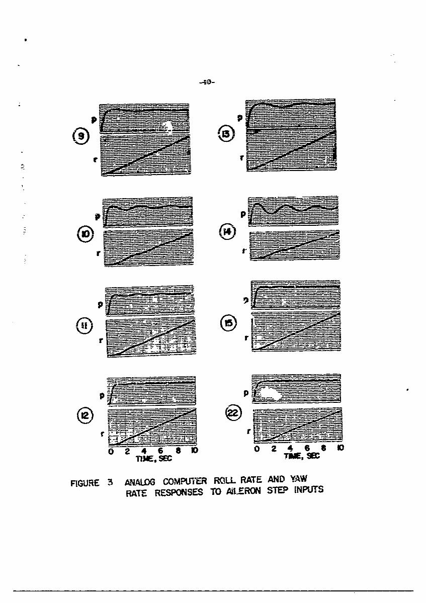
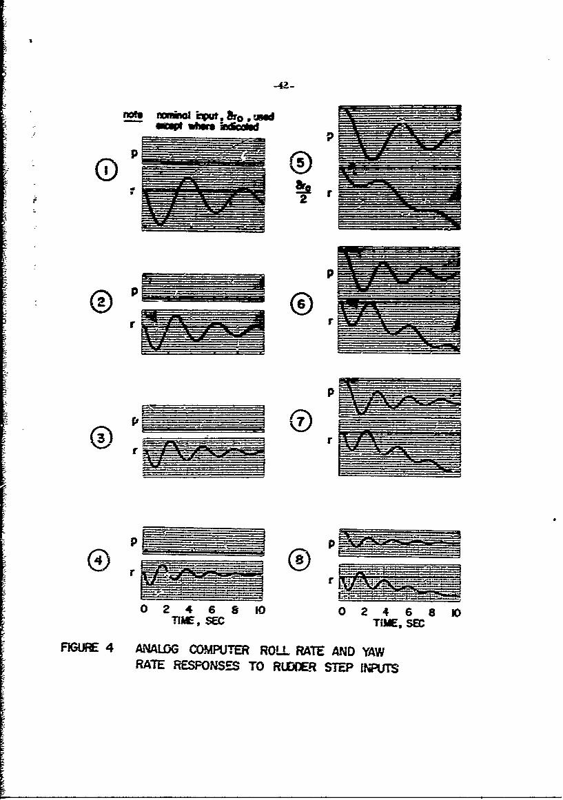
For reference purposes, a list of the config-rations ard their para.-
metters is iLcuded as Table 1. Time histcries of the roll rate zad yaw ra~tt
response- of each configuratr-ion to a sten lateral con•trol deflzction ar.i a _-tp
rudder deflection are sho-n in Figures 3 and 4 raspectively..
Characteristics Held. Constant
The variz-ble respopose capabilities of the flying -3iluiator were used
to hold other lateral-directional. characteristics fixed while the effects of the
specific test rariables were investigated. These ficed characteristics were
the following:
(A) Roll Mode. The roll .-mrode was given a time constant (time to
reach 63% of the steady roll rate following a lateral control step input) equal
to one-quarter of a second. This is a value which permits very satisfactory
controi of bank angle -.vithout overshooting, and selection of a cornmatible con-
trol sensitivity is not difficult or critical.
(B) Dutch-roll Mode Excitation. This was held to a low, noninterfer-
ing level as measured by the parameters K I K and w /w . Referring tod ss q) d
Table 1. it is seen that K.IK for most cases is less than 0.Z, and w I Wce ss
is u-nity or less, both conditions leading to a good pilot-airframe system as
far as roll control is concerned. The notable exceptions are Conrliguration 14

2ý3,~~ 0..L- -6
is czearr- -bthercl1-resrYcse fli2 hi-f-US 1Oh i 3..
G~~~ci14 beem atzaEea F iozsl~ (Rmeriewees 20 2-T- 3) aV3 il bag
be=~ sbo= :Bat 0a*CoS atre ecCCr~tad Wab 21S ercesaire tueeQrespmmse-
ace to- d~eral" amd == ZIt -excessive Dc-l x!Ze CaG5SgZaiGm 29
haZs a d3p---r:g zrztio Saffi-cie=11y large- to r-eclode p;1Ctiz FTCbCS ;" ZO!1 6=
to BE IB K he were f=C10de6 in rder .~ to,.-eta=- a co:=t~eie set off C0Cffgt=a-
tmo-S whicb 2:2d te- c~e i a rzceviyssi ' a~d W-i±- WSCB a wa's d'esired to
c602=re re5sclc
Z35-eCp IFor the tw ccMigratiionS rcted 25=C the ti±bso ies ia
goo roll re-spase to step aile~rom irzms, a reCnirC=:e~. for Proper i~terprma-
rion Cal i.b ef Eecrs of Dt:cB -rCII excizanioz Z3:Sirg freczi ~ ý(--N
jC Spoir-al Iredle.. !ie s.-iza! rmode was a4edto Zbe necir21 - that is,
rfihrcan-ergema =o- ciwerge= - for 2!i co=:5gnat2io--s. Tbis U'as -:One to Pre-
w-e-- the nic-de firo=i possbil-y fe wiozb tize evaIC~ation- 0-- the ZCstC Varables,
Siz-Xe == Con-rolling ft -.ocud i'ae res--fed in~ eja-mmely ocick com-ergemce f&or
the ligh- dihedral, low freae~eny arplaoes -n e-ie-ma abvergecice for the zero-
dihediral, high frequency -.-achines..
dhis a sinent of ibe spi2ral ;6as do.-e largely wfth the deriv~ativre L r
the roll due to yaw rate, or =overbuxnkidzg terndency, ' because other derivratives
whisch are irnpor-tant. to the mode, L N and N are either indevezzen!et~ra
bles thernselves (L ) or are closely associated with the imdepen-dent v-ziables
(N, with xd and Nwith ~d*This leads to unrealistically large valms of Lp3 d r
'or soime configurations (for exaraiple, T = 18.94 for Configuration 29 -which
ha sL 1-6 2 w 1. 3, "= 0. 4, compared to the bas-ic Na-.-ion L ~2). On0d *ýd r
the other hand, it leads to the requirement that L rb-- zero for the zero-dihedral
configurations, and this is not physically possible for finite wing-span, normally-
configured airplanes.
t~e effe-t aff tbase -- re2KlistiEc vwalies o2f cco the roll moder
is riH, arid the effect am th-e Th~tcb-roll is sba;L With L = 0 the DUZtch-roil
rr
-e!::a zrid the roll-to sde~zlii ratio =omd be- abaci four-t--e~ffs imstead of zeroas estd..~cierae fee~~, erate dihedrzI cccdigarations WOUld cha~gC
bar-Dr at ali with L = Z. wbile redccic L f-on g8urao ZGr r~z~29c~idhzx~ther~l4 -sdslip ratio frontkiI to.V I-:;/
0:J Oter Ccs~ara.. Ofther camstants ar, t-he side-acceleration deriva-
tire T 1 / V zan tbe r~zcr X/ IV.. ~eSide -1orce ch -act eristic s off the ~wo
cam~ox be- vzrid b~t t~el a-re typic.0l of dais class off airpl-ane.. h experi-
=e* W-er- tflon a2 CriM. airs~ead c~ -r5 R6 =Ots..
aon act to rdemr eiletio~., 1- r was tr-ade ecoal to zero.. it is hard
to assESM a MpcV O=eroG -ale tO tBD-i defriatilxe.. z=6 tfhe effect; are likely
to be SnaII.
Yw'W Jue to lateral comraral, Naa was rn-ade zero for all con-figurations
ian order to kee-c Dz-.cbn-roUl excitati-m .o a- low leveL Thi:,s derivative ecters
:--w b mh z and CK I K _ and %ill be trealted as a rari-able im az phase
ofC the Pregram-.
Fin.aHiy. the ionmgitudizzal characteristics weze held fixed at basic Navicn.
levels.
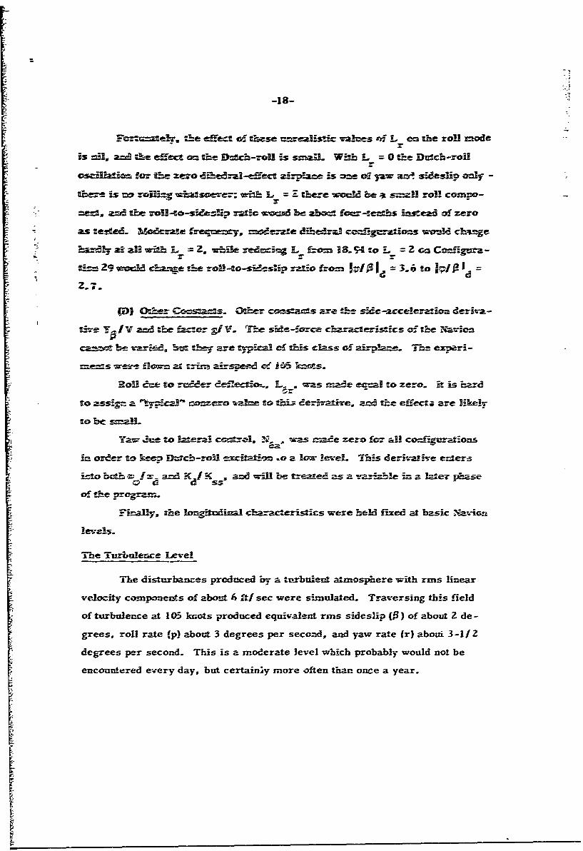
The Turbulence L~evel
ITse disturbances produced by a tprbtilent atmosphere with rins linear
velocity coinponeztts of about 6 ft/ sec were simulat ed. Traversing this field
of turbulen~ce at 105 knots produced equivalent rms side slip (j3) of about Z de -
grees, roll rate (p) about 3 degrees per seco~nd, and yaw rate (r) aboui 3 -1/2
degrees peer second. This is a moderate level which probably would not be
encountered ev..ery day, but certairi~y more offten thar. once a year.

-19-
The Ploting Task
An IIS approach in turbulence was selected as the piloting task for the
flight experiments. The factors involved in such a selection are many in num-
ber, often involving operational considerations or problem, in evaluating re-
sults. The ILS approach waa picked on its merits as a realistic, demanding
task from which measures of performance could be obtained.
The matter of realism involved the questions of whether or not the task.
was one that an airplane of this class might be expected to perfonr., and whether
or not the flying qualities of the airplane were important to task performance.
Tc enlarge upon this point, all airplanes spend a large proportion of their total
time in cruising flight, but if the pilot is not engaged in tight control of heading
or bank angle, one cannot make much of a case for needing good Dctch-roll
d=amping, good roll response or good behavior in turbulence (except perhaps
fromn the standpoint of riding comfort); the task is one of keeping the airplane
generally right side up and pointed in "he desired general direction ýnd is
esse-tiall-y '-open-loop" as far as pDloting is concerned. Small perturbations
on top of the gross flight path are not of m.uch consequence.
As the pilot is requ:ired to control the machine more and more precisely -
to hold the wing' level, fly a particular heading, track a VOR radial, then do all
oi these things by reference only to instruments - he must not only be more pro-
ficient, but such things as adequate damping, good control response,. and good
behavior in turbutlence become more important.
ThiS reasoning led Zo the selection of the instrument approach in turbu-
lence as a demanding task which primarily involves the flying qualities of the
airplane. It requires precise control of the airplane and presents an inherently
high workload, so that any need for the pilot to compensate for poor flying quali-
ties is particularly undesirable. From an experimental standpoint, each approach

is of sufficient length to permit a good evaluation of a configuratiCn, and it is
possible to measure and record task performance in terms of localizer and
glide slope deviations. To summarize: for the ILS approach, task per-for-
mance was measurable, the highest level of tracking and precise control of
the airplane were required, and the workload was inherently high enough so
that any requirement for the pilot to compensate for poor flying qualities was
undesirable.
_ Standard gyro horizon, directional gyro, and ILS cross-pointer infor-
mation without flight director or horizontal situation displays were used. This
was felt to be Itpical of equipment used in general aviation instrument Plying,
and at least representative of back-up eqr.viment for aircraft with more sov'his-
ticated instrumentation.
The foregoiag should not be taken to imply that other tasks might not be
important or infor-mative. The visual portion of the final approach and the
flare and touchdown, perhaps in the presence of wind-shear and/or crosswinds,
represents a total task with its own high demands on contrcl :esponse and con-
trol power and behavior in t.urbulence; this is indeed worthy of investigation but
it presents problems of performance measurenment and evaluation and simula-
tion which are beyond existing capabilities. Simpler tasks, such as precision
heading tracking which is an important part of the overall ILS approach, are
indeed often informative (and in fact such tests are referred to later in the re-
port), but lack the validity which zomes from having the pilot perform the whole
task. Maneuvers involving flight directror tracking also are potentially useful in
examining certain aspects of the overall piloting prcblem.
Data Acquisition
(A) Pilot Ratings. The primary data in a flying qualities study such as
this one consist of numerical ratings and comments supplied by pilots who are
trained and experienced in the art of evaluating flight characteristics. The

-21-
revised rating scale shown in Table 2 (the so-called Cooper-Harper scale from
Reference 3) was used, and it represents a usef U conversion of verbal descrip-
tion; to numlbert. It may be noted that the pilot is being asked to rate tŽe air-
plane on the basis of how much he must compensate for uudesirable character-
istics - characteristics, for example, which require him to anticipate or lead
motions, or produce intentional lag-, or which require too much control activity.
Even if the actual l evel of task performance stays uufformly high as the flying
qualities get worse (a situation which is not unusual up to the point where the
pilot's capabilities are saturated), the pilot can sense that he is working harder.
He is being asked, in other worde, to measure and report his own workload,
and3 a trained test pilot can do this very effectively.
The comments which accompany the ratings are extremely important,
because with them the pilot indicates just what it is about a configuration that
is bothering him, and it is necessary to know this for proper interpretation of
the results. In this program the pilots were asked to comment specifically on
control response, control techniques, turbulence response, and airplane dy-
narmic characteristics.
It must be emphasized that results in terms of ratings and comments
should be viewed in the context cf the task flown; they may or may not be di-
rectly applicable to other situations. In this regard, it is usual to attempt to
pick a "critical task" so that flying qualities criteria established for that situa-
tion will result in airplane flight characteristics which are also satisfactory
in other flight regimes. If that is not possible, then testing must be carried
out for at least the more important flight regimes.
Four evaluation pilots were used in this program, three of whom were
ATR -rated, the other Commercial-Instrument rated. Two had engineering
flight testing backgrounds and prior experience in flying qualities evaluation;
the other two were relatively inexperienced in this respect but were given
special briefings and training in the variable -stability airplane. All had

-22-
extensive experience in instrument flying and in the class of airplane considered
, in this program.
Before each flight the pilot was briefed on the task, the rating scale, and
the type of comments needed. in the air, ratings and comments were given and
recorded immediately fo'llowing each approach.
(B) Other Data. Measurements of airplane motions, pilot activity, and
task performance were relayed to the ground via telemetry and recorded on
magnetic tape. Angular rates in yaw and roll were the most important items
in the first category; the second category, pilot activity, involved stick and
rudder pedal movements; localizer and glide slope deviations were the mea-
sures of task performance.
Conduct of the Experiment
The ILS approaches were flown at Mercer County Airport, Trenton,
New Jersey. The system there is standard with a 3. 0 glideslope and 4.5
nautical mile separation between outer and middle marker beacons, giving
about Z. 5 minutes between markers at the test speed of 105 knots. A race-
course pattern involving an outbound track parallel to the final-approach
course and a turn to intercept the localizer about one milk .eyond the outer
marker was substituted for the standard procedure turn to expedite testing.
The airplane with its simulated stability and response characteristics,
but without artificial turbulence, was handed over to the evaluation pilot abeam
the outer marker, outbound, for familiarization and selection of optimum L6a
and N6r. After the turn-around and upon intercepting the localizer the turbu-
lence was turned on; data recording was begun at the outer marker and continued
down to the middle marker, where the telemetry signal usually became unreliable.
At a point past the middle marker the evaluation pilot was instructed to raise the
hood and continue the approach down to the runway threshold, where control was
taken back by the safety pilot (left seat, standard mechanical controls) for the
pull-up and climbing turn back to the outbound course.
:-
-Z3 -
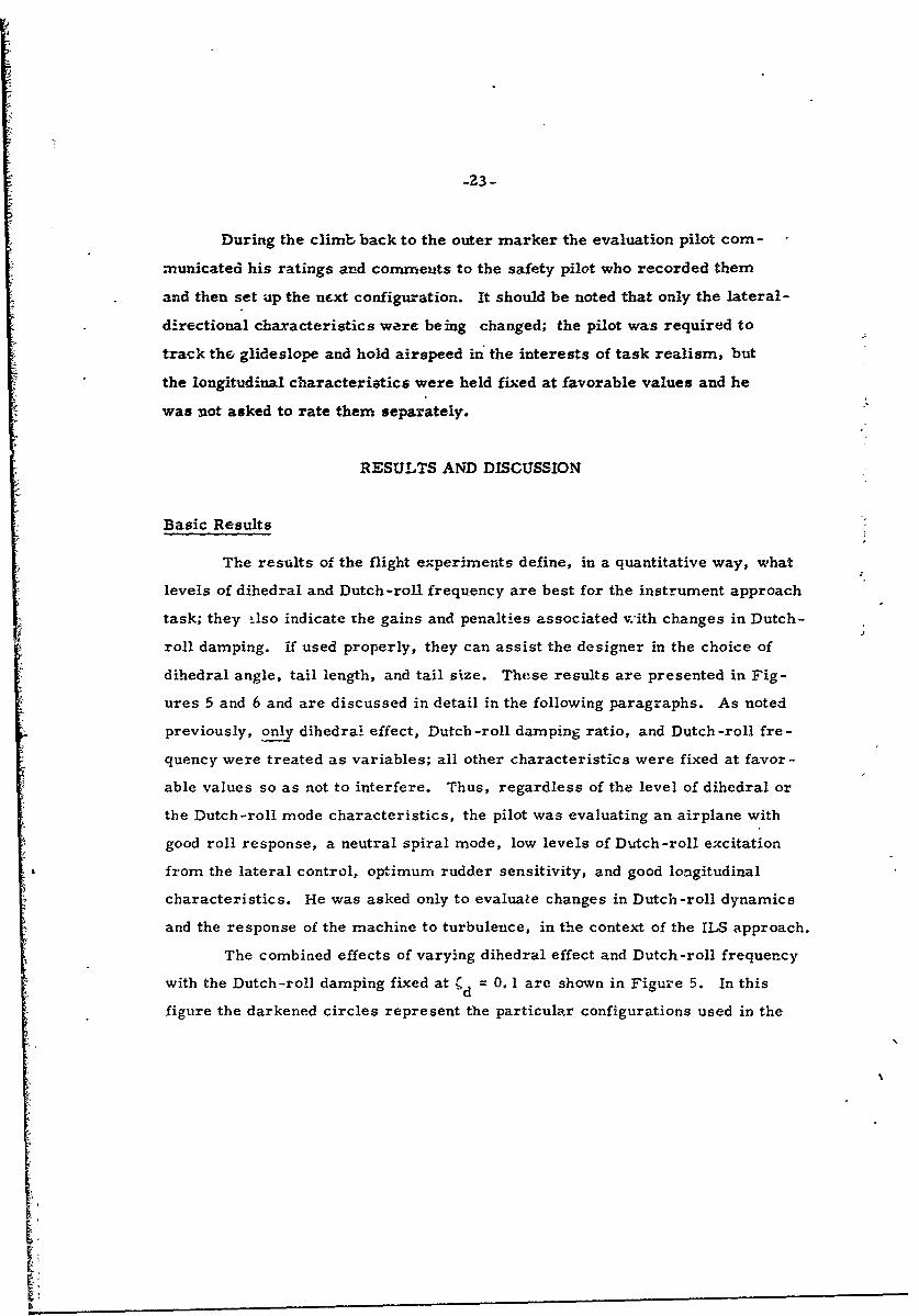
During the climb back to the outer marker the evaluation pilot com-
municated his ratings and comments to the safety pilot who recorded them
and then set up the next configuration. It should be noted that only the lateral-
directional characteristics were being changed; the pilot was required to
track the glideslope and hold airspeed in the interests of task realism, but
the longitudinal characteristics were held fixed at favorable values and he
was not asked to rate them separately.
RESULTS AND DISCUSSION
Basic Results
The results of the flight experiments define, in a quantitative way, what
levels of dihedral and Dutch-roll frequency are best for the instrument approach
task; they ilso indicate the gains and penalties associated vwith changes in Dutch-
roll damping. if used properly, they can assist the designer in the choice of
dihedral angle, tail length, and tail size. These results are presented in Fig-
ures 5 and 6 and are discussed in detail in the following paragraphs. As noted
previously, only dihedral effect, Dutch -roll damping ratio, and Dutch -roll fre -
quency were treated as variables; all other characteristics were fixed at favor -
able values so as not to interfere. Thus, regardless of the level of dihedral or
the Dutch-roll mode characteristics, the pilot was evaluating an airplane with
good roll response, a neutral spiral mode, low levels of Dutch-roll excitation
from the lateral control, optimum rudder sensitivity, and good longitudinal
characteristics. He was asked only to evaluate changes in Dutch-roll dynamics
and the response of the machine to turbulence, in the context of the ILS approach.
The combined effects of varying dihedral effect and Dutch-roll frequency
with the Dutch-roll damping fixed at d = 0. 1 are shown in Figure 5. In this
figure the darkened circles represent the particular configurations used in the

-24-
flight experiments, with the average pilot rating shown adjacent to each test
point. Each configuration was flown an average of six times; three of the four
evaluation pilots did the bulk of the flying, and flew each airplane at least
twice. The pilot rating contours were obtained by fairing curves through the
averaged pilot opinion data, first plotting pilot rating vs. dihedral effect at
constant frequency, and then pilot rating vs. Dutch-roll frequency at constant
dihedral effect. These then served as a basis for picking points on the Wd vs.
L. plot through which the numerical rating contours could be expected to pass.
The dashed segments represent the trends of "he present data; these should be
considered provisional pending further test;ng.
Figure 5 indicates that the best airplane will have moderate normal
dihedral effect and an intermediate level of static directional stability. Quanti-
tatively, this means the dihedral effect stability derivative is best at a value of
about L = -12 rad/ sec2 / rad and the directional stability should be large enough
to give a Dutch-roll frequency of about two radians per second (a period of
slightly more than three seconds). These are not unusual numbers, being
slightly smaller than those for the basic Navion at 105 knots. In the neighbor-
hood of this optimun the ratings change gradually, and acceptable, satisfactory
machines are indicated !or frequencies from about 1. 5 rad/ sec to 2. 8 rad/ sec
provided the dihedral is between L1 3 = 0 and L = -24.
At frequencies below wd = 1.5 rad/ sec the pilot must begin to compen-
sate for lower-than-desirable directional stability; excessive rolling due to
side gusts starts to require compensation at about the L = -24 level. Fre-
quencies greater than about wd = 2. 8 rad/ sec mark the beginning of tendencies
toward excess directional stability which results in undesirable yawing motions
due to side gusts. It may be noted that the "optimum" airplane is one which
strikes a compromise by having enough stability for good dynamic response
and controllability, but not so much that it is disturbed excessively in turbu-
lenc e.

-25-
The results indicate that, provided the frequency of the yawing-type
Dutch-roll motion is favorable, low or even zero dihedral effect in itaelf does
not make an airplane unacceptable for instrument approach flying. Aohough
no configurations with abnormal or reverse dihedral effect are shown on Fig-
ure 5, some preliminary testing was done which indicated that there is no
sharp change in rating as the sign of L changes, and that the constant-rating
contours can be expected to close smoothly on the left-hand side of the axis.
Even if this is confirmed for the ILS approach by further testing, however, it
must be pointed out tiat significant levels of reverse dihedral may prove un-
desirable for other reasons - for example: flight near the stall, if ruddeT
must be used for lateral control; unnatural control in cross -wind landings;
and excessive spiral divergence in situations where heading or bank angle
is not closely monitored.
The low-frequency, low-dihedral case is of special importance because
most straight-wing airplanes tend to have this combination of characteristics
at low speeds [airplanes with swept-back wings tend toward low frequency,
high-dihedral under the same conditions) and in landing configuration. Fig-
ure 5 indicates that even with wd 1. 3 rad/ sec the pilots were'beginning to
compensate for some undesirable characteristics, and pilot commentary in-
dicated that the problems involved difficulty in trimming the airplane in roll
and yaw, poor heading control, and sideslipping due to lack of directional sta-
bility. Preliminary tests with an even lower frequency configuration (wd
0. 8 rad/ sec) indicatcd that the ratings degrade very rapidly at frequencies
lower than one radian per second. AJI in all, the results of Figure 5 suggest
that for the ILS approach there is virtually no penalty associated with low (but
still normal sense) dihedral effect. The designer might well choose a dihedral
angle giving a value of L for the approach which is lower than the optimum
and thus avoid having too much sensitivity to turbulence in cruise.

-26-
The configurations of Figure 5 all had tue same Dutch-roll damping
ratio, d = 0. 1. The effect of changing the damping ratio both to higher and
lower values is shown in Figure 6. It is seen that a sharp degradation of
pilot ra~ig occurs if the damping ratio is reduced to 0. 05, while an in-
Screase to Cd = 0.4, which might be accomplished with artificial yaw damping,
results in only very modest improvement. The fairing of the data indicates
*S that the basic requirement is for a damping ratio of about one-tenth, a level
which can usually Le attained aerodynamically. This value is in agreement
with the findings of Reference 4.
It must be emphasized again that the above results were obtained with
all parameters other than the specific test variables held at favorable levels.
The presence of significant Dutch-roll excitation from the lateral control will
be especially detrimental; even if the rating contours are not changed in general
shape, the numerical levels almost certainly will be. A shrinking effect on the
individual boundaries might be expected. To maintain the rating level associ-
ated with a particular configuration in Figure 5 in the presence of Dutch-roll
excitatiozn, a higher damping ratio than that indicated in Figure 6 will probably
be required - at least for high w TI wd These matters will be investigated in
detail in the next phase of the program.
Interpretation of the Results from a Flying Qualities Research Viewpoint
The previous section dealt with the general features of the results and
their significance to designers; this section will present in more detail the rea-
sons for certain configurations being rated as they were.
(A) The Role of Turbulence. All of the configurations tested were rea-
sonably pleasant and well-behaved (Cooper-Harper rating of 2) when flown in
smooth air. In simulated continuous turbulence, on the other hand, the differ-
ences between configurations began to stand out, and in some cases the turbu-
lence response was the outstanding feature of the airplane. The configurations
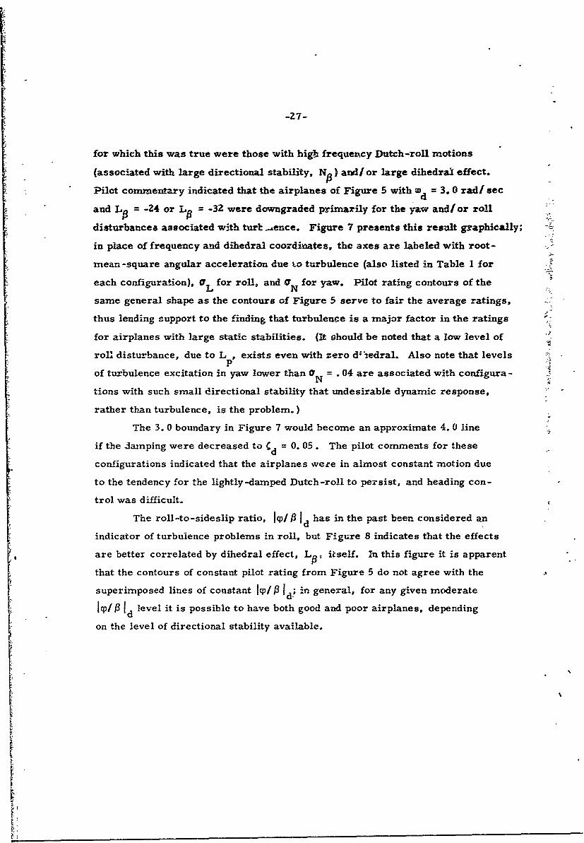
-27-
for which this was true were those with higb frequency Dutch-roll motions
(associated with large directional stability, N 0) and/ or large dihedral effect.
Pilot commentary indicated that the airplanes of Figure 5 with w. = 3.0 radi sec
and L 0 = -24 or L = -32 were downgraded primarily for the yaw and/ or roll
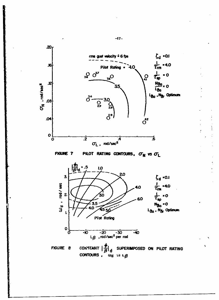
disturbancea associated with turt: _,ence. Figure 7 presents this result graphically;
in place of frequency and dihedral coordinates, the axes are labeled with root-
mean -square angular acceleration due to turbulence (also listed in Table 1 for
each configuration), 0L for roll, and 0N for yaw. Pilot rating contours of the
same general shape as the contours of Figure 5 serve to fair the average ratings,
thus lending support to the finding tl-at turbulence is a major factor in the ratings
for airplanes with large static stabilities. (It should be noted that a low level of
roll disturbance, due to L , exists even with zero d-:edral. Also note that levelsp
of turbulence excitation in yaw lower than a = .04 are associated with configura-N
tions with such small directional stability that undesirable dynamic response,
rather than turbulence, is the problem.)
The 3. 0 boundary in Figure 7 would become an approximate 4. 0 line
if the .arnping were decreased to Cd = 0. 05. The pilot comments for these
configurations indicated that the airplanes were in almost constant motion due
to the tendency for the lightly-damped Dutch-roll to persist, and heading con-
trol was difficult.
The roll-to-sideslip ratio, Ip/• Ad has in the past been considered an
indicator of turbulence problems in roll, but Figure 8 indicates that the effects
are better correlated by dihedral effect, L , iiself. In this figure it is apparent
that the contours of constant pilot rating from Figure 5 do not agree with the
superimposed lines of constant Ica/1 d-; in general, for any given moderate6/0• Id level it is possible to have both good and poor airplanes, depending
on the level of directional stability available.

The .bso-izte values of Vitllo ranin- - _; or are adm. Merg- depidernt
upo- the 2evel ogf tbrh lence used in :•iee simrlatioc, ig rhis ease r=s inmear
veoy y co-pDcc.-ts of 2batb 6 ft seec- As oted im the a=set experia•eai
proced.cre. traversing tis field of tr bu l--eu atiO r s prcd.•ces eiar.
rssideslio 63) of abaruz 2 degrees, roll rate (pi of abcm2 3 deg! see, and 7aw
-The (r) Of aboz 3o-112 degI see, . the dista•irace level 16r con-
figarations =ith small1 stabilityj is very low; for Ihose %hht large 3tability deriva-
tives 4- is high; for- the airplane in the middle of F-igare S. the "opx irnum" airr-
plame. it simply prese~ts a comtinvous pileting task zari carses a degradation
of perhaps cu-hl!o one rating uait z-2mpare-O to an approach iz smocch air.
The pi~ok rratiings would improwe. of course, if the turb,.decce intensity were
lower, but the levf-l used is felt to bee representative of ".nmoderate" disturbances
encc..tered ooerationa-ly.
Finally, it shoul-i be noted that these fi-dinngs u-ith respect to turbulence
are neither new nor mnique; they correspond quite closely, in fact, with those
c.f References Z ae.d 3, and serve to fur-xther emphasize the important role of
turbulence in flying qualities.
(BI The Effects of Dynamics. The characcer of the Dutch-roll changed
considerably over the range of configurations tested: the period went from
slightly more than two seconds to nearly five seconds; the mcde changed from
a wire yawing-and-sideslipping motion at zero dihedral to an oscillation with a
very large roll comn..nent at the highest dihedral tested; and the damping ratio
varied from very light to relatively heavy. In the last section it was pointed
out that the ratings in the high-frequency, high -dihedral areas of Figure 5
were downgraded because of their poor behavior in turbulence. To amplify
this point, the period was neither too short nor the rolling too violent to pre-
vent the pilots from controlling the motions; their comments indicated that it
was mainly the relatively large size and continuous nature of the disturbances

F
*that eaxmfd tLhe= to dwg-rade those codiTgtzrzto=S. T'he dyca~nics of the
DP-cb-zoHl, in -er wozds, were r eing criticized. b- rather the hig
lev-els of static stability wtuic~ accatnpanied those pa.-tical-ar dvna~ica.
On the c.ter band, the prlc ratings for t:e o.-I fre-qenc- (z = 1. 3
[ ad/ sec) ccrfigmrationa are prua-rily due to poor dyns-iicz and th~e associa-
ted co-arolability proble-ns. It shozld be recalled thaz these airplanes had
good roll response chaazcteristics, ard indeed poor roil control itself was
never isted as a factor in the ratings. According to the pilot- comments,
the proble•es are generally moor control ever heading and iarge sideslip
excu•sions. In these cases the txtrbulec-ce disturbances in yaw are small
due to the iow level of directional stability, NB , but roll disturbances are
:)resenw axi become large at high levels of dihedral. Three important
sources of excitation of the characteristically slow j4. 8 second period)
Dutch-roll are thus present: the roll turbulence, which leads to banking
and hence to sideslipping and the complete Dutch-roll; rolling and Yawing
originating in the airplane being out of trim (these low frequency configura-
tions are generaliy difficult to trim accurately because of the "weak" direc-
tional stability that allows the airplane to sideslip easily; on instruments, inF turbulence, re -trimming is a virtual impossibility); and the pilot himself,
who will be trying to suppress the roll turbulence excJzsions and control
the flight path simultaneously.
It is conceivable that the pilot can fly these configurations with pre-
cision only under VFR conditions, wherein the "visual display" seer. through
the window is perfectly integrated and all of the physical cues to the pilot are
in perfect harmony. Under the hood, in IFR conditions, there are difficulties
associated with priorities in the instrument scan, sampling rates, integrationrof the information, and adequacy of the information itself. For example, it is
by no means certain that the yaw rate information available from the instru-
ments - from rate of movement of the directional gyro or from the turn-and-
bank indicator - can be either sensed adequately or monitored closely enough

-30-
by tea pilot to permit- his me= kic effecti'rely o-- yaw'-rate withý thte rudder.. Or.
bank angle inforznatiom a ~znnee fromm a gy'ro 1wrizzon w-ay met give the rather
precis Zo=Ztro oVer bank 2=glt Meeded to I-in dOW a cerjain headiMg, or tE
a'id unitenitional sideslos. it is per•in-r• to .etion here that a series of
runs were mazde in which the pilmo was asked to remove t- blind-flight hood
late in the approach and then rate the conf-iguration sepa-ately for the instr,-
=ent 2n#! ? isua. portions. In no case was the airplarne rated worse for the
visual task, and generally one-half to one unit better.
The matter off piloting technique is important here. Sometimes pilots
indicated that they were controlling heading with the rudder; at ether times,
or for other co.ffigurations, they claimed to be "coordinated, " that is, they
weye moming stick and pedals together while banking and unbanking the air-
plane to achieve heading changes. But for the latter cas'-: the roll control
was the primary one. Analysis of several of the apprcaches nrdicates that
typically the pilots moved the stick and rudder in the same direction (to give
right roll and right yaw, for example) aoout 80-% of the time, in opposite
directiops abott 5% of the time, and didn't move the rudder at all 151% of the
time. This is not conclusive, of course, but such results so far, for the ILS
approach, differ little from pilot to pilot, or between configurations. As a
matter of interest, a sample approach record is shown in Figure 9.
This pattern of commentary and ratings concerning airplanes with
different combinations of L and N should fit a rationale of pilot-vehicle
closed-loop system analysis, but this is complicated by the presence of two
controls, aileron and rudder, and the multiple -loop nature of the ILS task
itself. Before the structure of this system can be defined, specialized data
are needed, such as that from experiments in which the pilot is asked to
track only heading. The response of the airplane to rudder inputs takes on
new importance here, since civilian pilots (as contrasted with the military
jet pilots of References 2 and 3) are inclined by training and experience to

-31-
use it heavily; mos'o previous laterall-directional flying qualities work has
been concerned with roll response to lateral control and thus is of litle
assistance.
Measures of Pilot Activity and Task Performance
Records of the approaches such as Figure 9 - mentioned previously
in ccnt-ection with piloting technique - were examined in an effort to find
correlatio;s between control activity (control position zero-crossings, con-
trol reversals), task performance (localizer and glide slope deviations), con-
figuration parameters, and pilot rating. No significant correlations were
evident in the control activity data. The tracking data showed ar much pilot-
to-pilot variation (and even day-to-day variation with the same pilot) as it
showed bettween configurations, evidence of the fact that a proficient pilot
can maintain a high level of performance in a complex task even while fly-
ing a poor-handling airplane.

-32-
CONCLUSIONS
The following conclusions, based upon experiments carried out with a
variable stability flying simulator, apply to small general aviation airplanes
with good roll mode characteristics, low Dutch-roll excitation from the lateral
control, and near-neutral spiral mode, flown on an ILS approach:
1. The best level of Dutch roll frequency ic ad between 1. 8 and 2. 3
rad/ sec (Dutch-roll period between 2. 7 and 3.5 seconds). This represents
a compromise wherein the level of directional stability is large enough to give
good dynamics, but not so large as to cause excessive yawing in turbulence.
2. Directional stability large enough to produce a Dutch-roll frequency
in the neighborhood of 3 radl sec (2. 1 second period) leads to excessive turbu-
lence response in yaw.
3. Dutch-roll frequencies lower than about 1. 4 rad/ sec (4.5 second
period) associated with low directional stability are undesirable because they
require the pilot to compensate for poor heading control, large sideslip ex-
cursions, and difficulty in trimming the airplane in roll and yaw.
4. Flying qualities for the instrument approach task deteriorate rapidly
for Dutch-roll damping ratios less than 0. = 0.,0 but relatively little is gainedd
by increasing Cd beyond this value - at least for low Dutch-roll excitation in the
roll response. For some cases of high Dutch-roll excitation higher damping
would undoubtedly be beneficial.
5. The best range for dihedral effect is L = -8 to L = -16 rad/ secJ/rad,
but there is little penalty in terms of flying qualities for lower values. Even zero
dihedral effect dces not interfere with the task of flying an ILS approach.
6. Large dihedral effect (L = -24 or more negative) is ,'ndesirable be-
cause it produces excessive rolling due to turbulence.

-33-
REFERENCES
1. Seckel, E., Stability and Control of Airplanes and Helicopters, AcademicPress, New York, 1964.
2. Seckel, E., Miller, G. E., and Nixon, W. B., Lateral-Directional FlyingQualitiesi for Power Approach, Princeton University Report No. 727,September 1966.
3. Seckel, E., Franklin, J. A., and Miller, G. E., Lateral-DirectionalFlying Qualities for Power Approach: Influence of Dutch-roll Frequency,Princeton University Report No. 797, September 1967.
4. Harpe'ý, R. P., Jr. and Cooper, G. E., A Revised Pilot Rating Scale forthe Evaluation of Handling Qualities, Cornell Aeronautical LaboratoryReport No. 153, September 1966.
5. Ashkenas, I. L., A Study of Conventional Airplane Handling Qualities Re-quirements, -Part JI. Lateral-Directional Oscillatory Handling Qualities,
AFFDL-TR-65-183 Part II, November 1965.
\

-34--
In) 0 10 t'- '00 1 v %
b CD 0 0 0 0 0ý 0 0'0o-
0 0' (' ' 4 N 'co t- 0' I'* 00 OD 0 0o 1 0 v 1.3 "C cr N m~ v'~ en v L
b N N N N N ri N c- n~ m on v n tn
'.0 10 '0 '0 '0 '0 -.0 'o v 0 '0 0~ '0k 0 Ili 0c 'l I 0 0 OD co 'D v~ 0> O' 00 -. ~ j cn. . N ' N cn v N'
Cr. a' f- 0- 'e r- N Na, zn '0 N N ' LA a, r- UN LA '0 '0 v* Do '0
-4 C) L OD -I N vJ OD -' N06o 4 C
en M
LA N 'n '0 Na' Nn N a, r- LA coo N L '0 0 a, r-4
' n 0 N,
ca 0 0 0 o 0 '0 tn crn 0 co '0
fil'0 N ~cn 1- 0a'1 0' a' 00 00Co C a, 0'% '0 Co
Ic 0 o IoTo K0 t)o. 0 N A '
r- 004 m. 0 N -4 .N
r- Co t.- 400 v 0 0n 00 0o 00 0 ~ ~ 0 e~L
f1 0 .-l 0, 0, a, N, -4 a, a - 0l
c- Co co LA___ cro CoYIT
-4 -4 -4 -
U~c v0 0 vcCn~0 ( o ci 0 ~ C 00 fn
-4 N q ml- 4 N r~ .- N e ~ - v
Co0 Z N, en -i n - co~ o, om -' '

-35-
Z ND N0 c- ~ COS b 0> 0 0o
a, a' a' t'- '0 0 0 0 00 0 0 -4 N -3 -4 en N
Sb N NZ N cfn c N N m e
'0 10 '0 v01 N -'0 c' o 0 '0 NI N MEco - LA ' CO -4j 0 0 -
0' 0 ' LA N 0 N co
'%0 in00 ~ - 0 00 N
a0 0
'0 '0 - Er)
00
co - -4 -4
C0 N, 0 00 0 0 c~ t- 0 0 0 C
'O 0 '0 '0 r 0 '0 '0 r4) E
W'00 0' 00034-
0 0) 0 00 0 0 0a
0)) en Er) -
0 0 0 0 0D 01 0CO 4 N -444 0*ý ;4 ;
LA0
$4 -- 4
SB0 4 4
N N~ N ~ N N N ~ .
o -N
N N N M N In N N

-36-
~2
PA . "A 11!r a I0ii. a
I~II
___ .V Hal__ __ _
zLi
wrii~Ir ________
w.ji__ _ _ _ _ _ _ _ _ __ _ _ _ _ _ _ _ iUI -iC__ _ _ __ _ _

34

-� I
-33-.
I:
- ,Aa.
8'Cu
'.4
A IjJ
�0
I:
Pd-I
44
I
*1

39-
O ._=_ __ __ _
So~pmmp E N.... • p-_.....
, .. •.. . =, .. .- : ..-...-.-..,..-.. • .:
N-......... - .... ... ..... .........
I----------
-.. .. ; . Ni:•I W . ;1 4P m
•.2
•..• +•++.+,+,..,._.__.__.+1i,. - i "" 4..t "" " ~IIj: ml"ipIstr"wil
.9ljj:iz lui 9j ~ I:~::111~ 2 U:zif * *I I _1.;
2 1 1 . 1.: fl :Wt ::tM H i stt.? t u*: . .. -, r. .!i I: HL du 111:
I~~~ U.-.:d:"",. ®ri l"9• HE.- = +.. .. .-t., ... tM
024 6 M8 02 468 "f
TIME, SEC TIME, SEC
FIGURE 3 ANALOG COMPUTER ROLL RATE AND YAW
RATE RESPONSES TO AILERON STEP INPUTS
3p
p-
1051
p -p
o 2 46 8 0 0
____, SEC:- M- __
FIGURE~ ~ ~ ~ 3 ...-....ME --.--ATEANDYA
RATERESONSS 'O AERO STP IPUT

5-93
S --
=Iw--,
p _ 7p
__ - - - .- -~ __ ___________A__
_0_ ER) _
ILIIJZJZ=I _
s -29- -
p z 1
Ii -ý- T!- M
-- 0 2 4 # 6 I
TIME, SE TM, E
FIGURE 3 ANALOG- COAPLITER ROLL RATE AND YAWRATE RESPONSES TO AILERON STEP INPUTiS
II
- -r
- ~2 -
r OEr
p p
0 V- i ______0_________________
r _ _ _ _ _ _ _ _ _ _
ra
0~ __ 1 4 6 8 1pIE S-EC- -ME SEC _ _ __ _
MURE 4 ___________ RI RTEAND A
RATE, RSOSES ToME RSEC S i

-43--
p
®. -- 4 -•
p ~ -
___ -- -- - --__ _ _ _
p - -•
r -.- : •_•;
r -
4 AL CU ORN
0 2 ,4 68 , 0 0 2 4 6 8 N0TIME, SEC TIME, SEC
FIGURE 4 AM4ALOG COMPUTER ROLL RAE AND YAWRATE RESPc.-OMSES TO RWJDER STEP INPUTS

-44-
- -T
V - 7
r ark
rrrt-
0. 2 3 , 1 2 4 6 6 I
M-E SEC Tom SEC ~
FfJRE ~ ~ -" 4 NLGCMUE RL RT N A
RAT REPNE TORDDRSEPIP

-45-
I0
I g~o CLI
z s U
0 0
QI 0w o I _s
0 0
m*~pi Ppo~d00

S
S6.6
. Wd= L3
0 L$7.0
RAT
0 0
I /'00
SWd= F- rod/s9c
0 Lp=OA Lpq=-16
I. I
0 .1 .2 .3 4 .5DMTCH ROLL DAMPIG RATIO, N
FIGIR 6 PILOT RATING AS A FUNCTION OF DUTCH ROLL
-47-
rmaoat vodli6 fps 930J
PiIVstRoing 4.0 Tim
3.50
S14Le.& pm
00
0D 02 42
d 1.
40 x4.0
6.0 Tsp
44.0
0-10K) 2 -30 -40Lg , rad/sec- per rod
FIGURE 8 CONSTANT is SUPRPOSE ON PlLJDT RATING
CONTOURS, wd :aL

-48-
Conftxctim~ 9 (S. Tabie 1) 9 Fab 1968
-0 0 -1c ff _ ___-
left'__ __ -
"" IL,7 -----
-_t " _ -_ _ 1 . •|- r | . -o . -•-- .. .. •-. ::..___ __
o f24 --A -IML__ __
~~--~Tz -7 ---
-•.- L L -.- -. -a .... .
43 ---5 -3=1--_
"'• - ~ ~-4' • - ;-" .--. =--:: •'..- •- -'. - - -. -'..." -'--.- •-•....;.•-•-,.'----
carftr
- T.. - .. .. .. .. .. . .
-jz •--j s _ _ _21-t~~~l . - T. .:;
0ID 2D 30 40 5T"ime, a
FieURE 9 SAMIPLE TEST DATA : LATERAL. CONTROL AND RUDD)ERCONRO DEFLECTIONS, YAW RATE AM• LOULZERDEVIATONS. SIMULATED TURBULEN.-

A-i
APPENDIX
Lateral-Directional Equations and Approxi-nate Response Factors
The following lateral-directional equations of =otion and apprcximate
response factors are inzlbded for reference parposes:
Y13 ¥6r(--L-1 +aAr - 66r
V V V
2
L;&p 1,"r r(is-L s),66 L 1,6a -L Aft
The "primed derivatives" in the roll and yaw equations incorporate
the effects of product of inertia, I . according to the defiiticnszz
I I
L.=-.I I12 xz
II IIxz xz
Fcr conventional, subsonic airplanes the characteristic equatio-ois
factored into roll mode, spiral mnode, an Dutch-roll roots:
(s - })s + -- 'I + z~ + dd+ = 0rm sp

TJLhe fOUi%;ir-g approximm.ate fzctcrs are orfem zz-Sefa
a ~ Vrm -N
7 Sp
V p V
J3
prov'ided that
is sm~all
Z.JL (+ N) <cI« I
IS
LpL3. 1 L
<<I