flyingcloud
TRANSCRIPT

HOW TO BUILD - FLYING CLOUD

by Sam RablNaval Architect
HARDLY were the plans for Buddy off thepress than Modern Mechanix boat fans
everywhere began to demand a large boatalong the same general lines. The simpleconstruction of this craft placed her withinfinancial reach o£ every ambitious youngsterwho could wield a saw and push a plane.Many of the original craft were built withexceptionally fine results; one of them hav-ing crossed the Gulf of Mexico.
Men who earn their living today must beback at the office or shop Monday morningand of course, require a boat that will notrequire hours to dock. Nevertheless, the craftmiust be large enough to provide comfortableaccommodations for the average family andnot cost too much to build. With all of theseessential points in mind plans were drawn upfor this "ideal" boat and eventually the boatitself was constructed and christened "FlyingCloud" after that famous old American vessel.Somehow we feel that the spirit of old DonaldMcKay, designer of the original sailor, will
down kindly upon our miniature version.
Flying Cloud may be built as cheaply aspossible or it may be constructed of expensivematerials. The power plant is either a con-verted auto motor or any inexpensive marineengine. The latter is preferred due to itsefficient cooling system which does away withthe problem of heat in the cabin. Toiletfacilities have been provided and all othernecessities of extended cruising have beenincorporated into her make-up. The buildercan either adopt the cabin plan which wehave designed for Flying Cloud or fit one ofhis own to the existing interior. You mayfit the sailing rig or leave it off depending onyour own whims. As an out and out motorboat she still has pleasing lines and the draftmay be made less than shown by taking threeinches off the depth of the keel. While it willnot be within the scope of this article to gointo the detail of laying down the lines andfitting each and every piece of material in thestructure we will refer the reader to our HowTo Build Twenty Boats for this information,Materials used in Flying Cloud constructionmay be any locally obtained wood suitablefor boat building. Buddys were built fromas many different materials as are foundaround the world from New York to Singa-pore and all are a success. Good solid and wellmade joints contribute more to the successof any boat than the excellence of the ma-terial.
After the backbone is laid down on a largesheet of building paper the shape o£ thevarious parts are transferred to the woodeither with a tracing wheel or by drivingsmall brads through the outline, with-draw the paper, leaving the brads standingin the wood. The thickness of the stem andkeel timbers are such that the ordinary smallworkshop bandsaw will handle them but theeasier method is to take the timbers to a millthat has a large bandsaw and let them do thejob. After the timbers are cut and ready toassemble they should be temporarily held to-gether with clamps and a saw run between
each joint until the surface is wood to wood,This process is repeated each joint of thebackbone and after all joints are thus fittedthey should be smeared with "Staytite" orother similar cement, or a good roofing cementto exclude water and most of all the destruc-tive toredo found along the seacoast Thejoints are made with drift bolts of 1/2-inchgalvanized iron headed up over clinch rings orgalvanized iron washers. Holes for the driftbolts are drilled a sixteenth smaller than thebolt and the bolt slightly pointed to enter thehole. This pointing is done cold so as not toharm the galvanizing any more than possible,though bolts with nuts and washers may beused if the builder so prefers. After thebackbone is assembled the apron of 2"x8"material is securely fastened to the top of thekeel using cement as before to seal the joint.This member is left square until the plankingis fitted. The backbone is now set up in itsproper position on the ground or shop floorbeing sure to have the proper slope on thebottom of the keel and the stem perfectlyplumb athwartship.
The main frames are now gotten out alongwith the transom as shown on the plans, de-ducting the plank thickness, and all jointsassembled with 1/4" galvanized carriage bolts,the joints should be well painted with whitelead. The notches are cut for the keel,
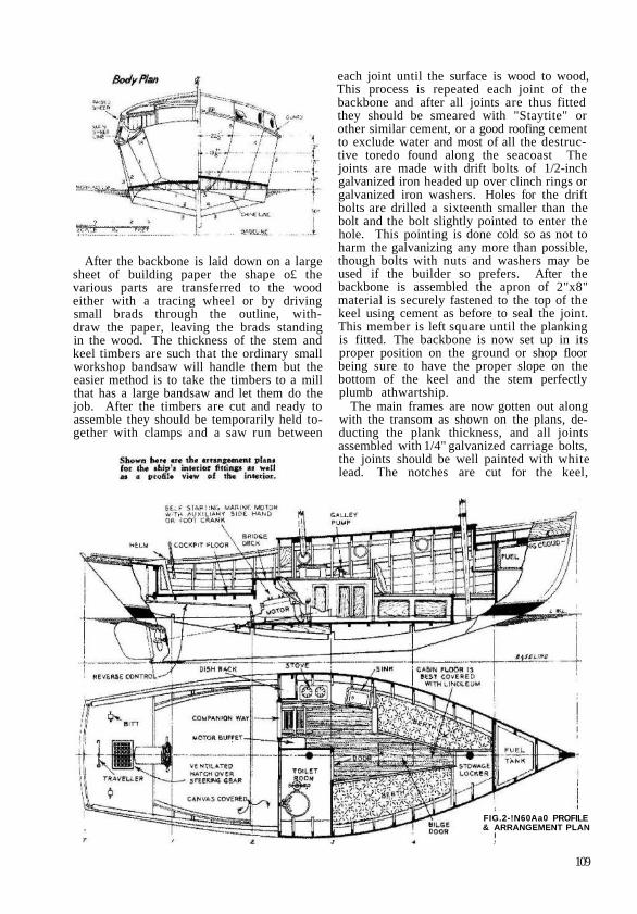
FIG.2-!N60Aa0 PROFILE& ARRANGEMENT PLAN
109

stringers, chines and clamps as shown Thenotches for the stringers being half waybetween the keel an.d chine or in thirds iftwo stringers are fitted. The stern knee is seton the keel apron and the transom attachedto it. This should be perfectly plumbed andeither fastened to the shop rafters to keep itso, or braced to the ground with good heavyshores to keep it from moving. The framesare then fastened to the keel, being sure tokeep them at perfect right angles to the keeland set perfectly vertical. After all framesare set up they are checked for plumb and
squareness and then securely braced to 'theshop rafters or the ground so that they willnot go out of line while the boat is being con-structed. If the structure is erected out in theweather it will be well to give it a coat of goodpaint to protect it. This should be the pro-cedure even if the boat is built under coveras wood will last a lot longer if properly pro-tected. The best paint to use is one of thenew aluminum primers, now on the marketeither purchased ready mixed or mixed byyourself.
With the frames and transom properly

braced, the chines and clamps are bent in, thustying the structure together rigidly. In bend-ing the chines and clamps the best procedureto follow is to bend them in pairs, thus equal-izing the strain on the two sides of the boat.They are best pulled together with a blockand fall fastening them to the stem andworking aft. They should be procured inone piece if possible, and if this is not possi-ble a butt joined should be made with a re-inforcing piece at least three feet long backingup the joint. The intermediate frames arenow fitted starting from the transom andworking forward. Forward of main frame
number four they will begin to take curva-;ture and the shape of these frames is obtainedby bending thin strips of wood between framethree and the stem and picking up the shapefrom these strips or rib-bands, The stem rab-bit is cut by the same method. The upperframes are now fitted by making patterns atthe main frames and fitting the upper framesat these points. The upper clamps are nowbent in. and the intermediate upper frames setto match the lower ones. Tops of the mainframes should be well braced to take thestrain of bending the upper clamps.
A pattern of the deck beams is now made

to the curvature shown on the plans and theupper clamp trimmed off to suit this curva-ture. The top frames are also sawed off tosuit this crown. The beams are now gottenout and dovetailed into the upper clamps. Fitall beams all the way across the boat and cutthem out for the companionway later. Nowis also a good time to fit all cockpit and cabinfloor beams before the planking is in place assecuring good fits is easier at this time as wellas having the beams in to take plankingstrains. Mast pardners as well as base blocksfor bits and cleats will be much easier to fitnow and these should be attended to beforethe planking and decking goes on. The wholeof the structure should now be thoroughlypainted, The chines and apron should bebeveled to suit the bottom planking by layinge straight edge between the chine and keel,and drain holes should be cut in all of thebottom timbers to allow the free passage ofbilge water to the pump. Now is also a goodtime to fit the gas tank and the fresh watertanks as well as motor control rods andelectric wiring that will be difficult to get tolater.
The side planking is now fitted and may berun in parallel strakes or evenly dividedbetween chine and sheer as the owner sodesires. If run in parallel strakes, stealerplanks will have to be run in at the sheer andchine to fill out the additional girth forward.These should not end in sharp points but be
nibbed into the plank directly below them.The edges of the planks should be outgagedso that they are an eighth inch open on theoutside for caulking. No side plank shouldexceed eight inches in width. The planksshould be screwed to the stem and transombut nails may be used to attach them to theframes. Butts of the side planks should bespaced well apart to preserve the strength.The bottom planks are laid athwartship atabout forty-five degrees to the keel andtreated the same as the side planks. A stripof flannel or old woolen cloth should be in-serted between the chine and planking as wellas the apron and the bottom. This flannel orwool should be smeared with Staytite reduceda little with linseed oil to about the con-sistency of thick molasses. The cement shouldbe just thin enough to squeeze out when theplanks are set up if a good tight joint is de-sired. Black Staytite is recommended forwork below the water line and the gray forwork above, Never use the black cementwhere white paint will be used over it. Theplanking on the raised sheer is fitted similarto the side planking, and if a classy job is de-sired should be of mahogany and finishednatural. The decking in the bow well will beeasier to fit if the planking of the upper sheeris delayed until this job is finished.
Now is a good time to get in the motor bedsand install the motor. The exhaust piping aswell as all fuel and water lines will be a lot

easier to fit at this time. With these in placethe cockpit floor should be laid and canvassed.The steering gear installed and then the twoends of the cockpit built up of tongue andgrooved staving with joints painted. Thebridge deck is now laid and canvassed. Thecockpit canvas turns up under the trim aroundthe floor so that it can be easily renewed. Thebridge deck canvas is turned down over theforward cockpit end and up under thecabin end bulkhead to make a weather-tightjob. A generous application of gray Staytitecement will insure watertightness. The cabinend bulkhead is now completed and trimmedoff flush with the top of the beam. Door postsare installed and the cabin top is ready to belaid. This is laid up using tongue and groovedmaterial with a vee edge, or beaded edge asthe builder desires. It will be found that thevee edge is much easier to paint. The plank-ing o£ the raised sheer should be left an inchand a half high forward of the cabin andthe cabin top material worked to a thin edgealong the raised sheer at the bow to allowthe cover board to finish out as a rail cap for-ward.
When the cabin top material is close enoughto the eompanionway to support the beams,they are cut and the headers for the com-panion hatch fitted. The cabin top materialis then continued across to the side of theboat. The top is coveted with number tencanvas with the material laid up with either
a seam down the center, or across the hullif narrower material is used. In event thatthe material is laid across the boat all seamsshould lap aft. All of the canvas throughoutthe boat is either laid in marine glue or whitelead thinned with varnish. Seams and edgesof the canvas are secured with 1/2" copper orgalvanized tacks spaced on no more thanthree-quarter i n c h centers. The canvasshould be wet down immediately after layingand painted with a priming coat when par-tially dry. The forward and aft decks are laidup in narrow strips of edge grain materialand the seams caulked. They can either befinished natural or painted as the builderdesires. The seams of these decks are filledwith deck seam composition or gray Staytite,Sufficient material should be allowed aroundall deck openings when the canvas is laid toturn up inside the framing of these openingsto keep the water out. After the canvas isprimed the cover boards may be laid in thinwhite lead.
The cabin interior as laid out, is one whichhas given much satisfaction over a periodof years in all small motor boats. It is verymuch similar to a very popular standard smallcruiser now on the market which shows tre-mendous sales. You may prefer another ar-rangement and you may suit yourself onthis matter, keeping only in mind that theweights should be similarly disposed. Theeompanionway, of which details are shown,
113

is located on the port side. In the cabinproper the galley is located outboard of thecompanionway steps. Inboard of the stepsthe toilet bulkhead is constructed on center-line,and- a small buffet covers as much ofthe motor as will project toward the steps.This buffet should be removable so as to getat the carburetor side of the motor. Tongueand groove ceiling three-eighths thick shouldbe used on the toilet bulkhead, or it may beconstructed of 1/4" masonite as will be ex-plained later. The galley panels are alsoconstructed of masonite or waterproof ply-wood as shown. The toilet door panels shouldbe pierced with a jigsawed designof some sort to allow air to enterthe toilet at all times.
The toilet is a small marine bowl
of the pump type and should be installed withthe proper seacocks on intake and outlet withstrainer intake to prevent clogging. Leadpipe should be used for all connections. Whileit will be impossible to stand upright in thetoilet, it is still possible to install a washbasin should the builder desire one. Thisshould be of the folding type, and located onthe forward bulkhead in such a position thatit may be used when the bowl is used as aseat. The generator side of the motor is ex-posed in the toilet allowing free examinationof all the many parts located on this sideof the motor. The toilet should be providedwith a port light facing the cockpit for ven-tilation, and this port of course should befitted with a curtain. Should the builder de-sire, a vent can be fitted through the eabintop to aid in venting the toilet, but this willform a stumbling block in going forward ona dark night if not properly located. Theinterior of the toilet should be finished inwhite above the sheer line and a light greenbelow.
On the forward side of the toilet bulkheada shelf should be built to hold books and themany other what-nots that collect aboard aboat The berths are of the conventionaltype and may be either fitted with plaincushions or those of the box spring type aswill be dictated by the builder's pocketbook-Forward of the berths is located another shelfas shown on the plans. Stowage space isprovided on the starboard side beneath theshelf. Should the builder desire, this spacemay be enclosed by bulkheads reaching tothe deck, thus forming a locker in whichshore clothes may be hung without fear oftheir getting mussed. The shelf forward alsoprovides space for a radio which, if fitted,should be provided with an antenna. Onstation five a bulkhead is constructed extend-ing between keel and deck and clear acrossthe boat. A door should be provided in thisbulkhead below the level of the gas tank soas to give access to the bow of the boat andthe chains which will be stowed beneath thetank.

On the interior all trim may be of ma-hogany and varnished as here it will not beexposed to the weather, All panel work maybe very easily made from masonite or ply-wood by simply routing a groove of the re-quired size in the rails and styles of the panelsand setting the plywood in this groove as thepanels are assembled. Panel work will be adistinctive advantage due to its ability ofbeing easily removed for perodically paint-ing the inside of the planking and for inspec-tion and repair if necessary. All panelingshould be installed with screws. The ceilingof the cabin should be In all cases finisheda bright color to improve the lighting. Theunderside of the beams may be champferredor fitted with mahogany caps that can be re-moved when the ceiling is painted.
The flooring of the cabin should have aremovable section so that the bilges may beinspected and painted. Linoleum on the floorwill be a big aid to keeping the cabin clean,and curtains at the ports will give the in-terior a homey appearance. The drainboard
and sink may be of monel metal or galvanizediron but in either case it should be neatlyapplied and all joints made watertight. Asmall galley pump should be fitted at the sinkto draw fresh water from tanks located underthe cockpit floor. A small spirit stove orone using canned heat is located aft of thesink. A dish rack is built on the aft cabinbulkhead to carry the ship's crockery. Be-neath the galley platform there will be roomfor cupboards to stow canned goods, andshould the builder desire, there will still beroom to install a small icebox. All loosecushions should be of the life preserve typeto avoid carrying these very necessary ad-juncts as required by law. I would stronglyrecommend a two and a half gallon fire ex-tinguisher of the foam type be installed ratherthan the ordinary one-quart liquid type,Many a beautiful cruiser has burned to thewater's edge because a quart of liquid wasjust a little shy of being able to quell a fire.
A bell and whistle are also required bylaw as well as sailing lights which will con-sist of a red light to port and a green lightto starboard. A bow light must be fitted be-tween the skeen chocks and a stern light high.

enough to show over all other sail-ing lights on the boat will be fittedaft All of these lights should becombination oil and electric. Whenproceeding under sail alone only thered and green lights should show.When under sail and power a boat isconsidered a power boat and as suchmust carry all lights listed before.The cabin lights should be of thedome type and all lights must bedouble contact as there is no con-venient steel chassis to ground to asin a car. Ail wiring should be in-
stalled in neat moulding so as to bereadily accessible in case of short cir-cuit. The cabin dome lights may beof the regulation auto type which arejust as good as most marine lights andcost about half as much. Outlets forthe sailing lights should be madethrough watertight fittings sold forthis purpose. While on the subjectof lights, an old auto headlight maybe installed on the spreaders aft toform an efficient flood light to lightup the deck when going aboard atnight or when an emergency arises to giveproper light to work the boat. This light willalso be found handy for night fishing where alanding net might be required. All wiresshould be of the lead covered waterproof type.
On the after deck there should be fitted twosmall bitts securely fastened for towing adinghy or a disabled boat if necessary. Asmall ventilated hatch should also be fittedon the deck over the tiller or quadrant with
hatch cover to fit over wood ventilator.A standard type boom jack should be made
to take the main boom when the mainsail isfurled. A ring buoy attached to this so as tobe readily removale has often been an instru-men to which many people owe their lives.This buoy may be dolled up with the boat'sname and the owner's and club flags to lookreal yachty. A binnacle may be fitted in thecockpit ahead of the wheel box if desired or

the ordinary box compass may be used in anyposition convenient to the helmsman. If thecompass be of the box type it should be in-stalled so as to set in a series of strips on thedeck so that it will always he placed in thesame position. In this way only is it possibleto log the courses and follow them at all times.While it was felt that topping lifts on suchsmall booms would be a nuisance, they maybe fitted if the builder so desires. The top-ping lift should be bearded in the way of thegaff to prevent chafing and to give the boata real go-to-sea look.
Well constructed and well found FlyingCloud will be able to do coastwise cruisingalmost anywhere. To consider an oceancrossing in this boat would be folly eventhough boats smaller than she have done thesekind of voyages. This boat was designed as acomfortable cruiser and should be consideredas such. Her cockpit is much too large to taketo sea and her bottom is not strong enoughto withstand the sort of punishment whichsuch a voyage entails. There is no way toadapt this boat to such work but at some laterdate we will publish an enlarged edition ofBuddy which will be specifically designed tofollow the track of the Hawkshaw, a Buddythat poked her nose into such far places asCuba and saw the coast of Yucatan over hertaffrail. This boat will be the answer to themany letters of readers who had the yen togo off shore just as Flying Cloud is the answerto those desiring comfort to the more adven-turous type of cruising.
With the major parts of the hull com-plete, the fittings may be installed. The.chain plates to take the shrouds must be in-stalled before the sheer moulding is in place.The freezing port in the bow well should becut in and covered with a door of the samematerial as the raised sheer planking andarranged to swing out so that it will spillwater should a wave come over the bow. Thecompanion slide and cover can next be fittedas shown on the plans. A strip of coppershould be used to cover the joint on the for-ward end, or many of popular weather-stripsections on the market may be used at thispoint. Before the interior woodwork is fittedthe drains from the cabin top should be con-structed of one-inch lead pipe set as close tothe cover board corners at the after end ofthe cabin as space will permit. The cockpitdrains should be made from the samematerial with a leather flap tacked over theiroverboard ends to prevent a wave from work-ing back into the cockpit.
The rudder is constructed of steel or brassplate with the stock of the same material. Ifthe rudder is of brass, its thickness should be1/4" and the stock of 1-3/4" dia. material.The rudder stock is slotted and brazed to theplate as is also the short stub at the bottom ofthe rudder which forms a pivot through ahole bored in the returned end of the ruddershoe which should be of 1/2" brass, threeinches wide. If the rudder is to be of steelplate, the stock will be of cold rolled steelbar electrically welded to the blade. The

shoe will then be of steel also and the whoJeassembly galvanized after welding. Therudder stock is carried through the hull, in-side of a piece of brass pipe or galvanized pipe
to correspondw i t h ruddermetal, screwedinto a propersize h o l e int h e s t e r nknee. At thetop of t h es t o c k theres h o u l d befitted a tilleror quadrant,which in turnis connectedto the drumof the steeringw h e e l with
flexible steel cable. Should the builder sodesire a hand tiller may be fitted, in whichcase the stock is carried up through the afterdeck. As there will be a reversing gear fittedto the motor, some means will have to be ar-ranged to positively stop the rudder fromturning any further than thirty-five degreeseach side of the centerline.
The spars may now be constructed fromOregon pine or spruce. They are first workedsquare with all the proper tapers incorporated.After the spars are squared and all humpsworked off of their surface they are againworked to an octagon shape. The corners ofthe octagon are again worked off, and finallythe spars are rounded. A hollow sparplanewill be a lot of assistance in this operationif one can be procured. At least five coatsof hot linseed oil should be painted on eachspar and after being sandpapered they shouldbe given three coats of good spar varnish. Ifbright work is eliminated in the constructionthe spars may be painted. This of courseexcepts the foremast as far as the gaff willtravel. This section should be oiled and given
T
118

a coat of mastine grease. The bands andwithes should be purchased before the sparsare made and the spar worked to a diametera little larger than the band at the point wherethe band is to be located. On the masts it isgood practice to allow a shoulder at least aneighth inch larger than the band so that theband will not slip down the mast when theturnbuckles are set up. At points where theblocks or stays are looped around the mast,shoulder cleats of hardwood should be fitted.These cleats should be slightly mortised inthe mast so that they will not put all of theload on the screws attaching them to themasts. The foremast should have a thin brassplate attached at the point where the gaff willswing so as to eliminate wear on the spar atthis point. This plate should be carried atleast three-quarters around the mast andfastened with escutcheon pins. The center-line of the plate will face aft.
The wire rope rigging should now be madewith all ends aloft spliced or looped as re-quired. Splicing is highly recommended asit will give the rigging a professional look. Inevent of the builder being unable to splicewire rope it may be turned back on itself andserved and soldered as shown. All loopswherever fitted should be served with Italianyacht marline to prevent wear on the metaland improve its appearance. After the sparsare stepped the lower ends of the shrouds andstays are spliced to the correct length, to fitthe turnbuckles when they are three-quarters.

open. This allows them to be set up properly.No wire should be tightened beyond the pointat which it is reasonably taut so as not to setup undue strains in the hull and spars. Besure that all manila ropes are rove and allblocks shackled or set in their proper placesbefore the spars are sent aloft. Ail ends ofmanila line on the boat should be securelyserved with sail twine waxed with beeswaxso that they will not fray out Here thebuilder will be able to show his marline-spikeseamanship by producing work that the oldsailors loved to term "ship-shape and Bristolfashion."
The sails should be of six-ounce canvasand provided with sail covers as the foresailwill not be convenient to remove after every
,;run. Khaki sails look well on this type ofyacht, especially so if the hull is finished in adark shade. The sails should be thoroughly
reinforced in all corners and the mainsailshould be fitted with sail battens. As the sailsare in this case auxiliary to the motor theyneed not be constructed with the precisionthat is required of racing sails. Strengthrather than shape should be the rule. Thesails are laced to both main andfore boom with lacing eyes asshown. All halyards and sheetsshould be led to the end of theraised deck and belayed oncleats as shown on the deck plan.The locations of these leadsshould be memorized so thateven on the darkest night, insailors' lingo, you will "knowthe ropes." While ordering therunning rigging it may be wellto include two mooring lines of
120
3/4" manila, 20 feet long, which shouldbe neatly eye-spliced on one end. The freeend should be seized or served.
With the exterior finished we can turn ourattention to its painting and finish- Thereisn't a prettier job afloat than those whosewoodwork is of mahogany finished natural.In connection with this also there are nonewhich occasions more work to keep themlooking this way. For the man who has plentyof time and likes to fuss around cleaningvarnish and scraping down whenever it isneeded, the bright work will have a lot ofappeal, but to the man who really wants plea-sure afloat I would strongly recommend fish-erman finish with all woodwork painted. Myown preferences would be a green bottom,black hull and buff decks, with all trimpainted white. In any event secure goodmarine paints which are the cheapest in thelong run. Every coat applied to the hull shouldbe sanded and nil seams of the plankingputtied flush with a good seam compound.
Completed, "Flying Cloud" will furnish itsbuilder with endless hours of enjoyment suchas only the deep blue water can offer. Care-ful construction will result in a truly beauti-ful craft that can be looked upon with pride.