flywheel, turbocharger, hydraulic cylinder
TRANSCRIPT
Presentation on Flywheel, Turbocharger, Hydraulic Cylinder
Supervised by:-Engr. A.H.M Fazle ElahiLecturer,Khulna University of Engineering & Technology.
Submitted by:-Md. Habib Ullah Khan
Department of Mechanical EngineeringKhulna University of Engineering & Technology, Bangladesh

Outline:
1. Flywheel
2. Turbocharger
3. Hydraulic Cylinder
1.0 Flywheel:
A flywheel is a rotating mechanical device that is used to store energy & the amount of energy stored in a flywheel is proportional to the square of its rotational speed.
Amount of Energy α rotational Speed
Principle of Flywheel:
1. When torque is applied to the flywheel its energy is conserved in its rotational momentum.
2. When the energy is needed, the energy is harvested by engaging the clutch plate and the flywheel slows down.
3. The energy harvested is transferred through the gear box, propeller shaft, differential, axle to the wheel.
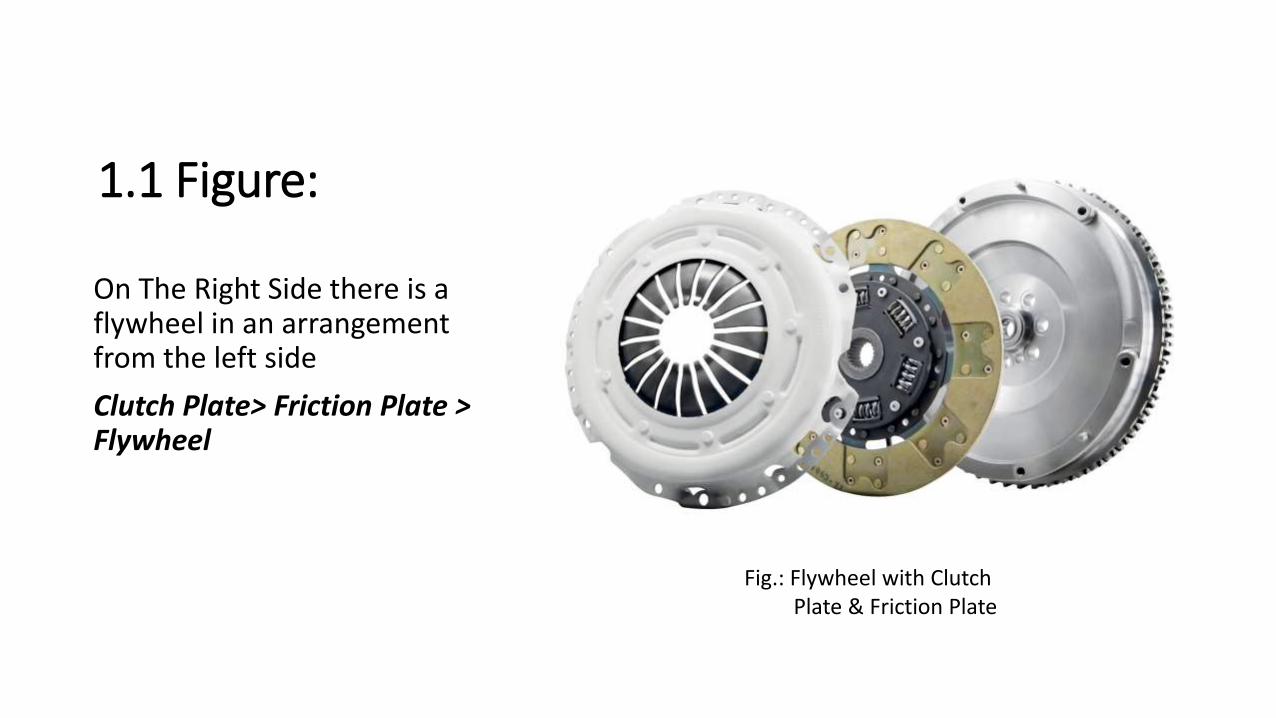
1.1 Figure:
On The Right Side there is a flywheel in an arrangement from the left side
Clutch Plate> Friction Plate > Flywheel
Fig.: Flywheel with ClutchPlate & Friction Plate
1.2 Flywheel Importance:
I. In case of Reciprocating engine the energy source is discontinuous
II. For discontinuity there would be problem when transferring power to the wheel
III. Flywheel is used to transfer power to wheel continously

2.0 Turbocharger:A turbocharger is a device that is used to increase engine efficiency by forcing extra air into it. It is a turbine driven forced induction device.
Principle of a Turbocharger:
1. Turbine is run by passing the hot exhaust gases
2. As a result compressor wheel rotates & sucks air at a high pressure from the atmosphere & forces them inside the combustion chamber
3. Due to extra air engine gets enough oxygen to perform combustion properly
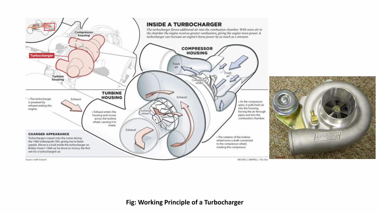
Fig: Working Principle of a Turbocharger
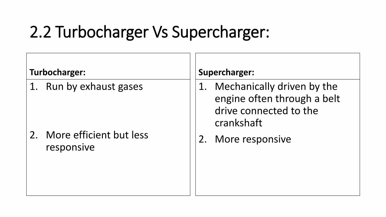
2.2 Turbocharger Vs Supercharger:
Turbocharger:
1. Run by exhaust gases
2. More efficient but less responsive
Supercharger:
1. Mechanically driven by the engine often through a belt drive connected to the crankshaft
2. More responsive

2.3 Turbocharger Importance:
Turbocharger is an important accessory for engine to increase the engine efficiency
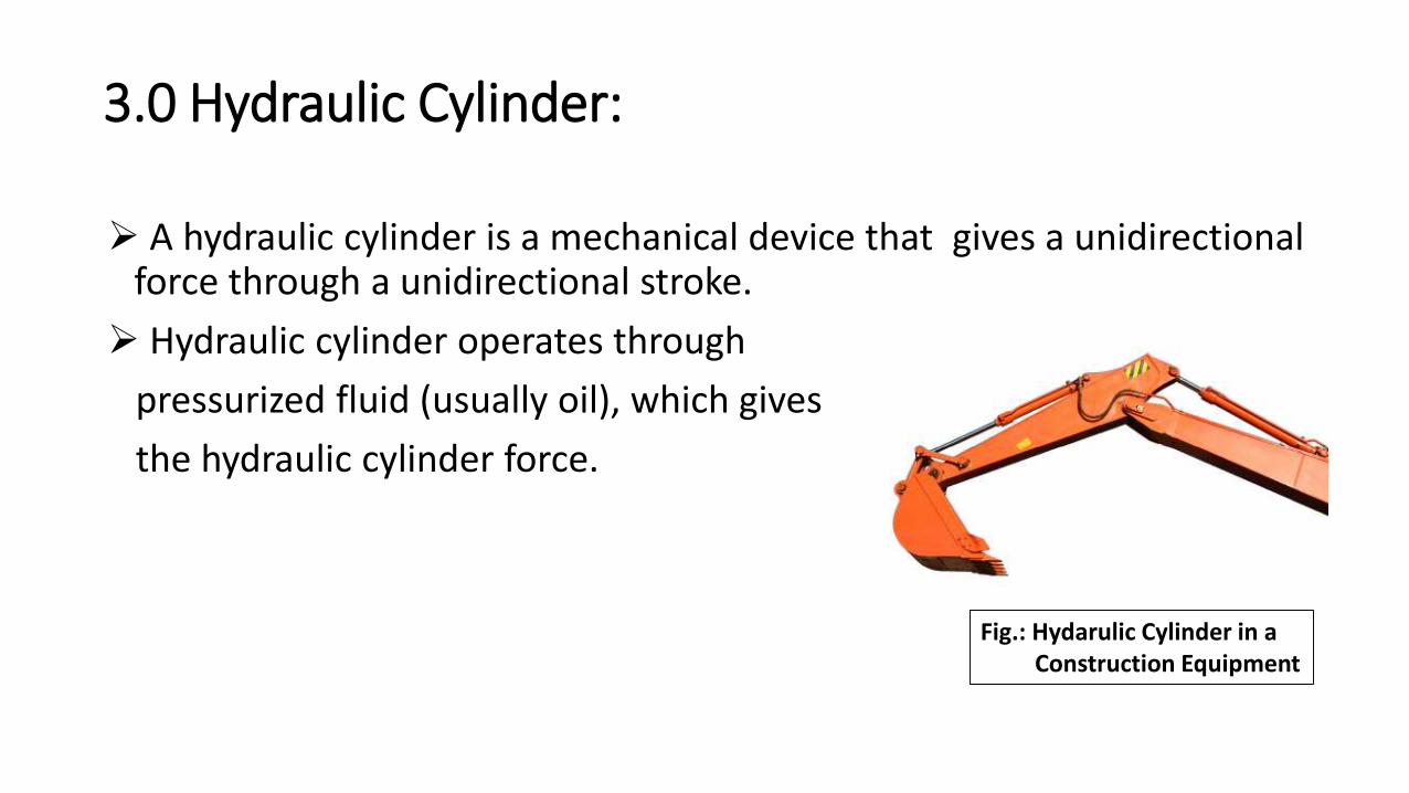
3.0 Hydraulic Cylinder:
A hydraulic cylinder is a mechanical device that gives a unidirectional force through a unidirectional stroke.
Hydraulic cylinder operates through
pressurized fluid (usually oil), which gives
the hydraulic cylinder force.
Fig.: Hydarulic Cylinder in aConstruction Equipment
2.0 Main Parts of a hydraulic Cylinder:
1. Hudraulic Pump
2. Hydraulic Ram
3. Control Valve
4. Oil Tank
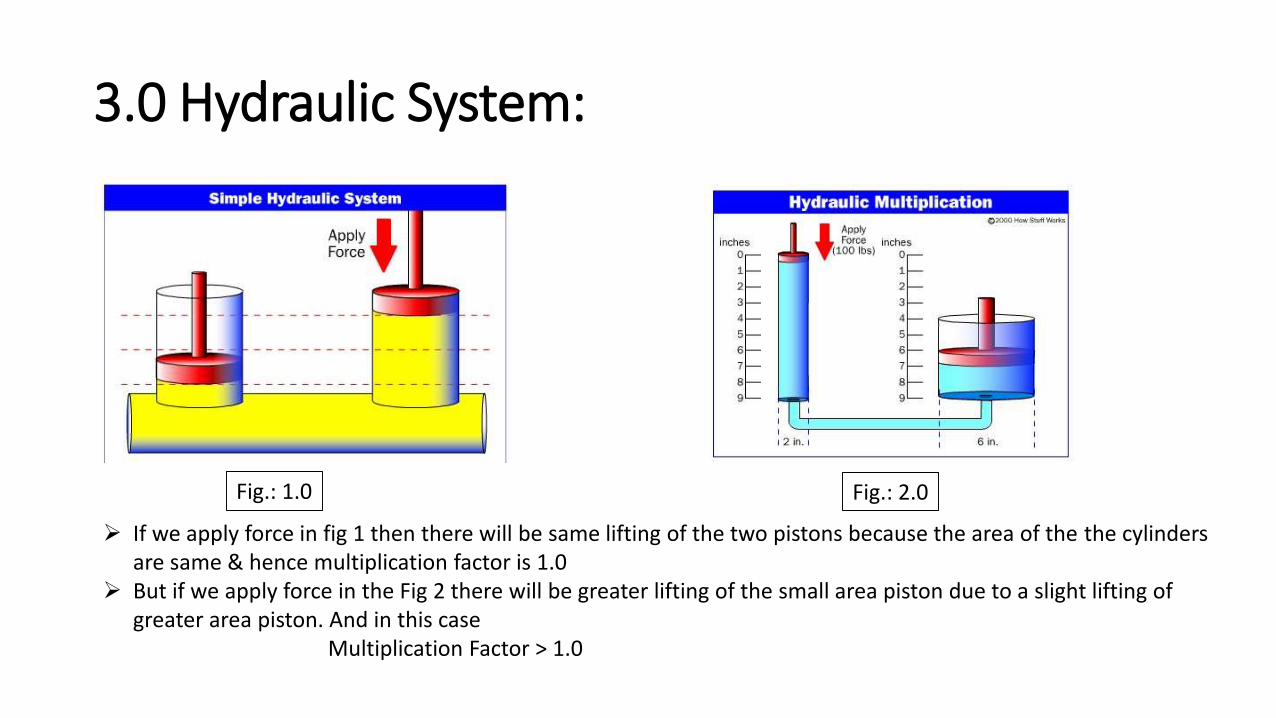
3.0 Hydraulic System:
Fig.: 1.0 Fig.: 2.0
If we apply force in fig 1 then there will be same lifting of the two pistons because the area of the the cylinders are same & hence multiplication factor is 1.0
But if we apply force in the Fig 2 there will be greater lifting of the small area piston due to a slight lifting of greater area piston. And in this case
Multiplication Factor > 1.0
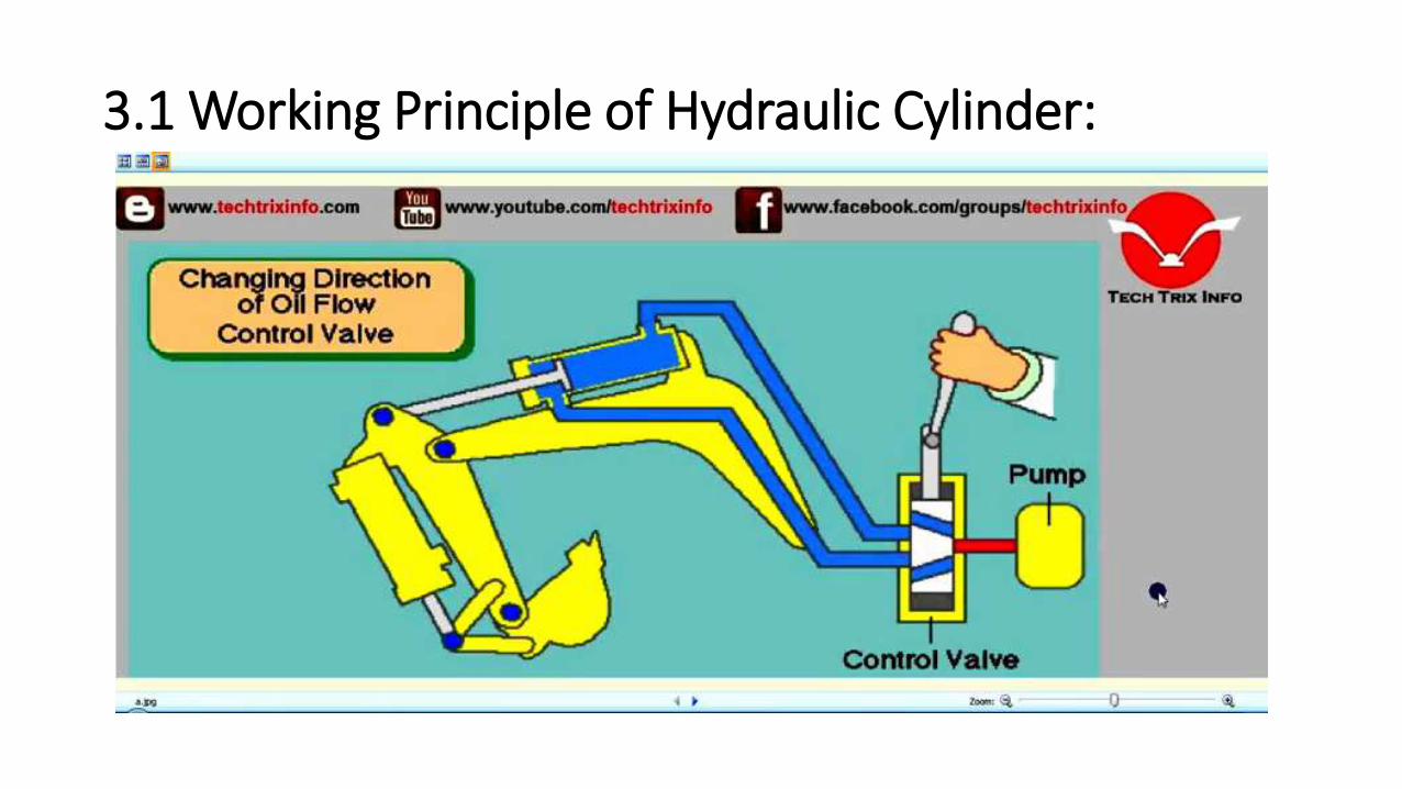
3.1 Working Principle of Hydraulic Cylinder:

Fig.: Tipper Truck With Hydraulic Cylinder
4.0 Applications:
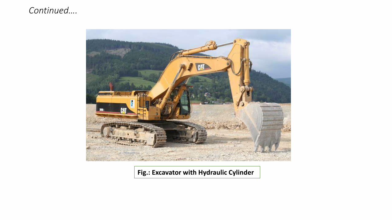
Fig.: Excavator with Hydraulic Cylinder
Continued….
Continued….
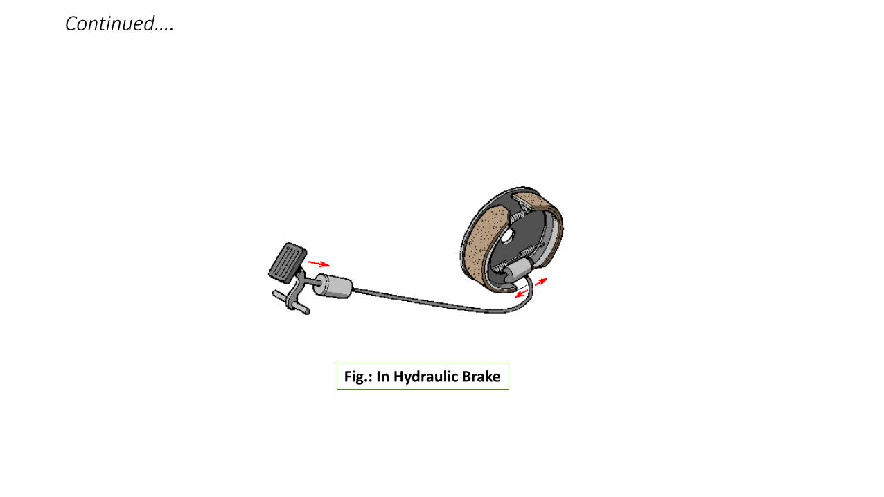
Fig.: In Hydraulic Brake

Thank You ALL