flywheels - sandia.gov · flywheel systems are being developed to store electrical energy. these...
TRANSCRIPT

SANDIA REPORTSAND2015-3976Unlimited ReleasePrinted May 2015
Flywheels
Donald Bender
Prepared bySandia National LaboratoriesAlbuquerque, New Mexico 87185 and Livermore, California 94550
Sandia National Laboratories is a multi-program laboratory managed and operated by Sandia Corporation, a wholly owned subsidiary of Lockheed Martin Corporation, for the U.S. Department of Energy's National Nuclear Security Administration under contract DE-AC04-94AL85000.
Approved for public release; further dissemination unlimited.

2
Issued by Sandia National Laboratories, operated for the United States Department of Energy by Sandia Corporation.
NOTICE: This report was prepared as an account of work sponsored by an agency of the United States Government. Neither the United States Government, nor any agency thereof, nor any of their employees, nor any of their contractors, subcontractors, or their employees, make any warranty, express or implied, or assume any legal liability or responsibility for the accuracy, completeness, or usefulness of any information, apparatus, product, or process disclosed, or represent that its use would not infringe privately owned rights. Reference herein to any specific commercial product, process, or service by trade name, trademark, manufacturer, or otherwise, does not necessarily constitute or imply its endorsement, recommendation, or favoring by the United States Government, any agency thereof, or any of their contractors or subcontractors. The views and opinions expressed herein do not necessarily state or reflect those of the United States Government, any agency thereof, or any of their contractors.
Printed in the United States of America. This report has been reproduced directly from the best available copy.
Available to DOE and DOE contractors fromU.S. Department of EnergyOffice of Scientific and Technical InformationP.O. Box 62Oak Ridge, TN 37831
Telephone: (865) 576-8401Facsimile: (865) 576-5728E-Mail: [email protected] ordering: http://www.osti.gov/scitech
Available to the public fromU.S. Department of CommerceNational Technical Information Service5301 Shawnee RdAlexandria, VA 22312
Telephone: (800) 553-6847Facsimile: (703) 605-6900E-Mail: [email protected] order: http://www.ntis.gov/search

3
SAND2015-3976Unlimited ReleasePrinted May 2015
Flywheels
Donald BenderSystem Surety Engineering
Sandia National LaboratoriesP.O. Box 969, MS9154Livermore, CA 94550
Abstract
In use since ancient times, the flywheel has smoothed the flow of energy in rotating machinery from small, hand held devices to the largest engines. Today, standalone flywheel systems are being developed to store electrical energy. These systems are deployed in applications as diverse as uninterruptible power supplies, gantry cranes, and large research facilities. This chapter presents the technical foundation of flywheel design, a comparison with other energy storage technologies, and a survey of applications where flywheel energy storage systems are currently in service.

4
ACKNOWLEDGMENTS
The author gratefully acknowledges the support of the U.S. Department of Energy, Office of Electricity, Dr. Imre Gyuk, Director, Energy Storage Program. Any errors or omissions in this article are the responsibility of the author alone.

5
CONTENTS
1. Introduction.................................................................................................................................72. Physics ........................................................................................................................................83. History ......................................................................................................................................104. The Design of Modern Flywheels ............................................................................................12
4.1. Rotor Design..................................................................................................................134.2. Bearings .........................................................................................................................144.3. Motor/Generator ............................................................................................................14
5. Cost and Comparison with Other Technologies .......................................................................156. Applications ..............................................................................................................................18
6.1. Grid Connected Power Management.............................................................................186.1.1. Frequency Regulation ......................................................................................186.1.1. Ramping ...........................................................................................................19
6.2. Industrial and Commercial Power Management ...........................................................196.2.1. Transit...............................................................................................................206.2.2. Mining ..............................................................................................................20
6.3. Pulsed Power .................................................................................................................206.3.1. EMALS ............................................................................................................216.3.2. Research Facilities............................................................................................216.3.3. Roller Coaster Launch......................................................................................21
6.4. Uninterruptible Power Supplies (UPS)..........................................................................226.5. Mobile............................................................................................................................22
6.5.1. Materials Handling...........................................................................................226.5.2. Motorsport........................................................................................................236.5.3. Spacecraft .........................................................................................................24
7. Outlook .....................................................................................................................................258. References.................................................................................................................................27Distribution ....................................................................................................................................31

6
FIGURES
Figure 1. Corliss Centennial Engine.............................................................................................11Figure 2. Elements of a Modern Flywheel (courtesy Calnetix Technologies LLC) ....................13Figure 3. Flywheels, Capacitors and Batteries .............................................................................15Figure 4. 20 MW Flywheel Frequency Regulation Plant (courtesy Beacon Power LLC) ...........19Figure 5. Flywheels Installed in RTG (courtesy Calnetix Technologies LLC)............................23
TABLES
Table 1. Flywheel Rotor Material Cost per Unit Stored Energy ..................................................16
Nomenclature
DOE Department of EnergyEMALS Electromagnetic Aircraft Launch SystemkW h kilowatt hourSNL Sandia National LaboratoriesUPS Uninterruptible Power Supply

7
1. INTRODUCTION
A flywheel comprises a rotating mass that stores kinetic energy. When charging, a torque applied in the direction of rotation accelerates the rotor, increasing its speed and stored energy. When discharging, a braking torque decelerates the rotor, extracting energy while performing useful work.
Since the invention of the potter’s wheel, flywheels have been used as a component in machinery to smooth the flow of energy. In engines or industrial equipment, the purpose of the flywheel is to damp out changes in speed due to a pulsed motive source or a pulsed load. Here, the torque may vary significantly between pulses while the speed of the flywheel varies little. Many shapes of flywheel have been used ranging from the “wagon wheel” configuration found in stationary steam engines to the mass produced, multi-purpose disks found in modern automotive engines.
Since the late 20th century, a new class of standalone flywheel systems has emerged. The modern flywheel, developed expressly for energy storage, is housed in an evacuated enclosure to reduce aerodynamic drag. The flywheel is charged and discharged electrically, using a dual-function motor/generator connected to the rotor. Flywheel cycle life and calendar life are high in comparison to other energy storage solutions [1].
These modern flywheels are found in a variety of applications ranging from grid-connected energy management to electromagnetic aircraft launch. The prevalent rotor configurations comprise disks, solid cylinders, and thick walled cylinders made from carbon and glass composite or high strength steel.
8
2. PHYSICS
The kinetic energy of a rotating object is given by:
𝐸 =12
𝐼 𝜔2
where is kinetic energy, is moment of inertia and is angular velocity. While many rotor 𝐸 𝐼 𝜔shapes have been explored, nearly all flywheels in use are built as solid cylinders or hollow cylinders. Axial extent ranges from short and disk-like to long and drum-like. For a disk or solid cylinder, the moment of inertia is given by
𝐼 = 12
𝑚𝑟2
where m is the mass of the rotor and r is its outer radius. For a thin-walled hollow cylinder, mass is concentrated at the periphery and the moment of inertia is given by:
𝐼 = 𝑚𝑟2
The maximum speed at which a flywheel may operate is limited by the strength of the rotor material. The stress experienced by the rotor must remain below the strength of the rotor material with a suitable safety margin. For a uniform disk or solid cylinder the maximum stress occurs at the center and has a value given by[2]:
𝜎𝑚𝑎𝑥 = 18
𝜌 𝑟2 𝜔2 (3 + 𝜈)
where is maximum stress, is the density of the rotor material and is the Poisson ratio of 𝜎𝑚𝑎𝑥 𝜌 𝜈the rotor material. Stress in a rotating thin-walled cylinder is given by [3]:
𝜎𝜃 = 𝜌 𝑟2 𝜔2
where is the stress in the circumferential direction. The surface speed of a flywheel is given 𝜎𝜃
by and the specific energy, or energy per unit mass, of a flywheel rotor can be expressed 𝑉 = 𝑟 𝜔simply as:
𝐸𝑚
= 𝐾 𝑉2
where is a shape factor with a value of 0.5 for a thin walled cylinder and 0.25 for a disk. 𝐾Flywheel rotors will often be designed to operate at the highest surface speed allowed by the rotor material. High performance carbon composite rotors have a maximum operating surface speed in the range of (500 – 1000) m s-1 while high performance steel rotors have a maximum operating surface speed in the range of (200 – 400) m s-1.

9
Specific energy may also be expressed in terms of rotor material properties:
𝐸𝑚
= 𝐾𝑠 𝜎𝜌
where is a second shape factor with a value 0.5 for a thin walled cylinder and 0.606 for a disk 𝐾𝑠
with a Poisson ratio of 0.3. This equation reveals that a light, strong material such as a carbon composite stores considerably more energy per unit mass than a heavy strong material such as high strength steel, and that a disk stores more energy per unit mass than a hollow cylinder with the same strength.

10
3. HISTORY
Flywheels have been used in the manufacture of pottery in China and Mesopotamia since as early as 6 000 BCE [4]. The inertial disks of the potter’s wheel were usually made from wood, stone or clay [5]. In at least one instance, a composite flywheel rotor was constructed using bamboo embedded in clay [6]. Concurrently, thread was made by drawing fiber crop from a holder or distaff onto a hand-held spindle [7]. In a second ancient application, the addition of a small stone flywheel to the base of the spindle sped up thread making considerably [8].
The spinning wheel began to displace the hand held spindle starting around 1200 AD. In this application, the operator turns a large drive wheel that functions as a flywheel. The drive wheel is connected to a much smaller bobbin via a drive band. The bobbin spins at a much higher speed than a hand held spindle, improving on the productivity of the hand held spindle by an order of magnitude or more [9].
Flywheels remained small and human-powered until the steam engines of Watt, Boulton, and Picard in the 1780s. These machines used cranks and flywheels to convert reciprocating force into far more useful uniform rotary motion [10]. The ‘wagon wheel’ configuration found in these early engines remained the most common flywheel shape into the 20th century and is still in use today. In the embodiment of this era, flywheels used heavy rims built from cast iron and later steel to damp pulsations in reciprocating engines or reciprocating loads.
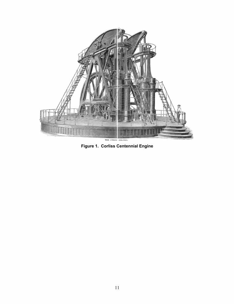
Machines using flywheels grew in power and size culminating in the massive stationary steam engines of the late 1800s. The largest engines, such as the Centennial Engine shown in Figure 1 [11], produced 1.04 MW (1 400 hp), stood more than 12 m (40 ft) tall, and employed flywheels 9 m (30 ft) in diameter.
While modern flywheels operate at a surface speed of 500 m s-1 or more, flywheels in stationary steam engines seldom ran at surface speed exceeding 20 m s-1 [12]. Consequently, since kinetic energy scales with the square of speed, a 50 t (where t is a metric tonne) flywheel from the industrial age would store just 5 kW h. In comparison, a modern flywheel in use today for stabilizing the electric grid weighs about 1 t [13] and stores more than 25 kW h of usable energy. In the era of the steam engine, flywheel bursts were fairly common, often due to a failure of a governor [14]. A particularly large failure could result in the destruction of the building in which it was housed [15].
11
Figure 1. Corliss Centennial Engine

12
4. THE DESIGN OF MODERN FLYWHEELS
Standalone flywheels systems are designed expressly for energy storage and power management. A number of attributes differentiate these systems from the flywheels used as engine components. With few exceptions, the flywheel power management system is electrically connected to the application that it serves. The flywheel rotor is generally located in its own dedicated housing which is evacuated or held at reduced pressure in order to minimize aerodynamic drag. The rotor will operate at high speed to make the best use of the rotor material. Charging and discharging events will take place over many revolutions and will usually involve a substantial change in the spin speed of the rotor.
The power delivered by the flywheel and the kinetic energy stored in the flywheel are specified independently. The degree of independence is considerable with flexibility in selecting flywheel discharge time spanning several orders of magnitude.
Since the ratio of energy to power has units of time, it is useful to express the capability of a flywheel in terms of output power that is provided for a specified duration. In one example, a flywheel system designed to serve a ridethrough application may provide 1 MW for three seconds. This system provides 0.8 kW h of usable energy. In a second example, a flywheel system designed for frequency regulation services may provide 100 kW for fifteen minutes. This system provides 25 kW h of usable energy. These two systems will have very different design criteria. The machine of the first example will have a powerful motor and will be optimized to minimize motor cost. The machine of the second example stores much more energy and will be optimized to minimize rotor cost.
Flywheels have inherently long cycle and calendar life. The material properties of the metals and composites used in flywheels are well understood and allow for a design life exceeding 106 cycles. The state of charge of a flywheel and its availability are known with high precision and accuracy. Individual modules in use today, range in energy capacity from a fraction of a kilowatt-hour to hundreds of kilowatt-hours.
13
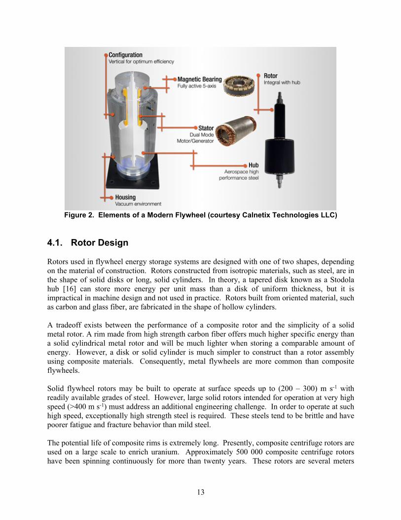
Figure 2. Elements of a Modern Flywheel (courtesy Calnetix Technologies LLC)
4.1. Rotor Design
Rotors used in flywheel energy storage systems are designed with one of two shapes, depending on the material of construction. Rotors constructed from isotropic materials, such as steel, are in the shape of solid disks or long, solid cylinders. In theory, a tapered disk known as a Stodola hub [16] can store more energy per unit mass than a disk of uniform thickness, but it is impractical in machine design and not used in practice. Rotors built from oriented material, such as carbon and glass fiber, are fabricated in the shape of hollow cylinders.
A tradeoff exists between the performance of a composite rotor and the simplicity of a solid metal rotor. A rim made from high strength carbon fiber offers much higher specific energy than a solid cylindrical metal rotor and will be much lighter when storing a comparable amount of energy. However, a disk or solid cylinder is much simpler to construct than a rotor assembly using composite materials. Consequently, metal flywheels are more common than composite flywheels.
Solid flywheel rotors may be built to operate at surface speeds up to (200 – 300) m s-1 with readily available grades of steel. However, large solid rotors intended for operation at very high speed (>400 m s-1) must address an additional engineering challenge. In order to operate at such high speed, exceptionally high strength steel is required. These steels tend to be brittle and have poorer fatigue and fracture behavior than mild steel.
The potential life of composite rims is extremely long. Presently, composite centrifuge rotors are used on a large scale to enrich uranium. Approximately 500 000 composite centrifuge rotors have been spinning continuously for more than twenty years. These rotors are several meters

14
long and operate at surface speeds in excess of 1000 m s-1. The design life of these rotors is 35 years. Flywheel rotors derived from centrifuge technology are expected to be capable of comparable calendar life and ten million deep discharge cycles [17].
4.2. Bearings
Bearings support the flywheel rotor while allowing it to spin freely. Bearing requirements tend to be more severe for flywheels than for other rotating machines and bearings are usually the life limiting element in a flywheel design. Flywheel rotors tend to be unusually heavy when compared to other rotating machines operating at comparable speed. The need to support the greater weight of the rotor leads to the use of larger bearings which have greater drag losses and inherently poorer life than smaller bearings [18]. Since the flywheel operates in vacuum or reduced pressure, thermal management and lubrication are also difficult.
The two most prevalent types of bearings found in flywheel systems are active magnetic bearings and ball bearings. Active magnetic bearings levitate and actively position the rotor. They are free from contact and therefore free from wear.
Ball bearings represent a simpler, more common, less expensive alternative to active magnetic bearings but are challenged by the life and load requirements of flywheels. For instance, a flywheel designed to operate at 270 Hz (16 000 RPM) will accumulate 1.7 x 10¹¹ revolutions over twenty years. But conventional bearing theory fails to predict reliable life beyond 1010 revolutions. Recent advances in ball bearing theory indicate that maintaining peak contact pressure between the ball and the bearing race below 2 000 MPa (300 000 psi) can increase rotation life by more than an order of magnitude over conventional theory [19]. In practice, permanent magnets or solenoid coils are often used in conjunction with ball bearings. This reduces load on the ball bearings allowing the use of smaller bearings and lower contact pressure thereby improving bearing life. To simplify design of the levitation system and manage bearing loads, most standalone flywheel systems are built using a vertical spin axis.
4.3. Motor/Generator
The standalone flywheel module is charged and discharged by an integral motor-generator. The motor may be integrated into the steel or composite rotor or may be attached to the rotor by a hub and shaft. A wide variety of motor types have been deployed including homopolar, synchronous reluctance, induction, as well as many types of permanent magnet machine. The selection of a motor type is usually dictated by consideration of thermal management of the flywheel rotor. As the rotor is surrounded by vacuum, removing heat from the rotor occurs through radiation to the housing and is ineffective unless high rotor temperature is allowed. Consequently, a goal of flywheel motor design is to minimize heat dissipated in the rotor. This is not a significant concern for steel rotors used in uninterruptable power supplies as the flywheel motor is operated only occasionally and little energy is deposited in the rotor. For carbon and glass composite rotors that will be cycled frequently, design for low on-rotor loss is critical and permanent magnet machines are usually used.

15
5. COST AND COMPARISON WITH OTHER TECHNOLOGIES
Cost is the deciding factor in the selection of one energy storage technology over another. Flywheels must compete with batteries and ultracapacitors on the basis of cost where cost is evaluated over the life of a system. For low cycle applications, such as electric vehicles, battery prices are already nearing the long sought goal of $100 (kW h)-1 (100 dollars per kilowatt hour) [20]. Flywheels are highly unlikely to achieve this incremental energy cost using reasonably foreseeable materials and subsystems.
However, applications requiring 106 cycles and a calendar life of decades are well served by flywheels as battery cycle life remains at least two orders of magnitude lower than this. In these applications, flywheels compete with ultracapacitors on the basis of the cost per unit energy delivered.
Ultracapacitors have a cycle life as high as 106 and an incremental energy cost that has declined to $20 000 (kW h)-1 [21]. In theory, ultracapacitors should be cost competitive at any power level for discharge times up to several seconds. However, current applications requiring short duration discharge (three seconds) in excess of 1 MW, such as electromagnetic aircraft launch and ridethrough backup power, are presently served by rotary systems.
The relative cost competitiveness of ultracapacitors, batteries, and flywheels may be presented in terms of power and discharge time. Flywheels are a cost effective solution for applications requiring power for more than several seconds and up to several or tens of minutes, particularly when high cycle life is required. For applications requiring less than 100 kW, balance of system costs make flywheels less cost competitive.
The figure below shows regions where flywheels, capacitors, and batteries are most cost effective. Also shown are the ratings of flywheel systems from a number of current manufacturers. The shaded area indicates the region of the parameter space where flywheels are particularly advantageous.
Beacon
Temporal Power
Piller
Williams/GKN
Powerthru
Calnetix
Active Power
PowerStore
10
100
1000
5 50 500
Power (kW)
Discharge Time (seconds)
CAPACITORS BATTERIES
FLYWHEELS
Figure 3. Flywheels, Capacitors and Batteries

16
Cost drivers for flywheel systems are spread out over a number of subsystems including the rotor, bearings, power electronics and the balance of system. The total cost of a flywheel system comprises three scalable cost centers.
a.) Elements that scale with stored energy: For a particular geometry and rotor material, rotor weight and cost scale with stored energy. Components and subsystems that scale with rotor weight include the bearings, the housing, and structural hardware.
b.) Elements that scale with power: For a flywheel system with an integral motor/generator, elements that scale with power include the motor itself, the motor drive, and electrical equipment.
c.) Balance of System: Balance of system includes the vacuum pump, sensors, telemetry, diagnostics, and controls and other components required for operation of the flywheel that do not scale with energy or power.
The cost for a complete flywheel system may be expressed as follows [1]:
𝐶 = 𝐴 ∗ 𝑃𝑜𝑤𝑒𝑟 + 𝐵 ∗ 𝐸𝑛𝑒𝑟𝑔𝑦 + 𝐶𝐵𝑂𝑆
Elements that scale with power, A, have a cost expressed in $ kW-1, elements that scale with stored energy, B, have a cost expressed in $ (kW h)-1, and balance of system costs, CBOS have units of dollars.
Flywheel systems in service today have costs spread across all three cost centers. There appears to be no reported instance of an existing system where the cost of the rotor exceeds 20% of the cost of the system. Consequently, it is not valid to scale flywheel system cost on the basis of dollars per kilowatt hour absent a consideration of the composition of flywheel system cost.
However, the incremental cost of per unit of stored energy is calculable for rotor materials. In order to reflect the high-cycling capability of flywheels, it is important to allow for a 50% reduction in strength typical in steel subjected to 106 cycles. The following table gives an approximation of the incremental cost of rotor material for high-cycle flywheel applications.
Material $ (kW h)-1 Mass (kW h)-1
Carbon Composite 1 200 1
1800 MPa (260 000 psi) steel 1 800 7x
1100 MPa (160 000 psi) steel 2 000 12x
600 MPA (90 000 psi) steel 4 000 24x
Table 1. Flywheel Rotor Material Cost per Unit Stored Energy

17
The first column refers to the yield strength of various grades of steel when new. The carbon composite values are based on filament wound construction using 4800 MPa (700 000 psi) fiber with 65% fiber fraction and proven safety factors for high cycle life [1]. It is important to recognize that this metric applies only to the incremental cost of increasing the mass of a rotor to store more energy. This metric does not reflect other costs such as the motor, bearings, and the housing that are generally greater than the cost of the rotor itself. The third column indicates the mass of a steel flywheel rotor relative to a carbon composite rotor storing the same energy when both are designed for a life of 106 cycles. A heavier rotor requires higher capacity bearings and a heavier, more costly housing. Therefore, not only does a carbon composite rotor have lower incremental cost per unit of stored energy, the balance of systems costs can be reduced as well.

18
6. APPLICATIONS
Applications for flywheels are viable when two conditions are met. First, the flywheel must represent a more cost effective solution than competing forms of energy storage. Second, a market must exist so that the deployment of a flywheel system results in an economic return. This section describes and estimates the scale of application areas where flywheels currently represent solutions that are technically effective and cost competitive. These include: grid-connected power management, industrial and commercial power management, pulsed power, uninterruptable power supplies and mobile applications
6.1. Grid Connected Power Management
Stationary, grid connected applications exist on the utility side of the electric meter. Here, the sale of services and products is highly regulated and a market for an energy storage solution only exists after being created by a regulatory agency. Flywheels are used in two such applications which are related: frequency regulation and management of ramping due to fluctuating renewable generating resources.
6.1.1. Frequency Regulation
A large electrical grid must operate at a nearly constant frequency in order for the generators to remain synchronized. When the amount of electricity consumed changes, generator output must be controlled to follow the load. For instance, if the load increases faster than a turbine generator can respond, the generator slows down, momentarily operating at lower frequency. If the load changes are severe enough, or if a large generating asset suddenly drops off-line, other generators may not remain synchronized and a wide spread power outage may occur.
Frequency regulation is provided by generators as an ancillary service to improve the stability of the grid. A power plant may sell the frequency regulation service to the grid operator in addition to selling electricity by operating slightly below peak power so that it may regulate up or down. In order to provide this service effectively, the power plant must be able to ramp up and down quickly, responding to a control signal from the grid operator that may change every few seconds or less. Flywheels are ideally suited to this application as they are capable of millisecond response times and nearly constant cycling.
Commercialization of energy storage for frequency regulation is realized through the construction of an energy storage plant. The plant is typically owned by a private entity rather than the utility and is typically installed at an existing substation to facilitate interconnection. Once commissioned, the private entity sells frequency regulation services to the grid operator.
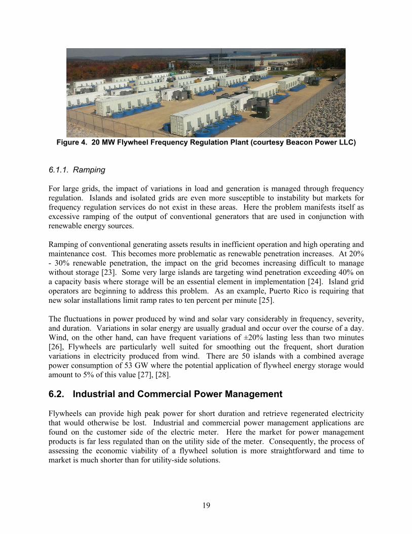
Beacon Power LLC pioneered the use of flywheels for frequency regulation with 20 MW plants located in Stephentown, New York and Hazel Township, Pennsylvania The Stephentown plant provides approximately 10% of New York’s overall frequency regulation needs [22].
19
Figure 4. 20 MW Flywheel Frequency Regulation Plant (courtesy Beacon Power LLC)
6.1.1. Ramping
For large grids, the impact of variations in load and generation is managed through frequency regulation. Islands and isolated grids are even more susceptible to instability but markets for frequency regulation services do not exist in these areas. Here the problem manifests itself as excessive ramping of the output of conventional generators that are used in conjunction with renewable energy sources.
Ramping of conventional generating assets results in inefficient operation and high operating and maintenance cost. This becomes more problematic as renewable penetration increases. At 20% - 30% renewable penetration, the impact on the grid becomes increasing difficult to manage without storage [23]. Some very large islands are targeting wind penetration exceeding 40% on a capacity basis where storage will be an essential element in implementation [24]. Island grid operators are beginning to address this problem. As an example, Puerto Rico is requiring that new solar installations limit ramp rates to ten percent per minute [25].
The fluctuations in power produced by wind and solar vary considerably in frequency, severity, and duration. Variations in solar energy are usually gradual and occur over the course of a day. Wind, on the other hand, can have frequent variations of ±20% lasting less than two minutes [26], Flywheels are particularly well suited for smoothing out the frequent, short duration variations in electricity produced from wind. There are 50 islands with a combined average power consumption of 53 GW where the potential application of flywheel energy storage would amount to 5% of this value [27], [28].
6.2. Industrial and Commercial Power Management
Flywheels can provide high peak power for short duration and retrieve regenerated electricity that would otherwise be lost. Industrial and commercial power management applications are found on the customer side of the electric meter. Here the market for power management products is far less regulated than on the utility side of the meter. Consequently, the process of assessing the economic viability of a flywheel solution is more straightforward and time to market is much shorter than for utility-side solutions.

20
6.2.1. Transit
Flywheels produced by Calnetix and URENCO have been demonstrated in a number of transit systems for trackside energy recovery [29]. In this application, the flywheel is installed at a station or a transit system substation. The flywheel captures energy recovered through regenerative braking and uses this energy to accelerate the train as it leaves its stop. This allows for heavier and longer trains without increasing transmission or distribution line capacity. In order to mitigate voltage sag or increase transit system capacity in an existing system without using energy storage, a new substation has to be installed. Flywheel energy storage installed at a transit station can provide the same mitigation of voltage sag as a new substation but in a small footprint with no new utility feed and at a much lower cost. Given the high rate of charge-discharge cycles, flywheels are particularly well suited for this application.
Globally, 190 metro systems operate 9 477 stations and over 11 800 km of track [30]. Using energy storage to recover energy lost in braking has the potential to reduce metro rail electricity consumption on the order of 10% [31] while achieving energy cost savings of $90 000 per station [32]. When installed in regions where the utility tariff structure includes demand charges, additional savings of up to $250 000 per station per year are attainable [33]. In studies and tests to date, trackside storage sized to provide 1 MW – 3 MW of launch power or energy recovery per station was found to be an effective rating for the metro rail application [34].
6.2.2. Mining
Flywheels have potential application in mining. Open Pit mines around the world use electrically powered draglines to excavate material. The load profile of a dragline is cyclic, highly non-uniform, and produces regenerated electricity which is generally lost. During the lifting phase, peak loads of 6 MW are typical. Lowering the load into a conveyance regenerates as much as 3 MW. This cycle repeats approximately once per minute continuously.
In one instance, the Usibelli Coal mine in Healy, Alaska operates a 6 MW dragline that is fully electric and is connected to the Golden Valley Electric Association (GVEA) grid. The impact of the fluctuating load was so severe that routine dragline operation caused the lights of other GVEA customers to flicker. Since 1982 the Usibelli mine has operated a flywheel to smooth the load drawn by the dragline. The 40 t flywheel consists of three one foot thick, eight foot diameter steel plates and is connected to the GVEA grid in parallel with the dragline, successfully mitigating the problem [35].
6.3. Pulsed Power
Pulsed power is the collection of energy at a steady rate followed by the rapid, high power discharge of the energy into the application. Flywheels are well suited for this use and may be found in military, research and motive power applications.

21
6.3.1. EMALS
A key military application is the use of flywheels to energize Electromagnetic Aircraft Launch (EMALS) [36] on aircraft carriers, in order to replace steam powered catapults. Steam catapults are large, heavy and inefficient. Heretofore, each launch consumed 615 kg (1 350 lb) of steam produced by the aircraft carrier’s nuclear reactor.
The linear synchronous motor of the EMALS system is designed to launch heavier aircraft using much less energy. The linear motor is powered by alternators with significant inertia. Each alternator comprises an axial field permanent magnet motor with dual stators. The alternator’s rotor disk serves as the energy storage component and the field source during power generation. Average power from the ship’s electrical system is fed into the alternator between launch events. The system is sized to charge fully in 45 s. During a launch event, the energy stored in the rotors is released in a pulse lasting about 2 s. Peak alternator output is 81.6 MW when discharged into an impedance matched load. When fully charged, the EMALS rotors store 121 MJ (33.6 kW h) of extractable energy at a maximum speed of 160 Hz (6 400 RPM). The total stored energy is much higher as the rotor speed only decreases by about 25% during a launch event.
6.3.2. Research Facilities
Flywheels have been used to provide pulsed power to large research facilities such as the Joint European Torus (JET), Oxfordshire, England, which is the largest and most powerful tokamak currently in use. JET has been in operation since in 1983. A single plasma pulse at JET requires peak power of 1000 MW and occasionally more. On a typical day, 22 tests are conducted. JET draws power from the grid continuously, charging two enormous steel flywheels. The flywheels provide power for each test.
Each of the two JET flywheels has a diameter of about 9 m and weighs 775 t. At full speed the rotors spin at 3.7 Hz (225 RPM) and attain a tip speed of around 100 m s-1. Between shots, the wheels are accelerated from half speed to full speed over a period of 540 s (9 minutes) using 8.8 MW motors. During a 20 s shot, each flywheel can discharge 700 kW h of energy at a peak power of 500 MW [37].
6.3.3. Roller Coaster Launch
Traditionally, roller coaster launch systems use a chain drive to bring the train to the top of the first hill followed by the familiar plunge. In a new class of coasters, energy is accumulated in a flywheel and then used to rapidly accelerate the train using electromagnetic, hydraulic, and friction wheel propulsion [38]. The Incredible Hulk roller coaster at Universal’s Island of Adventure theme park in Orlando, Florida is a noteworthy example. The Incredible Hulk uses a friction wheel drive system to accelerate the train at 1 G up an incline, reaching a speed at the top of 18 m s-1 (40 mph). The launcher comprises 230 motors powering wheels that grip a rail attached to the bottom of the train. The launch event draws 8 MW for 2 s and is repeated every 90 s. In order to avoid disruption to the local utility, several 4500 kg (10 000 lb) flywheels charge continuously at about 200 kW and then discharge at 8 MW to launch the train [39].

22
6.4. Uninterruptible Power Supplies (UPS)
Flywheel systems are in global use providing temporary backup electrical power. The purpose of the flywheel in this application is to support the load of a critical facility or system during a power outage until backup diesel generators can be brought up to speed and synchronized. Flywheels compete directly with batteries and offer the advantages of much longer service life and the avoidance of the need to periodically replace and recycle the batteries. Here flywheels are implemented in one of two ways.
When used a standalone energy storage device, the system is referred to as a flywheel UPS. The flywheel provides electrical power to a DC bus and an inverter converts this into AC electricity to power the load. In this application, the flywheel replaces or augments a battery. Discharge times of ten’s of seconds are typical. Rotors in flywheel UPS systems generally spin about a vertical axis in vacuum or reduced pressure.
Rotary UPS are variously known as ridethrough systems, engine coupled UPS, or diesel rotary uninterruptible power supplies (DRUPS). A typical rotary system comprises a diesel generator, an inductive coupling with a substantial moment of inertia, and an alternator all mounted coaxially on a common base frame. A clutch may be located between the inductive coupling and the generator. During an outage, kinetic energy stored in the inductive coupling drives the alternator to support the load while the diesel generator starts. Power from the generator may be available in as little as 3 s after an outage begins. Rotary UPS are large, the smallest having a rating around 1 MW.
The global market for UPS systems is on the order of $8x10⁹ - $10x109 ($8B - $10B) per year. Rotary systems account for about 5% of the total UPS market. However, when only large systems (>2MW) are considered, Rotary UPS account for 35% of the market [40]. In Europe, where Rotary UPS are well established, half of all new UPS installations that are rated at more than 1 MW are Rotary UPS [41].
6.5. Mobile
Mobile applications are those in which the flywheel is installed in a vehicle. Flywheel energy storage has been demonstrated in buses and may now be found in materials handling and motorsport.
6.5.1. Materials Handling
Materials handling involves the intermittent, repeatable application of power to move loads. Often, the peak power required to move a load is much greater than the average power of the process and there is no convenient way to recover energy while lowering a load. Flywheels are well suited for this application as load duration is short and repeated frequently. One application is found in Rubber Tired Gantry Cranes (RTGs). Approximately 8,000 RTGs operate in container terminals around the world. While ship-to-shore cranes are grid connected, RTG cranes are free to move about the terminal and are often powered by an onboard diesel genset. Without energy storage, the non-uniform load results in inefficient operation and high emissions.

23
Figure 5. Flywheels Installed in RTG (courtesy Calnetix Technologies LLC)
Since 2006, flywheels produced by Calnetix have been deployed in RTGs to move shipping containers. Lifting a container typically draws about 240 kW for around ten seconds. The power to perform the lift is provided by the flywheel allowing the genset to operate at more uniform output. During lowering, the hoist motors function as generators, returning energy to the electrical system to be stored in the flywheels for reuse. The flywheel system has been demonstrated to reduce fuel consumption by 32%-38% [42], nitrous oxide emissions by 26%, and particulate emissions by 67% [43].
6.5.2. Motorsport
Since the late 2000s hybrid propulsion systems have powered the cars in top-tier motorsport beginning with Formula 1 followed by the highest class of WEC (World Endurance Championship) racing: the Le Mans LMP1 series. Hybrid powertrains improve fuel efficiency reducing the number of pit stops required to complete a 24 h (24-hour) race that covers approximately 5000 km (3000 miles). Williams Hybrid Power (WHP) pioneered the use of flywheel energy storage in motorsport. WHP flywheels were used successfully in the Audi R18 e-Tron LMP1s that won at Le Mans in 2012, 2013 and 2014 [44].

24
6.5.3. Spacecraft
Throughout the history of space flight, flywheels have been used to stabilize and point spacecraft of all types. These flywheels are implemented as Control Moment Gyros (CMGs) or reaction wheels, which are also referred to as momentum wheels. A reaction wheel may have a nominal fixed spin speed or a nominal spin speed of zero. When torque is applied to the wheel, the opposing moment rotates the spacecraft. Reaction wheels are useful when the spacecraft must be rotated by a very small amount, such as when pointing at a star or target. Reaction wheels are more common in smaller spacecraft. In contrast, CMGs spin continuously creating gyroscopic moment. Mounted in motorized gimbals, tilting the spin axis of the CMG with respect to the inertial frame of the spacecraft can produce large steering torque with very little power. CMGs are found in spacecraft of all sizes, up to and including the International Space Station.
For either reaction wheels or CMGs, the use of an inertial wheel shifts the burden of attitude control from limited propellant to inexhaustible solar power. Thousands of inertial wheels have flown and a mature industry exists [45].

25
7. OUTLOOK
As a component of rotating machinery, the continued use of flywheels is both certain and unremarkable. As electrically connected energy storage systems, flywheels must compete with batteries and ultracapacitors on the basis of cost.
For low cycle applications, such as electric vehicles, flywheels are unlikely to achieve the already low incremental energy cost of batteries [20]. However, applications requiring 106 cycles and a calendar life of decades may continue to be well served by flywheels as battery cycle life remains at least two orders of magnitude lower than this. The extent to which the use of flywheels will expand or decline will depend on trends in cost reduction for flywheels and for the various competing technologies.
Flywheels will benefit as other industries drive increasing performance and declining cost in materials and electronics. The materials and processes currently used to produce flywheel rotors are highly mature and large cost reductions are unlikely. However, given the geometric impact of rotor material performance on flywheel cost, the development of potentially transformative materials, perhaps carbon nanotube composite, might not only substantially improve the energy per unit mass of the rotor but also lead to much smaller and less costly bearings and housings.
The increasing use of energy storage and electric motors in hybrid and electric vehicles is already impacting power electronics supply chain used by flywheel developers for the motor drive and magnetic bearings. To the benefit of flywheels, motor drive power electronics costs have dropped dramatically over the last decade and are approaching $5 kW-1 [46].
Given the increasing need in areas where flywheels are already in use combined with performance and cost trends in the underlying technology, flywheels should remain a competitive energy storage solution for short duration, high cycle applications for the foreseeable future.

26

27
8. REFERENCES
[ ] D. Bender, “Flywheels,” The World Scientific Handbook of Energy, Vol 4., G. Crawly editor, World Scientific, 2015.
[2] W. C. Young, R.G. Budynas, Roark’s Formulas for Stress and Strain, 7th edition, McGraw Hill, New York, 2001 pp. 746.
[3] W. C. Young, R.G. Budynas, Roark’s Formulas for Stress and Strain, 7th edition. McGraw Hill, New York, 2001 pp. 745
[4] “Potter’s Wheel,” New World Encyclopedia, http://www.newworldencyclopedia.org/entry/Potter's_wheel, retrieved 9/25/2014.
[5] V. Bryant, “The Origin’s of the Potter’s Wheel,” Ceramics Today, http://www.ceramicstoday.com/articles/potters_wheel.htm, retrieved 9/25/2014.
[6] J. B. Chang, D. A. Christopher, J. K. H. Ratner, “Flywheel Rotor Safe-Life Technology: Literature Search Summary,” Diane Publishing, Darby PA, USA, 2002 ix.
[7] H. Hodges, “Technology in the Ancient World,” Barnes and Noble, New York, 1992., p 47.
[8] E. W. Barber, “Prehistoric Textiles: The Development of Cloth in the Neolithic and Bronze Ages with Special Reference to the Agean,” Princeton University Press, Princeton USA, 1991, pp. 41 – 44.
[9] A. Pacey, “Technology in World Civilization: A Thousand-Year History,” MIT Press, Cambridge, MA, 1991.
[10] H. W. Dickinson, “A Short History of the Steam Engine,” Cambridge University Press, Cambridge, United Kingdom, 2011, pp. 79-82.
[11] United States Centennial Commission, F. A. Walker, Ed., International Exhibition, 1876, Reports and Awards Group XV, Lippincott, Philadelphia, 1877; Figure 53 insert between pages 96-97.
[12] Industry: A Magazine Devoted to Science, Engineering, and the Mechanic Arts, Especially on the Pacific Coast, Volume 5, Industrial Publishing Company 1892, p 776.
[13] “Carbon Fiber Flywheels,” Beacon Power Corporation, http://beaconpower.com/carbon-fiber-flywheels/, retrieved October 2, 2014.
[14] Insurance Engineering, Volume 10, Insurance Press 1905, p. 384, p. 579.
[15] http://www.farmcollector.com/steam-traction/100-years-ago-in-american-machinist.aspx#axzz3DIFKslUY, retrieved 9/27/14.

28
[16] G. Genta, “Flywheel Energy Storage,” Butterworths, London United Kingdom, 1985.
[17] G. Gardiner, “Composite Flywheels: Finally Picking up Speed?,” Composites World, March 4, 2014. http://www.compositesworld.com/blog/post/composite-flywheels-finally-picking-up-speed, retrieved October 6, 2014.
[18] H. Hertz, "Contact Between Solid Elastic Bodies," Journ. Für reine und angewandte Math. 92, 1882.
[19] Life – A New Life Theory, Part 5 – Technical Guide, “Super Precision Bearings,” NSK Motion and Controls, file e1245f.pdf, pp. 138-144 http://www.jp.nsk.com/app01/en/ctrg/index.cgi?rm=pdfView&pno=e1254f, retrieved 9/27/2014.
[20] Z. Shahan, “Are EV Battery Prices Much Lower Than We Think? Under $200/kWh.” Clean Technica, http://cleantechnica.com/2014/01/07/ev-battery-prices-much-lower-think/, retrieved 10/9/14.
[21] Pricing information for Maxwell and Ioxus cells and modules obtained by the author, March 2014.
[22] Beacon Power Stephentown Advanced Energy Storage Case Study, Clean Energy Action Project, http://www.cleanenergyactionproject.com/CleanEnergyActionProject/CS.Beacon_Power_Stephentown_Advanced_Energy_Storage___Energy_Storage_Case_Study.html, retrieved 10/7/14.
[23] International Renewable Energy Agency, “Electricity Storage and Renewables for Island Power,” May 2012.
[24] EirGrid, System Operator for Northern Ireland, “All-Island Generating Capacity Statement 2012 – 2021.”
[25] V. Gevorgian, S. Booth, “Review of PREPA Technical Requirements for Interconnecting Wind and Solar Generation,” National Renewable Energy Laboratory report, NREL/TP-5D00-57089, November 2013.
[26] V. Gevorgian, D. Corbus. “Ramping Performance Analysis of the Kahuku Wind –Energy Battery Storage System,” National Renewable Energy Laboratory report, NREL/MP-5D00-59003, November 2013.
[27] http://en.wikipedia.org/wiki/List_of_countries_by_electricity_consumption, retrieved 9/27/14.
[28] http://en.wikipedia.org/wiki/List_of_islands_by_population, retrieved 9/27/14.

29
[29] C. Tarrant, “Kinetic Energy Storage Wins Acceptance,” Railway Gazette, April 1, 2004, http://www.railwaygazette.com/news/single-view/view/kinetic-energy-storage-wins-acceptance.html, retrieved 10/7/14.
[30] http://en.wikipedia.org/wiki/List_of_metro_systems, retrieved 10/7/14.
[31] http://www.abb.com/cawp/seitp202/265455d72a797481c1257b59003b8600.aspx, retrieved 10/7/14.
[32] M. P. Schroeder, J. Yu, D. Teumin, Guiding the Selection & Application of Wayside Energy Storage Technologies for Rail Transit and Electric Utilities, Transit Cooperative Research Program, Transportation Research Board, Contractor’s Final Report for TCRP Project J-6/Task 75 Submitted November 2010.
[33] APTA whitepaper, “SEPTA Recycled Energy Optimization Project with Regenerative Braking Energy Storage,” Jacques Poulin, Product Manager – Energy Storage, ABB Inc., Montreal.
[34] P. McMullen, “Green Ovations: Innovations in Green Technologies, Reducing Peak Power Demand with Flywheel Technology,” Electric Energy Online Jan/Feb 2013, http://www.electricenergyonline.com/show_article.php?mag=&article=680, retrieved 10/7/14.
[35] Usibelli Coal Mine Flywheel – Alaska Energy Wiki, http://energy-alaska.wikidot.com/usibelli-flywheel, retrieved 9/24/2014.
[36] GlobalSecurity.Org, http://www.globalsecurity.org/military/systems/ship/systems/emals.htm, retrieved 9/24/14.
[37] M. Huart, L. Sonnerup, JET Flywheel Generators, Proceedings of the Institution of Mechanical Engineers, Part A: Journal of Power and Energy, 200 (1986) 295-300.
[38] Bleck & Bleck Architects LLC, http://bleckarchitects.com/2014/08/flywheel-launched-coaster/ retrieved April 3, 2015.
[39] “Total Immersion: Theme Park for the 21st Century,” Orlando, Florida: USA Networks, https://www.youtube.com/watch?v=VNDlM-1gvMY retrieved April 3, 2015
[40] “Kinetic Energy Storage vs. Batteries in Data Centre Applications,” Hitec Power, http://www.datacentre.me/downloads/Documents/KINETIC%20ENERGY%20STORAGE%20VS%20BATTERIES%20IN%20DATA%20CENTRE%20UPS%20APPLICATIONS..pdf, retrieved 10/9/14.
[41] G. Gagliano, Applications Director, S&C Electric Company, private communication, March 2014.

30
[42] “Flywheel Energy Storage for Rubber Tired Gantry Cranes.” Green Car Congress, April 9, 2009, http://www.greencarcongress.com/2009/04/flywheel-energy-storage-system-for-rubber-tired-gantry-cranes.html, retrieved 10/8/14.
[43] M. Flynn, P. McMullen, O. Solis, “Saving Energy Using Flywheels,” IEEE Industry Applications Magazine, (Nov/Dec 2008) 69-73.
[44] A. Cotton, “Audi R18 (2014),” Racecar Engineering, June 1, 2014.
[45] R. Votel, D. Sinclair, “Comparison of Control Moment Gyros and Reaction Wheels for Small Earth-Observing Satellites,” 26th Annual AIAA/USU Conference on Small Satellites.
[46] S. Rogers, “Advanced Power Electronics and Electric Motors R&D,” US DOE Presentation, May 14, 2013, http://energy.gov/sites/prod/files/2014/03/f13/ape00a_rogers_2013_o.pdf, retrieved 10/9/14.

31
DISTRIBUTION
1 ElsevierProfessor Trevor LetcherLaurel HouseFossewayStratton on the FosseBA3 4QNTel: 01761 [email protected]
1 MS 0330 Georgia Artery 00427
1 MS 9154 Donald A. Bender 00427
1 MS0899 Technical Library 9536 (electronic copy)

32
