fm delievered
DESCRIPTION
school workTRANSCRIPT
FREQUENCY MODULATION

INTRODUCTION• 3 properties of an analog signal can be
modulated by information signal:
oAmplitude - - -> produce AMoFrequency - - - > produce FMoPhase - - - > produce PM
• FM & PM are forms of angle modulation and often referred as frequency modulation.

FM VS AMFM is considered to be superior to AM.Transmission efficiency:AM use linear amplifier to produced the final RF
signal.FM has constant carrier amplitude so it is not
necessary to use linear amplifier.Fidelity (capture effect):The stronger signal will be capture and eliminate the
weaker.In AM, the weaker signal can be heard in the
background.Noise immunity (noise reduction):Constant carrier amplitude.FM receiver have limiter circuit
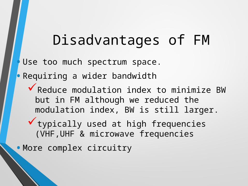
Disadvantages of FM• Use too much spectrum space.• Requiring a wider bandwidthReduce modulation index to minimize BW but
in FM although we reduced the modulation index, BW is still larger.typically used at high frequencies (VHF,UHF &
microwave frequencies• More complex circuitry
ANGLE MODULATION
( ) ( )mt F v t
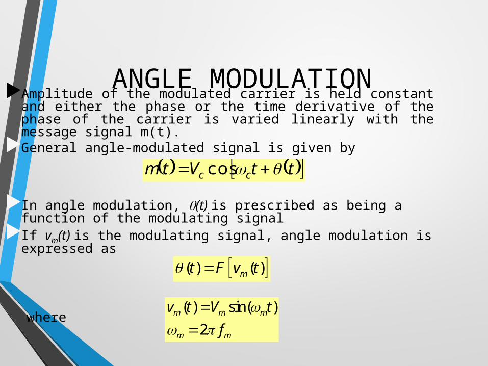
Amplitude of the modulated carrier is held constant and either the phase or the time derivative of the phase of the carrier is varied linearly with the message signal m(t).
General angle-modulated signal is given by
In angle modulation, (t) is prescribed as being a function of the modulating signal
If vm(t) is the modulating signal, angle modulation is expressed as
where ( ) sin( )2
m m m
m m
v t V tf
ttVtm cc cos

FM OR PM ?
• Both must occur whenever either form of angle modulation is performed.
FMFM PMPMInstantaneous frequencyInstantaneous frequency of of the carrier is varied from the carrier is varied from its reference value by an its reference value by an amount proportional to the amount proportional to the modulating signal modulating signal amplitudeamplitude
Freq. carrier - - - > directly Freq. carrier - - - > directly variedvariedPhase carrier - - -> Phase carrier - - -> indirectly variedindirectly varied
Phase anglePhase angle of the carrier of the carrier is varied from its reference is varied from its reference value by an amount value by an amount proportional to the proportional to the modulating signal modulating signal amplitudeamplitude
Phase carrier - - - > directly Phase carrier - - - > directly variedvariedFreq. carrier - - -> Freq. carrier - - -> indirectly variedindirectly varied

Figure 4.1 : Frequency deviation
∆f ∆f
fc-∆f fc fc+∆f f
-Vm 0 +Vm
vm(t) = Vm cos 2πfmt
2∆f

MATHEMATICAL ANALYSIS
instantaneous frequency deviation '( ) rad/s'( ) rad/s cycleor Hz
2 rad/cycle s
tt
• Instantaneous frequency deviationInstantaneous change in the frequency of the carrier
and is defined as the first time derivative of the instantaneous phase deviation
• Instantaneous frequencythe precise frequency of the carrier at any given
instant of time and is defined as the first time derivative of the instantaneous phase
instantaneous frequency ( ) ( )
'( ) rad/s
i c
c
dt t tdt
t

instantaneous frequency ( )
rad cyclesand ( ) 2 '( ) 2 '( ) rad/scycle s
i
i c c
f t
t f t f t
• Substituting 2fc for c gives
• Frequency modulation is angle modulation in which the instantaneous frequency deviation, ’(t), is proportional to the amplitude of the modulating signal, and the instantaneous phase deviation is proportional to the integral of the modulating signal voltage.

DEVIATION SENSITIVITY
rad/sVfk
V
For modulating signal vm(t), the frequency modulation are
frequency modulation = ’(t) = kfvm(t) rad/s
where kf are constant and are the deviation sensitivities of the frequency modulator.
Deviation sensitivities are the output-versus-input transfer function for the modulators, which gave the relationship between what output parameter changes in respect to specified changes in the input signal.
frequency modulator,

FREQUENCY MODULATION (FM)
( ) sin ( )
sin '( )
sin ( )
sin sin ( )
sin cos ( )
FM c c
c c
c c f m
c c f m m
f mc c m
m
v t V t t
V t t dt
V t k v t dt
V t k V t dt
k VV t t
• Variation of d/dt produces Frequency Modulation
• Frequency modulation implies that d/dt is proportional to the modulating signal.
• This yields
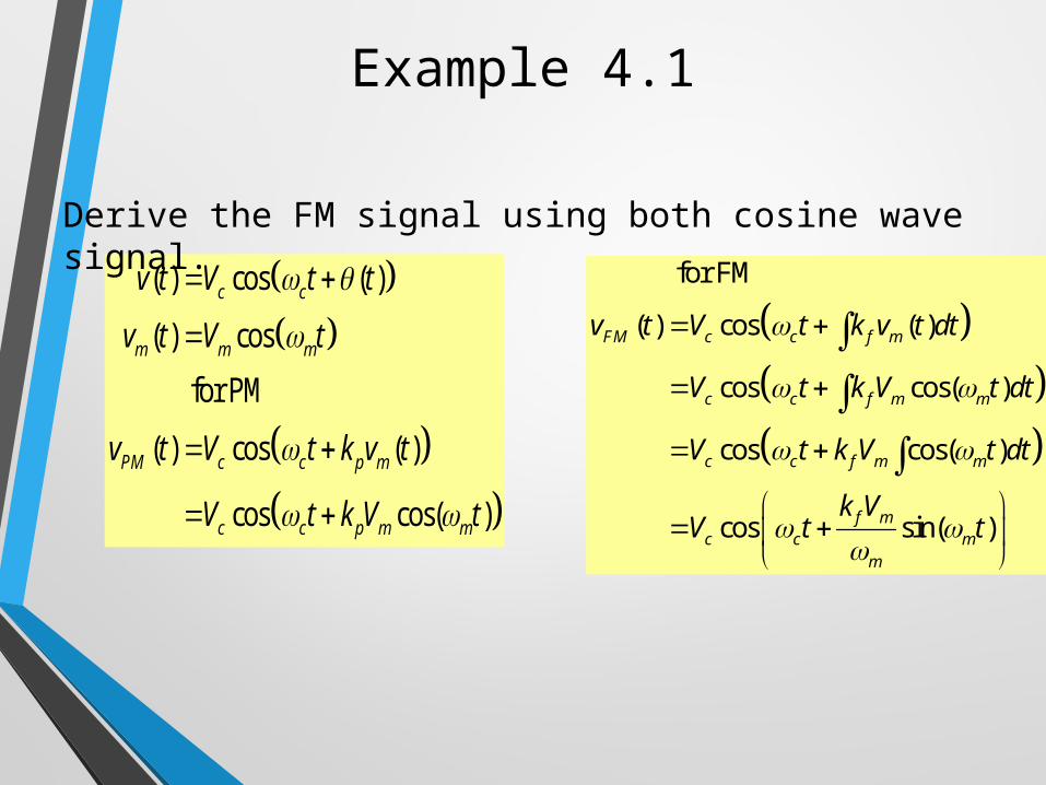
Example 4.1
( ) cos ( )
( ) cos
for PM
( ) cos ( )
cos cos( )
c c
m m m
PM c c p m
c c p m m
v t V t t
v t V t
v t V t k v t
V t k V t
for FM
( ) cos ( )
cos cos( )
cos cos( )
cos sin( )
FM c c f m
c c f m m
c c f m m
f mc c m
m
v t V t k v t dt
V t k V t dt
V t k V t dt
k VV t t
Derive the FM signal using both cosine wave signal.

Figure 4.2: Phase and Frequency modulation ; (a) carrier signal (b) modulating signal (c) frequency modulated wave (d) phase modulated wave
FM WAVEFORMFM WAVEFORM

Carrier amplitude remains constant Carrier frequency is changed by the modulating signal.amplitude of the information signal varies, the carrier
frequency shift proportionately.modulating signal amplitude increases, the carrier frequency
increases.modulating signal amplitude varies, the carrier frequency
varies below and above it normal center or resting, frequency with no modulation.
The amount of the change in carrier frequency produced by the modulating signal known as frequency deviation fd.Maximum frequency deviation occurs at the maximum
amplitude of the modulating signal.The frequency of the modulating signal determines the
frequency deviation rate
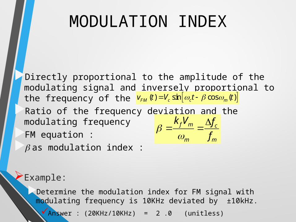
MODULATION INDEX
Directly proportional to the amplitude of the modulating signal and inversely proportional to the frequency of the modulating signalRatio of the frequency deviation and the modulating
frequencyFM equation : as modulation index :
Example: Determine the modulation index for FM signal with modulating
frequency is 10KHz deviated by ±10kHz.Answer : (20KHz/10KHz) = 2 .0 (unitless)
The total frequency change, 10kHz x 2 is called the carrier swing
( ) sin cos ( )FM c c mv t V t t
f m c
m m
k V ff

Example: • a simple transmitter with an assigned rest frequency
of 100MHz deviated by a ±25kHz, the carrier changes frequency with modulation between the limits of 99.975MHz and 100.025MHz
• The total frequency change, 25kHz x 2 is called the carrier swing
• Table 1 display the transmission band that use FM and the legal frequency deviation limit for each category
• Deviation limits are based on the quality of the intended transmissions, wider deviation results in higher fidelity
• The frequency deviation is a useful parameter for determining the bandwidth of the FM-signals

Specifications for transmission of FM signal
Table 1 display the transmission band that use FM and the legal Table 1 display the transmission band that use FM and the legal frequency deviation limit for each categoryfrequency deviation limit for each category
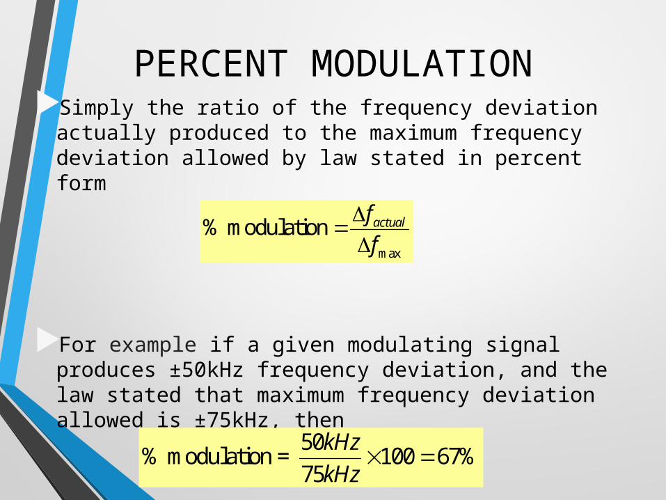
PERCENT MODULATIONSimply the ratio of the frequency deviation
actually produced to the maximum frequency deviation allowed by law stated in percent form
For example if a given modulating signal produces ±50kHz frequency deviation, and the law stated that maximum frequency deviation allowed is ±75kHz, then
max
% modulation actualff
50% modulation = 100 67%75
kHzkHz

Example 4.2A 1 MHz carrier freq with a measured sensitivity of 3 kHz/V is modulated with a 2 V, 4 kHz sinusoid. Determine
1. the max freq deviation of the carrier2. the modulation index3. the modulation index if the modulation
voltage is doubled4. the modulation index for
vm(t)=2cos[2π(8kHz)t)]V5. express the FM signal mathematically for
a cosine carrier & the cosine-modulating signal of part 4. Carrier amplitude is 10V


FM RADIO FREQUENCY
• Commercial radio FM band, 88MHz – 108MHz• Each station allotted to a frequency deviation
of ±75kHz (150 carrier swing) and 25kHz of guard band added above and below the carrier frequency swing
• Total bandwidth is 200kHz• Therefore, maximum of 100 stations can be
made available

FREQUENCY ANALYSIS OF FM
WAVES

Tabulated value for Bessel Function for the first kind of the nth order
BESSEL TABLE,

The first column gives the modulation , while the first row gives the Bessel function.
The remaining columns indicate the amplitudes of the carrier and the various pairs of sidebands.
Sidebands with relative magnitude of less than 0.001 have been eliminated.
Some of the carrier and sideband amplitudes have negative signs. This means that the signal represented by that amplitude is simply shifted in phase 180 (phase inversion).
The spectrum of a FM signal varies considerably in bandwidth depending upon the value of the modulation index. The higher the modulation index, the wider the bandwidth of the FM signal.
With the increase in the modulation index, the carrier amplitude decreases while the amplitude of the various sidebands increases. With some values of modulation index, the carrier can disappear completely.

Bessel Function, Jn(m) vs m
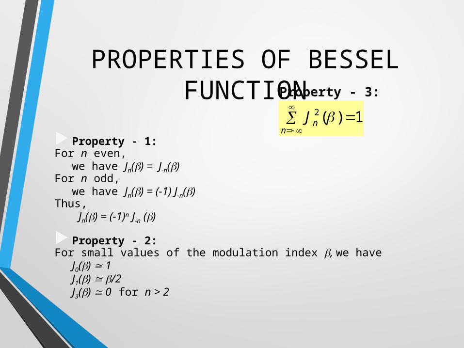
PROPERTIES OF BESSEL FUNCTION
Property - 1:For n even,
we have Jn() = J-n() For n odd,
we have Jn() = (-1) J-n() Thus,
Jn() = (-1)n J-n () Property - 2:For small values of the modulation index , we have
J0() 1J1() /2J3() 0 for n > 2
Property - 3:2 ( ) 1n
nJ

AMPLITUDE SPECTRUM
Amplitude spectrum of different value of

FM BANDWIDTH The total BW of an FM signal can be determined by
knowing the modulation index and Bessel function.
N = number of significant sidebandsfm = modulating signal frequency (Hz)
Another way to determine the BW is use Carson’s ruleThis rule recognizes only the power in the most
significant sidebands with amplitude greater than 2% of the carrier.
NfBW m2
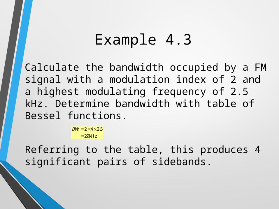
Example 4.3
2 4 2.520kHz
BW
Calculate the bandwidth occupied by a FM signal with a modulation index of 2 and a highest modulating frequency of 2.5 kHz. Determine bandwidth with table of Bessel functions.
Referring to the table, this produces 4 significant pairs of sidebands.
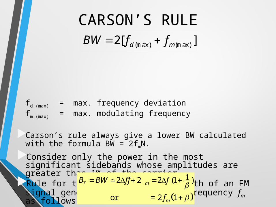
CARSON’S RULE
fd (max) = max. frequency deviationfm (max) = max. modulating frequency
Carson’s rule always give a lower BW calculated with the formula BW = 2fmN.Consider only the power in the most significant
sidebands whose amplitudes are greater than 1% of the carrier.Rule for the transmission bandwidth of an FM signal
generated by a single of frequency fm as follows:
12 2 2 (1 )
or = 2 1
T m
m
B BW f f f
f
][2 (max)(max) md ffBW

Example 4.4
For an FM modulator with a modulation index = 1, a modulating signal vm(t) = Vmsin(2π1000t) and unmodulated carriervc(t) = 10sin(2π500kt), determine
a)Number of sets of significant sidebandb)Their amplitudec)Then draw the frequency spectrum showing their relative amplitudes

Example 4.5
For an FM modulator with a peak freq deviation Δf = 10kHz, a modulating signal freq fm= 10kHz, Vc =10V and 500kHz carrier, determinea)Actual minimum bandwidth from the Bessel function tableb)Approximate minimum bandwidth using Carson’s rulec)Plot the output freq spectrum for the Bessel approximation
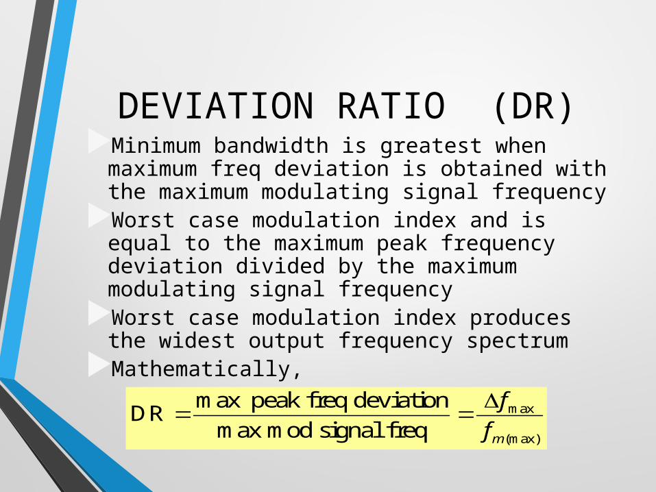
DEVIATION RATIO (DR)Minimum bandwidth is greatest when
maximum freq deviation is obtained with the maximum modulating signal frequencyWorst case modulation index and is equal
to the maximum peak frequency deviation divided by the maximum modulating signal frequencyWorst case modulation index produces the
widest output frequency spectrumMathematically,
max
(max)
max peak freq deviationDRmax mod signal freq m
ff

Example 4.6
• Determine the deviation ratio and bandwidth for the worst case (widest bandwidth) modulation index for an FM broadcast band transmitter with a maximum frequency deviation of 75kHz and a maximum modulating signal frequency of 15kHz
• Determine the deviation ratio and maximum bandwidth for an equal modulation index with only half the peak frequency deviation and modulating signal frequency
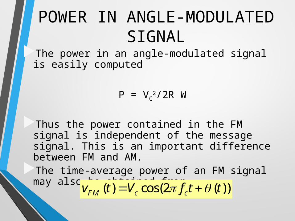
POWER IN ANGLE-MODULATED SIGNAL
The power in an angle-modulated signal is easily computed
P = VC2/2R W
Thus the power contained in the FM signal is independent of the message signal. This is an important difference between FM and AM. The time-average power of an FM signal may
also be obtained from ( ) cos(2 ( ))FM c cv t V f t t

Example 4.7
An FM signal is given as vFM(t)=12cos[(6π106t) + 5sin(2π x 1250t)] V. Determinea. freq of the carrier signalb. freq of the modulating signalc. modulation indexd. freq deviatione.power dissipated in 10 ohm resistor.

Example 4.8
Determine the unmodulated carrier power for the FM modulator given that =1, Vc=10 V, R = 50 Ω. Then, determine the total power in the angle-modulated wave.
Solution:
not exactly equal because values in Bessel table have been rounded off.

Example 4.9An FM signal expressed asis measured in a 50 ohm antenna. Determine the following :-a.total powerb.modulation indexc.peak freq deviationd.modulation sensitivity if 200 mV is required to achieve part ce.amplitude spectrumf. bandwidth (99%) and approximate bandwidth by Carson’s ruleg.power in the smallest sideband of the 99% BWh.total information power
)102sin5.0102cos(1000)( 47 tttvFM

Example 4.10
An FM signal with 5W carrier power is fluctuating at the rate of 10000 times per second from 99.96 MHz to 100.04 MHz. Finda.carrier freqb.carrier swingc. freq deviationd.modulation indexe.power spectrum

Example 4.11
In an FM transmitter, the freq is changing between 100 MHz to 99.98 MHz, 400 times per seconds. The amplitude of the FM signal is 5 V, determine :-1.carrier and modulating freq2.carrier freq swing3.amplitude spectrum4.bandwidth by using Bessel Table and Carson’s
rule5.average power at the transmitter if the modulator carrier power is 5 W.

FM SIGNAL GENERATION•They are two basic methods of generating frequency-Modulated signals:•Direct Method• Indirect Method
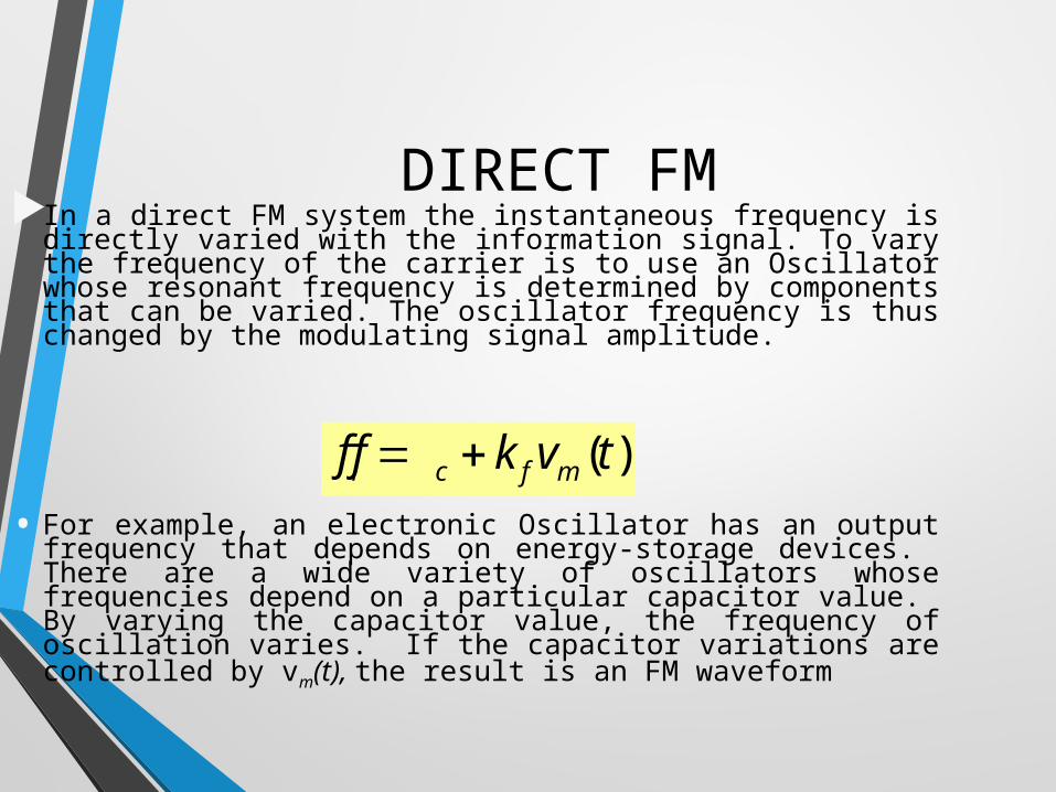
DIRECT FM
( )i c f mf f k v t
In a direct FM system the instantaneous frequency is directly varied with the information signal. To vary the frequency of the carrier is to use an Oscillator whose resonant frequency is determined by components that can be varied. The oscillator frequency is thus changed by the modulating signal amplitude.
• For example, an electronic Oscillator has an output frequency that depends on energy-storage devices. There are a wide variety of oscillators whose frequencies depend on a particular capacitor value. By varying the capacitor value, the frequency of oscillation varies. If the capacitor variations are controlled by vm(t), the result is an FM waveform
INDIRECT FM
Angle modulation includes frequency modulation FM and phase modulation PM.FM and PM are interrelated; one cannot change without the other changing. The information signal frequency also deviates the carrier frequency in PM.Phase modulation produces frequency modulation. Since the amount of phase shift is varying, the effect is that, as if the frequency is changed.Since FM is produced by PM , the later is referred to as indirect FM. The information signal is first integrated and then used to phase modulate a crystal-controlled oscillator, which provides frequency stability.

NOISE AND PHASE SHIFTThe noise amplitude added to an FM
signal introduces a small frequency variation or phase shift, which changes or distorts the signal.Noise to signal ratio N/S
Signal to noise ration S/NdeviationallowedMaximum
noisebyproduceddeviationFrequencySN
SNN
S 1
INTERFERENCE
A major benefit of FM is that interfering signals on the same frequency will be effectively rejected.
If the signal of one is more than twice the amplitude of the other, the stronger signal will "capture" the channel and will totally eliminate the weaker, interfering signal.
This is known as the capture effect in FM. In FM, the capture effect allows the stronger signal to
dominate while the weaker signal is eliminated.However, when the strengths of the two FM signals
begin to be nearly the same, the capture effect may cause the signals to alternate in their domination of the frequency.

Despite the fact that FM has superior noise rejection qualities, noise still interferes with an FM signal. This is particularly true for the high-frequency components in the modulating signal. Since noise is primarily sharp spikes of energy,
it contains a considerable number of harmonics and other high-frequency components. These high frequencies can at times be larger in
amplitude than the high-frequency content of the modulating signal. This causes a form of frequency distortion that
can make the signal unintelligible.To overcome this problem Most FM system use a
technique known as Pre-emphasis and De-emphasis.