fmc-motdrv22€¦ · compliant to the ansi/vita57.1 specification. each channel can provide up to...
TRANSCRIPT

FMC-Pico-1M4 User’s Manual
3
FMC-MOTDRV22 FMC Dual-Channel
Stepper Motor Driver
User’s Manual
All Rights Reserved © CAEN ELS s.r.l.
Rev. 1.0 – June 2018
FM
C – F
PG
A M
EZ
ZA
NIN
E C
AR
D

FMC-MOTDRV22 User’s Manual
2
This product is licensed by
CAEN ELS s.r.l. Via Vetraia, 11
55049 Viareggio (LU) – Italy
Mail: [email protected]
Web: www.caenels.com

FMC-MOTDRV22 User’s Manual
3
Table Of Contents
1. INTRODUCTION ................................................................................................ 8
1.1 FMC-MOTDRV22 OVERVIEW ...................................................................... 8
1.2 DEVICE DESCRIPTION ..................................................................................... 9 1.3 DEVICE DETAILS ........................................................................................... 12 1.4 CONTROLLING FIRMWARE ............................................................................ 13
2. INSTALLATION AND OPERATION ............................................................ 14
2.1 FRONT PANEL CONNECTIONS ........................................................................ 14
2.2 CABLE CONNECTIONS ................................................................................... 15 2.3 ON-BOARD CONNECTORS ............................................................................. 16
3. ORDERING OPTIONS..................................................................................... 17
3.1 OPTIONAL CODES ......................................................................................... 17
4. TECHNICAL SPECIFICATIONS .................................................................. 19

FMC-MOTDRV22 User’s Manual
4
Document Revisions
Document Revision Date Comment
1.0 June 26th
2018 First Release

FMC-MOTDRV22 User’s Manual
5
Safety information - Warnings
CAEN ELS will repair or replace any product within the guarantee period if
the Guarantor declares that the product is defective due to workmanship or materials
and has not been caused by mishandling, negligence on behalf of the User, accident or
any abnormal conditions or operations.
Please read carefully the manual before operating any part of the instrument
WARNING
Do NOT open the boxes
CAEN ELS s.r.l. declines all responsibility for damages or injuries caused
by an improper use of the Modules due to negligence on behalf of the User. It is
strongly recommended to read thoroughly this User's Manual before any kind of
operation.
CAEN ELS s.r.l. reserves the right to change partially or entirely the contents of this
Manual at any time and without giving any notice.
Disposal of the Product
The product must never be dumped in the Municipal Waste. Please check your local
regulations for disposal of electronics products.

FMC-MOTDRV22 User’s Manual
6
Read over the instruction manual carefully before using the instrument.
The following precautions should be strictly observed before using the device:
WARNING Do not use this product in any manner not
specified by the manufacturer. The protective
features of this product may be impaired if it is
used in a manner not specified in this manual.
Do not use the device if it is damaged. Before
you use the device, inspect the instrument for
possible cracks or breaks before each use.
Do not operate the device around explosives gas,
vapor or dust.
Always use the device with the cables provided.
Turn off the device before establishing any
connection.
Do not operate the device with the cover
removed or loosened.
Do not install substitute parts or perform any
unauthorized modification to the product.
Return the product to the manufacturer for
service and repair to ensure that safety features
are maintained
CAUTION This instrument is designed for indoor use and in
area with low condensation.

FMC-MOTDRV22 User’s Manual
7
The following table shows the general environmental requirements for a correct
operation of the instrument:
Environmental Conditions Requirements
Operating Temperature 0°C to 70°C
Operating Humidity 30% to 85% RH (non-condensing)
Storage Temperature -10°C to 60°C
Storage Humidity 5% to 90% RH (non-condensing)

FMC-MOTDRV22 User’s Manual
8
1. Introduction
This chapter describes the general characteristics and main features of FMC-
MOTDRV22 mezzanine cards.
1.1 FMC-MOTDRV22 Overview
The FMC-MOTDRV22 is a cost-efficient two-channel stepper motor driver
compliant to the ANSI/VITA57.1 specification. Each channel can provide up to 12 V/
1.8 A per coil for bipolar stepper motors.
The chopper slope is programmable within three different modes. Each driver
provides motor load detection without external sensors and a load dependent current
control. It offers diagnostics and protection against overcurrent, short-to-ground,
undervoltage and overtemperature.
For safety reasons and measurement purposes a power monitor is implemented
for each channel. This monitor can measure the power delivered to the motor and
switch off the motor driver if the power exceeds a user-defined limit.
According to ANSI/VITA 57.1, the FMC-MOTDRV22 provides an I2C
EEPROM with unique number and additionally an I2C temperature sensor. These
devices are usually handled by the MMC on the Carrier-Board.
The below table resumes the main specifications of the FMC-MOTDRV22:
Interface
Mechanical Interface Front panel connectors
ANSI/VITA 57.1 (LPC) HARWIN M80-5403405
IPMI
IPMI Version 2.0
Motor Driver Channels
Number of Channels 2
Max. Motor load 1.8 A
Motor voltage 12 V
Stepper motor type Two-phase bipolar
Encoder Interface EnDat 2.2 or Incremental ABN

FMC-MOTDRV22 User’s Manual
9
Physical Data
Power Requirements max power: 4 A @ 12 V DC (with max load)
max power 1.5 A @ 3.3 V DC (with max load)
Operating Temperature Range 0°C to 70°C
1.2 Device Description
A picture of the FMC-MOTDRV22 board can be seen below in Figure 1.
Figure 1: FMC-MOTDRV22 front view
The FMC-MOTDRV22 device is composed of the following building blocks:
the encoders (for stepper motors M1, M2);
the motor driver section;
the encoder interface section;
the power monitor part.
The building blocks are schematically represented hereafter in Figure 2:

FMC-MOTDRV22 User’s Manual
10
Figure 2: FMC-MOTDRV22 building blocks

FMC-MOTDRV22 User’s Manual
11
The block diagram of the whole device can be seen on the Figure 3.
Figure 3: FMC-Pico-1M4 block diagram

FMC-MOTDRV22 User’s Manual
12
1.3 Device Details
The following main components have been selected (schematically
represented in Figure 3):
Motor controller: Trinamic TMC429;
Motor driver: Trinamic TMC260;
RS-485 Transceiver: MAX14841EASA+.
The TMC260 motor driver chip with built-in MOSFETs is the linking
component between the motion controller and the two-phase stepper motor.
Following power-up, an embedded MCU/CPU/FPGA on the carrier initializes
the driver by sending commands over an SPI bus to write control parameters and
mode bits to the TMC260 and the dedicated motion controller TMC429.
With reference to Figure 2, the motion controller controls the motor position
by sending pulses on the STEP signal while indicating the direction on the DIR
signal; the TMC260 embeds a micro-step counter and sine table to convert these
signals into the coil currents which in turn are responsible for the position of the
motor.
To control the module, the carrier has to provide three clock inputs. The
drivers (CLK_M1 and CLK_M2) can be clocked with 16MHz and the controller
clock (CLK_CTRL) is clocked with 32 MHz (as shown in Figure 4):
Figure 4: Required Clocks

FMC-MOTDRV22 User’s Manual
13
1.4 Controlling Firmware
It is intended that the CPU/MCU/FPGA on the FMC carrier controls the
functions of the FMC via independent SPI interfaces:
Figure 5: Control Architecture
The controlling firmware should use a PCI express core to provide motor
control functions to the main CPU board in the system. In such firmware, FIFOs are
used to write data from PCI express to the SPI interfaces controlling the components
on the FMC module. The proposed firmware architecture is shown below:
Figure 6: Firmware Architecture
FMC-MOTDRV22 User’s Manual
14
2. Installation and Operation
The FMC-MOTDRV22 board can be installed on the FMC carrier board
which is compliant to the FMC standard. The FMC-MOTDRV22, being a LPC FMC,
can be mounted on both low-pin count (LPC - 160 pins) and high-pin count (HPC -
400 pins) carrier boards. Only the LPC pins are connected on the mezzanine module.
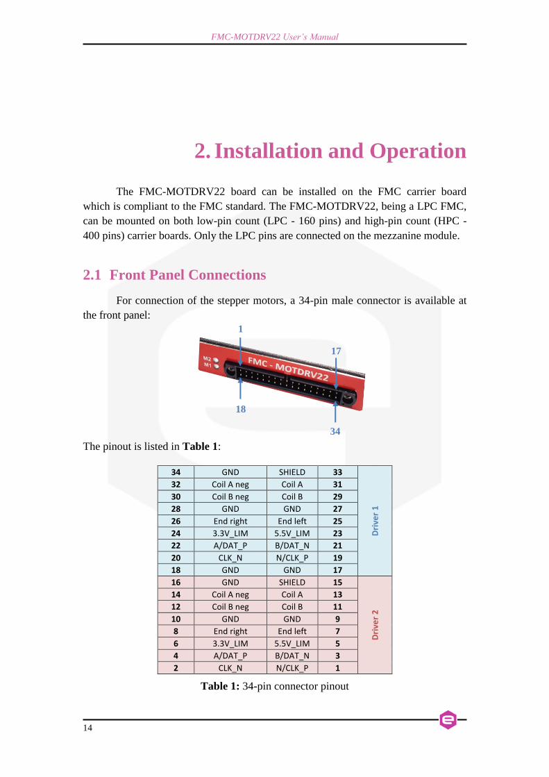
2.1 Front Panel Connections
For connection of the stepper motors, a 34-pin male connector is available at
the front panel:
The pinout is listed in Table 1:
34 GND SHIELD 33
Dri
ver
1
32 Coil A neg Coil A 31
30 Coil B neg Coil B 29
28 GND GND 27
26 End right End left 25
24 3.3V_LIM 5.5V_LIM 23
22 A/DAT_P B/DAT_N 21
20 CLK_N N/CLK_P 19
18 GND GND 17
16 GND SHIELD 15
Dri
ver
2
14 Coil A neg Coil A 13
12 Coil B neg Coil B 11
10 GND GND 9
8 End right End left 7
6 3.3V_LIM 5.5V_LIM 5
4 A/DAT_P B/DAT_N 3
2 CLK_N N/CLK_P 1
Table 1: 34-pin connector pinout
1
17
18
34

FMC-MOTDRV22 User’s Manual
15
2.2 Cable Connections
The FMC-MOTDRV22 can be provided with a proper cable (34-pin male
connector to 2 D-SUB HD 15 connectors). Three different cable lengths are available
(see description in the “Ordering Options” section):
Figure 7: FMC-MOTDRV22 and its cable
The pinout on the D-SUB HD 15 connectors is presented below (refer to Table 1):

FMC-MOTDRV22 User’s Manual
16
Figure 8: Cable Connections
2.3 On-Board Connectors
Hereafter the pin assignment on the LPC connector is listed:
C D G H
1 GND NC GND NC
2 NC GND NC PRSNT_M2C#
3 NC GND NC GND
4 GND NC GND NC
5 GND NC GND NC
6 NC GND Enable_MD2 GND
7 NC GND ALERT_MD2# Clock Motordriver 2
8 GND I2C_SDA_User GND SPI_CS_MD2#
9 GND I2C_SCL_User SPI_SCK_MD2 GND
10 Clock Motordriver 1 GND SPI_MOSI_MD2 SPI_MISO_MD2
11 SPI_MOSI_MD1 SPI_CS_MD1# GND Stallguard Motordriver 2
12 GND SPI_SCL_MD1 MUX_Encoder_Ch2 GND
13 GND GND Inc.-Encoder Ch2 B Inc.-Encoder Ch2 N
14 EnDat2.2 Ch1 Direction SPI_MISO_MD1 GND Inc.-Encoder Ch2 A
15 Stallguard Motordriver 1 EnDat2.2 Ch1 Data EnDat2.2 Ch2 Data GND
16 GND GND EnDat2.2 Ch2 Direction EnDat2.2 Ch2 Clock
17 GND SPI_MOSI_Controller GND ALERT_MD1#
18 SPI_MISO_Controller Interrupt Controller PosComp GND
19 Enable MD1 GND Clock Controller SPI_CS_CTRL#
20 GND MUX_Encoder_Ch1 GND SPI_SCL_CTRL
21 GND Inc.-Encoder Ch1 N LED Ch1_2 GND
22 Inc.-Encoder Ch1 A GND LED Ch1_1 Inc.-Encoder Ch1 B
23 EnDat2.2 Ch1 Clock #FAULT_LIM_M2 GND LED Ch2_2
24 GND EN_5V_LIM_M2 EN_3V3_LIM_M2 GND
25 GND GND EN_3V3_LIM_M1 LED Ch2_1
26 NC NC GND EN_5V_LIM_M1
27 NC NC NC GND
28 GND GND NC NC
29 GND NC GND #FAULT_LIM_M1
30 I2C_SCL_Managment TDI NC GND
31 I2C_SDA_Managment TDO NC NC
32 GND PWR_3.3V_Managment GND NC
33 GND NC NC GND
34 GA0 NC NC NC
35 PWR 12V GA1 GND NC
36 GND PWR 3.3V NC GND
37 PWR 12V GND NC NC
38 GND PWR 3.3V GND NC
39 PWR 3.3V GND NC GND
40 GND PWR 3.3V GND NC

FMC-MOTDRV22 User’s Manual
17
3. Ordering Options
The three main ordering codes for the FMC-MOTDRV22 are the following:
M O T D R V 2 2 I N 1 2
2-Channel Stepper Motor Driver with 12 V Internal Power
M O T D R V 2 2 E X 1 2
2-Channel Stepper Motor Driver with 12 V External Power
M O T D R V 2 2 E X 2 4
2-Channel Stepper Motor Driver with 24 V External Power
These units differ by the power supply that is fed to the FMC card: the
standard ordering code MOTDRV22IN12 receives the power directly from the +12 V
on the FMC connector while the MOTDRV22EX12 and the MOTDRV22EX24 from
an external 12 V or 24 V power source respectively.
3.1 Optional Codes
The FMC-MOTDRV22 boards can be provided with the corresponding cable.
Three different cables are available (with different lengths of 1 meter, 20 meters and
91 meters):
C A B L - F M T 0 0 0 1
Cable for FMC-MOTDRV 1m
Standard Code

FMC-MOTDRV22 User’s Manual
18
C A B L - F M T 0 0 0 2
Cable for FMC-MOTDRV 20m
C A B L - F M T 0 0 0 3
Cable for FMC-MOTDRV 91m
FMC-MOTDRV22 User’s Manual
19
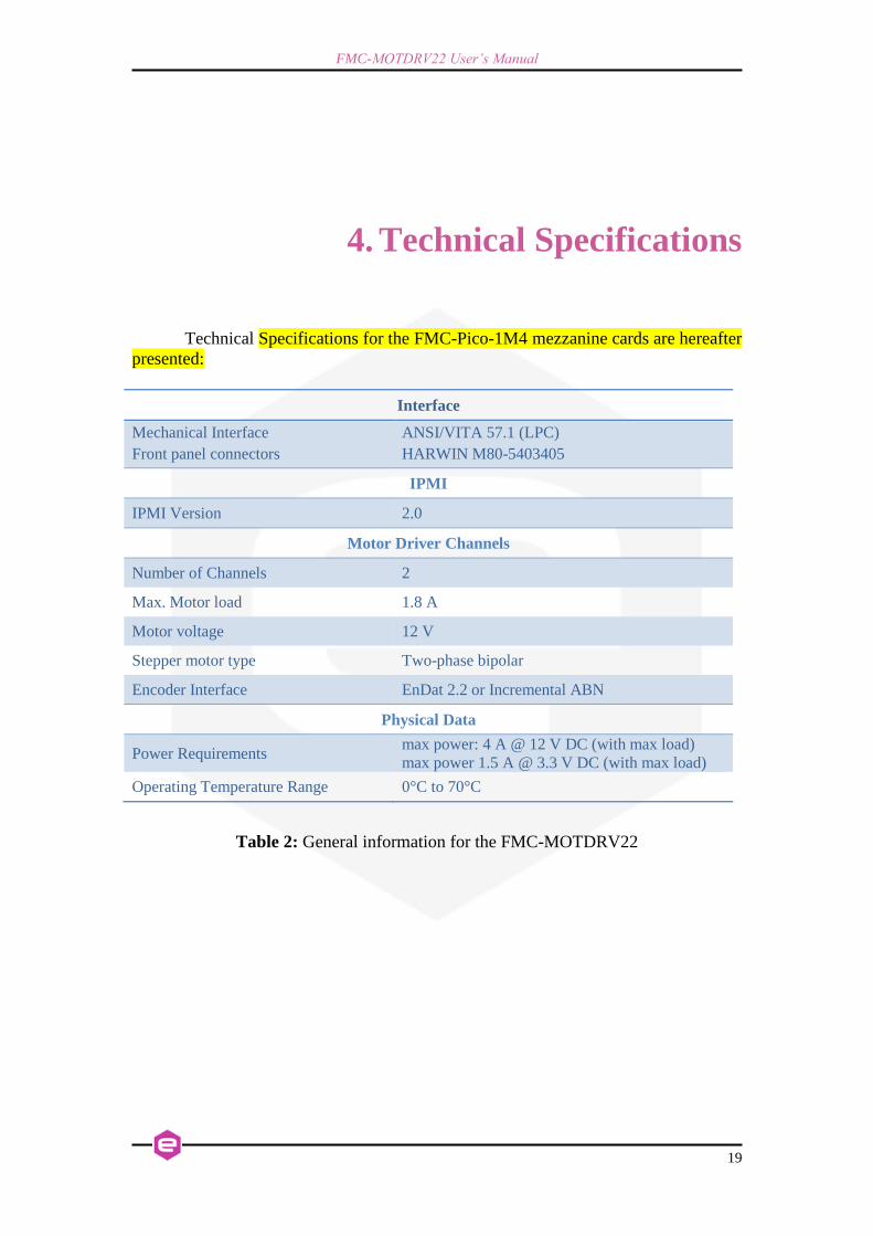
4. Technical Specifications
Technical Specifications for the FMC-Pico-1M4 mezzanine cards are hereafter
presented:
Interface
Mechanical Interface
Front panel connectors
ANSI/VITA 57.1 (LPC)
HARWIN M80-5403405
IPMI
IPMI Version 2.0
Motor Driver Channels
Number of Channels 2
Max. Motor load 1.8 A
Motor voltage 12 V
Stepper motor type Two-phase bipolar
Encoder Interface EnDat 2.2 or Incremental ABN
Physical Data
Power Requirements max power: 4 A @ 12 V DC (with max load)
max power 1.5 A @ 3.3 V DC (with max load)
Operating Temperature Range 0°C to 70°C
Table 2: General information for the FMC-MOTDRV22