fmq-20kwc/fmq-30kwc 20/30 kw fm …qei-rf.com/documentation/fmq-20kwc fm...
TRANSCRIPT

FMQ-20KWC/FMQ-30KWC 20/30 KW FM TRANSMITTER
INSTALLATION AND OPERATIONS MANUAL
DESIGNED AND MANUFACTURED BY
QEI CORPORATION P.O. BOX 805
WILLIAMSTOWN, NJ 08094 USA 856-728-2020
856-629-1751 (Fax) [email protected] (e-mail)
http://www.qei-broadcast.com

TABLE OF CONTENTS
Rev. 2/09 Page# TOC-1
Warranty Statement Page W-1 Section 1 General Information Page 1-1
1.1 Introduction Page 1-11.2 Cautions Page 1-11.3 Physical Description Page 1-21.4 Electrical Description Page 1-31.5 Specifications Page 1-31.6 Equipment Identification Page 1-4
Section 2 Installation Page 2-12.1 Initial Inspection Page 2-12.2 Environmental Requirements Page 2-12.3 Mechanical Requirements Page 2-22.4 Electrical Requirements Page 2-22.5 System Connections Page 2-3
Section 3 Operation Page 3-13.1 Controls and Indicators Page 3-13.2 Preparation For Initial Operation Page 3-33.3 Initial Turn On Procedure Page 3-43.4 Normal Operation Page 3-53.5 Remote Control Page 3-53.6 Factory Meter Readings Page 3-63.7 Fault Indicators Page 3-6
WARRANTY STATEMENT
Rev. 7/01 Page W-1
All equipment designed and manufactured by QEI Corporation is warranted against defects in workmanship and material that develop under normal use within a period of one (1) year from the date of original shipment subject to the following conditions and limitations: 1. The purchaser is not in default under his contract of purchase.
2. The sole responsibility of QEI Corporation for any equipment not conforming to this warranty shall be, at QEI’s option:
(a) To repair or replace such equipment or otherwise cause it to meet the represented specifications either at the purchaser’s installation or upon return thereof F.O.B. Williamstown, New Jersey, as directed by QEI Corporation; or
(b) To demonstrate that the equipment has no defect in workmanship or material and that it meets the represented specifications, in which event all expenses reasonably incurred by QEI Corporation in so demonstrating including but not limited to cost of travel to and from the purchaser's installation, and subsistence, shall be paid by purchaser to QEI Corporation.
3. In case of any equipment thought to be defective, the purchaser must, within seven (7) days notify QEI Corporation, in writing, giving full particulars as to the defects. Upon receipt of such notice, QEI Corporation will give instructions respecting the shipment of the equipment, or such other manner as it elects to service this warranty as above provided.
4. Equipment shall not be deemed to be defective if, after examination by QEI Corporation, the equipment evidences damage from moisture, temperature, lightning, improper handling, installation, operation, accident, or abuse.
5. Equipment, accessories, tubes, and batteries not manufactured by QEI Corporation are subject to only such adjustments as QEI Corporation my obtain from the supplier thereof.
6. This warranty extends only to the original purchaser and is not assignable or transferable.
7. QEI Corporation further guarantees that any radio transmitter described herein will deliver specified radio frequency power output at the antenna lead when connected to a suitable load, but such guarantee shall not be construed as a guarantee of any definite coverage or range of said apparatus.
8. NO OTHER WARRANTIES, EXPRESS OF IMPLIED INCLUDING ANY IMPLIED WARRANTY OF MERCHANTABILITY OR FITNESS FOR A PARTICULAR PURPOSE SHALL BE APPLICABLE TO ANY EQUIPMENT SOLD BY QEI CORPORATION, AND NO REPRESENTATIVE OR OTHER PERSON IS AUTHORIZED BY QEI CORPORATION TO ASSUME FOR IT ANY LIABILITY OR OBLIGATION WITH RESPECT TO THE CONDITION OR PERFORMANCE OF ANY EQUIPMENT SOLD BY IT, EXCEPT AS PROVIDED IN THIS WARRANTY. THIS WARRANTY PROVIDES FOR THE SOLE RIGHT AND REMEDY OF THE PURCHASE AND QEI CORPORATION SHALL IN NO EVENT HAVE ANY LIABILITY FOR CONSEQUENTIAL DAMAGES OR FOR LOSS, DAMAGE, OR EXPENSE DIRECTLY OR INDIRECTLY ARISING FROM THE USE OF THE EQUIPMENT PURCHASED FROM QEI CORPORATION.
SECTION 1 GENERAL INFORMATION
Rev. 2/09 Page 1-1
SECTION 1 GENERAL INFORMATION
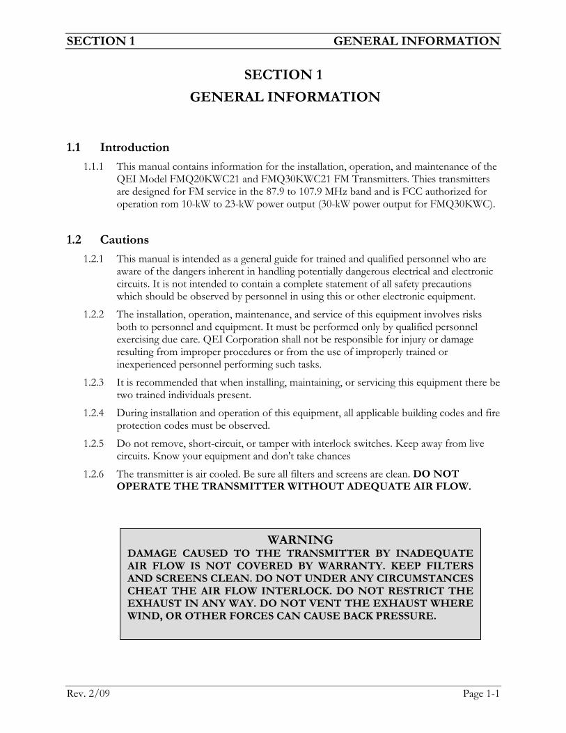
1.1 Introduction 1.1.1 This manual contains information for the installation, operation, and maintenance of the
QEI Model FMQ20KWC21 and FMQ30KWC21 FM Transmitters. Thies transmitters are designed for FM service in the 87.9 to 107.9 MHz band and is FCC authorized for operation rom 10-kW to 23-kW power output (30-kW power output for FMQ30KWC).
1.2 Cautions 1.2.1 This manual is intended as a general guide for trained and qualified personnel who are
aware of the dangers inherent in handling potentially dangerous electrical and electronic circuits. It is not intended to contain a complete statement of all safety precautions which should be observed by personnel in using this or other electronic equipment.
1.2.2 The installation, operation, maintenance, and service of this equipment involves risks both to personnel and equipment. It must be performed only by qualified personnel exercising due care. QEI Corporation shall not be responsible for injury or damage resulting from improper procedures or from the use of improperly trained or inexperienced personnel performing such tasks.
1.2.3 It is recommended that when installing, maintaining, or servicing this equipment there be two trained individuals present.
1.2.4 During installation and operation of this equipment, all applicable building codes and fire protection codes must be observed.
1.2.5 Do not remove, short-circuit, or tamper with interlock switches. Keep away from live circuits. Know your equipment and don't take chances
1.2.6 The transmitter is air cooled. Be sure all filters and screens are clean. DO NOT OPERATE THE TRANSMITTER WITHOUT ADEQUATE AIR FLOW.
WARNING DAMAGE CAUSED TO THE TRANSMITTER BY INADEQUATE AIR FLOW IS NOT COVERED BY WARRANTY. KEEP FILTERS AND SCREENS CLEAN. DO NOT UNDER ANY CIRCUMSTANCES CHEAT THE AIR FLOW INTERLOCK. DO NOT RESTRICT THE EXHAUST IN ANY WAY. DO NOT VENT THE EXHAUST WHERE WIND, OR OTHER FORCES CAN CAUSE BACK PRESSURE.

SECTION 1 GENERAL INFORMATION
Rev. 2/09 Page 1-2
1.2.7 The amplifier utilizes high voltage in PA. When working on the amplifier, be sure to remove all mains power and use the grounding stick to short all high voltage terminals. Never work on this equipment when alone or when fatigued.
1.2.8 It is recommended that communications (preferably a hardwire telephone) be near and operating when maintenance is being performed.
1.2.9 It is recommended that all personnel have basic first aid training including knowledge of cardiopulmanary resusatation (CPR), first aid for electrocution, first aid for shock, etc.
1.3 Physical Description 1.3.1 The amplifier is housed in two 24"W x 36"D x 76"H (61cm x 91cm x 193cm) steel
cabinets. The cabinet designations are as follows (Figure 1-1):
o Power Supply Cabinet – designated “PS”, this cabinet contains the mains power input connections, power distribution to the IPA, Filament, and PA Power supplies, relay controls, high voltage plate power supply, and remote control interface.
o Power Amplifier Cabinet – designated “PA”, this cabinet contains the IPA power supplies, IPA Assembly (APC/Splitter, IPA modules, Combiner), power amplifier input tuning, power amplifier, and RF output connection.
1.3.2 Primary AC power input is at the top of the ‘PS’ cabinet. RF output is at the top of the ‘PA’ cabinet. Cooling air is admitted through a replaceable filters located on the rear door of the cabinets and is exhausted at the top of the cabinets. The cabinets are pressurized by fans located inside the rear door. Pressurizing the cabinets in this manner minimizes dust and dirt infiltration. Remote control connections are located on the rear of the PSA2 Control & Meter Panel of the ‘PS’ cabinet.
1.3.3 The amplifier high voltage plate power supply transformer is located in the bottom of the ‘PS’ cabinet. High voltage rectifiers, capacitors, choke, current transducers, and
WARNING
THIS TRANSMITTER CONTAINS VOLTAGES THAT CAN KILL. ALWAYS DE-ENERGIZE THE TRANSMITTER BY SHUTTING THE POWER OFF AT THE WALL DISCONNECT AND SHORTING THE HIGH VOLTAGE CAPACITORS WITH THE GROUNDING STICK BEFORE ATTEMPTING ANY MAINTENANCE. IT IS SUGGESTED THAT THE GROUNDING STICK BE LEFT ACROSS THE HIGH VOLTAGE SUPPLY WHILE WORK IS BEING PERFORMED. DO NOT JUMPER ANY OF THE SAFETY INTERLOCK SWITCHES. IT IS ALSO RECOMMENDED THAT NO ONE PERSON PERFORM MAINTENANCE ON THE AMPLIFIER WITHOUT A SAFETY PERSON PRESENT.

SECTION 1 GENERAL INFORMATION
Rev. 2/09 Page 1-3
bleeder resistors are located in the rear of the ‘PS’ cabinet. The filament transformer is located in the bottom rear of the ‘PA’ cabinet.
1.3.4 The amplifier metering, control, fault, and indicator functions are located on the swing out PSA2 Control & Meter Panel Assembly on the front of the ‘PS’ cabinet.
1.3.5 The amplifier low voltage control power supplies, and relay control ladder are located behind the PSA2 Control & Meter Panel Assembly.
1.3.6 The PSA3 Breaker Panel Assembly contains the circuit breaker, fuses, high voltage power supply contactor, etc. and in located at the top front of the ‘PS’ cabinet.
1.3.7 The PAA1 is the chassis of the ‘PA’ cabinet. This contains the filament transformer, power amplifier blower, RF connections, output directional coupler, etc.
1.3.8 The PAA3 is the IPA Power Supply Assembly. This assembly contains 2 or 3 each 1500 Watt 48 VDC power supplies (one for each IPA module), IPA metering, and protective circuitry for the IPA.
1.3.9 The PAA4 is the IPA Assembly. This assembly contains the power control, driver amplifier and splitter, two or three IPA RF amplifier modules capable of about 600 Watts each, directional coupler for each IPA module, and a two or three way combiner.
1.3.10 The PAA5 is the Filament Metering and PA Output Tuning Assembly. This assembly contains filament metering and adjustment along with PA Output Tune and Load switches and Raise/Lower power switch.
1.3.11 The PAA6 is the Power Amplifier. This assembly contains the air cooled 3CX15,000A7 tube and associated circuitry.
1.4 Electrical Description 1.4.1 The amplifier requires a three phase power source of 208/240 VAC at 60 Hz . Power
line isolation transformer rectifier circuits are used to develop approximately 8500 VDC for the plate.
1.4.2 The RF section consists of an IPA assembly that will supply approximately 1000 to 1800 Watts (depending on model) to PA. The PA utilizes a 3CX15,000A7 in grounded grid configuration to supply the final 20-30 KW power output. All control functions are operated from a 24 VDC power supply for safety and convenience. Amplifier protection is accomplished through extensive fault circuitry. All fault conditions will either turn the transmitter high voltage off or reduce the RF output.
1.5 Specifications 1.5.1 General
Frequency Range ........................................................................................87.9 to 107.9 MHz Type of Emission .......................................................................................... 180F3 or 300F9 AM Noise..................................................................................................greater than -55 dBc Incidental AM ..........................................................................................greater than -50 dBc Power Output................................................................10-kW to 23-kW for FMQ-20KWC
SECTION 1 GENERAL INFORMATION
Rev. 2/09 Page 1-4
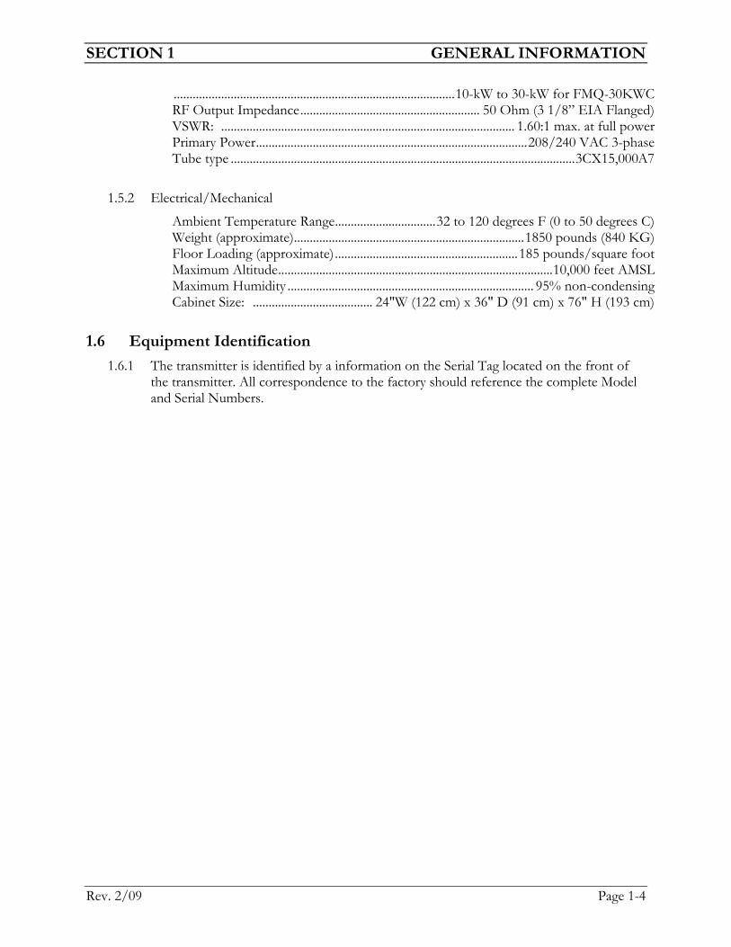
.........................................................................................10-kW to 30-kW for FMQ-30KWC RF Output Impedance......................................................... 50 Ohm (3 1/8” EIA Flanged) VSWR: ............................................................................................. 1.60:1 max. at full power Primary Power......................................................................................208/240 VAC 3-phase Tube type .............................................................................................................3CX15,000A7
1.5.2 Electrical/Mechanical
Ambient Temperature Range................................32 to 120 degrees F (0 to 50 degrees C) Weight (approximate).........................................................................1850 pounds (840 KG) Floor Loading (approximate)..........................................................185 pounds/square foot Maximum Altitude.......................................................................................10,000 feet AMSL Maximum Humidity .............................................................................. 95% non-condensing Cabinet Size: ...................................... 24"W (122 cm) x 36" D (91 cm) x 76" H (193 cm)
1.6 Equipment Identification 1.6.1 The transmitter is identified by a information on the Serial Tag located on the front of
the transmitter. All correspondence to the factory should reference the complete Model and Serial Numbers.
SECTION 2 INSTALLATION
Rev. 2/09 Page 2-1
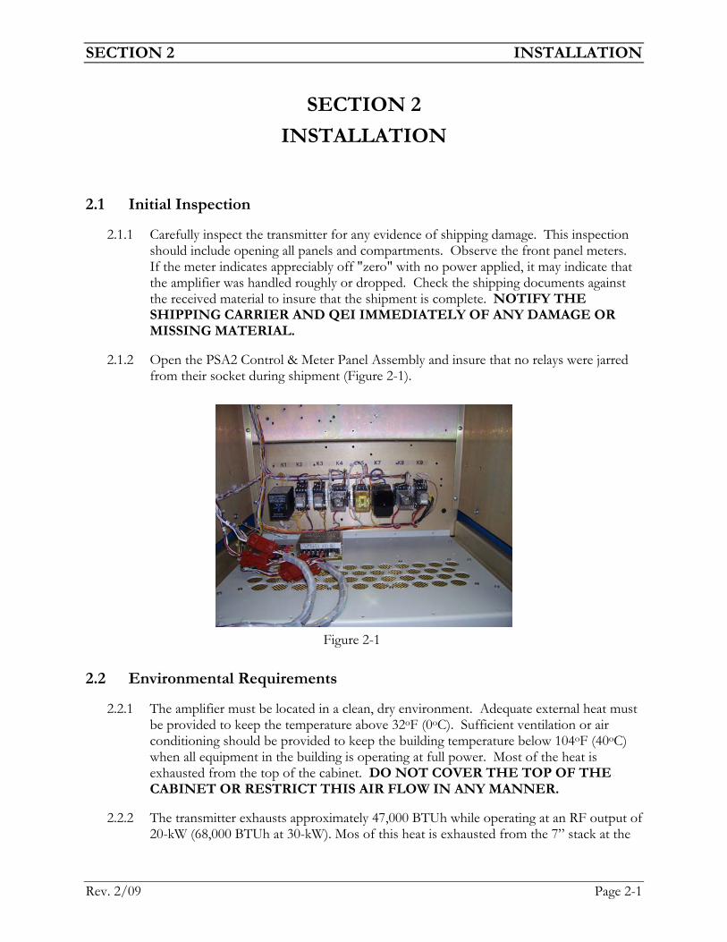
SECTION 2 INSTALLATION
2.1 Initial Inspection
2.1.1 Carefully inspect the transmitter for any evidence of shipping damage. This inspection should include opening all panels and compartments. Observe the front panel meters. If the meter indicates appreciably off "zero" with no power applied, it may indicate that the amplifier was handled roughly or dropped. Check the shipping documents against the received material to insure that the shipment is complete. NOTIFY THE SHIPPING CARRIER AND QEI IMMEDIATELY OF ANY DAMAGE OR MISSING MATERIAL.
2.1.2 Open the PSA2 Control & Meter Panel Assembly and insure that no relays were jarred from their socket during shipment (Figure 2-1).
2.2 Environmental Requirements
2.2.1 The amplifier must be located in a clean, dry environment. Adequate external heat must be provided to keep the temperature above 32oF (0oC). Sufficient ventilation or air conditioning should be provided to keep the building temperature below 104oF (40oC) when all equipment in the building is operating at full power. Most of the heat is exhausted from the top of the cabinet. DO NOT COVER THE TOP OF THE CABINET OR RESTRICT THIS AIR FLOW IN ANY MANNER.
2.2.2 The transmitter exhausts approximately 47,000 BTUh while operating at an RF output of 20-kW (68,000 BTUh at 30-kW). Mos of this heat is exhausted from the 7” stack at the
Figure 2-1
SECTION 2 INSTALLATION
Rev. 2/09 Page 2-2
top of the ‘PA’ cabinet. If this air is ducted out of the building, it may be necessary to provide an exhaust fan in the duct so as not to restrict the air flow through the PA tube. It will also be necessary to provide an air inlet to the building to “make up” for the air exhausted by the blower (approximately 1000 cfm).
2.3 Mechanical Requirements
2.3.1 The transmitter must be placed on a sturdy floor which can safely support the weight of the unit. At least 24 inches (60 cm) should be provided above the cabinet to avoid restricting air flow and allowing exhaust heat to dissapate. Adequate space should be provided on all sides of the transmitter for ease of access for service. A minimum of 36 inches (1 M) is suggested. Adequate lighting should be provided as well as sufficient grounded three-prong wall outlets for test equipment, soldering irons, etc.
2.4 Electrical Requirements
2.4.1 The transmitter requires a 208/240 VAC three phase 60 Hz main power supply capable of 150 amps (175 Amps for FMQ-30KWC). The power must be routed through a wall disconnect switch or circuit breaker which will remove all power from the transmitter when opened. THIS IS AN IMPORTANT SAFETY REQUIREMENT.
WARNING
DAMAGE CAUSED TO THE TRANSMITTER BY INADEQUATE AIR FLOW IS NOT COVERED BY WARRANTY. KEEP FILTERS AND SCREENS CLEAN. DO NOT UNDER ANY CIRCUMSTANCES CHEAT THE AIR FLOW INTERLOCKS. DO NOT RESTRICT THE EXHAUST IN ANY WAY. DO NOT VENT THE AIR EXHAUST WHERE WIND, OR OTHER FORCES CAN CAUSE BACK PRESSURE.
NOTE IT IS THE RESPONSIBILITY OF THE CUSTOMER TO CHECK AND ADHERE TO ALL LOCAL AND NATIONAL ELECTRICAL CODES REGULATING THE INSTALLATION OF THIS AMPLIFIER.
SECTION 2 INSTALLATION
Rev. 2/09 Page 2-3
2.5 System Connections
2.5.1 Intercabinet Connections
2.5.1.1 Connect the MS-type connector to the PA cabinet
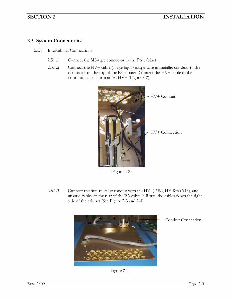
2.5.1.2 Connect the HV+ cable (single high voltage wire in metallic conduit) to the connector on the top of the PS cabinet. Connect the HV+ cable to the doorknob capacitor marked HV+ (Figure 2-2).
2.5.1.3 Connect the non-metallic conduit with the HV- (#19), HV Rtn (#13), and ground cables to the rear of the PA cabinet. Route the cables down the right side of the cabinet (See Figure 2-3 and 2-4).
Figure 2-2
HV+ Conduit HV+ Connection
Figure 2-3
Conduit Connection

SECTION 2 INSTALLATION
Rev. 2/09 Page 2-4
2.5.1.4 Route the black HV- (#19) and HV Rtn (#13) to the A1A Overload Assembly. Connect the cables to the circuit board as marked and be sure the cables are routed trough the cable holder to prevent the cables from touching the power resistors (Figure 2-5).
2.5.1.5 Route the green ground wire to the front of the PA cabinet. Remove the bottom front panel of the PA cabinet and connect the ground wire to the ground stud (Figure 2-6).
Figure 2-4
Figure 2-5
Cable Holder HV- (#19) HV Rtn (#13)
Figure 2-6

SECTION 2 INSTALLATION
Rev. 2/09 Page 2-5
2.5.1.5 Locate the two coaxial cables with BNC connectors labeled ‘F’ and ‘R’ on the top of the PS cabinet. Route these cables through the gromet hole on the PA cabinet (Figure 2-7).
2.5.1.6 Route these cables to the directional coupler. Connect the cable labeled ‘F’ to the Incident port and the cable labeled ‘R’ to the Reflected port (Figure 2-8).
2.5.2 Primary Power
2.5.2.1 Connect the transmitter to 208/240 VAC, 60 Hz, three phase mains power only. Phase rotation is critical because of the use of a line voltage monitor (A3K1).
2.5.2.2 OPEN THE MAIN DISCONNECT. VERIFY THAT THE MAINS POWER IS OFF.
2.5.2.3 Open the top front door of the PS cabinet.
Figure 2-7
Coaxial Cables ‘F’ & ‘R’
Figure 2-8
Reflected Port Incident Port

SECTION 2 INSTALLATION
Rev. 2/09 Page 2-6
2.5.2.4 Route the mains power cables through the supplied bushing in the top of the PS cabinet. Connect the main power wires to Mains Terminal Block PS-TB1. Connect a phase to each terminal and ground to the green ground terminal (Figure 2-9 & 2-10).
2.5.2.5 Measure the 208/240 volt line. Change the wires on the high voltage plate transformer in the ‘PS’ cabinet and the filament transformer in the ‘PA’ cabinet to the taps which most closely approximate the operating line voltage. Remember to change all taps (including jumpers on the high voltage transformer) if necessary. The high voltage transformer primary is wired in “delta”. Contact QEI Technical Support if you are not sure of this process.
Figure 2-9
Mains Power Bushing
Figure 2-10
Mains AC Input Ground
SECTION 2 INSTALLATION
Rev. 2/09 Page 2-7
Line Voltage Tap
198 208 and -10
208 208 and 0
218 208 and +10
230 240 and -10
240 240 and 0
250 240 and +10
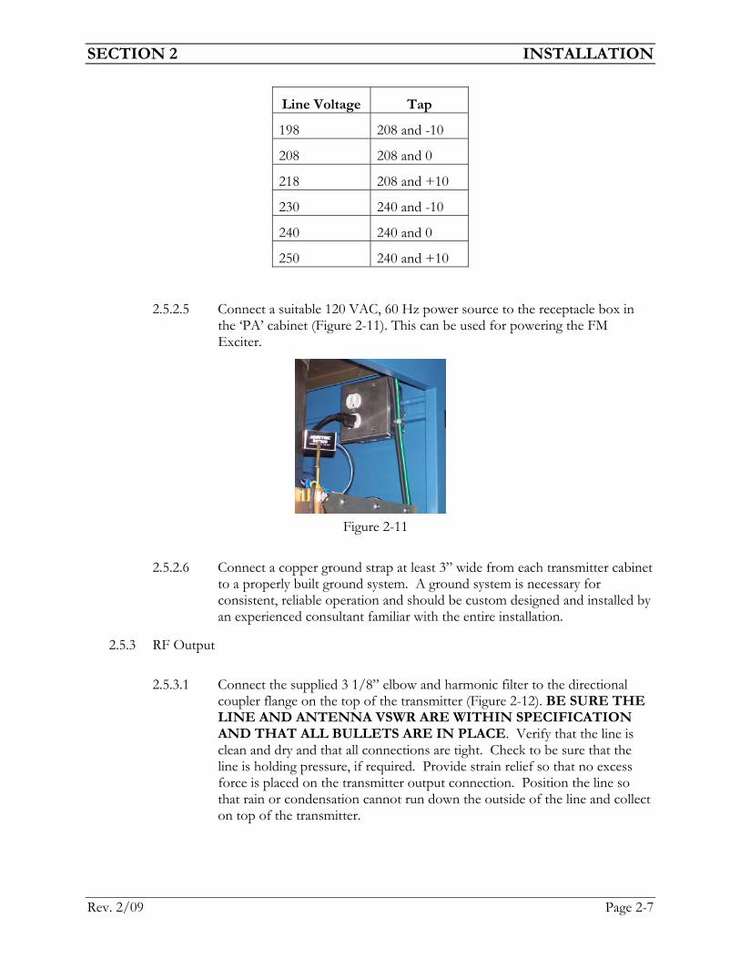
2.5.2.5 Connect a suitable 120 VAC, 60 Hz power source to the receptacle box in the ‘PA’ cabinet (Figure 2-11). This can be used for powering the FM Exciter.
2.5.2.6 Connect a copper ground strap at least 3” wide from each transmitter cabinet to a properly built ground system. A ground system is necessary for consistent, reliable operation and should be custom designed and installed by an experienced consultant familiar with the entire installation.
2.5.3 RF Output
2.5.3.1 Connect the supplied 3 1/8” elbow and harmonic filter to the directional coupler flange on the top of the transmitter (Figure 2-12). BE SURE THE LINE AND ANTENNA VSWR ARE WITHIN SPECIFICATION AND THAT ALL BULLETS ARE IN PLACE. Verify that the line is clean and dry and that all connections are tight. Check to be sure that the line is holding pressure, if required. Provide strain relief so that no excess force is placed on the transmitter output connection. Position the line so that rain or condensation cannot run down the outside of the line and collect on top of the transmitter.
Figure 2-11

SECTION 2 INSTALLATION
Rev. 2/09 Page 2-8
2.5.4 Audio (Composite Stereo) and SCA
2.5.4.1 Refer to the Exciter manual for appropriate information.
2.5.5 Remote Control Connection
2.5.5.1 Remote control wiring can pickup signals from other equipment in the building and cause erroneous operation of the amplifier. Always check your amplifier for proper operation before connecting the remote control. If pickup on the remote control wiring is suspected, RF by-passing of the remote control wiring will be necessary.
2.5.5.2 See Table 2.1 for connection descriptions. Route the remote control wires through the plastic conduit at the top of the PS cabinet into the rear of the PAA2 Control and Meter Panel Assembly (Figure 2-13). These are located on TB1 at the bottom of PSA2 Control and Meter Panel Assembly (Figure 2-14).
Figure 2-14
Remote Control Connections
Figure 2-12
RF Output
Figure 2-13

SECTION 2 INSTALLATION
Rev. 2/09 Page 2-9
Function Terminal Description
RF Forward 1 Trasnmitter RF Forward 0-10 VDC.
RF Reflected 2 Transmitter RF Reflected 0-10 VDC.
Plate Current 3 Plate Current Sample 0-10 VDC.
Plate Voltage 4 Plate Voltage Sample 0-10 VDC
Ground 5 Ground reference connection
Rem Lower 6 Normal Open. Close to ground to lower transmitter RF Output
Rem Raise 7 Normal Open. Close to ground to raise transmitter RF Output
Ground 8 Ground reference connection
Rem HV On 9 Normal Open. Momentary close to ground to turn high voltage on.
Rem HV Off 10 Normal Open. Momentary close to ground to turn high voltage off.
Rem Fil On 11 Normal Open. Momentary close to ground to turn filament on.
Rem Fil Off 12 Normal Open. Momentary close to ground to turn filament off.
Ground 13 Ground reference connection
Rem Reset 14 Normal Open. Momentary close to ground to reset faults
Spare 15-18 Not Used
Aux Intlk 19 Auxilary Interlock. Must be closed to #20 for transmitter to operate.
Aux Intlk 20 Auxilary Interlock. Must be closed to #19 for transmitter to operate.
Table 2.1

SECTION 3 OPERATION
Rev. 2/09 Page 3-1
SECTION 3 OPERATION
3.1 Controls and Indicators 3.1.1 Meter Panel PSA2 Assembly (See Figure 3-1)
3.1.1.1 Plate Voltage – Indicates the voltage applied to the Plate (Anode) of the PA tube.
3.1.1.2 Plate Current – Indicates the Plate current of the PA tube.
3.1.1.3 Grid Current – Indicates the grid current of the PA tube.
3.1.1.4 Forward Power – Indicates forward power (in kilowatts) output of the RF Amplifier.
3.1.1.5 Reflected Power – Indicates reflected power (in Watts) output og the RF Amplifier.
3.1.1.6 Faults -- LEDs which indicate the following when illuminated.
Plate Overload ..........................Indicates a plate overload has occurred. Grid Overload............................ Indicates a grid overload has occurred. VSWR............................................ Indicates a VSWR fault has occurred.
Reset .............................................................Used to reset fault condition.

SECTION 3 OPERATION
Rev. 2/09 Page 3-2
3.1.1.7 Status -- LEDs which indicate the following when illuminated.
PS Front OK............................... Indicates PS Front interlock is closed. PS Rear OK................................... Indicates PS Rear interlock is closed.
PA Rear OK..................................Indicates PA Rear interlock is closed. PA Stk OK ................................ Indicates PA Ground stick is in holder. PS Stk OK ................................... Indicates PS ground stick is in holder. Aux OK ................................................ Indicates Aux interlock is closed.
3.1.1.8 Off Switch -- used to turn the filament voltage, blowers/fans, etc. off. Switch is active in either local or remote control.
3.1.1.9 Filament On Switch -- used to turn the blowers/fans and filament voltage on when in local control.
3.1.1.10 Local/Remote Switch -- used to switch amplifier between local and remote control.
3.1.1.11 HV Off Switch -- used to turn the high voltage (plate voltage) off. Switch is active in either local or remote control.
3.1.1.12 HV On Switch -- used to turn the high voltage (plate voltage) on when in local control.
3.1.2 Breaker Panel PSA3 Assembly (See Figure 3-2)
3.1.2.1 IPA Fuses – 10 Amp fuses for the IPA power supplies.
Figure 3-2

SECTION 3 OPERATION
Rev. 2/09 Page 3-3
3.1.2.2 FANS/BLOWER FUSES – 15 Amp fuses for the fans and blowers.
3.1.2.3 CONTROL FUSES – 1 Amp fuses for the phase fault relay and control (+24 VDC) power supply.
3.1.2.4 FILAMENT FUSES – 10 Amp fuses for the tube filament power supply.
3.1.2.5 MAIN BREAKER – 150 Amp circuit breaker for high voltage (plate) power supply.
3.13 IPA Power Supply (Figure 3-3)
3.1.3.1 The IPA Power Supply will consist of 2 or 3 power supplies and metering depending on the model of the transmitter purchased.
3.1.3.2 IPA Metering
Amps – Indicates total current supply to IPA module. Volts – Indicates voltage on IPA module. Rev – Indicates Reflected Power on IPA module. Fwd – Indicates Forward Power on IPA module.
3.2 Preparation For Initial Operation 3.2.1 Confirm that primary power is disconnected from the amplifier.
3.2.2 Installation Checkout
WARNING THIS AMPLIFIER USES VOLTAGES THAT CAN KILL. DO NOT ATTEMPT ANY ADJUSTMENTS OR MAINTENANCE WITHOUT FIRST REMOVING PRIMARY POWER. USE THE GROUNDING STICK TO DISCHARGE THE HIGH VOLTAGE FILTER CAPACITORS EVERY TIME YOU ENTER THE AMPLIFIER. IT IS RECOMMENDED THAT GROUNDING STICK BE LEFT ACROSS THE HIGH VOLTAGE SUPPLY WHEN EVER WORK IS BEING PERFORMED
Figure 3-3

SECTION 3 OPERATION
Rev. 2/09 Page 3-4
3.2.2.1 Recheck the electrical and mechanical details for conformance to the requirements set out in Section 2.
3.2.2.2 Recheck that electrical connections are properly made and tight.
3.2.2.3 Recheck that all transformer taps are set properly.
3.2.2.4 Check that the PA tube is firmly seated in its socket.
3.2.2.5 Check that all access panels and doors are closed and that covers removed for inspection are in place.
3.2.2.6 Insure that the transmission line and load is properly connected.
3.2.2.7 Insure that a remote control is connected to the transmitter.
3.2.2.8 Insure that the AUX interlock is shorted.
3.3 Initial Turn On Procedure 3.3.1 Place the following switches and controls in the indicated position:
LOCAL/REMOTE switch...................................................................................... LOCAL MAIN Circuit Breaker (A3CB1) .....................................................................................ON
Exciter RF Output...................................................................................................Minimum
3.3.2 Apply Primary power to the amplifier. The PS GND STK and PA GND STK Status lights should be on. If not, the ground sticks are not secure in their holder. The Red ‘OFF’ switch will light. If the light is not on, an interlock is open or there is a phase error on the incoming AC power. This is usually due to a phase rotation error. Remove all power from the transmitter and swap two of the incoming AC power lines. When all phases are correct, the LED on the phase monitor relay will light.
3.3.3 Depress the FILAMENT ON switch. All Interlock Status lights should be green. The fans and PA blower will start and the green ‘FILAMENT ON’ light will be on.
3.3.4 Remove the air filter on the rear of the PA cabinet and observe the direction of rotation of the blower impeller wheel. The rotation must be counterclockwise (CCW). If the direction of rotation in incorrect (clockwise) turn the transmitter off. Remove all primary power from the transmitter (Open wall disconnects). Reverse any two phases either at the wall disconnect or the transmitter. Insure all connections are proper and tight and reapply primary power to the transmitter. Proceed from 3.3.1.
3.3.4 Use the Filament Voltage Meter to verify that the PA Filament Voltage is 6.3 Volts. Use the Filament Adjust control if necessary.
3.3.5 The PA filament requires a warm up time of approximately 30 seconds. After this time has elapsed, the red light in the HV OFF switch will turn on.
3.3.6 Depress the HV ON switch.
3.3.7 Verify that the PLATE VOLTS meter reads approximately 9000 Volts and the PLATE CURRENT meter reads approximately 1.0 Amps.
SECTION 3 OPERATION
Rev. 2/09 Page 3-5
3.3.8 Verify that the IPA Voltage meter reads approximately 48 Volts on each IPA power supply.
3.3.9 Hold the RF Output switch in the Raise position for about 30 Seconds.
3.3.10 Using the data sheet supplied with the transmitter, slowly increase the RF Output of the exciter while watching the Forward Power Meter, Plate Current Meter, Reflected Power Meter, and IPA Metering. NOTE: DO NOT EXCEED 18 AMPS ON ANY IPA MODULE OR 5.0 AMPS PLATE CURRENT. RF output of the transmitter should increase as the exciter power output is increased. Use the PA Output Tune and Load controls as required to peak the indication on the RF Forward Meter. Do not exceed rated power output of the transmitter. If the Reflected Power Meter should begin to rise rapidly, STOP. Turn the transmitter off and check all RF connections between the output of the transmitter and the antenna.
3.3.11 Determine the DC Plate Power Input to the PA required to provide the licensed transmitter power output (TPO) for the station by dividing the TPO by the efficiency factor. The efficiency factor is determined from information supplied with the transmitter.
3.3.12 Adjust the exciter output until the product of the Plate Voltage time the Plate Current equals the DC Plate Power Input required.
3.3.13 Use the PA Output Tune and Load controls as required to peak the indication on the Forward Power Meter. NOTE: TUNE/LOAD SETTINGS MUST BE ADJUSTED TO THEIR FINAL SETTINGS AT THE NORMAL OPERATING RF POWER OF THE TRANSMITTER.
3.4 Normal Operation 3.4.1 Keep a regular log of the various meter readings to assist in maintenance and
troubleshooting.
3.4.2 Occasionally check the PA Filament Voltage and PA Output tuning to insure optimum operation.
3.4.3 Since the PA tube 3CX15,000A7 has a thoriated tungsten filament, it is recommended that the filament be shut off whenever the transmitter is to be off for more than 15 minutes. This type of filament is gradually losing emission as long as it is hot regardless of whether high voltage is applied. Follow manufacturers recommendations for maximum tube life.
3.4.4 Check air filter and replace as necessary.
3.5 Remote Control 3.5.1 Place the LOCAL/REMOTE switch in the REMOTE position.
3.5.2 Use the Remote Control functions as outlined in Table 2.1 as required to control the transmitter.

SECTION 3 OPERATION
Rev. 2/09 Page 3-6
3.6 Factory Meter Readings 3.6.1 The factory tested meter readings supplied were taken with the transmitter operating
at full power output or the TPO (if supplied) into a 50 Ohm load. A variance of up to 15% can be expected.
3.7 Fault Indicators 3.7.1 The following table will list the transmitter faults, the trip points, and action taken. If
a fault should occur, depressing the ‘Reset’ switch either local or remote will reset the fault.
Fault Trip Point Action
OUTPUT VSWR >2100 Watts Reflected Low Power
GRID FAULT 1.5 A Plate Off
PLATE FAULT 6.0 A Plate Off