fmr linewidths of yig films fabricated by ex situ post-annealing of amorphous films deposited by rf...
TRANSCRIPT

phys. stat. sol. (a) 204, No. 3, 763–767 (2007) / DOI 10.1002/pssa.200622412
© 2007 WILEY-VCH Verlag GmbH & Co. KGaA, Weinheim
Original
Paper
FMR linewidths of YIG films
fabricated by ex situ post-annealing of amorphous films
deposited by rf magnetron sputtering
Young-Min Kang, Alexander N. Ulyanov, and Sang-Im Yoo*
Department of Materials Science and Engineering, Seoul National University, San 56-1, Shilim-dong,
Kwanak-ku, Seoul 151-744, Korea
Received 18 August 2006, revised 28 October 2006, accepted 3 November 2006
Published online 19 December 2006
PACS 75.50.Gg, 76.50.+g, 81.15.Cd
FMR linewidths of Y3Fe
5O
12 (YIG) films fabricated by ex situ post-annealing of amorphous films depos-
ited by radio frequency magnetron sputtering are reported. Amorphous YIG films were deposited on both
thermally oxidized Si(100) and Gd3Ga
5O
12 (GGG) (111) substrates and subsequently crystallized by ex
situ post-annealing (600–900 °C) in two different oxygen atmospheres (air and 500 ppm O2). The compo-
sitions of as-deposited films were very sensitive to the oxygen partial pressure (PO2
) of the sputtering gas.
During the post-annealing process, crystalline YIG phase started to grow upward on the substrates. High-
quality YIG films showing narrow FMR linewidths (∆H) of 5.3 and 70 Oe for GGG and thermally oxi-
dized Si substrates, respectively, could be grown from the amorphous films deposited in pure Ar gas,
composed of the cation ratio (Y:Fe = 3.04:4.96) close to the stoichiometric YIG. A reduced oxygen an-
nealing atmosphere was found more effective than air for obtaining narrower FMR linewidths.
© 2007 WILEY-VCH Verlag GmbH & Co. KGaA, Weinheim
1 Introduction
Garnet films have been fabricated by various techniques, including liquid-phase epitaxy (LPE), pulsed
laser deposition (PLD), radio frequency (rf) magnetron sputtering, chemical vapor deposition, etc. [1].
Among these techniques, LPE is the most well-established method for fabrication of films for microwave
devices because high-quality thick films are obtainable more easily compared to other methods [1, 2].
High-quality Y3Fe5O12 (YIG) thin films have been prepared using the in situ on-chip PLD method for
magneto-optic devices [1, 3–5]. The FMR linewidths of LPE-grown YIG films were found to be ~1 Oe
and their saturation magnetizations were reported to have values close to that of bulk YIG. Those values
for epitaxial YIG films grown by PLD are also close to those of LPE-grown YIG [1–5].
The sputtering method has also been used for the preparation of rare earth garnet films for applications
in bubble-domain or magneto-optical devices. However, in applications for microwave devices, it has the
disadvantages of slow deposition rate and difficulties in controlling the composition of multi-component
oxides like YIG [1, 7–10]. To overcome the difficulty in obtaining stoichiometric YIG films by in situ
sputtering, we employed the following two-step approach in the study reported here. The first step is to
obtain amorphous films having a composition close to stoichiometric YIG by rf magnetron sputtering at
room temperature. Optimal deposition conditions could be obtained by analyzing the compositions of
amorphous films sputtered in various atmospheres. The next step is to produce YIG films through the
crystallization of optimally sputtered amorphous films. The ex situ post-annealing was performed in air
* Corresponding author: e-mail: [email protected], Phone: +82 2 880 5720, Fax: +82 2 885 9671
764 Y.-M. Kang et al.: FMR linewidths of YIG films
© 2007 WILEY-VCH Verlag GmbH & Co. KGaA, Weinheim www.pss-a.com
and also in a reduced oxygen atmosphere of 500 ppm O2 for this purpose. In this paper, we report the
FMR linewidth dependence on the composition of YIG films and crystallization conditions, which is
very critical to achieve optimal processing conditions of YIG films.
2 Experimental
Amorphous YIG films were deposited on both thermally oxidized Si(100) and Gd3Ga5O12 (GGG) (111)
single-crystal substrates by rf magnetron sputtering at room temperature. YIG target with a 2-inch di-
ameter was prepared by a solid-state reaction using precursors of Y2O3 and Fe2O3 powders of 99.9%
purity. For rf sputtering, the base pressure in the vacuum chamber was maintained at 3 × 10⁻⁶ Torr. To
find the optimal processing atmosphere for obtaining amorphous films of a composition close to the
stoichiometric YIG, various mixed gases with the oxygen ratios, R (= O2/(Ar + O2) × 100%) = 0, 1.0, 5.0,
and 10% were examined. For each sputtering gas, deposition of amorphous films on both thermally oxi-
dized Si (YIG/SiO2) and GGG substrates (YIG/GGG) was performed at room temperature for 2 h. The rf
power was maintained at 100 W, the gas flow rate was 16 SCCM (cubic centimeters per minute at stan-
dard temperature and pressure), and the target-to-substrate distance was 6 cm. To grow YIG films, as-
sputtered amorphous films were annealed at temperatures in the range 600–900 °C in air and reduced
oxygen atmosphere of 500 ppm O2.
Inductively coupled plasma–Auger electron spectroscopy (ICP-AES; ICPS-1000IV, Shimadzu)
analysis was carried out to investigate the compositions of as-deposited amorphous films. Microstructure
was analyzed using scanning electron microscopy (SEM; JSM6330F, JEOL) and also transmission elec-
tron microscopy (TEM; JEM 3000F, JEOL). A vibrating sample magnetometer (SHAKES, TBL 9600)
was used to measure the magnetization of the films. FMR measurements were carried out using an elec-
tron spin resonance (ESR) spectrometer (JES-TE300) with field parallel to the film plane. The first de-
rivative of power absorption spectra was measured.
3 Results and discussion
SEM cross-section views and AES-ICP analysis of as-deposited amorphous YIG films were used to
define the deposition rate and compositions of as-deposited amorphous YIG films. The compositions and
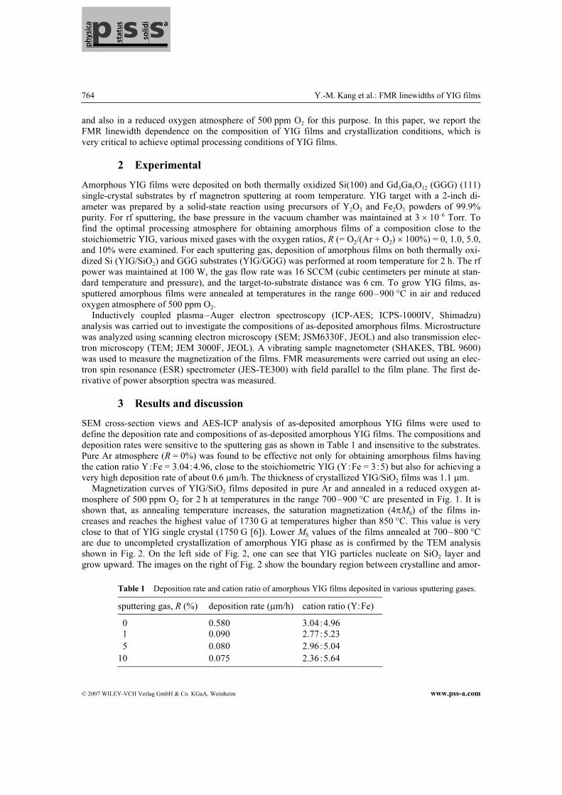
deposition rates were sensitive to the sputtering gas as shown in Table 1 and insensitive to the substrates.
Pure Ar atmosphere (R = 0%) was found to be effective not only for obtaining amorphous films having
the cation ratio Y:Fe = 3.04:4.96, close to the stoichiometric YIG (Y:Fe = 3:5) but also for achieving a
very high deposition rate of about 0.6 µm/h. The thickness of crystallized YIG/SiO2 films was 1.1 µm.
Magnetization curves of YIG/SiO2 films deposited in pure Ar and annealed in a reduced oxygen at-
mosphere of 500 ppm O2 for 2 h at temperatures in the range 700–900 °C are presented in Fig. 1. It is
shown that, as annealing temperature increases, the saturation magnetization (4πMS) of the films in-
creases and reaches the highest value of 1730 G at temperatures higher than 850 °C. This value is very
close to that of YIG single crystal (1750 G [6]). Lower MS values of the films annealed at 700–800 °C
are due to uncompleted crystallization of amorphous YIG phase as is confirmed by the TEM analysis
shown in Fig. 2. On the left side of Fig. 2, one can see that YIG particles nucleate on SiO2 layer and
grow upward. The images on the right of Fig. 2 show the boundary region between crystalline and amor-
Table 1 Deposition rate and cation ratio of amorphous YIG films deposited in various sputtering gases.
sputtering gas, R (%) deposition rate (µm/h) cation ratio (Y:Fe)
0 0.580 3.04:4.96
1 0.090 2.77:5.23
5 0.080 2.96:5.04
10 0.075 2.36:5.64

phys. stat. sol. (a) 204, No. 3 (2007) 765
www.pss-a.com © 2007 WILEY-VCH Verlag GmbH & Co. KGaA, Weinheim
Original
Paper
phous phase. The square boxes (a) and (b) are the upper and lower parts of the YIG growth front, respec-
tively. Fast Fourier transformation (FFT) patterns show that (a) and (b) parts of the film are in amor-
phous and crystalline states, respectively. In our previous report [11], we reported that crystalline YIG
started to grow at annealing temperatures higher than 680 °C on the amorphous SiO2 layer and 600 °C on
the GGG substrate when it was annealed in 500 ppm O2, implying that YIG growth kinetics was sensi-
tive to the substrate, annealing atmosphere, and temperature.
FMR spectra of YIG films deposited on SiO2 substrates are presented in Fig. 3. The films were depos-
ited in processing gas of R = 0 and 1.0% at room temperature and annealed in 500 ppm O2 atmosphere at
temperatures of 800, 850 and 900 °C. One can see that close to stoichiometry (Y:Fe = 3.04:4.96)
YIG films deposited with pure Ar gas (R = 0) show almost one resonance line with FMR peak-to-peak
Fig. 1 Magnetization curve of YIG/SiO2 annealed
for 2 h in 500 ppm O2 at temperatures in the range
700–900 °C.
Fig. 2 TEM cross-sectional images of YIG/SiO2 films
annealed at 700 °C for 2 h. A full cross-section image
(left) and a high-resolution image around the YIG growth
front (right) are presented. The square boxes (a) and (b)
marked in the image are the upper and lower parts of the
YIG growth front, respectively.
Fig. 3 FMR spectra and linewidth (∆H) of YIG/SiO2
films deposited with (a) R = 0% and (b) R = 1% sput-
tering gas. The films were annealed for 2 h in 500 ppm
O2 at temperatures of 800, 850 and 900 °C.
Fig. 4 FMR spectra of YIG/SiO2 films deposited with
R = 0% sputtering gas and annealed at 900 °C for 2 h
in 500 ppm O2 and air.

766 Y.-M. Kang et al.: FMR linewidths of YIG films
© 2007 WILEY-VCH Verlag GmbH & Co. KGaA, Weinheim www.pss-a.com
linewidth of around 75 Oe (Fig. 3, curve (a). A relatively broad FMR line obtained for polycrystalline
YIG films is caused by overlapping of resonance spectra for the grains with randomly oriented magnetic
easy axis. The YIG films, deposited with processing gas of R = 1%, have the off-stoichiometric cation
ratio of Y:Fe = 2.77:5.23, and show complex FMR spectra with the resonance occurring in the wide-
field range (see Fig. 3, curve (b). The complex and broad resonance spectra of the off-stoichiometric YIG
films are attributed to the second-phase effect on the FMR spectra. When Fe is in excess in the YIG
system, the second phase of Fe2O3 is supposed to exist in the YIG film [12], which can make the FMR
spectra broader and complex.
FMR spectra of YIG/SiO2 films deposited with R = 0% sputtering gas and annealed at 900 °C for 2 h
in 500 ppm O2 and air are presented in Fig. 4. FMR linewidth (=70 Oe) of the films annealed in 500 ppm
O2 is lower than that of the air-annealed one (138 Oe). Thus, we can conclude that a reduced oxygen
annealing atmosphere is more effective than air for fabricating high-quality YIG films.
Figure 5 shows FMR spectra of YIG/GGG films deposited with R = 0 and 1.0% sputtering gas and
annealed in reduced oxygen atmosphere at different temperatures. FMR spectra of the films were much
sharper in comparison with those of the YIG/SiO2 films. The reason is that the GGG (111) substrate
strongly induces highly textured YIG crystals during the post-annealing process. The YIG/GGG films, as
well as the YIG/SiO2 ones, show sharper FMR spectra if deposited at R = 0% than those of films depos-
ited at R = 1.0%. The FMR linewidth values of the YIG/GGG films are presented in Table 2. From the
FMR linewidth point of view, the optimum annealing temperature for YIG/GGG films is 850 °C: the
narrowest FMR spectra with linewidth values of 5.3 and 5.8 Oe are obtained from the samples deposited
in sputtering gases of R = 0 and 1.0%, respectively.
4 Conclusions
We successfully fabricated YIG films on thermally oxidized Si(100) and GGG (111) substrates by two-
step processing–deposition of amorphous YIG films by sputtering at room temperature and subsequent
Table 2 FMR linewidths of YIG/GGG films deposited with R = 0 and 1% sputtering gas. The films
were annealed for 2 h in 500 ppm O2 at various temperatures.
FMR linewidth (Oe) annealing temperature
(°C) R = 0% R = 1%
800 8.8 16.1
850 5.3 5.8
900 5.8 12.4
Fig. 5 FMR spectra of YIG/GGG deposited with (a)
R = 0% and (b) R = 1% sputtering gas. The films were
annealed for 2 h in 500 ppm O2 at temperatures of 800, 850
and 900 °C.

phys. stat. sol. (a) 204, No. 3 (2007) 767
www.pss-a.com © 2007 WILEY-VCH Verlag GmbH & Co. KGaA, Weinheim
Original
Paper
crystallization of those films by post-annealing. Amorphous YIG films with compositions close to
stoichiometry (Y:Fe = 3:5) were obtained when deposited in pure Ar. A reduced oxygen annealing
atmosphere is more effective than air from the viewpoint of FMR linewidth values. The films deposited
on GGG substrates show much smaller FMR linewidths than those of films deposited on thermally oxi-
dized Si substrates.
Acknowledgement This work was supported in part by the Korean Science and Engineering Foundation through
the Research Center for Advanced Magnetic Materials at Chung-nam National University.
References
[1] D. B. Chrisey, P. C. Dorsey, J. D. Adam, and H. Buhay, Handbook of Thin Film Devices, Vol. 4: Microwave
Magnetic Film Devices (Academic Press, New York, 2000).
[2] C. Vittoria, P. Lubitz, P. Hansen, and W. Tolksdorf, J. Appl. Phys. 57, 3699 (1985).
[3] P. C. Dorsey, S. E. Bushnell, R. G. Seed, and C. Vittoria, J. Appl. Phys. 74, 1242 (1993).
[4] S. Kahl and A. M. Grishin, J. Appl. Phys. 93, 6945 (2003).
[5] E. Popova, N. Keller, F. Gendron, M. Guyot, M. C. Brianso, Y. Dumond, and M. Tessier, J. Appl. Phys. 90,
1422 (2001).
[6] W. H. Vonlock, Handbook of Microwave Ferrite Materials (Academic Press, New York, 1965), p. 78.
[7] J. J. Cuomo, V. Sadagopan, J. DeLuca, P. Chaudhari, and R. Rosenberg, Appl. Phys. Lett. 21, 15 (1972).
[8] M. Gomi, H. Furuyama, and M. Abe, J. Appl. Phys. 70, 7065 (1991).
[9] E. Sawatzky and E. Kay, J. Appl. Phys. 39, 4700 (1968).
[10] M.-B. Park and N.-H. Cho, J. Magn. Magn. Mater. 231, 253 (2001).
[11] Y.-M. Kang, S.-H. Wee, S.-I. Baik, S.-G. Min, S.-C. Yu, S.-H. Moon, Y.-W. Kim, and S.-I. Yoo, J. Appl. Phys.
97, 10A319-1 (2005).
[12] J. Cassedanne, C.R. Acad. Sci. 252, 3262 (1961).