fnio ethernet/ip adapter na-9188 fnio s-series
TRANSCRIPT

1 FnIO EtherNET/IP Adapter NA-9188 FnIO S-Series
Copyright(C) CREVIS Co.,Ltd Support +82-31-273-6453 URL : www.crevis.co.kr
Version 1.02
2012 CREVIS Co.,Ltd
NA-9188
User Manual
EtherNET/IP Adapter
2 FnIO EtherNET/IP Adapter NA-9188 FnIO S-Series
Copyright(C) CREVIS Co.,Ltd Support +82-31-273-6453 URL : www.crevis.co.kr
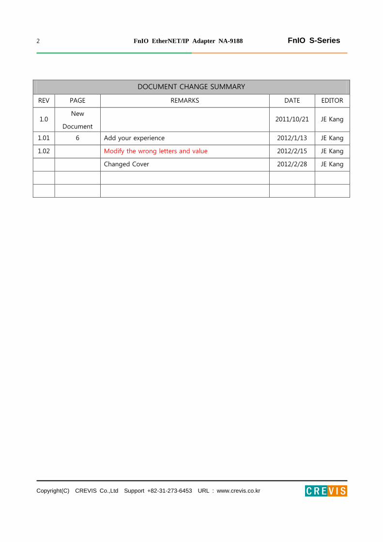
DOCUMENT CHANGE SUMMARY
REV PAGE REMARKS DATE EDITOR
1.0 New
Document 2011/10/21 JE Kang
1.01 6 Add your experience 2012/1/13 JE Kang
1.02 Modify the wrong letters and value 2012/2/15 JE Kang
Changed Cover 2012/2/28 JE Kang

3 FnIO EtherNET/IP Adapter NA-9188 FnIO S-Series
Copyright(C) CREVIS Co.,Ltd Support +82-31-273-6453 URL : www.crevis.co.kr
CONTENTS
1. Important Notes ......................................................................................................................................................... 6
1.1. Safety Instruction ...................................................................................................................................... 7
1.1.1. Symbols ......................................................................................................................................................... 7
1.1.2. Safety Notes ................................................................................................................................................ 7
1.1.3. Certification ................................................................................................................................................. 7
2. Specification .................................................................................................................................................................. 8
2.1. The Interface ............................................................................................................................................... 8
2.1.1. NA-9188 (EtherNET/IP) ........................................................................................................................... 8
2.2. Specification ................................................................................................................................................ 9
2.2.1. General Specification ............................................................................................................................... 9
2.2.2. Interface Specification........................................................................................................................... 10
2.3. LED Indicator ............................................................................................................................................. 11
2.3.1. Module Status LED (MOD) ................................................................................................................. 11
2.3.2. Network Status LED (NET) .................................................................................................................. 11
2.3.3. Link/Active Status LED(LINK) ............................................................................................................. 11
2.3.4. Expansion Module Status LED (I/O) ............................................................................................... 12
2.3.5. Field Power Status LED ........................................................................................................................ 12
3. Dimension .................................................................................................................................................................... 13
3.1. NA-9188 ...................................................................................................................................................... 13
4. Mechanical Setup ..................................................................................................................................................... 14
4.1. Total Expansion ........................................................................................................................................ 14
4.2. Plugging and Removal of the Components. .............................................................................. 14
4.3. Internal FnBus/Field Power Contacts ............................................................................................. 15
5. EHERNET/IP Electrical Interface .......................................................................................................................... 16
5.1. FnBus System ............................................................................................................................................ 16
FnBus Pin Description ............................................................................................................................................ 17
5.2. ETHERNET/IP Electrical Interface ...................................................................................................... 18

4 FnIO EtherNET/IP Adapter NA-9188 FnIO S-Series
Copyright(C) CREVIS Co.,Ltd Support +82-31-273-6453 URL : www.crevis.co.kr
5.2.1. NA-9188 ...................................................................................................................................................... 18
5.2.2. EtherNET/IP IP Address Setup........................................................................................................... 18
5.2.3. I/O Process Image Map ....................................................................................................................... 21
5.3. Example ....................................................................................................................................................... 22
5.3.1. Example of Input Process Image(Input Register) Map .......................................................... 22
5.3.2. Example of Output Process Image(Output Register) Map .................................................. 25
6. OBJECT MODELS ...................................................................................................................................................... 26
6.1. Supported Objects ................................................................................................................................. 26
6.2. Identity Object ......................................................................................................................................... 27
6.2.1. Common Services ................................................................................................................................... 27
6.2.2. Class Attributes ........................................................................................................................................ 27
6.2.3. Instance Attributes ................................................................................................................................. 28
6.3. Message Router Object ....................................................................................................................... 29
6.3.1. Common Services ................................................................................................................................... 29
6.3.2. Class Attributes ........................................................................................................................................ 29
6.3.3. Instance Attributes ................................................................................................................................. 29
6.4. Assembly Object...................................................................................................................................... 30
6.4.1. Common Services ................................................................................................................................... 30
6.4.2. Class Attributes ........................................................................................................................................ 30
6.4.3. Instance Attributes ................................................................................................................................. 30
6.5. Connection Manager Object ............................................................................................................. 31
6.5.1. Class Attributes, Instance Attribute ................................................................................................ 31
6.6. Port Object ................................................................................................................................................. 32
6.6.1. Common Services ................................................................................................................................... 32
6.6.2. Class Attributes ........................................................................................................................................ 32
6.6.3. Instance Attributes ................................................................................................................................. 32
6.7. TCP/IP Object ........................................................................................................................................... 33
6.7.1. Common Services ................................................................................................................................... 33

5 FnIO EtherNET/IP Adapter NA-9188 FnIO S-Series
Copyright(C) CREVIS Co.,Ltd Support +82-31-273-6453 URL : www.crevis.co.kr
6.7.2. Class Attributes ........................................................................................................................................ 33
6.7.3. Instance Attributes ................................................................................................................................. 33
6.8. EtherNET/IP Object ................................................................................................................................ 34
6.8.1. Common Services ................................................................................................................................... 34
6.8.2. Class Attributes ........................................................................................................................................ 34
6.8.3. Instance Attributes ................................................................................................................................. 34
6.9. FnBus Manager Object ......................................................................................................................... 35
6.9.1. Common Services ................................................................................................................................... 35
6.9.2. Class Attributes ........................................................................................................................................ 35
6.9.3. Instance Attributes ................................................................................................................................. 35
6.10. Expansion Slot Object ........................................................................................................................... 39
6.10.1. Common Services ................................................................................................................................... 39
6.10.2. Class Attributes ........................................................................................................................................ 39
6.10.3. Instance Attributes ................................................................................................................................. 39
6.11. EtherNET/IP Reference .......................................................................................................................... 43
7. Trouble Shooting ...................................................................................................................................................... 44
7.1. How to diagnose by LED indicator ................................................................................................. 44
7.2. How to diagnose when device couldn’t communicate network ....................................... 45
APPENDIX A ......................................................................................................................................................................... 46
A.1. Product List............................................................................................................................................................. 46
A.2. Glossary .................................................................................................................................................................... 48

6 FnIO EtherNET/IP Adapter NA-9188 FnIO S-Series
Copyright(C) CREVIS Co.,Ltd Support +82-31-273-6453 URL : www.crevis.co.kr
1. Important Notes
Solid state equipment has operational characteristics differing from those of electromechanical equipment.
Safety Guidelines for the Application, Installation and Maintenance of Solid State Controls describes some important
differences between solid state equipment and hard-wired electromechanical devices.
Because of this difference, and also because of the wide variety of uses for solid state equipment, all persons
responsible for applying this equipment must satisfy themselves that each intended application of this equipment is
acceptable.
In no event will CREVIS be responsible or liable for indirect or consequential damages resulting from the use or
application of this equipment.
The examples and diagrams in this manual are included solely for illustrative purposes. Because of the many variables
and requirements associated with any particular installation, CREVIS cannot assume responsibility or liability for actual
use based on the examples and diagrams.
If you don’t follow the directions, it could cause a personal injury, damage to the equipment or explosion
Do not assemble the products and wire with power applied to the system. Else it may cause an electric arc, which
can result into unexpected and potentially dangerous action by field devices. Arching is explosion risk in
hazardous locations. Be sure that the area is non-hazardous or remove system power appropriately before
assembling or wiring the modules.
Do not touch any terminal blocks or IO modules when system is running. Else it may cause the unit to an electric
shock or malfunction.
Keep away from the strange metallic materials not related to the unit and wiring works should be controlled by the
electric expert engineer. Else it may cause the unit to a fire, electric shock or malfunction.
If you disobey the instructions, there may be possibility of personal injury, damage to equipment or
explosion. Please follow below Instructions.
Check the rated voltage and terminal array before wiring. Avoid the circumstances over 50℃ of temperature.
Avoid placing it directly in the sunlight.
Avoid the place under circumstances over 85% of humidity.
Do not place Modules near by the inflammable material. Else it may cause a fire.
Do not permit any vibration approaching it directly.
Go through module specification carefully, ensure inputs, output connections are made with the specifications. Use
standard cables for wiring.
Use Product under pollution degree 2 environment.
Warning!
Caution!

7 FnIO EtherNET/IP Adapter NA-9188 FnIO S-Series
Copyright(C) CREVIS Co.,Ltd Support +82-31-273-6453 URL : www.crevis.co.kr
1.1. Safety Instruction
1.1.1. Symbols
Identifies information about practices or circumstances that can cause an
explosion in a hazardous environment, which may lead to personal injury or
death property damage or economic loss.
Identifies information that is critical for successful application and understanding of the
Product.
Identifies information about practices or circumstances that can lead to personal
injury, property damage, or economic loss.
Attentions help you to identity a hazard, avoid a hazard, and recognize the consequences.
1.1.2. Safety Notes
The modules are equipped with electronic components that may be destroyed by electrostatic
discharge. When handling the modules, ensure that the environment (persons, workplace and
packing) is well grounded. Avoid touching conductive components, e.g. FnBUS Pin.
1.1.3. Certification
c-UL-us UL Listed Industrial Control Equipment, certified for U.S. and Canada
See UL File E235505
CE Certificate
EN 61000-6-2; Industrial Immunity
EN 61000-6-4; Industrial Emissions

8 FnIO EtherNET/IP Adapter NA-9188 FnIO S-Series
Copyright(C) CREVIS Co.,Ltd Support +82-31-273-6453 URL : www.crevis.co.kr
2. Specification
2.1. The Interface
2.1.1. NA-9188 (Ethernet/IP)

9 FnIO EtherNET/IP Adapter NA-9188 FnIO S-Series
Copyright(C) CREVIS Co.,Ltd Support +82-31-273-6453 URL : www.crevis.co.kr
2.2. Specification
2.2.1. General Specification
General Specification
System Power
Supply voltage : 24Vdc nominal
Supply voltage range : 11~28.8Vdc
Protection : Output current limit (Min. 1.5A)
Reverse polarity protection
Power Dissipation 60mA typical @24Vdc
Current for I/O Module 1.5A @5Vdc
Isolation System power to internal logic : Non-isolation
System power to I/O driver : Isolation
Field Power Supply voltage : 24Vdc nominal
Supply voltage range : 11~28.8Vdc
Max. Current Field Power
Contact DC 10A Max.
Weight 150g
Module Size 45mm x 99mm x 70mm
Environment Condition Refer to Environment Specification
Environmental Specifications
Operating Temperature -20 to 50℃
Non-Operating Temperature -40℃ to 85℃
Relative Humidity 5%~90% non-condensing
Operating Altitude 2000m
Mounting DIN rail

10 FnIO EtherNET/IP Adapter NA-9188 FnIO S-Series
Copyright(C) CREVIS Co.,Ltd Support +82-31-273-6453 URL : www.crevis.co.kr
2.2.2. Interface Specification
Interface Specification, NA-9188 (Ethernet/IP Adapter)
Adapter Type Level 2 I/O Server (Explicit, I/O Message)
Max. Expansion Module 32 slots
Max. Input Size 252bytes
Max. Output Size 252bytes
Max. Length Bus Line Up to 100m from Ethernet Hub/Switch with twisted CAT 3 UTP/STP
Max. Nodes Limited by Ethernet Specification
Max. Connection
16 IO message connections
64 CIP connections
64 Explicit message connections
Baud rate 10/100Mbps, Auto-negotiation, Full duplex
Protocol Ethernet/IP, BOOTP
Interface Connector RJ-45 socket
IP Address Setup Via BOOTP
Indicator
5 LEDs
1 Green/Red, Module Status (MOD)
1 Green, Network Status (NET)
1 Green, Link/Active Status (LINK)
1 Green/Red Expansion I/O Module Status (I/O)
1 Green, Field Power Status
Module Location Starter module left side of FnIO system
Field Power Detection About 11Vdc
11 FnIO EtherNET/IP Adapter NA-9188 FnIO S-Series
Copyright(C) CREVIS Co.,Ltd Support +82-31-273-6453 URL : www.crevis.co.kr
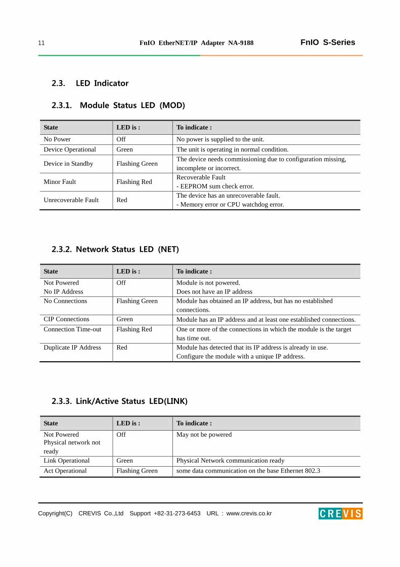
2.3. LED Indicator
2.3.1. Module Status LED (MOD)
State LED is : To indicate :
No Power Off No power is supplied to the unit.
Device Operational Green The unit is operating in normal condition.
Device in Standby Flashing Green The device needs commissioning due to configuration missing,
incomplete or incorrect.
Minor Fault Flashing Red Recoverable Fault
- EEPROM sum check error.
Unrecoverable Fault Red The device has an unrecoverable fault.
- Memory error or CPU watchdog error.
2.3.2. Network Status LED (NET)
State LED is : To indicate :
Not Powered
No IP Address
Off Module is not powered.
Does not have an IP address
No Connections Flashing Green Module has obtained an IP address, but has no established
connections.
CIP Connections Green Module has an IP address and at least one established connections.
Connection Time-out Flashing Red One or more of the connections in which the module is the target
has time out.
Duplicate IP Address Red Module has detected that its IP address is already in use.
Configure the module with a unique IP address.
2.3.3. Link/Active Status LED(LINK)
State LED is : To indicate :
Not Powered
Physical network not
ready
Off May not be powered
Link Operational Green Physical Network communication ready
Act Operational Flashing Green some data communication on the base Ethernet 802.3

12 FnIO EtherNET/IP Adapter NA-9188 FnIO S-Series
Copyright(C) CREVIS Co.,Ltd Support +82-31-273-6453 URL : www.crevis.co.kr
2.3.4. Expansion Module Status LED (I/O)
2.3.5. Field Power Status LED
State LED is : To indicate :
Not Powered
No Expansion Module Off Device has no expansion module or may not be powered
FnBus On-line,
Do not Exchanging I/O Flashing Green
FnBus is normal but does not exchanging I/O data
(Passed the expansion module configuration).
FnBus Connection,
Run Exchanging IO Green Exchanging I/O data
FnBus connection fault
during exchanging IO Red
One or more expansion module occurred in fault state.
- Changed expansion module configuration.
- FnBus communication failure.
Expansion
Configuration Failed Flashing Red
Failed to initialize expansion module
- Detected invalid expansion module ID.
- Overflowed Input / Output Size
- Too many expansion module
- Initial protocol failure
- Mismatch vendor code between adapter and expansion module.
State LED is : To indicate :
Not Supplied Field
Power Off Not supplied 24V dc field power
Supplied Field Power Green Supplied 24V dc field power

13 FnIO EtherNET/IP Adapter NA-9188 FnIO S-Series
Copyright(C) CREVIS Co.,Ltd Support +82-31-273-6453 URL : www.crevis.co.kr
3. Dimension
3.1. NA-9188
(mm)

14 FnIO EtherNET/IP Adapter NA-9188 FnIO S-Series
Copyright(C) CREVIS Co.,Ltd Support +82-31-273-6453 URL : www.crevis.co.kr
4. Mechanical Setup
4.1. Total Expansion
The number of the module assembly that can be connected is 32. So the maximum length is 426mm Exception.
ST-2748 is excepted to calculate maximum length because that is double width module.
4.2. Plugging and Removal of the Components.
Before work is done on the components, the voltage supply must be turned
off.
As above figure in order to safeguard the FnIO module from jamming, it should be fixed onto the DIN rail with
locking level. To do so, fold on the upper of the locking lever.
To pull out the FnIO module, unfold the locking lever as below figure.

15 FnIO EtherNET/IP Adapter NA-9188 FnIO S-Series
Copyright(C) CREVIS Co.,Ltd Support +82-31-273-6453 URL : www.crevis.co.kr
4.3. Internal FnBus/Field Power Contacts
Communication between the NA series and the expansion module as well as system / field power supply of the bus
modules is carried out via the internal bus. It is comprised of 6 data pin and 2 field power pin.
Do not touch data and field power pins in order to avoid soiling and damage
by ESD noise.

16 FnIO EtherNET/IP Adapter NA-9188 FnIO S-Series
Copyright(C) CREVIS Co.,Ltd Support +82-31-273-6453 URL : www.crevis.co.kr
5. EHERNET/IP Electrical Interface
5.1. FnBus System
• Network Adapter Module
The Network Adapter Module forms the link between the field bus and the field devices with the Expansion
Modules.
The connection to different field bus systems can be established by each of the corresponding Network Adapter
Module, e.g. for SyncNet, PROFIBUS, CANopen, DeviceNet, Ethernet/IP, CC-Link, MODBUS/Serial,
MODBUS/TCP etc.
17 FnIO EtherNET/IP Adapter NA-9188 FnIO S-Series
Copyright(C) CREVIS Co.,Ltd Support +82-31-273-6453 URL : www.crevis.co.kr
• Expansion Module
The Expansion Modules are supported a variety of input and output field devices.
There are digital and analog input/output modules and special function modules.
• Two types of FnBus Message
- Service Messaging
- I/O Messaging
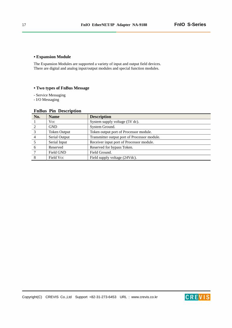
FnBus Pin Description
No. Name Description
1 Vcc System supply voltage (5V dc).
2 GND System Ground.
3 Token Output Token output port of Processor module.
4 Serial Output Transmitter output port of Processor module.
5 Serial Input Receiver input port of Processor module.
6 Reserved Reserved for bypass Token.
7 Field GND Field Ground.
8 Field Vcc Field supply voltage (24Vdc).

18 FnIO EtherNET/IP Adapter NA-9188 FnIO S-Series
Copyright(C) CREVIS Co.,Ltd Support +82-31-273-6453 URL : www.crevis.co.kr
5.2. ETHERNET/IP Electrical Interface
5.2.1. NA-9188
Shielded RJ-45 Socket
Ethernet/IP Network Setup is like following.
The use of an incorrect supply voltage or frequency can cause severe damage
to the component.
5.2.2.
RJ-45 Signal
Name Description
1 TD+ Transmit +
2 TD- Transmit -
3 RD+ Receive +
4 -
5 -
6 RD- Receive -
7 -
8 -
Case Shield
19 FnIO EtherNET/IP Adapter NA-9188 FnIO S-Series
Copyright(C) CREVIS Co.,Ltd Support +82-31-273-6453 URL : www.crevis.co.kr
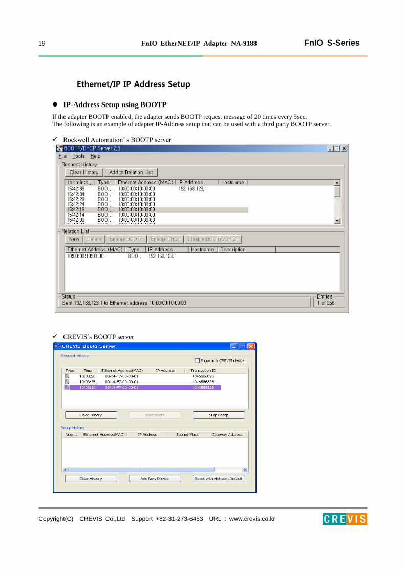
Ethernet/IP IP Address Setup
IP-Address Setup using BOOTP
If the adapter BOOTP enabled, the adapter sends BOOTP request message of 20 times every 5sec.
The following is an example of adapter IP-Address setup that can be used with a third party BOOTP server.
Rockwell Automation’ s BOOTP server
CREVIS’s BOOTP server

20 FnIO EtherNET/IP Adapter NA-9188 FnIO S-Series
Copyright(C) CREVIS Co.,Ltd Support +82-31-273-6453 URL : www.crevis.co.kr
21 FnIO EtherNET/IP Adapter NA-9188 FnIO S-Series
Copyright(C) CREVIS Co.,Ltd Support +82-31-273-6453 URL : www.crevis.co.kr
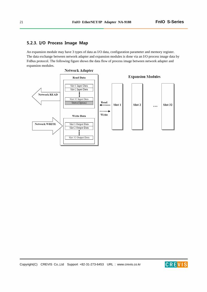
5.2.3. I/O Process Image Map
An expansion module may have 3 types of data as I/O data, configuration parameter and memory register.
The data exchange between network adapter and expansion modules is done via an I/O process image data by
FnBus protocol. The following figure shows the data flow of process image between network adapter and
expansion modules.

22 FnIO EtherNET/IP Adapter NA-9188 FnIO S-Series
Copyright(C) CREVIS Co.,Ltd Support +82-31-273-6453 URL : www.crevis.co.kr
5.3. Example
5.3.1. Example of Input Process Image(Input Register) Map
Input image data depends on slot position and expansion slot data type. Input process image data is only ordered
by expansion slot position when input image mode is uncompressed (mode 0, 2). But, when input image mode is
compressed (mode 1, 3), input process image data is ordered by expansion slot position and slot data type.
Input process image mode can be set by FnBus Manager Object attribute#5. Refer to 6.9.
For example slot configuration
Input Process Image Mode#0 (Status(2 bytes) + Uncompressed Input Processing Data)
Byte Bit 7 Bit 6 Bit 5 Bit 4 Bit 3 Bit 2 Bit 1 Bit 0
0 Field Power FnBus Status
1 Always 0, TBD
2 Empty, Always 0 Discrete Input 4 pts. (Slot#1)
3 Discrete Input 8 pts. (Slot#2)
4 Analog Input Ch0 low byte (Slot#3)
5 Analog Input Ch0 high byte (Slot#3)
6 Analog Input Ch1 low byte (Slot#3)
7 Analog Input Ch1 high byte (Slot#3)
8 Discrete Input low 8 pts. (Slot#4)
9 Discrete Input high 8 pts. (Slot#4)
10 Empty, Always 0 Discrete Input 4 pts. (Slot#5)
11 Discrete Input 8 pts. (Slot#6)
12 Empty, Always 0 Discrete Input 4 pts. (Slot#7)
13 Analog Input Ch0 low byte (Slot#8)
14 Analog Input Ch0 high byte (Slot#8)
15 Analog Input Ch1 low byte (Slot#8)
16 Analog Input Ch1 high byte (Slot#8)
17 Discrete Input low 8 pts. (Slot#9)
18 Discrete Input high 8 pts. (Slot#9)
19 Empty, Always 0 Discrete Input 4 pts. (Slot#10)
Slot Address Module Description
#0 Ethernet/IP Adapter
#1 4-discrete input
#2 8-discrete input
#3 2-analog input
#4 16-discrete input
#5 4-discrete input
#6 8-discrete input
#7 4-discrete input
#8 2-analog input
#9 16-discrete input
#10 4-discrete input
Status (2 bytes)

23 FnIO EtherNET/IP Adapter NA-9188 FnIO S-Series
Copyright(C) CREVIS Co.,Ltd Support +82-31-273-6453 URL : www.crevis.co.kr
FP (Field Power) :
0: 24Vdc Field Power On. 1: 24Vdc Field Power Off
FnBus Status :
0: Normal Operation 1: FnBus Standby
2: FnBus Communication Fault 3: Slot Configuration Failed
4: No Expansion Slot
Input Process Image Mode#1 (Status(2 bytes) + Compressed Input Processing Data)
Byte Bit 7 Bit 6 Bit 5 Bit 4 Bit 3 Bit 2 Bit 1 Bit 0
0 Field Power FnBus Status
1 Always 0, TBD
2 Analog Input Ch0 low byte (Slot#3)
3 Analog Input Ch0 high byte (Slot#3)
4 Analog Input Ch1 low byte (Slot#3)
5 Analog Input Ch1 high byte (Slot#3)
6 Analog Input Ch0 low byte (Slot#8)
7 Analog Input Ch0 high byte (Slot#8)
8 Analog Input Ch1 low byte (Slot#8)
9 Analog Input Ch1 high byte (Slot#8)
10 Discrete Input 8 pts. (Slot#2)
11 Discrete Input low 8 pts. (Slot#4)
12 Discrete Input high 8 pts. (Slot#4)
13 Discrete Input 8 pts. (Slot#6)
14 Discrete Input low 8 pts. (Slot#9)
15 Discrete Input high 8 pts. (Slot#9)
16 Discrete Input 4 pts. (Slot#5) Discrete Input 4 pts. (Slot#1)
17 Discrete Input 4 pts. (Slot#10) Discrete Input 4 pts. (Slot#7)
Input Assembly Priority :
1) Analog Input Data (Word type)
2) 8 or 16 points Discrete Input Data (Byte type)
3) 4 points Input Data (Bit type)
4) 2 points Input Data (Bit type)
*Enable Input Run/Idle Header’ and ‘Enable Output Run/Idle Header’ must be Disabled. Should do so is Image
mode. (Refer to 6.9)
Status
(1word)
24 FnIO EtherNET/IP Adapter NA-9188 FnIO S-Series
Copyright(C) CREVIS Co.,Ltd Support +82-31-273-6453 URL : www.crevis.co.kr
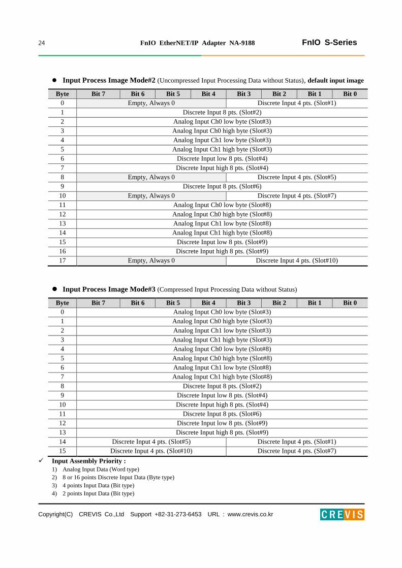
Input Process Image Mode#2 (Uncompressed Input Processing Data without Status), default input image
Byte Bit 7 Bit 6 Bit 5 Bit 4 Bit 3 Bit 2 Bit 1 Bit 0
0 Empty, Always 0 Discrete Input 4 pts. (Slot#1)
1 Discrete Input 8 pts. (Slot#2)
2 Analog Input Ch0 low byte (Slot#3)
3 Analog Input Ch0 high byte (Slot#3)
4 Analog Input Ch1 low byte (Slot#3)
5 Analog Input Ch1 high byte (Slot#3)
6 Discrete Input low 8 pts. (Slot#4)
7 Discrete Input high 8 pts. (Slot#4)
8 Empty, Always 0 Discrete Input 4 pts. (Slot#5)
9 Discrete Input 8 pts. (Slot#6)
10 Empty, Always 0 Discrete Input 4 pts. (Slot#7)
11 Analog Input Ch0 low byte (Slot#8)
12 Analog Input Ch0 high byte (Slot#8)
13 Analog Input Ch1 low byte (Slot#8)
14 Analog Input Ch1 high byte (Slot#8)
15 Discrete Input low 8 pts. (Slot#9)
16 Discrete Input high 8 pts. (Slot#9)
17 Empty, Always 0 Discrete Input 4 pts. (Slot#10)
Input Process Image Mode#3 (Compressed Input Processing Data without Status)
Byte Bit 7 Bit 6 Bit 5 Bit 4 Bit 3 Bit 2 Bit 1 Bit 0
0 Analog Input Ch0 low byte (Slot#3)
1 Analog Input Ch0 high byte (Slot#3)
2 Analog Input Ch1 low byte (Slot#3)
3 Analog Input Ch1 high byte (Slot#3)
4 Analog Input Ch0 low byte (Slot#8)
5 Analog Input Ch0 high byte (Slot#8)
6 Analog Input Ch1 low byte (Slot#8)
7 Analog Input Ch1 high byte (Slot#8)
8 Discrete Input 8 pts. (Slot#2)
9 Discrete Input low 8 pts. (Slot#4)
10 Discrete Input high 8 pts. (Slot#4)
11 Discrete Input 8 pts. (Slot#6)
12 Discrete Input low 8 pts. (Slot#9)
13 Discrete Input high 8 pts. (Slot#9)
14 Discrete Input 4 pts. (Slot#5) Discrete Input 4 pts. (Slot#1)
15 Discrete Input 4 pts. (Slot#10) Discrete Input 4 pts. (Slot#7)
Input Assembly Priority :
1) Analog Input Data (Word type)
2) 8 or 16 points Discrete Input Data (Byte type)
3) 4 points Input Data (Bit type)
4) 2 points Input Data (Bit type)

25 FnIO EtherNET/IP Adapter NA-9188 FnIO S-Series
Copyright(C) CREVIS Co.,Ltd Support +82-31-273-6453 URL : www.crevis.co.kr
5.3.2. Example of Output Process Image(Output Register) Map
Output image data depends on slot position and expansion slot data type. Output process image data is only
ordered by expansion slot position when output image mode is uncompressed (mode 0). But, when output image
mode is compressed (mode 1), output process image data is ordered by expansion slot position and slot data type.
Output process image mode can be set by FnBus Manager Object attribute#6. Refer to 6.9.
For example slot configuration
Output Process Image Mode#0 (Uncompressed Output Processing Data), default output image
Byte Bit 7 Bit 6 Bit 5 Bit 4 Bit 3 Bit 2 Bit 1 Bit 0
0 Empty, Don’t care Discrete Output 4 pts. (Slot#1)
1 Discrete Output 8 pts. (Slot#2)
2 Analog Output Ch0 low byte (Slot#3)
3 Analog Output Ch0 high byte (Slot#3)
4 Analog Output Ch1 low byte (Slot#3)
5 Analog Output Ch1 high byte (Slot#3)
6 Discrete Output low 8 pts. (Slot#4)
7 Discrete Output high 8 pts. (Slot#4)
8 Empty, Don’t care Discrete Output 4 pts. (Slot#5)
9 Discrete Output 8 pts. (Slot#6)
10 Empty, Don’t care Discrete Output 2 pts.
(Slot#7)
11 Empty, Don’t care Discrete Output 2 pts.
(Slot#8)
12 Analog Output Ch0 low byte (Slot#9)
13 Analog Output Ch0 high byte (Slot#9)
14 Analog Output Ch1 low byte (Slot#9)
15 Analog Output Ch1 high byte (Slot#9)
16 Discrete Output low 8 pts. (Slot#10)
17 Discrete Output high 8 pts. (Slot#10)
18 Empty, Don’t care Discrete Output 4 pts. (Slot#11)
Slot Address Module Description
#0 Ethernet/IP Adapter
#1 4-discrete output
#2 8-discrete output
#3 2-analog output
#4 16-discrete output
#5 4-discrete output
#6 8-discrete output
#7 2-relay output
#8 2-relay output
#9 2-analog output
#10 16-discrete output
#11 4-discrete output

26 FnIO EtherNET/IP Adapter NA-9188 FnIO S-Series
Copyright(C) CREVIS Co.,Ltd Support +82-31-273-6453 URL : www.crevis.co.kr
6. OBJECT MODELS
Every CIP node is modeled as a collection of objects. An object provides an abstract representation of a particular
component within a device. Anything not described in object form is not visible through the CIP protocol. CIP objects
are structured into classes, instances, and attributes.
A class of objects represents the same kind of system component. An object instance is the actual representation of a
particular object within a class. Each instance of a class has the same attributes, but it has its own particular set of
attribute values.
The objects and their components are addressed by a uniform addressing scheme consisting of:
Media Access Control Identifier (MAC ID), an integer identification value assigned to each node on a CIP
network.
Class Identifier (Class ID), an integer identification value assigned to each Object Class accessible from the
network.
Instance Identifier (Instance ID), an integer identification value assigned to an Object Instance that identifies it
among all Instances of the same Class.
Attribute Identifier (Attribute ID), an integer identification value assigned to a Class and/or Instance Attribute.
Service Code, an integer identification value which denotes a particular Object Instance and/or Object Class
function.
6.1. Supported Objects
Supported Object
Name of Object Type Number of Instances Class Code
Identity Required 1 01 HEX
Message Router Required 1 02 HEX
Assembly Required 2 04 HEX
Connection Manager Required 1 06 HEX
Port Required 1 F4 HEX
TCP/IP Interface Required 1 F5 HEX
Ethernet Link Required 1 F6 HEX
FnBus Manager Vendor-specific 1 70 HEX
Expansion Slot Vendor-specific 1..32 71 HEX

27 FnIO EtherNET/IP Adapter NA-9188 FnIO S-Series
Copyright(C) CREVIS Co.,Ltd Support +82-31-273-6453 URL : www.crevis.co.kr
Class Code: 01 HEX
6.2. Identity Object
6.2.1. Common Services
Service
Code
Implemented for Service Name Value
Class Instance
0x01 Yes Yes Get_ Attribute_ All
0x05 No Yes Reset 0 : Reset Only
1 : Reset and Factory Default
0x0E No Yes Get_ Attribute_ Single
6.2.2. Class Attributes
Instance
ID
Attribute
ID
Access
Rule Name Data Type Value
0 1 Get Revision UINT 0001 HEX
2 Get Max Instance UINT 0001 HEX
6 Get Maximum ID Number
Class Attributes UINT 0000 HEX
7 Get Maximum ID Number
Instance Attributes UINT 0000 HEX

28 FnIO EtherNET/IP Adapter NA-9188 FnIO S-Series
Copyright(C) CREVIS Co.,Ltd Support +82-31-273-6453 URL : www.crevis.co.kr
6.2.3. Instance Attributes
Instance
ID
Attribute
ID
Access
Rule Name Data Type Value
1 1 Get Vendor ID UINT 741 HEX (Crevis Co.,Ltd)
2 Get Device Type UINT 0C HEX
(Communications Adapter)
3 Get Product Code UINT 512 DEC (NA-9188)
4 Get
Revision
- Major
- Minor
Structure of:
UINT
UINT
1..9
1..255
5 Get Status WORD Defined in Spec.
6 Get Serial Number UDINT Unique Number
7 Get
Product Name
- String Length
- ASCII String
Short_ String
USINT
STRING
28 DEC
“NA9188_EtherNET/IP_ Adapter”
Vendor-specific
100 Get Device Fault Code USINT
00 HEX : Normal Operation
Bit 0 : No expansion slot
Bit 1 : Too many expansion slot
Bit 2 : Overflow I/O size
Bit 3 : I/O Configuration failure
Bit 4 : EEPROM Checksum fault
Bit 6 : Invalid Module ID
Bit 7 : Firmware fault
104 Get Firmware Release Date UDINT YYYYMMDD HEX

29 FnIO EtherNET/IP Adapter NA-9188 FnIO S-Series
Copyright(C) CREVIS Co.,Ltd Support +82-31-273-6453 URL : www.crevis.co.kr
Class Code: 02 HEX
6.3. Message Router Object
6.3.1. Common Services
Service
Code
Implemented for Service Name
Class Instance
0x01 Yes No Get_ Attribute_ All
0x0E No Yes Get_ Attribute_ Single
6.3.2. Class Attributes
Instance
ID
Attribute
ID
Access
Rule Name Data Type Value
0 1 Get Revision UINT 0001 HEX
4 Get Number of Attribute UINT 0000 HEX
5 Number of Service UINT 0000 HEX
6 Get Maximum ID Number
Class Attributes UINT 0000 HEX
7 Get Maximum ID Number
Instance Attributes UINT 0000 HEX
6.3.3. Instance Attributes
Instance
ID
Attribute
ID
Access
Rule Name Data Type Value
1
1 Get Object List
STRUCT of
UINT
Array of
UINT
9 DEC
01 00 02 00 04 00 06 00 F4 00
F5 00 F6 00 70 00 71 00
2 Get Number Available UINT
16 DEC
Maximum number of
connections supported

30 FnIO EtherNET/IP Adapter NA-9188 FnIO S-Series
Copyright(C) CREVIS Co.,Ltd Support +82-31-273-6453 URL : www.crevis.co.kr
Class Code : 04 HEX
6.4. Assembly Object
6.4.1. Common Services
Service
Code
Implemented for Service Name
Class Instance
0x0E No Yes Get_ Attribute_ Single
0x10 No Yes Set_ Attribute_ Single
6.4.2. Class Attributes
Instance
ID
Attribute
ID
Access
Rule Name Data Type Value
0 1 Get Revision UINT 0002 HEX
2 Get Max Instance UINT 0020 HEX
6.4.3. Instance Attributes
Instance
ID
Attribute
ID
Access
Rule Name Data Type Value
Input /
Output
Instance
ID
3 Get / Set Data Array
n Byte
Input / Output process image
data
Input / Output Instance ID
Instance
ID
Attribute
ID
Access
Rule Name Data Type Value
1
(0x01) 3 Get
Input (Produced)
Process Image Data
Array
n Byte Input process image data
2
(0x02) 3 Set / Get
Output (Consumed)
Process Image Data
Array
n Byte Output process image data
Configuration Instance is 170(AAHEX). There is no configuration data needed.
Heartbeat Instance is 171(ABHEX) for input only connection.
Listen only Instance is 172(ACHEX) for multicast listening.

31 FnIO EtherNET/IP Adapter NA-9188 FnIO S-Series
Copyright(C) CREVIS Co.,Ltd Support +82-31-273-6453 URL : www.crevis.co.kr
Class Code: 06 HEX
6.5. Connection Manager Object
6.5.1. Class Attributes, Instance Attribute
None
32 FnIO EtherNET/IP Adapter NA-9188 FnIO S-Series
Copyright(C) CREVIS Co.,Ltd Support +82-31-273-6453 URL : www.crevis.co.kr
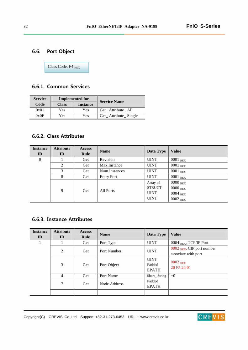
Class Code: F4 HEX
6.6. Port Object
6.6.1. Common Services
Service
Code
Implemented for Service Name
Class Instance
0x01 Yes Yes Get_ Attribute_ All
0x0E Yes Yes Get_ Attribute_ Single
6.6.2. Class Attributes
Instance
ID
Attribute
ID
Access
Rule Name Data Type Value
0 1 Get Revision UINT 0001 HEX
2 Get Max Instance UINT 0001 HEX
3 Get Num Instances UINT 0001 HEX
8 Get Entry Port UINT 0001 HEX
9 Get All Ports
Array of
STRUCT
UINT
UINT
0000 HEX
0000 HEX
0004 HEX
0002 HEX
6.6.3. Instance Attributes
Instance
ID
Attribute
ID
Access
Rule Name Data Type Value
1 1 Get Port Type UINT 0004 HEX, TCP/IP Port
2 Get Port Number UINT 0002 HEX, CIP port number
associate with port
3 Get Port Object
UINT
Padded
EPATH
0002 HEX
20 F5 24 01
4 Get Port Name Short_ String =0
7 Get Node Address Padded
EPATH

33 FnIO EtherNET/IP Adapter NA-9188 FnIO S-Series
Copyright(C) CREVIS Co.,Ltd Support +82-31-273-6453 URL : www.crevis.co.kr
Class Code : F5 HEX
6.7. TCP/IP Object
6.7.1. Common Services
Service
Code
Implemented for Service Name
Class Instance
0x01 Yes Yes Get_ Attribute_ All
0x0E Yes Yes Get_ Attribute_ Single
0x02 No Yes Set_ Attribute_ All
0x10 No Yes Set_ Attribute_ Single
6.7.2. Class Attributes
Instance
ID
Attribute
ID
Access
Rule Name Data Type Value
0 1 Get Revision UINT 0001 HEX
2 Get Max Instance UINT 0001 HEX
3 Get Num Instances UINT
6.7.3. Instance Attributes
Instance
ID
Attribute
ID
Access
Rule Name Data Type Value
1 1 Get Status DWORD 00000001 HEX
2 Get Configuration Capability DWORD 00000006 HEX
3 Get / Set Configuration Control DWORD 00000010 HEX
4 Get
Physical Link Path
Size of Path
Path
STRUCT of:
UINT
Padded
PATH
20 F6 24 01
0000 HEX
5 Get / Set
Interface Configuration
IP address
Network Mask
Gateway Address
Name Server
Name server 2
Domain name
STRUCT of:
UDINT
UDINT
UDINT
UDINT
UDINT
STRING
6 Get / Set HOST Name STRING EthernetIP Adapter

34 FnIO EtherNET/IP Adapter NA-9188 FnIO S-Series
Copyright(C) CREVIS Co.,Ltd Support +82-31-273-6453 URL : www.crevis.co.kr
Class Code: F6 HEX
6.8. EtherNET/IP Object
6.8.1. Common Services
Service
Code
Implemented for Service Name
Class Instance
0x01 Yes Yes Get_ Attribute_ All
0x0E Yes Yes Get_ Attribute_ Single
6.8.2. Class Attributes
Instance
ID
Attribute
ID
Access
Rule Name Data Type Value
0 1 Get Revision UINT 0002 HEX
2 Get Max Instance UINT 0001 HEX
3 Get Num Instances UINT 0001 HEX
6.8.3. Instance Attributes
Instance
ID
Attribute
ID
Access
Rule Name Data Type Value
1 1 Get Interface Speed UDINT 10 DEC, 100 DEC
2 Get Interface Flags DWORD
Bit 0 : Link Active
Bit 1 : Full Duplex
Bit 2~4 : Auto negotiation
Bit 5 : Manual Setting required
Reset
Bit 6 : Local Hardware Fault
Others : 0
3 Get Physical Address Array of
6 USINTs Same as MAC address

35 FnIO EtherNET/IP Adapter NA-9188 FnIO S-Series
Copyright(C) CREVIS Co.,Ltd Support +82-31-273-6453 URL : www.crevis.co.kr
Class Code: 70 HEX
6.9. FnBus Manager Object
6.9.1. Common Services
Service
Code
Implemented for Service Name
Class Instance
0x0E No Yes Get_ Attribute_ Single
0x10 No Yes Set_ Attribute_ Single
6.9.2. Class Attributes
None
6.9.3. Instance Attributes
Instance
ID
Attribute
ID
Access
Rule Name Data Type Value
1 1 Get Number of Slot USINT (include deactivated slot)
2 Get Num of Activated Slot USINT
3 Get Num of Deactivated Slot USINT
4 Get External IDs Array of
33 BYTE
See Table 6.9.6.
See Appendix A.1.
5 Get / Set*
Selection of Input
(Produced) Process
Image Mode
USINT
See Table 6.9.1.
Valid value range is 0,1,2,3
(default 2)
6 Get / Set*
Selection of Output
(Consumed) Process
Image Mode
USINT
See Table 6.9.2.
Valid value range is 0,1
(default 0)
7 Get / Set* Slot Active Flag See Table 6.9.3
8 Get Slot Live List See Table 6.9.4
9 Get Slot Alarm List See Table 6.9.5
10 Get FnBus Status USINT
0: Normal Operation
1: FnBus Standby
2: FnBus Connection Fault
3: Expansion Configuration
Fault
4: No Expansion Module
11 Get Input (Produced) Byte
Size UINT Read IO input data size
12 Get Output (Consumed) Byte UINT Read IO output data size

36 FnIO EtherNET/IP Adapter NA-9188 FnIO S-Series
Copyright(C) CREVIS Co.,Ltd Support +82-31-273-6453 URL : www.crevis.co.kr
Size
13 Get / Set*
TBD
Enable Input Run/Idle
Header (Default) BOOL
0:Disabled
1:Enabled Input Run/Idle
Header
14 Get / Set*
TBD
Enable Output Run/Idle
Header (Default) BOOL
0:Disabled
1:Enabled Output Run/Idle
Header
32 Get Real IO Input Data Array of
BYTE Real IO Input Data
33 Get / Set Real IO Output Data Array of
BYTE Real IO Output Data
*After the system is reset, the new “Set Value” action is applied.
If changed slot location, set default value automatically.
Table 6.9.1. Selection of Input (Produced) Process Image Mode
Selection Input
Image Mode Description
0 Status(2byte) + Uncompressed Input Processing Data (default)
1 Status(2byte) + Compressed Input Processing Data
2 Uncompressed Input Processing Data default
3 Compressed Input Processing Data
Table 6.9.2. Selection of Output (Consumed) Process Image Mode
Selection Input
Image Mode Description
0 Uncompressed Output Processing Data (default) default
Table 6.9.3. Slot Active Flag
DWORD (32bits) Decimal Bit Description
Get/Set
Bit 00 Activate/Deactivate flag for slot position #1 (0:Active, 1:Decative)
Bit 01 Activate/Deactivate flag for slot position #2 (0:Active, 1:Decative)
Bit 02 Activate/Deactivate flag for slot position #3 (0:Active, 1:Decative)
.
.
.
.
.
.
Bit 30 Activate/Deactivate flag for slot position #31 (0:Active, 1:Decative)
Bit 31 Activate/Deactivate flag for slot position #32 (0:Active, 1:Decative)

37 FnIO EtherNET/IP Adapter NA-9188 FnIO S-Series
Copyright(C) CREVIS Co.,Ltd Support +82-31-273-6453 URL : www.crevis.co.kr
Table 6.9.4. Slot Live List
DWORD (32bits) Decimal Bit Description
Get
Bit 00 This bit is set (1) when slot position #1 is available to exchange IO
Bit 01 This bit is set (1) when slot position #2 is available to exchange IO
Bit 02 This bit is set (1) when slot position #3 is available to exchange IO
.
.
.
.
.
.
Bit 30 This bit is set (1) when slot position #31 is available to exchange IO
Bit 31 This bit is set (1) when slot position #32 is available to exchange IO
Table 6.9.5. Slot Alarm List
DWORD (32bits) Decimal Bit Description
Get
Bit 00 This bit is set (1) when an error is detected in slot position #1
Bit 01 This bit is set (1) when an error is detected in slot position #2
Bit 02 This bit is set (1) when an error is detected in slot position #3
.
.
.
.
.
.
Bit 30 This bit is set (1) when an error is detected in slot position #31
Bit 31 This bit is set (1) when an error is detected in slot position #32
Table 6.9.6. External IDs (=Expansion Module ID)
Byte Description
0 Network Adapter Module External ID = 0x00
1 External ID for slot position #1
2 External ID for slot position #2
3 External ID for slot position #3
4 External ID for slot position #4
5 External ID for slot position #5
6 External ID for slot position #6
7 External ID for slot position #7
8 External ID for slot position #8
9 External ID for slot position #9
10 External ID for slot position #10

38 FnIO EtherNET/IP Adapter NA-9188 FnIO S-Series
Copyright(C) CREVIS Co.,Ltd Support +82-31-273-6453 URL : www.crevis.co.kr
11 External ID for slot position #11
12 External ID for slot position #12
13 External ID for slot position #13
14 External ID for slot position #14
15 External ID for slot position #15
16 External ID for slot position #16
17 External ID for slot position #17
18 External ID for slot position #18
19 External ID for slot position #19
20 External ID for slot position #20
21 External ID for slot position #21
22 External ID for slot position #22
23 External ID for slot position #23
24 External ID for slot position #24
25 External ID for slot position #25
26 External ID for slot position #26
27 External ID for slot position #27
28 External ID for slot position #28
29 External ID for slot position #29
30 External ID for slot position #30
31 External ID for slot position #31
32 External ID for slot position #32

39 FnIO EtherNET/IP Adapter NA-9188 FnIO S-Series
Copyright(C) CREVIS Co.,Ltd Support +82-31-273-6453 URL : www.crevis.co.kr
Class Code: 71 HEX
6.10. Expansion Slot Object
6.10.1. Common Services
Service
Code
Implemented for Service Name
Class Instance
0x0E No Yes Get_ Attribute_ Single
0x10 No Yes Set_ Attribute_ Single
6.10.2. Class Attributes
None
6.10.3. Instance Attributes
Instance
ID
Attribute
ID
Access
Rule Name Data Type Value
1~32
(slot No.)
1 Get Module External ID USINT See Appendix A.1.
2 Get
I/O Data Code
- Input Data Code
- Output Data Code
STRUCT of:
USINT
USINT
See Table 6.10.1.
3 Get
Input Offset Table
- Byte Offset
- Bit Offset
STRUCT of:
USINT
USINT
Byte offset in the Input
Assembly Corresponding bit
offset in the byte (If Input data
length is zero, then return
Empty.)
4 Get
Output Offset Table
- Byte Offset
- Bit Offset
STRUCT of:
USINT
USINT
Byte offset in the Output
Assembly Corresponding bit
offset in the byte (If Output data
length is zero, then return
Empty.)
5 Get Input Data Array of:
BYTE
Read Input data size defined by
attributes 2.
If Input data length is zero, then
return Empty.
6 Get/Set Output Data Array of:
BYTE
Read/Write Output data size
defined by attributes 2.
If Output data length is zero,
then return Empty.
7 Get/Set* Active Flag BOOL 0: This slot is activated
1: This slot is deactivated

40 FnIO EtherNET/IP Adapter NA-9188 FnIO S-Series
Copyright(C) CREVIS Co.,Ltd Support +82-31-273-6453 URL : www.crevis.co.kr
8 Get Configuration
Parameter Data length USINT
See
“FnIO_Configuration_Paramete
r_Memory_Register_Rev1.01”
9 Get/Set R/W Configuration Data n Bytes Data array size defined by
attributes 8.
10 Get Register Data Length USINT
See
“FnIO_Configuration_Paramete
r_Memory_Register_Rev1.01”
11 Get/Set
R/W Register Data
- Offset Low
- Offset High
- R/W Length
- Write Data
STRUCT of:
USINT
USINT
USINT
n Bytes
Read data array size defined by
attribute 10.
. R/W Length ≤ 32byte
. Offset + Length ≤ attribute 9
15 Get/Set
R/W Maintenance Data
- Module Serial ID
- Offset
- R/W Length
- Write Data
STRUCT of:
USINT
USINT
USINT
n Bytes
Vendor only
Module Serial ID = Attribute 1
R/W Length ≤ 32byte
100 Get Product Code 4 Bytes See Table 6.10.2. and Appendix
A.1.
101 Get Catalog Number 4 Bytes See Appendix A.1.
102 Get Firmware Revision
STRUCT of:
USINT
USINT
Expansion Module Firmware
Revision
*After the system is reset, the new “Set Value” action is applied.
If changed slot location, set default value automatically.

41 FnIO EtherNET/IP Adapter NA-9188 FnIO S-Series
Copyright(C) CREVIS Co.,Ltd Support +82-31-273-6453 URL : www.crevis.co.kr
Table 6.10.1. I/O Data Code Format
Byte # Bit 7 Bit 6 Bit 5 Bit 4 Bit 3 Bit 2 Bit 1 Bit 0
0 Input Data Type Input Data Length
1 Output Data Type Output Data Length
Input / Output Type :
0 0: No I/O Data
0 1: Byte Data
1 0: Word Data
1 1: Bit Data
Input / Output Data Length:
0 0 0 0 0 0 0: 0 Bit/Byte/Word
0 0 0 0 0 0 1: 1 Bit/Byte/Word
0 0 0 0 0 1 0: 2 Bit/Byte/Word
0 0 0 0 0 1 1: 3 Bit/Byte/Word
…
1 1 1 1 1 1 1: 63 Bit/Byte/Word
Table 6.10.2. Product Code Format
Byte # Bit 7 Bit 6 Bit 5 Bit 4 Bit 3 Bit 2 Bit 1 Bit 0
0 Connection Type
1 Assembly Type
2 Output Information
3 Input Information
Connection Type
Byte # Bit 7 Bit 6 Bit 5 Bit 4 Bit 3 Bit 2 Bit 1 Bit 0
0 Reserved MEM IO
IO (Input / Output Connection) :
IO = 0: does not support Input / Output Connection
IO = 1: support Input / Output Connection
MEM (Memory Register Service) :
MEM = 0: does not support Memory Register Service Connection
MEM = 1: support Memory Register Service Connection

42 FnIO EtherNET/IP Adapter NA-9188 FnIO S-Series
Copyright(C) CREVIS Co.,Ltd Support +82-31-273-6453 URL : www.crevis.co.kr
Assembly Type
Byte # Bit 7 Bit 6 Bit 5 Bit 4 Bit 3 Bit 2 Bit 1 Bit 0
1 Unit_ Type Priority S Reserved
Unit_ Type :
0 0: Not Used
0 1: Input Module
1 0: Output Module
1 1: I/O Both Modules
Priority (Input / Output Data Priority for assembly) :
0 0: Priority 0 (low) - usually it is used by Byte/Bit Type Discrete module.
0 1: Priority 1
1 0: Priority 2 - usually it is used by Analog I/O module.
1 1: Priority 3 (high)
S (Status for Ethernet Slot Diagnostic) :
0: No Status
1: Support Word Input Diagnostic (0x8000 = -32678)
for example: ST-3234(current analog input 4~20mA, 14bit)
Status Input Data
Normal 0x0000 (4mA) ~ 0x3FFF (20mA)
Open Wire or Underage (0~3mA) 0x8000 (-32678)

43 FnIO EtherNET/IP Adapter NA-9188 FnIO S-Series
Copyright(C) CREVIS Co.,Ltd Support +82-31-273-6453 URL : www.crevis.co.kr
Input / Output Information
Byte # Bit 7 Bit 6 Bit 5 Bit 4 Bit 3 Bit 2 Bit 1 Bit 0
2(Output) Data_ Type Data_ Length
3(Input) Data_ Type Data_ Length
Data_ Type :
0 0: Byte Data
0 1: Word Data
1 0: Bit Data
1 1: have no Input or Output Data
Data_ Length :
0 0 0 0 0 0 0: 1 Bit/Byte/Word
0 0 0 0 0 0 1: 2 Bit/Byte/Word
0 0 0 0 0 1 0: 3 Bit/Byte/Word
0 0 0 0 0 1 1: 4 Bit/Byte/Word
0 0 0 0 1 0 0: 5 Bit/Byte/Word
0 0 0 0 1 0 1: 6 Bit/Byte/Word
0 0 0 0 1 1 0: 7 Bit/Byte/Word
0 0 0 0 1 1 1: 8 Byte/Word
0 0 0 1 0 0 0: 9 Byte/Word
……
1 1 1 1 1 1 0: 63 Byte/Word
1 1 1 1 1 1 1: 64 Byte/Word
6.11. Ethernet/IP Reference
Ethernet/IP Reference Documents
http://www.odva.org
http://www.ethernet-ip.org
Ethernet/IP Tools
http://www.pyramid-solutions.com

44 FnIO EtherNET/IP Adapter NA-9188 FnIO S-Series
Copyright(C) CREVIS Co.,Ltd Support +82-31-273-6453 URL : www.crevis.co.kr
7. Trouble Shooting
7.1. How to diagnose by LED indicator
LED Status Cause Action
All LED turns off
- No power - Check main power Cable
- System power is not supplied. - Contact Sales team and send module
for repair.
MOD LED flashes green - Failure of initialization EEPROM
parameter.
- Contact Sales team and send module
for repair.
MOD LED flashes red
- Excess of expansion slot
- Excess of IO size
- Wrong IO composition
- Occurrence of EEPROM checksum
error
- Use expansion slot up to 32.
- Compose that IO total size is not
excess.
- Check composition I/O Module
MOD LED is red - Wrong address ID
- Occurrence critical error in firmware
- Contact Sales team and send module
for repair.
I/O LED turns off - Failure of realization expansion Module
- None expansion Module
- Check connector status both NA
series and expansion module.
I/O LED flashes red
Failure of configuration baud rate
- Check communication cable with
Master
- Check power for master.
Failure of initialization I/O
- Use expansion slot up to 32.
- Compose that IO total size is not
excess.
NA series notice unidentified
expansion module ID. Check status of
expansion module.
I/O LED is red Failure of exchanging I/O data Check status of expansion IO
connection.
NET LED turns off Failure of communication with Master Check main power for master and
communication cable.
NET LED flashed green Failure of exchanging data with master Check status in software for Master
configuration.
NET LED is red Communication connecting lost
Check BUS line cable for connection
with master.
Check duplication address.

45 FnIO EtherNET/IP Adapter NA-9188 FnIO S-Series
Copyright(C) CREVIS Co.,Ltd Support +82-31-273-6453 URL : www.crevis.co.kr
7.2. How to diagnose when device couldn’t communicate network
Inspection of wrong or omission cable connection.
- Check status of cable connection for each node.
- Check that all color matches between connector and cable.
- Check wire omission.
Terminator resistor
- If terminator resistor is not installed, install terminator resistor
- Check location of terminator resistor
Configuration of Node address
- Check duplication node address.
Configuration of Master
- Check configuration of master
- Check whether to do download or don’t
- Check composition is right
Configuration of communication baud rate
I/O size
Configuration of each node
Ground and environment
- Check ground is contacted
- Check environment factor (temperature, humidity, etc.) is in less than regular limit
46 FnIO EtherNET/IP Adapter NA-9188 FnIO S-Series
Copyright(C) CREVIS Co.,Ltd Support +82-31-273-6453 URL : www.crevis.co.kr
APPENDIX A
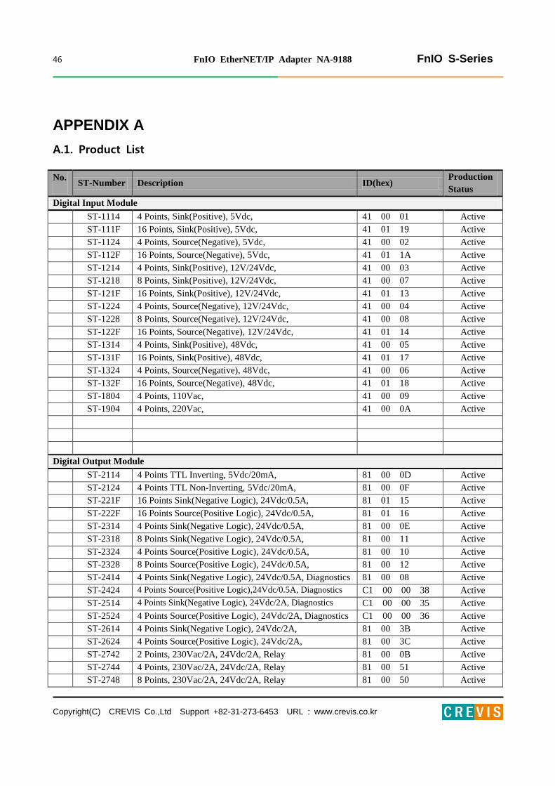
A.1. Product List
No. ST-Number Description ID(hex)
Production
Status
Digital Input Module
ST-1114 4 Points, Sink(Positive), 5Vdc, 41 00 01 Active
ST-111F 16 Points, Sink(Positive), 5Vdc, 41 01 19 Active
ST-1124 4 Points, Source(Negative), 5Vdc, 41 00 02 Active
ST-112F 16 Points, Source(Negative), 5Vdc, 41 01 1A Active
ST-1214 4 Points, Sink(Positive), 12V/24Vdc, 41 00 03 Active
ST-1218 8 Points, Sink(Positive), 12V/24Vdc, 41 00 07 Active
ST-121F 16 Points, Sink(Positive), 12V/24Vdc, 41 01 13 Active
ST-1224 4 Points, Source(Negative), 12V/24Vdc, 41 00 04 Active
ST-1228 8 Points, Source(Negative), 12V/24Vdc, 41 00 08 Active
ST-122F 16 Points, Source(Negative), 12V/24Vdc, 41 01 14 Active
ST-1314 4 Points, Sink(Positive), 48Vdc, 41 00 05 Active
ST-131F 16 Points, Sink(Positive), 48Vdc, 41 01 17 Active
ST-1324 4 Points, Source(Negative), 48Vdc, 41 00 06 Active
ST-132F 16 Points, Source(Negative), 48Vdc, 41 01 18 Active
ST-1804 4 Points, 110Vac, 41 00 09 Active
ST-1904 4 Points, 220Vac, 41 00 0A Active
Digital Output Module
ST-2114 4 Points TTL Inverting, 5Vdc/20mA, 81 00 0D Active
ST-2124 4 Points TTL Non-Inverting, 5Vdc/20mA, 81 00 0F Active
ST-221F 16 Points Sink(Negative Logic), 24Vdc/0.5A, 81 01 15 Active
ST-222F 16 Points Source(Positive Logic), 24Vdc/0.5A, 81 01 16 Active
ST-2314 4 Points Sink(Negative Logic), 24Vdc/0.5A, 81 00 0E Active
ST-2318 8 Points Sink(Negative Logic), 24Vdc/0.5A, 81 00 11 Active
ST-2324 4 Points Source(Positive Logic), 24Vdc/0.5A, 81 00 10 Active
ST-2328 8 Points Source(Positive Logic), 24Vdc/0.5A, 81 00 12 Active
ST-2414 4 Points Sink(Negative Logic), 24Vdc/0.5A, Diagnostics 81 00 08 Active
ST-2424 4 Points Source(Positive Logic),24Vdc/0.5A, Diagnostics C1 00 00 38 Active
ST-2514 4 Points Sink(Negative Logic), 24Vdc/2A, Diagnostics C1 00 00 35 Active
ST-2524 4 Points Source(Positive Logic), 24Vdc/2A, Diagnostics C1 00 00 36 Active
ST-2614 4 Points Sink(Negative Logic), 24Vdc/2A, 81 00 3B Active
ST-2624 4 Points Source(Positive Logic), 24Vdc/2A, 81 00 3C Active
ST-2742 2 Points, 230Vac/2A, 24Vdc/2A, Relay 81 00 0B Active
ST-2744 4 Points, 230Vac/2A, 24Vdc/2A, Relay 81 00 51 Active
ST-2748 8 Points, 230Vac/2A, 24Vdc/2A, Relay 81 00 50 Active

47 FnIO EtherNET/IP Adapter NA-9188 FnIO S-Series
Copyright(C) CREVIS Co.,Ltd Support +82-31-273-6453 URL : www.crevis.co.kr
ST-2792 2 Points, 230Vac/2A, 24Vdc/2A, Relay, Manual/Auto C1 00 01 BE Active
ST-2852 2 Points, 12~125Vac/0.5A, Triac 81 00 0C Active
ST-2924 4 Points, 24Vac/2A, 24Vdc/2A, 4 Points/4COM 81 00 C0 NEW
ST-2944 4 Points, 24Vac/2A, 24Vdc/2A, 1 Points/1COM 81 00 C1 NEW
ST-2734 4 Points, 24~220Vac,dc/0.5A, 1 Points/1COM 81 00 C2 NEW
Analog Input Module
ST-3114 4 Channels, Current, 0~20mA, 12bit 41 43 1C Active
ST-3118 8 Channels, Current, 0~20mA, 12bit 41 47 82 Active
ST-3134 4 Channels, Current, 0~20mA, 14bit 41 43 1E Active
ST-3214 4 Channels, Current, 4~20mA, 12bit 41 43 1D Active
ST-3218 8 Channels, Current, 4~20mA, 12bit 41 47 83 Active
ST-3234 4 Channels, Current, 4~20mA, 14bit 41 43 1F Active
ST-3274 4 Channels, Current, 4~20mA, 12bit, Sensor Connector 41 43 A3 Active
ST-3424 4 Channels, Voltage, 0~10Vdc, 12bit 41 43 20 Active
ST-3428 8 Channels, Voltage, 0~10Vdc, 12bit 41 47 22 Active
ST-3444 4 Channels, Voltage, 0~10Vdc, 14bit 41 43 22 Active
ST-3474 4 Channels, Voltage, 0~10Vdc, 12bit, Sensor Connector 41 43 A0 Active
ST-3524 4 Channels, Voltage, -10Vdc~10Vdc, 12bit 41 43 21 Active
ST-3544 4 Channels, Voltage, -10Vdc~10Vdc, 14bit 41 43 23 Active
ST-3624 4 Channels, Voltage, 0~5Vdc, 12bit 41 43 24 Active
ST-3644 4 Channels, Voltage, 0~5Vdc, 14bit 41 43 25 Active
ST-3702 2 Channels, RTD, Status 41 41 28 Active
ST-3704 4 Channels, RTD, Status 41 43 64 Active
ST-3708 8 Channels, RTD, Status 41 47 65 Active
ST-3802 2 Channels, TC 41 41 2A Active
ST-3804 4 Channels, TC 41 43 66 Active
ST-3808 8 Channels, TC 41 47 67 Active
Analog Output Module
ST-4112 2 Channels, Current, 0~20mA, 12bit 81 41 2C Active
ST-4114 4 Channels, Current, 0~20mA, 12bit 81 43 6D Active
ST-4212 2 Channels, Current, 4~20mA, 12bit 81 41 2D Active
ST-4214 4 Channels, Current, 4~20mA, 12bit 81 43 6E Active
ST-4274 4 Channels, Current, 4~20mA, 12bit, Sensor Connector 81 43 B3 Active
ST-4422 2 Channels, Voltage, 0~10Vdc, 12bit 81 41 2E Active
ST-4424 4 Channels, Voltage, 0~10Vdc, 12bit 81 43 6A Active
ST-4474 4 Channels, Voltage, 0~10Vdc, 12bit, Sensor Connector 81 43 B0 Active
ST-4491 1 Channel, Voltage, 0~10Vdc, 12bit, Manual Type C1 40 41 BF Active
ST-4522 2 Channels, Voltage, -10~10Vdc, 12bit 81 41 2F Active
ST-4622 2 Channels, Voltage, 0~5Vdc, 12bit 81 41 30 Active
ST-4911 1 Channel, Current, 0~1A, 12bit 81 40 31 Active
48 FnIO EtherNET/IP Adapter NA-9188 FnIO S-Series
Copyright(C) CREVIS Co.,Ltd Support +82-31-273-6453 URL : www.crevis.co.kr
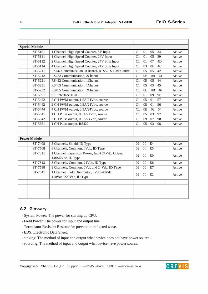
Special Module
ST-5101 1 Channel, High Speed Counter, 5V Input C1 01 05 34 Active
ST-5111 1 Channel, High Speed Counter, 24V Input C1 01 05 39 Active
ST-5112 2 Channel, High Speed Counter, 24V Sink Input C1 01 07 4D Active
ST-5114 4 Channel, High Speed Counter, 24V Sink Input C1 03 0F 4C Active
ST-5211 RS232 Communication, 1Channel, RTS/CTS Flow Control C1 05 05 42 Active
ST-5212 RS232 Communication, 2Channel C1 0B 0B 43 Active
ST-5221 RS422 Communication, 1Channel C1 05 05 44 Active
ST-5231 RS485 Communication, 1Channel C1 05 05 45 Active
ST-5232 RS485 Communication, 2Channel C1 0B 0B 46 Active
ST-5351 SSI Interface 1CH C1 01 09 9E Active
ST-5422 2 CH PWM output, 1.5A/24Vdc, source C1 05 01 57 Active
ST-5442 2 CH PWM output, 0.5A/24Vdc, source C1 05 01 56 Active
ST-5444 4 CH PWM output, 0.5A/24Vdc, source C1 0B 03 54 Active
ST-5641 1 CH Pulse output, 0.5A/24Vdc, source C1 05 03 92 Active
ST-5642 2 CH Pulse output, 0.5A/24Vdc, source C1 09 07 90 Active
ST-5651 1 CH Pulse output, RS422 C1 05 03 98 Active
Power Module
ST-7408 8 Channels, Shield, ID Type 02 00 E4 Active
ST-7508 8 Channels, Common, 0Vdc, ID Type 02 00 E5 Active
ST-7511 1 Channel, Expansion Power, Input 24Vdc, Output
1.0A/5Vdc, ID Type 02 00 E0 Active
ST-7518 8 Channels, Common, 24Vdc, ID Type 02 00 E6 Active
ST-7588 8 Channels, Common, 0Vdc and 24Vdc, ID Type 02 00 E7 Active
ST-7641 1 Channel, Field Distributor, 5Vdc~48Vdc,
110Vac~220Vac, ID Type 02 00 E2 Active
A.2. Glossary
- System Power: The power for starting up CPU.
- Field Power: The power for input and output line.
- Terminator Resistor: Resistor for prevention reflected wave.
- EDS: Electronic Data Sheet.
- sinking: The method of input and output what device does not have power source.
- sourcing: The method of input and output what device have power source.