focs-n 2022 4822 en - kalor krakówkalor.com.pl/upload/dokumentacja techniczna_focs-n...
TRANSCRIPT
High effi ciency Compactness Extensive range of operation Hot water supply
Reversible unit, air source for outdoor installation
(The photo of the unit is indicative and may change depending on the model)
2022 - 4822450 - 1162 kW
FOCS-N
FOCS-N_2022_4822_201211_EN Climaveneta Technical Bulletin
Please fill out the requested informationPlease fill out the requested information
II FOCS-N_2022_4822
FOCS-N
HFC R134a
SUMMARY FOCS-N2022 - 4822
Liability disclaimerThis bulletin is not exhaustive about: installation, use, safety precautions, handling and transport. Refer to the “General Manual of Installation” for further information.This bulletin refers to standard executions, particularly as re-gards dimensions, weight, electric, hydraulic, aeraulic and re-frigerant connections (where applicable). Contact Climaveneta Commercial Offi ce for further drawings and schemes.
Climaveneta declines any liability deriving from use of the bul-letin.This bulletin is the exclusive property of Climaveneta and all forms of copy are prohibited.The data contained herein are subject to change without no-tice.
1. Product presentation 1.2 High effi cieny 1.3 Compactness 1.4 Extensive range of operation 1.5 Hot water supply
2. Unit description 2.2 Standard unit composition 2.3 Certifi cations 2.4 Units’ tests 2.5 Available confi gurations 2.6 Available versions 2.7 W3000SE Large electronic controller 2.8 Accessories 2.9 Group regulation device 2.10 Supervisory device
3. Technical data 3.1 General technical data
4. Selection limits 5. Hydraulic data
5.1 Water fl ow and pressure drop 5.2 Hydronic group
6. Electrical data 7. Full load sound level 8. Dimensional drawings 9. Variable fl ow hydronic group
9.1 VPF Systems 9.2 VPF.D Systems
pg. n° III pg. n° III pg. n° III pg. n° III pg. n° III pg. n° 1 pg. n° 1 pg. n° 2 pg. n° 2 pg. n° 2 pg. n° 2 pg. n° 2 pg. n° 3 pg. n° 4 pg. n° 5 pg. n° 6 pg. n° 6 pg. n° 14 pg. n° 17 pg. n° 17 pg. n° 19 pg. n° 25 pg. n° 29 pg. n° 33 pg. n° A1 pg. n° A1 pg. n° A4
Company quality system certifi ed to UNI EN ISO 9001
and environmental certifi cation UNI EN ISO 14001
This company participates in the Eurovent Certifi cation Pro-gramme. The products are listed in the Directory of certifi ed products. Eurovent certifi cation applied to units with cooling capacity up to 1500 kW for air cooled water chillers and water cooled liquid chillers.
Please fill out the requested informationPlease fill out the requested information
III FOCS-N_2022_4822
FOCS-N
HFC R134a
Outdoor heat pump unit for the production of chilled/hot water
with semi-hermetic screw compressors optimized for R134a,
axial-fl ow fans, external coil with copper tubes and aluminium
fi nes, shell and tubes heat exchanger designed by Climavene-
ta and electronic expansion valve. Base and supporting struc-
ture and panels are galvanized epoxy powder coated steel with
increased thickness. These units are designed for two-pipes
systems and are able to produce hot or cold water according
to the selected operation mode; the precise thermoregulation
guarantees an optimal response to load´s changes, in every
operating conditions.
1.2 High effi cieny
Unit in Class A as per Eurovent. High effi ciency for low energy
consumption during the operating hours.
1.3 Compactness
Reduced dimensions, for easy installation even in sites with
space´ constraints.
1.4 Extensive range of operation
Unit´s operation guaranteed with external air temperature down
to -10°C during winter and up to 46°C during summer.
1.5 Hot water supply
Supply of hot water in use up to 55°C, offering maximum versa-
tility with respect to different plant engineering solutions.
1. PRODUCT PRESENTATION
1 FOCS-N_2022_4822
FOCS-N
HFC R134a
2.1 Chiller, air source for outdoor installation
Outdoor heat pump unit for the production of chilled/hot water
with semi-hermetic screw compressors optimized for R134a,
axial-fl ow fans, external coil with copper tubes and aluminium
fi nes, shell and tubes heat exchanger designed by Climaveneta
and electronic expansion valve. Base and supporting structu-
re and panels are galvanized epoxy powder coated steel with
increased thickness. These units are designed for two-pipes
systems and are able to produce hot or cold water according
to the selected operation mode; the precise thermoregulation
guarantees an optimal response to load´s changes, in every
operating conditions.
The unit is supplied fully refrigerant charged and factory tested.
On site installation only requires power and hydraulic connec-
tion.
2.2 Standard unit composition
Structure
Base and frame in galvanized steel. The supporting frame are
polyester-painted for the highest resitance to external factors:
surfaces´ hue and brightness are preserved. In silenced ver-
sions, pipes and compressors´ box are covered with an acous-
tic layer to reduce global noise emissions.
Screw compressors
New semi-hermetic screw compressors designed for high ef-
fi ciency both at full and partial load. Semi-hermetic screw com-
pressors with 2 fi ve- and six-lobe rotors: the fi ve-lobe rotor is
splined directly onto the motor (nominal speed 2950 rpm) with-
out the use of interposed overgears.
The bearings provided along the rotor axis in a separate cham-
ber isolated from the compression chamber are made in carbon
steel.
Each compressor is provided with an inlet for refrigerant injec-
tion (for the extension of operating limits) and the use of the
economiser (for the output capacity and effi ciency´s increase).
Optimized lubrication guarantees oil´s distribution between me-
chanical parts, without using an oil pump; the built-in oil sepa-
rator has 3 stages of separation, and a 10 mm stainless steel
mesh fi lter ensures the constant presence of oil inside. Cooling
power is partialized by a slide valve, which depending on the
position assumed, permits a stepless compression chamber
reduction; each compressor can therefore continuosly partial-
ize from 50% to 100% of its capacity. The two pole motors are
fi tted as standard with electric devices to limit the absorbed
current during compressor start-up, and with empty start-up.
Each compressor is fi tted with manual-reset motor thermal pro-
tection, delivery gas temperature and oil level controls and an
electric resistance for the carter´s heating while the compressor
is stopped. A check valve fi tted on the refrigerant delivery line
prevents the rotors from reversing after stopping. On-off cocks
on the delivery line of each compressor to isolate the refriger-
ant charge in the heat exchanger when required. Compressors
star-delta start.
Plant side heat exchanger
Shell and tube heat exchanger; it acts as an evaporator or as
a condenser depending to the unit´s commutation; refrigerant
fl ows inside the pipes and water fl ow on the shell side. The
tubes have asymmetrical fl ows that maintain the correct speed
of the refrigerant in the tubes during phase transition. The water
fl ows on the shell side is fi tted with baffl es to increase turbulence
and therefore the effi ciency of exchange. The steel shell has
external foamed closed-cell elastomer insulating lining 10 mm
thick and thermal conductivity of 0.033 W/mK at 0°C. The tube
nest is manufactured using copper tubes with internal grooves
for favouring heat exchange and mechanically expanded onto
the tube plates. The heat exchanger is fi tted with a differential
pressure switch which controls the fl ow of water when the unit
is working, in this way preventing anomalies and overheating.
In other case, when the unit is off, an electrical heater prevents
ice-formation. The heat exchanger is made in compliance with
PED standard work pressure requisites.
Source side heat exchanger
Air-refrigerant heat exchager, working as a condenser or an
evaporator depending to the specifi c operating mode. Made
with copper tubes and aluminium fi ns. The aluminium fi ns are
spaced to guarantee the best heat exchange effi ciency. The
lower part of the exchanger works as a subcooling circuit in-
creasing the cooling capacity, when it is working as a condens-
er.
Fan section source side
Axial electric fans, system of protection IP54 and “F” insulation
class, with external rotor, profi led die-cast aluminium blades,
housed in aeodynamic hoods complete with guard grille. 6-poles
electric motor with built-in thermal protection. Variable Speed
low-temperature Device (DVV) to control condensation adjust-
ing the rotational speed with voltage steps (auto-transformer) is
standard for all versions.
Refrigerant circuit
The unit has two completely independent cooling circuits in or-
der to ensure continuous operation, limited pollution, and easy
maintenance.
Each cooling circuit is fi tted as standard with:
- economizers
- externally equalised electronic expansion valve
- reversing cycle valve
- high and low pressure safety valves
- high and low pressure transducers
- check valve on the compressor delivery line
- on-off cock on the compressor´s suction and delivery line and
on the refrigerant line
- solenoid valve on the refrigerant line
- dryer fi lter with replaceable cartridge
- refrigerant line sight glass with humidity indicator
- high-pressure safety pressure-switch
- liquid receivers
- liquid separators.
Electric power and control panel
Electric power and control panel compliant with EN 60204-1/
IEC 204-1, complete with:
- electronic controller
- transformer for control circuit
- general door lock isolator
- power circuit with bar distribution system
- fuses and contactors for compressors and fans
- terminals for cumulative alarm block
- remote ON/OFF terminals
- spring-type control circuit terminal boards
- phases sequence and minimum/maximum voltage control
- electrical heaters on external coils (only on CA, LN-CA, SL-CA
versions).
Power supply 400/3/50 with star/delta start.
2. UNIT DESCRIPTION
2 FOCS-N_2022_4822
FOCS-N
HFC R134a
2.3 Certifi cations
EUROVENT Certifi cation program
CE - Product quality certifi cate for the European Union
GOST - Product quality certifi cate for Russian Federation
SAFETY QUALITY LICENCE - Product quality certifi cate for
Popular Republic of China
M&I - Product quality certifi cate for Australia and New Zealand
Machine directive 2006/42/EC
PED directive 97/23/EC
Low Voltage directive 2006/95/EC
ElectroMagnetic compatibility directive 2004/108/EC
ISO 9001 - Company´s Quality Management System certifi ca-
tion
ISO 14001 - Company´s Environmental Management System
certifi cation.
2.4 Units’ tests
Tests carried out along the all productive process as imposed
by ISO9001.
Possibility to have performance and acoustical witness tests,
with the support of qualifi ed technical operators.
Performance tests give the possibility to measure:
- electrical data
- heat exchangers´ waterfl ow
- operating temperature
- absorbed and given power, both at full load and partial load
condition, in each operating mode.
It’s even possible to have a simulation of the most common
alarms and the pressure drops (water side) measurements.
The acoustical tests allow to verify level of sound emissions of
the unit according to ISO3744.
2.5 Available confi gurations
Basic model
Reversible standard unit for production of chilled/hot water ac-
cording to the selected operation mode.
Model with partial heat recovery (D)
Reversible unit for production of chilled/hot water, complete
of an auxiliary heat exchanger on the discharge section of the
compressor to the superheat reclaim. The reclaim heat is ap-
proximately the 20% of the total cooling capacity. This function
is used for application with domestic hot water production or
other secondary uses, as support of the existing boiler.
2.6 Available versions
B (Base)
Base unit.
SL-CA (Super Low-noise version, Class A of effi ciency as
per Eurovent)
Super Low-noise version, Class A of effi ciency as per Eurov-
ent.
Acoustic insulation on the compressors box, on pipes and a low
fans´ rotational speed gives the minimization of sound emis-
sion.
CA (Class A of effi ciency)
Class A of effi ciency as per Eurovent.
LN-CA (Low-noise version, Class A of effi ciency as per Eu-
rovent)
Low-noise version, Class A of effi ciency as per Eurovent.
Acoustic insulation on the compressors box and a low fans´
rotational speed gives the minimization of sound emission.
2.7 W3000SE Large electronic controller
The W3000SE Large controller offers advanced functions and
algorithms. The keypad features an easy-to-use interface and a
complete LCD display, allowing to consult and intervene on the
unit by means of a multi-level menu, with selectable language
setting. The regulation features the continuous modulation of
capacity, based on a dynamic dead band and referring to the
leaving water temperature. As alternative, step-wise regula-
tion is also available, referred to the return water temperature
with selectable proportional- or proportional-integral logic. The
diagnostics includes a complete alarm management, with the
“black-box” and alarm logging functions for enhanced analysis
of the unit operation. For multiple units’ systems, the regulation
of the resources, via optional proprietary devices, can be imple-
mented. Energy metering, for both consumption and capacity,
can also be developed. Supervision can be easily developed
via proprietary devices or the integration in third party systems
by means of the most common protocols as ModBus, Bacnet,
Bacnet-over-IP, Echelon LonWorks. Compatibility with the re-
mote keyboard managing up to 10 units. Availability of an inter-
nal real time clock for operation scheduling (4-day profi les with
10 hour belts). The defrost adopts a proprietary self-adaptive
logic, which features the monitoring of numerous operational
parameters. This allows to reduce the number and duration
of the defrost cycles, with a benefi t for the overall energy ef-
fi ciency.
3 FOCS-N_2022_4822
FOCS-N
HFC R134a
2.8 Accessories
ACCESSORIES DESCRIPTION BENEFIT
Cu/Cu condensing coils Air-refrigerant heat exchanger with copper fi ns and
tubes.
Recommended for applications in corrosive atmos-
pheres.
Condensing coils with epoxy-coated fi ns Painted air-refrigerant heat exchanger. Recommended for applications in medium level
pollution atmospheres.
Condensing coils with Fin Guard Silver treat-
ment
Air-refrigerant heat exchanger with epoxidic treatment
on coils and fi ns.
Recommended for marine exposure conditions,
with an high level of pollution or other aggressive
atmospheres.
Soft start Electronic device adopted to manage the inrush
current.
Break down of the inrush current as soon as the elec-
trical motor is switch on, lower motor's mechanical
wear, favourable sizing for the electrical system.
Hydronic group (See dedicate section)
Variable fl ow hydronic group (See dedicate section)
kit HWT Kit for high hot primary heat exchanger leaving water
temperature up to 60°C and for high outdoor tempe-
rature: up to 50°C at full load and up to 57°C at partial
load. The accessory is required for applications with
high water temperature requestes (higher then 55°C)
or for installation in extremely hot areas.
ModBUS connectivity Interface module for ModBUS protocols. Allows integration with BMS operating with ModBUS
protocol.
BACnet connectivity Interface module for BACnet protocols. Allows integration with BMS operating with BACnet
protocol.
Echelon connectivity Interface module for Echelon systems. Allows integration with BMS operating with LonWorks
procotls.
AUXILIARY SIGNAL 4-20mA 4..20mA analogue input. Allows to change the opera-
ting set-point according to the value of current applied
to the analogue input.
Enforce Energy Saving policies.
Automatic circuit breakers Over-current switch on the major electrical loads. It protects compressors and/or fans from possible
current peaks.
Input remote demand limit Digital input (voltage free). It permits to limit the unit's power absorption for safety
reasons or in temporary situation.
EC fans Electronically commutated fans (EC fans); the
brushless motor, governed by a special controller,
continuously adjust fans' speed.
Reduced energy consumption, electromagnetic
noises and current's absorption even during start-up
phase. Noise reduces proportionally to unit's partia-
lization.
Coil protection grill in peraluman
Anti-intrusions grills Avoid the intrusion of solid bodies into the unit's
structure.
Numbered cables on electrical board
Remote signal double SP Allows to activate the Energy Saving set-point. Enforce Energy Saving policy.
Flanged evaporator connection
Evaporator fl owswitch (water side)
Container packing
Coil s protection grill and nylon coverage
Rubber anti vibration device
Spring anti vibration device
Relay for pump(s) managment Relay for the pump(s) on/off. It permits the pumps on/off. In case of 2 pumps, one
in stand-by to the other, it's possible to balance the
operating hours between them.
BACnet OVER IP connectivity Interface module for BACnet OVER-IP protocols. Allows to interconnect BACnet devices over Internet
Protocol within wide-area networks.
Double antifreeze heater
Double insulation on evaporator
DEMETRA (see dedicated manual) Software to monitor capacity and energy absorbed by
the units.
Allows a dynamic monitoring of the installed units
and therefore a data (hourly based) downloading to
support the current needs of energy management.
Network analyzer per DEMETRA Tools to measure the electricity absorbed by the unit. They meter the electricity absorbed and are connec-
ted with RS485 bus to an external device for energy
metering (DEMETRA - see dedicated manual).
Group regulation device (See dedicate section)
Supervisory device (See dedicate section)
4 FOCS-N_2022_4822
FOCS-N
HFC R134a
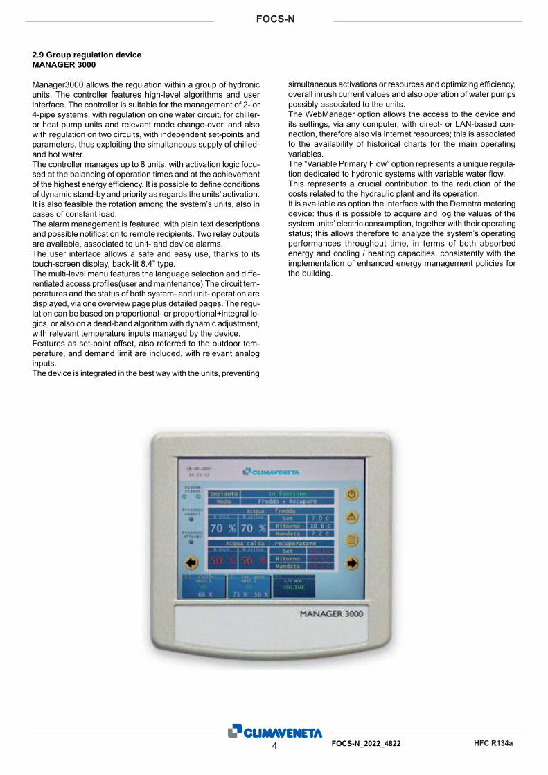
2.9 Group regulation device
MANAGER 3000
Manager3000 allows the regulation within a group of hydronic
units. The controller features high-level algorithms and user
interface. The controller is suitable for the management of 2- or
4-pipe systems, with regulation on one water circuit, for chiller-
or heat pump units and relevant mode change-over, and also
with regulation on two circuits, with independent set-points and
parameters, thus exploiting the simultaneous supply of chilled-
and hot water.
The controller manages up to 8 units, with activation logic focu-
sed at the balancing of operation times and at the achievement
of the highest energy effi ciency. It is possible to defi ne conditions
of dynamic stand-by and priority as regards the units’ activation.
It is also feasible the rotation among the system’s units, also in
cases of constant load.
The alarm management is featured, with plain text descriptions
and possible notifi cation to remote recipients. Two relay outputs
are available, associated to unit- and device alarms.
The user interface allows a safe and easy use, thanks to its
touch-screen display, back-lit 8.4” type.
The multi-level menu features the language selection and diffe-
rentiated access profi les(user and maintenance).The circuit tem-
peratures and the status of both system- and unit- operation are
displayed, via one overview page plus detailed pages. The regu-
lation can be based on proportional- or proportional+integral lo-
gics, or also on a dead-band algorithm with dynamic adjustment,
with relevant temperature inputs managed by the device.
Features as set-point offset, also referred to the outdoor tem-
perature, and demand limit are included, with relevant analog
inputs.
The device is integrated in the best way with the units, preventing
simultaneous activations or resources and optimizing effi ciency,
overall inrush current values and also operation of water pumps
possibly associated to the units.
The WebManager option allows the access to the device and
its settings, via any computer, with direct- or LAN-based con-
nection, therefore also via internet resources; this is associated
to the availability of historical charts for the main operating
variables.
The “Variable Primary Flow” option represents a unique regula-
tion dedicated to hydronic systems with variable water fl ow.
This represents a crucial contribution to the reduction of the
costs related to the hydraulic plant and its operation.
It is available as option the interface with the Demetra metering
device: thus it is possible to acquire and log the values of the
system units’ electric consumption, together with their operating
status; this allows therefore to analyze the system’s operating
performances throughout time, in terms of both absorbed
energy and cooling / heating capacities, consistently with the
implementation of enhanced energy management policies for
the building.
5 FOCS-N_2022_4822
FOCS-N
HFC R134a
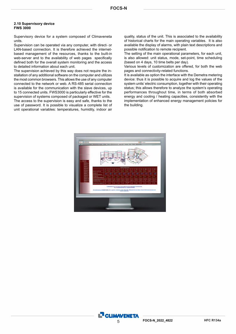
2.10 Supervisory device
FWS 3000
Supervisory device for a system composed of Climaveneta
units.
Supervision can be operated via any computer, with direct- or
LAN-based connection. It is therefore achieved the internet-
based management of the resources, thanks to the built-in
web-server and to the availability of web pages specifi cally
defi ned both for the overall system monitoring and the access
to detailed information about each unit.
The supervision achieved by this way does not require the in-
stallation of any additional software on the computer and utilizes
the most common browsers. This allows the use of any computer
connected to the network or web. A RS-485 serial connection
is available for the communication with the slave devices, up
to 15 connected units. FWS3000 is particularly effective for the
supervision of systems composed of packaged or WET units.
The access to the supervision is easy and safe, thanks to the
use of password. It is possible to visualize a complete list of
unit operational variables: temperatures, humidity, indoor air
quality, status of the unit. This is associated to the availability
of historical charts for the main operating variables. It is also
available the display of alarms, with plain text descriptions and
possible notifi cation to remote recipient.
The setting of the main operational parameters, for each unit,
is also allowed: unit status, mode, set-point, time scheduling
(based on 4 days, 10 time belts per day).
Various levels of customization are offered, for both the web
pages and connectivity-related functions.
It is available as option the interface with the Demetra metering
device: thus it is possible to acquire and log the values of the
system units’ electric consumption, together with their operating
status; this allows therefore to analyze the system’s operating
performances throughout time, in terms of both absorbed
energy and cooling / heating capacities, consistently with the
implementation of enhanced energy management policies for
the building.
FOCS-N 2022-48226
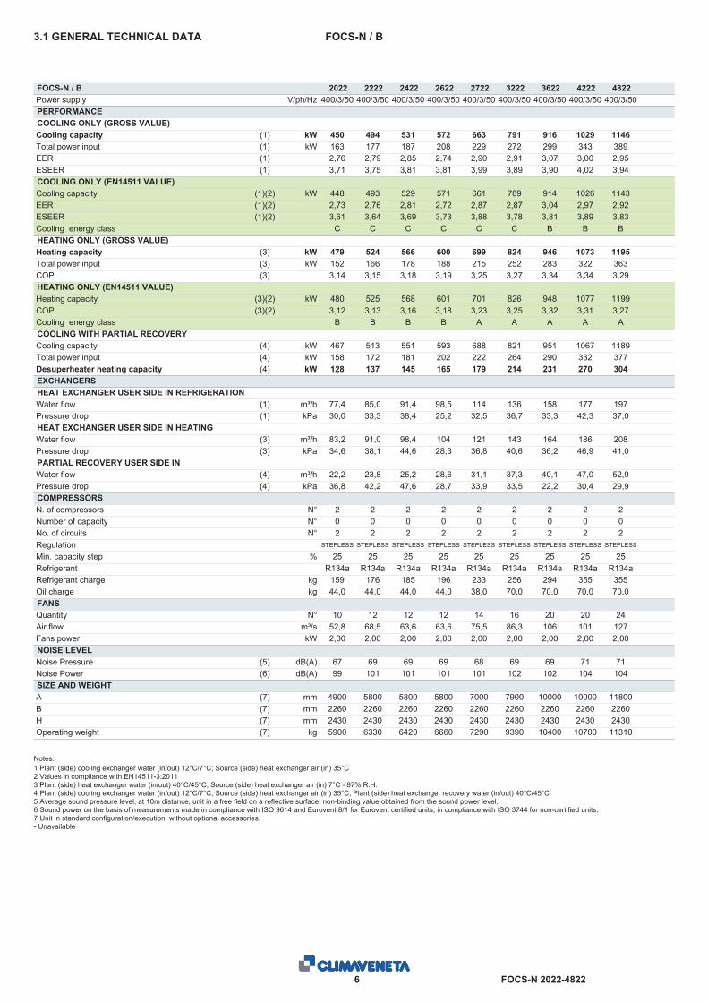
FOCS-N / B3.1 GENERAL TECHNICAL DATA
FOCS-N / B 2022 2222 2422 2622 2722 3222 3622 4222 4822Power supply V/ph/Hz 400/3/50 400/3/50 400/3/50 400/3/50 400/3/50 400/3/50 400/3/50 400/3/50 400/3/50PERFORMANCECOOLING ONLY (GROSS VALUE)Cooling capacity (1) kW 450 494 531 572 663 791 916 1029 1146Total power input (1) kW 163 177 187 208 229 272 299 343 389EER (1) 2,76 2,79 2,85 2,74 2,90 2,91 3,07 3,00 2,95ESEER (1) 3,71 3,75 3,81 3,81 3,99 3,89 3,90 4,02 3,94COOLING ONLY (EN14511 VALUE)Cooling capacity (1)(2) kW 448 493 529 571 661 789 914 1026 1143EER (1)(2) 2,73 2,76 2,81 2,72 2,87 2,87 3,04 2,97 2,92ESEER (1)(2) 3,61 3,64 3,69 3,73 3,88 3,78 3,81 3,89 3,83Cooling energy class C C C C C C B B BHEATING ONLY (GROSS VALUE)Heating capacity (3) kW 479 524 566 600 699 824 946 1073 1195Total power input (3) kW 152 166 178 188 215 252 283 322 363COP (3) 3,14 3,15 3,18 3,19 3,25 3,27 3,34 3,34 3,29HEATING ONLY (EN14511 VALUE)Heating capacity (3)(2) kW 480 525 568 601 701 826 948 1077 1199COP (3)(2) 3,12 3,13 3,16 3,18 3,23 3,25 3,32 3,31 3,27Cooling energy class B B B B A A A A ACOOLING WITH PARTIAL RECOVERYCooling capacity (4) kW 467 513 551 593 688 821 951 1067 1189Total power input (4) kW 158 172 181 202 222 264 290 332 377Desuperheater heating capacity (4) kW 128 137 145 165 179 214 231 270 304EXCHANGERSHEAT EXCHANGER USER SIDE IN REFRIGERATIONWater flow (1) m³/h 77,4 85,0 91,4 98,5 114 136 158 177 197Pressure drop (1) kPa 30,0 33,3 38,4 25,2 32,5 36,7 33,3 42,3 37,0HEAT EXCHANGER USER SIDE IN HEATINGWater flow (3) m³/h 83,2 91,0 98,4 104 121 143 164 186 208Pressure drop (3) kPa 34,6 38,1 44,6 28,3 36,8 40,6 36,2 46,9 41,0PARTIAL RECOVERY USER SIDE INREFRIGERATIONWater flow (4) m³/h 22,2 23,8 25,2 28,6 31,1 37,3 40,1 47,0 52,9Pressure drop (4) kPa 36,8 42,2 47,6 28,7 33,9 33,5 22,2 30,4 29,9COMPRESSORSN. of compressors N° 2 2 2 2 2 2 2 2 2Number of capacity N° 0 0 0 0 0 0 0 0 0No. of circuits N° 2 2 2 2 2 2 2 2 2Regulation STEPLESS STEPLESS STEPLESS STEPLESS STEPLESS STEPLESS STEPLESS STEPLESS STEPLESS
Min. capacity step % 25 25 25 25 25 25 25 25 25Refrigerant R134a R134a R134a R134a R134a R134a R134a R134a R134aRefrigerant charge kg 159 176 185 196 233 256 294 355 355Oil charge kg 44,0 44,0 44,0 44,0 38,0 70,0 70,0 70,0 70,0FANSQuantity N° 10 12 12 12 14 16 20 20 24Air flow m³/s 52,8 68,5 63,6 63,6 75,5 86,3 106 101 127Fans power kW 2,00 2,00 2,00 2,00 2,00 2,00 2,00 2,00 2,00NOISE LEVELNoise Pressure (5) dB(A) 67 69 69 69 68 69 69 71 71Noise Power (6) dB(A) 99 101 101 101 101 102 102 104 104SIZE AND WEIGHTA (7) mm 4900 5800 5800 5800 7000 7900 10000 10000 11800B (7) mm 2260 2260 2260 2260 2260 2260 2260 2260 2260H (7) mm 2430 2430 2430 2430 2430 2430 2430 2430 2430Operating weight (7) kg 5900 6330 6420 6660 7290 9390 10400 10700 11310
Notes:1 Plant (side) cooling exchanger water (in/out) 12°C/7°C; Source (side) heat exchanger air (in) 35°C2 Values in compliance with EN14511-3:20113 Plant (side) heat exchanger water (in/out) 40°C/45°C; Source (side) heat exchanger air (in) 7°C - 87% R.H.4 Plant (side) cooling exchanger water (in/out) 12°C/7°C; Source (side) heat exchanger air (in) 35°C; Plant (side) heat exchanger recovery water (in/out) 40°C/45°C5 Average sound pressure level, at 10m distance, unit in a free field on a reflective surface; non-binding value obtained from the sound power level.6 Sound power on the basis of measurements made in compliance with ISO 9614 and Eurovent 8/1 for Eurovent certified units; in compliance with ISO 3744 for non-certified units.7 Unit in standard configuration/execution, without optional accessories.- Unavailable
FOCS-N 2022-48227
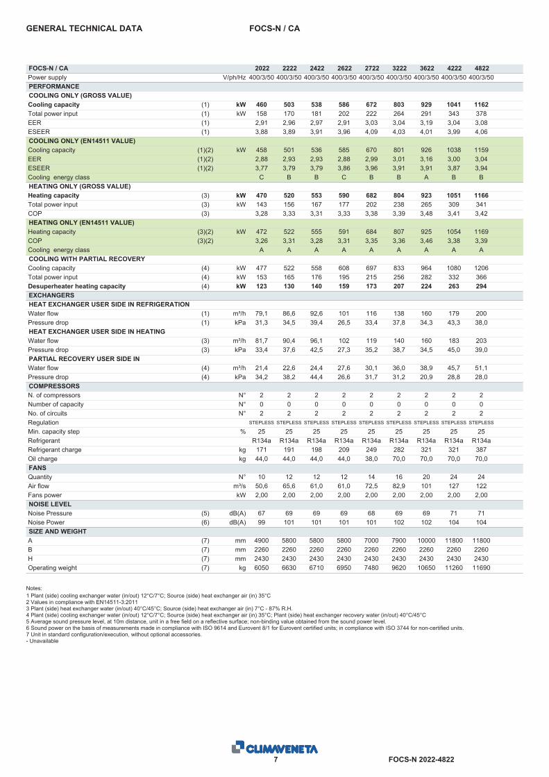
FOCS-N / CAGENERAL TECHNICAL DATA
FOCS-N / CA 2022 2222 2422 2622 2722 3222 3622 4222 4822Power supply V/ph/Hz 400/3/50 400/3/50 400/3/50 400/3/50 400/3/50 400/3/50 400/3/50 400/3/50 400/3/50PERFORMANCECOOLING ONLY (GROSS VALUE)Cooling capacity (1) kW 460 503 538 586 672 803 929 1041 1162Total power input (1) kW 158 170 181 202 222 264 291 343 378EER (1) 2,91 2,96 2,97 2,91 3,03 3,04 3,19 3,04 3,08ESEER (1) 3,88 3,89 3,91 3,96 4,09 4,03 4,01 3,99 4,06COOLING ONLY (EN14511 VALUE)Cooling capacity (1)(2) kW 458 501 536 585 670 801 926 1038 1159EER (1)(2) 2,88 2,93 2,93 2,88 2,99 3,01 3,16 3,00 3,04ESEER (1)(2) 3,77 3,79 3,79 3,86 3,96 3,91 3,91 3,87 3,94Cooling energy class C B B C B B A B BHEATING ONLY (GROSS VALUE)Heating capacity (3) kW 470 520 553 590 682 804 923 1051 1166Total power input (3) kW 143 156 167 177 202 238 265 309 341COP (3) 3,28 3,33 3,31 3,33 3,38 3,39 3,48 3,41 3,42HEATING ONLY (EN14511 VALUE)Heating capacity (3)(2) kW 472 522 555 591 684 807 925 1054 1169COP (3)(2) 3,26 3,31 3,28 3,31 3,35 3,36 3,46 3,38 3,39Cooling energy class A A A A A A A A ACOOLING WITH PARTIAL RECOVERYCooling capacity (4) kW 477 522 558 608 697 833 964 1080 1206Total power input (4) kW 153 165 176 195 215 256 282 332 366Desuperheater heating capacity (4) kW 123 130 140 159 173 207 224 263 294EXCHANGERSHEAT EXCHANGER USER SIDE IN REFRIGERATIONWater flow (1) m³/h 79,1 86,6 92,6 101 116 138 160 179 200Pressure drop (1) kPa 31,3 34,5 39,4 26,5 33,4 37,8 34,3 43,3 38,0HEAT EXCHANGER USER SIDE IN HEATINGWater flow (3) m³/h 81,7 90,4 96,1 102 119 140 160 183 203Pressure drop (3) kPa 33,4 37,6 42,5 27,3 35,2 38,7 34,5 45,0 39,0PARTIAL RECOVERY USER SIDE INREFRIGERATIONWater flow (4) m³/h 21,4 22,6 24,4 27,6 30,1 36,0 38,9 45,7 51,1Pressure drop (4) kPa 34,2 38,2 44,4 26,6 31,7 31,2 20,9 28,8 28,0COMPRESSORSN. of compressors N° 2 2 2 2 2 2 2 2 2Number of capacity N° 0 0 0 0 0 0 0 0 0No. of circuits N° 2 2 2 2 2 2 2 2 2Regulation STEPLESS STEPLESS STEPLESS STEPLESS STEPLESS STEPLESS STEPLESS STEPLESS STEPLESS
Min. capacity step % 25 25 25 25 25 25 25 25 25Refrigerant R134a R134a R134a R134a R134a R134a R134a R134a R134aRefrigerant charge kg 171 191 198 209 249 282 321 321 387Oil charge kg 44,0 44,0 44,0 44,0 38,0 70,0 70,0 70,0 70,0FANSQuantity N° 10 12 12 12 14 16 20 24 24Air flow m³/s 50,6 65,6 61,0 61,0 72,5 82,9 101 127 122Fans power kW 2,00 2,00 2,00 2,00 2,00 2,00 2,00 2,00 2,00NOISE LEVELNoise Pressure (5) dB(A) 67 69 69 69 68 69 69 71 71Noise Power (6) dB(A) 99 101 101 101 101 102 102 104 104SIZE AND WEIGHTA (7) mm 4900 5800 5800 5800 7000 7900 10000 11800 11800B (7) mm 2260 2260 2260 2260 2260 2260 2260 2260 2260H (7) mm 2430 2430 2430 2430 2430 2430 2430 2430 2430Operating weight (7) kg 6050 6630 6710 6950 7480 9620 10650 11260 11690
Notes:1 Plant (side) cooling exchanger water (in/out) 12°C/7°C; Source (side) heat exchanger air (in) 35°C2 Values in compliance with EN14511-3:20113 Plant (side) heat exchanger water (in/out) 40°C/45°C; Source (side) heat exchanger air (in) 7°C - 87% R.H.4 Plant (side) cooling exchanger water (in/out) 12°C/7°C; Source (side) heat exchanger air (in) 35°C; Plant (side) heat exchanger recovery water (in/out) 40°C/45°C5 Average sound pressure level, at 10m distance, unit in a free field on a reflective surface; non-binding value obtained from the sound power level.6 Sound power on the basis of measurements made in compliance with ISO 9614 and Eurovent 8/1 for Eurovent certified units; in compliance with ISO 3744 for non-certified units.7 Unit in standard configuration/execution, without optional accessories.- Unavailable
FOCS-N 2022-48228
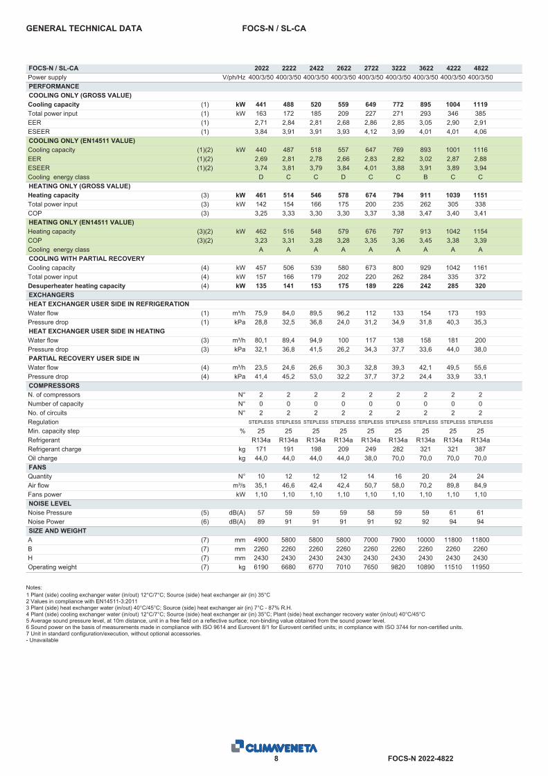
FOCS-N / SL-CAGENERAL TECHNICAL DATA
FOCS-N / SL-CA 2022 2222 2422 2622 2722 3222 3622 4222 4822Power supply V/ph/Hz 400/3/50 400/3/50 400/3/50 400/3/50 400/3/50 400/3/50 400/3/50 400/3/50 400/3/50PERFORMANCECOOLING ONLY (GROSS VALUE)Cooling capacity (1) kW 441 488 520 559 649 772 895 1004 1119Total power input (1) kW 163 172 185 209 227 271 293 346 385EER (1) 2,71 2,84 2,81 2,68 2,86 2,85 3,05 2,90 2,91ESEER (1) 3,84 3,91 3,91 3,93 4,12 3,99 4,01 4,01 4,06COOLING ONLY (EN14511 VALUE)Cooling capacity (1)(2) kW 440 487 518 557 647 769 893 1001 1116EER (1)(2) 2,69 2,81 2,78 2,66 2,83 2,82 3,02 2,87 2,88ESEER (1)(2) 3,74 3,81 3,79 3,84 4,01 3,88 3,91 3,89 3,94Cooling energy class D C C D C C B C CHEATING ONLY (GROSS VALUE)Heating capacity (3) kW 461 514 546 578 674 794 911 1039 1151Total power input (3) kW 142 154 166 175 200 235 262 305 338COP (3) 3,25 3,33 3,30 3,30 3,37 3,38 3,47 3,40 3,41HEATING ONLY (EN14511 VALUE)Heating capacity (3)(2) kW 462 516 548 579 676 797 913 1042 1154COP (3)(2) 3,23 3,31 3,28 3,28 3,35 3,36 3,45 3,38 3,39Cooling energy class A A A A A A A A ACOOLING WITH PARTIAL RECOVERYCooling capacity (4) kW 457 506 539 580 673 800 929 1042 1161Total power input (4) kW 157 166 179 202 220 262 284 335 372Desuperheater heating capacity (4) kW 135 141 153 175 189 226 242 285 320EXCHANGERSHEAT EXCHANGER USER SIDE IN REFRIGERATIONWater flow (1) m³/h 75,9 84,0 89,5 96,2 112 133 154 173 193Pressure drop (1) kPa 28,8 32,5 36,8 24,0 31,2 34,9 31,8 40,3 35,3HEAT EXCHANGER USER SIDE IN HEATINGWater flow (3) m³/h 80,1 89,4 94,9 100 117 138 158 181 200Pressure drop (3) kPa 32,1 36,8 41,5 26,2 34,3 37,7 33,6 44,0 38,0PARTIAL RECOVERY USER SIDE INREFRIGERATIONWater flow (4) m³/h 23,5 24,6 26,6 30,3 32,8 39,3 42,1 49,5 55,6Pressure drop (4) kPa 41,4 45,2 53,0 32,2 37,7 37,2 24,4 33,9 33,1COMPRESSORSN. of compressors N° 2 2 2 2 2 2 2 2 2Number of capacity N° 0 0 0 0 0 0 0 0 0No. of circuits N° 2 2 2 2 2 2 2 2 2Regulation STEPLESS STEPLESS STEPLESS STEPLESS STEPLESS STEPLESS STEPLESS STEPLESS STEPLESS
Min. capacity step % 25 25 25 25 25 25 25 25 25Refrigerant R134a R134a R134a R134a R134a R134a R134a R134a R134aRefrigerant charge kg 171 191 198 209 249 282 321 321 387Oil charge kg 44,0 44,0 44,0 44,0 38,0 70,0 70,0 70,0 70,0FANSQuantity N° 10 12 12 12 14 16 20 24 24Air flow m³/s 35,1 46,6 42,4 42,4 50,7 58,0 70,2 89,8 84,9Fans power kW 1,10 1,10 1,10 1,10 1,10 1,10 1,10 1,10 1,10NOISE LEVELNoise Pressure (5) dB(A) 57 59 59 59 58 59 59 61 61Noise Power (6) dB(A) 89 91 91 91 91 92 92 94 94SIZE AND WEIGHTA (7) mm 4900 5800 5800 5800 7000 7900 10000 11800 11800B (7) mm 2260 2260 2260 2260 2260 2260 2260 2260 2260H (7) mm 2430 2430 2430 2430 2430 2430 2430 2430 2430Operating weight (7) kg 6190 6680 6770 7010 7650 9820 10890 11510 11950
Notes:1 Plant (side) cooling exchanger water (in/out) 12°C/7°C; Source (side) heat exchanger air (in) 35°C2 Values in compliance with EN14511-3:20113 Plant (side) heat exchanger water (in/out) 40°C/45°C; Source (side) heat exchanger air (in) 7°C - 87% R.H.4 Plant (side) cooling exchanger water (in/out) 12°C/7°C; Source (side) heat exchanger air (in) 35°C; Plant (side) heat exchanger recovery water (in/out) 40°C/45°C5 Average sound pressure level, at 10m distance, unit in a free field on a reflective surface; non-binding value obtained from the sound power level.6 Sound power on the basis of measurements made in compliance with ISO 9614 and Eurovent 8/1 for Eurovent certified units; in compliance with ISO 3744 for non-certified units.7 Unit in standard configuration/execution, without optional accessories.- Unavailable

FOCS-N 2022-48229
FOCS-N / LN-CAGENERAL TECHNICAL DATA
FOCS-N / LN-CA 2022 2222 2422 2622 2722 3222 3622 4222 4822Power supply V/ph/Hz 400/3/50 400/3/50 400/3/50 400/3/50 400/3/50 400/3/50 400/3/50 400/3/50 400/3/50PERFORMANCECOOLING ONLY (GROSS VALUE)Cooling capacity (1) kW 444 492 524 564 654 780 904 1013 1130Total power input (1) kW 160 169 182 205 224 267 290 342 380EER (1) 2,78 2,91 2,87 2,75 2,92 2,92 3,11 2,96 2,97ESEER (1) 3,86 3,92 3,92 3,93 4,12 4,02 4,02 4,01 4,07COOLING ONLY (EN14511 VALUE)Cooling capacity (1)(2) kW 443 491 523 563 653 777 901 1010 1127EER (1)(2) 2,75 2,88 2,84 2,72 2,89 2,89 3,08 2,93 2,94ESEER (1)(2) 3,76 3,81 3,80 3,85 4,00 3,91 3,92 3,89 3,96Cooling energy class C C C C C C B B BHEATING ONLY (GROSS VALUE)Heating capacity (3) kW 467 520 553 586 682 804 923 1051 1166Total power input (3) kW 143 156 167 177 202 238 265 309 341COP (3) 3,26 3,33 3,31 3,30 3,38 3,39 3,48 3,41 3,42HEATING ONLY (EN14511 VALUE)Heating capacity (3)(2) kW 468 522 555 587 684 807 925 1054 1169COP (3)(2) 3,24 3,31 3,28 3,29 3,35 3,36 3,46 3,38 3,39Cooling energy class A A A A A A A A ACOOLING WITH PARTIAL RECOVERYCooling capacity (4) kW 461 510 544 585 679 809 937 1051 1173Total power input (4) kW 155 164 176 199 217 258 281 331 368Desuperheater heating capacity (4) kW 132 138 150 171 185 221 238 280 314EXCHANGERSHEAT EXCHANGER USER SIDE IN REFRIGERATIONWater flow (1) m³/h 76,5 84,7 90,2 97,1 113 134 156 174 195Pressure drop (1) kPa 29,3 33,0 37,5 24,5 31,7 35,7 32,4 41,1 36,0HEAT EXCHANGER USER SIDE IN HEATINGWater flow (3) m³/h 81,1 90,4 96,1 102 119 140 160 183 203Pressure drop (3) kPa 32,9 37,6 42,5 26,9 35,2 38,7 34,5 45,0 39,0PARTIAL RECOVERY USER SIDE INREFRIGERATIONWater flow (4) m³/h 23,0 24,0 26,1 29,6 32,1 38,5 41,3 48,6 54,5Pressure drop (4) kPa 39,5 43,2 50,8 30,7 36,1 35,6 23,5 32,6 31,8COMPRESSORSN. of compressors N° 2 2 2 2 2 2 2 2 2Number of capacity N° 0 0 0 0 0 0 0 0 0No. of circuits N° 2 2 2 2 2 2 2 2 2Regulation STEPLESS STEPLESS STEPLESS STEPLESS STEPLESS STEPLESS STEPLESS STEPLESS STEPLESS
Min. capacity step % 25 25 25 25 25 25 25 25 25Refrigerant R134a R134a R134a R134a R134a R134a R134a R134a R134aRefrigerant charge kg 171 191 198 209 249 282 321 321 387Oil charge kg 44,0 44,0 44,0 44,0 38,0 70,0 70,0 70,0 70,0FANSQuantity N° 10 12 12 12 14 16 20 24 24Air flow m³/s 38,1 50,6 46,0 46,0 54,9 62,8 76,1 97,0 92,1Fans power kW 1,20 1,20 1,20 1,20 1,20 1,20 1,20 1,20 1,20NOISE LEVELNoise Pressure (5) dB(A) 61 63 63 63 62 63 63 65 65Noise Power (6) dB(A) 93 95 95 95 95 96 96 98 98SIZE AND WEIGHTA (7) mm 4900 5800 5800 5800 7000 7900 10000 11800 11800B (7) mm 2260 2260 2260 2260 2260 2260 2260 2260 2260H (7) mm 2430 2430 2430 2430 2430 2430 2430 2430 2430Operating weight (7) kg 6120 6610 6700 6930 7580 9730 10800 11400 11860
Notes:1 Plant (side) cooling exchanger water (in/out) 12°C/7°C; Source (side) heat exchanger air (in) 35°C2 Values in compliance with EN14511-3:20113 Plant (side) heat exchanger water (in/out) 40°C/45°C; Source (side) heat exchanger air (in) 7°C - 87% R.H.4 Plant (side) cooling exchanger water (in/out) 12°C/7°C; Source (side) heat exchanger air (in) 35°C; Plant (side) heat exchanger recovery water (in/out) 40°C/45°C5 Average sound pressure level, at 10m distance, unit in a free field on a reflective surface; non-binding value obtained from the sound power level.6 Sound power on the basis of measurements made in compliance with ISO 9614 and Eurovent 8/1 for Eurovent certified units; in compliance with ISO 3744 for non-certified units.7 Unit in standard configuration/execution, without optional accessories.- Unavailable
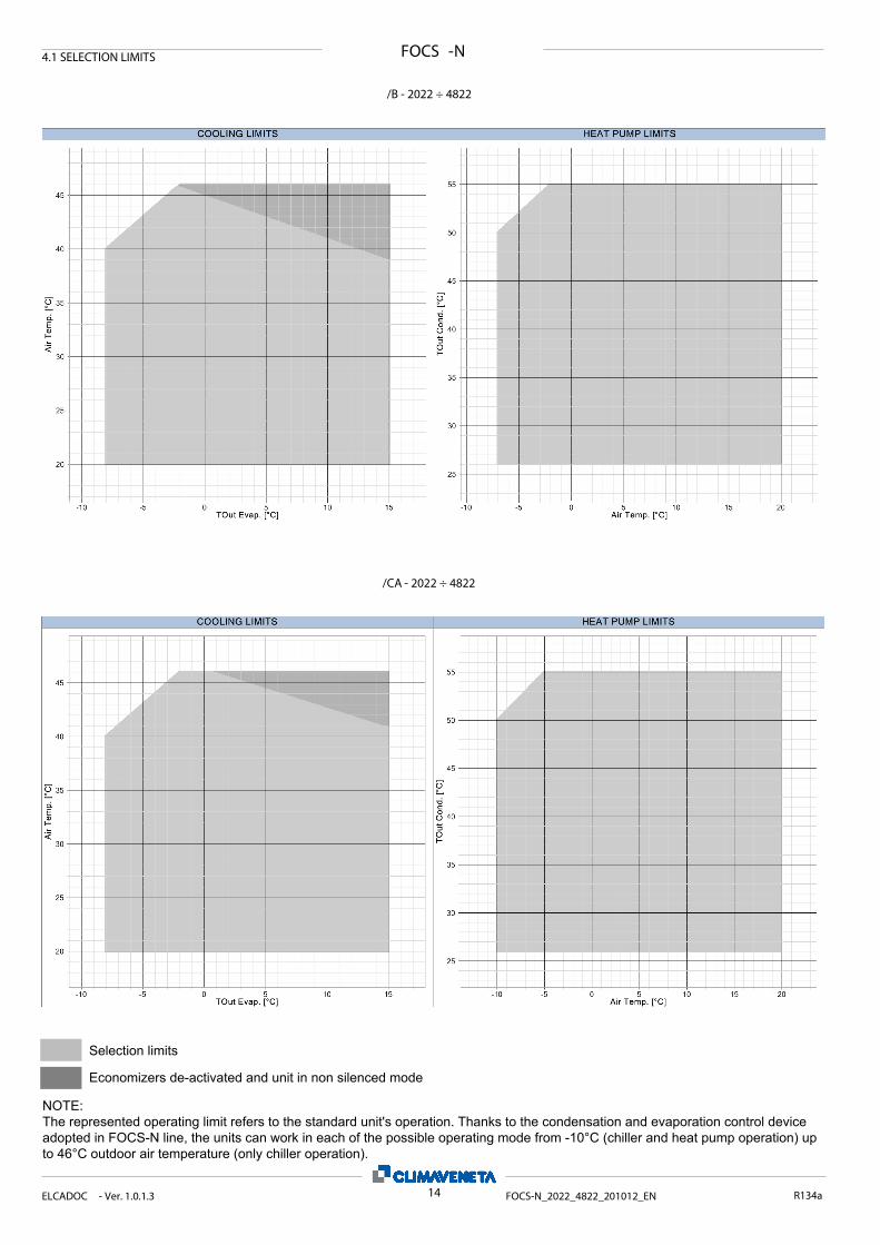
FOCS -N4.1 SELECTION LIMITS
/B - 2022 ÷ 4822
/CA - 2022 ÷ 4822
14ELCADOC - Ver. 1.0.1.3 FOCS-N_2022_4822_201012_EN R134a
Economizers de-activated and unit in non silenced mode
Selection limits
NOTE: The represented operating limit refers to the standard unit's operation. Thanks to the condensation and evaporation control device adopted in FOCS-N line, the units can work in each of the possible operating mode from -10°C (chiller and heat pump operation) up to 46°C outdoor air temperature (only chiller operation).
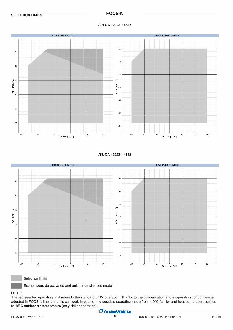
FOCS-NSELECTION LIMITS
/LN-CA - 2022 ÷ 4822
/SL-CA - 2022 ÷ 4822
15ELCADOC - Ver. 1.0.1.3 FOCS-N_2022_4822_201012_EN R134a
Economizers de-activated and unit in non silenced mode
Selection limits
NOTE: The represented operating limit refers to the standard unit's operation. Thanks to the condensation and evaporation control device adopted in FOCS-N line, the units can work in each of the possible operating mode from -10°C (chiller and heat pump operation) up to 46°C outdoor air temperature (only chiller operation).
FOCS-NSELECTION LIMITS
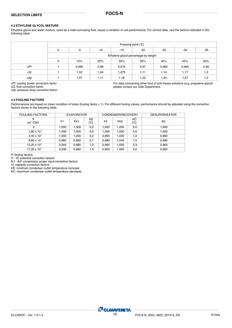
4.2 ETHYLENE GLYCOL MIXTUREEthylene glycol and water mixture, used as a heat-conveying fluid, cause a variation in unit performance. For correct data, use the factors indicated in the following tabel.
0 -5 -10 -15 -20 -25 -30 -35
50%45%40%35%30%20%12%0
0,960,9640,9650,970,9740,980,9851
1,21,171,141,111,0751,041,021
1,31,271,241,221,181,111,071cdp
cQ
cPf
cdp: pressure drop correction factorcQ: flow correction factorcPf: cooling power correction factor For data concerning other kind of anti-freeze solutions (e,g, propylene glycol)
please contact our Sale Department.
Freezing point (°C)
Ethylene glycol percentage by weight
4.3 FOULING FACTORSPerformances are based on clean condition of tubes (fouling factor = 1). For different fouling values, performance should be adjusted using the correction factors shown in the following table.
FOULING FACTORS EVAPORATOR CONDENSER/RECOVERY DESUPERHEATER
KE[°C] R3
KC[°C]FK2F2FK1F1
ff(m °CW)2
1,000 1,000 0,0 1,000 1,000 0,0 1,0000
1,000 1,000 0,0 1,000 1,000 0,0 1,0001,80 x 10-5
1,000 1,000 0,0 0,990 1,030 1,0 0,9904,40 x 10-5
0,960 0,990 0,7 0,980 1,040 1,5 0,9808,80 x 10-5
0,944 0,985 1,0 0,964 1,050 2,3 0,96413,20 x 10-5
0,930 0,980 1,5 0,950 1,060 3,0 0,95017,20 x 10-5
ff: fouling factorsf1 - f2: potential correction factorsfk1 - fk2: compressor power input correction factorsr3: capacity correction factorsKE: minimum condenser outlet temperature increaseKC: maximum condenser outlet temperature decrease
16ELCADOC - Ver. 1.0.1.3 FOCS-N_2022_4822_201012_EN R134a
FOCS-N
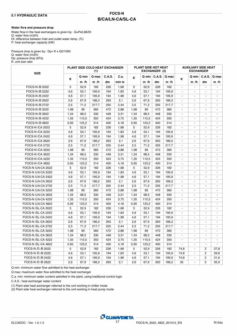
B/CA/LN-CA/SL-CA5.1 HYDRAULIC DATA
Water flow and pressure dropWater flow in the heat exchangers is given by: Q=Px0,86/Dt Q: water flow (m3/h) Dt: difference between inlet and outlet water temp. (°C) P: heat exchanger capacity (kW)
Pressure drop is given by: Dp= K x Q2/1000Q: water flow (m3/h)Dp: pressure drop (kPa)K: unit size ratio
AUXILIARY SIDE HEAT EXCHANGER
Q max
m³/h
Q min
m³/hK
PLANT SIDE HOT HEAT EXCHANGER (2)
Q max
m³/h
Q min
m³/hK
SIZE
PLANT SIDE COLD HEAT EXCHANGER
C.a.
min m³Q max
m³/h
Q min
m³/hK
C.A.S.
dm³C.A.S.
dm³C.A.S.
dm³5 52,9 182 1,68 5 52,9 182 - - -FOCS-N /B 2022 226 226 -
4,6 53,1 195,9 1,83 4,6 53,1 195,9 - - -FOCS-N /B 2222 194 194 -4,6 57,1 195,9 1,98 4,6 57,1 195,9 - - -FOCS-N /B 2422 194 194 -2,6 67,9 186,2 2,1 2,6 67,9 186,2 - - -FOCS-N /B 2622 263 263 -2,5 71,2 217,7 2,44 2,5 71,2 217,7 - - -FOCS-N /B 2722 255 255 -1,98 85 360 2,88 1,98 85 360 - - -FOCS-N /B 3222 472 472 -1,34 98,5 330 3,31 1,34 98,5 330 - - -FOCS-N /B 3622 448 448 -1,35 110,5 350 3,75 1,35 110,5 350 - - -FOCS-N /B 4222 424 424 -0,95 123,2 314 4,18 0,95 123,2 314 - - -FOCS-N /B 4822 400 400 -
5 52,9 182 1,68 5 52,9 182 - - -FOCS-N /CA 2022 226 226 -4,6 53,1 195,9 1,83 4,6 53,1 195,9 - - -FOCS-N /CA 2222 194 194 -4,6 57,1 195,9 1,98 4,6 57,1 195,9 - - -FOCS-N /CA 2422 194 194 -2,6 67,9 186,2 2,1 2,6 67,9 186,2 - - -FOCS-N /CA 2622 263 263 -2,5 71,2 217,7 2,44 2,5 71,2 217,7 - - -FOCS-N /CA 2722 255 255 -1,98 85 360 2,88 1,98 85 360 - - -FOCS-N /CA 3222 472 472 -1,34 98,5 330 3,31 1,34 98,5 330 - - -FOCS-N /CA 3622 448 448 -1,35 110,5 350 3,75 1,35 110,5 350 - - -FOCS-N /CA 4222 424 424 -0,95 123,2 314 4,18 0,95 123,2 314 - - -FOCS-N /CA 4822 400 400 -
5 52,9 182 1,68 5 52,9 182 - - -FOCS-N /LN-CA 2022 226 226 -4,6 53,1 195,9 1,83 4,6 53,1 195,9 - - -FOCS-N /LN-CA 2222 194 194 -4,6 57,1 195,9 1,98 4,6 57,1 195,9 - - -FOCS-N /LN-CA 2422 194 194 -2,6 67,9 186,2 2,1 2,6 67,9 186,2 - - -FOCS-N /LN-CA 2622 263 263 -2,5 71,2 217,7 2,44 2,5 71,2 217,7 - - -FOCS-N /LN-CA 2722 255 255 -1,98 85 360 2,88 1,98 85 360 - - -FOCS-N /LN-CA 3222 472 472 -1,34 98,5 330 3,31 1,34 98,5 330 - - -FOCS-N /LN-CA 3622 448 448 -1,35 110,5 350 3,75 1,35 110,5 350 - - -FOCS-N /LN-CA 4222 424 424 -0,95 123,2 314 4,18 0,95 123,2 314 - - -FOCS-N /LN-CA 4822 400 400 -
5 52,9 182 1,68 5 52,9 182 - - -FOCS-N /SL-CA 2022 226 226 -4,6 53,1 195,9 1,83 4,6 53,1 195,9 - - -FOCS-N /SL-CA 2222 194 194 -4,6 57,1 195,9 1,98 4,6 57,1 195,9 - - -FOCS-N /SL-CA 2422 194 194 -2,6 67,9 186,2 2,1 2,6 67,9 186,2 - - -FOCS-N /SL-CA 2622 263 263 -2,5 71,2 217,7 2,44 2,5 71,2 217,7 - - -FOCS-N /SL-CA 2722 255 255 -1,98 85 360 2,88 1,98 85 360 - - -FOCS-N /SL-CA 3222 472 472 -1,34 98,5 330 3,31 1,34 98,5 330 - - -FOCS-N /SL-CA 3622 448 448 -1,35 110,5 350 3,75 1,35 110,5 350 - - -FOCS-N /SL-CA 4222 424 424 -0,95 123,2 314 4,18 0,95 123,2 314 - - -FOCS-N /SL-CA 4822 400 400 -
5 52,9 182 1,68 5 52,9 182 74,8 - 27,8FOCS-N /D /B 2022 226 226 24,6 53,1 195,9 1,83 4,6 53,1 195,9 74,8 - 29,8FOCS-N /D /B 2222 194 194 24,6 57,1 195,9 1,98 4,6 57,1 195,9 74,8 - 31,6FOCS-N /D /B 2422 194 194 22,6 67,9 186,2 2,1 2,6 67,9 186,2 35 - 35,9FOCS-N /D /B 2622 263 263 3
Q min: minimum water flow admitted to the heat exchangerQ max: maximum water flow admitted to the heat exchanger
C.a. min: minimum water content admitted in the plant, using traditional control logic
C.A.S.: heat exchanger water content
(1) Plant side heat exchanger referred to the unit working in chiller mode (2) Plant side heat exchanger referred to the unit working in heat pump mode
17ELCADOC - Ver. 1.0.1.3 FOCS-N_2022_4822_201012_EN R134a
(1)
FOCS-N
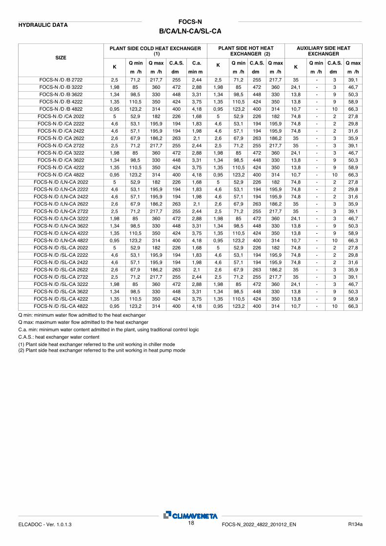
B/CA/LN-CA/SL-CAHYDRAULIC DATA
AUXILIARY SIDE HEAT EXCHANGER
Q max
m³/h
Q min
m³/hK
PLANT SIDE HOT HEAT EXCHANGER (2)
Q max
m³/h
Q min
m³/hK
SIZE
PLANT SIDE COLD HEAT EXCHANGER
C.a.
min m³Q max
m³/h
Q min
m³/hK
C.A.S.
dm³C.A.S.
dm³C.A.S.
dm³2,5 71,2 217,7 2,44 2,5 71,2 217,7 35 - 39,1FOCS-N /D /B 2722 255 255 31,98 85 360 2,88 1,98 85 360 24,1 - 46,7FOCS-N /D /B 3222 472 472 31,34 98,5 330 3,31 1,34 98,5 330 13,8 - 50,3FOCS-N /D /B 3622 448 448 91,35 110,5 350 3,75 1,35 110,5 350 13,8 - 58,9FOCS-N /D /B 4222 424 424 90,95 123,2 314 4,18 0,95 123,2 314 10,7 - 66,3FOCS-N /D /B 4822 400 400 10
5 52,9 182 1,68 5 52,9 182 74,8 - 27,8FOCS-N /D /CA 2022 226 226 24,6 53,1 195,9 1,83 4,6 53,1 195,9 74,8 - 29,8FOCS-N /D /CA 2222 194 194 24,6 57,1 195,9 1,98 4,6 57,1 195,9 74,8 - 31,6FOCS-N /D /CA 2422 194 194 22,6 67,9 186,2 2,1 2,6 67,9 186,2 35 - 35,9FOCS-N /D /CA 2622 263 263 32,5 71,2 217,7 2,44 2,5 71,2 217,7 35 - 39,1FOCS-N /D /CA 2722 255 255 31,98 85 360 2,88 1,98 85 360 24,1 - 46,7FOCS-N /D /CA 3222 472 472 31,34 98,5 330 3,31 1,34 98,5 330 13,8 - 50,3FOCS-N /D /CA 3622 448 448 91,35 110,5 350 3,75 1,35 110,5 350 13,8 - 58,9FOCS-N /D /CA 4222 424 424 90,95 123,2 314 4,18 0,95 123,2 314 10,7 - 66,3FOCS-N /D /CA 4822 400 400 10
5 52,9 182 1,68 5 52,9 182 74,8 - 27,8FOCS-N /D /LN-CA 2022 226 226 24,6 53,1 195,9 1,83 4,6 53,1 195,9 74,8 - 29,8FOCS-N /D /LN-CA 2222 194 194 24,6 57,1 195,9 1,98 4,6 57,1 195,9 74,8 - 31,6FOCS-N /D /LN-CA 2422 194 194 22,6 67,9 186,2 2,1 2,6 67,9 186,2 35 - 35,9FOCS-N /D /LN-CA 2622 263 263 32,5 71,2 217,7 2,44 2,5 71,2 217,7 35 - 39,1FOCS-N /D /LN-CA 2722 255 255 31,98 85 360 2,88 1,98 85 360 24,1 - 46,7FOCS-N /D /LN-CA 3222 472 472 31,34 98,5 330 3,31 1,34 98,5 330 13,8 - 50,3FOCS-N /D /LN-CA 3622 448 448 91,35 110,5 350 3,75 1,35 110,5 350 13,8 - 58,9FOCS-N /D /LN-CA 4222 424 424 90,95 123,2 314 4,18 0,95 123,2 314 10,7 - 66,3FOCS-N /D /LN-CA 4822 400 400 10
5 52,9 182 1,68 5 52,9 182 74,8 - 27,8FOCS-N /D /SL-CA 2022 226 226 24,6 53,1 195,9 1,83 4,6 53,1 195,9 74,8 - 29,8FOCS-N /D /SL-CA 2222 194 194 24,6 57,1 195,9 1,98 4,6 57,1 195,9 74,8 - 31,6FOCS-N /D /SL-CA 2422 194 194 22,6 67,9 186,2 2,1 2,6 67,9 186,2 35 - 35,9FOCS-N /D /SL-CA 2622 263 263 32,5 71,2 217,7 2,44 2,5 71,2 217,7 35 - 39,1FOCS-N /D /SL-CA 2722 255 255 31,98 85 360 2,88 1,98 85 360 24,1 - 46,7FOCS-N /D /SL-CA 3222 472 472 31,34 98,5 330 3,31 1,34 98,5 330 13,8 - 50,3FOCS-N /D /SL-CA 3622 448 448 91,35 110,5 350 3,75 1,35 110,5 350 13,8 - 58,9FOCS-N /D /SL-CA 4222 424 424 90,95 123,2 314 4,18 0,95 123,2 314 10,7 - 66,3FOCS-N /D /SL-CA 4822 400 400 10
Q min: minimum water flow admitted to the heat exchangerQ max: maximum water flow admitted to the heat exchanger
C.a. min: minimum water content admitted in the plant, using traditional control logic
C.A.S.: heat exchanger water content
(1) Plant side heat exchanger referred to the unit working in chiller mode (2) Plant side heat exchanger referred to the unit working in heat pump mode
18ELCADOC - Ver. 1.0.1.3 FOCS-N_2022_4822_201012_EN R134a
(1)
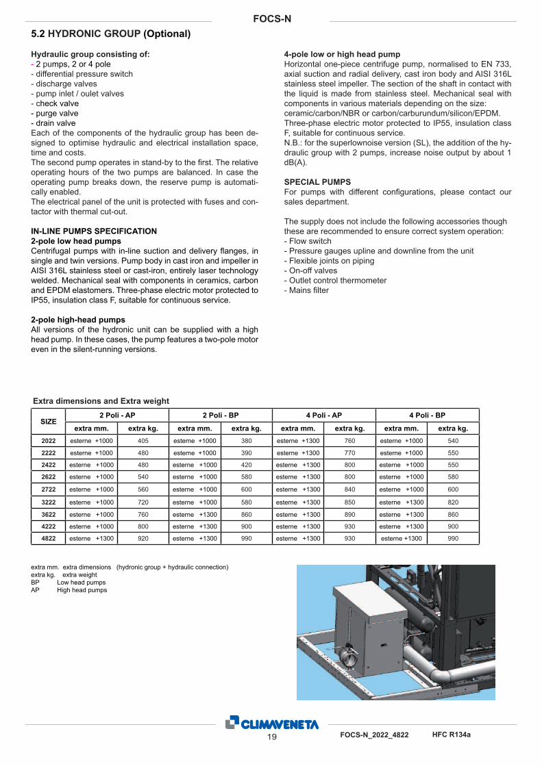
5.2 HYDRONIC GROUP (Optional)
extra mm. extra dimensions (hydronic group + hydraulic connection)
extra kg. extra weight
BP Low head pumps
AP High head pumps
Hydraulic group consisting of:
- 2 pumps, 2 or 4 pole
- differential pressure switch
- discharge valves
- pump inlet / oulet valves
- check valve
- purge valve
- drain valve
Each of the components of the hydraulic group has been de-
signed to optimise hydraulic and electrical installation space,
time and costs.
The second pump operates in stand-by to the fi rst. The relative
operating hours of the two pumps are balanced. In case the
operating pump breaks down, the reserve pump is automati-
cally enabled.
The electrical panel of the unit is protected with fuses and con-
tactor with thermal cut-out.
IN-LINE PUMPS SPECIFICATION
2-pole low head pumps
Centrifugal pumps with in-line suction and delivery fl anges, in
single and twin versions. Pump body in cast iron and impeller in
AISI 316L stainless steel or cast-iron, entirely laser technology
welded. Mechanical seal with components in ceramics, carbon
and EPDM elastomers. Three-phase electric motor protected to
IP55, insulation class F, suitable for continuous service.
2-pole high-head pumps
All versions of the hydronic unit can be supplied with a high
head pump. In these cases, the pump features a two-pole motor
even in the silent-running versions.
4-pole low or high head pump
Horizontal one-piece centrifuge pump, normalised to EN 733,
axial suction and radial delivery, cast iron body and AISI 316L
stainless steel impeller. The section of the shaft in contact with
the liquid is made from stainless steel. Mechanical seal with
components in various materials depending on the size:
ceramic/carbon/NBR or carbon/carburundum/silicon/EPDM.
Three-phase electric motor protected to IP55, insulation class
F, suitable for continuous service.
N.B.: for the superlownoise version (SL), the addition of the hy-
draulic group with 2 pumps, increase noise output by about 1
dB(A).
SPECIAL PUMPS
For pumps with different confi gurations, please contact our
sales department.
The supply does not include the following accessories though
these are recommended to ensure correct system operation:
- Flow switch
- Pressure gauges upline and downline from the unit
- Flexible joints on piping
- On-off valves
- Outlet control thermometer
- Mains fi lter
SIZE2 Poli - AP 2 Poli - BP 4 Poli - AP 4 Poli - BP
extra mm. extra kg. extra mm. extra kg. extra mm. extra kg. extra mm. extra kg.
2022 esterne +1000 405 esterne +1000 380 esterne +1300 760 esterne +1000 540
2222 esterne +1000 480 esterne +1000 390 esterne +1300 770 esterne +1000 550
2422 esterne +1000 480 esterne +1000 420 esterne +1300 800 esterne +1000 550
2622 esterne +1000 540 esterne +1000 580 esterne +1300 800 esterne +1000 580
2722 esterne +1000 560 esterne +1000 600 esterne +1300 840 esterne +1000 600
3222 esterne +1000 720 esterne +1000 580 esterne +1300 850 esterne +1300 820
3622 esterne +1000 760 esterne +1300 860 esterne +1300 890 esterne +1300 860
4222 esterne +1000 800 esterne +1300 900 esterne +1300 930 esterne +1300 900
4822 esterne +1300 920 esterne +1300 990 esterne +1300 930 esterne +1300 990
Extra dimensions and Extra weight
19 FOCS-N_2022_4822 HFC R134a
FOCS-N
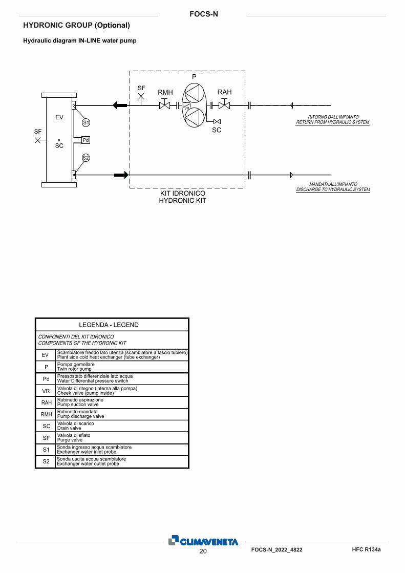
HYDRONIC GROUP (Optional)
Hydraulic diagram IN-LINE water pump
Sonda ingresso acqua scambiatore Exchanger water inlet probe
LEGENDA - LEGEND
SC
S1
S2Sonda uscita acqua scambiatoreExchanger water outlet probe
EV
Drain valveValvola di scarico
Plant side cold heat exchanger (tube exchanger)Scambiatore freddo lato utenza (scambiatore a fascio tubiero)
RITORNO DALL'IMPIANTORETURN FROM HYDRAULIC SYSTEM
MANDATA ALL'IMPIANTODISCHARGE TO HYDRAULIC SYSTEM
SF Purge valveValvola di sfiato
S1
S2
EV
SF
SC
CONPONENTI DEL KIT IDRONICOCOMPONENTS OF THE HYDRONIC KIT
Pd
P
VR
SC
RAHRMHSF
KIT IDRONICOHYDRONIC KIT
RAH Pump suction valveRubinetto aspirazione
RMH Pump discharge valveRubinetto mandata
VRValvola di ritegno (interna alla pompa)Cheek valve (pump inside)
PPompa gemellareTwin rotor pump
Pd Water Differential pressure switchPressostato differenziale lato acqua
20 FOCS-N_2022_4822
FOCS-N
HFC R134a
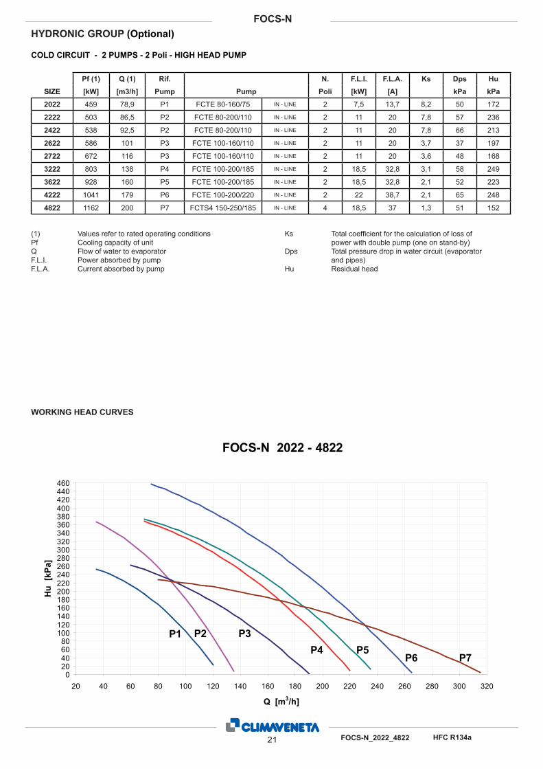
Pf (1) Q (1) Rif. N. F.L.I. F.L.A. Ks Dps Hu
SIZE [kW] [m3/h] Pump Pump Poli [kW] [A] kPa kPa
2022 459 78,9 P1 FCTE 80-160/75 IN - LINE 2 7,5 13,7 8,2 50 172
2222 503 86,5 P2 FCTE 80-200/110 IN - LINE 2 11 20 7,8 57 236
2422 538 92,5 P2 FCTE 80-200/110 IN - LINE 2 11 20 7,8 66 213
2622 586 101 P3 FCTE 100-160/110 IN - LINE 2 11 20 3,7 37 197
2722 672 116 P3 FCTE 100-160/110 IN - LINE 2 11 20 3,6 48 168
3222 803 138 P4 FCTE 100-200/185 IN - LINE 2 18,5 32,8 3,1 58 249
3622 928 160 P5 FCTE 100-200/185 IN - LINE 2 18,5 32,8 2,1 52 223
4222 1041 179 P6 FCTE 100-200/220 IN - LINE 2 22 38,7 2,1 65 248
4822 1162 200 P7 FCTS4 150-250/185 IN - LINE 4 18,5 37 1,3 51 152
COLD CIRCUIT - 2 PUMPS - 2 Poli - HIGH HEAD PUMP
(1) Values refer to rated operating conditions
Pf Cooling capacity of unit
Q Flow of water to evaporator
F.L.I. Power absorbed by pump
F.L.A. Current absorbed by pump
Ks Total coeffi cient for the calculation of loss of
power with double pump (one on stand-by)
Dps Total pressure drop in water circuit (evaporator
and pipes)
Hu Residual head
HYDRONIC GROUP (Optional)
WORKING HEAD CURVES
FOCS-N 2022 - 4822
0
20
40
60
80
100
120
140
160
180
200
220
240
260
280
300
320
340
360
380
400
420
440
460
20 40 60 80 100 120 140 160 180 200 220 240 260 280 300 320
Q [m3/h]
Hu
[k
Pa]
P1 P2 P3
P4 P5P6 P7
21 FOCS-N_2022_4822 HFC R134a
FOCS-N
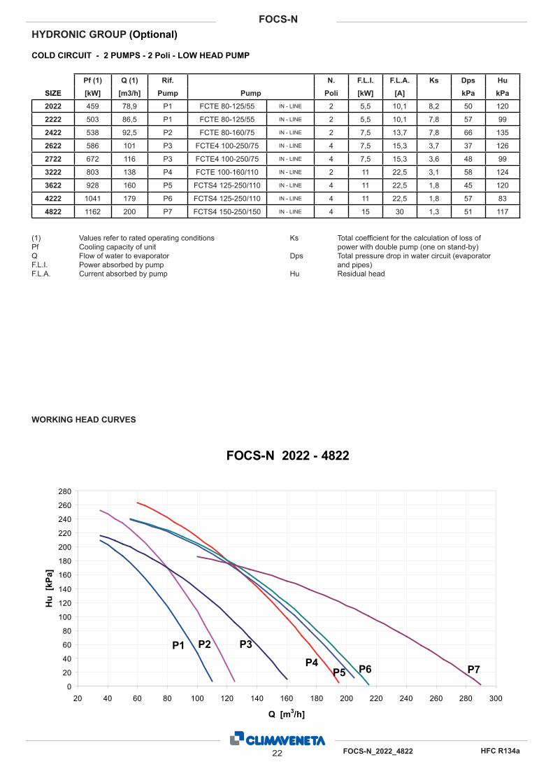
HYDRONIC GROUP (Optional)
Pf (1) Q (1) Rif. N. F.L.I. F.L.A. Ks Dps Hu
SIZE [kW] [m3/h] Pump Pump Poli [kW] [A] kPa kPa
2022 459 78,9 P1 FCTE 80-125/55 IN - LINE 2 5,5 10,1 8,2 50 120
2222 503 86,5 P1 FCTE 80-125/55 IN - LINE 2 5,5 10,1 7,8 57 99
2422 538 92,5 P2 FCTE 80-160/75 IN - LINE 2 7,5 13,7 7,8 66 135
2622 586 101 P3 FCTE4 100-250/75 IN - LINE 4 7,5 15,3 3,7 37 126
2722 672 116 P3 FCTE4 100-250/75 IN - LINE 4 7,5 15,3 3,6 48 99
3222 803 138 P4 FCTE 100-160/110 IN - LINE 2 11 22,5 3,1 58 124
3622 928 160 P5 FCTS4 125-250/110 IN - LINE 4 11 22,5 1,8 45 120
4222 1041 179 P6 FCTS4 125-250/110 IN - LINE 4 11 22,5 1,8 57 83
4822 1162 200 P7 FCTS4 150-250/150 IN - LINE 4 15 30 1,3 51 117
COLD CIRCUIT - 2 PUMPS - 2 Poli - LOW HEAD PUMP
(1) Values refer to rated operating conditions
Pf Cooling capacity of unit
Q Flow of water to evaporator
F.L.I. Power absorbed by pump
F.L.A. Current absorbed by pump
Ks Total coeffi cient for the calculation of loss of
power with double pump (one on stand-by)
Dps Total pressure drop in water circuit (evaporator
and pipes)
Hu Residual head
WORKING HEAD CURVES
FOCS-N 2022 - 4822
0
20
40
60
80
100
120
140
160
180
200
220
240
260
280
20 40 60 80 100 120 140 160 180 200 220 240 260 280 300
Q [m3/h]
Hu
[k
Pa]
P1 P2 P3
P4P5 P6 P7
22 FOCS-N_2022_4822
FOCS-N
HFC R134a
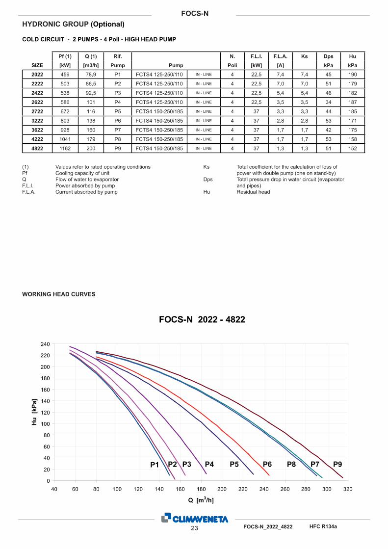
HYDRONIC GROUP (Optional)
Pf (1) Q (1) Rif. N. F.L.I. F.L.A. Ks Dps Hu
SIZE [kW] [m3/h] Pump Pump Poli [kW] [A] kPa kPa
2022 459 78,9 P1 FCTS4 125-250/110 IN - LINE 4 22,5 7,4 7,4 45 190
2222 503 86,5 P2 FCTS4 125-250/110 IN - LINE 4 22,5 7,0 7,0 51 179
2422 538 92,5 P3 FCTS4 125-250/110 IN - LINE 4 22,5 5,4 5,4 46 182
2622 586 101 P4 FCTS4 125-250/110 IN - LINE 4 22,5 3,5 3,5 34 187
2722 672 116 P5 FCTS4 150-250/185 IN - LINE 4 37 3,3 3,3 44 185
3222 803 138 P6 FCTS4 150-250/185 IN - LINE 4 37 2,8 2,8 53 171
3622 928 160 P7 FCTS4 150-250/185 IN - LINE 4 37 1,7 1,7 42 175
4222 1041 179 P8 FCTS4 150-250/185 IN - LINE 4 37 1,7 1,7 53 158
4822 1162 200 P9 FCTS4 150-250/185 IN - LINE 4 37 1,3 1,3 51 152
COLD CIRCUIT - 2 PUMPS - 4 Poli - HIGH HEAD PUMP
(1) Values refer to rated operating conditions
Pf Cooling capacity of unit
Q Flow of water to evaporator
F.L.I. Power absorbed by pump
F.L.A. Current absorbed by pump
Ks Total coeffi cient for the calculation of loss of
power with double pump (one on stand-by)
Dps Total pressure drop in water circuit (evaporator
and pipes)
Hu Residual head
WORKING HEAD CURVES
FOCS-N 2022 - 4822
0
20
40
60
80
100
120
140
160
180
200
220
240
40 60 80 100 120 140 160 180 200 220 240 260 280 300 320
Q [m3/h]
Hu
[k
Pa]
P1 P2 P3 P4 P5 P6 P7P8 P9
23 FOCS-N_2022_4822 HFC R134a
FOCS-N
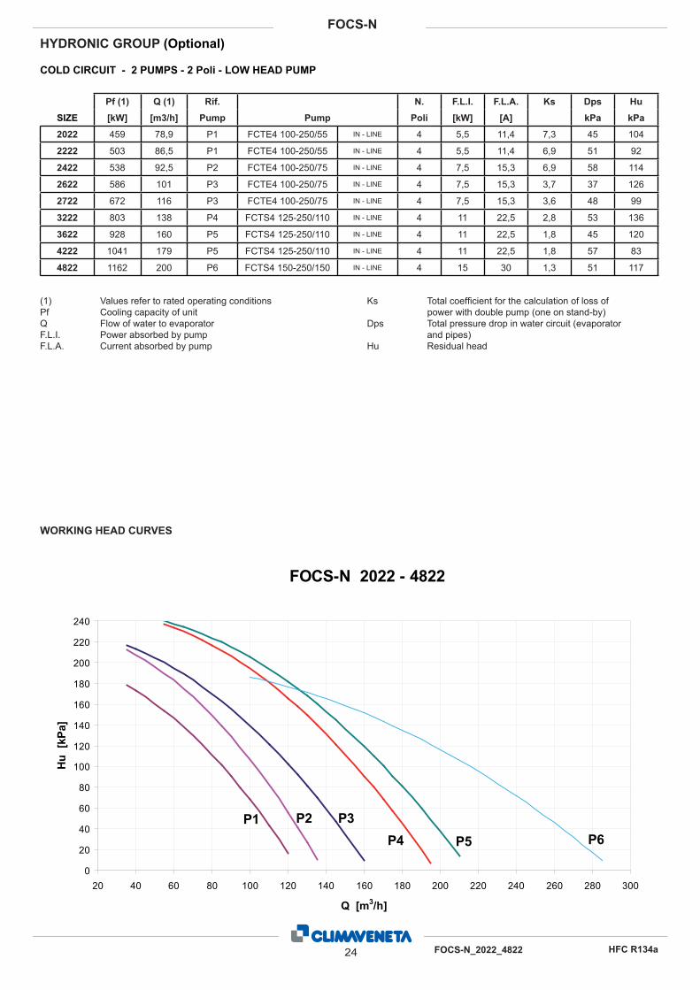
HYDRONIC GROUP (Optional)
Pf (1) Q (1) Rif. N. F.L.I. F.L.A. Ks Dps Hu
SIZE [kW] [m3/h] Pump Pump Poli [kW] [A] kPa kPa
2022 459 78,9 P1 FCTE4 100-250/55 IN - LINE 4 5,5 11,4 7,3 45 104
2222 503 86,5 P1 FCTE4 100-250/55 IN - LINE 4 5,5 11,4 6,9 51 92
2422 538 92,5 P2 FCTE4 100-250/75 IN - LINE 4 7,5 15,3 6,9 58 114
2622 586 101 P3 FCTE4 100-250/75 IN - LINE 4 7,5 15,3 3,7 37 126
2722 672 116 P3 FCTE4 100-250/75 IN - LINE 4 7,5 15,3 3,6 48 99
3222 803 138 P4 FCTS4 125-250/110 IN - LINE 4 11 22,5 2,8 53 136
3622 928 160 P5 FCTS4 125-250/110 IN - LINE 4 11 22,5 1,8 45 120
4222 1041 179 P5 FCTS4 125-250/110 IN - LINE 4 11 22,5 1,8 57 83
4822 1162 200 P6 FCTS4 150-250/150 IN - LINE 4 15 30 1,3 51 117
COLD CIRCUIT - 2 PUMPS - 2 Poli - LOW HEAD PUMP
(1) Values refer to rated operating conditions
Pf Cooling capacity of unit
Q Flow of water to evaporator
F.L.I. Power absorbed by pump
F.L.A. Current absorbed by pump
Ks Total coeffi cient for the calculation of loss of
power with double pump (one on stand-by)
Dps Total pressure drop in water circuit (evaporator
and pipes)
Hu Residual head
WORKING HEAD CURVES
FOCS-N 2022 - 4822
0
20
40
60
80
100
120
140
160
180
200
220
240
20 40 60 80 100 120 140 160 180 200 220 240 260 280 300
Q [m3/h]
Hu
[k
Pa]
P1 P2 P3
P4 P5 P6
24 FOCS-N_2022_4822
FOCS-N
HFC R134a
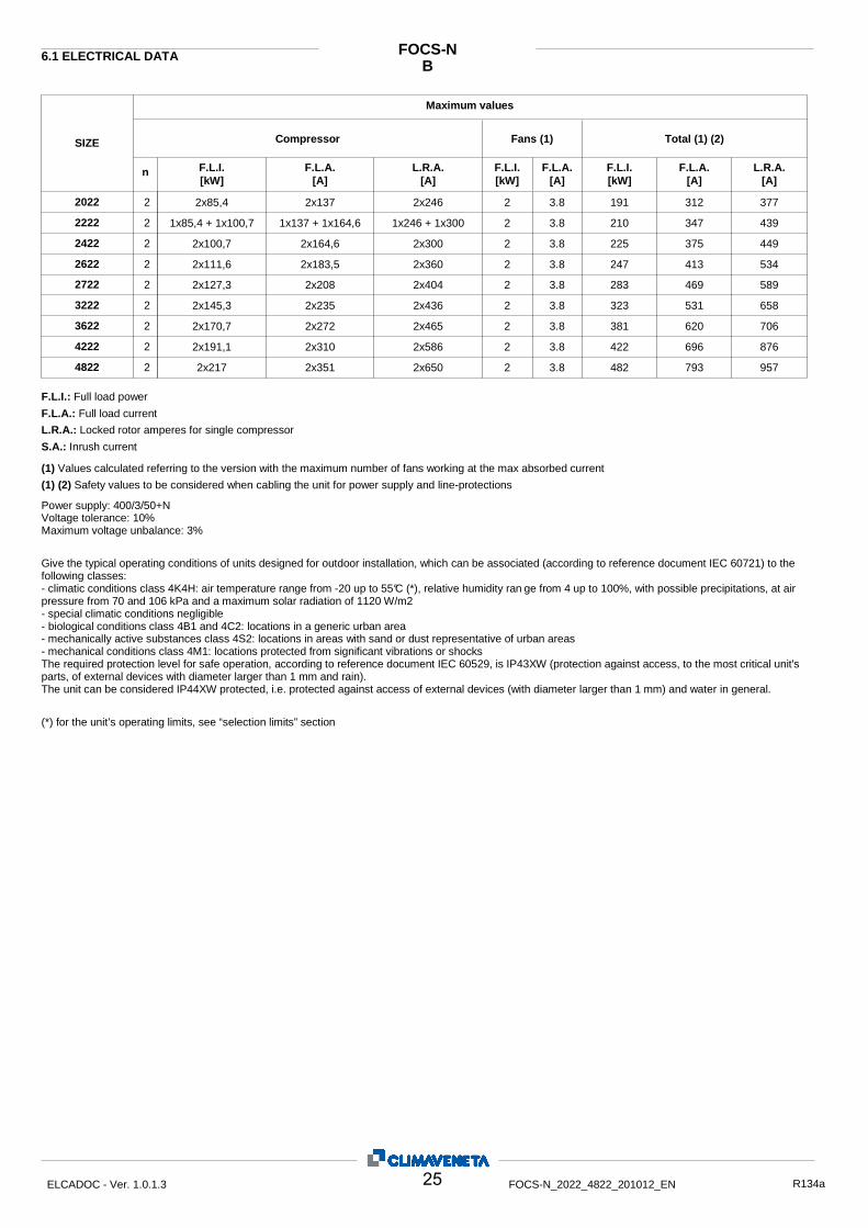
B FOCS-N
Maximum values
6.1 ELECTRICAL DATA
Compressor SIZE
n F.L.I. [kW]
F.L.A. [A]
L.R.A. [A]
L.R.A. [A]
F.L.A. [A]
F.L.I. [kW]
F.L.A. [A]
F.L.I. [kW]
Fans (1) Total (1) (2)
2022 2 2x85,4 2x137 2x246 2 3.8 191 312 377 2222 2 1x85,4 + 1x100,7 1x137 + 1x164,6 1x246 + 1x300 2 3.8 210 347 439 2422 2 2x100,7 2x164,6 2x300 2 3.8 225 375 449 2622 2 2x111,6 2x183,5 2x360 2 3.8 247 413 534 2722 2 2x127,3 2x208 2x404 2 3.8 283 469 589 3222 2 2x145,3 2x235 2x436 2 3.8 323 531 658 3622 2 2x170,7 2x272 2x465 2 3.8 381 620 706 4222 2 2x191,1 2x310 2x586 2 3.8 422 696 876 4822 2 2x217 2x351 2x650 2 3.8 482 793 957
F.L.I.: Full load power F.L.A.: Full load current L.R.A.: Locked rotor amperes for single compressor S.A.: Inrush current
(1) (2) Safety values to be considered when cabling the unit for power supply and line-protections (1) Values calculated referring to the version with the maximum number of fans working at the max absorbed current
Power supply: 400/3/50+N Voltage tolerance: 10% Maximum voltage unbalance: 3% Give the typical operating conditions of units designed for outdoor installation, which can be associated (according to reference document IEC 60721) to the following classes: - climatic conditions class 4K4H: air temperature range from -20 up to 55°C (*), relative humidity ran ge from 4 up to 100%, with possible precipitations, at air pressure from 70 and 106 kPa and a maximum solar radiation of 1120 W/m2 - special climatic conditions negligible - biological conditions class 4B1 and 4C2: locations in a generic urban area - mechanically active substances class 4S2: locations in areas with sand or dust representative of urban areas - mechanical conditions class 4M1: locations protected from significant vibrations or shocks The required protection level for safe operation, according to reference document IEC 60529, is IP43XW (protection against access, to the most critical unit's parts, of external devices with diameter larger than 1 mm and rain). The unit can be considered IP44XW protected, i.e. protected against access of external devices (with diameter larger than 1 mm) and water in general. (*) for the unit’s operating limits, see “selection limits” section
25 ELCADOC - Ver. 1.0.1.3 FOCS-N_2022_4822_201012_EN R134a

CA FOCS-N
Maximum values
ELECTRICAL DATA
Compressor SIZE
n F.L.I. [kW]
F.L.A. [A]
L.R.A. [A]
L.R.A. [A]
F.L.A. [A]
F.L.I. [kW]
F.L.A. [A]
F.L.I. [kW]
Fans (1) Total (1) (2)
2022 2 2x85,4 2x137 2x246 2 3.8 191 312 377 2222 2 1x85,4 + 1x100,7 1x137 + 1x164,6 1x246 + 1x300 2 3.8 210 347 439 2422 2 2x100,7 2x164,6 2x300 2 3.8 225 375 449 2622 2 2x111,6 2x183,5 2x360 2 3.8 247 413 534 2722 2 2x127,3 2x208 2x404 2 3.8 283 469 589 3222 2 2x145,3 2x235 2x436 2 3.8 323 531 658 3622 2 2x170,7 2x272 2x465 2 3.8 381 620 706 4222 2 2x191,1 2x310 2x586 2 3.8 430 711 891 4822 2 2x217 2x351 2x650 2 3.8 482 793 957
F.L.I.: Full load power F.L.A.: Full load current L.R.A.: Locked rotor amperes for single compressor S.A.: Inrush current
(1) (2) Safety values to be considered when cabling the unit for power supply and line-protections (1) Values calculated referring to the version with the maximum number of fans working at the max absorbed current
Power supply: 400/3/50+N Voltage tolerance: 10% Maximum voltage unbalance: 3% Give the typical operating conditions of units designed for outdoor installation, which can be associated (according to reference document IEC 60721) to the following classes: - climatic conditions class 4K4H: air temperature range from -20 up to 55°C (*), relative humidity ran ge from 4 up to 100%, with possible precipitations, at air pressure from 70 and 106 kPa and a maximum solar radiation of 1120 W/m2 - special climatic conditions negligible - biological conditions class 4B1 and 4C2: locations in a generic urban area - mechanically active substances class 4S2: locations in areas with sand or dust representative of urban areas - mechanical conditions class 4M1: locations protected from significant vibrations or shocks The required protection level for safe operation, according to reference document IEC 60529, is IP43XW (protection against access, to the most critical unit's parts, of external devices with diameter larger than 1 mm and rain). The unit can be considered IP44XW protected, i.e. protected against access of external devices (with diameter larger than 1 mm) and water in general. (*) for the unit’s operating limits, see “selection limits” section
26 ELCADOC - Ver. 1.0.1.3 FOCS-N_2022_4822_201012_EN R134a

LN-CA FOCS-N
Maximum values
ELECTRICAL DATA
Compressor SIZE
n F.L.I. [kW]
F.L.A. [A]
L.R.A. [A]
L.R.A. [A]
F.L.A. [A]
F.L.I. [kW]
F.L.A. [A]
F.L.I. [kW]
Fans (1) Total (1) (2)
2022 2 2x85,4 2x137 2x246 2 3.8 191 312 377 2222 2 1x85,4 + 1x100,7 1x137 + 1x164,6 1x246 + 1x300 2 3.8 210 347 439 2422 2 2x100,7 2x164,6 2x300 2 3.8 225 375 449 2622 2 2x111,6 2x183,5 2x360 2 3.8 247 413 534 2722 2 2x127,3 2x208 2x404 2 3.8 283 469 589 3222 2 2x145,3 2x235 2x436 2 3.8 323 531 658 3622 2 2x170,7 2x272 2x465 2 3.8 381 620 706 4222 2 2x191,1 2x310 2x586 2 3.8 430 711 891 4822 2 2x217 2x351 2x650 2 3.8 482 793 957
F.L.I.: Full load power F.L.A.: Full load current L.R.A.: Locked rotor amperes for single compressor S.A.: Inrush current
(1) (2) Safety values to be considered when cabling the unit for power supply and line-protections (1) Values calculated referring to the version with the maximum number of fans working at the max absorbed current
Power supply: 400/3/50+N Voltage tolerance: 10% Maximum voltage unbalance: 3% Give the typical operating conditions of units designed for outdoor installation, which can be associated (according to reference document IEC 60721) to the following classes: - climatic conditions class 4K4H: air temperature range from -20 up to 55°C (*), relative humidity ran ge from 4 up to 100%, with possible precipitations, at air pressure from 70 and 106 kPa and a maximum solar radiation of 1120 W/m2 - special climatic conditions negligible - biological conditions class 4B1 and 4C2: locations in a generic urban area - mechanically active substances class 4S2: locations in areas with sand or dust representative of urban areas - mechanical conditions class 4M1: locations protected from significant vibrations or shocks The required protection level for safe operation, according to reference document IEC 60529, is IP43XW (protection against access, to the most critical unit's parts, of external devices with diameter larger than 1 mm and rain). The unit can be considered IP44XW protected, i.e. protected against access of external devices (with diameter larger than 1 mm) and water in general. (*) for the unit’s operating limits, see “selection limits” section
27 ELCADOC - Ver. 1.0.1.3 FOCS-N_2022_4822_201012_EN R134a

SL-CA FOCS-N
Maximum values
ELECTRICAL DATA
Compressor SIZE
n F.L.I. [kW]
F.L.A. [A]
L.R.A. [A]
L.R.A. [A]
F.L.A. [A]
F.L.I. [kW]
F.L.A. [A]
F.L.I. [kW]
Fans (1) Total (1) (2)
2022 2 2x85,4 2x137 2x246 2 3.8 191 312 377 2222 2 1x85,4 + 1x100,7 1x137 + 1x164,6 1x246 + 1x300 2 3.8 210 347 439 2422 2 2x100,7 2x164,6 2x300 2 3.8 225 375 449 2622 2 2x111,6 2x183,5 2x360 2 3.8 247 413 534 2722 2 2x127,3 2x208 2x404 2 3.8 283 469 589 3222 2 2x145,3 2x235 2x436 2 3.8 323 531 658 3622 2 2x170,7 2x272 2x465 2 3.8 381 620 706 4222 2 2x191,1 2x310 2x586 2 3.8 430 711 891 4822 2 2x217 2x351 2x650 2 3.8 482 793 957
F.L.I.: Full load power F.L.A.: Full load current L.R.A.: Locked rotor amperes for single compressor S.A.: Inrush current
(1) (2) Safety values to be considered when cabling the unit for power supply and line-protections (1) Values calculated referring to the version with the maximum number of fans working at the max absorbed current
Power supply: 400/3/50+N Voltage tolerance: 10% Maximum voltage unbalance: 3% Give the typical operating conditions of units designed for outdoor installation, which can be associated (according to reference document IEC 60721) to the following classes: - climatic conditions class 4K4H: air temperature range from -20 up to 55°C (*), relative humidity ran ge from 4 up to 100%, with possible precipitations, at air pressure from 70 and 106 kPa and a maximum solar radiation of 1120 W/m2 - special climatic conditions negligible - biological conditions class 4B1 and 4C2: locations in a generic urban area - mechanically active substances class 4S2: locations in areas with sand or dust representative of urban areas - mechanical conditions class 4M1: locations protected from significant vibrations or shocks The required protection level for safe operation, according to reference document IEC 60529, is IP43XW (protection against access, to the most critical unit's parts, of external devices with diameter larger than 1 mm and rain). The unit can be considered IP44XW protected, i.e. protected against access of external devices (with diameter larger than 1 mm) and water in general. (*) for the unit’s operating limits, see “selection limits” section
28 ELCADOC - Ver. 1.0.1.3 FOCS-N_2022_4822_201012_EN R134a
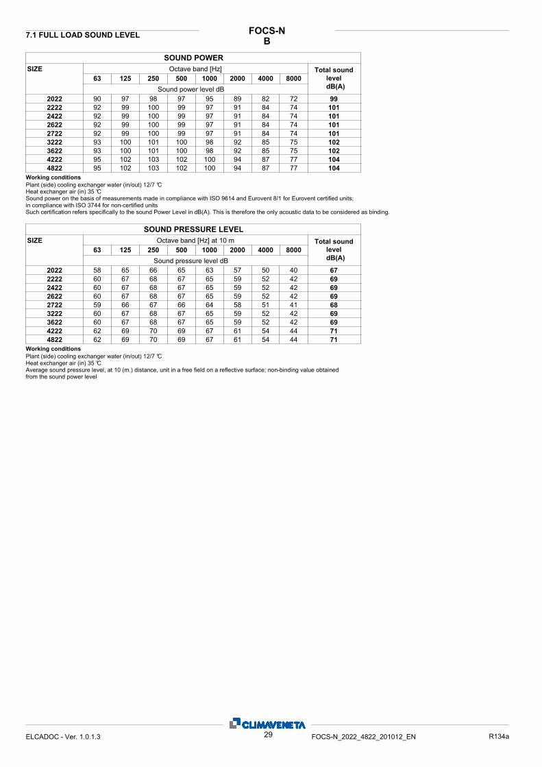
BFOCS-N7.1 FULL LOAD SOUND LEVEL
SIZE Octave band [Hz]2000100050025012563 80004000
Total sound leveldB(A)Sound power level dB
SOUND POWER
90 97 98 97 95 89 82 72 99202292 99 100 99 97 91 84 74 101222292 99 100 99 97 91 84 74 101242292 99 100 99 97 91 84 74 101262292 99 100 99 97 91 84 74 101272293 100 101 100 98 92 85 75 102322293 100 101 100 98 92 85 75 102362295 102 103 102 100 94 87 77 104422295 102 103 102 100 94 87 77 1044822
Plant (side) cooling exchanger water (in/out) 12/7 °CHeat exchanger air (in) 35 °CSound power on the basis of measurements made in compliance with ISO 9614 and Eurovent 8/1 for Eurovent certified units; in compliance with ISO 3744 for non-certified units Such certification refers specifically to the sound Power Level in dB(A). This is therefore the only acoustic data to be considered as binding.
Working conditions
SIZE Octave band [Hz] at 10 m2000100050025012563 80004000
Total sound leveldB(A)Sound pressure level dB
SOUND PRESSURE LEVEL
58 65 66 65 63 57 50 40 67202260 67 68 67 65 59 52 42 69222260 67 68 67 65 59 52 42 69242260 67 68 67 65 59 52 42 69262259 66 67 66 64 58 51 41 68272260 67 68 67 65 59 52 42 69322260 67 68 67 65 59 52 42 69362262 69 70 69 67 61 54 44 71422262 69 70 69 67 61 54 44 714822
Plant (side) cooling exchanger water (in/out) 12/7 °CHeat exchanger air (in) 35 °CAverage sound pressure level, at 10 (m.) distance, unit in a free field on a reflective surface; non-binding value obtained from the sound power level
Working conditions
29ELCADOC - Ver. 1.0.1.3 FOCS-N_2022_4822_201012_EN R134a
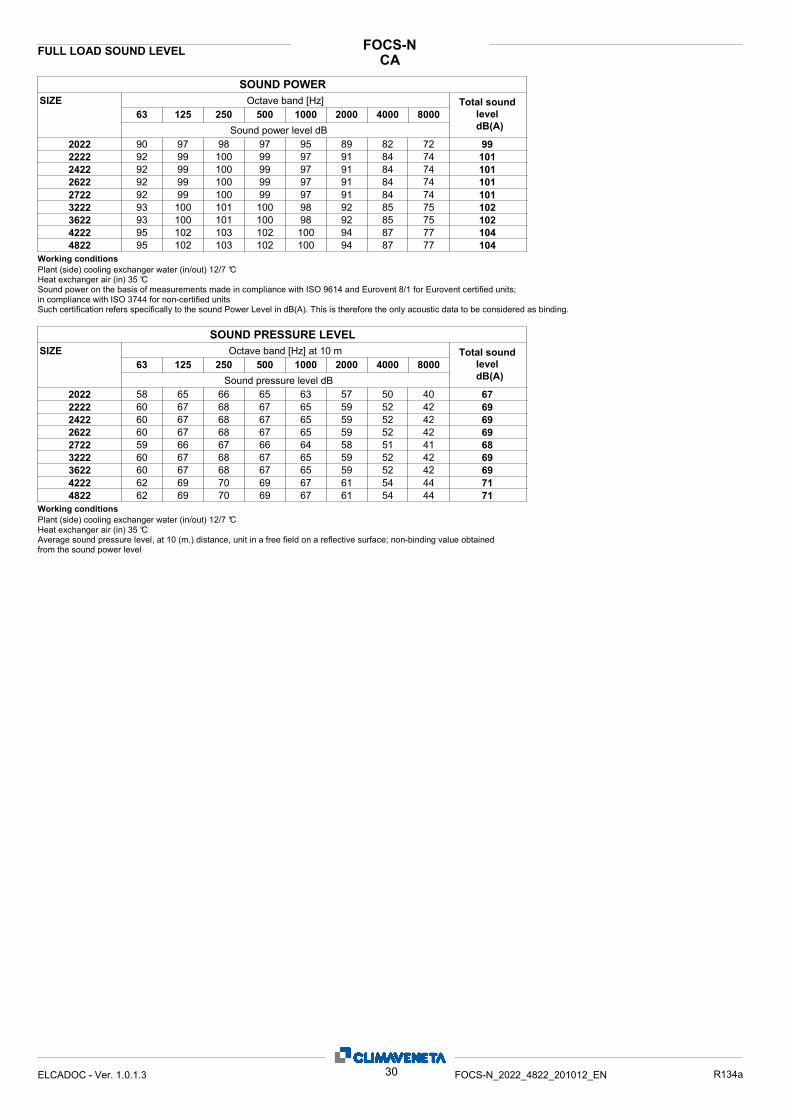
CAFOCS-NFULL LOAD SOUND LEVEL
SIZE Octave band [Hz]2000100050025012563 80004000
Total sound leveldB(A)Sound power level dB
SOUND POWER
90 97 98 97 95 89 82 72 99202292 99 100 99 97 91 84 74 101222292 99 100 99 97 91 84 74 101242292 99 100 99 97 91 84 74 101262292 99 100 99 97 91 84 74 101272293 100 101 100 98 92 85 75 102322293 100 101 100 98 92 85 75 102362295 102 103 102 100 94 87 77 104422295 102 103 102 100 94 87 77 1044822
Plant (side) cooling exchanger water (in/out) 12/7 °CHeat exchanger air (in) 35 °CSound power on the basis of measurements made in compliance with ISO 9614 and Eurovent 8/1 for Eurovent certified units; in compliance with ISO 3744 for non-certified units Such certification refers specifically to the sound Power Level in dB(A). This is therefore the only acoustic data to be considered as binding.
Working conditions
SIZE Octave band [Hz] at 10 m2000100050025012563 80004000
Total sound leveldB(A)Sound pressure level dB
SOUND PRESSURE LEVEL
58 65 66 65 63 57 50 40 67202260 67 68 67 65 59 52 42 69222260 67 68 67 65 59 52 42 69242260 67 68 67 65 59 52 42 69262259 66 67 66 64 58 51 41 68272260 67 68 67 65 59 52 42 69322260 67 68 67 65 59 52 42 69362262 69 70 69 67 61 54 44 71422262 69 70 69 67 61 54 44 714822
Plant (side) cooling exchanger water (in/out) 12/7 °CHeat exchanger air (in) 35 °CAverage sound pressure level, at 10 (m.) distance, unit in a free field on a reflective surface; non-binding value obtained from the sound power level
Working conditions
30ELCADOC - Ver. 1.0.1.3 FOCS-N_2022_4822_201012_EN R134a
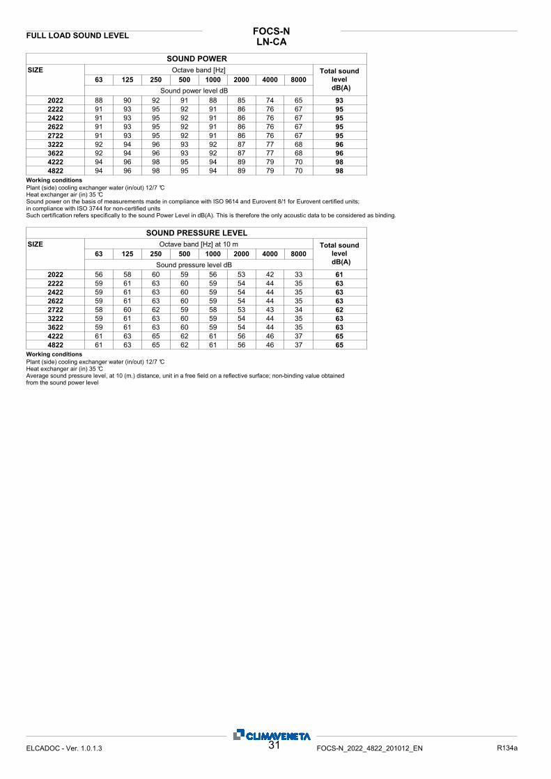
LN-CAFOCS-NFULL LOAD SOUND LEVEL
SIZE Octave band [Hz]2000100050025012563 80004000
Total sound leveldB(A)Sound power level dB
SOUND POWER
88 90 92 91 88 85 74 65 93202291 93 95 92 91 86 76 67 95222291 93 95 92 91 86 76 67 95242291 93 95 92 91 86 76 67 95262291 93 95 92 91 86 76 67 95272292 94 96 93 92 87 77 68 96322292 94 96 93 92 87 77 68 96362294 96 98 95 94 89 79 70 98422294 96 98 95 94 89 79 70 984822
Plant (side) cooling exchanger water (in/out) 12/7 °CHeat exchanger air (in) 35 °CSound power on the basis of measurements made in compliance with ISO 9614 and Eurovent 8/1 for Eurovent certified units; in compliance with ISO 3744 for non-certified units Such certification refers specifically to the sound Power Level in dB(A). This is therefore the only acoustic data to be considered as binding.
Working conditions
SIZE Octave band [Hz] at 10 m2000100050025012563 80004000
Total sound leveldB(A)Sound pressure level dB
SOUND PRESSURE LEVEL
56 58 60 59 56 53 42 33 61202259 61 63 60 59 54 44 35 63222259 61 63 60 59 54 44 35 63242259 61 63 60 59 54 44 35 63262258 60 62 59 58 53 43 34 62272259 61 63 60 59 54 44 35 63322259 61 63 60 59 54 44 35 63362261 63 65 62 61 56 46 37 65422261 63 65 62 61 56 46 37 654822
Plant (side) cooling exchanger water (in/out) 12/7 °CHeat exchanger air (in) 35 °CAverage sound pressure level, at 10 (m.) distance, unit in a free field on a reflective surface; non-binding value obtained from the sound power level
Working conditions
31ELCADOC - Ver. 1.0.1.3 FOCS-N_2022_4822_201012_EN R134a
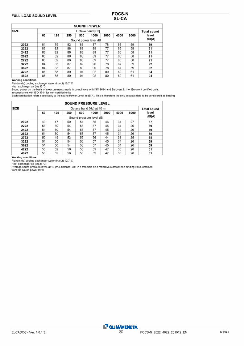
SL-CAFOCS-NFULL LOAD SOUND LEVEL
SIZE Octave band [Hz]2000100050025012563 80004000
Total sound leveldB(A)Sound power level dB
SOUND POWER
81 79 82 86 87 78 66 59 89202283 82 86 88 89 77 66 58 91222283 82 86 88 89 77 66 58 91242283 82 86 88 89 77 66 58 91262283 82 86 88 89 77 66 58 91272284 83 87 89 90 78 67 59 92322284 83 87 89 90 78 67 59 92362286 85 89 91 92 80 69 61 94422286 85 89 91 92 80 69 61 944822
Plant (side) cooling exchanger water (in/out) 12/7 °CHeat exchanger air (in) 35 °CSound power on the basis of measurements made in compliance with ISO 9614 and Eurovent 8/1 for Eurovent certified units; in compliance with ISO 3744 for non-certified units Such certification refers specifically to the sound Power Level in dB(A). This is therefore the only acoustic data to be considered as binding.
Working conditions
SIZE Octave band [Hz] at 10 m2000100050025012563 80004000
Total sound leveldB(A)Sound pressure level dB
SOUND PRESSURE LEVEL
49 47 50 54 55 46 34 27 57202251 50 54 56 57 45 34 26 59222251 50 54 56 57 45 34 26 59242251 50 54 56 57 45 34 26 59262250 49 53 55 56 44 33 25 58272251 50 54 56 57 45 34 26 59322251 50 54 56 57 45 34 26 59362253 52 56 58 59 47 36 28 61422253 52 56 58 59 47 36 28 614822
Plant (side) cooling exchanger water (in/out) 12/7 °CHeat exchanger air (in) 35 °CAverage sound pressure level, at 10 (m.) distance, unit in a free field on a reflective surface; non-binding value obtained from the sound power level
Working conditions
32ELCADOC - Ver. 1.0.1.3 FOCS-N_2022_4822_201012_EN R134a
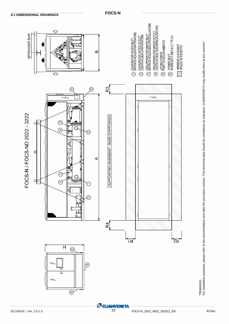
"RE
MA
RK
S:
For
inst
alla
tion
purp
oses
, ple
ase
refe
r to
the
docu
men
tatio
n se
nt a
fter
the
purc
hase
-con
trac
t. T
his
tech
nica
l dat
a sh
ould
be
cons
ider
ed a
s in
dica
tive.
CLI
MA
VE
NE
TA
may
mod
ify th
em a
t any
mom
ent."
FOCS-N 8.1 DIMENSIONAL DRAWINGS
33 ELCADOC - Ver. 1.0.1.3 FOCS-N_2022_4822_201012_EN R134a
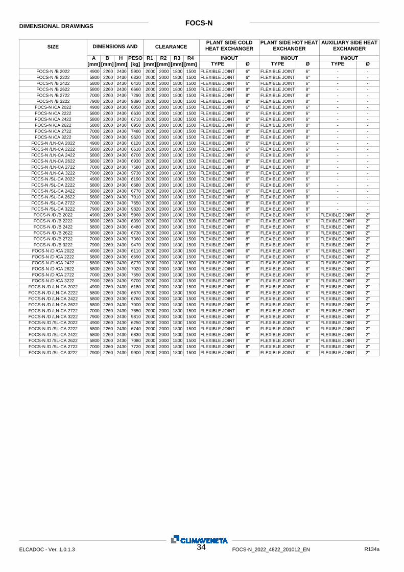
FOCS-N DIMENSIONAL DRAWINGS
Ø IN/OUT
Ø IN/OUT IN/OUT R4
[mm] R3
[mm] R2
[mm] R1
[mm] PESO [kg]
H [mm]
B [mm]
A [mm]
SIZE DIMENSIONS AND WEIGHTS
CLEARANCE PLANT SIDE COLD HEAT EXCHANGER
Ø TYPE TYPE TYPE
PLANT SIDE HOT HEAT EXCHANGER
AUXILIARY SIDE HEAT EXCHANGER
4900 2260 2430 5900 2000 2000 1800 1500 FLEXIBLE JOINT 6" FLEXIBLE JOINT 6" - - FOCS-N /B 2022 5800 2260 2430 6330 2000 2000 1800 1500 FLEXIBLE JOINT 6" FLEXIBLE JOINT 6" - - FOCS-N /B 2222 5800 2260 2430 6420 2000 2000 1800 1500 FLEXIBLE JOINT 6" FLEXIBLE JOINT 6" - - FOCS-N /B 2422 5800 2260 2430 6660 2000 2000 1800 1500 FLEXIBLE JOINT 8" FLEXIBLE JOINT 8" - - FOCS-N /B 2622 7000 2260 2430 7290 2000 2000 1800 1500 FLEXIBLE JOINT 8" FLEXIBLE JOINT 8" - - FOCS-N /B 2722 7900 2260 2430 9390 2000 2000 1800 1500 FLEXIBLE JOINT 8" FLEXIBLE JOINT 8" - - FOCS-N /B 3222 4900 2260 2430 6050 2000 2000 1800 1500 FLEXIBLE JOINT 6" FLEXIBLE JOINT 6" - - FOCS-N /CA 2022 5800 2260 2430 6630 2000 2000 1800 1500 FLEXIBLE JOINT 6" FLEXIBLE JOINT 6" - - FOCS-N /CA 2222 5800 2260 2430 6710 2000 2000 1800 1500 FLEXIBLE JOINT 6" FLEXIBLE JOINT 6" - - FOCS-N /CA 2422 5800 2260 2430 6950 2000 2000 1800 1500 FLEXIBLE JOINT 8" FLEXIBLE JOINT 8" - - FOCS-N /CA 2622 7000 2260 2430 7480 2000 2000 1800 1500 FLEXIBLE JOINT 8" FLEXIBLE JOINT 8" - - FOCS-N /CA 2722 7900 2260 2430 9620 2000 2000 1800 1500 FLEXIBLE JOINT 8" FLEXIBLE JOINT 8" - - FOCS-N /CA 3222 4900 2260 2430 6120 2000 2000 1800 1500 FLEXIBLE JOINT 6" FLEXIBLE JOINT 6" - - FOCS-N /LN-CA 2022 5800 2260 2430 6610 2000 2000 1800 1500 FLEXIBLE JOINT 6" FLEXIBLE JOINT 6" - - FOCS-N /LN-CA 2222 5800 2260 2430 6700 2000 2000 1800 1500 FLEXIBLE JOINT 6" FLEXIBLE JOINT 6" - - FOCS-N /LN-CA 2422 5800 2260 2430 6930 2000 2000 1800 1500 FLEXIBLE JOINT 8" FLEXIBLE JOINT 8" - - FOCS-N /LN-CA 2622 7000 2260 2430 7580 2000 2000 1800 1500 FLEXIBLE JOINT 8" FLEXIBLE JOINT 8" - - FOCS-N /LN-CA 2722 7900 2260 2430 9730 2000 2000 1800 1500 FLEXIBLE JOINT 8" FLEXIBLE JOINT 8" - - FOCS-N /LN-CA 3222 4900 2260 2430 6190 2000 2000 1800 1500 FLEXIBLE JOINT 6" FLEXIBLE JOINT 6" - - FOCS-N /SL-CA 2022 5800 2260 2430 6680 2000 2000 1800 1500 FLEXIBLE JOINT 6" FLEXIBLE JOINT 6" - - FOCS-N /SL-CA 2222 5800 2260 2430 6770 2000 2000 1800 1500 FLEXIBLE JOINT 6" FLEXIBLE JOINT 6" - - FOCS-N /SL-CA 2422 5800 2260 2430 7010 2000 2000 1800 1500 FLEXIBLE JOINT 8" FLEXIBLE JOINT 8" - - FOCS-N /SL-CA 2622 7000 2260 2430 7650 2000 2000 1800 1500 FLEXIBLE JOINT 8" FLEXIBLE JOINT 8" - - FOCS-N /SL-CA 2722 7900 2260 2430 9820 2000 2000 1800 1500 FLEXIBLE JOINT 8" FLEXIBLE JOINT 8" - - FOCS-N /SL-CA 3222 4900 2260 2430 5960 2000 2000 1800 1500 FLEXIBLE JOINT 6" FLEXIBLE JOINT 6" FLEXIBLE JOINT 2" FOCS-N /D /B 2022 5800 2260 2430 6390 2000 2000 1800 1500 FLEXIBLE JOINT 6" FLEXIBLE JOINT 6" FLEXIBLE JOINT 2" FOCS-N /D /B 2222 5800 2260 2430 6480 2000 2000 1800 1500 FLEXIBLE JOINT 6" FLEXIBLE JOINT 6" FLEXIBLE JOINT 2" FOCS-N /D /B 2422 5800 2260 2430 6730 2000 2000 1800 1500 FLEXIBLE JOINT 8" FLEXIBLE JOINT 8" FLEXIBLE JOINT 2" FOCS-N /D /B 2622 7000 2260 2430 7360 2000 2000 1800 1500 FLEXIBLE JOINT 8" FLEXIBLE JOINT 8" FLEXIBLE JOINT 2" FOCS-N /D /B 2722 7900 2260 2430 9470 2000 2000 1800 1500 FLEXIBLE JOINT 8" FLEXIBLE JOINT 8" FLEXIBLE JOINT 2" FOCS-N /D /B 3222 4900 2260 2430 6110 2000 2000 1800 1500 FLEXIBLE JOINT 6" FLEXIBLE JOINT 6" FLEXIBLE JOINT 2" FOCS-N /D /CA 2022 5800 2260 2430 6690 2000 2000 1800 1500 FLEXIBLE JOINT 6" FLEXIBLE JOINT 6" FLEXIBLE JOINT 2" FOCS-N /D /CA 2222 5800 2260 2430 6770 2000 2000 1800 1500 FLEXIBLE JOINT 6" FLEXIBLE JOINT 6" FLEXIBLE JOINT 2" FOCS-N /D /CA 2422 5800 2260 2430 7020 2000 2000 1800 1500 FLEXIBLE JOINT 8" FLEXIBLE JOINT 8" FLEXIBLE JOINT 2" FOCS-N /D /CA 2622 7000 2260 2430 7550 2000 2000 1800 1500 FLEXIBLE JOINT 8" FLEXIBLE JOINT 8" FLEXIBLE JOINT 2" FOCS-N /D /CA 2722 7900 2260 2430 9700 2000 2000 1800 1500 FLEXIBLE JOINT 8" FLEXIBLE JOINT 8" FLEXIBLE JOINT 2" FOCS-N /D /CA 3222 4900 2260 2430 6180 2000 2000 1800 1500 FLEXIBLE JOINT 6" FLEXIBLE JOINT 6" FLEXIBLE JOINT 2" FOCS-N /D /LN-CA 2022 5800 2260 2430 6670 2000 2000 1800 1500 FLEXIBLE JOINT 6" FLEXIBLE JOINT 6" FLEXIBLE JOINT 2" FOCS-N /D /LN-CA 2222 5800 2260 2430 6760 2000 2000 1800 1500 FLEXIBLE JOINT 6" FLEXIBLE JOINT 6" FLEXIBLE JOINT 2" FOCS-N /D /LN-CA 2422 5800 2260 2430 7000 2000 2000 1800 1500 FLEXIBLE JOINT 8" FLEXIBLE JOINT 8" FLEXIBLE JOINT 2" FOCS-N /D /LN-CA 2622 7000 2260 2430 7650 2000 2000 1800 1500 FLEXIBLE JOINT 8" FLEXIBLE JOINT 8" FLEXIBLE JOINT 2" FOCS-N /D /LN-CA 2722 7900 2260 2430 9810 2000 2000 1800 1500 FLEXIBLE JOINT 8" FLEXIBLE JOINT 8" FLEXIBLE JOINT 2" FOCS-N /D /LN-CA 3222 4900 2260 2430 6250 2000 2000 1800 1500 FLEXIBLE JOINT 6" FLEXIBLE JOINT 6" FLEXIBLE JOINT 2" FOCS-N /D /SL-CA 2022 5800 2260 2430 6740 2000 2000 1800 1500 FLEXIBLE JOINT 6" FLEXIBLE JOINT 6" FLEXIBLE JOINT 2" FOCS-N /D /SL-CA 2222 5800 2260 2430 6830 2000 2000 1800 1500 FLEXIBLE JOINT 6" FLEXIBLE JOINT 6" FLEXIBLE JOINT 2" FOCS-N /D /SL-CA 2422 5800 2260 2430 7080 2000 2000 1800 1500 FLEXIBLE JOINT 8" FLEXIBLE JOINT 8" FLEXIBLE JOINT 2" FOCS-N /D /SL-CA 2622 7000 2260 2430 7720 2000 2000 1800 1500 FLEXIBLE JOINT 8" FLEXIBLE JOINT 8" FLEXIBLE JOINT 2" FOCS-N /D /SL-CA 2722 7900 2260 2430 9900 2000 2000 1800 1500 FLEXIBLE JOINT 8" FLEXIBLE JOINT 8" FLEXIBLE JOINT 2" FOCS-N /D /SL-CA 3222
34 ELCADOC - Ver. 1.0.1.3 FOCS-N_2022_4822_201012_EN R134a
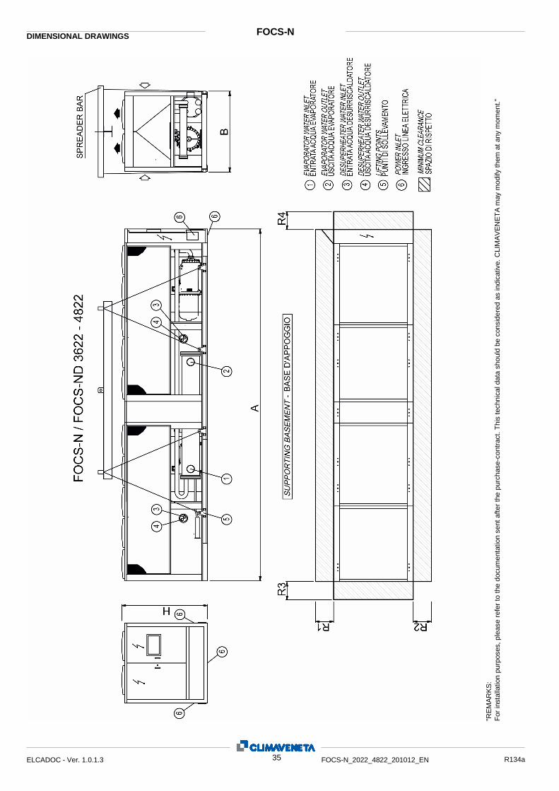
"RE
MA
RK
S:
For
inst
alla
tion
purp
oses
, ple
ase
refe
r to
the
docu
men
tatio
n se
nt a
fter
the
purc
hase
-con
trac
t. T
his
tech
nica
l dat
a sh
ould
be
cons
ider
ed a
s in
dica
tive.
CLI
MA
VE
NE
TA
may
mod
ify th
em a
t any
mom
ent."
FOCS-N DIMENSIONAL DRAWINGS
35 ELCADOC - Ver. 1.0.1.3 FOCS-N_2022_4822_201012_EN R134a
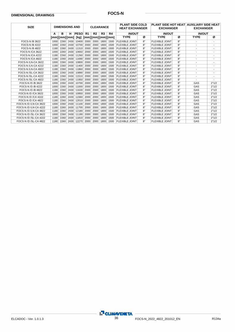
FOCS-N DIMENSIONAL DRAWINGS
Ø IN/OUT
Ø IN/OUT IN/OUT R4
[mm] R3
[mm] R2
[mm] R1
[mm] PESO [kg]
H [mm]
B [mm]
A [mm]
SIZE DIMENSIONS AND WEIGHTS
CLEARANCE PLANT SIDE COLD HEAT EXCHANGER
Ø TYPE TYPE TYPE
PLANT SIDE HOT HEAT EXCHANGER
AUXILIARY SIDE HEAT EXCHANGER
10000
2260 2430 10400 2000 2000 1800 1500 FLEXIBLE JOINT 8" FLEXIBLE JOINT 8" - - FOCS-N /B 3622 1000
0 2260 2430 10700 2000 2000 1800 1500 FLEXIBLE JOINT 8" FLEXIBLE JOINT 8" - - FOCS-N /B 4222
11800
2260 2430 11310 2000 2000 1800 1500 FLEXIBLE JOINT 8" FLEXIBLE JOINT 8" - - FOCS-N /B 4822 1000
0 2260 2430 10650 2000 2000 1800 1500 FLEXIBLE JOINT 8" FLEXIBLE JOINT 8" - - FOCS-N /CA 3622
11800
2260 2430 11260 2000 2000 1800 1500 FLEXIBLE JOINT 8" FLEXIBLE JOINT 8" - - FOCS-N /CA 4222 1180
0 2260 2430 11690 2000 2000 1800 1500 FLEXIBLE JOINT 8" FLEXIBLE JOINT 8" - - FOCS-N /CA 4822
10000
2260 2430 10800 2000 2000 1800 1500 FLEXIBLE JOINT 8" FLEXIBLE JOINT 8" - - FOCS-N /LN-CA 3622 1180
0 2260 2430 11400 2000 2000 1800 1500 FLEXIBLE JOINT 8" FLEXIBLE JOINT 8" - - FOCS-N /LN-CA 4222
11800
2260 2430 11860 2000 2000 1800 1500 FLEXIBLE JOINT 8" FLEXIBLE JOINT 8" - - FOCS-N /LN-CA 4822 1000
0 2260 2430 10890 2000 2000 1800 1500 FLEXIBLE JOINT 8" FLEXIBLE JOINT 8" - - FOCS-N /SL-CA 3622
11800
2260 2430 11510 2000 2000 1800 1500 FLEXIBLE JOINT 8" FLEXIBLE JOINT 8" - - FOCS-N /SL-CA 4222 1180
0 2260 2430 11950 2000 2000 1800 1500 FLEXIBLE JOINT 8" FLEXIBLE JOINT 8" - - FOCS-N /SL-CA 4822
10000
2260 2430 10700 2000 2000 1800 1500 FLEXIBLE JOINT 8" FLEXIBLE JOINT 8" GAS 2"1/2 FOCS-N /D /B 3622 1000
0 2260 2430 11000 2000 2000 1800 1500 FLEXIBLE JOINT 8" FLEXIBLE JOINT 8" GAS 2"1/2 FOCS-N /D /B 4222
11800
2260 2430 11630 2000 2000 1800 1500 FLEXIBLE JOINT 8" FLEXIBLE JOINT 8" GAS 2"1/2 FOCS-N /D /B 4822 1000
0 2260 2430 10950 2000 2000 1800 1500 FLEXIBLE JOINT 8" FLEXIBLE JOINT 8" GAS 2"1/2 FOCS-N /D /CA 3622
11800
2260 2430 11560 2000 2000 1800 1500 FLEXIBLE JOINT 8" FLEXIBLE JOINT 8" GAS 2"1/2 FOCS-N /D /CA 4222 1180
0 2260 2430 12010 2000 2000 1800 1500 FLEXIBLE JOINT 8" FLEXIBLE JOINT 8" GAS 2"1/2 FOCS-N /D /CA 4822
10000
2260 2430 11100 2000 2000 1800 1500 FLEXIBLE JOINT 8" FLEXIBLE JOINT 8" GAS 2"1/2 FOCS-N /D /LN-CA 3622 1180
0 2260 2430 11700 2000 2000 1800 1500 FLEXIBLE JOINT 8" FLEXIBLE JOINT 8" GAS 2"1/2 FOCS-N /D /LN-CA 4222
11800
2260 2430 12180 2000 2000 1800 1500 FLEXIBLE JOINT 8" FLEXIBLE JOINT 8" GAS 2"1/2 FOCS-N /D /LN-CA 4822 1000
0 2260 2430 11190 2000 2000 1800 1500 FLEXIBLE JOINT 8" FLEXIBLE JOINT 8" GAS 2"1/2 FOCS-N /D /SL-CA 3622
11800
2260 2430 11810 2000 2000 1800 1500 FLEXIBLE JOINT 8" FLEXIBLE JOINT 8" GAS 2"1/2 FOCS-N /D /SL-CA 4222 1180
0 2260 2430 12270 2000 2000 1800 1500 FLEXIBLE JOINT 8" FLEXIBLE JOINT 8" GAS 2"1/2 FOCS-N /D /SL-CA 4822
36 ELCADOC - Ver. 1.0.1.3 FOCS-N_2022_4822_201012_EN R134a
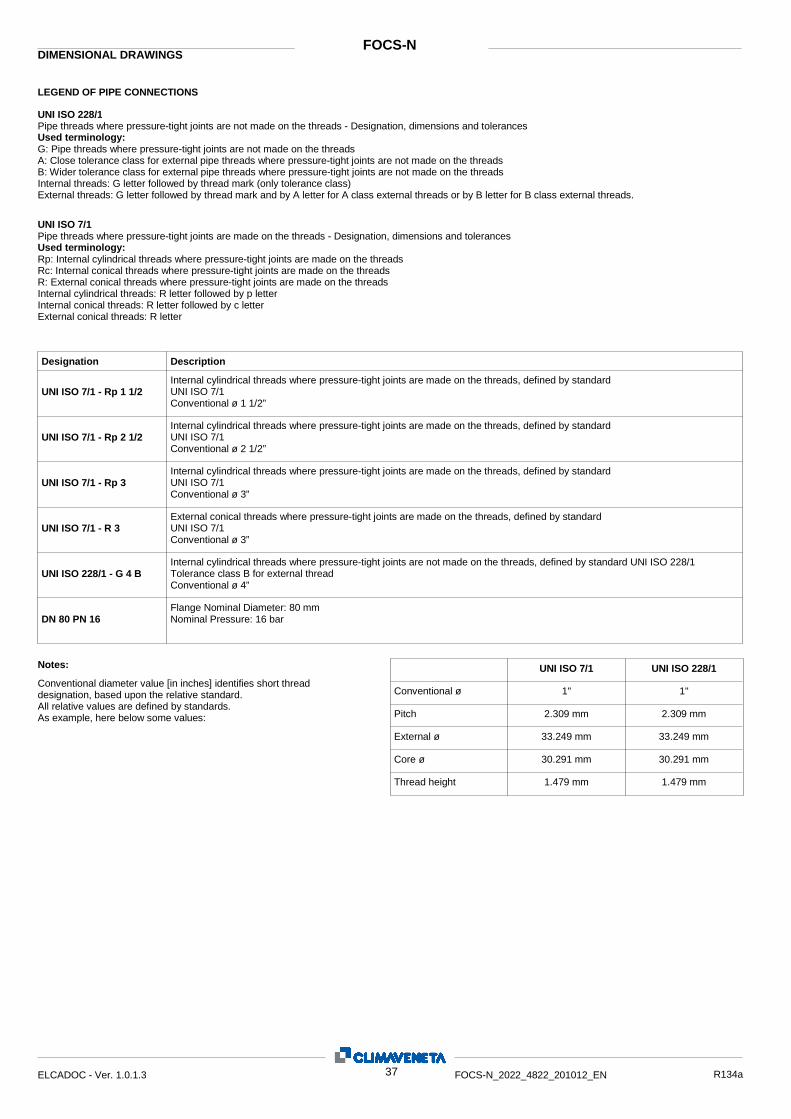
LEGEND OF PIPE CONNECTIONS
DIMENSIONAL DRAWINGS FOCS-N
UNI ISO 228/1 Pipe threads where pressure-tight joints are not made on the threads - Designation, dimensions and tolerances Used terminology: G: Pipe threads where pressure-tight joints are not made on the threads A: Close tolerance class for external pipe threads where pressure-tight joints are not made on the threads B: Wider tolerance class for external pipe threads where pressure-tight joints are not made on the threads Internal threads: G letter followed by thread mark (only tolerance class) External threads: G letter followed by thread mark and by A letter for A class external threads or by B letter for B class external threads. UNI ISO 7/1 Pipe threads where pressure-tight joints are made on the threads - Designation, dimensions and tolerances Used terminology: Rp: Internal cylindrical threads where pressure-tight joints are made on the threads Rc: Internal conical threads where pressure-tight joints are made on the threads R: External conical threads where pressure-tight joints are made on the threads Internal cylindrical threads: R letter followed by p letter Internal conical threads: R letter followed by c letter External conical threads: R letter
UNI ISO 7/1 - Rp 1 1/2
UNI ISO 7/1 - Rp 2 1/2
UNI ISO 7/1 - Rp 3
UNI ISO 228/1 - G 4 B
DN 80 PN 16
UNI ISO 7/1 - R 3
Designation Description Internal cylindrical threads where pressure-tight joints are made on the threads, defined by standard UNI ISO 7/1 Conventional ø 1 1/2” Internal cylindrical threads where pressure-tight joints are made on the threads, defined by standard UNI ISO 7/1 Conventional ø 2 1/2” Internal cylindrical threads where pressure-tight joints are made on the threads, defined by standard UNI ISO 7/1 Conventional ø 3” External conical threads where pressure-tight joints are made on the threads, defined by standard UNI ISO 7/1 Conventional ø 3” Internal cylindrical threads where pressure-tight joints are not made on the threads, defined by standard UNI ISO 228/1 Tolerance class B for external thread Conventional ø 4” Flange Nominal Diameter: 80 mm Nominal Pressure: 16 bar
UNI ISO 7/1 UNI ISO 228/1 1" 1"
2.309 mm 2.309 mm 33.249 mm 33.249 mm 30.291 mm 30.291 mm 1.479 mm 1.479 mm
Notes: Conventional diameter value [in inches] identifies short thread designation, based upon the relative standard. All relative values are defined by standards. As example, here below some values:
Conventional ø Pitch External ø Core ø Thread height
37 ELCADOC - Ver. 1.0.1.3 FOCS-N_2022_4822_201012_EN R134a
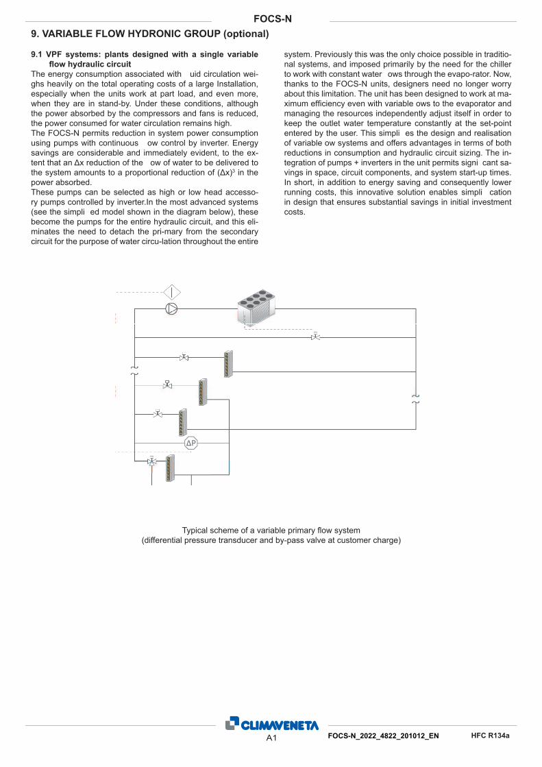
9.1 VPF systems: plants designed with a single variable
fl ow hydraulic circuit
The energy consumption associated with uid circulation wei-
ghs heavily on the total operating costs of a large Installation,
especially when the units work at part load, and even more,
when they are in stand-by. Under these conditions, although
the power absorbed by the compressors and fans is reduced,
the power consumed for water circulation remains high.
The FOCS-N permits reduction in system power consumption
using pumps with continuous ow control by inverter. Energy
savings are considerable and immediately evident, to the ex-
tent that an Δx reduction of the ow of water to be delivered to
the system amounts to a proportional reduction of (Δx)3 in the
power absorbed.
These pumps can be selected as high or low head accesso-
ry pumps controlled by inverter.In the most advanced systems
(see the simpli ed model shown in the diagram below), these
become the pumps for the entire hydraulic circuit, and this eli-
minates the need to detach the pri-mary from the secondary
circuit for the purpose of water circu-lation throughout the entire
system. Previously this was the only choice possible in traditio-
nal systems, and imposed primarily by the need for the chiller
to work with constant water ows through the evapo-rator. Now,
thanks to the FOCS-N units, designers need no longer worry
about this limitation. The unit has been designed to work at ma-
ximum effi ciency even with variable ows to the evaporator and
managing the resources independently adjust itself in order to
keep the outlet water temperature constantly at the set-point
entered by the user. This simpli es the design and realisation
of variable ow systems and offers advantages in terms of both
reductions in consumption and hydraulic circuit sizing. The in-
tegration of pumps + inverters in the unit permits signi cant sa-
vings in space, circuit components, and system start-up times.
In short, in addition to energy saving and consequently lower
running costs, this innovative solution enables simpli cation
in design that ensures substantial savings in initial investment
costs.
9. VARIABLE FLOW HYDRONIC GROUP (optional)
Typical scheme of a variable primary fl ow system
(differential pressure transducer and by-pass valve at customer charge)
A1 FOCS-N_2022_4822_201012_EN
FOCS-N
HFC R134a
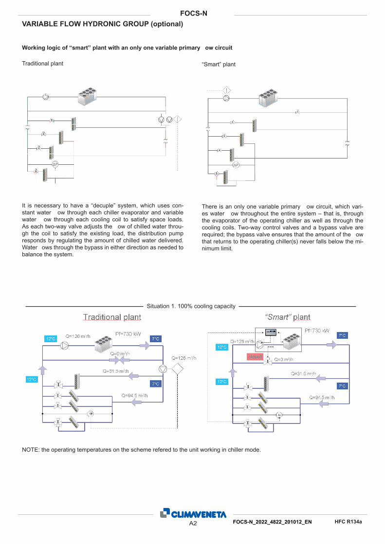
Working logic of “smart” plant with an only one variable primary ow circuit
Traditional plant “Smart” plant
It is necessary to have a “decuple” system, which uses con-
stant water ow through each chiller evaporator and variable
water ow through each cooling coil to satisfy space loads.
As each two-way valve adjusts the ow of chilled water throu-
gh the coil to satisfy the existing load, the distribution pump
responds by regulating the amount of chilled water delivered.
Water ows through the bypass in either direction as needed to
balance the system.
There is an only one variable primary ow circuit, which vari-
es water ow throughout the entire system – that is, through
the evaporator of the operating chiller as well as through the
cooling coils. Two-way control valves and a bypass valve are
required; the bypass valve ensures that the amount of the ow
that returns to the operating chiller(s) never falls below the mi-
nimum limit.
Situation 1. 100% cooling capacity
VARIABLE FLOW HYDRONIC GROUP (optional)
NOTE: the operating temperatures on the scheme refered to the unit working in chiller mode.
A2 FOCS-N_2022_4822_201012_EN
FOCS-N
HFC R134a
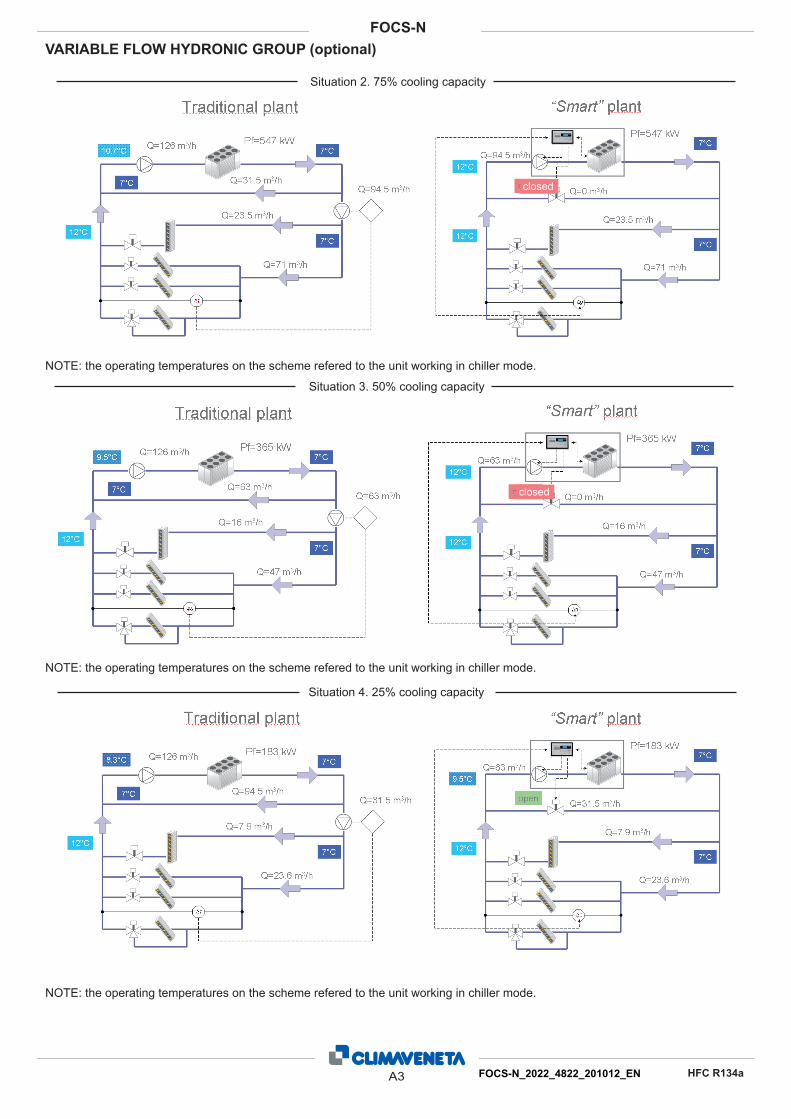
Situation 2. 75% cooling capacity
Situation 3. 50% cooling capacity
Situation 4. 25% cooling capacity
closed
closed
VARIABLE FLOW HYDRONIC GROUP (optional)
NOTE: the operating temperatures on the scheme refered to the unit working in chiller mode.
NOTE: the operating temperatures on the scheme refered to the unit working in chiller mode.
NOTE: the operating temperatures on the scheme refered to the unit working in chiller mode.
A3 FOCS-N_2022_4822_201012_EN
FOCS-N
HFC R134a
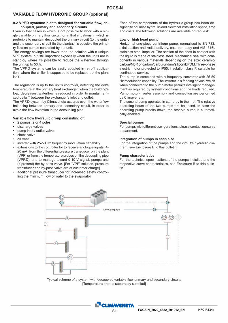
9.2 VPF.D systems: plants designed for variable fl ow, de-
coupled, primary and secondary circuits
Even in that cases in which is not possible to work with a sin-
gle variable primary fl ow circuit, or in that situations in which is
preferible to mantain decoupled the primary circuit (to the units)
and the secondary circuit (to the plants), it’s possible the prima-
ry fl ow on pumps controlled by the unit.
The energy savings are lower than the solution with a unique
VPF system, but still important expecially when the units are in
stand-by where it’s possible to reduce the waterfl ow through
the unit up to 50%.
The VPF.D systems can be easily adopted in retrofi t applica-
tion, where the chiller is supposed to be replaced but the plant
isn’t.
The regulation is up to the unit’s controller, detecting the delta
temperature at the primary heat exchanger: when the building’s
load decreases, waterfl ow is reduced in order to mantain a fi -
xed delta T between the exchanger’s inlet and outlet.
The VPF.D system by Climaveneta assures even the waterfl ow
balancing between primary and secondary circuit, in order to
avoid the fl ow inversion in the decoupling pipe.
Variable fl ow hydraulic group consisting of:
2 pumps, 2 or 4 poles •
discharge valves •
pump inlet / outlet valves •
check valve•
air vent•
inverter with 25-50 Hz frequency modulation capability•
extensions to the controller for to receive anologue inputs (4-•
20 mA) from the differential pressure transducer on the plant
(VPF) or from the temperature probes on the decoupling pipe
(VPF.D), and to manage toward 0-10 V signal, pumps and
(if present) the by-pass valve. [For “VPF” solution, pressure
transducer and by-pass valve are at customer charge]
additional pressure transducer for increased safety control- •
ling the minimum ow of water to the evaporator
Each of the components of the hydraulic group has been de-
signed to optimise hydraulic and electrical installation space, time
and costs.The following solutions are available on request:
Low or high head pump
Horizontal one-piece centrifuge pump, normalised to EN 733,
axial suction and radial delivery, cast iron body and AISI 316L
stainless steel impeller. The section of the shaft in contact with
the liquid is made of stainless steel. Mechanical seal with com-
ponents in various materials depending on the size: ceramic/
carbon/NBR or carbon/carburundum/silicon/EPDM.Three-phase
electric motor protected to IP55, insulation class F, suitable for
continuous service.
The pump is combined with a frequency converter with 25-50
Hz modulation capability. The inverter is a feeding device, which
when connected to the pump motor permits intelligent manage-
ment as required by system conditions and the loads required.
Pump motor-inverter assembly and connection are performed
by Climaveneta.
The second pump operates in stand-by to the rst. The relative
operating hours of the two pumps are balanced. In case the
operating pump breaks down, the reserve pump is automati-
cally enabled.
Special pumps
For pumps with different con gurations, please contact oursales
department.
Integration of pumps in each size
For the integration of the pumps and the circuit’s hydraulic dia-
gram, see Enclosure B to this bulletin.
Pump characteristics
For the technical speci cations of the pumps installed and the
respective curve characteristics, see Enclosure B to this bulle-
tin.
VARIABLE FLOW HYDRONIC GROUP (optional)
Typical scheme of a system with decoupled variable fl ow primary and secondary circuits
[Temperature probes separately supplied]
Decoupling pipe
A4 FOCS-N_2022_4822_201012_EN
FOCS-N
HFC R134a
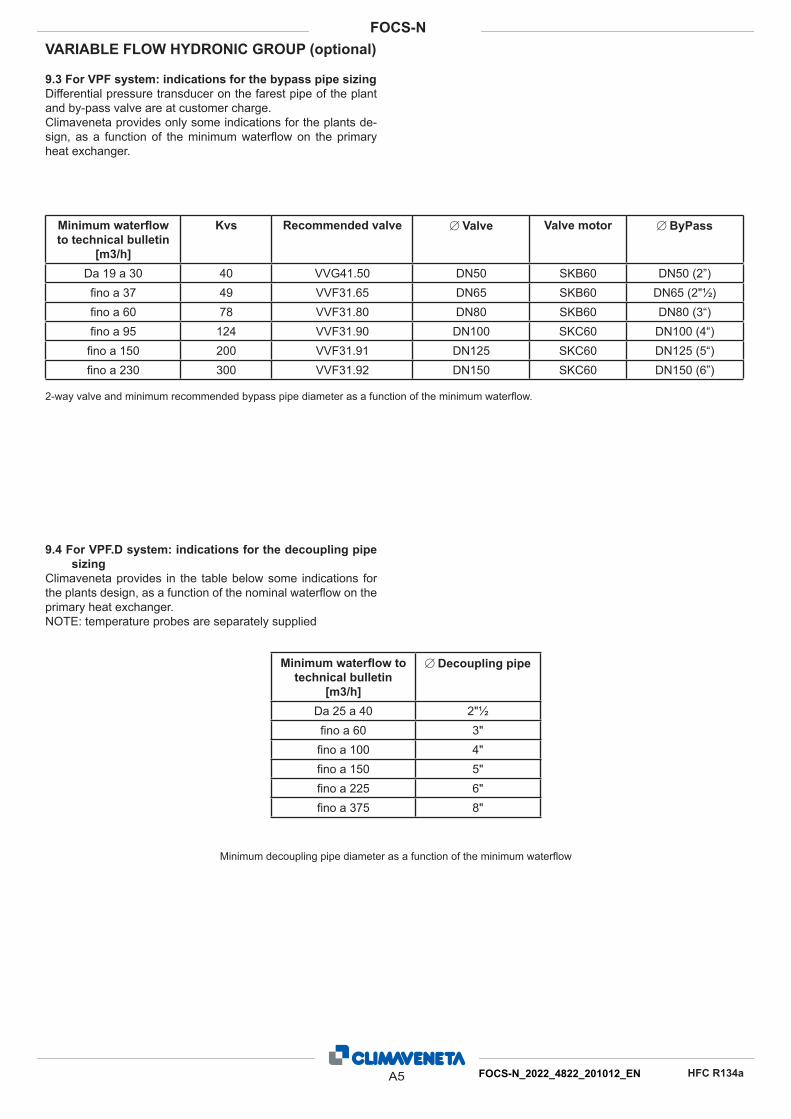
VARIABLE FLOW HYDRONIC GROUP (optional)
9.3 For VPF system: indications for the bypass pipe sizing
Differential pressure transducer on the farest pipe of the plant
and by-pass valve are at customer charge.
Climaveneta provides only some indications for the plants de-
sign, as a function of the minimum waterfl ow on the primary
heat exchanger.
9.4 For VPF.D system: indications for the decoupling pipe
sizing
Climaveneta provides in the table below some indications for
the plants design, as a function of the nominal waterfl ow on the
primary heat exchanger.
NOTE: temperature probes are separately supplied
Minimum waterfl ow
to technical bulletin
[m3/h]
Kvs Recommended valve ∅ Valve Valve motor ∅ ByPass
Da 19 a 30 40 VVG41.50 DN50 SKB60 DN50 (2”)
fi no a 37 49 VVF31.65 DN65 SKB60 DN65 (2"½)
fi no a 60 78 VVF31.80 DN80 SKB60 DN80 (3“)
fi no a 95 124 VVF31.90 DN100 SKC60 DN100 (4“)
fi no a 150 200 VVF31.91 DN125 SKC60 DN125 (5“)
fi no a 230 300 VVF31.92 DN150 SKC60 DN150 (6”)
2-way valve and minimum recommended bypass pipe diameter as a function of the minimum waterfl ow.
Minimum waterfl ow to
technical bulletin
[m3/h]
∅ Decoupling pipe
Da 25 a 40 2"½
fi no a 60 3"
fi no a 100 4"
fi no a 150 5"
fi no a 225 6"
fi no a 375 8"
Minimum decoupling pipe diameter as a function of the minimum waterfl ow
A5 FOCS-N_2022_4822_201012_EN
FOCS-N
HFC R134a
Climaveneta S.p.A. Via Sarson 57/c
36061 Bassano del Grappa (VI)
Italy
Tel +39 0424 509500
Fax +39 0424 509509
www.climaveneta.com
Climaveneta France 3, Village d’Entreprises
ZA de la Couronne des Prés
Avenue de la Mauldre
78680 Epone
France
Tel +33 (0)1 30 95 19 19
Fax +33 (0)1 30 95 18 18
www.climaveneta.fr
Climaveneta Deutschland Rhenus Platz, 2
59439 Holzwickede
Germany
Tel +49 2301 91222-0
Fax +49 2301 91222-99
www.climaveneta.de
Climaveneta
Espana - Top Clima Londres 67, 1° 4°
08036 Barcelona
Spain
Tel +34 963 195 600
Fax +34 963 615 167
www.climaveneta.com
Climaveneta Chat Union
Refrig. Equipment Co Ltd 88 Bai Yun Rd, Pudong Xinghuo
New dev. zone 201419 Shanghai
China
Tel 008 621 575 055 66
Fax 008 621 575 057 97
Climaveneta Polska Sp. z o.o. Ul. Sienkiewicza 13A
05-120 Legionowo
Poland
Tel +48 22 766 34 55-57
Fax +48 22 784 39 09
www.climaveneta.pl
Climaveneta India
Climate Technologies (P) LTD #3487, 14th Main, HAL 2nd stage,
Indiranagar, Bangalore 560008
India
Tel +91-80-42466900 - 949
Fax +91-80-25203540
Climaveneta UK LTD
Highlands Road,
Shirley Solihull
West Midlands B90 4NL
Tel: +44 (0)871 663 0664
Fax: +44 (0)871 663 1664
Freephone: 0800 801 819
www.climaveneta.co.uk
www.climaveneta.com