focus on bioenergie-technologien · 3 editorial liebe interessierte der bioenergietechnologien,...
TRANSCRIPT

FOKUSHEFTEnergetische Biomassenutzung
www.energetische-biomassenutzung.de 2015
FOCUS ON
Bioenergy-Technologies
Bioenergie-Technologien

Editorial 3
Konversionspfade – zur energetischen Biomassenutzung im 21. Jahrhundert 4Conversion pathways – towards biomass energy use in the 21st century
Bioenergie im Fokus 7Bioenergy in focus
Technologie-Cluster & Modellfälle 13Technology clusters & Model cases
Exkurse 16Digressions
Technologie-Steckbriefe 21Technology profiles
Anaerobe Vergärung 23Anaerobic digestion
Alkoholische Fermentation 37Alcoholic fermentation
Ver- / Umesterung, Hydroprocessing 44Esterification / transesterification, hydroprocessing
Verbrennung 51Combustion
Biomassevergasung 67Biomass gasification
Entwicklungstrends – Herausforderungen an die technische Weiterentwicklung 76Developmental trends - challenges for further technical advancement
Anaerobe Vergärung 77Anaerobic digestion
Alkoholische Fermentation 79Alcoholic fermentation
Ver- / Umesterung, Hydroprocessing 80Esterification / transesterification, hydroprocessing
Verbrennung 81Combustion
Biomassevergasung 83Biomass gasification
Abkürzungsverzeichnis 85Abbreviations
Literatur 89References
Anhang 91Annex
Impressum 95Imprint
EDITORIAL
HINTERGRUND BACKGROUND
TECHNOLOGIE-CLUSTER & MODELLFÄLLE TECHNOLOGY CLUSTERS & MODEL CASES
TECHNOLOGIE-STECKBRIEFE TECHNOLOGY PROFILES
ENTWICKLUNGSTRENDS DEVELOPMENTAL TRENDS

3
EditorialLiebe Interessierte der Bioenergietechnologien,
Bioenergie ist heute der wichtigste erneuerbare Ener-gieträger in Deutschland und der Welt. Der fortlaufende Übergang von traditioneller zu moderner bis hin zu hoch integrierter Bioenergiebereitstellung. Viele positive Effek-te konnten bisher dadurch erreicht werden und moderne Technologien und Know-How rund um Bioenergie sind weltweit auf dem Vormarsch. Um die Bioenergie auch im 21. Jahrhundert eine Erfolgsstory werden zu lassen, ist es notwendig, weitergehende Fortschritte im Techno-logietransfer, in der Energieeffizienz und der Gesamt-performance zu erzielen. Der entscheidende Schritt für die zukünftige Entwicklung wird die Integration neuer, verbesserter Bioenergietechnologien und -konzepte in Energie- und Stoffsystem(e) mit deren vielfältigen, sich ändernden Nachfragen (Quantität) und Anforderungen (Qualität) nach Bioenergie sein.
Es gibt eine Vielzahl von technischen Lösungsansätzen zur Nutzung verschiedenster Biomassen bzw. Bioener-gieträgern für die Bereitstellung von Wärme, Strom und Biokraftstoffen. Die Bandbreite reicht vom einfachen Holzfeuer zum Kochen bis hin zur biomassebasierten Kerosinproduktion für die Luftfahrt. In diesem Fokusheft werden exemplarisch heutige und zukünftige Technolo-gieoptionen beschrieben, um ein besseres Verständnis für deren zukünftiges Potenzial und etwaiger Herausfor-derungen zu erlangen.
Die vorgestellten Bioenergie-Optionen, ursprünglich erarbeitet im Kontext des Forschungsverbundvorhabens “Meilensteine 2030”, zeigen zum einen die Heraus-forderungen für die zukünftige Implementierung auf, zum anderen können die Informationen von Akteuren und Entscheidungsträgern in Wissenschaft, Forschung, Wirtschaft und Politik genutzt werden. Des Weiteren bietet die Zusammenstellung eine Ausgangsbasis für die Harmonisierung von Daten zu Bioenergietechnologien.
Ich möchte an dieser Stelle vielen Dank dem gesamten Team aussprechen, die mit ihrem Einsatz zum Gelingen dieses Fokusheftes beigetragen haben.
Viel Spaß beim Lesen des Fokusheftes!
Dear bioenergy technology enthusiasts,
Today bioenergy is the most important renewable energy source in Germany and the world. There is an ongoing transition from traditional to modern and even integ-rated bioenergy provision. Many positive effects have already been achieved, and advanced technologies and know-how are spreading worldwide. To make bioenergy a further success story in the 21st century, improvements in technology transfer, energy efficiency and overall performance are still necessary. For future development, the essential step will be the integration of new and improved technologies and concepts into the energy (and material) system(s), meeting not just the diverse and changing future demands in terms of quantity, but also raising the associated quality standards of such energy produced from biomass resources.
There are wide-ranging technological approaches for the utilisation of different biomass and bioenergy carriers in the provision of heat, power and liquid biofuels, ranging from firewood for cooking to advanced bio-based jet fuel production. This brochure aims to provide descriptions of relevant technological options for bioenergy provision today and in the future, and to give a better understan-ding of their future potential as well as the associated challenges.
The profiles of selected bioenergy options, which were originally compiled as part of the joint research project “Milestones 2030” , highlight the diverse implementation potentials of the various technologies going forward. In addition, the information may be useful for stakeholders and decision-makers in science, research, business and politics. Furthermore, the compilation provides a basis for the harmonisation of data on bioenergy technologies.
I would like to thank the team who prepared this brochure for their great efforts in collecting and reviewing the immense amount of data.
I hope you will enjoy reading it!
Prof Daniela Thrän Head of department Bioenergy Systems, DBFZ

4
© cropenergies
Konversionspfadezur energetischen Biomassenutzung im 21. Jahrhundert
Conversion pathwaystowards biomass energy use in the 21st century
Autoren:Jens Ponitka, Oliver Arendt, Volker Lenz, Jaqueline Daniel-Gromke, Walter Stinner, Andreas Ortwein, Martin Zeymer, Arne Gröngröft, Franziska Müller-Langer, Marco Klemm, Julian Braun, Walter Zeug (DBFZ)
Daniela Thrän (DBFZ / UFZ)
Sinead O‘Keeffe, Markus Millinger (UFZ)

5
Background – Bioenergy technologies and key parameters
Photoautotrophic organisms, particularly terrestrial plants, employ photosynthesis to convert solar radiation into chemical energy, which is then used to produce high-energy organic compounds. These compounds form the basis for complex supply networks, including not only human nutrition, but also the supply of building compo-nents, material products or energy. Biomass-based energy constitutes approximately 10.4 % (2013: about 59 EJ) (IEA 2015) of global primary energy consumption and accounts for around three quarters of renewables (13.5 % of global PEC).
In addition to traditional uses of biomass, such as cooking and heating (firewood, manure), significant progress has been achieved over recent years in developing new technological procedures and potential applications. Feedstocks containing oil, sugar, starch or lignocellulose, as well as residual and waste materials, are employed in various conversion processes to generate the required final or useful energy in the form of electricity, of tech-nologies, heat or biofuels (see Figure 1). There is a wide spectrum ranging from modern heat-generating tech-nologies for households, to efficient system-integrated heat and electricity generating technologies (using solid
Biogene Energieträger Biomass Energy Sources
Energiepflanzen
Energy Crops
Nebenprodukte und Rückstände
By-Products & Residues
Organischer Abfall
Organic Waste
ERNTE, SAMMELN, BEREITSTELLUNG HARVEST, COLLECTION, PROVISION
VERBRENNUNG COMBUSTION
Fester Brennstoff(z.B. Pellets, Holz,thermochemisch
behandelten Brennstoffe)
Solid Biofuel(e.g. Pellets, Wood,
thermochemically treated Fuels)
Gasförmiger Brennstoff(z.B. Synthesegas,
Biomethan, Biogas)
Gaseous Biofuel(e.g. Synthesis Gas,
Biomethane, Biogas)
Flüssiger Brennstoff(z.B. Pflanzenöl, Biodiesel,
Bioethanol, Fischer-Tropsch-Diesel, HVO/HEFA)
Liquid Biofuel(e.g. Vegetable Oil, Biodiesel,
Bioethanol, Fischer-Tropsch-Fuels, HVO/HEFA)
Kraft Power Wärme Heat
BIOCHEMISCHE KONVERSION
BIO-CHEMICAL CONVERSION
THERMOCHEMISCHE KONVERSION
THERMO-CHEMICAL CONVERSION
PHYSIKALISCH-CHEMISCHEKONVERSION
PHYSICAL-CHEMICALCONVERSION
Karbonisierung
Carbonisation
Vergasung
Gasification
Pyrolyse
Pyrolysis
AlkoholischeGärung
AlcoholicFermentation
AnaerobeVergärung
AnaerobicDigestion
Kompostierung
Composting
Pressung /Extraktion
Pressing /Extraction
Umesterung
Transesterification
Abbildung 1: Schematischer Aufbau von Bereitstellungsketten, Quelle: Eigene Darstellung nach Kaltschmitt et al. 2009; Thrän 2015)
Figure 1: Biomass conversion pathways, source: Own representa-tion based on Kaltschmitt et al. 2009; Thrän 2015
Hintergrund – Bioenergietechnologien und Kenngrößen Photoautotrophe Lebewesen, insbesondere Landpflan-zen, wandeln solare Strahlung über den Prozess der Photosynthese in chemische Energie um, welche dann zum Aufbau energiereicher, organischer Verbindungen genutzt wird. Diese Verbindungen bilden die Grundlage vielfältiger Nahrungsketten, so auch der Ernährung der Menschen, aber auch der Bereitstellung von z. B. Bauma-terialien, stofflichen Produkten oder Energie. Biomasse-basierte Energie stellt insgesamt etwa 10,4 % (2013: ca. 59 EJ) (IEA 2015) des weltweiten Primärenergieverbrau-ches dar und damit etwa Dreiviertel der erneuerbaren Energien (13,5 % des globalen PEV).
Neben traditionellen Nutzungsformen der Biomasse wie Brennstoffe (Holz, Dung) zum Kochen und Heizen, wurden in den letzten Jahrzenten weitreichende Fortschritte in den technologischen Verfahren und Nutzungsmöglich-keiten erreicht. Aus öl-, zucker-, stärke-, oder lignozellulo-sehaltigen Rohstoffen, Reststoffen und Abfällen werden über verschiedene Umwandlungsprozesse die gewünsch-te End- bzw. Nutzenergie in Form von Strom, Wärme und Biokraftstoffen (siehe Abbildung 1) bereitgestellt. Von modernen Wärmeerzeugungstechnologien für Haushalte bis hin zu effizienten, systemdienlichen Wärme- und Stromerzeugungstechnologien aus Festbrennstoffen,

6
Energiepflanzen und landwirtschaftlichen Reststoffen, von der hochwertigen Kaskadennutzung von Abfällen bis hin zur Biokraftstofferzeugung für die Sicherstellung von Mobilität gibt es ein breites Spektrum. Auch wenn im globalen Maßstab die traditionelle Nutzungsformen noch mit knapp 60 % einen hohen Stellenwert innerhalb der energetischen Biomassenutzung besitzt (Chum et al. 2011; IEA 2013; Smith et al. 2014), können die moder-nen, integrierten Erzeugungstechnologien inzwischen in unterschiedlichen Anwendungsfeldern als etabliert bezeichnet werden (Thrän 2015) .
In vielen nationalen1 wie globalen2 Studien, Szenarien und Roadmaps ist Bioenergie ein relevanter, in der Regel quantitativ weiter steigender, Bestandteil des Klimaschut-zes und der Systemtransformation der Energieversor-gung. Die Ausschöpfung von Optimierungspotenzialen und die Integration neuer Anlagenkonzepte und Bioener-gietechnologien ins Energiesystem hängen dabei unter anderem ab von:
n den Rahmenbedingungen (u. a. globale Trends der Stoff- und Energieversorgung),
n der Nachfrage (u. a. Umfang erneuerbarer Alternati-ven),
n der Biomasseverfügbarkeit (u. a. Bevölkerungsent-wicklung, Entwicklung Bioökonomie).
Andererseits wird die Berücksichtigung verschiedener Technologien in z. B. Szenarien oder Roadmaps und die Abschätzung des Implementierungspotenzials entschei-dend bestimmt von den:
i) angenommenen / verwendeten Technologien und den
ii) entsprechenden ökologischen, ökonomischen und technischen Kenngrößen (wie zum Beispiel Anla-gengröße, Investitionsaufwendungen, Rohstoffart, Rohstoffkosten, Emissionen, Gestehungskosten, Umwandlungseffizienz) inklusive deren zukünftigen Entwicklungen bzw. Entwicklungsmöglichkeiten.
1 Zum Beispiel: BMWi/BMU 2010; Kirchner & Matthes 2009; Nitsch et al. 2012; Prognos/ewi/gws 2014; Repenning et al. 2014; Schle-singer et al. 2010; SRU 2011; WBGU 20092 Zum Beispiel: IEA 2013; OECD/IEA 2011, 2012; OECD/IEA 2010; WWF et al. 2011
fuels, energy crops and agricultural residues) to highly efficient cascading use of waste to biofuel production for mobility. At global level traditional forms of biomass use still play an important role. Accounting for nearly 60 % of the utilisation of biomass for energy purposes (Chum et al. 2011; IEA 2013; Smith et al. 2014), modern integrated production technologies can now be described as well-established in various fields of application (Thrän 2015).
In many national1 and global2 studies, scenarios and roadmaps, bioenergy is a relevant, usually quantita-tively growing, component of climate protection and the transformation of energy supply systems. The tapping of optimization potentials and the integration of new plant concepts and bioenergy technologies into the energy supply system depends, among other things, on:
n the general economic conditions (incl. global trends in material and energy supplies),
n demand (incl. the quantity of renewable alternatives), n the availability of biomass (incl. population develop-
ment, development of the bio-economy).
On the other hand, the consideration of various techno-logies, for example in scenarios or roadmaps, and the evaluation of their potential for implementation crucially depends on:
i) the assumed / employed technologies and,
ii) the corresponding ecological, economic and technical parameters (such as the size of plants, investment costs, type of feedstock, cost of feedstocks, emis-sions, levelised cost of energy, conversion efficiency), including their future development and potential for development.
1 e. g. BMWi/BMU 2010; Kirchner & Matthes 2009; Nitsch et al. 2012; Prognos/ewi/gws 2014; Repenning et al. 2014; Schlesinger et al. 2010; SRU 2011; WBGU 20092 e. g. IEA 2013; OECD/IEA 2011, 2012; OECD/IEA 2010; WWF et al. 2011
Diese technischen, ökologischen und ökonomi-schen Kenngrößen verschiedener Technologien sind sowohl für die heutige Einsatzfähigkeit als auch hinsichtlich des Weiterentwicklungs-potenzials und der zukünftig umfassenden Integration von Bioenergie ins Energiesystem relevant. Daraus ergibt sich die Relevanz für die Darstellung dieser Basisinformationen in den Steckbriefen.
These environmental, economic and technical parameters of various technologies are relevant both for their deployability today and for their potential for further development and the comprehensive integration of bioenergy into the energy system in the future. Hence, the relevance of the presentation of this basic information in the profiles.

77
This broschure illustrates different bioenergy plant concepts in the form of “Feedstock – Technology – Final product” combinations. It presents, in particular, the development potentials of bioenergy technologies up to the year 2050 on the basis of selected, representative model cases. These model cases and the data (in particular, relating to the status quo) and selected trends (efficiency [MJ feedstock input/ MJ main output], levelised cost of energy, technical develop-ments) are presented in the form of profiles. They provide the reader with points of reference as to how established technologies might develop and adapt to changing require-ments and also the potentials and challenges arising from technologies which are not yet established on the market.
How the technology concepts were selected For a transparent, clearly structured database showing the development potentials of bioenergy plants, the large number of existing and theoretically possible supply chains and the resulting possible combinations of feedstocks, technologies, plant sizes and end-uses have been aggregated into a selec-tion of technology clusters. This is necessary because even the established technologies show a high degree of variation; particularly in plant size, use of feedstocks (price, quantity and quality of feedstocks) and plant management (full load hours).
In particular, those “Feedstocks – Technology – Final product” combinations were examined in detail assessing for:
n those combinations which had a significant conversion contribution (biomass to end energy) to Germany’s energy demands and
n “typical” (i.e. in terms of the existing number of plants) or combinations which are considered today as having potential to meet future energy demands (based on expert view on political goals, market trends, technology potential).
Bioenergie im FokusBioenergyin Focus
In diesem Fokusheft werden verschiedene Bioenergie-anlagenkonzepte in Form von „Rohstoff-Technologie-Endprodukt“-Kombinationen abgebildet und insbeson-dere die Entwicklungsmöglichkeiten der Bioenergie-technologien bis zum Jahr 2050 anhand ausgewählter, repräsentativer Modellfälle vorgestellt. Diese Modellfälle sowie die Daten (insb. Status Quo) und ausgewählte Charakterisitka (Wirkungsgrade [MJ Rohstoffinput/MJ Hauptoutput], Gestehungskosten, technische Entwicklun-gen) sind in Form von Steckbriefen dargestellt. Sie geben dem Leser Anhaltspunkte, wie sich etablierte Technologi-en weiterentwickeln und sich verändernden Anforderun-gen anpassen können, aber auch, welche Möglichkeiten und Herausforderungen sich bei derzeit nicht am Markt etablierten Technologien ergeben.
Auswahl der Technologiekonzepte
Für eine transparente, übersichtliche Datenbasis der Entwicklungsmöglichkeiten von Bioenergieanlagen wurde die Vielzahl an vorhandenen und theoretisch möglichen Bereitstellungsketten und damit Kombinationsmöglich-keiten von Rohstoffen, Technologien, Anlagengrößen und Endnutzungen zu einer Auswahl an Technologie-Clustern aggregiert. Dies ist notwendig, da bereits bei den etab-lierten Technologien große Bandbreiten insbesondere bei Anlagengröße, Rohstoffeinsatz (Rohstoffpreis, Quantität und Qualität) und Anlagenmanagement (Vollaststunden) zu verzeichnen sind.
Näher betrachtet wurden insbesondere die „Rohstoff-Technologie-Endprodukt“-Kombinationen, n durch die prinzipiell ein nennenswerter Umwand-
lungsbeitrag (Biomasse zu Nutzenergie) in Deutsch-land erfolgen kann und
n welche möglichst repräsentativ (basierend auf Anlagenbestand) bzw. aus heutiger Sicht aus Exper-tensicht (politische Ziele, Trends auf den Märkten, Technologiepotenzial) zukunftsträchtig sind.
© Rainer_Sturm_pixelio.de

8
The selection of the technology clusters was also based on:
n the inclusion of a comprehensive range of biomass feedstocks from various sources and with different characteristics
n the inclusion of all basic conversion processes3 (ther-mo-chemical [combustion, gasification], bio-chemical [alcoholic fermentation, anaerobic digestion], physical-chemical [transesterification, hydroprocess-ing]) and end-products
n the accounting for the status quo of biomass and conversion combinations, as well as foreseeable trends in technological development, anticipated market availability (technology status) and the requirements of the energy supply system
The technology clusters form the basis for evaluating4 the representative and anticipated model cases in the profiles presented.
The model cases derived from the technology clusters and presented in detail in the profiles, are shown in Table 1. Table 2 provides an overview of the model cases examined in this publication and their major parameters. The spectrum of technologies ranges from simple, already existing plants with an annual biomass consumption of approximately 1 tonne to highly complex plants that will only become available over the longer term and will have an annual biomass consumption of up to one million tonnes.
3 Certain conversion pathways which have not been taken into consideration (such as co-combustion of biomass in coal-fired power stations, algal biofuels, Bio-GtL, Bio-CCS) and specific sub-processes (e.g. torrefaction or hydrothermal processes) are discussed in the digression on pp. 19 in this brochure.4 Determination and evaluation combined and based on the large amounts of data (e.g. from national monitoring electricity from biomass [Scheftelowitz et al. 2015] and the biofuel sector [Naumann et al. 2014]) and experience (including the funding programme “Biomass Energy Use”) relating to bioenergy and bioenergy technologies (see also [Thrän et al. 2010]) in Germany.
Die Auswahl der Technologie-Cluster orientierte sich des Weiteren an:
n einer möglichst vollständigen Abdeckung von Biomas-serohstoffen verschiedenster Herkunft und Eigen-schaften
n der Abdeckung aller grundsätzlichen Konversionsver-fahren3 (thermo-chemisch [Verbrennung, Vergasung], bio-chemisch [alkoholische Fermentation, anaerobe Vergärung], physikalisch-chemisch [Umesterung, Hydroprocessing]) und Endprodukte
n Berücksichtigung des Status quo und absehbarer Trends der Technologieentwicklung, der erwarteten Marktverfügbarkeit (Technologiestatus) und der Bedarfe des Energiesystems
Ausgehend von den Technologie-Clustern erfolgte die Auslegung4 repräsentativer bzw. wahrscheinlicher Modell-fälle in den dargestellten Steckbriefen.
Die aus den Technologie-Clustern abgeleiteten und in den Steckbriefen im Detail dargestellten Modellfälle sind in Tabelle 1 aufgeführt. Eine Übersicht über die in diesem Heft betrachteten Modellfälle und deren wichtigsten Kenngrößen gibt Tabelle 2. Die Bandbreite der Techno-logien reicht dabei von einfachen, realisierten Anlagen mit einem jährlichen Biomassebedarf von etwa 1 Tonne bis hin zu hoch komplexen, erst längerfristig verfügbaren Anlagen mit einem Biomassebedarf von bis zu 1 Million Tonnen pro Jahr.
3 Auf bestimmte, nicht berücksichtigte Konversionspfade (z. B. Biomassemitverbrennung in Kohlekraftwerken, Kraftstoffe aus Algen, Bio-GtL, Bio-CCS) oder spezielle Teilprozesse (z. B. Torre-fizierung oder hydrothermale Prozesse) wird im Exkurs S. 19 in diesem Fokusheft hingewiesen.4 Basierend auf den umfänglichen Daten (z. B. nationales Moni-toring Stromerzeugung aus Biomasse [Scheftelowitz et al. 2015] und Biokraftstoffsektor [Naumann et al. 2014]) und Erfahrungen (u. a. Förderprogramm „Energetische Biomassenutzung“) rund um die Bioenergie und Bioenergietechnologien (siehe auch [Thrän et al. 2010]) in Deutschland.

9
Strom- / Wärmebereitstellung (KWK)Electricity / heating (CHP)
WärmeHeat
BiokraftstoffBiofuels
Pflanzenöl-BHKWPlant oil CHP unit
[2 MWel]
EinzelraumfeuerungSingle room heater
[8 kW]
Ethanol-ZuckerEthanol from sugar
[93 MWKS/biofuel]
GuD-Heizkraftwerk (Dampfturbine) Gas and steam cogeneration plant
(steam turbine) [6 MWel]
Holzpelletkessel (Zentralheizung) Wood pellet fired boiler (central heating)
[15 kW]
Ethanol-Stärke Ethanol from starch
[183 MWKS/biofuel]
Mikro-KWK (Stirling) Micro-CHP unit (Stirling)
[3 kWel]
Automatische Kleinfeuerungsanlage (Holzhackschnitzel)
Automatic small solid fuel boiler system (woodchips)
[500 kW]
Ethanol-LignozelluloseEthanol from lignocellulose
[61 MWKS/biofuel]
ORC-HeizkraftwerkORC heat and power station
[250 kWel]
Biomethan (Biogasaufbereitung / -einspeisung
Biomethane (biogas upgrading and feed-in)
[ca./approx. 7 MWBiomethan/Biomethane]
Güllekleinanlage Small liquid manure biogas plant
[80 kWel]
FAME a: zentral / b: dezentral
a: centralised / b: decentralised a: [245 MWKS/biofuel]b: [37 MWKS/biofuel]
Biogasanlage-Nawaro Biogas plant - renewable feedstock
[500 kWel]
HVO / HEFA [ca. 292 MWKS/biofuel]
Biomethan (Biogasaufbereitung / -einspeisung input+ KWK )
Biomethane (Biogas processing / input) + CHP unit
[700 Nm³/h] + [BHKW 2 MWel]
Bioabfallvergärung Biowaste digestion
[800 kWel] Bio-SNG
[25 MWSNG]
KleinvergaserSmall-scale gasifier
[0,038 MWel]
BtL / FT-KraftstoffeBtL / FT-fuels
[ca. 177 MWKS/biofuel]Vergaser KWK CHP gasifier[10,8 MWel]
Abkürzungen: ORC: Organic Rankine Cycle; DT: Dampfturbine; HHS: Holzhackschnitzel; KWK: Kraft-Wärme-Kopplung; Bio-SNG: Bio Substitute Natural Gas (Methan aus biogenen Festbrennstoffen); BtL: biomass to liquid; HVO: Hydrogenated Vegetable Oil, HEFA: hydroprozessierte Ester und Fettsäuren, FT: Fischer-Tropsch
Abbreviations: ORC: Organic Rankine Cycle; ST: Steam Turbine; CHP: Combined Heat and Power; Bio-SNG: Bio Substitute Natural Gas (methane from biogenic solid fuels); BtL: Biomass to Liquid; HVO: Hydrogenated Vegetable Oil; HEFA: Hydrotreated Esters and Fatty Acids, FT: Fischer-Tropsch
n Verbrennung Combustion
n Anaerobe Vergärung Anaerobic digestion
n Alkoholische Fermentation Alcoholic fermentation
n Umesterung / Hydroprocessing Transesterification / Hydroprocessing
n Biomassevergasung Biomass gasification
Table 1: Main products and classification of the model cases presented in the profiles
Tabelle 1: Hauptprodukte und Einordnung der in den Steckbriefen betrachteten Modellfälle

10
Schlüsselparameter in den TechnologiesteckbriefenDie einzelnen Modellfälle sowie die Clusterbeschreibun-gen sind in den Steckbriefen dargestellt und beinhalten folgende Informationen und Schlüsselparameter:
n Status Quo (Anlagenbestand, installierte Leistung, Produktion) in Deutschland
n Clusterkurzbeschreibung (Prozesskette, Leistungs-spektrum, Entwicklungsstand, Varianz [z. B. Anlagen-auslegung, Brennstoffflexibilität] der Technologie)
n Parameter der Modellanlagen n Ausstoß, Kapazität, Volllaststunden, Laufzeitn Inputs und Outputs (stofflich, energetisch)n Konversionsgrad5
n Kosten (kapitalgebundene Kosten, Lernrate6, Kosten-anteile, Gestehungskosten, Erlöse)
n Entwicklungsbedarf und Ausblickn Auswahl relevanter Literatur
Ausgehend vom heutigen Stand der Technologien wird in den Steckbriefen auf mögliche Entwicklungen und Trends (z. B. Technologieentwicklung, Rahmenbedingungen) eingegangen und diese für das Jahr 2050 anhand einzel-ner Parameter aufgezeigt. Die Informationen können zum Beispiel als Input für Szenarien und Modellierungen dienen. Für die Berechnung der auch in den Steckbriefen exemplarisch dargelegten Zahlen zu den Gestehungskos-ten (siehe Exkurs 1, S. 16), welche einen groben Vergleich der Technologien ermöglichen sollen, sind weitere wichtige Parameter und Annahmen notwendig, welche nicht vollumfänglich Teil der Steckbriefe sind. Diese sind im Anhang dargelegt.
5 Eine absolute Vergleichbarkeit verschiedener Prozesse ist mit den dargestellten Wirkungsgraden nur bedingt möglich. Zu verschiedenen Wirkungsgraden und Exkurs zu Bilanzeffekten Brennwert und Heizwert siehe auch „Methodenhandbuch“ (Thrän & Pfeiffer 2013).6 Die ökonomischen Lernraten von in der Regel < 25 % beziehen sich auf die Reduktion der Investitionsaufwendungen und kommen bei einer Verdopplung der installierten Kapazität zum Tragen. Bei zukünftigen, nicht etablierten Technologien kann in Simulations-rechnungen ebenfalls ein (externer) Lerneffekt durch Forschung und Entwicklung unterstellt werden. Unberücksichtigt bleiben hierbei mögliche Erhöhungen der Investitionen aufgrund erhöhter Umweltauflagen.
Key parameters in the technology profiles
The individual model cases or cluster descriptions are presented in the profiles and contain the following infor-mation and key parameters:
n status quo (existing units, installed capacity, produc-tion) in Germany
n Brief description of the cluster (process chain, capac-ity range, state of development, technology variance [e.g. plant design, fuel flexibility])
n Parameters of the model plant n output, capacity, full load hours, service life n inputs and outputs (materials, energy)n conversion efficiency5 n costs (capital-related costs, learning rate6, cost
components, levelised costs of energy, revenues) n Development needs and prospects n Relevant literature sources
Taking the current state of technology as the starting point, the profiles consider possible developments and trends (e.g. technical advances, general conditions) and show them for the year 2050 on the basis of individual parameters (conversion efficiencies). This information can be used, for example, as inputs for scenarios and models. The calculation of the sample figures in the profiles concerning the levelised cost of energy (see digression 1, pp. 16), which are intended to facilitate comparisons between the different technologies, require further important parameters and assumptions, not all of which are included in the profiles. These are presented in the Annex.
5 With the efficiencies presented, absolute comparability between different processes is only possible to a certain extent. Concern-ing different efficiencies, and for a digression discussing the balance sheet effects of superior and inferior calorific value, see also the “Method Handbook” in the english version (Thrän & Pfeiffer 2015).6 The economic learning rates, which are usually < 25 %, relate to the reduction of investment costs and take effect when the installed capacity is doubled. Within simulation calculations for future, not yet established technologies, it can also be assumed that an (external) learning effect will be achieved through research and development. This does not take account of possible increases in investment owing to stricter environmental regula-tions.

11
0
50 000
100 000
150 000
200 000
250 000
1990 1995 2000 2005 2010 2015
Ende
nerg
ieve
rbra
uch
bzw
. Bru
ttos
trom
erze
ugun
gFi
nal e
nerg
y co
nsum
tion/
gros
s ele
ctric
ity p
rodu
ctio
n [
GWh]
Endenergieverbrauch Wärme Final energy consumption heat
Endenergieverbrauch Verkehr Final energy consumption
Bruttostromerzeugung Gross electricity production
Abbildung 2: Entwicklung der Bioenergiebereitstellung in Deutschland, Quelle: Zeitreihe bis 2014 auf Basis (BMWi 2015) unter Verwendung von Daten AGEE-Stat, Prognose 2015 (Eigene Annahmen)
Figure 2: Development of bioenergy production in Germany, source: Time series up to 2014 based on (BMWi 2015) using data from AGEE-Stat, Prognosis 2015 (own assumptions)
Status quo Technologie Bioenergie: Fokus Deutschland
Die Bioenergie hat in Deutschland, ermöglicht durch ambitionierte Ziele und förderliche Rahmenbedin-gungen (u. a. Förderung von Strom über das EEG, Biokraftstoffquoten, Marktanreizprogramme (Wärme), Forschungsförderung), in allen Sektoren einen Zubau erfahren (Abbildung 2) und leistet (2014) mit insgesamt 194,5 TWh (ca. 700 PJ) (BMWi 2015) einen entscheiden-den Beitrag zur Energiewende.
The status quo in bioenergy technology: Focus on Germany
Particularly in Germany, thanks to the ambitious goals and positive framework conditions, such as subsidies for electricity generation through the Renewable Energies Act, quotas for biofuels, market incentive programmes (heat) and the funding of research, bioenergy has experienced growth in all sectors, as shown in Figure 2. Currently (2014), bioenergy contributes a total of 194.5 TWh (about 700 PJ) (BMWi 2015) to the success of the transformati-on of energy systems.

12
Die heutige Strombereitstellung aus Biomasse in Deutschland (2014: 49,1 TWh) wird dominiert durch die gekoppelte Strom- und Wärmeproduktion in Biogasan-lagen und mittleren bis großen Heizkraftwerken. Sehr geringe Strommengen werden noch durch Pflanzenöl-BHKW bereitgestellt (Scheftelowitz et al. 2015). Einen geringeren Anteil, aber gegebenenfalls eine zunehmende Rolle, haben Biomethan (Biogasaufbereitung / -einspei-sung und -verstromung-), kleine, güllebasierte Biogas-anlagen und kleintechnische Holzvergaser (< 1 MW mit motorischer Produktgasnutzung).
Der Wärmesektor (2014: 113,4 TWh) wird neben der Wärmenutzung aus KWK-Systemen insbesondere durch eine Vielzahl kleiner Feuerungssysteme (z. B. Kamine, Pelletkessel, Holzhackschnitzelkessel) für die reine Wärmebereitstellung geprägt. Tendenziell können verga-sungsbasierte Systeme (ggfs. KWK) einen weitergehen-den Beitrag zu Emissionsminderung und Systemintegrati-on fester Biomasse leisten.
Die Nutzung von Biokraftstoffen (2014: 32,0 TWh) in Deutschland wird heute von Biodiesel (vorrangig Raps) gefolgt von Ethanol dominiert (Naumann et al. 2014). Zu einem geringeren Anteil wird in Deutschland Biomethan als Kraftstoff genutzt, welches zumeist über das Erdgas-netz verteilt wird. Das Bild könnte sich zukünftig weiter diversifizieren. So könnten zunehmend Biomethan aus der Biogasaufbereitung, Ethanol der 2. Generation aus Stroh, HVO/HEFA und gasförmige oder flüssige Kraftstoffe aus Vergasungsprozessen (z. B. Bio-SNG, BTL) produziert und als Kraftstoffe im Verkehrssektor eingesetzt werden.
Electricity generation from biomass in Germany (2014: 49.1 TWh) is currently dominated by combined electricity and heat generation in biogas plants and medium-sized to large thermal power stations. Very small amounts of electricity are produced by plant-oil CHP units (Schef-telowitz et al. 2015). A smaller but growing role is being played by biomethane (biogas upgrading, feed-in to gas grid and utilisation for electricity generation), small liquid manure-based biogas plants and small-scale wood gasi-fiers (< 1 MW with motoric product gas utilisation).
The heating sector (2014: 113.4 TWh) is characterised by the utilisation of heat from CHP systems and also by the large number of small-scale combustion systems (e.g. open-hearth fireplaces, pellet boilers, woodchip boilers) intended purely for the generation of heat. Trends indica-te that gasification-based systems (if necessary CHP) will be able to make a further contribution to the reduction of emissions and the system integration of solid biomass.
The use of biofuels (2014: 32.0 TWh) in Germany is currently dominated by biodiesel (primarily derived from rapeseed oil) and is followed by ethanol (Naumann et al. 2014). Biomethane is used as a fuel in Germany to a smaller extent, with most of it being distributed via the natural gas supply network. This situation may well become more diversified in future. For example, biomethane could increasingly be produced through the processing of biogas. Ethanol could be produced from straw. HVO/HEFA and gaseous or liquid fuels from gasification processes (Bio-SNG, BtL). All of these could be used as fuels in the transport sector.
12
13
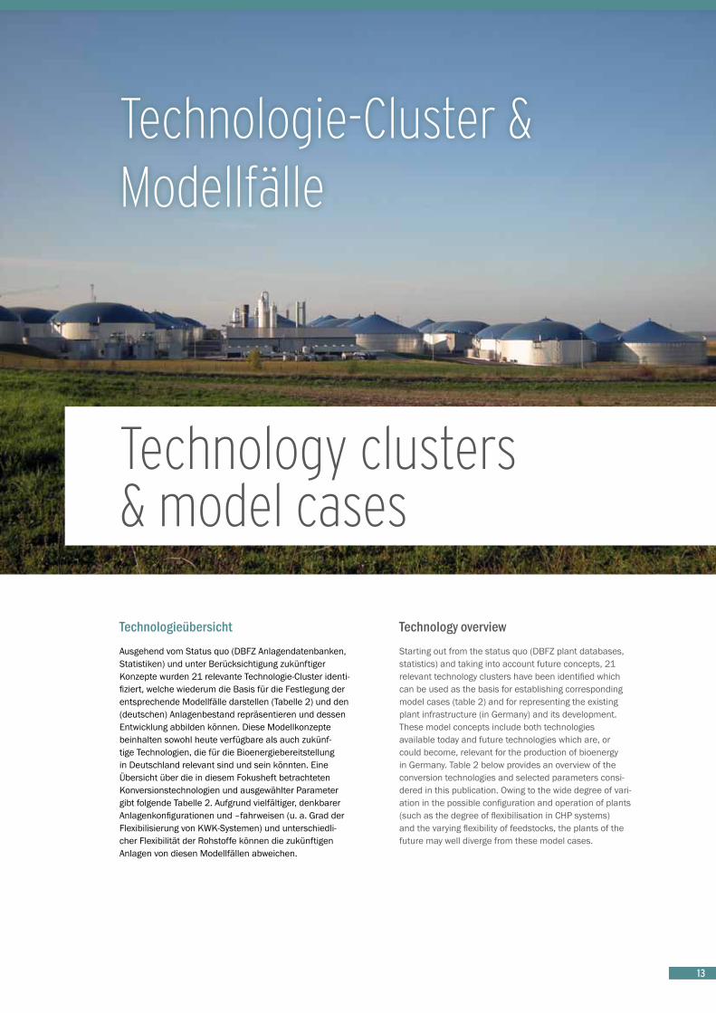
TechnologieübersichtAusgehend vom Status quo (DBFZ Anlagendatenbanken, Statistiken) und unter Berücksichtigung zukünftiger Konzepte wurden 21 relevante Technologie-Cluster identi-fiziert, welche wiederum die Basis für die Festlegung der entsprechende Modellfälle darstellen (Tabelle 2) und den (deutschen) Anlagenbestand repräsentieren und dessen Entwicklung abbilden können. Diese Modellkonzepte beinhalten sowohl heute verfügbare als auch zukünf-tige Technologien, die für die Bioenergiebereitstellung in Deutschland relevant sind und sein könnten. Eine Übersicht über die in diesem Fokusheft betrachteten Konversionstechnologien und ausgewählter Parameter gibt folgende Tabelle 2. Aufgrund vielfältiger, denkbarer Anlagenkonfigurationen und –fahrweisen (u. a. Grad der Flexibilisierung von KWK-Systemen) und unterschiedli-cher Flexibilität der Rohstoffe können die zukünftigen Anlagen von diesen Modellfällen abweichen.
Technology overviewStarting out from the status quo (DBFZ plant databases, statistics) and taking into account future concepts, 21 relevant technology clusters have been identified which can be used as the basis for establishing corresponding model cases (table 2) and for representing the existing plant infrastructure (in Germany) and its development. These model concepts include both technologies available today and future technologies which are, or could become, relevant for the production of bioenergy in Germany. Table 2 below provides an overview of the conversion technologies and selected parameters consi-dered in this publication. Owing to the wide degree of vari-ation in the possible configuration and operation of plants (such as the degree of flexibilisation in CHP systems) and the varying flexibility of feedstocks, the plants of the future may well diverge from these model cases.
Technologie-Cluster & Modellfälle
Technology clusters & model cases

14
Konver- sion
Conversion
Technologie-Cluster (Anlagenart)Technology cluster (type of plant)
Rohstoff / BrennstoffquelleFeedstock/ Fuel source
Haupt*- und Neben-produkt(e)Main* and by-product(s)
ModellfallModel case
Effizienz 2010 in kg
TM/GJ
out
(GJ Haupt-produkt)Efficiency
2010 in kgDM
/GJ
out (GJ main
product)
Effizienz 2050 in kg
TM/GJ
out
(GJ Haupt-produkt)Efficiency
2050 in kgDM
/GJ
out (GJ main
product)
Invest in €
2010/kW
(Haupt-produkt)
Investmentin €
2010/
kW (main product)
Verb
renn
ung
Com
bust
ion
Wärme < 30 kW Heat
Holz (Scheitholz / Waldstammholz)Wood (firewood / trunk wood)
WärmeHeat
Einzelraumfeuerung [8 kW]Single room heater
85 65 200
Wärme < 0,3 MW Heat
Holzpellets (zumeist [90 %] Sägewerksneben-produkte)Wood pellets (most-ly [90 %] sawmill by-products)
WärmeHeat
Holzpelletkessel (Zentralheizung, [15 kW])Wood pellet boiler [central heating]
75 61 1 000
Wärme < 2 MW Heat
HolzhackschnitzelWoodchips
WärmeHeat
Automatische Kleinfeuerungsanla-ge (Holzhackschnit-zelkessel [500 kW] bivalent)Automatic small solid fuel boiler system (woodchip boiler [500 kW] bi-valent)
71 65 1 500
KWK < 200 kWelCHP
HolzpelletsWood pellets
Strom + WärmeElectricity + heat
Mikro-KWK (Stirling [3kWel])Micro-CHP (Stirling)
425 280 10 000
KWK < 1 MWel CHP
HolzhackschnitzelWoodchips
Strom + WärmeElectricity + heat
ORC-Heizkraftwerk [250 kWel]ORC cogeneration system
380 275 12 350
Pflanzenöl-KWK < 5 MWel Plant-oil CHP unit
Pflanzenöl (Raps)Plant oil (rape)
Strom + WärmeElectricity + heat
Pflanzenöl-BHKW [2 MWel]Plant-oil fueled CHP unit [2 MWel]
63 60 1 100
KWK > 5 MWel CHP
HolzhackschnitzelWoodchips
Strom + WärmeElectricity + heat
GuD-Heizkraftwerk (Dampfturbine [6 MWel])Gas and steam cogeneration plant (gas turbine)
168 150 4 300
Anae
robe
Ver
gäru
ngAn
aero
bic
dige
stio
n
Biogas klein < 150 kWel Biogas small
Gülle (85 %), Liquid manureGrassilage (10 %), Grass silageMais (5 %)Maize
Strom + Wärme,GärrestElectricity + heat,digestate
Landw. Biogasanlage [80 kWel]Agricultural biogas plant
377 211 7 000
Biogas-Nawaro > 150 kW–ca. 20 MWel)Nawaro biogas plant > 150 kW–approx. 20 MWel
Mais 70 %,MaizeGülle Rind 20 %, Bovine liquid manure Grassilage 5 %, Grass silageGPS 5 %WCS
Strom + Wärme, GärrestElectricity + heat,digestate
Biogasanlage [500 kWel]Biogas plant
265 141 5 250
Biomethan > 350 m3
i.N./hBiomethan
Biomethane> 350 m3 i.N./hbiomethane
Mais (80 %), MaizeGPS (15 %), WCSGülle (5 %)Liquid manure
a) Strom + Wärme,GärrestElectricity + heat, digestate
b) Biomethan (Kraftstoff)Biomethane (fuel)
Biogasaufberei-tung / -einspeisung Biogas processing / feed-in[700 Nm³/h] a) BHKW 2 MWel bzw. Flex: 4,8 MWelCHP plant 2 MWel or flex: 4.8 MWel
b) ca. 7 MW Biomethanapprox. 7 MW biomethane
a) 251b) 100
a) 134b) 80
a) 4 500b) 1 700
Bioabfall Biomwaste
Bioabfälle (90 %), Biowaste Grassilage (10 %) Grass silage
Strom + WärmeElectricity + heat
Bioabfallvergärung [800 kWel]Biowaste digester
250 133 8 750
Tabelle 2: Einordnung der ausgewählten Modellfälle bezüglich Rohstoffquelle, Produkt(en), Effizienz und Investitionsaufwendungen (Details und Erläuterungen: siehe Steckbriefe)Table 2: Classification of the selected model cases with regard to feedstock source, product(s), efficiency and investment costs (details and explanations: see Profiles)

15
Alko
holis
che
Ferm
enta
tion
Alco
holic
Fer
men
tatio
n
Zucker Sugar
Zuckerrübe Sugarbeet
Bioethanol +Vinassedried pulp
130 000 m³ Ethanol/a 103 93 800
Stärke Starch
WeizenWheat
Bioethanol + DDGS
200 000 m³ Ethanol/a 123 111 1 390
Lignozellulose Lignocellulose
Weizenstroh Wheat straw
Bioethanol + Lignin, C5-Sirup
73 000 m³ Ethanol/a 250 119 2 600
Umes
teru
ngTr
anse
ster
ifica
tion
Biodiesel (FAME) a) zentral centralised > 100.000 tBiodiesel/a
Raps (zentrale Ölmühle), used cooking oil (10%)Rapeseed (central-ised oil mill), used cooking oil
Biodiesel + Glycerin + Extraktions-schrotBiodiesel + glycerin + extraction meal
200 000 tBiodiesel /a 63 61 245
Biodiesel (FAME)b) dezentraldecentralised< 100.000 tBiodiesel/a
Raps (dezentrale Ölpresse)Rapeseed (decen-tralised oil press)
Biodiesel + Glycerin + Rapspress-kuchenBiodiesel + glycerin + rapeseed cake
30 000 tBiodiesel /a 73 70 245
Hydr
opro
cess
ing
Hydr
opro
cess
ing
HVO / HEFABio-HVO / HEFA
Pflanzenöl (Raps)Plant oil (rape)
HVO + Butan / Propan, NaphthaHVO + butane / propane, naphtha
HVO (ca. 297 MWKS) (200 000 tKS/a)
65 62 780
Verg
asun
gGa
sific
atio
n
Kleinvergaser < 3 MW Small-scale gasifier Holzhackschnitzel
Woodchips
Strom + WärmeElectricity + heat
(0,038 MWel) 268 147 5 000
Vergaser < 100 MW Gasifier
HolzhackschnitzelWoodchips
StromElectricity
(10,8 MWel, 44 000 tFM/a Holzeinsatz, ORC-Nachverstromung)(wood input, ORC power generation)
151 106 6 600
Bio-SNG < 100 MW Bio-SNG
HolzhackschnitzelWoodchips
BiomethanBiomethane
(25 MWSNG) (121 000 tFM/a Holzeinsatz)(wood input)
96 77 3 500
BtL > 100 MW BtL
Holzhackschnitzel Woodchips
FT-Diesel + FT-Kerosin; FT-LPG, FT-NaphthaFT diesel + FT kerosene; FT-LPG, FT-naphtha
(500 MWFWL, 1 433 000 tFM/a Holzeinsatz, wood input177 MWout [FT-Kerosin und FT-Diesel)[FT kerosene and FT diesel)
157 126 3 850
* Bei KWK-Systemen ist zur besseren Vergleichbarkeit immer Strom das Hauptprodukt, auch wenn bilanziell mehr Wärme als Strom bereitgestellt wird.
* For the sake of better comparability, electricity is always presented here as the main product in CHP systems, even if according to the balance sheet more heat than electricity is produced.
Konver- sion
Conversion
Technologie-Cluster (Anlagenart)Technology cluster (type of plant)
Rohstoff / BrennstoffquelleFeedstock/ Fuel source
Haupt*- und Neben-produkt(e)Main* and by-product(s)
ModellfallModel case
Effizienz 2010 in kg
TM/GJ
out
(GJ Haupt-produkt)Efficiency
2010 in kgDM
/GJ
out (GJ main
product)
Effizienz 2050 in kg
TM/GJ
out
(GJ Haupt-produkt)Efficiency
2050 in kgDM
/GJ
out (GJ main
product)
Invest in €
2010/kW
(Haupt-produkt)
Investmentin €
2010/
kW (main product)

16
Digression 1: LCOE in 2050
Using the plant data from the profiles it is possible to calculate the levelised cost of energy (LCOE). For further information regarding the methodology used refer to Thrän et al. 2013 and Thrän and Pfeiffer 2015. A number of further assumptions are required in order to determi-ne their development and thus the relative benefits of various bioenergy plant concepts. These assumptions can also have a significant effect on the development of the levelised cost of energy. The most important and also highly sensitive parameters (see Annex) include:
n development of the cost of feedstocks for use in biogas plants
n credits (GHG emission), (see Annex and Digression 2)n efficiency enhancement (e.g. through research and
development)n development of plant investment
The feedstock costs are of decisive importance in deter-mining the levelised costs of energy. These can be very different, both from region to region and at various times, and their long-term development is uncertain and can only be represented by way of examples (e.g. assumptions about wood prices) or models (e.g. equilibrium models). This is the background against which the cost structures shown in Figure 3 should be interpreted. Furthermore, Figure 3 also represents two scenarios (cf. Thrän et al. 2015) with possible developments of the levelised cost of energy up to 2050 on the basis of certain assumptions and using two different feedstock price developments as examples7. The values enable technologies to be roughly compared with one another. In respect of their absolute level, the values are indicative and do not claim to be exhaustive. When the bioenergy systems are compared, the values are only comparable to a very limited extent owing to the different supply function.
7 In order to model the competition between different technology options, a myopic least-cost simulation model BENSIM (BioEN-ergySIMulator) has been developed by M. Millinger (Thrän et al. 2015), seeking the least-cost mix of biofuel production options on a yearly basis.
Exkurs 1: Gestehungskosten 2050
Unter Verwendung der Anlagendaten aus den Steckbrie-fen können Gestehungskosten. Weiterführende Hinweise zur Methodik siehe Thrän et al. 2013 und Thrän & Pfeiffer 2015 zu finden. Für deren Entwicklung und damit die relative Vorteilhaftigkeit verschiedener Bioenergieanla-genkonzepte untereinander ist eine Reihe von weiteren Annahmen notwendig, die wiederum die Gestehungskos-tenentwicklung maßgeblich beeinflussen. Die wichtigsten und zeitgleich auch sehr sensitiven Parameter (siehe Anhang) sind:
n Entwicklung der Rohstoffkosten für die Anlagensubst-rate
n Gutschriften (THG-Emissionen), (siehe Anhang und Exkurs 2)
n Effizienzsteigerung (z. B. durch Forschung & Entwicklung)n Entwicklung der Investitionssummen
Die Rohstoffkosten sind entscheidend für die Höhe der Gestehungskosten. Diese können sowohl regional als auch zeitlich sehr verschieden sein und deren langfristige Entwicklung ist unsicher beziehungsweise nur exempla-risch (z. B. Holzpreisannahmen) oder modellhaft (z. B. globale Gleichgewichtsmodelle) abzubilden. Vor diesem Hintergrund sind die Kostenstrukturen entsprechend Abbildung 3 zu interpretieren. Des Weiteren sind in der Abbildung für zwei Szenarien (vgl. Thrän et al. 2015) unter Festlegung bestimmter Annahmen und Nutzung zweier Rohstoffpreisentwicklungen exemplarisch mögliche Gestehungskostenentwicklungen7 bis zum Jahr 2050 dargestellt. Die Werte erlauben einen groben Vergleich der Technologien untereinander. Bezüglich ihrer abso-luten Höhe sind die Werte indikativ und erheben keinen Anspruch auf Vollständigkeit. Im Vergleich der Bioenergie-systeme (Biokraftstoffe und insbesondere Wärme in der Regel günstiger als Strom) sind die Werte aufgrund der unterschiedlichen Versorgungsaufgaben jedoch nur sehr bedingt miteinander vergleichbar.
7 Zur Modellierung des Wettbewerbes zwischen verschiedenen Technologieoptionen wurde das Simulationsmodell BENSIM (BioENergySIMulator) durch M. Millinger entwickelt (Thrän et al. 2015), welches den Bioenergietechnologie-Mix mit den geringsten Kosten auf jährlicher Basis ermittelt.

17
-40
-20
0
20
40
60
80
100
120
140
160
Biom
etha
n - M
ais
Biom
etha
ne -
mai
ze
Bioe
than
ol -
Zuck
errü
beBi
oeth
anol
- su
gar b
eet
Bioe
than
ol -
Wei
zen
Bioe
than
ol -
whe
at
Bioe
than
ol -
Stro
hBi
oeth
anol
- st
raw
Biod
iese
l - R
aps
Biod
iese
l - ra
pe se
ed
HVO
- R
aps
HEFA
- ra
pe se
ed
SNG
- Hol
zSN
G - w
ood
BTL
- Hol
zBT
L - w
ood
Biog
as -
Mai
sBi
ogas
- m
aize
Biom
etha
n - M
ais
Biom
etha
ne -
mai
ze
KWK
(ORC
) - H
olz
CHP
(ORC
) - w
ood
KWK
(DT)
- Ho
lzCH
P (s
team
) - w
ood
Pöl-B
HKW
- Ra
psPl
ant o
il CH
P - r
ape
seed
Klei
nver
gase
r - H
olz
Smal
l gas
ifica
tion
- woo
d
Verg
asun
g (O
RC) -
Hol
zGa
sific
atio
n (O
RC) -
woo
d
Einz
elra
umfe
ueru
ngSi
ngle
room
hea
ter
Pelle
tkes
sel
Pelle
t boi
ler
HHS-
Heizw
erk
Heat
ing
plan
t - w
ood
chip
s
Biokraftstoffe / biofuels Strom / power Wärme / heat
Ges
tehu
ngsk
oste
n /
Le
velis
ed c
ost o
f ene
rgy
[€
/GJ]
Rohstoff / FeedstockStrom & Wärme / Power & HeatBetrieb Wartung / O & MKapitalgebundene Kosten / Capital related costsNebenprodukt(erlöse) / Byproduct revenueGestehungskosten heute / Levelised costs of energy todayGestehungskosten 2050 / Levelised costs of energy 2050 [Scenario BAU]Gestehungskosten 2050 / Levelised costs of energy 2050 [Scenario Nachhaltig / Sustainability]
Abbildung 3: Gestehungskosten (exemplarisch, Berechnung basierend auf Preisen ohne MwSt. für alle Eingangsgrößen) verschiedener Bioenergiebereitstellungskonzepte heute und im Jahr 2050 auf Basis ausgewählter, hier vorgestellter Modellfälle und einer szenarienbasierten Modellierung, Quelle: Basierend auf (Thrän et al. 2015)
Figure 3: Levelised cost of energy (exemplary, based on prices without VAT for all input parameters) for different bioenergy production concepts today and in the year 2050 on the basis of selected model cases presented here and scenario-based model-ling, source: based on (Thrän et al. 2015)

18
Digression 2: EmissionsThe potential for reducing greenhouse gases is one of the motivations for producing energy from biomass. The data situation regarding emission values for the various processes and plant concepts is very different and the range of values is generally very large due to the diver-gent methodological approaches and necessary assump-tions (which also applies to fossil energy sources). Table 3 presents the greenhouse gas emissions of a selection of supply chains. These serve to classify the volume of CO2
emissions for different technologies. The values for heat, electricity and biofuels are only comparable to a very limited extent owing to the different supply obligations.
Exkurs 2: EmissionenDie Möglichkeit von Treibhausgasminderungen ist einer der Motivationen der Energiebereitstellung aus Biomasse. Die Datenlage von Emissionswerten für die verschiede-nen Verfahren und Anlagenkonzepte ist sehr unterschied-lich und generell ist die Spannbreite der Werte aufgrund verschiedener methodischer Ansätze und notwendiger Annahmen (ebenso zutreffend für fossile Energieträger) sehr groß. In Tabelle 3 sind Treibhausgasemissionen einer Auswahl an Bereitstellungsketten aufgeführt. Diese dienen der Einordnung von CO2-Emissionen für verschiedene Technologien. Die Werte für Wärme, Strom und Biokraftstoff sind aufgrund der unterschiedlichen Versorgungsaufgaben nur sehr bedingt miteinander vergleichbar.
Tabelle 3: CO2 Emissionen (g CO
2eq/MJ
Kraftstoff bzw. th./el.) ausgewählter Bereitstellungsketten
Table 3: CO2 emissions (g CO
2eq/MJ
fuel or th./el.) for selected supply chains
EndenergieFinal energy
HerstellungswegProduction pathway
Typische Werte für die Minderung von Treibhausgasemissionen in g CO
2eq/MJ
Typical values for the reduction of greenhouse gas emissions in g CO
2eq/MJ
QuelleReference
BiokraftstoffBiofuel
Ethanol aus Weizen (je nach Prozessbrennstoff)Ethanol from wheat (depending on process fuel)
268 – 579 (Erdgas: 39)
(natural gas: 39)
RED (2009/28/EC (Annex 5))
Biodiesel aus RapsBiodiesel from rapeseed 46 RED (2009/28/EC
(Annex 5))
BtL (KUP)BtL (SRC) 25 – 5010 DBFZ 2014*
Bio-SNG (KUP)Bio-SNG (SRC) 20 – 4010 DBFZ 2014*
Biodiesel aus pflanzlichem oder tierischem AbfallölBiodiesel from waste vegetable or animal oil 10 RED (2009/28/EC
(Annex 5))
Biogas aus organischen Siedlungsabfällen als komprimiertes Erdgas (Biomethan)Biogas from organic residential waste as compressed natural gas (biomethane)
17 RED (2009/28/EC (Annex 5))
Biomethan aus Biogas (Mais)Biomethane from biogas (maize) 25 – 5010 DBFZ 2014*
WärmeHeat
ScheitholzFirewood 8 – 1510 DBFZ 2014*
PelletPellets 10 – 2010 DBFZ 2014*
StromElectricity
KUP-HackschnitzelSRC chips 20 – 8010 DBFZ 2014*
Biogas (Maissilage)Biogas (maize silage) 55 – 9010 DBFZ 2014*
* Thrän, D.; Majer, S. (2014): Bioenergie - Umwelteffekte und Ökobilanzen. Vortrag am 06.01.2014 in Dresden (Wertebereiche1 basierend auf: IE Leipzig 2007, IFEU 2006, DLR 2004, Concawe 2007,
Öko-Institut 2004/06)
* Thrän, D.; Majer, S. (2014): Presentation in Dresden on 6 January 2014 (value ranges10 based on: IE Leipzig 2007, IFEU 2006, DLR 2004, Concawe 2007, Öko-Institut 2004/06)
8 Stroh in KWK-Anlage9 Braunkohle in KWK-Anlage10 Wertebereiche sind eine Annäherung
10
8 Straw in CHP plant as process fuel9 Lignite coal in CHP plant as process fuel10 Value ranges are an approximation
19
Digression 3: Conversion pathways not taken into consideration The following conversion pathways and specific subpro-cesses have not been explicitly taken into consideration in this publication owing to their limited relevance in Germany or their relatively low level of technological development.
n Biomass co-combustion in coal-fired power stations
In principle, biomass can be combusted in coal-fired power stations with a relatively high degree of efficiency. Although coal based power stations are of particular importance to Germany, co-combustion within such plants is not seen as a viable option. The phasing out of coal as a source of electricity generation can make an important contribution to the achievement of climate targets. For these reasons, co-combustion is seen as an option with limited future prospects. Therefore it can be seen at best as a bridging technology. When prices for CO2 emissions certificates rise above 30 Euro per tonne, it can be expec-ted that biomass co-combustion will enter the market.
n Algal biofuels
In the future it will be possible to use algae (e.g. micro-algae) or their metabolic products (e.g. oil) as feedstocks or for enlarging the feedstock basis in a broad variety of conversion pathways (e.g. HVO/ HEFA). The industrial production and commercial viability of algal biofuels is, however, not yet in sight, although model projects11 are in the trial phase. One possible market might be aviation (e.g. HEFA kerosene manufactured from algal biomass).
n Bioethanol from sugar cane
The conversion route “Bioethanol from sugar cane” has not been explicitly considered here, since it is not a relevant feedstock or technology option to Germany. However, sugar cane ethanol as a biofuel import option could bring certain cost benefits, depending on market developments.
n Bio-GtL
The technical components for producing liquid fuels from biogas / biomethane (gas to liquid) are principally available; however, to date it has only been implemented using natural gas. Biogas which has been processed into biomethane could be converted into synthetic gas by means of partial oxidation or steam reforming and then converted into fuel using the Fischer-Tropsch process.
Exkurs 3: Nicht betrachtete KonversionspfadeFolgende Konversionspfade bzw. spezielle Teilprozesse wurden aufgrund der geringen Relevanz in Deutschland bzw. dem noch niedrigen, technologischen Reifegrad innerhalb dieser Veröffentlichung nicht explizit berück-sichtigt.
n Biomassemitverbrennung in Kohlekraftwerken
Biomasse lässt sich grundsätzlich in Kohlekraftwerken mit vergleichsweise hohem Wirkungsgrad mitverbren-nen. Wenngleich die Stromerzeugung aus Kohle in Deutschland derzeit eine wichtige Rolle spielt, wird die Mitverbrennung von Biomasse in diesen Anlagen als nicht tragfähig angesehen. Für die Erreichung der Klimaziele kann der Ausstieg aus der Kohleverstromung einen wichtigen Beitrag leisten, daher wird die Mitverbrennung als wenig zukunftssichere Option und in diesem Zusam-menhang maximal als Brückentechnologie betrachtet. Bei CO2-Zertifikatepreisen ab etwa 30 Euro pro Tonne kann mit einem Markteintritt der Biomassemitverbrennung gerechnet werden.
n Kraftstoffe aus Algen
Algen (z. B. Mikro-Algen) beziehungsweise deren Stoffwechselprodukte (z. B. Öl) könnten zukünftig auch als Rohstoff beziehungsweise als eine Erweiterung der Rohstoffbasis in den verschiedensten Konversionspfa-den (z. B. HVO/HEFA) eingesetzt werden. Die industrielle Produktion und Wettbewerbsfähigkeit von Algenkraftstof-fen ist derzeit nicht in Sicht, wird jedoch in Modellvorha-ben11 erprobt. Ein Markt könnte der Flugverkehr (z. B. HEFA-Kerosin aus Algenbiomasse) sein.
n Bioethanol aus Zuckerrohr
Die Konversionsroute „Bioethanol aus Zuckerrohr“ wurde, da der Rohstoff und die Konversionstechnologie für Deutschland nicht relevant, nicht explizit betrachtet. Als Importoption könnte Zuckerrohrethanol je nach Ausge-staltung der Marktbedingungen jedoch Kostenvorteile bringen.
n Bio-GtL
Die Einzelkomponenten zur Produktion von flüssigen Kraftstoffen aus Biogas bzw. Biomethan (gas to liquid) sind grundsätzlich verfügbar, bisher jedoch nur für Erdgas umgesetzt. Hierbei kann das zu Biomethan aufbereitete Biogas mittels partieller Oxidation oder Dampfrefor-mierung in ein Synthesegas und anschließend mittels Fischer-Tropsch-Synthese in ein Kraftstoffgemisch über-führt werden.
11 z. B. Projekt „AUFWIND“ (http://energiepflanzen.fnr.de/projekte/algen/aufwind/)
11 e.g. project „AUFWIND“ (http://energiepflanzen.fnr.de/projekte/algen/aufwind/)

20
n Bio-CCS
Im Rahmen z. B. der IPCC Berichterstattung (IPCC 2014) wird die Abscheidung von CO2 über Biomasse als eine zukünftige Option gesehen, die Treibhausgasemissionen langfristig zu senken. Hier besteht jedoch eine Unsi-cherheit bezüglich sowohl der technischen als auch der wirtschaftlichen Potenziale. Denkbar wäre zum Beispiel die Verpressung und Speicherung (carbon capture and storage - CCS) des in Biogasaufbereitungsanlagen abge-schiedenen CO2 im geologischen Untergrund oder aber auch die industrielle Nutzung des CO2 zum Beispiel als konzentrierte CO2-Quelle für Power to Gas.
n Torrefizierung
Torrefizierte Biomasse ist ein durch Torrefizierung von Biomasse hergestellter biogener Festbrennstoff (DIN EN ISO 16559). Bei der Torrefizierung als ein milder Pyrolyseprozess werden unter sauerstoffarmer Umgebung oder Luftabschluss und Hitze (ca. 200 bis 300 °C) leicht flüchtige Bestandteile und Wasser der Biomasse ausge-trieben. Unter derartigen Bedingungen wird Biomasse zum Beispiel in eine Zwischenstufe zwischen Holz und Holzkohle umgewandelt (vgl. Koppejan et al. 2012). Die Torrefizierung von bisher vor allem Holz hat eine Reihe positiver Effekte wie die Erhöhung der Lagerfähigkeit und Transportwürdigkeit, eine erhöhte Wasserresistenz, die Erhöhung der Energiedichte (als Pellets) und der Verbes-serung der Mahlbarkeit zum Beispiel für den Einsatz zur Mitverbrennung in Kohlekraftwerken.
n HTP (hydrothermale Prozesse: HTC, HTL, HTG)
Mit Hilfe hydrothermaler Prozesse können Energieträger (Gas, flüssiges Kohlenwasserstoffgemisch, Festbrenn-stoffe) aus verschiedensten Biomassen (u. a. biogene Reststoffe, Klärschlamm, Algen) gewonnen werden. Dabei wird die gesamte Biomasse in einem Druckreaktor mit Hilfe von Wasser umgewandelt. In Abhängigkeit der Prozessparameter ist das Hauptprodukt ein Feststoff (Hydrothermale Carbonisierung, HTC), eine Flüssigkeit (Hydrothermale Verflüssigung, HTL) oder ein Gas (Hydro-thermale Vergasung, HTG). Diese Zwischenprodukte können dann zum Beispiel verbrannt (KWK) oder zu Kraftstoffen weiterverarbeitet werden. Insbesondere HTC könnte eine Anwendung in kleinskaligen Verwertungs-konzepten zum Beispiel in dezentralen Abwasserbehand-lungsanlagen oder in kommunalen Abfallverwertungs-systemen finden. Die genannten Verfahren befinden sich derzeit in der Entwicklung (HTL, HTG) bzw. Demonstration (HTC).
n Bio-CCS
The capture of CO2 (carbon capture and storage - CCS) derived from biomass is regarded as a future option for reducing greenhouse gas emissions over the long term (IPCC 2014). However, there is uncertainty with regards to the technical and economic potentials of this process. It might, for example, be feasible to compress and store CO2 captured from biogas processing plants in underground caverns or to utilise the CO2 in industry, for instance as a concentrated source of CO2 for Power to Gas.
n Torrefaction
Torrefied biomass is a biogenic solid fuel produced by the torrefaction of biomass (DIN EN ISO 16559). Torrefaction is a mild form of pyrolysis carried out in a low oxygen environment or in the absence of air and uses heat (approx. 200 bis 300 °C), whereby volatile components and water are removed from the biomass. Under such conditions, biomass is converted into an interim product between wood and charcoal, cf. (Koppejan et al. 2012). So far, torrefaction has been applied primarily with wood and has brought about a number of positive effects: such as increasing the product’s storage suitability and transportability, its resistance to water, the improvement of energy density (in the form of pellets) and enhanced grindability, for example for co-combustion in coal-fired power stations.
n HTP (Hydrothermal processes: HTC, HTL, HTG)
By means of hydrothermal processes, energy sources (gas, liquid hydrocarbon mixtures, solid fuels) from various types of biomass (biogenic residues. sewage sludge, algae) can be obtained. The entire biomass is converted in a pressurised reactor by means of water. Depending on the process conditions applied to the biomass, the main product will either be a solid material (Hydrothermal carbonisation, HTC), a liquid (Hydrothermal liquefaction, HTL) or a gas (Hydrothermal gasification, HTG). These interim products can then be combusted (CHP) or processed into biofuels. HTC, in particular, could be used in small-scale processing plants, for example in decentralised wastewater treatment plants or municipal waste processing systems. The processes mentioned are currently being developed (HTL, HTG) or demonstrated (HTC).

21
Technologie-Steckbriefe
Technology profiles
© Martin Jehnichen, südzucker AG 21

22
Die Steckbriefe auf den folgenden Seiten erlauben eine Einordnung der einzelnen Technologien, Technologie-Clus-ter und entsprechender Modellfälle anhand von möglichst vergleichbaren Schlüsselparametern. Eine Sortierung erfolgte rohstoff- und endnutzungsunspezifisch anhand der Konversionssysteme
1) anaerobe Vergärung, 2) alkoholische Fermentation, 3) Umesterung & Hydroprocessing, 4) Verbrennung und 5) Vergasung.
Die Daten und Ausführungen in den Steckbriefen beru-hen, wenn nicht anders angegeben, auf DBFZ-eigenen Annahmen bzw. eigenen Berechnungen12. Als Dezimal-trennzeichen wird das Komma in den folgenden Tabellen verwendet.
12
The profiles on the following pages enable the individual technologies, technology clusters and relevant model cases to be categorised in accordance with key para-meters which are, as far as possible, comparable. They have been sorted, irrespective of feedstock and end-use, according to the conversion systems
1) anaerobic digestion, 2) alcoholic fermentation, 3) transesterification & hydroprocessing, 4) combustion and 5) gasification.
The data and information in the technology profiles are based on DBFZ own assumptions / calculations12 if not referenced explicitly. As a decimal mark in the following tables the comma is used.
u.a. Adler et al. 2014; Arnold et al. 2006; Asadi 2006; Büchner & Lenz 2012; DEPV 2013; Dodic et al.2009; EEG-Monitoring 2015; FNR 2009; FNR 2010; FNR 2013; Gröngröft et al. 2013; Halleux et al. 2008; Hamelinck & Faaij 2002; Herdin 2009; IAI 2014; Keil et al. o. J.; Klemm 2012; Krajnc & Glavic 2009; Kunde 2009; Landälv 2013; Leible et al. 2007; Moser 2009; Müller-Langer 2012; Naumann et al. 2014; Peterset al.2002; Rönsch 2011; Rönsch & Ortwein 2011; Scheftelowitz et al. 2013, 2014, 2014, 2015; Schneider & Schüßler 2012; Skarlis et al. 2012; Thomas 2011; Thrän et al. 2010, 2011; Zeller et al. 2012; Zeymer et al. 2012, 2013

2323
Biogasanlage < 150 kW
Die kleinen, landwirtschaftlichen Biogasanlagen sind in der Regel güllebasiert. Zum Teil werden neben landwirt-schaftlichen Reststoffen geringe Anteile an Energiepflan-zen (Maissilage) eingesetzt. Eine Erweiterung der Subst-ratbasis durch Agrarumweltmaßnahmen oder betriebliche Spezialisierungseffekte (Futterreste) ist möglich. Die Anla-genkonfiguration ist einfach. Das erzeugte Biogas wird in einem BHKW verstromt, die Wärme (KWK) wird zu einem größeren Anteil (bis zu 60 %) für den Prozeß genutzt. Die Gärreste werden als Dünger verwendet. Aufgrund der geringen Größe sind die Investitionen bezogen auf die Kilowattstunde Strom verhältnismäßig hoch und damit auch die Stromgestehungskosten. Durch integrierte Konzepte (Nutzung bestehender Güllelager, Integration in Stallneubau, Entwicklung einfacher Fertigbauanlagen) und vor allem durch Einführung effizienter Brennstoff-zellentechnologie können die spezifischen Investitionen gesenkt werden.
Biogas plant < 150 kW
Small agricultural biogas plants are usually based on liquid manure. In some cases, small proportions of energy crops (maize silage) are used alongside agricultural residues. Expansion of the substrate base by agri-envi-ronmental measures or operational specialisation effects (feed remains) is possible. Plant configuration is simple. The biogas produced is used to generate electricity in a cogeneration plant, and most of the heat (up to 60 %) is used for the CHP process. The fermentation residues are used as fertiliser. Owing to their small size, investment per kilowatt-hour of electricity produced is relatively high and thus the levelised cost of energy is also high. Through integrated concepts (use of existing liquid manure storage tanks, integration into newly constructed agricultural buil-dings, development of simple prefabricated plants) and the introduction of more efficient fuel cell technology, it is possible to reduce the specific investments.
Anaerobe Vergärung Anaerobic digestion

24
EinheitUnit
Wert Value
Erläuterung Description
Status quo 2013
AnlagenbestandNumber of operating facilities
– ca. 1 5001
Installierte LeistungInstalled capacity GW 0,151
NettostromNet power production PJ/a 4,11
NettowärmeNet power production PJ/a 21
ClusterCluster overview
VerfahrenProcess & technology
Anaerobe Vergärung organischer Substrate zu Biogas mit anschließender Reinigung und Verbrennung im BHKW Anaerobic digestion of organic substrates to produce biogas with subsequent processing and combustion in CHP units
ProzessketteProcess chain
Substratbereitstellung, anaerobe mikrobielle Vergärung zu Biogas und Gärrest, Entschwefelung, Trocknung, Verbrennung im Gasmotor oder Zündstrahler, Gärrestrückführung als Dünger Substrate provision, anaerobic microbial digestion to produce biogas and digestate, desulphurisation, drying, combustion in a gas- or dual-fuel engine, use of digestate as fertiliser
LeistungsspektrumPower range
Biogas: einige kWel bis 150 kWel Generatorleistung; im kleinen Leistungsbereich < 150 kWel sind Anlagen um 75–100 kWel typisch; die Auslegung der güllebasierten Anlagen ist maßgeblich am Gülleaufkommen vor Ort zu orientieren Biogas: several kWel up to 150 kWel generator capacity; in the small capacity range < 150 kWel plants of up to 100 kWel are typical; the design of liquid-manure based plants should be determined by the amount of liquid manure available locally
EntwicklungsstandStage of development
Ausgereifte, permanent weiterentwickelte, kommerziell breit verfügbare Technologie Mature, well-developed technology; widely commercially available
Varianz der Technologie Technology variance
Hohe Varianz der Substrate und möglichen Nutzungsoptionen des Biogases High degree of variance in the substrates and potential utilisation of the biogas
ModellparameterModel parameters
AnlagePlant
Ausstoß Production of
StromPower GJ/a 2 084
Kapazität Capacity MW 0,08
Volllaststunden Full load hours h/a 7 200
Kein flexibilisierter Betrieb angenommen (vergleichs-weise hohe Kosten der Flexibilisierung), aber denkbarNo flexibilised operation assumed (comparatively high costs of flexibilisation), but conceivable
LaufzeitLifespan (runtime) a 20
Inputs
StofflichMaterial
GülleManure 85 % kgDM/GJout 223
Grassilage Grass silage 10 % kgDM/GJout 103
MaissilageMaize silage 5 % kgDM/GJout 51
Stofflich 2050Material 2050
Gülle, Gras- & Maissilage Manure, grass & maize silage
kgDM/GJout 211
Bei Ausbeutesteigerung (biochemisch) und Erhöhung elektrischer Wirkungsgrad (Brennstoffzelle)With increased yield (biochemical) and improvement of electrical efficiency (fuel cell)
EnergetischEnergetic
StromPower kWhel/GJout 31
Mögliche Reduktion (10 % auf < 6 % Eigenstrombe-darf) auf 18 kWhel/GJoutPossible reduction (from 10 % to < 6 % inherent power consumption) to 18 kWhel/GJout
WärmeHeat kWhth/GJout 287
Hoher Eigenwärmebedarf (Wasseranteil Gülle), mögliche Reduktion (Wärmerückgewinnung) auf 230 kWhth/GJoutHigh heat demand of the system (water content), possible reduction (heat recovery) to 230 kWhth/GJout
Biogasanlage < 150 kW Biogas plant < 150 kW

25
EinheitUnit
Wert Value
Erläuterung Description
Outputs
StofflichMaterial
GärrückständeAnaerobic digestion residue
kgFM/GJout_el 2 900 97 % des Gülleinput, 75 % des Maisinput97 % of liquid manure input, 75 % of maize input
EnergetischEnergetic
StromPower GJout_el 1
WärmeHeat GJout_th/GJout_el 0,35
AnlagenwirkungsgradPlant efficiency
0,83 BHKW Wirkungsgrad CHP plant effiency
ElektrischElectric % 34
Effizienzsteigerungen im Bereich der biochemischen Konversion und v. a. der BHKW (Austausch im laufen-den Betrieb); Brennstoffzelle ab 2030 beginnend im Praxiseinsatz (Technologiesprung) mit el. Wirkungsgra-den von bis zu 50 %Efficiency improvements in the sphere of biochemical conversion and particularly of the CHP unit (exchange during running operation); fuel cell in practical use from 2030 (technological leap) with electrical efficien-cies of up to 50 %
ThermischThermal % 49
Effektive Wärmenutzung abhängig von Eigenwärmebe-darf und WärmenutzungskonzeptEffective thermal utilisation dependent on the plant's own heat demand and thermal utilisation concept
KostenCosts
Investition €/MWcap 7 000 000
LernrateLearning rate % 5
InvestitionskostenanteilShare of investment costs % 52
Anteil Betrieb & WartungShare of operation & maintainance costs
% 16
RohstoffkostenanteilShare of feedstock costs % 32
GestehungskostenLevelised costs of energy
ElektrischElectric €/GJ 68,7 Entspricht etwa 24,7 ct/kWh
Equivalent to approx. 24,7 ct/kWh
Erlös KoppelprodukteCo-product revenues % 4
Gestehungskosten incl. KoppelprodukteLCOE including co-product revenues
ElektrischElectric €/GJ 65,8
Entwicklungsbedarf & AusblickDevelopment need & outlook
Potenziale für Nutzung von Gülle und Synergien zur Nutzung verfügbarer Reststoffe durch den Viehbestand sind gegeben; flexiblerer Einsatz verschiedener Substratsortimente als auch bei der Integration von KWK-Prozessen erkennbar; weitere Kostensenkungspotenziale (einfache Fertigbauanlagen, Baukastenlösung, Integration in Stallneubau) sind gezielt zu erschließen, Entwicklung und Einsatz von Brennstoffzellen zur weiteren Effizienzsteigerung wichtig.2
Potentials for using liquid manure and synergies for utilising available residues exist thanks to large-scale livestock holdings; flexible use of different types of substrate and the integration of CHP processes discernible; further cost-cutting potentials (simple prefabricated plants, modu-lar concept, integration into new buildings) should be purposefully explored; development and use of fuel cells for further efficiency enhance-ment important.2
1 EEG-Monitoring (Datenbankauswertung Stand 05/2014) (DBFZ 2014) 2 Thrän et al. 2010

2626
Biogasanlage > 150 kW
Die Biogasanlagen mittlerer bis großer Anlagenleistung (im Schnitt ca. 500 kWel) sind die häufigsten Anla-gen in Deutschland. Bei überwiegendem Einsatz von Energiepflanzen (deutlicher Maissilageanteil) mit Gülle wird das erzeugte Biogas in einem BHKW verstromt, der Strom in das Netz eingespeist und über das EEG vergütet. Die Wärme sollte zu einem hohen Anteil extern genutzt werden. Derzeit gibt es einen starken Trend, die mittelgroßen Anlagen für eine bedarfsgerechte Strompro-duktion marktkompatibel auszurüsten. In der Langfrist-perspektive kann der Trend, je nach Ausgestaltung der Rahmen- und Förderbedingungen, sowohl zu effizien-teren, flexibel betriebenen Biogas-Vor-Ort-Verstromung-sanlagen oder aber auch zu Biogasaufbereitungsanlagen (Biomethan) mit der Möglichkeit der Verstromung oder Nutzung als Kraftstoff führen.
Biogas plant > 150 kW
Biogas plants of medium to large scale capacity (on average approx. 500 kWel) are the most common type of plant in Germany. Using primarily energy crops (with a significant proportion of maize silage) along with liquid manure, the biogas produced is converted into electricity and the electricity is fed into the grid, for which remu-neration is received under the Renewable Energies Act (EEG). A large proportion of the heat ought to be used externally. There is currently a strong trend towards exten-ding medium-sized plants for demand-driven electricity production in a way that is compatible with the market. In the long term, depending on the development of the general framework conditions and the funding opportuni-ties available, this trend may lead both to more efficient, flexible local biogas power generation plants or to biogas processing plants (biomethane) which can be converted into electricity or used as fuel.
EinheitUnit
Wert Value
Erläuterung Description
Status quo 2013
AnlagenbestandNumber of operating facilities – 6 1731
Installierte LeistungInstalled capacity GW 3,251
NettostromNet power production PJ/a 87,51
NettowärmeNet power production PJ/a 42,51
ClusterCluster overview
VerfahrenProcess & technology
Anaerobe Vergärung organischer Substrate zu Biogas mit anschließender Gasreinigung und Verbrennung in BHKWAnaerobic digestion of organic substrates to produce biogas with subsequent processing and combustion in CHP units
ProzessketteProcess chain
Substratbereitstellung, anaerobe mikrobielle Vergärung zu Biogas und Gärrest, Entschwefelung, Trocknung, Verbrennung in Gasmo-tor Substrate provision, anaerobic microbial digestion to produce biogas and fermentation residues, desulphurisation, drying, combus-tion in a gas engine
LeistungsspektrumPower range
Einige kWel bis 5 MWel Generatorleistung2
Several kWel up to 5 MWel generator capacity2
EntwicklungsstandStage of development
Ausgereifte, permanent weiterentwickelte, kommerziell breit verfügbare Technologie2 Mature, well-developed technology; widely commercially available2
Varianz der Technologie Technology variance
Hohe Varianz der Substrate und möglichen Nutzungsoptionen des BiogasesLarge variety of substrates and potential use of the biogas
ModellparameterModel parameters
AnlagePlant
Ausstoß Production of
StromPower GJ/a 14 400
Kapazität Capacity MW 0,8
Flexibler Betrieb (entspricht 0,5 MWel im Grundlastbetrieb mit 7 500 h)Flexible operation (corresponding to 0,5 MWel in base load operation with 7 500 h)
Volllaststunden Full load hours h/a 5 000
Häufig angenommenes Konzept ist der Betrieb mit doppelter Überbauung mit Kapazität von 1 MWel mit ca. 4 000 hA frequently assumed concept is operation with a CHP capacity increase featuring a capacity of 1 MWel in approx. 4 000 h
LaufzeitLifespan (runtime) a 20

27
EinheitUnit
Wert Value
Erläuterung Description
Inputs
StofflichMaterial
MaissilageMaize silage 70 % kgDM/GJout 229
GülleLiquid manure 20 % kgDM/GJout 17
Grassilage Grass silage 10 % kgDM/GJout 19
Stofflich 2050Material 2050
Gülle, Gras- & Mais-silage Liquid manure, grass & maize silage
kgDM/GJout 141
Bei Ausbeutesteigerung (biochemischer Prozess) und Erhöhung elektrischer Wirkungsgrad (Brennstoffzelle) With increasing yield (biochemical process) and improvement of electrical efficiency (fuel cell)
EnergetischEnergetic
StromPower
kWhel/GJout 31
WärmeHeat kWhth/GJout 77
Outputs
StofflichMaterial
Gärrückstände Anaerobic digestion residue
kgFM/GJout_el 780Werden als Dünger auf die landwirtschaftlichen Nutzflächen zurückgeführtAre returned to agricultural land in the form of fertiliser
EnergetischEnergetic
StromPower GJout_el 1
WärmeHeat GJout_th/GJout_el 0,4
AnlagenwirkungsgradPlant efficiency
83 %BHKW Wirkungsgrad CHP plant effiency
ElektrischElectric % 38
Effizienzsteigerungen im Bereich der biochemischen Konversion und v. a. der BHKW; Brennstoffzelle ab 2030 beginnend im Praxiseinsatz (Technologiesprung) mit el. Wirkungsgraden von bis zu 50 % Efficiency improvements in the field of biochemical conversion and particularly in CHP plants; fuel cells to start coming into use from 2030 (technology leap) with electrical efficiencies of up to 50 %
ThermischThermal % 45
Effektive Wärmenutzung abhängig von Eigenwärmebedarf und WärmenutzungskonzeptEfficient use of heat depending on the thermal requirements of the plant itself and the heat utilisation concept
KostenCosts
Investition €/MWcap 5 250 000 Inkl. Überbauung BHKWIncl. capacity increase due to lower CHP full load hours
LernrateLearning rate % 5
InvestitionskostenanteilShare of investment costs % 33
Anteil Betrieb & WartungShare of operation & maintain-ance costs
% 20
RohstoffkostenanteilShare of feedstock costs % 47
GestehungskostenLevelised costs of energy
ElektrischElectric €/GJ 60
Kostensteigerung für flexiblen Betrieb ca. 2 ct/kWh (ca. 7 €/GJ) Increased costs for flexible operations approx. 2 ct/kWh (approx. 7 €/GJ)
Erlös KoppelprodukteCo-product revenues % 6
Gestehungskosten incl. KoppelprodukteLCOE including co-product revenues
ElektrischElectric €/GJ 56,5
Entwicklungsbedarf & AusblickDevelopment need & outlook
Flexiblerer Einsatz verschiedener Substratsortimente als auch flexibler Anlagenbetrieb erkennbar; Entwicklung und Einsatz von Brennstoffzellen zur weiteren Effizienz-steigerung; je nach Rahmenbedingungen und Marktentwicklung werden größere Anlagen perspektivisch aufgerüstet zur Biogasaufbereitung und Biomethaneinspei-sung. Langfristig wird sich ein flexibler Anlagenbetrieb von Biogasanlagen mit anderen Strombereitstellungs- und Ausgleichsoptionen messen müssen.
More flexible use of different assorted substrates and flexible plant operation discernible; development and use of fuel cells for further enhancement of efficiency; depending on the framework conditions and the development of the market, larger plants may be expanded for biogas processing and biomethane feed-in in the future. In the long-term, flexible operation of biogas plants will have to compete with other electricity supply and compensation options.
1 EEG-Monitoring (Datenbankauswertung Stand 05/2014) (DBFZ 2014) 2 Thrän et al. 2010

28
Die Biogasproduktion, die Aufbereitung mittels verschiedener Verfahren zu Biomethan und die anschließende Einspeisung in das Erdgasnetz sind etablierte Verfahren und Stand der Technik. Das auf Erdgasqualität aufbereitete Biomethan wird zumeist über Bilanzierungs- und Handelssysteme in Verkehr gebracht. Der überwiegende Teil des eingespeisten Biomethans wird im KWK-Bereich eingesetzt, da hier zum einen eine Vergütung des Stromes über das EEG erfolgte und zum anderen durch die Entkopplung von Produktion und Verbrauch ein hoher Wärmenutzungsgrad sichergestellt ist. Die Bereitstellungskosten von Biomethan liegen derzeit über den Kosten für Erdgas(-importe). Die zukün-ftigen Rahmenbedingungen werden daher entscheiden, ob und in welchem Umfang Biomethan als hochwertiger, flexibler Energieträger bereitgestellt und genutzt wird. Der internationale Handel (vgl. Thrän et al. 2014) bietet hier perspektivisch Chancen innerhalb der EU. Der hier beschriebene Modellfall bildet die Bereitstellungskette vom Rohstoff bis zur Verstromung des Biomethan im BHKW ab. Der Prozess bis zum Biomethan entspricht dem Modellfall “Biomethan als Kraftstoff”.
Biogas production, processing of biogas using different procedures to produce biomethane with natural gas quality and subsequent feed-in into the natural gas grid are well-established processes and state-of-the-art. After being processed to natural gas quality, the biomethane is mostly brought onto the market via accounting and trading systems. The greater part of the biomethane fed into the supply network is used in cogeneration, since, for one thing, the electricity is remunerated via the Rene-wable Energies Act and also because a high degree of thermal efficiency is guaranteed through the decoupling of production and consumption. The costs of producing biomethane are currently higher than the costs for (impor-ted) natural gas. The future general framework condi-tions will therefore be decisive in determining whether and to what extent biomethane, as a high-quality, flexible source of energy, is produced and utilised. International trade (cf. Thrän et al. 2014) will offer marketing opportu-nities within the EU over the long term. The model case described here shows supply chain from feedstock to electricity production for biomethane in a CHP plant. The process for producing biomethane corresponds to the model case „Biomethane as fuel“.
Biomethananlage (KWK) Biomethane plant (CHP)
28

29
EinheitUnit
Wert Value
Erläuterung Description
Status quo 2013
AnlagenbestandNumber of operating facilities – 1441
Alle Biogasaufbereitungsanlagen; davon speisen alle außer zwei das Biomethan in das Gasnetz ein. Die Nutzung erfolgt überwiegend im KWK-Bereich (ca. 60–80 %) in einer Vielzahl kleinerer BHKW und als Kraftstoff. Anzahl der Biomethan-BHKW in Deutschland wird auf ca. 400 bis 500 Anlagen mit etwa 200 bis 250 MWel geschätzt (Stand 2013); nach aktuellem Kenntnis-stand ca. 1 300–1 400 BHKW-Standorte mit rd. 330 MWel (EEG Monitoring Bericht Stand 7/2015)All biogas processing plants; of these, all but 2 feed biomethane into the gas supply network; Utilisation is mostly (approx. 60–80 %) in the cogeneration field in a large number of small CHP units and as fuel. The number of biomethane CHP plants in Germany is estimated to be about 400 to 500 plants generating around 200 to 250 MWel (as at 2013); According to currently available information, approx. 1 300–1 400 CHP plant instal-lations generating around 330 MWel (EEG monthly report, as at 7/2015)
Installierte LeistungInstalled capacity GW 0,31
Biomethan Äquivalenzleistung in GWel (bezogen auf die Biomethanmenge für KWK-Anwendungen)Biomethane equivalence capacity in GWel (in relation to the quantity of biomethane for cogeneration applications)
NettostromNet power production PJ/a 5,41,2
Anzahl der Biomethan-BHKW in Deutschland wird auf ca. 400 bis 500 Anlagen mit etwa 200 bis 250 MWel geschätzt (Stand 2013); nach aktuellem Kenntnisstand ca. 1 300–1 400 BHKW-Standorte mit rd. 330 MWel (EEG Mon. Bericht Stand 7/2015) The number of biomethane CHP units in Germany is estimated at around 400 to 500 plants generating approx. 200 to 250 MWel (as at 2013); According to current information there are approx. 1 300–1 400 CHP plant installations generating around 330 MWel (EEG monthly report as at 7/2015)
NettowärmeNet power production PJ/a 6,121
ClusterCluster overview
VerfahrenProcess & technology
Anaerobe Vergärung organischer Substrate zu Biogas mit anschließender Aufbereitung zu Biomethan in Erdgasqualität und Einspei-sung in das Erdgasnetz, Verstromung des Biomethan im BHKWAnaerobic digestion of organic substrates to produce biogas with subsequent processing to produce bio methane with natural gas quality for feeding into the natural gas supply grid, production of electricity from biomethane in CHP plants
ProzessketteProcess chain
Substrataufbereitung, anaerobe mikrobielle Vergärung zu Biogas und Gärrest, (Fein-) Entschwefelung, Trocknung, Gastrennung, Konditionierung, Verdichtung, EinspeisungSubstrate processing, anaerobic microbial digestion to produce biogas and fermentation residues, (fine) desulphurisation, drying, gas separation, conditioning, compression, feeding in
LeistungsspektrumPower range
Ca. 1–10 MW (Äquivalenzleistung) Biogasaufbereitungsanlage zu Biomethan (ca. 800 000–7 800 000 m³/a), große Bandbreite an mit Biomethan betriebenen BHKW (üblicherweise von 10–1 000 kWel)
3 approx. 1–10 MW (equivalence capacity) biogas processing plant for producing biomethane (approx. 800 000–7 800 000 m³/a), wide range of biomethane CHP plants (usually 10–1 000 kWel)
3
EntwicklungsstandStage of development
Erprobte Technologie und seit einigen Jahren kommerziell verfügbar3 Tested technology which has been commercially available for the past few years3
Varianz der Technologie Technology variance
Hohe Varianz der Substrate und möglichen Nutzungsopportunität des BiomethansWide variety of substrates and possible opportunities for utilisation of the biomethane
ModellparameterModel parameters
AnlagePlant
Ausstoß Production of
StromPower GJ/a 78 700
Kapazität Capacity MW 4,40
Dies können auch mehrere kleinere BHKW sein; entspricht etwa der Gasleistung der 7 MW Biogas(aufbereitungs)anlage bei flexibilisiertem Betrieb; Biomethanproduktion und Biometha-nutzung im BHKW sind in der Praxis in der Regel räumlich und zeitlich entkoppeltThese can also be several smaller CHP units; corresponds approximately to the gas capacity of the 7 MW biogas (process-ing) plant with flexibilised operation; in practice, biomethane production and biomethane utilisation in the CHP unit are generally spatially and temporally decoupled
Volllaststunden Full load hours h/a 5 000
Flexibilisierter Betrieb; größere Schwankungsbreiten in der Praxis je nach Anlagenauslegung und Geschäftsmodell aufgrund von z. B. Restriktionen seitens der Wärmenutzung Flexibilised operation; fairly large fluctuation margins in practice, depending on plant design and business model, for example owing to restrictions regarding thermal utilisation
LaufzeitLifespan (runtime) a 20
1 EEG-Monitoring (Datenbankauswertung Stand 05/2014) (DBFZ 2014)2 Scheftelowitz 20143 Thrän et al. 20104 FNR 2014

30
EinheitUnit
Wert Value
Erläuterung Description
Inputs
StofflichMaterial
MaissilageMaize silage 85 % kgDM/GJout
276GülleLiquid manure 5 % kgDM/GJout
Ganzpflanzensilage whole crop silage 15 % kgDM/GJout
Stofflich 2050Material 2050
Gülle, Gras- & Mais-silage Liquid manure, grass & maize silage
kgDM/GJout 147
EnergetischEnergetic
StromPower kWhel/GJout 68
WärmeHeat kWhth/GJout 83
Outputs
StofflichMaterial
Gärrückstände Anaerobic digestion residue
kgFM/GJout 295
EnergetischEnergetic
StromPower GJout 1,00
WärmeHeat GJout_th/GJout_el 0,94
AnlagenwirkungsgradPlant efficiency
83 %BHKW Wirkungsgrad CHP plant effiency
ElektrischElectric % 38
Effizienzsteigerungen im Bereich der biochemischen Konversion und v. a. der BHKW; Brennstoffzelle ab 2030 beginnend im Praxiseinsatz (Technologiesprung) mit el. Wirkungsgraden von bis zu 50 %; Gesamtkonversionsgrade Biomasse-Strom von bis zu 40 % erreichbar Efficiency improvements in the field of biochemical conversion and particularly in CHP plants; fuel cells to start coming into use from 2030 (technology leap) with electrical efficiencies of up to 50 %; overall biomass to electricity conversion rates of up to 40 % achievable
ThermischThermal % 45
KostenCosts
Investition €/MWcap 4 500 000 Bezogen auf MWelIn relation to MWel
LernrateLearning rate % 5
InvestitionskostenanteilShare of investment costs % 33
Anteil Betrieb & WartungShare of operation & maintainance costs
% 23
RohstoffkostenanteilShare of feedstock costs % 44
GestehungskostenLevelised costs of energy
ElektrischElectric €/GJ 78,0
Bereitstellungskosten von Biomethan aus Energiepflanzen liegen derzeit zwischen ca. 6,5 und 8,5 ct/kWhHs (frei Gasnetz, d. h. ohne Transport, Handel und Bilanzierung) und können zur ökonomischen Betrachtung alternativ als Biomethanbezugsprei-se für den Betrieb des BHKW angesetzt werden4 Costs for producing biomethane from energy crops are currently between approx. 6,5 und 8,5 ct/kWhHHV (free gas grid, i.e. not including transport, trade and accounting) and can be used in economic assessments as an alternative to biomethane subscription prices for the operation of CHP units4
Erlös KoppelprodukteCo-product revenues % 10 Höhere Wärmeerlöse möglich
Higher revenues from the sale of heat possible
Gestehungskosten incl. KoppelprodukteLCOE including co-product revenues
ElektrischElectric €/GJ 70,0
Entwicklungsbedarf & AusblickDevelopment need & outlook
Weitere Effizienzsteigerungen im Bereich der biochemischen Konversion und insbesondere der Verstromung (Brennstoffzelle) sind zu erwarten. Die Produktion des Energieträgers Biomethan bietet ein hohes Maß an Flexibilität sowohl der Rohstoffbasis als auch der Nutzungsoptionen. Biomethan bietet die Möglichkeit eines sehr flexiblen Einsatzes. Im KWK-Bereich sind je nach Anlagenkonzept gezielt die Wärmesenken zu erschließen und die Möglichkeiten eines netzdienlichen Betriebes zu nutzen. Die Wirtschaftlichkeit von Biomethan hängt mittelfristig von stabilen Rahmenbedingungen für Produktion von Biomethan im Zusammenhang mit den Absatz-möglichkeiten (KWK-Markt, Wärme- und Kraftstoffmarkt) ab. Further improvements in efficiency are to be expected in the sphere of biochemical conversion and particularly in electricity production (fuel cells). The production of biomethane as an energy source offers a high degree of flexibility, both in terms of the feedstock base and as regards utilisation options. Biomethane has the advantage of very flexible use. In the cogeneration field, depending on the design, efforts should be made to take advantage of heatsinks and utilise the opportunities for grid-beneficial operation. The commercial viability of biomethane will depend in the medium term on stable framework conditions for the production of biomethane along with marketing opportunities (cogeneration market, heat and fuel market).
30

31
Biomethananlage (Kraftstoff)
Die Verfahren der Biomethanproduktion und dessen Nutzung als Kraftstoff sind etabliert. Es werden über-wiegend Energiepflanzen (hoher Maisanteil) eingesetzt. Verschiedene Aufbereitungsverfahren (Aminwäsche, Druckwasserwäsche, Druckwechseladsorption, Poly-glykolwäsche, Membrantrennverfahren) bereiten das Biogas auf Erdgasqualität auf. Neben der Nutzung des Biomethans zur Stromerzeugung oder als Beimischungs-produkt im Wärmemarkt besteht die Möglihkeit der Nutzung in Erdgasfahrzeugen und damit einer Anrech-nung auf die Biokraftstoffquote. Aufgrund der vergleichs-weise hohen Bereitstellungskosten von Biomethan gegenüber Erdgas und des langsamen Ausbaus der Erdgasfahrzeugflotte und Tankstelleninfrastruktur sind derzeit die für einen Ausbau notwendigen Anreize gering. Die zukünftigen Rahmenbedingungen werden daher entscheiden, ob und in welchem Umfang Biomethan im Verkehrssektor eingesetzt wird. Der internationale Handel (vgl. Thrän et al. 2014) bietet hier perspektivisch Vermark-tungschancen innerhalb der EU.
Biomethane plant (fuel)
The processes to produce biomethane and the utilisation as fuel are state-of-the-art. Mainly energy crops with a high proportion of maize are used. Various processing methods (amine scrubbing, high-pressure water scrub-bing, pressure swing adsorption, polyglycol scrubbing, membrane separation technology) process the biogas to natural gas quality. Besides the use of biomethane for electricity generation or as an admixture product for natu-ral gas in the heating market, biomethane can also be used in natural gas-powered vehicles to fulfill the biofuel quota. However, the costs of producing biomethane are currently higher than the costs for natural gas and there is a slow development of the number of natural gas vehicles and filling station infrastructure. The current attraction for a further expansion is therefore low. The future general framework conditions will be decisive in determining whether and to what extent biomethane will be utilised, especially in the transport sector. International trade (cf. Thrän et al. 2014) will offer marketing opportunities within the EU over the long term.

32
EinheitUnit
Wert Value
Erläuterung Description
Status quo 2013
AnlagenbestandNumber of operating facilities – 1441
Alle Biogasaufbereitungsanlagen; davon speisen alle außer zwei das Biomethan in das Gasnetz ein; die Nutzung erfolgt überwie-gend im KWK-Bereich (ca. 60-80 %) und als KraftstoffAll biogas processing plants; of these, all but 2 feed biomethane into the gas supply network; Utilisation is mostly (approx. 80 %) in the cogeneration field, in numerous small CHP plants, and as fuel
Installierte LeistungInstalled capacity GW 0,311
Biomethan Äquivalenzleistung in GWel (bezogen auf die Biomethanmenge für KWK-Anwendungen)Biomethane equivalence capacity in GWel (in relation to the quantity of biomethane for CHP applications)
NettokraftstoffNet fuel production PJ/a 0,9422
ClusterCluster overview
VerfahrenProcess & technology
Anaerobe Vergärung organischer Substrate zu Biogas mit anschließender Aufbereitung zu Biomethan in Erdgasqualität und Einspei-sung in das ErdgasnetzAnaerobic digestion of organic substrates to produce biogas with subsequent processing to produce biomethane with natural gas quality for feeding into the natural gas supply network
ProzessketteProcess chain
Substrataufbereitstellung, anaerobe mikrobielle Vergärung zu Biogas und Gärrest, (Fein-) Entschwefelung, Trocknung, Gastrennung, Konditionierung, Verdichtung, Einspeisung; häufigste Aufbereitungsverfahren in Deutschland sind Aminwäsche, Druckwasserwäsche (DWW) sowie Druckwechseladsorption (PSA)Substrate provision, anaerobic microbial digestion to produce biogas and fermentation residues, (fine) desulphurisation, drying, gas separation, conditioning, compression, feed-in; most frequently used processing methods in Germany are amine scrubbing, high-pressure water scrubbing (HPWS) and pressure swing adsorption (PSA)
LeistungsspektrumPower range
Ca. 1–10 MW Biogasaufbereitungsanlage zu Biomethan (ca. 800 000–7 800 000 m³/a, i.N.); große Bandbreite an mit Biomethan betriebenen BHKW (Bandbreite 10 kWel bis 5 MWel)Approx. 1–10 MW biogas processing plant for producing biomethane (ca. 800 000–7 800 000 m³/a, i.N.); wide range of biometh-ane CHP plants (from 10 kWel to 5 MWel)
EntwicklungsstandStage of development
Erprobte Technologie und seit einigen Jahren kommerziell verfügbarTested technology, commercially available for several years now
Varianz der Technologie Technology variance
Hohe Varianz der Substrate und möglichen Nutzungsoptionen des BiomethansWide variety of substrates and possible opportunities for utilisation of the biomethane
ModellparameterModel parameters
AnlagePlant
Ausstoß Production of
BiomethanBiomethane GJ/a 206 820
Kapazität Capacity MW 7
Volllaststunden Full load hours h/a 8 400
Möglichst hohe Verfügbarkeit angestrebt; reale Auslastung der Biogasaufbereitungsanlagen derzeit ca. 60–70 % der Aufberei-tungskapazitätEfforts being made to achieve the highest possible degree of availability; actual utilisation of biogas processing plants currently approx. 60–70 % of processing capacity
LaufzeitLifespan (runtime) a 20
Inputs
StofflichMaterial
MaissilageMaize silage 85 % kgDM/GJout 229
GülleLiquid manure 5 % kgDM/GJout 17
GanzpflanzensilageGPS 15 %Whole crop silage WCS 15 %
kgDM/GJout 19
Stofflich 2050Material 2050
Gülle, Gras- & Maissilage Liquid manure, grass & maize silage
kgDM/GJout 141 Bei Ausbeutesteigerung (biochemischer Prozess) With increasing yield (biochemical process)
EnergetischEnergetic
StromPower
kWhel/GJout 22
WärmeHeat kWhth/GJout 30

33
EinheitUnit
Wert Value
Erläuterung Description
Outputs
StofflichMaterial
Gärrückstände Anaerobic digestion residue
kgFM/GJout 295
EnergetischEnergetic
BiomethanBiomethane GJout 1 206 820
AnlagenwirkungsgradPlant efficiency
KraftstoffFuel % 56 Durch Prozessoptimierungen bis auf 70 % steigerbar
May be increased to 70 % through optimisation of processes
KostenCosts
Investition €/MWcap 1 700 000
LernrateLearning rate % 5
InvestitionskostenanteilShare of investment costs % 27
Anteil Betrieb & WartungShare of operation & maintainance costs
% 28
RohstoffkostenanteilShare of feedstock costs % 45
GestehungskostenLevelised costs of energy
ElektrischElectric €/GJ 24,7
Bereitstellungskosten von Biomethan aus Energiepflanzen liegen zwischen ca. 6,5 und 9 ct/kWhHs (frei Gasnetz, d.h. ohne Transport, Handel und Bilanzierung)Costs for producing biomethane from energy crops are between approx. 6,5 and 9 ct/kWhHs (free gas grid, i.e. not including transport, trade and accounting)
Erlös KoppelprodukteCo-product revenues % 0
Kein Erlös für Gärreste angenommen; Düngewirkung kann betriebswirtschaftlich berücksichtigt werdenNo revenues from fermentation residues assumed; fertilisation effects can be taken into account with regard to business management
Gestehungskosten incl. KoppelprodukteLCOE including co-product revenues
KraftstoffFuel €/GJ 24,7
Entwicklungsbedarf & AusblickDevelopment need & outlook
Weitere Effizienzsteigerungen im Bereich der biochemischen Konversion sind zu erwarten. Verfahren zur Produktion von flüssigen Kraftstoffen aus Biogas ("Bio-GTL": Überführung von Biomethan mittels partieller Oxidation oder Dampfreformierung in Synthesegas und anschließend mittels Fischer-Tropsch-Synthese in ein Kraftstoffgemisch) sind in der Erprobung. Die Produktion des Energieträgers Biomethan bietet ein hohes Maß an Flexibilität sowohl der Rohstoffbasis als auch der Nutzungsoptionen. Die Vermarktung von Biomethan als Kraftstoff ist aufgrund des hohen Treibhausgasminderungspotenziales und insbesondere für abfall-basiertes Biomethan interessant (Doppelanrechnung). Die Umstellung von Vor-Ort-Verstromungsanlagen auf Biomethan bietet die Möglichkeit der Bereitstellung eines flexiblen Energieträgers und damit einer strategischen Reserve. Kostensenkungspotenziale sind weiter zu erschließen.
Further enhancement of efficiency in the sphere of biochemical conversion to be expected. Processes for producing liquid fuels from biogas (“Bio-GTL”: Conversion of biomethane into synthetic gas by means of partial oxidation or steam reforming, followed by conversion into a fuel blend by means of the Fischer-Tropsch process) are being tested. Production of biomethane as an energy source provides a high degree of flexibility both in terms of the feedstock base and also for other utilisation options. The marketing of biomethane as a fuel is promising, both owing to the high potential for greenhouse gas reductions and in particular for waste-based biom-ethane (double counting). The conversion of local electricity generating plants to biomethane offers the opportunity of providing a flexible energy source and hence a strategic reserve. Cost reduction potentials need to be pursued further.
1 EEG-Monitoring (Datenbankauswertung Stand 05/2014) (DBFZ 2014) 2 DENA (2013): Branchenbarometer Biomethan

343434
Die Vergärung von industriellen, kommunalen oder landwirtschaftlichen Reststoffen ist Stand der Technik. Die auf kommunalen Bioabfällen (Bio- und Grünabfälle aus getrennter Sammlung sowie Marktabfälle) basier-enden Anlagen sind aufgrund der Substratbereitstellung in der Regel kleiner als 1MWel. Diese Anlagen sind als kombinierte Entsorgungs-, Recycling (Nährstoffe und Humusprodukte) sowie Energieerzeugungsanlagen anzusehen. Daher sind die Investitionen durch den notwendigen Vorbehandlungsaufwand (mechanische Aufbereitung, Hygienisierung) der Substrate spezifisch höher als bei landwirtschaftlichen Biogasanlagen. Das betrachtete Konzept der Bioabfallvergärung verwertet vorrangig Bioabfall und Grassilage als Co-Substrat. Das Biogas wird in einem BHKW verstromt. Der Wärme- und Strombedarf der Anlage ist vergleichsweise hoch. Die externe Wärmenutzung ist in der Regel gering. Derzeit werden aufgrund der Vergütungsstrukturen (EEG) Rest-stoffe bevorzugt auch als Rohstoffe für die Biokraftstoff-produktion eingesetzt.
The fermentation of industrial, municipal and agricultu-ral residues is state-of-the-art. Owing to the substrate processed, plants based on residential organic waste (separately collected organic and green waste and market waste) are generally smaller than 1 MWel. Because of their character as combined waste management, recyc-ling and energy provision plants, the investment costs are specifically higher than in the case of agricultural biogas plants owing to the substrate pre-treatment required (mechanical processing, sanitisation). The concept of organic waste digestion considered here primarily uses organic waste and grass silage as a co-substrate. The biogas is converted into electricity in a CHP plant. The heat and electricity requirements of the plant are rela-tively high. The external heat utilisation is generally low. At present, owing to the current tariff structures under the Renewable Energies Act (EEG), residues are also prefe-rentially used as feedstocks for biofuel production.
Bioabfall Biowaste

3535
Biowaste plant in Malchin, photo: SARIA A/S GmbH & Co. KG
EinheitUnit
Wert Value
Erläuterung Description
Status quo 2013
AnlagenbestandNumber of operating facilities – 591
Bioabfallvergärungsanlagen in denen ausschließlich oder über-wiegend Bioabfälle gemäß § 27a EEG 2012 eingesetzt werden; insgesamt ca. 130 Abfallvergärungsanlagen, die ausschließlich oder überwiegend Abfälle vergärenOrganic waste fermentation plants in which only or primarily organic waste as defined in section 27a of the Renewable Energies Act (EEG) 2012 is used; in total approx. 130 waste fermentation plants exclusively or primarily fermenting waste
Installierte LeistungInstalled capacity GW 0,051
NettostromNet power production PJ/a 1,362
NettowärmeNet heat production PJ/a 0,661
ClusterCluster overview
VerfahrenProcess & technology
Anaerobe Vergärung von organischem Bioabfall und Grassillage zu Biogas mit anschließender Gasreinigung und Verbrennung in BHKWAnaerobic digestion of organic waste and grass silage to produce biogas with subsequent processing and combustion in CHP plants
ProzessketteProcess chain
Substratbereitstellung, anaerobe mikrobielle Vergärung zu Biogas und Gärrest, Entschwefelung, Trocknung, Verbrennung im Gasmo-torSubstrate provision, anaerobic microbial fermentation to produce biogas and fermentation residues, desulphurisation, drying, gas separation, conditioning, combustion in a gas engine
LeistungsspektrumPower range
Durchschnittliche Leistungsgröße etwa 500–1 000 kWel; kleinere Trockenfermentationsanlagen sind möglich, durchschnittliche Anlagengrößere von neuen Anlagen (2012–2014) ca. 840 kWel
2 Average capacity approx. 500–1 000 kWel; Smaller dry fermentation plants are possible, average capacity of new plants (2012–2014) approx. 840 kWel
2
EntwicklungsstandStage of development
Ausgereifte, permanent weiterentwickelte, kommerziell breit verfügbare Technologie2 Mature, constantly developing technology which is commercially widely available2
Varianz der Technologie Technology variance
Hohe Varianz der Substrate und möglichen Nutzungsoptionen des Biogases Wide variety of substrates and possible opportunities for utilisation of the biogas
ModellparameterModel parameters
AnlagePlant
Ausstoß Production of
StromPower GJ/a 21 780
Kapazität Capacity MWel 1,10
Flexibilisierter Betrieb mit Überbauung (install. Leistung ohne Überbauung für Flexibilisierung = 0,8 MWel)Flexibilised operation with a CHP capacity increase (installed capacity = 0,8 MWel)
Volllaststunden Full load hours h/a 5 500
LaufzeitLifespan (runtime) a 20
35

36
EinheitUnit
Wert Value
Erläuterung Description
Inputs
StofflichMaterial
Bioabfall (90 %) + Grassilage (10 %)Organic waste (90 %) + grass silage (10 %)
kgDM/GJout 278
Stofflich 2050Material 2050
Bioabfall + Grassilage Organic waste + grass silage kgDM/GJout 148
Bei Ausbeutesteigerung (biochemisch) und Erhöhung elektri-scher Wirkungsgrad (Brennstoffzelle)With increasing yield (biochemical process) and improvement of electrical efficiency (fuel cell)
EnergetischEnergetic
StromPower
kWhel/GJout 49 Reduktion auf 30 kWhel/GJout möglichReduction to 30 kWhel/GJout possible
WärmeHeat kWhth/GJout 99 Reduktion auf 75 kWhth/GJout
Reduction to 75 kWhth/GJout
Outputs
StofflichMaterial
Gärrückstände Anaerobic digestion residue
kgFM/GJout 886
EnergetischEnergetic
StromPower GJout 1,00
WärmeHeat GJout_th/ GJout_el 0,21 20 % externe Wärmenutzung angenommen
20 % external heat utilisation assumed
AnlagenwirkungsgradPlant efficiency
83 % BHKW Wirkungsgrad CHP plant effiency
ElektrischElectric % 38
Effizienzsteigerungen im Bereich der biochemischen Konversion und v.a. der BHKW; Brennstoffzelle ab 2030 beginnend im Praxiseinsatz (Technologiesprung) mit el. Wirkungsgraden von bis zu 50 %Efficiency improvements in the field of biochemical conversion and particularly in CHP plants; fuel cells to start coming into use from 2030 (technology leap) with electrical efficiencies of up to 50 %; overall biomass to electricity conversion rates of up to 50 % achievable
ThermischThermal % 45
KostenCosts
Investition €/MWcap 8 750 000 Gesamtanlagenkosten von etwa 9,5 Mio. € Total plant costs of approximately € 9,5 million
LernrateLearning rate % 5
InvestitionskostenanteilShare of investment costs % 64
Anteil Betrieb & WartungShare of operation & maintainance costs
% 29
RohstoffkostenanteilShare of feedstock costs % 7
Substratkosten insb. für Bioabfall (ggfs. Entsorgungserlöse, Transport) sehr variabel Substrate costs, in particular for organic waste (where relevant: disposal revenues, transportation costs) highly variable
GestehungskostenLevelised costs of energy
ElektrischElectric €/GJ 82,7
Erlös KoppelprodukteCo-product revenues % 2
Gestehungskosten incl. KoppelprodukteLCOE including co-product revenues
KraftstoffFuel €/GJ 81,0
Entwicklungsbedarf & AusblickDevelopment need & outlook
Zukünftig haben für die Entwicklung der Bioabfallvergärung die gesellschaftlichen Entwicklungen (z. B. demographischer Wandel) und die administrativen Auflagen (u.a. verpflichtende Einführung Biotonne) einen großen Einfluss. Ausbaupotenziale sind demnach gegeben, verglichen mit den landwirtschaftlichen Potenzialen aber auf einem geringeren Niveau.
In future, the development of organic waste fermentation will be strongly influenced by social developments (e.g. demographic change) and administrative require-ments (including the compulsory introduction of organic waste bins). There is therefore potential for expansion, but at a lower level than the potential available in agriculture.
1 EEG-Monitoring (Datenbankauswertung Stand 05/2014) (DBFZ (Hrsg. 2014) 2 Thrän et al. 2010

3737
Alkoholische Fermentation
Alcoholic fermentation
Foto: Martin Jehnichen_südzucker AG

38 Foto: Thomas Max Müller_pixelio.de
Derzeit werden pro Jahr etwa 1 Mio. t Ethanol in Deutschland eingesetzt. Das in Deutschland produzierte Bioethanol (ca. 0,7 Mio. t/a) wird zu etwa zwei Dritteln aus Stärke und etwa einem Drittel aus Zuckerrüben hergestellt. Zu einem geringen Anteil wird Ethanol aus Zuckerrohr oder Mais nach Deutschland importiert. Die alkoholische Fermentation aus Zucker (Zuckerrübe) ist Stand der Technik. Aufgrund des Transportaufwandes werden Rüben direkt im Anbaugebiet verarbeitet. Dabei wird auf die Verarbeitungskapazitäten von Zuckerfabriken gesetzt, in denen Zuckersaft aus den Rüben hergestellt wird und Rübenschnitzel zurückbleiben. Der Zuckersaft wird dann durch Hefen weiter in Ethanol umgewandelt. Als Nebenprodukt fällt Vinasse an, die als Futtermit-tel, Dünger oder Biogassubstrat eingesetzt wird. Die Wettbewerbsfähigkeit der Anlagen ist stark von den Substratkosten und den Markterlösen (Zuckerproduktion, Biokraftstoffqoten) abhängig. Bioethanol ist ein weltweit gehandeltes Produkt.
Currently, around 1 million tonnes of ethanol are utilised per year in Germany. Of the bioethanol produced in Germany (approx. 0,7 million t/a), around two thirds is derived from starch and around one third from sugar beet. A small amount of ethanol derived from sugar cane or maize is imported to Germany. Alcoholic fermentation from sugar (sugar beet) is state-of-the-art. Owing to the cost of transportation, sugar beets are processed directly in the area where they are grown. The processing capaci-ties of sugar factories are used, where syrup is produced from the beets and beet pulp remains. The syrup is then converted into ethanol using yeast. A by-product is vinasse, which is used as animal feed, fertiliser or biogas substrate. The commercial viability of the plants depends strongly on the substrate costs and the market revenu-es (sugar production, biofuel quotas). Bioethanol is a product that is traded worldwide.
EinheitUnit
Wert Value
Erläuterung Description
Status quo
AnlagenbestandNumber of operating facilities – 8 Alle Ethanolanlagen in Deutschland1
All ethanol plants in Germany1
NettokraftstoffNet fuel production t ca. 0,7 Mio.
2014; Verbrauch (ca. 1 Mio t/a) höher als Produktion (Importe)1 2014; Consumption (approx. 1 million t/a) higher than produc-tion (imports)1
ClusterCluster overview
VerfahrenProcess & technology
Vergärung und Destillation von zuckerhaltiger Anbaubiomasse und Reststoffen zu Ethanol Fermentation and distillation of cultivated biomass and residual products containing sugar to produce ethanol
ProzessketteProcess chain
Zerkleinerung, Extraktion, Vergärung mittels Hefen, Destillation, Rektifikation, Vinasseverwertung (z. B. Eindampfung, Vergärung zu Biogas)1 Chopping, extraction, fermentation using yeasts, distillation, retification, vinasse utilisation (e.g. evaporation, anaerobic digestion to produce biogas)1
LeistungsspektrumPower range
40 000–100 000 t/a Ethanol2 40 000–100 000 t/a ethanol2
EntwicklungsstandStage of development
Kommerzielle Anlagen in Betrieb1 Commercial plants in operation1
ModellparameterModel parameters
AnlagePlant
Ausstoß Production of
Ethanol GJ/a 2 742 090
Kapazität Capacity
Ethanol MW 93,00
Volllaststunden Full load hours h/a 8 200
LaufzeitLifespan (runtime) a 20
38
Ethanol aus Zucker Ethanol from sugar

39
EinheitUnit
Wert Value
Erläuterung Description
Inputs
StofflichMaterial
Zuckerrübe Sugar beet kgDM/GJout 103
Stofflich 2050Material 2050
Zuckerrübe Sugar beet kgDM/GJout 93
EnergetischEnergetic
StromPower kWhel/GJout 17
WärmeHeat kWhth/GJout 69
Outputs
EnergetischEnergetic Ethanol GJout 1,0 2 742 090 GJ/a
StofflichMaterial
Vinasse kgFM/GJout 23,7
Rübenschnitzel (getr.)Beet pulp (dried) kgFM/GJout 24,8
Aldehyde kg/GJout 0,73
AnlagenwirkungsgradPlant efficiency
KraftstoffFuel % 60
KostenCosts
Investition €/MWcap 800 000
LernrateLearning rate % 5–10
InvestitionskostenanteilShare of investment costs % 10
Anteil Betrieb & WartungShare of operation & maintain-ance costs
% 30
RohstoffkostenanteilShare of feedstock costs % 60
GestehungskostenLevelised costs of energy
KraftstoffFuel €/GJ 20,1
Erlös KoppelprodukteCo-product revenues % 8
Gestehungskosten incl. KoppelprodukteLCOE including co-product revenues
KraftstoffFuel €/GJ 18,5
Entwicklungsbedarf & AusblickDevelopment need & outlook
Optimierungen möglich bei: Prozessintegration, Energiebilanz, Vinasseverwertung (größere Anlagen bei innovativer Verwertung möglich)
Optimisation possible for: process integration, energy balance sheet, vinasse utilisation (larger plants possible for innovative utilisation)
LiteraturReferences
Ahring (2009), Dodic et al. (2009), Halleux et al. (2008), Keil et al. (2009), Krajnc & Glavic (2009), Asadi (2006), Irmer et al. (2011), etc.
1 Naumann et. al. 2014 2 Thrän et. al. 2010
39

40
Die alkoholische Fermentation aus stärkehaltiger Biomasse (Getreide) ist Stand der Technik. Das Getreide wird zunächst gemahlen, damit die enthaltene Stärke durch Enzyme zu Zucker umgewandelt werden kann. Die Zuckerlösung wird durch Hefe in Ethanol umgewandelt. Als Nebenprodukt entstehen proteinreiche Futtermittel. In Deutschland werden derzeit (2014) etwa zwei Drittel des produzierten Bioethanols aus Getreide gewonnen. Das Getreide wird dazu regional oder auf dem internationalen Rohstoffmarkt gekauft.
Alcoholic fermentation using biomass containing starch (cereals) is state-of-the-art. The cereals are first ground so that the starch contained in a biomass can be converted into sugar by enzymes. The sugar solution is then conver-ted into ethanol using yeasts. As a by-product, high-protein animal feed is produced. In Germany, approximately 2/3 of the bioethanol produced is currently (2014) derived from cereals. The cereals are purchased regionally or on the international raw materials market.
EinheitUnit
Wert Value
Erläuterung Description
Status quo
AnlagenbestandNumber of operating facilities – 8 Alle Ethanolanlagen in Deutschland1
All ethanol plants in Germany1
Installierte LeistungInstalled capacity GW Etwa 2/3 der deutschen Kapazitäten Stärke
Starch accounts for approx. 2/3 of German capacities
NettokraftstoffNet fuel production t ca. 1 Mio. Verbrauch höher als Produktion (Importe)1
Consumption higher than production (imports)1
ClusterCluster overview
VerfahrenProcess & technology
Vergärung und Destillation von zuckerhaltiger Anbaubiomasse und Reststoffen zu Ethanol Fermentation and distillation of cultivated biomass and residual products containing sugar to produce ethanol
ProzessketteProcess chain
Zerkleinerung, Hydrolyse, enzymatische Verzuckerung, Vergärung mittels Hefen, Destillation, Raffination, Schlempeverwertung (z. B. Trocknung zu Futtermittel (DDGS), Vergärung zu Biogas)1 Grinding, hydrolysis, enzymatic saccharification, fermentation using yeasts, distillation, refining, slurry utilisation (e.g. drying to produce anaimal feed (DDGS), anaerobic digestion to produce biogas)1
LeistungsspektrumPower range
Ca. 5 000 t/a (dezentrale Anlagen) bis zu 200 000 t/a2 Approx. 5 000 t/a (decentralised plants) up to 200 000 t/a2
EntwicklungsstandStage of development
Kommerzielle Anlagen in Betrieb1 Commercial plants in operation1
Varianz der Technologie Technology variance
Multifeedstock bei geeigneten chemischen/physikalischen Parametern (Stärkegehalt, etc.) Multifeedstock with suitable chemical/physical parameters (sugar content, etc.)
ModellparameterModel parameters
AnlagePlant
Ausstoß Production of
Ethanol GJ/a 5 340 000
Kapazität Capacity
Ethanol MW 183,00
Volllaststunden Full load hours h/a 8 100
LaufzeitLifespan (runtime) a 20
Ethanol aus Stärke Ethanol from starch
Photo: Verbio AG40

41
EinheitUnit
Wert Value
Erläuterung Description
Inputs
StofflichMaterial
Weizen Wheat kgDM/GJout 123
Stofflich 2050Material 2050
Weizen Wheat kgDM/GJout 111
EnergetischEnergetic
StromPower kWhel/GJout 17
WärmeHeat kWhth/GJout 125
Outputs
EnergetischEnergetic Ethanol GJout 1,00 5 340 000 GJ/a
StofflichMaterial
TrockenschlempeDDGSDried distillers grains with solubles
kgFM/GJout 44,43 Vergärung der Schlempe (Biogas) möglich Fermentation of the slurry (biogas) possible
AnlagenwirkungsgradPlant efficiency
KraftstoffFuel % 48
KostenCosts
Investition €/MWcap 1 390 000
LernrateLearning rate % 5–10
InvestitionskostenanteilShare of investment costs % 9
Anteil Betrieb & WartungShare of operation & maintain-ance costs
% 23
RohstoffkostenanteilShare of feedstock costs % 68
GestehungskostenLevelised cost of energy
KraftstoffFuel €/GJ 35,7
Erlös KoppelprodukteCo-product revenues % 17
Gestehungskosten incl. KoppelprodukteCosts including co-product revenues
KraftstoffFuel €/GJ 29,5
Entwicklungsbedarf & AusblickDevelopment need & outlook
Optimierungen möglich bei: Prozessintegration, Energiebilanz, Schlempeverwertung (größere Anlagen bei innovativer Verwertung möglich)
Optimisation possible for: process integration, energy balance sheet, slurry utilisation (larger plants possible for innovative utilisation)
1 Naumann et. al. 2014 2 Thrän et. al. 2010

Foto: Bernd Kasper_pixelio.de4242
Bei der Fermentation von lignozellulosehaltigen Substraten wie Stroh oder Holz zu Alkohol besteht gegenüber Kohlehydraten (Zucker, Stärke) ein erhöhter Aufwand sowohl bei der Substratvorbereitung als auch der eigentlichen Fermentation, die durch den Einsatz spezieller Enzyme ermöglicht wird. Ethanol aus Ligno-zellulose ist nicht Stand der Technik, dennoch gibt es international starke Bestrebungen, die Technologie in den Markt zu überführen. Erste Anlagen für den kommerziel-len Betrieb werden derzeit gebaut, jedoch bislang nicht in Deutschland.
The fermentation of substrates containing lignocellulose, such as straw or wood, to produce alcohol is more compli-cated than with carbohydrates (sugar, starch), both as regards the preparation of the substrate and in the actual fermentation, which is made possible through the use of special enzymes. Ethanol from lignocellulose is not state-of-the-art, however efforts are being made internationally to bring this technology onto the market. The first plants for commercial operations are currently under construc-tion, but not in Germany so far.
EinheitUnit
Wert Value
Erläuterung Description
Status quo
AnlagenbestandNumber of operating facilities – 1
Keine kommerziellen Anlagen in Betrieb; in Deutschland eine Demo- und mehrere Pilotanlagen No commercial plants in operation; in Germany one demonstra-tion plant and several pilot plants
ClusterCluster overview
VerfahrenProcess & technology
Vorbehandlung und Hydrolyse der Zellulose mit Vergärung zu Bioethanol Pre-treatment and hydrolysis of cellulose with fermentation to produce bioethanol
ProzessketteProcess chain
Mechanische und hydrothermale Vorbehandlung zur Aufspaltung der Lignozellulose, enzymatische Hydrolyse der Zellulose zu sechs-wertigen Zuckern (Hexosen), Vergärung der Hexosen zu Bioethanol (Vergärung der Pentosen aus Hemizellulose möglich), Destillation und Absolutierung1 Mechanical and hydrothermal pre-treatment in order to break down the lignocellulose, enzymatic hydrolysis of the cellulose to produce hexavalent sugars (hexoses), fermentation of the hexoses to produce bio ethanol (fermentation of pentoses from hemicel-lulose possible), distillation and absolution1
LeistungsspektrumPower range
1 000 t/a (Demonstrationsanlage) bis 60 000 t/a in kommerziellen Anlagen1 4 300 t/a (demonstration plant) up to 60 000 t/a in commercial plants1
EntwicklungsstandStage of development
Funktionsfähigkeit der Technologie wurde in Demonstrationsanlagen nachgewiesen.Kommerzielle Anlagen sind in Bau / Planung1 Functional capability of the technology has been proven in demonstration plants. Commercial plants are under construction / in the planning phase1
Varianz der Technologie Technology variance
ModellparameterModel parameters
AnlagePlant
Ausstoß Production of
Ethanol GJ/a 1 538 460
Kapazität Capacity
Ethanol MW 61
Volllaststunden Full load hours h/a 7 000
LaufzeitLifespan (runtime) a 20
Ethanol aus Lignocellulose (Weizenstroh)
Ethanol from lignocellulose (wheat straw)

43
EinheitUnit
Wert Value
Erläuterung Description
Inputs
StofflichMaterial
WeizenstrohWheat straw kgDM/GJout 260
Stofflich 2050Material 2050
WeizenstrohWheat straw kgDM/GJout 120
EnergetischEnergetic
StromPower kWhel/GJout 42
WärmeHeat kWhth/GJout 94
Outputs
EnergetischEnergetic
Ethanol GJout 1,00 1 538 460 GJ/a
Strom + WärmePower + heat kWh/GJout 38,70
StofflichMaterial
Festbrennstoff (Lignin) Solid fuel (lignin) kgFM/GJout 81,18
C5-SirupC5-syrup kgFM/GJout 77,93
AnlagenwirkungsgradPlant efficiency
KraftstoffFuel % 58
KostenCosts
Investition €/MWcap 2 600 000
LernrateLearning rate % 10–25
InvestitionskostenanteilShare of investment costs % 22
Anteil Betrieb & WartungShare of operation & maintain-ance costs
% 36
RohstoffkostenanteilShare of feedstock costs % 42 Große Bandbreiten der Rohstoffkosten (Stroh)
Widely ranging costs of raw materials (straw)
GestehungskostenLevelised costs of energy
KraftstoffFuel €/GJ 41,5 Bei Strohkosten von 60 €/t
With straw costs at € 60 /t
Erlös KoppelprodukteCo-product revenues % 6
Gestehungskosten incl. KoppelprodukteLCOE including co-product revenues
KraftstoffFuel €/GJ 39,2
Entwicklungsbedarf & AusblickDevelopment need & outlook
Upscaling des Rohstoffaufschlusses; Pentosennutzung: Vergärung zu Ethanol oder anderweitige Verwendung; Ligninnutzung: Alternativen zur Verbrennung; Enzyment-wicklung für Verzuckerung
Upscaling of feedstock decomposition; Utilisation of pentoses: fermentation to produce ethanol or other forms of utilisation; utilisation of lignins: alternatives to combustion; enzyme development for saccharification
1 Naumann et. al. 2014

4444
Umesterung /Hydroprocessing
Transesterification /Hydroprocessing

4545
Zentrale Anlagen zur Produktion von Biodiesel (FAME – fatty acid methyl ester) zeichnen sich durch hohe verfah-renstechnische Effizienz aus. Sie verfügen in der Regel über eine gute Anbindung an die Transport Infrastruktur. So sind sie an internationale Rohstoffmärkte angebunden und können Biodiesel in großen Mengen ausliefern, sodass der Markt für die Beimischung zu fossilem Diesel bedient werden kann.
Central plants for the production of biodiesel (FAME – fatty acid methyl ester) are characterised by high proce-dural efficiency. They have generally a good access to the transport infrastructure. They are linked to international commodity markets and can deliver biodiesel in large quantities, so the market for the admixture to fossil diesel can be served.
EinheitUnit
Wert Value
Erläuterung Description
Status quo
AnlagenbestandNumber of operating facilities – ca. 50 Biodieselanlagen insgesamt1
Biodiesel plants in total1
Installierte AnlagenkapazitätInstalled capacity GW ca. 5
Gesamt: 4,4 Mio. t/a Produktionskapazität, derzeit nur 2/3 Auslastung, insbesondere dezentrale Anlagen sind nicht mehr im Betrieb oder abgebaut1 Total: 4,4 million t/a production capacity, currently only using 2/3 capacity; in particular, decentralised plants are no longer in operation or are being decommissioned1
NettokraftstoffproduktionNet fuel production PJ/a ca. 100
Gesamt: 2,73 Mio. t (2012); Verbrauch geringer als Produktion - Einsatz 2014 in Deutschland gesamt etwa 1,85 Mio. t.1Total: 2,73 million t (2012); consumption lower than production - total utilisation in Germany in 2014 approx. 1,85 million t.1
ClusterCluster overview
VerfahrenProcess & technology
Umesterung von (Pflanzen)Ölen und Fetten zu Fettsäuremethylestern (FAME/“Biodiesel“) Transesterification of (vegetable) oils and fats to produce fatty acid methyl esters (FAME/”Biodiesel”)
ProzessketteProcess chain
Zentrale Ölmühle mit Ölextraktion, Rohölraffination, Umesterung, Glycerinabscheidung und -aufbereitung, Methylesterwäsche, Methylestertrocknung1 Centralised oil mill with oil extraction, crude oil refining, transesterification, glycerol separation and processing, methyl ester washing, methyl ester drying1
Spektrum der AnlagenkapazitätenRange of plant capacities
Ca. 500 t/a (Kleinanlagen) bis zu 650 000 t/a (Industrieanlagen)1 Approx. 500 t/a (small-scale plants) up to 650 000 t/a (industrial plants)1
EntwicklungsstandStage of development
Kommerzielle Produktion sowohl in zentralen als auch dezentralen Anlagen1 Commercial production both in centralised and decentralised plants1
Varianz der Technologie Technology variance
Multifeedstock (Deutschland: Rapsöl, Palmöl, Sojaöl, tierische Fette, Altfett)2
Multifeedstocks (Germany: rapeseed oil, Palm oil, soya oil, animal fats, used fat)2
ModellparameterModel parameters
AnlagePlant
Ausstoß Production of Biodiesel GJ/a 7 420 000 ca. 200 000 t/a
Kapazität Capacity Biodiesel MW 245,00
Volllaststunden Full load hours h/a 8 400
LaufzeitLifespan (runtime) a 20
Foto: Fine2art_pixelio.de 45
FAME Biodiesel (groß)
FAME Biodiesel (large)
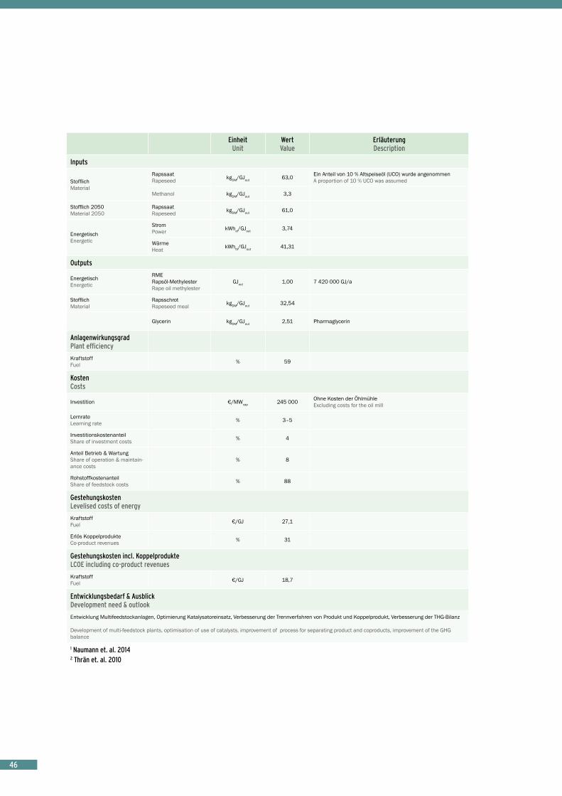
4646
EinheitUnit
Wert Value
Erläuterung Description
Inputs
StofflichMaterial
RapssaatRapeseed kgDM/GJout 63,0 Ein Anteil von 10 % Altspeiseöl (UCO) wurde angenommen
A proportion of 10 % UCO was assumed
Methanol kgDM/GJout 3,3
Stofflich 2050Material 2050
RapssaatRapeseed kgDM/GJout 61,0
EnergetischEnergetic
StromPower kWhel/GJout 3,74
WärmeHeat kWhth/GJout 41,31
Outputs
EnergetischEnergetic
RMERapsöl-MethylesterRape oil methylester
GJout 1,00 7 420 000 GJ/a
StofflichMaterial
Rapsschrot Rapeseed meal kgDM/GJout 32,54
Glycerin kgDM/GJout 2,51 Pharmaglycerin
AnlagenwirkungsgradPlant efficiency
KraftstoffFuel % 59
KostenCosts
Investition €/MWcap 245 000 Ohne Kosten der ÖhlmühleExcluding costs for the oil mill
LernrateLearning rate % 3–5
InvestitionskostenanteilShare of investment costs % 4
Anteil Betrieb & WartungShare of operation & maintain-ance costs
% 8
RohstoffkostenanteilShare of feedstock costs % 88
GestehungskostenLevelised costs of energy
KraftstoffFuel €/GJ 27,1
Erlös KoppelprodukteCo-product revenues % 31
Gestehungskosten incl. KoppelprodukteLCOE including co-product revenues
KraftstoffFuel €/GJ 18,7
Entwicklungsbedarf & AusblickDevelopment need & outlook
Entwicklung Multifeedstockanlagen, Optimierung Katalysatoreinsatz, Verbesserung der Trennverfahren von Produkt und Koppelprodukt, Verbesserung der THG-Bilanz
Development of multi-feedstock plants, optimisation of use of catalysts, improvement of process for separating product and coproducts, improvement of the GHG balance
1 Naumann et. al. 20142 Thrän et. al. 2010

Foto: A. Gröber, DBFZ 47
Die dezentrale Produktion von Biodiesel (engl. fatty acid methyl esters - FAME) aus insbesondere Raps ist Stand der Technik und wurde in Deutschland kommerziell betrieben. Im Unterschied zu zentralen Anlagen ist die Wertschöpfung dabei stärker in regionale Stoffverbünde eingebunden. Eine Vermarktung des Biodiesels ist jedoch bei den kleinen Anlagengrößen nur als Reinkraftstoff sinnvoll. Durch das Wegfallen des Marktes für reinen Biodiesel in Deutschland haben viele dezentrale Anlagen den Betrieb eingestellt.
The decentralised production of biodiesel (FAME - fatty acid methyl esters) from oil-bearing crops (especially rapeseed) is state-of-the-art and is in commercial opera-tion. Contrary to zentralised plants the rapeseed oil can be decentrally provided with high-value animal feed as a by-product. In Germany, small-scale decentralised plants were in operation, but many have now ceased production.
EinheitUnit
Wert Value
Erläuterung Description
Status quo
AnlagenbestandNumber of operating facilities – ca. 50 Biodieselanlagen insgesamt1
Biodiesel plants in total1
Installierte LeistungInstalled capacity GW ca. 5
Gesamt: 4,4 Mio. t/a Produktionskapazität, derzeit nur 2/3 Auslastung, insbesondere dezentrale Anlagen sind nicht mehr im Betrieb oder abgebaut1 Total: 4,4 million t/a production capacity, currently only using 2/3 capacity; in particular, decentralised plants are no longer in operation or are being decommissioned1
NettokraftstoffNet fuel production PJ/a ca. 100
Gesamt: 2,73 Mio. t (2012); Verbrauch geringer als Produktion – Einsatz 2014 in Deutschland gesamt: etwa 1,85 Mio. t.1Total: 2,73 million t (2012); consumption lower than production – total utilisation in Germany in 2014 approx. 1,85 million t.1
ClusterCluster overview
VerfahrenProcess & technology
Umesterung von (Pflanzen)Ölen und Fetten zu Fettsäuremethylestern (FAME/“Biodiesel“) Transesterification of (vegetable) oils and fats to produce fatty acid methyl esters (FAME/”Biodiesel”)
ProzessketteProcess chain
Dezentrale Ölmühle mit mechanischer Ölpressung, Rohölraffination, Umesterung, Glycerinabscheidung und -aufbereitung, Methyles-terwäsche, Methylestertrocknung1 Decentralised oil mill with mechanical oil pressing, crude oil refining, transesterification, glycerol separation and processing, methyl ester washing, methyl ester drying1
LeistungsspektrumPower range
Ca. 500 t/a (Kleinanlagen) bis zu 650 000 t/a (Industrieanlagen)1 Approx. 500 t/a (small-scale plants) up to 650 000 t/a (industrial plants)1
EntwicklungsstandStage of development
Kommerzielle Produktion sowohl in zentralen als auch dezentralen Anlagen1 Commercial production both in centralised and decentralised plants1
Varianz der Technologie Technology variance
Multifeedstock (Deutschland: Rapsöl, Palmöl, Sojaöl, tierische Fette, Altfett)2
Multifeedstocks (Germany: rapeseed oil, Palm oil, soya oil, animal fats, used fat)2
ModellparameterModel parameters
AnlagePlant
Ausstoß Production of Biodiesel GJ/a 1 113 000 ca. 30 000 t/a
Kapazität Capacity Biodiesel MW 36,80
Volllaststunden Full load hours h/a 8 400
LaufzeitLifespan (runtime) a 20
FAME Biodiesel (klein)
FAME Biodiesel (small)

48
EinheitUnit
Wert Value
Erläuterung Description
Inputs
StofflichMaterial
RapssaatRapeseed kgDM/GJout 74,0
Methanol kgDM/GJout 3,3
Stofflich 2050Material 2050
RapssaatRapeseed kgDM/GJout 70,0
EnergetischEnergetic
StromPower kWhel/GJout 1,54
WärmeHeat kWhth/GJout 1,94
Outputs
EnergetischEnergetic
RMERapsöl-MethylesterRape oil methylester
GJout 1,00 1 113 000 GJ/a
StofflichMaterial
Rapspresskuchen Rapeseed cake kgDM/GJout 47,96
Glycerin kgDM/GJout 3,48
AnlagenwirkungsgradPlant efficiency
KraftstoffFuel % 60
KostenCosts
Investition €/MWcap 245 000
LernrateLearning rate % 3–5
InvestitionskostenanteilShare of investment costs % 15
Anteil Betrieb & WartungShare of operation & maintain-ance costs
% 21
RohstoffkostenanteilShare of feedstock costs % 64
GestehungskostenLevelised costs of energy
KraftstoffFuel €/GJ 42,5
Erlös KoppelprodukteCo-product revenues % 25
Gestehungskosten incl. KoppelprodukteLCOE including co-product revenues
KraftstoffFuel €/GJ 31,9
Entwicklungsbedarf & AusblickDevelopment need & outlook
Entwicklung Multifeedstockanlagen, Optimierung Katalysatoreinsatz, Verbesserung der Trennverfahren von Produkt und Koppelprodukt, Verbesserung der THG-Bilanz
Development of multi-feedstock plants, optimisation of use of catalysts, improvement of process for separating product and coproducts, improvement of the GHG balance
1 Naumann et. al. 20142 Thrän et. al. 2010
48

4949
Mit Wasserstoff behandelte biogene Öle (engl.: hydro-treated vegetable oils - HVO) sowie Ester und Fettsäuren (engl.: hydrotreated esters and fatty acids - HEFA) sind am Markt verfügbar und werden auch national im Verkehrs-bereich eingesetzt, jedoch derzeit in Deutschland nicht produziert. Als Produktionsanlagen lassen sich teilweise auch bestehende Raffineriestandorte umrüsten. HVO wird wie Biodiesel dem Dieselkraftstoff beigemischt. Bestim-mte Anteile von HVO können zudem zu Kerosin für den Flugverkehr beigemischt werden.
Hydrotreated vegetable oils (HVO) as well as hydrotreated esters and fatty acids (HEFA) are available on the market and are used in Germany in the transport sector (although they are not produced here). In some cases, existing refinery facilities can be converted into production plants. HVO, like biodiesel, is used as an admixture to diesel fuel. Certain fractions of HVO can furthermore be blended with kerosene for aviation purposes.
EinheitUnit
Wert Value
Erläuterung Description
Status quo
AnlagenbestandNumber of operating facilities – 0
Nur Importe von HVO, weltweit > 10 Anlagen (> 2 Mio. t/a)1 Only imports of HVO, > 10 plants (> 2 million t/a) around the world1
NettokraftstoffNet fuel production PJ/a ca. 21
Ausschließlich Importe; etwa 21 PJ HVO/HEFA Einsatz in Deutschland (2013)1 Imports only; approx. 21 PJ HVO/HEFA used in Germany (2013)1
ClusterCluster overview
VerfahrenProcess & technology
Hydrodesulfierung, Rektifikation von raffinierten (Pflanzen)Ölen und Fetten zu HVO/HEFA-Diesel hoher Reinheit Hydro-desulphurisation, rectification of refined (vegetable) oils and fats to produce high-purity HVO/HEFA-diesel
ProzessketteProcess chain
Ölmühle, Rohölraffination, Hydrotreating, Rektifikation; Stand-Alone-Anlagen oder Co-Processing in bestehenden Raffinerien möglich2 Oil mill, crude oil refining, hydro-treating, rectification; stand-alone plants or co-processing in existing refineries possible2
LeistungsspektrumPower range
170 000–800 000 t/a Gesamtprodukte2 170 000–800 000 t/a total products2
EntwicklungsstandStage of development
Kommerzielle Anlagen in Betrieb, Demonstrationsanlagen in Europa in DE, DK, IT und ES2 Commercial plants in operation, demonstration plants in Europe in Germany, Denmark, Italy and Spain2
Varianz der Technologie Technology variance
Multifeedstock (Rapsöl, Palmöl, Sojaöl, tierische Fette, Altfett, Tallöl, Algenöl, Pyrolyseöl), Diesel-, Kerosin- und Ottokraftstoffe zur Nutzung in Straßenverkehr, Luft- und Schifffahrt2 Multifeedstocks (rapeseed oil, palm oil, soya oil, animal fats, used fat, tall oil, algal oil, pyrolytic oil), diesel, kerosene and petrol for use in road, air and marine transport2
ModellparameterModel parameters
AnlagePlant
Ausstoß Production of HVO GJ/a 8 820 000
Kapazität Capacity HVO MW 292
Volllaststunden Full load hours h/a 8 400
LaufzeitLifespan (runtime) a 20
HVO / HEFA HVO / HEFA
Foto: Rainer Sturm_pixelio.de

50
EinheitUnit
Wert Value
Erläuterung Description
Inputs
StofflichMaterial
RapssaatRapeseed kgDM/GJout 65,0
WasserstoffHydrogen kgDM/GJout 1,0
EnergetischEnergetic
StromPower kWhel/GJout 7,1
WärmeHeat kWhth/GJout 30,8
Outputs
EnergetischEnergetic HVO GJout 1,00 8 820 000 GJ/a
StofflichMaterial
Brenngase (Butan, Propan) Fuel gases (butane, propane)
kg/GJout 1,64
Kraftstoffe, NaphthaFuels, naphta kg/GJout 0,57
AnlagenwirkungsgradPlant efficiency
KraftstoffFuel % 58
KostenCosts
Investition €/MWcap 780 000
LernrateLearning rate % 2–5
InvestitionskostenanteilShare of investment costs % 5
Anteil Betrieb & WartungShare of operation & maintain-ance costs
% 10
RohstoffkostenanteilShare of feedstock costs % 84
GestehungskostenLevelised costs of energy
KraftstoffFuel €/GJ 33,8
Erlös KoppelprodukteCo-product revenues % 21
Gestehungskosten incl. KoppelprodukteLCOE including co-product revenues
KraftstoffFuel €/GJ 26,8
Entwicklungsbedarf & AusblickDevelopment need & outlook
Erweiterung der Rohstoffbasis mit HEFA (z.B. Tallöl, Algenöl, Pyrolyseöl), Prozessoptimierung hinsichtlich Netto-Wasserstoffverbrauch
Expansion of the feedstock basis with HEFA (e.g. tall oil, algal oil, pyrolytic oil), process optimisation as regards net hydrogen consumption
1 Naumann/Müller-Langer 2015 (Vortrag/presentation)2 Naumann et al. 2014
Foto: Rolf Handke_pixelio.de
50

5151
Verbrennung
Combustion
Foto: Janusz Klosowski_pixelio.de

525252
Einzelraumfeuerung Single room heater
In Germany there are around 12 to14 million single-room combustion units (not including boilers) which account for a significant proportion of the consumption of wood in Germany and which contribute around one third to the utilisation of thermal energy produced from rene-wables in Germany. There are numerous different types of single-room combustion units, which are subdivided according to the First Ordinance on the Implementation of the Federal Emission Control Act (1. BImSchV) into various systems (e.g. room heaters, storage single-room combustion units, fireplace inserts, tiled stove inserts, cooking stoves, heating stoves). These single-room combustion units are characterised – with few exceptions – by electricity-free operation (the air supply is not electro-nically controlled and is influenced only by adjusting a vent and by the natural chimney effect). Combustion takes place almost exclusively in a bed of glowing embers burning upwards. In a flat-grate type firing system, only a comparatively small amount of fuel is placed on the grate and fuel is added regularly at intervals of around 15 to 60 minutes. In top-feed burner units, only one charge of wood is fed in for one combustion phase, which then burns down completely during a period of more than an hour. The heat is usually stored in a solid storage material and then released into the room over a period of 12 to 24 hours. This results in different emissions trajectories. Flat-grate type firing systems tend to dominate on the market, although particularly older houses contain a significant number of top-feed burner units. The size of the combus-tion units is typically between 4 and 16 kW. For single-room combustion log burners, a minimum appliance efficiency of 70 to 80 %, depending on construction type, compared with test bench measurements in „optimum“ operation, has been required since 22 March 2010 under the First Ordinance on the Implementation of the Federal Emission Control Act (1. BImSchV). In proper operation, new systems should reach an efficiency of around 85 % in practice.Overall, faulty operation leading to the cooling of excessively produced heat and resulting from the fact that most single-room combustion units are not leakproof, means that there is constant additional loss of heat in the room, so that the efficiency of existing units can be assumed to be about 65 %.
In Deutschland gibt es ca. 12 bis 14 Millionen Einzel-raumfeuerstätten (ohne Kessel), die einen beträchtlichen Anteil des Verbrauches an Holz in Deutschland ausma-chen und zu gut einem Drittel der erneuerbaren Wärme in Deutschland beitragen. Es gibt eine Vielzahl verschie-dener Typen von Einzelraumfeuerungen, welche gemäß 1. BImSchV in verschiedene Systeme (z. B. Raumheizer, Speichereinzelfeuerstätten, Kamineinsätze, Kachelofen-einsätze, Herde, Heizungsherde) unterteilt werden. Die Einzelraumfeuerungen zeichnen sich – bis auf wenige Ausnahmen – durch einen stromunabhängigen Betrieb aus (Luftzufuhr ist nicht elektronisch geregelt und wird allein durch Klappenstellungen und den natürlichen Schornsteinzug) beeinflusst. Die Verbrennung findet fast ausschließlich in einer Glutbettauflage nach oben statt. Bei der Flachfeuerung wird nur eine vergleichsweise kleine Brennstoffmenge aufgelegt und in regelmäßi-gen Abständen von 15 bis 60 Minuten wird Brennstoff nachgelegt. Bei der Füllfeuerung wird meist für eine Brandphase nur einmal Holz eingelegt und dann komplett über mehr als eine Stunde verbrannt. Die Wärme wird i.R. in massivem Speichermaterial gespeichert und dann über 12 bis 24 Stunden an den Raum abgegeben. Entsprechend ergeben sich unterschiedliche Emissions-verläufe. Tendenziell sollten die Flachfeuerungen am Markt überwiegen, wobei gerade in älteren Häusern auch nennenswerte Zahlen an Füllfeuerungen vorhanden sind. Die Größe der Feuerungen liegt typischerweise bei 4 bis 16 kW. Die Geräteeffizienz ist in Bezug auf Prüfstands-messungen im „optimalen“ Betrieb gemäß 1. BImSchV für Scheitholzeinzelraumfeuerungen mit Mindestwerten von 70 bis 80 % je nach Bauart seit 22.03.2010 vorge-schrieben. Neue Systeme sollten bei richtigem Betrieb in der Praxis etwa 85 % an Effizienz erreichen. In der Summe der Betriebsfehler bis hin zum Wegkühlen zu viel produzierter Wärme und der Undichtigkeit der meisten Einzelraumfeuerungen, die zu einem dauerhaften zusätz-lichen Wärmeverlust im Raum führen, ist im Bestand von einer Effizienz von 65 % auszugehen.

53Foto: Rainer Sturm_pixelio.de 53
EinheitUnit
Wert Value
Erläuterung Description
Status quo
AnlagenbestandNumber of operating facilities GW ca. 115
Holzverbrauch (i. d. R. Scheitholz) von ca. 14 Mio tatro pro Jahr in Deutschland1
Wood consumption (usually logs) of approximately 14 million tatro per annum in Germany1
NettowärmeNet heat production PJ/a ca. 250 Stark schwankend je nach Winterwitterung2
Fluctuates strongly depending on weather conditions in winter2
ClusterCluster overview
VerfahrenProcess & technology
Verbrennung lufttrockener Holzscheite in einem Kaminofen zur temporären Einzelraumbeheizung aus Behaglichkeitsgründen (Statussymbol) oder KostengründenCombustion of air-dry logs in a wood burner for temporary single-room heating for reasons of comfort (status symbol) or costs
ProzessketteProcess chain
Verbrennung von Holzscheiten unter ungeregelten verfahrenstechnischen Parametern3 Combustion of logs under unregulated process parameters3
LeistungsspektrumPower range 4–16 kW
EntwicklungsstandStage of development
Verbreitete und anspruchslose Technologie3 Widespread and simple technology3
Varianz der Technologie Technology variance
Einfache Rostfeuerung mit hoher Brennstoffvarianz, hohe Vielfalt an Systemen: Kamine, Öfen, Heizeinsätze, Kachelöfen3 Simple grate firing with wide variety of solid fuels and diversity of systems: fireplaces, ovens, heating inserts, tiled stoves3
ModellparameterModel parameters
AnlagePlant
Ausstoß Production of
WärmeHeat GJ/a 11,5
Kapazität Capacity MW 0,008
Volllaststunden Full load hours h/a 400 Sehr abhängig vom Nutzerverhalten
Highly dependent on user behaviour
LaufzeitLifespan (runtime) a 15
Einige Einzelraumfeuerungssysteme haben eine Lebensdauer von bis zu 25 Jahren, in Einzelfällen bis zu 40 JahrenSome single-room combustion systems have a service life of up to 25 years, occasionally up to 40 years
Inputs
StofflichMaterial
ScheitholzLong wood kgDM/GJout 85,0
Ca. 1tatro/a (entspricht nach DEPV dem durchschnittlichen Brennstoffeinsatz je Einzelraumfeuerung in Deutschland)Approx. 1 tatro/a (according to the DEPV, this corresponds to the average consumption of solid fuel per single-room combustion unit in Germany)
Stofflich 2050Material 2050
ScheitholzLong wood kgDM/GJout 65,0

54
EinheitUnit
Wert Value
Erläuterung Description
Outputs
StofflichMaterial
Asche (Rostasche)Ash (grate ash) kg/GJout 0,85
Entsorgung in der Regel über Restmülltonne; bei Einhaltung der Vorschriften als Dünger einsetzbar Disposal usually as residual household waste; usable as ferti-liser provided regulations are adhered to
EnergetischEnergetic
WärmeHeat GJ/GJout 1,00
AnlagenwirkungsgradPlant efficiency
ThermischThermal % 65
Ca. 65 % im Bestand; technisch bis zu 85 % möglichApprox. 65 % for existing units; up to 85 % technically possible
KostenCosts
Investition €/MWcap 200 000
Wenn Schornstein vorhanden; große Bandbreiten von Markt-preisen: 50 bis zu 1 000 €/kW (typischerweise 100–500 €/kW); kaum Kostensenkungen, aufgrund steigender Umweltanforderungen If chimney exists; wide range of market prices: € 50 up to 1 000/kW (typically € 100–500/kW); cost reduction hardly possible owing to increasingly strict environmental regulations
LernrateLearning rate % 0
InvestitionskostenanteilShare of investment costs % 55
Anteil Betrieb & WartungShare of operation & maintain-ance costs
% 5
RohstoffkostenanteilShare of feedstock costs % 40
GestehungskostenLevelised costs of energy
ThermischThermal €/GJ 31,0
Erlös KoppelprodukteCo-product revenues % 0
Gestehungskosten incl. KoppelprodukteLCOE including co-product revenues
ThermischThermal €/GJ 31,0
Entwicklungsbedarf & AusblickDevelopment need & outlook
Zunehmend erfolgt eine Integration der Anlagen in das thermische Energiekonzept (Warmwasserbereitung, Heizungssystem) des Hauses. Die weitere Verbesserung der Emissionsminderung (Feinstaub) ist aufgrund steigender Anforderungen notwendig. Bei Technologiesprüngen in der Vergasungstechnologie könnte diese auch zu einem Upgrade der reinen Wärmebereitstellung im kleinen Leistungsbereich beitragen. Einzelraumfeuerung auf der Basis von (Scheit-)Holz werden weiterhin eine Relevanz behalten aufgrund des damit einhergehenden Behaglichkeitsgefühls und dem relativ einfachen Brennstoffzugang aufgrund des kleinteiligen Waldbesitzes in Deutschland. Die Zahl thermisch isolierter Häuser und Gebäude mit kontrollierter Belüftung wird signifikant zunehmen. Für diese Gebäude werden Heizsysteme mit niedriger thermischer Kapazität und entsprechender Frischluftzufuhr benötigt. Daher wird sich die Anzahl von Einzelraumfeuerungen über 7 kW verringern und neue Holzheizsysteme (geringere Kapazitäten um 2 kW; Systeme mit z. B. Gegenstromvergasung und längeren Verbrennungsvorgang; häufig Anschluss an das Warmwasser- und Heizungssystem mittels Wärmetauscher) werden auf den Markt kommen.
Increasingly, integration of plants into the thermal energy concept (hot water supply, heating system) of the house. Further improvement of emission reductions (particulates) is necessary owing to stricter regulations. If technology leaps take place in gasification technology, these could also contribute to an upgrade of heat-only supply in the small-scale capacity range. Wood log stoves will retain some relevance because of small scale forest ownership and people’s ongoing affection for having their own fire and fuel control. The number of well-insulated buildings and housing with controlled air circulation will increase significantly. Therefore in these buildings the stoves will need lower thermal output capacity and a specially defined fresh air inlet. The number of wood log stoves with more than 7 kW will decrease; newly developed wood log stoves will come onto the market (low capacity of about 2 kW; downdraft or sidedraft combustion with pre-gasification and combustion time for each period of about 2 to 4 hours and connection to central heating system by heat exchanger to water cycle).
1 DBFZ-eigene Berechnung (DBFZ own assumptions) / Annahmen basierend auf Lenz, V. (2014): Meilensteine 2030 – Perspektiven der Biomasse im Wärmesektor – Teil 2. Workshop „Biomasse im Wärmemarkt der Zukunft“, 18.02.2014, Frankfurt am Main.2 BMWi (2015)3 Thrän et al. (2010)

55
Pelletkessel werden i. d. R. als monovalente Heizsys-teme eingesetzt, da sie gut in ihrer Leistung regelbar sind und mittels Heißluftgebläse auch gut automatisch zünden können. Die Geräteeffizienz ist in Bezug auf Prüfstandsmessungen im „optimalen“ Betrieb im Bereich von 90–94 % (Wirkungsgrad). Hierbei wird ein nahezu vollständiger Ausbrand bei extrem niedrigen Emissionen erreicht und die produzierte Wärme wird weitgehend vollständig vom Wärmesystem abgenommen. In realen Praxisanlagen sinken die Nutzungsgrade aufgrund von An- und Abfahrprozessen, Auskühlverlusten, Verlusten an Unverbranntem in der Asche und erhöhten Strombedarfe zum Teil deutlich. U. a. können unzureichende Rege-lungsstrategien z. B. im Zusammenspiel mit Puffern und Solaranlagen erhebliche zusätzliche Wärmeverluste gene-rieren, so dass Jahresnutzungsgrade bis auf 67 % sinken können. Der DEPV (2013) geht von einem durchschnitt-lichen Nutzungsgrad von 83 % aus. Eigene Erhebungen und Daten von Schraube et al. 2010 und Kunde et al. 2010 zeigen durchschnittliche Jahresnutzungsgrade von rund 74 % mit Bestwerten bei ca. 85 % bezogen auf den Gesamtenergieeinsatz aus Brennstoff und Hilfsenergie. Insofern ist mit besseren Installationsregeln und opti-mierten Systemreglern eine Effizienzverbesserung von ca. 0,1 % pro Jahr zu rechnen.
Pellet fired boilers are generally used as monovalent heating systems since their output can be easily regulated and they can be automatically ignited by means of a hot-air blower. Compared with test bench measurements with „optimum“ operating conditions, the efficiency of the appliance is in the range between 90 and 94 % (efficiency). Under these conditions, almost complete burnout is achieved with extremely low emissions, and the heat produced is almost completely taken up by the heating system. In real practice, the efficiency levels decrease sometimes significantly, owing to start-up and shutdown processes, cooling losses, unburned materials in the ash and increased electricity requirements. Among other things, insufficient regulation strategies, e.g. in the interaction with buffers and solar systems, can lead to considerable additional losses of heat, so that annual efficiencies can fall to 67 %. The DEPV (2013) assumes an average efficiency of 83 %. Our own surveys and data provided by Schraube et al. 2010 and Kunde at al. 2010 show average annual efficiencies of around 74 % with top values of around 85 % in relation to the overall energy input of solid fuel and auxiliary energy. It can therefore be assumed that improved installation rules and optimised system regulators would lead to an improvement in effici-ency of approximately 0,1 % p.a..
Pelletkessel < 300 kW Wood pellet stove < 300 kW
EinheitUnit
Wert Value
Erläuterung Description
Status quo
AnlagenbestandNumber of operating facilities – 195 000 2012
Installierte LeistungInstalled capacity GW 5,60
Jahresverbrauch von rund 1,7 Mio t (2012) fast ausschließlich in Pelletkesseln und zu etwa 4 % in PelletöfenAnnual consumption of around 1,7 million t (2012) almost exclusively in pellet fired boilers, with around 4 % in pellet stoves
NettowärmeNet heat production PJ/a ca. 30 Mit wachsender Tendenz
Tendency: growing
ClusterCluster overview
VerfahrenProcess & technology
Pyrolytische Vergasung und Verbrennung normierter Holzpellets (A1-Holz; zumeist Sägewerksnebenprodukte und Waldstammholz) als Kesselfeuerung in Mehr- und Einfamilienhäusern sowie dezentralen KleinanlagenPyrolytic gasification and combustion of standardised wood pellets (A1 wood; mostly sawmill co-products and forest trunk wood) fired in boilers in individual houses and apartment buildings as well as decentralised small-scale plants
ProzessketteProcess chain
Pyrolytische Vergasung der Holzpellets, Verbrennung der Produktgase in Brennkammer unter kontrollierten feuerungstech. Bedin-gungen, Wärmetauscher zur WassererwärmungPyrolytic gasification of wood pellets, combustion of product gases in a combustion chamber under controlled firing conditions, heat exchanger for hot water supply
LeistungsspektrumPower range
10–300 kW; bei Systemen < 50 kW zumeist 15 kW im Leistungsbereich > 50 kW typisch 220 kW , meist monovalenter Einsatz durch gute Regelbarkeit 10–300 kW; in systems of < 50 kW mostly 15 kW; in the capacity range > 50 kW typically 220 kW , mostly monovalent use owing to good adjustability
EntwicklungsstandStage of development
Ausgereifte und marktetablierte Technologie mit geringen OptimierungspotenzialenMature technology that is well established on the market and has little potential for optimisation
Varianz der Technologie Technology variance
Geringe Varianz, Holzpellets nach DIN EN 14961-2Little variance, wood pellets in accordance with the standard DIN EN 14961-2
ModellparameterModel parameters
AnlagePlant
Ausstoß Production of
WärmeHeat GJ/a 86,4
Kapazität Capacity MW 0,015
Volllaststunden Full load hours h/a 1 600
LaufzeitLifespan (runtime) a 15

56
EinheitUnit
Wert Value
Erläuterung Description
Inputs
StofflichMaterial
HolzpelletsWood pellets kgDM/GJout 75,0
Entspricht 74 % bei Heizwert von 18 MJ/kgCorresponds to 74 % with a lower heating value of 18 MJ/kg
Stofflich 2050Material 2050
HolzpelletsWood pellets kgDM/GJout 60,5
Entspricht 74 % bei Heizwert von 18 MJ/kgCorresponds to 74 % with a lower heating value of 18 MJ/kg
EnergetischEnergetic
StromPower kWhel/GJout 3,5
Stromaufnahme bei 1 % bis 2 (bis zu 5 %) des Gesamtener-gieinputsElectricity input 1 % to 2 % (up to 5 %) of total energy input
Outputs
StofflichMaterial
Asche (Rostasche)Ash (grate ash) kg/GJout 0,40
Entsorgung in der Regel über Restmülltonne; bei Einhaltung der Vorschriften als Dünger einsetzbar Disposal usually as residual household waste; usable as ferti-liser provided regulations are adhered to
EnergetischEnergetic
WärmeHeat GJ/GJout 1,00
AnlagenwirkungsgradPlant efficiency
ThermischThermal % 83
KostenCosts
Investition €/MWcap 100 000
Mit allen Installationen ca. 1 800 €/kW; je nach Hersteller und Produktqualitätssegment: 500–1 500 €/kW (für Kessel im 15 kW-Bereich liegen nur für den Kessel die spezifischen Kosten bei 300–1 100 €/kW, womit sich dann Gesamtkosten von ca. 1 000 bis 2 800 €/kW ergeben. Bei über 100 kW liegen die Kesselkosten bei rund 200 €/kW und installiert im System bei ca. 400–500 €/kW) With all installations approx. 1 800 €/kW; depending on manufacturer and product quality segment: € 500–1 500/kW (for boilers in the 15 kW range, the specific costs for the boiler alone are between € 300 and € 1 100/kW, resulting in total costs of around € 1 000–€ 2 800/kW. In plants with > 100 kW, the boiler costs are around € 200 /kW and installed in the system around € 400–500/kW.)
LernrateLearning rate % 5–8
InvestitionskostenanteilShare of investment costs % 47
Anteil Betrieb & WartungShare of operation & maintain-ance costs
% 8
RohstoffkostenanteilShare of feedstock costs % 45
GestehungskostenLevelised costs of energy
ThermischThermal €/GJ 39,0 Bei 230 €/t Pellets
At € 230 /t of pellets
Erlös KoppelprodukteCo-product revenues % 0
Gestehungskosten incl. KoppelprodukteLCOE including co-product revenues
ThermischThermal €/GJ 39,0
Entwicklungsbedarf & AusblickDevelopment need & outlook
Intelligente Steuerung und Integration in Systemverbund; als mögliche Technologieerweiterung in Richtung stromerzeugende Wärmeanlage sind Mikro-KWK (z. B. Stirling) denkbar, jedoch aufgrund technischer Herausforderungen perspektivisch eher Kleinvergasung
Intelligent control and integration in a system; a possible technological development moving towards electricity generating heating plants might be micro-CHP units (e.g. Stirling), but the technical challenges mean that small-scale gasifiers have better prospects
56

5757
Foto: Morlok_pixelio.de
57
Holzhackschnitzelkessel sind Stand der Technik und zumeist im mittleren Leistungsspektrum vertreten. Die Anlagenkonfigurierung (Größe, Grundlast oder Spitzen-last) hängt von dem konkret mit Wärme zu versorgenden Objekt ab. In dieser Größenordnung werden HHS-Kessel zumeist in einem bivalenten Wärmeverbund mit einem Öl- oder Gasspitzenlastkessel betrieben, so dass die Jahresnutzungsgrade tendenziell bei etwa 75 bis 80 % liegen können.
Woodchip heating plants are state-of-the-art and are mostly to be found in the medium capacity range. The plant configuration (size, base load or peak load) depends on the specific building that is to be supplied with heat. In this size range, woodchip heating plants are mostly operated in a bivalent heating system combined with an oil or gas-fired peak-load heating plant so that the annual efficiencies tend to be around 75–80 %.
Holzhackschnitzelkessel > 300 kW–2 MW
Wood chip heating plant > 300 kW–2 MW
EinheitUnit
Wert Value
Erläuterung Description
Status quo
AnlagenbestandNumber of operating facilities –
Wenige Tausend1 Several
Thousand1
Installierte LeistungInstalled capacity GW ca. 3–61,2 Einsatzmengen ca. 5–6 Mio. tatro
Input quantities approx. 5–6 million tatro
NettowärmeNet heat production PJ/a ca. 402
ClusterCluster overview
VerfahrenProcess & technology
Verbrennung von HHS unterschiedlicher Qualitäten durch gesteuerte Rostfeuerung oder Unterschubfeuerungen in automatischen Kleinfeuerungskesselanlagen in zumeist bivalentem Betrieb (d. h. gekoppelt mit einer zweiten Kesselanlage, z. B. für Gas oder Öl) Combustion of wood chips of varying quality by means of controlled grate firing or underfeed firing in automatic small-scale heating plants, mostly in bivalent operation (i.e. coupled with a second heating plant, e.g. for gas or oil)
ProzessketteProcess chain
Verbrennung von HHS in Rostfeuerung mit automatisierter Steuerungstechnik, Wärmeübergang an Wärmetauschern, Rauchgas-reinigung, Wärmebereitstellung für Unternehmen, öffentliche Gebäude oder Wohngebäuden; zur Reduzierung von Taktzeiten und Netzverlusten wird die Nutzenergie gewöhnlich in Wärmespeichern zwischengespeichert, derzeit üblicherweise kurzfristig (max. 24 Stunden) in wasserbasierten SpeichernCombustion of wood chips by means of grate firing with automated control technology, thermal transfer to heat exchangers, flue gas purification, heat supplies to businesses, public buildings or residential buildings; for reducing cycle times and network losses, the useful energy is usually temporarily stored in heat accumulators, at present usually for a short period (up to 24 hours) in water-based storage systems
LeistungsspektrumPower range
30–2 000 kW bis zu mehreren MW (typisch 300–1 000 kW), es gibt einige HHS-Kessel die in sehr kleinen Leistungsbereichen ab 30 kW vor allem auch monovalent eingesetzt werden30–2 000 kW up to several MW (typically 300–1 000 kW); there are some woodchip heating plants which can be used in very small-scale capacity ranges starting at 30 kW, most of which are monovalent
EntwicklungsstandStage of development
Ausgereifte und marktetablierte Technologie, in diesem Leistungsbereich eine der wenigen erneuerbaren Wärmebereitstellungsop-tionMature technology which is established on the market; in this capacity range, one of the few renewable heat supply options
Varianz der Technologie Technology variance
Hohe Varianz der Brennstoffparameter durch flexible TechnologieHigh degree of variation in the fuel parameters owing to flexible technology
ModellparameterModel parameters
AnlagePlant
Ausstoß Production of
WärmeHeat GJ/a 9 000
Kapazität Capacity MW 0,50
Volllaststunden Full load hours h/a 5 000
LaufzeitLifespan (runtime) a 20

585858
EinheitUnit
Wert Value
Erläuterung Description
Inputs
StofflichMaterial
HolzhackschnitzelWood chip
kgDM/GJout 71,0
Bivalente HHS-Kessel laufen im Schnitt wahrscheinlich etwas besser als die Pelletkessel bei Nutzungsgrad von 78 %. In Zukunft nehmen die Netzverluste zu, so dass sich die Relation zu Pelletkesseln verschieben kann.Bivalent wood pellet boilers run on average probably slightly better than the pellet boiler in an efficiency of 78 %.In future the network losses will increase, so that their efficiency in relation to pellet fired plants may change.
Stofflich 2050Material 2050
HolzhackschnitzelWood chip kgDM/GJout 65,0
EnergetischEnergetic
StromPower kWhel/GJout 5,6
Ca. 1–3 % produzierte Wärme in einer kWHelAbout 1 to 3 % of produced heat in kWhel
Outputs
StofflichMaterial
Asche (Rostasche)Ash (grate ash) kg/GJout 1,00
Entsorgung in der Regel über Restmülltonne; bei Einhaltung der Vorschriften als Dünger einsetzbarDisposable usually in household waste bins; usable as fertiliser provided regulations are adhered to
EnergetischEnergetic
WärmeHeat GJ/GJout 1,00
AnlagenwirkungsgradPlant efficiency
ThermischThermal % 75
Perspektivisch steigerbar auf 85 %; Kesselwirkungsgrade von bis zu 90 %; Jahresnutzungsgrad in der Praxis entscheidend da z. B. Auskühlverluste beim Taktbetrieb, Verluste durch unvoll-ständige VerbrennungCould potentially be increased to 85 %; heating plant efficien-cies of up to 90 %; annual efficiency in practice is decisive, owing, for example, to cooling losses in cycle operation and losses through incomplete combustion
KostenCosts
Investition €/MWcap 1 500 000
Große Bandbreite je nach Auslegung (Kesselgröße, Anforderun-gen für die Peripherie); hinzu kommt ein fossiler Spitzenlastkes-sel; inkl. Gebäudeneubau und Wärmenetz bis zu 2 000 €/kW Wide range depending on design (plant size, peripheral require-ments); an additional fossil fuel peak-load heating plant is also needed; including new building and heating networks, up to € 2 000 /kW
LernrateLearning rate % 5
InvestitionskostenanteilShare of investment costs % 45
Anteil Betrieb & WartungShare of operation & maintain-ance costs
% 25
RohstoffkostenanteilShare of feedstock costs % 30
GestehungskostenLevelised cost of energy
ThermischThermal €/GJ 24,0
Erlös KoppelprodukteCo-product revenues % 0
Gestehungskosten incl. KoppelprodukteCosts including co-product revenues
ThermischThermal €/GJ 24,0
Entwicklungsbedarf & AusblickDevelopment need & outlook
Verbesserung der Nutzungsgrade könnte bei kleineren Leistungen durch eine verbesserte Auslegung und Systemintegration möglich sein. Bei größeren Leistungen bzw. zukünftigen Technologiesprüngen (Vergasungstechnologie) sind KWK-Systeme aus Effizienzgründen vorzuziehen.
Improvement of efficiencies may be possible in smaller capacity plants by means of improved design and system integration. In larger capacity plants or with future technology leaps (gasification technology), CHP systems are preferable for reasons of efficiency.
1 DBFZ-eigene Berechnung/Annahmen basierend auf (calculations/assumptions based on) Lenz, V. (2014): Meilensteine 2030 – Perspektiven der Biomasse im Wärmesektor – Teil 2. Workshop „Biomasse im Wärmemarkt der Zukunft“, 18. Februar 2014, Frankfurt am Main2 BMWi (2015)

59
Mikro-KWK-Anlagen werden aufgrund der hohen Gesamt-wirkungsgrade in der Regel im häuslichen oder (klein-)gewerblichen Bereich eingesetzt. Aufgrund der geringen Leistungsgröße ist hier im Wesentlichen von Pellets als Brennstoff auszugehen. Es gibt einige Anbieter von Mikro-KWK-Systemen. Im Leistungsbereich um 1 kWel gibt es derzeit v. a. Dampfkolbenmotoren und Stirling-Motoren in Verbindung mit einer Biomasseverbrennung. Diese Systeme, auch stromerzeugende Heizung genannt, sind technologisch aufwendig und derzeit wirtschaftlich nur wenig attraktiv. Für Leistungen ab 50 kWel aufwärts gibt es auch einige Anwender für Stirling-Motoren, jedoch sind auch hier die elektrischen Nutzungsgrade mit 12 bis 15 % niedrig. An dieser Stelle wird nur die Stirling-Technologie betrachtet. Der Stirlingmotor als die bekannteste Techno-logie ist als Heizkraftblock kommerziell erhältlich. Weitere existierende Technologien im Bereich bis 200 kWel sind Dampfmotoren und -turbinen (so sind beispielsweise Dampfturbinen mit 75 kWel erhältlich). Ob sich die Stirling-Technologie am Markt durchsetzen wird, ist nur schwer einzuschätzen. Die elektrischen Nutzungsgrade sind tendenziell wahrscheinlich nur auf bis zu 20 % steigerbar. Damit erfüllt die Technologie nicht die zukünftigen KWK-Anforderungen. Vergasungsbasierte Mikro-KWK-Anlagen werden auf S. 68 behandelt.
Owing to their high overall efficiencies, micro-CHP plants are generally used in the domestic or (small-scale) commercial sphere. Owing to their small capacity, pellets are generally assumed to be the fuel. There are a few manufacturers offering micro-CHP systems. In the capacity range around 1 kWel there are at present mainly reciprocating engines and Stirling engines combined with a biomass combustion plant. These systems, which are also called electricity-generating heaters, are techni-cally complex and are not very attractive in economic terms. For capacities upwards of 50 kWel there are also some applications for Stirling engines, but here, too, the electrical efficiencies are low at 12 to 15 %. Here, only the Stirling technology has been taken into account, since it is the best-known technology. The Stirling engine is commer-cially available as a cogeneration block. Other existing technologies in the range up to 200 kWel are steam engines and turbines (for example, steam turbines are available with 75 kWel). Whether the Stirling technology will become established on the market is difficult to judge. The electrical efficiencies can probably only be increased to about 20 %. Therefore, this technology will not meet future CHP requirements. Gasification based micro-CHP plants will be dealt with on page 68.
Mikro-KWK (KWK < 100 kWel)
Micro-CHP (CHP < 100 kWel)
EinheitUnit
Wert Value
Erläuterung Description
Status quo
AnlagenbestandNumber of operating facilities –
Mehrere Prototypen verfügbar und im Testbetrieb; ein Massen-markt fehlt bislang; installierte Anlagen (Stirling) zumeist erdgasbasiertSeveral prototypes available and in test operation; so far, there is no mass market; installed plants (Stirling) are mostly natural gas-based
Installierte LeistungInstalled capacity GW < 0,0003 GW
NettostromNet power production PJ/a < 0,002
NettowärmeNet heat production PJ/a < 0,009
ClusterCluster overview
VerfahrenProcess & technology
Mikro-KWK-Anlage auf der Basis eines Pelletkessels in Verbindung mit einem Stirling-Motor Micro-CHP plant on the basis of a pellet fired heating plant in combination with a Stirling engine
ProzessketteProcess chain
Pyrolytische Vergasung der Holzpellets, Verbrennung der Produktgase in Brennkammer unter kontrollierten feuerungstechnischen Bedingungen, Übertragung der Wärme zur Stromerzeugung über eine Stirling-Einheit (ggfs. auch bzw. Stromerzeugung mit Dampf-motor nach Wärmeübertragung in Verdampfer) Pyrolytic gasification of wood pellets, combustion of the product gases in a furnace under controlled firing conditions, transfer of heat for energy generation via a Stirling unit (where necessary, all electricity generation by means of a steam engine following thermal transfer to an evaporator)
LeistungsspektrumPower range
Ca. 1–50 kWel, wird auch als KWK-Kleinstanlage oder Mini-KWK-Anlage bezeichnet; Anlagen < 2,5 kWel werden auch als Nano-KWK bezeichnet, Anlagen > 2,5 kWel bis ca. 20 kWel als Mikro-KWK Approx. 1–50 kWel, also known as mini-CHP system; plants < 2,5 kWel are also referred to as nano-CHP systems, plants > 2,5 kWel up to approx. 20 kWel as micro-CHP systems
EntwicklungsstandStage of development
Die Verbrennung in Anlagen mit kleiner Leistung wird als mäßig flexibel betrachtet, hier ist jedoch mit Verbesserungen im Rahmen der allgemeinen Entwicklung von Biomassefeuerungen sehr kleiner Leistung (wie sie beispielsweise für Niedrigenergiehäuser benö-tigt werden) auszugehen. Die Stromerzeugung mittels Stirling-Einheit wird, gerade in Mikro-KWK-Anlagen, als flexibel eingeschätzt. Combustion in plants with small capacities is regarded as only moderately flexible, but it is to be expected that there will be improve-ments as part of the general development of biomass firing plants of very small capacity (such as those required for low-energy houses). Electricity generation using a Stirling unit is considered flexible, particularly in micro-CHP systems.
Varianz der Technologie Technology variance
Je nach Auslegung neben Stirling-Motor auch Dampfmotor möglich Depending on design, a steam engine is also possible in addition to a Stirling engine
59

60
EinheitUnit
Wert Value
Erläuterung Description
ModellparameterModel parameters
AnlagePlant
Ausstoß Production of
StromPower GJ/a 17,28
Kapazität Capacity MW 0,003 Stirling-Motor
Stirling engine
Volllaststunden Full load hours h/a 1 800
LaufzeitLifespan (runtime) a 15
Inputs
StofflichMaterial
HolzpelletsWood pellets kgDM/GJout 425 Elektrischer Wirkungsgrad 13 %
Electrical efficiency 13 %
Stofflich 2050Material 2050
HolzpelletsWood pellets kgDM/GJout 280 Elektrischer Wirkungsgrad 20 %
Electrical efficiency 20 %
EnergetischEnergetic
StromPower kWhel/GJout 5 1–3 %
Outputs
StofflichMaterial
Asche (Rostasche)Ash (grate ash) kg/GJout 2,5
Entsorgung in der Regel über Restmülltonne; bei Einhaltung der Vorschriften als Dünger einsetzbarDisposable usually in household waste bins; usable as fertiliser provided regulations are adhered to
EnergetischEnergetic
WärmeHeat GJ/GJout 4,0
StromPower GJ/GJout 1,0
AnlagenwirkungsgradPlant efficiency
ElektrischElectric % 13 10–15 %, perspektivisch auf 20 % steigerbar
10–15 %, could be improved to 20 % in future
ThermischThermal % 60
KostenCosts
Investition €/MWcap 10 000 000
LernrateLearning rate % 5 - 10
InvestitionskostenanteilShare of investment costs % 63
Anteil Betrieb & WartungShare of operation & maintain-ance costs
% 7
RohstoffkostenanteilShare of feedstock costs % 30
GestehungskostenLevelised costs of energy
ThermischThermal €/GJ 285,00 Ca. 1 €/kWhel
Approx. € 1 /kWhel
Erlös KoppelprodukteCo-product revenues % bis ca. 35 Bei 0,12 €/kWh
At € 0,12 /kWh
Gestehungskosten incl. KoppelprodukteLCOE including co-product revenues
ElektrischElectric €/GJ 250 - 180
Stark abhängig von der Berücksichtigung der Wärmegeste-hungskosten bei z. B. Heizungsersatz im Privathaushalt Heavily dependent on consideration of the levelised cost of energy, for example when replacing heating in private households
Entwicklungsbedarf & AusblickDevelopment need & outlook
Bei der technischen Umsetzung des Stirling-Motors gibt es nach wie vor technische Herausforderungen wie der Herstellung ölfrei funktionierender Gleitteile, der dauerhaften Dichtigkeit und das Design des Wärmetauschers. Perspektivisch vielversprechender ist der in den letzten Jahren deutlich gewachsene Holzvergaser-Markt (siehe Kleinvergaser), bei dem Technologiesprünge zu erwarten sind. Für eine Übergangszeit könnte die Stirling-Technologie die Nutzer für Festbrennstoff-KWK-Anwen-dungen sensibilisieren, bis die Vergasung mit höheren elektrischen Nutzungsgraden möglich wird.
With regard to the technical application of the Stirling engine there are still technical challenges, such as the manufacture of oil-free sliding parts, achievement of permanent leakproofness and the design of the heat exchanger. A more promising development for the future is the wood gasification market (see small-scale gasi-fiers), which has grown significantly over the past few years and in which technology leaps can be expected. For a transition period, the Stirling technology may raise users’ awareness of solid fuel CHP applications until gasification with higher electrical efficiencies becomes possible.

61
Im kleinen bis mittleren Leistungsspektrum der holz-basierten Kraft-Wärme-Kopplung stellt der ORC-Prozeß (Organic-Rankine-Cycle) eine Alternative zu dampfbasier-ten Heizkraftwerken dar. Basis des etablierten Verfah-rens ist der Clausius-Rankine-Prozess, jedoch wird als Arbeitsmedium ein organisches Fluid verwendet, wobei in der Regel zwischen dieses Fluid und den Verbrennungs-raum noch ein Thermoöl als Wärmeübertragungsmedium geschalten ist. Die ORC-Technologie kann prinzipiell auch genutzt werden, um zum Beispiel die Abwärme eines Biogas-BHKW zur Nachverstromung zu verwenden.
In the small-scale to medium capacity range for wood-based combined heat and power generation, the ORC (Organic Rankine Cycle) process presents an alternative to steam-based CHP plants. The basis of this establis-hed procedure is the Clausius Rankine Process, but the working medium used is an organic fluid, and usually a thermal oil is interposed between this fluid and the combustion chamber as a heat transfer medium. In principle, ORC technology can also be used, for example, in order to utilise waste heat from a biogas CHP plant for optimised power production.
ORC KWK < 250 kWel ORC KWK < 250 kWel
EinheitUnit
Wert Value
Erläuterung Description
Status quo
AnlagenbestandNumber of operating facilities – ca. 901 Biomasseheizkraftwerke mit Rostfeuerung und ORC-Technologie
Biomass CHP systems with grate firing and ORC technology
Installierte LeistungInstalled capacity GW ca. 0,12
NettostromNet power production PJ/a < 3 0,1 GW bei 8000 h p. a. entspricht 2,88 PJ
0,1 GW at 8 000 h p.a. corresponds to 2,88 PJ
NettowärmeNet heat production PJ/a < 14
15 % elektrischer und 68 % thermischer Wirkungsgrad ange-nommen15 % electrical and 68 % thermal efficiency assumed
ClusterCluster overview
VerfahrenProcess & technology
Biomasseheizkraftwerk mit Holzhackschnitzelfeuerung und ORC-Technologie (Organic-Rankine-Cycle) zur industriellen Eigenversor-gungBiomass CHP plant with wood chip firing and ORC (Organic Rankine Cycle) technology for independent industrial supply
ProzessketteProcess chain
Organic-Rankine-Cycle-Heizkraftwerk (Holzhackschnitzel) mit Rostfeuerung, Schlangenrohrwärmeübertrager, Economizern, Rauch-gasreinigung. Sekundär und Primärkreislauf mit Thermofluiden anschließender Turbine Organic Rankine Cycle CHP plant (woodchips) with grate firing, spiral coil heat transfer, economisers, flue gas purification, secondary and primary cycle with thermal fluids, subsequent turbine
LeistungsspektrumPower range
0,2–3 MWel mit Feuerungswärmeleistungen von 1,5–20 MW0,2–3 MWel with rated thermal inputs of 1,5–20 MW
EntwicklungsstandStage of development
Am Markt verfügbarAvailable on the market
Varianz der Technologie Technology variance
Holzhackschnitzel nach DIN EN 14961-4 Woodchips in accordance with the standard DIN EN 14961-4
ModellparameterModel parameters
AnlagePlant
Ausstoß Production of
StromPower GJ/a 4 725
Strom Electricity
Kapazität Capacity MWel 0,25
Ca. 1,7 MWth Approx. 1,7 MWth
Volllaststunden Full load hours h/a 5 250
LaufzeitLifespan (runtime) a 20

62
EinheitUnit
Wert Value
Erläuterung Description
Inputs
StofflichMaterial
HolzhackschnitzelWood chips kgDM/GJout 380
Funktionsfähig bei Holzhackschnitzeln mit unterschiedlichen Wassergehalten (in der Regel 35–50 %) Can function with woodchips of varying moisture content (usually 35–50 %)
Stofflich 2050Material 2050
HolzhackschnitzelWood chips kgDM/GJout 275
EnergetischEnergetic
StromPower kWhel/GJout 69
Outputs
StofflichMaterial
Asche (Rostasche)Ash (grate ash) kg/GJout 3,7
Entsorgung in der Regel über Restmülltonne; bei Einhaltung der Vorschriften als Dünger einsetzbar; notwendige separate Entsor-gung der Flugaschen und Zyklonaschen der Staubabscheider Disposal usually possible in household waste; usable as ferti-liser provided regulations are adhered to; fly ash and cyclone ash must be disposed of separately via a dust separator
EnergetischEnergetic
WärmeHeat GJ/GJout 4,5 Möglichst ganzjährige Wärmebereitstellung im Vordergrund
Focus on heat supply throughout the year if possible
StromPower GJ/GJout 1,0
AnlagenwirkungsgradPlant efficiency
ElektrischElectric % 15
ThermischThermal % 68
KostenCosts
Investition €/MWcap 12 350 000
LernrateLearning rate % 5
InvestitionskostenanteilShare of investment costs % 50
Anteil Betrieb & WartungShare of operation & maintain-ance costs
% 25
RohstoffkostenanteilShare of feedstock costs % 25
GestehungskostenLevelised costs of energy
ElektrischElectric €/GJ 105,0
Erlös KoppelprodukteCo-product revenues % 33
Gestehungskosten incl. KoppelprodukteLCOE including co-product revenues
ElektrischElectric €/GJ 70,0
Entwicklungsbedarf & AusblickDevelopment need & outlook
Prozessoptimierung und neue Thermoöle würden höhere Flexibilisierung und Betriebsparameter erlauben.
Process optimisation and new thermal oils would permit greater flexibilisation and improved operating parameters
1 Scheftelowitz et al. 20132 Scheftelowitz et al. 2014

6363
Biomasseheizkraftwerke mit Wärme- oder Prozess-dampfauskopplung (KWK) sind Stand der Technik und im Leistungsbereich > 5 MWel in einer Vielzahl von Anlagen installiert. Über einen Kessel (z. B. zirkulierende Wirbel-schicht) wird Dampf erzeugt und über eine Dampfturbine und Generator Strom erzeugt und in das Netz einge-speist.
Biomass CHP units with heat or process steam extraction are state-of-the-art and are installed in numerous plants in the capacity range > 5 MWel. Steam is produced by means of a boiler (e.g. circulating fluidised bed) and elec-tricity is generated by a steam turbine and generator and is then fed into the network.
Biomasseheizkraftwerk > 5 MW
Biomass heat and power station > 5 MW
EinheitUnit
Wert Value
Erläuterung Description
Status quo
AnlagenbestandNumber of operating facilities – ca. 6401
Biomasse(heiz)kraftwerke > 0,15 kWel einschließlich thermo-chemischer Holzvergaser (ohne Mitverbrennungsanlagen); Anlagen größer 5 MWel: < 100Biomass (heat and) power plants > 0,15 kWel including thermo-chemical wood gasifiers (without cogeneration plants); plants larger than 5 MWel: < 100
Installierte LeistungInstalled capacity GW 1,531 GWel
NettostromNet power production PJ/a ca. 401
Holzvergaseranlagen und Biomasseheizkraftwerke einschließ-lich der Mitverbrennung von Biomasse in Heizkraftwerken der Papier- und Zellstoffindustrie Wood gasification plants and biomass heat and power plants including co-combustion of biomass in CHP units of the paper and wood pulp industry
NettowärmeNet heat production PJ/a ca. 251 KWK-Wärmeerzeugung Biomasse-HKW
CHP heat production in biomass heat and power plants
ClusterCluster overview
VerfahrenProcess & technology
Heizkraftwerk mit Holzfeuerung im Dampfprozess mit flexibilisierter Wärmeauskopplung durch HD-Gegendruckturbine Heat and power plant with wood firing in a steam process with flexibilised heat extraction by means of a high-pressure backpressure turbine
ProzessketteProcess chain
CR (Clausius Rankine)-Dampfprozess, einsträngige Rauchgasführung und mehrstufige Luftvorwährmung, Wirbelschichtfeuerung, Hochdruck-Gegendruckturbine, Niederdruck-Kondensationsturbine CR (Clausius Rankine) steam process, single-stranded flue gas flow and multi-stage air heater, fluidised bed combustion, high-pressure backpressure turbine, low-pressure condensation turbine
LeistungsspektrumPower range
1–20 MWel, große Bandbreite in der Anlagenauslegung insbesonder beim Verhältnis der Strom- zur Wärmebereitstellung1–20 MWel, wide range of plant designs, in particular regarding the relationship between electricity and heat supply
EntwicklungsstandStage of development
Ausgereifte und marktetablierte TechnologieMature technology which is established on the market
Varianz der Technologie Technology variance
Prinzipiell hohe Varianz sofern Brennstoff in Feuerung fluidisierbar ist In principle, high degree of variance insofar as fuel can be fluidised during firing
ModellparameterModel parameters
AnlagePlant
Ausstoß Production of
StromPower GJ/a 151 000
Bei flexibilisiertem Betrieb entsprechend ca. 108 000 GJel With flexibilised operations corresponds to approx. 108 000 GJel
Kapazität Capacity MWel 6,00
Volllaststunden Full load hours h/a 7 000
(Flex: 5 000)
Hohe Vollaststunden da ganzjährige Wärmeauskopplung (Dampf); die Verringerung der Vollaststunden und Erhöhung von Lastwechseln erhöhen die Bereitstellungskosten und müssen sich über höhere Erlöse refinanzierenHigh full load hours since heat extraction (steam) occurs throughout the year; reduction of full load hours and increase in load changes increases the supply costs and has to be compen-sated for by higher revenues
LaufzeitLifespan (runtime) a 20

6464
EinheitUnit
Wert Value
Erläuterung Description
Inputs
StofflichMaterial
HolzhackschnitzelWood chips kgDM/GJout 168
Stofflich 2050Material 2050
HolzhackschnitzelWood chips kgDM/GJout 150
EnergetischEnergetic
StromPower kWhel/GJout 33
Outputs
StofflichMaterial
Asche (Rostasche)Ash (grate ash) kg/GJout 1,60
Entsorgung in der Regel erforderlich; bei Einhaltung der Vorschriften als Dünger einsetzbar; notwendige separate Entsor-gung der Flugaschen und Zyklonaschen der Staubabscheider Disposal usually necessary; usable as fertiliser provided regula-tions are adhered to; fly ash and cyclone ash must be disposed of separately by means of a dust separator
EnergetischEnergetic
StromPower GJ/GJout 1,00
WärmeHeat GJ/GJout 0,26
AnlagenwirkungsgradPlant efficiency
ElektrischElectric % 33
Erhöhung auf bis zu 38 % (Kondensationsbetrieb ohne Wärmeauskopplung)Increase to up to 38 % (condensation operation without heat extraction)
ThermischThermal % –
Wärmegeführte Anlagen haben üblicherweise Jahresnutzungs-grade von etwa 20 % (el.) und 50 % (th.)Heat-led plants generally have annual efficiencies of about 20 % (el.) and 50 % (th.)
KostenCosts
Investition €/MWcap 4 300 000
LernrateLearning rate % 5–15
InvestitionskostenanteilShare of investment costs % 25
Anteil Betrieb & WartungShare of operation & maintain-ance costs
% 44
RohstoffkostenanteilShare of feedstock costs % 31
GestehungskostenLevelised costs of energy
ElektrischElectric €/GJ 46
(Flex: 67)
Erlös KoppelprodukteCo-product revenues % 8
Gestehungskosten incl. KoppelprodukteLCOE including co-product revenues
ElektrischElectric €/GJ 42
(Flex: 63,5)
Entwicklungsbedarf & AusblickDevelopment need & outlook
Anpassung des Anlagenbetriebs auf flexible Fahrweise zur bedarfsgerechten Wärme- und Strombereitstellung; Erhöhung der Wirkungsgrade bei Verbreiterung des einsetzbaren Brennstoffsortiments
Adaptation of plant operations to flexible mode for demand-driven heat and electricity provision; improvement of efficiencies through expansion of the range of usable fuels
1 Scheftelowitz et al. 2014

6565
Die Verbrennung von Pflanzenölen in zumeist motorge-triebenen Blockheizkraftwerken zur Strom- und Wärme-bereitstellung ist Stand der Technik und als prinzipiell gut flexibilisierbar einzuschätzen. Aufgrund des an den Stromgestehungskosten verhältnismäßig hohen Anteiles der Rohstoffkosten und der Volatilität von Pflanzenöl-preisen ist bezüglich der Gewinnerwartung ein tenden-ziell höheres Risiko zu berücksichtigen. Ein zukünftig flexiblerer, strom- oder netzorientierter Anlagenbetrieb führt zumeist zur Verringerung der Vollaststunden, der Erhöhung der Zahl von Lastwechseln und damit zu einer Erhöhung der Bereitstellungskosten, die sich über höhere (Markt-)Erlöse refinanzieren müssen.
The combustion of plant oils in mostly engine-powered cogeneration plants for the production of electricity and heat is state-of-the-art and can be regarded in principle as suitable for flexibilisation. Owing to the relatively high proportion of feedstock costs in the levelised cost of ener-gy and due to the volatility of plant oil prices, a tendency towards a high risk must be taken into account as regards profit expectations. A more flexible electricity or network-oriented mode of operation in future will mostly lead to a reduction of full load hours, an increase in the number of load changes and thus to an increase in energy produc-tion costs, which must then be refinanced through higher (market) revenues.
Pflanzenöl-BHKW Plant oil CHP
EinheitUnit
Wert Value
Erläuterung Description
Status quo
AnlagenbestandNumber of operating facilities – ca. 1 1001 In Betrieb; davon weniger als 10 Anlagen > 1 MWel
In operation; of these, fewer than 10 plants > 1 MWel
Installierte LeistungInstalled capacity
GW ca. 0,181
Seit Wegfall der EEG-Förderung für Strom aus Pflanzenöl (2012) stark rückläufig (z. T. Umstellung auf Biomethan-BHKW) Since the removal of subsidies for the generation of electricity from plant oil under the Renewable Energies Act (2012), the number of plants is decreasing rapidly (partly through conver-sion to biomethane CHP plants)
NettostromNet power production PJ/a 1,261
Geringe Vollaststunden im Bestand (wärmegeführt), Brennstoff-menge von ca. 3,2 PJLow number of full load hours among existing plants (heat-led), fuel quantity of approx. 3.2 PJ
NettowärmeNet heat production PJ/a 1,041
ClusterCluster overview
VerfahrenProcess & technology
Verbrennung von Pflanzenöl(en) (zumeist Rapsöl und Palmöl) in Verbrennungskraftmaschinen Combustion of plant oil(s) (mostly rapeseed and palm oil) in combustion engines
ProzessketteProcess chain
Brennstofftank, Brennkammer/ Motor, Generator, Wärmetauschersysteme (Abwärme, Abgasstrom), Katalysator, Schaltzentrale, Einrichtungen zur Wärmeverteilung Fuel tank, combustion chamber/engine, generator, heat exchange systems (waste heat, exhaust gas flow), catalytic converter, control centre, heat distribution devices
LeistungsspektrumPower range
Große Spannbreite von < 10 kWel bis 20 MWel; zumeist < 1 MWel1
Wide range from < 10 kWel up to 20 MWel; mostly < 1 MWel1
EntwicklungsstandStage of development
Etablierte Technologie; hohe spezifische Leistungen bei zumeist hoher Dauerbetriebsfestigkeit bei häufigen Lastwechseln und hohe Startzuverlässigkeit Established technology; high specific capacities with mostly high dependability in continuous operation with frequent changes of load and reliable starting
Varianz der Technologie Technology variance
Substratflexibilität und hohe Varianz der Anlagenauslegung auf die Gegebenheiten (Notstrom, Grundlast und Spitzenlastaggregate) Substrate flexibility and high degree of variance in plant design, depending on conditions (emergency power, base load and peak load units)
ModellparameterModel parameters
AnlagePlant
Ausstoß Production of
StromPower GJ/a 50 400
Zzgl. 42 000 GJ Wärme; Flex (5 000 h): 36 000GJel + 30 000 GJth Plus 42 000 GJ heat; Flex (5 000 h): 36 000 GJel + 30 000 GJth
Kapazität Capacity MWel 2,00
Elektrische Bruttoleistung; entspricht ca. 4,76 MW Brennstoff-leistung Gross electrical output; corresponds to approx. 4,76 MW fuel input
Volllaststunden Full load hours h/a 7 000
Flex: 5 000 h; anders als bei Biogas ist der Grad der Überbau-ung durch die flexible Rohstoffspeicherung und dem Rohstoffe-insatz nicht beschränkt Flex: 5 000 h; unlike with biogas plants, the degree of capacity increase is not limited owing to flexible feedstocks storage and feedstock input
LaufzeitLifespan (runtime) a 20
Foto: Tobias Bräunig_pixelio.de

6666
EinheitUnit
Wert Value
Erläuterung Description
Inputs
StofflichMaterial
Pflanzenöl (Raps, Palm)Plant oil (rape, palm)
kgDM/GJout 63,0 Bezogen auf Rapssaat: 141 kgDM/GJout With reference to rapeseed: 141 kgDM/GJout
Stofflich 2050Material 2050
PflanzenölPlant oil kgDM/GJout 59,5 Bezogen auf Rapssaat: 131 kgDM/GJout
With reference to rapeseed: 131 kgDM/GJout
EnergetischEnergetic
StromPower kWhel/GJout 1,4
Ca. 0,5 % der Stromproduktion; Strombedarf: 70 000 kWh/a Approx. 0,5 % of electricity production; power requirement: 70 000 kWh/a
Outputs
StofflichMaterial kgFM/GJout_el –
Bei Berücksichtigung der Prozesskette ab Rapssaat fallen bei der Ölgewinnung Rapspresskuchen (dezentrale Ölpresse) oder Rapsextraktionsschrot (zentrale Ölmühle) als Futtermittel an Taking into account the process chain starting from rapeseed, oil production results in rapeseed cake (decentralised oil press) or rapeseed meal (centralised oil mill) for use as animal feed
EnergetischEnergetic
StromPower GJ/GJout_el 1,00
WärmeHeat GJout_th/GJout_el 0,85
AnlagenwirkungsgradPlant efficiency
82 % BHKW Wirkungsgrad CHP unit efficiency
ElektrischElectric % 42 Elektr. Bruttowirkungsgrad; auf 45 % steigerbar
Gross electrical efficiency; can potentially be increased to 45 %
ThermischThermal % 40
KostenCosts
Investition €/MWcap 1 100 000
LernrateLearning rate % 0–5
InvestitionskostenanteilShare of investment costs % 7
Anteil Betrieb & WartungShare of operation & maintain-ance costs
% 10
RohstoffkostenanteilShare of feedstock costs % 83
GestehungskostenLevelised costs of energy
ElektrischElectric €/GJ 69 Sehr abhängig von der Fahrweise und den Rohstoffkosten
Highly dependent on mode of operation and feedstock costs
Erlös KoppelprodukteCo-product revenues % 10
Bei Wärmepreis 0,083 €/MJ (= 3 €ct/kWhth), höhere Wärmeer-löse (Wärmeversorgung für Krankenhaus, Hotel, öffentliches Gebäude) möglich At heat price of € 0,083 /MJ (= € 0,03/kWhth), higher heat revenues possible (through heat supplies to a hospital, hotel or public building)
Gestehungskosten incl. KoppelprodukteLCOE including co-product revenues
ElektrischElectric €/GJ 62
Entwicklungsbedarf & AusblickDevelopment need & outlook
Die Anlagenausslegung und Betriebsweise der vergleichsweise flexiblen Pflanzenöl-BHKWs ist hinsichtlich zukünftiger, energiesystemseitiger Notwendigkeiten auszurichten. Weitere Effizienzsteigerungen im Motorenbereich und bezüglich der Wärmenutzung sind gezielt weiterzuentwickeln. Aufgrund des Einsatzes eines hoch-wertigen aber teuren Energieträgers (Pflanzenöl) und des Wegfalls der Förderungen ist der Anteil der Nutzung von Pflanzenölen zur Strombereitstellung derzeit gering. Verschiedene Nischenanwendung (z.B. Berghütte) ähnlich der direkten Nutzung von Pflanzenöl als Kraftstoff (Landmaschinen) ist denkbar.
The plant design and mode of operation of the relatively flexible plant oil CHP units need to be adjusted along with future requirements regarding energy systems. Further efficiency improvements in the engine and with regard to heat utilisation must be pursued further. Owing to the utilisation of a high-quality but rather expensive energy carrier, and ceasing incentives, the utilisation of plant oils for electricity provision is currently low. Different niche applications (e.g. in alpine huts) comparable with the direct use of plant oil as a fuel (in agricultural machinery) is conceivable.
1 Scheftelowitz et al. 2014

676767
Biomassevergasung
Biomass gasification

68
Foto: DBFZ
6868686868
Kleinvergaser sind Stand der Technik, jedoch aufgrund höherer Investitionsaufwendungen derzeit noch nicht weit verbreitet. Bei der thermo-chemischen Vergasung und dem anschließendem Einsatz in einem BHKW werden gegenüber verbrennungsbasierter KWK höhere elektri-sche Wirkungsgrade von rund 25 bis 30 % erreicht. Die Vergasungstechnologie wird zukünftig auch im kleinen Leistungsbereich Einzug halten und hier mittels Motoren oder Brennstoffzellen eine hohe elektrische Effizienz angestrebt. Bis 2050 sind in dieser Kombination elekt-rische Wirkungsgrade > 40 % auch im kleinen Maßstab denkbar (bei einem Kaltgaswirkungsgrad der Vergasung > 75 % und einem elektrischen Brennstoffzellenwirkungs-grad > 55 %). Hier ist also ein Technologiesprung zu erwarten.
Small-scale gasifiers are state-of-the-art, but owing to their high investment costs they are currently not gaining ground. With thermochemical gasification and subsequent utilisation in a CHP plant and with respect to conventional combustion systems, higher electrical efficiencies of around 25 to 30 % can be achieved. In future, gasification technology will also become relevant in the small-scale capacity range and high electrical efficiency is being pursued in that sphere through the use of engines and fuel cells. By 2050 it is conceivable that this combination will result in electrical efficiencies of > 40 % even in small-scale plants (with a cold gas efficiency through gasification of > 75 % and an electrical fuel cell efficiency of > 55 %). Hence, a technology leap is to be expected in this field.
Kleinvergaser (KWK) Small gasifier (CHP)
EinheitUnit
Wert Value
Erläuterung Description
Status quo
AnlagenbestandNumber of operating facilities –
Einige Hundert Several
Hundreds
Im Jahr 2013 wurden z. B. etwa 126 Holzvergasungsanlagen mit einer kumulierten elektrischen Leistung von knapp 13 MWel zugebaut1 In 2013, for example, approximately 126 wood gasification plants with a cumulative electrical capacity of nearly 13 MWel were constructed1
Installierte LeistungInstalled capacity GW ca. 0,042
NettostromNet power production PJ/a ca. 0,7
NettowärmeNet heat production PJ/a 1,2
ClusterCluster overview
VerfahrenProcess & technology
Kleinvergasungsanlage von Holzhackschnitzeln oder Holzpellets mit anschließender Gasaufbereitung und Verbrennung in einem Gasmotor unter Kraft-Wärme-KopplungSmall-scale gasification plant using woodchips or pellets with subsequent gas processing and combustion in a gas engine with combined heat and power generation
ProzessketteProcess chain
Vergasung (z. B. Gleichsstrom, Schwebebett, gestufte Vergasung), Produktgaskühlung, Gasreinigung (u.a. Elektrofilter, organische Wäschen; katalytische Terrgehaltsminderung in Entwicklung; bei bis zu 250 °C mittels Textilfilter), Produktgasverbrennung im Otto-Prozess mit Generator und WärmetauscherGasification (e.g. downdraft gasification, fluidized bed, multistep process), product gas cooling, gas purification, product gas combus-tion using the Otto process with generator and heat exchanger
LeistungsspektrumPower range 15–250 kWel (45–500 kWth)
EntwicklungsstandStage of development
Etablierte Technologie mit langer historischer ErfahrungWell-established technology in which there is long-standing experience
Varianz der Technologie Technology variance
Relativ hohe Anforderungen an den Rohstoff bei Gleichstromvergasung, nur begrenzt stufenlos flexibilisierbar, gut Leistungregelbar-keit (an/aus) durch schnelle An- und Abfahrvorgänge (ca. 10 min (Kaltstart), 5 min (Warmstart), 15 s Ausschaltzeit)Relatively high standards for feedstocks in downdraft gasification, stepless flexibilisation only possible to a certain extent, easily controllable (on/off) owing to rapid start-up and shutdown procedures (approx. 10 min (cold start), 5 min (warm start), 15 s shut-down time)
ModellparameterModel parameters
AnlagePlant
Ausstoß Production of
StromPower GJ/a 682
Kapazität Capacity MWel 0,038
Volllaststunden Full load hours h/a 5 000 Flexibler Betrieb (sonst 6 000 h)
Flexible operation (otherwise 6 000 h)
LaufzeitLifespan (runtime) a 20
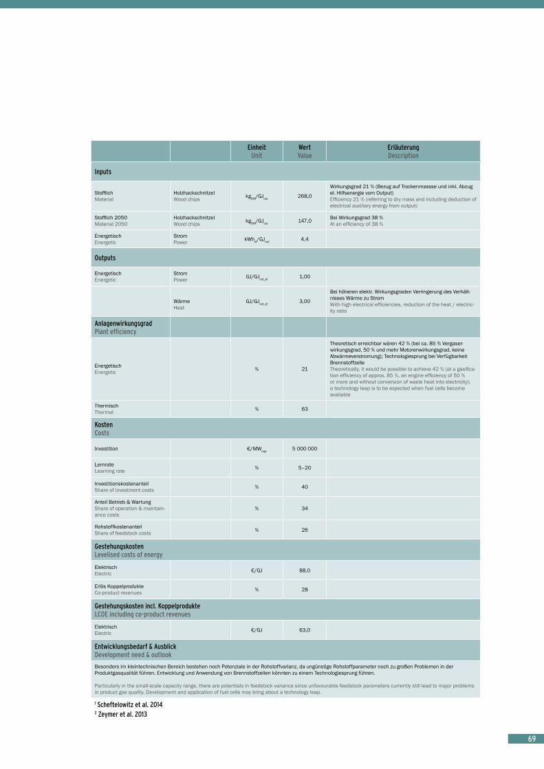
6969696969
EinheitUnit
Wert Value
Erläuterung Description
Inputs
StofflichMaterial
HolzhackschnitzelWood chips kgDM/GJout 268,0
Wirkungsgrad 21 % (Bezug auf Trockenmassse und inkl. Abzug el. Hilfsenergie vom Output) Efficiency 21 % (referring to dry mass and including deduction of electrical auxiliary energy from output)
Stofflich 2050Material 2050
HolzhackschnitzelWood chips kgDM/GJout 147,0 Bei Wirkungsgrad 38 %
At an efficiency of 38 %
EnergetischEnergetic
StromPower kWhel/GJout 4,4
Outputs
EnergetischEnergetic
StromPower GJ/GJout_el 1,00
WärmeHeat
GJ/GJout_el 3,00
Bei höheren elektr. Wirkungsgraden Verringerung des Verhält-nisses Wärme zu Strom With high electrical efficiencies, reduction of the heat / electric-ity ratio
AnlagenwirkungsgradPlant efficiency
EnergetischEnergetic % 21
Theoretisch erreichbar wären 42 % (bei ca. 85 % Vergaser-wirkungsgrad, 50 % und mehr Motorenwirkungsgrad, keine Abwärmeverstromung); Technologiesprung bei Verfügbarkeit BrennstoffzelleTheoretically, it would be possible to achieve 42 % (at a gasifica-tion efficiency of approx. 85 %, an engine efficiency of 50 % or more and without conversion of waste heat into electricity); a technology leap is to be expected when fuel cells become available
ThermischThermal % 63
KostenCosts
Investition €/MWcap 5 000 000
LernrateLearning rate % 5–20
InvestitionskostenanteilShare of investment costs % 40
Anteil Betrieb & WartungShare of operation & maintain-ance costs
% 34
RohstoffkostenanteilShare of feedstock costs % 26
GestehungskostenLevelised costs of energy
ElektrischElectric €/GJ 88,0
Erlös KoppelprodukteCo-product revenues % 28
Gestehungskosten incl. KoppelprodukteLCOE including co-product revenues
ElektrischElectric €/GJ 63,0
Entwicklungsbedarf & AusblickDevelopment need & outlook
Besonders im kleintechnischen Bereich bestehen noch Potenziale in der Rohstoffvarianz, da ungünstige Rohstoffparameter noch zu großen Problemen in der Produktgasqualität führen. Entwicklung und Anwendung von Brennstoffzellen könnten zu einem Technologiesprung führen.
Particularly in the small-scale capacity range, there are potentials in feedstock variance since unfavourable feedstock parameters currently still lead to major problems in product gas quality. Development and application of fuel cells may bring about a technology leap.
1 Scheftelowitz et al. 20142 Zeymer et al. 2013

70 Foto: SWU Energie GmbH70707070
Vergaser im mittleren Leistungsbereich sind ebenfalls Stand der Technik und einige Anlagen installiert. Bei der thermo-chemischen Vergasung und anschließendem Einsatz des Produktgasgemisches in einem Kraft-Wärme-Kopplungsprozess werden Wirkungsgrade von bis zu 40 % erreicht. Die Vergasungstechnologie bildet eine flexible Plattform zur zukünftigen Bereitstellung von Strom und Wärme, gasförmigen Energieträgern oder auch flüssigen Kraftstoffen.
Gasifiers in the medium capacity range are also state-of-the-art and some plants have been installed. In thermochemical gasification and subsequent utilisation of the product gas mixture in a combined heat and power generation process, efficiencies of up to 40 % are achie-ved. Gasification technology offers a flexible platform for the future supply of electricity and heat, gaseous energy carriers or also liquid fuels.
Vergaser KWK mittel Gasifier CHP medium
EinheitUnit
Wert Value
Erläuterung Description
Status quo
AnlagenbestandNumber of operating facilities –
Wenige Anlagen
Few Plants
Installierte LeistungInstalled capacity GW ca. 0,021 In Deutschland und Österreich
In Germany and Austria
NettostromNet power production PJ/a 0,35
ClusterCluster overview
VerfahrenProcess & technology
Vergasungsanlage von Holzhackschnitzeln oder Pellets mit anschließender Verbrennung in einem Gasmotor oder Gasturbine im ORC-Prozess im Kondensationbetrieb Gasification plant using woodchips with subsequent gas processing and combustion in a gas engine or gas turbine using the ORC process in a condensing operation
ProzessketteProcess chain
Vergasung (z.B. Wirbelschichtvergasung), Heißproduktgasreinigung, Produktgaskühlung, Kaltproduktgaswäsche, Produktgasverbren-nung im Otto-Prozess mit Generator und WärmetauscherGasification, hot product gas purification, product gas cooling, cold product gas scrubbing, product gas combustion using the Otto process with generator and heat exchanger
LeistungsspektrumPower range 1–20 MWel
EntwicklungsstandStage of development
Etablierte Technologie Established technology
Varianz der Technologie Technology variance
Vergleichsweise eingeschränkte Flexibilisierbarkeit durch beschränkte Leistungregelbarkeit und komplexes Anfahrverhalten Flexibilisation only possible to a certain extent owing to a limited power control and complex start-up procedures
ModellparameterModel parameters
AnlagePlant
Ausstoß Production of
StromPower GJ/a 291 176
Kapazität Capacity MW 10,80
Volllaststunden Full load hours h/a 7 500 Flexibler Betrieb 5 000 h
Flexible operation 5 000 h
LaufzeitLifespan (runtime) a 20

71717171
EinheitUnit
Wert Value
Erläuterung Description
Inputs
StofflichMaterial
HolzhackschnitzelWood chips kgDM/GJout 151,0
Stofflich 2050Material 2050
HolzhackschnitzelWood chips kgDM/GJout 106,0
EnergetischEnergetic
StromPower kWhel/GJout 4,4
Outputs
EnergetischEnergetic
StromPower GJ/GJout 1,00
WärmeHeat GJ/GJout 0
Wärmeauskopplung bei anderem Betriebskonzept prinzipiell möglichIn principle, heat extraction would be possible with a different operating concept
AnlagenwirkungsgradPlant efficiency
ElektrischElectric % 37
Theoretisch erreichbar wären bis 58 % (> 85 % Vergaserwir-kungsgrad, 55 % und mehr Motorenwirkungsgrad, Abwärmever-stromung); Technologiesprung bei Verfügbarkeit Brennstoffzelle Theoretically, it would be possible to achieve up to 58 % (with > 85 % gasifier efficiency, 55 % or more engine efficiency and with conversion of waste heat into electricity); a technology leap will be possible when fuel cells become available.
ThermischThermal –
Keine Wärmeauskopplung, da Konzept mit Nachverstromung No heat extraction since this concept includes conversion of waste heat into electricity
KostenCosts
Investition €/MWcap 6 600 000
LernrateLearning rate % 5–15
InvestitionskostenanteilShare of investment costs % 45
Anteil Betrieb & WartungShare of operation & maintain-ance costs
% 35
RohstoffkostenanteilShare of feedstock costs % 20
GestehungskostenLevelised costs of energy
ElektrischElectric €/GJ 81,0
Erlös KoppelprodukteCo-product revenues % 0
Gestehungskosten incl. KoppelprodukteLCOE including co-product revenues
ElektrischElectric €/GJ 81,0
Entwicklungsbedarf & AusblickDevelopment need & outlook
Potenziale in der Rohstoffvarianz; Optimierung (Forschung und Entwicklung) im Bereich Wärmerückführung, Aufbereitungsverluste und Gasreinigung notwendig
Potentials for feedstock variance; optimisation (research and development) required in the fields of re-use of heated air, processing losses and gas purification
1 Zeymer et al. 2013

72727272
Vergaser im mittleren Leistungsbereich sind Stand der Technik und die gesamte Prozesskette bis hin zu synthe-tisch hergestelltem Methan (SNG) in einigen Anlagen marktnah erprobt. Die Vergasungstechnologie bildet eine flexible Plattform zur zukünftigen Bereitstellung von Strom und Wärme, gasförmigen Energieträgern oder auch flüssigen Kraftstoffen.
Gasifiers in the medium capacity range are state-of-the-art and the entire process chain up to the production of synthetic methane (SNG) has been tested in some plants in a market-oriented way. Gasification technology provides a flexible platform for the future provision of electricity and heat, gaseous energy carriers and also liquid fuels.
Vergaser mit SNG Einspeisung Gasifier with SNG feed-in
EinheitUnit
Wert Value
Erläuterung Description
Status quo
AnlagenbestandNumber of operating facilities – 0
Keine Anlage in Deutschland; Demonstrationsanlage in Güssing (AT) und weitere in Niederlanden, Schweiz und Schweden No plants in Germany; demonstration plant in Güssing (Austria) and others in the Netherlands, Switzerland and Sweden
ClusterCluster overview
VerfahrenProcess & technology
Vergasungsanlage von Holzhackschnitzeln oder Pelletsmit anschließender Gasaufbereitung und katalytischer Synthese (z.B. CO-Methanisierung) zu SNGGasification plant using woodchips or pellets with subsequent gas processing and catalytic synthesis (e.g. CO methanisation) to produce SNG
ProzessketteProcess chain
Wirbelschichtvergasung, Produktgaskühlung mit Wärmetauscher, Kaltproduktgaswäsche, CO-Methanisiserung mit Shiftreaktion, Veredelung Fluidised bed gasification, product gas cooling with heat exchanger, cold product gas scrubbing, CO methanisation with shift reac-tion, refining
LeistungsspektrumPower range 1–100 MWSNG
EntwicklungsstandStage of development
An der Schwelle zur Marktreife und kommerziellem BetriebOn the threshold of marketability and commercial operations
Varianz der Technologie Technology variance
Relativ hohe Anforderungen an den Rohstoff, nur begrenzt flexibilisierbar durch beschränkte Leistungregelbarkeit und komplexes AnfahrverhaltenRelatively high standards required of the feedstocks, flexibilisation only possible to a certain extent owing to a limited power control and complex start-up procedures
ModellparameterModel parameters
AnlagePlant
Ausstoß Production of SNG GJ/a 730 155
Kapazität Capacity MWSNG 25,00
Volllaststunden Full load hours h/a 8 000
LaufzeitLifespan (runtime) a 25

737373
EinheitUnit
Wert Value
Erläuterung Description
Inputs
StofflichMaterial
HolzhackschnitzelWood chips kgDM/GJout 96,0
Stofflich 2050Material 2050
HolzhackschnitzelWood chips kgDM/GJout 76,5
EnergetischEnergetic
StromPower kWhel/GJout 31,0
Outputs
EnergetischEnergetic
WärmeHeat GJ/GJout 1,00
StromPower GJ/GJout 0,17
AnlagenwirkungsgradPlant efficiency
KraftstoffFuel % 58–73
Bei sehr hohen Vergasungswirkungsgrad (90 %) und Ausschöp-fung des chemischen Wirkungsgrades der Methanisierung wäre ein Konversionsgrad Biomasse zu Methan von 73 % bis zu maxi-mal 80 % (abzüglich Verluste aus der Gasreinigung) denkbar.With very high gasification efficiency (90 %) and full exploitation of the chemical efficiency of methanisation, a biomass-to-methane conversion rate of 73 % up to 80 % (minus losses due to gas purification) is conceivable.
KostenCosts
Investition €/MWcap 3 500 000Bei marktreifen AnlagenIn the case of plants ready for marketing
LernrateLearning rate % 8–10
InvestitionskostenanteilShare of investment costs % 35
Anteil Betrieb & WartungShare of operation & maintain-ance costs
% 40
RohstoffkostenanteilShare of feedstock costs % 25
GestehungskostenLevelised costs of energy
KraftstoffFuel €/GJ 35,5
Erlös KoppelprodukteCo-product revenues % 4
Gestehungskosten incl. KoppelprodukteLCOE including co-product revenues
KraftstoffFuel €/GJ 34,0
Entwicklungsbedarf & AusblickDevelopment need & outlook
Potenziale in der Rohstoffvarianz; Optimierung (Forschung und Entwicklung) im Bereich Wärmerückführung, Aufbereitungsverluste, Gasreinigung notwendig; Integration in bestehende Standorte (Industrieanlagen, Raffinerie) können zu Kostensenkungen führen.
Potentials in feedstock variance; optimisation (research and development) required in the fields of reuse of heat recovery, processing losses and gas purification; integration into existing facilities (industrial plants, refineries) may lead to reduced costs.

74
Ein Vorteil synthetischer, flüssiger Kraftstoffe über zum Beispiel den Weg der Fischer-Tropsch-Synthese (Biomass-to-Liquid-Prozess [BTL]) ist deren einfache Integration in bestehende Infrastrukturen im Mobilitätsbereich. Bei der Herstellung dieser Biokraftstoffe können verschiedene, meist lignozellulosehaltige Rohstoffe (z. B. Holz, Stroh) eingesetzt werden. Die Erzeugung von Kraftstoffen mittels FT-Prozess ist auf Basis fossiler Energieträger (Kohle, Erdgas) im kommerziellen Einsatz. Für biomassebasierte Anlagen stellen neben der Wirtschaftlichkeit jedoch unter anderem die Biomassevorbehandlung und die Vergasung technische Herausforderungen dar. Die Lignozellulose wird über verschiedene Prozesschritte in eine Vielzahl an variierbaren und damit in gewissen Grenzen an die Nach-frage orientierbaren Produktfraktionen umgewandelt. Besondere Vorteile bietet diese Technologie, da Rohstoffe mit verhältnismäßig geringen Konkurrenzen eingesetzt werden können. Ein Teil der Produkte (FT-Kerosin) kann perspektivisch auch als Flugkraftstoff eine Anwendung finden, da andere erneuerbare Alternativen hier in den nächsten Jahrzehnten nicht in Sicht sind.
An advantage of synthetic liquid fuels via, for example, Fischer-Tropsch synthesis (Biomass-to-Liquid process [BTL]) is that it can easily be integrated into existing infra-structures in the transport sector. Various feedstocks, mostly containing lignocellulose (e.g. water, straw) can be used in the production of these biofuels. The manufac-ture of fuels using FT synthesis on the basis of fossil ener-gy carriers (coal, natural gas) is in commercial use. The technical challenges facing biomass-based plants are not only commercial viability but also, among other things, the pretreatment of the biomass and gasification. The lignocellulose is converted by means of various process steps into a large number of variable product fractions which can to a certain extent be adapted to demand. This technology provides special advantages since feedstocks with relatively low levels of competition can be used. It is to be expected that in future a proportion of the products (FT kerosene) will be usable as aviation fuel since no other renewable alternatives are in sight over the next few decades.
BTL > 100 MW BTL > 100 MW
EinheitUnit
Wert Value
Erläuterung Description
Status quo
AnlagenbestandNumber of operating facilities – 0
Wenige Pilotanlagen zur Produktion flüssiger Kraftstoffe (z. B. bioliq®-Konzept des KIT Karlsruhe); bisher keine industrienahe DemoanlageA few pilot plants for the production of liquid fuels (e.g. bioliq® concept of KIT Karlsruhe); So far no near-industrial demo plant
ClusterCluster overview
VerfahrenProcess & technology
Fischer-Tropsch-Synthese von Synthesegas aus Holzvergasung zu mehreren Fraktionen, hauptsächlich FT-Diesel und FT-Kerosin (zumeist im Verhältnis 1:2); FT-Synthese über eine Methanolroute ist möglich Fischer-Tropsch synthesis of product gas from wood gasification into several fractions, mainly FT diesel and FT kerosene (mostly at a ratio of 1:2); FT-synthesis via methanol is also possible
ProzessketteProcess chain
Holzvergasung, Heißgasscheidung, Produktgaskühlung, Kaltproduktgaswäsche, CO-Methanisiserung mit Shiftreaktion, FT-Synthese und FraktionierungWood gasification, hot gas separation, product gas cooling, cold product gas cleaning, CO methanisation with shift reaction, FT synthesis and fractionation
LeistungsspektrumPower range
Bis 200 MWBtL; aufgrund Komplexität und Skalierungseffekten sind von technischer Seite eher große Anlagenkonzepte (> 100 MW) zu bevorzugen, was logistische Herausforderungen aufgrund des dezentralen Anfalls biogener Ressourcen mit sich bringtUp to 200 MWBtL; owing to complexity and scaling effects, large plant concepts (> 100 MW) are preferable from a technical point of view, entailing logistic challenges owing to the decentralised availability of biogenic resources
EntwicklungsstandStage of development
Demonstrations- und Pilotanlagen, wirtschaftlich noch nicht darstellbarDemonstration and pilot plants, not yet economically viable
Varianz der Technologie Technology variance
Relativ hohe Anforderungen an den RohstoffRelatively high feedstock requirements
ModellparameterModel parameters
AnlagePlant
Ausstoß Production of
FT-Diesel, FT-KerosinFT-Diesel, FT-Kerosene GJ/a 5 490 000 Weitere Nebenprodukte: FT-LPG, FT-Naphta
Additional by-products: FT-LPG, FT naphtha
Kapazität Capacity MWout 177
Entspricht etwa 500 MWth; Holzeinsatz von ca. 1,4 Mio t (Wassergehalt 40 %)Corresponds to approx. 500 MWth; wood input of approx. 1,4 million t (water content 40 %)
Volllaststunden Full load hours h/a 8 300
LaufzeitLifespan (runtime) a 25

75
EinheitUnit
Wert Value
Erläuterung Description
Inputs
StofflichMaterial
HolzhackschnitzelWood chips kgDM/GJout 157,0 Ca. 35 % Wirkungsgrad (Hauptprodukt FT-Diesel / -Kerosin)
Approx. 35 % efficiency (main product FT diesel/kerosene)
Stofflich 2050Material 2050
HolzhackschnitzelWood chips kgDM/GJout 126,0
EnergetischEnergetic
StromPower kWhel/GJout 69,1
Outputs
EnergetischEnergetic
BTL (FT-Diesel + FT-Kerosin(FT-diesel + FT-kerosene)
GJout 1,00 FT-Diesel/ Kerosin (Verhältnis 1:2) FT diesel/kerosene (ratio 1:2)
FT-LPG GJ/GJout 0,08
FT-Naphtha GJ/GJout 0,38 Ca. 8,4 kg/GJ Approx. 8,4 kg/GJ
AnlagenwirkungsgradPlant efficiency
KraftstoffFuel % 35–45
35 % Wirkungsgrad konservativer Ansatz (bei Hauptprodukt FT-Diesel); Wirkungsgrade extrem abhängig von den getroffenen Annahmen, z.B. Ausschöpfung der Möglichkeiten der Wärme-rückführung, Prozessintegration und Katalysatorentwicklung; der Fischer-Tropsch-Prozess liefert zudem ein breites Zwischen-produktgemisch (Methan, Ethan, Propan, Butan, Naphta, Kerosin, Diesel, Wachse), wovon nur ein Teil nutzbar ist Conservative approach (with main product FT diesel); efficiency is extremely dependent on the assumptions made, e.g. exhaus-tion of potentials for heat recirculation, process integration and catalytic converter development; the Fischer-Tropsch process also results in a broad mixture of intermediate products (methane, ethane, propane, butane, naphtha, kerosene, diesel, waxes), only some of which are usable
KostenCosts
Investition €/MWcap 3 850 000
Bei marktreifen Anlagen (eventuell auch deutlich teuerer > 4 000 €/kWout); entspricht für diese Anlage etwa 680 Mio. €; große Spannbreite an in der Literatur angenommenen Investiti-onsaufwendungen In the case of plants ready for the market (possibly also much more expensive > 4 000 €/kWout); for this plant, this corre-sponds to approx. € 680 million; wide range of assumed figures for investment expenditure in the literature
LernrateLearning rate % 8–10
InvestitionskostenanteilShare of investment costs % 32
Anteil Betrieb & WartungShare of operation & maintain-ance costs
% 40
RohstoffkostenanteilShare of feedstock costs % 28
GestehungskostenLevelised costs of energy
KraftstoffFuel €/GJ 47,7
Erlös KoppelprodukteCo-product revenues % 0,07
FT-LPG; FT-Naphta in der Regel wertlosFT-LPG; FT naphtha usually of no value
Gestehungskosten incl. KoppelprodukteLCOE including co-product revenues
KraftstoffFuel €/GJ 47,6
Entwicklungsbedarf & AusblickDevelopment need & outlook
Ausbeutesteigerung des FT-Prozesses (z. B. Katalysatorforschung), Abstimmung der einzelnen Prozessschritte (Wärmerückführung), Diversifizierung des Biomassein-puts
Improvement of yield from the FT process (e.g. through research on catalytic converters) , coordination of individual process steps (heat recirculation), diversification of biomass input

7676
© DBFZ
EntwicklungstrendsHerausforderungen an die technische Weiterentwicklung
Developmental trendsChallenges for further technical advancement

77
Anaerobe Vergärung
Biogasanlagen haben in Deutschland einen starken Zubau erfahren. Die Verfahrensschritte zur Bereit-stellung von Biogas aus vorrangig nachwachsenden Rohstoffen (Energiepflanzen, aber auch Reststoffen und Abfällen) und dessen Umwandlung zu Strom und Wärme oder Aufbereitung zu Kraftstoff sind etabliert. Die Biogastechnologie hat sich in den letzten Jahren infolge der dynamischen Entwicklung an viele sich ändernde Randbedingungen angepasst. Als Beispiel seien hier die steigenden Kosten, veränderte Genehmigungsbedingun-gen oder aktuell die Flexibilisierung der Energiebereitstel-lung genannt. Aufgrund der stark rückläufigen Zahlen in Deutschland im Zubau von Neuanlagen orientieren sich deutsche Unternehmen, die in Anlagenplanung und -bau tätig sind, aktuell auf die internationalen Märkte. Vor dem Hintergrund der geänderten gesetzlichen Rahmenbedin-gungen (EEG 2012 und 2014) wird der Leistungszubau im Biogasbereich überwiegend von Anlagenerweiterun-gen, Umstellungen auf den flexiblen Anlagenbetrieb sowie Güllekleinanlagen und Anlagen im Abfallbereich bestimmt sein.
Allgemein ist im Biogasbereich und in der Biogasaufbe-reitung zukünftig mit einer weiteren Effizienzsteigerung (u. a. Substratvorbehandlung, mikrobiologischer Prozess, hohe elektrische Wirkungsgrade durch Brennstoffzelle, hohe Wärmenutzung) zu rechnen. Die Weiterentwicklung bezieht sich dabei nicht nur auf die Anlagentechnik selbst sondern umfasst die gesamte Kette vom Substratanfall bzw. der Substratbereitstellung bis hin zur Nutzung des Biogases. Dabei steht nicht nur die Erhöhung der spezifischen Biogasausbeute im Fokus, häufig ist es eher die Verfügbarkeit der Anlagen (Verringerung von Ausfallzeiten) und die Verminderung von Verlusten in der gesamten Kette. Für die Zukunft ist zu erwarten, dass mit einem größeren Anteil der Erneuerbaren Energien in den Energienetzen auch der Anteil an flexibler, dem Bedarf angepasster Energiebereitstellung steigen wird. Damit verbunden ist die Entwicklung von Komponenten gezielt für bedarfsgerechte Bereitstellung (z. B. Stand-festigkeit von Motoren bei Lastwechsel, leistungsfähiger Zustandserkennung, Prozessregelung und Fernüberwa-chung). Das bedingt eine Entwicklung besserer Sensoren und Regelungssysteme zur Prozessüberwachung.
Anaerobic digestion
Biogas plants have undergone great expansion in Germa-ny. The processing steps for producing biogas from mainly renewable feedstocks (energy crops as well as residual and waste materials) and for converting it into electricity and heat, or for processing it into fuel, are already well established. Over the past few years, the dynamic deve-lopment of biogas technology has enabled it to adapt to changing framework conditions, for example the growing costs, changed licensing conditions and, currently, the flexibilisation of energy production. Owing to the sharply declining figures in Germany for the construction of new plants, German companies involved in planning and cons-tructing such plants are currently focusing more on inter-national markets. Against the background of the changed legal provisions (the Renewable Energy Acts, EEG, of 2012 and 2014), the increased capacity in the sphere of biogas plants is mainly expected to take the form of plant expansions, conversion to flexible plant operations and the construction of small-scale liquid manure and waste processing plants.
It is to be expected that there will be further improve-ments in efficiency in the biogas sector in general and in the processing of biogas (such as; substrate pre-treatment, microbiological process, electrical efficiencies through fuel cells and thermal utilisation). Development will take place not only as regards the systems technology itself; it will also affect the entire chain, from substrate procurement and substrate preparation, to the utilisa-tion of the biogas. The focus of this development is not only on increasing the specific biogas yield; often it is on the availability of plants (reducing downtimes) and the reduction of losses throughout the entire chain. For the future, it is to be expected that with a larger proportion of renewables in the energy supply networks, the proportion of flexible, demand-driven energy supplies will increase. Associated with this is also the development of compo-nents specifically for demand-driven energy provision (e.g. stability of motors with changing loads, efficient state detection, process regulation and remote monitoring). This requires the development of improved sensors and control systems for process monitoring.

7878
Der Hauptanteil der Substrate für die anaerobe Vergärung wird auch im Jahr 2020 durch organische Abfälle, land-wirtschaftliche Reststoffe und Energiepflanzen geprägt sein. Der Einsatz von Energiepflanzen zur Stromerzeu-gung in Biogasanlagen (EEG) wird schrittweise bis 2030 auslaufen, da mit Anpassung den Vergütungssätzen (EEG 2012, EEG 2014) keine Anreize mehr für den Einsatz von Energiepflanzen besteht. Biomasse (Energiepflan-zen) wird bis 2050 zunehmend stofflich genutzt werden, da die Stromproduktion (u .a. hoher Betriebskosten / Rohstoffkostenanteil; Konkurrenz zu Wind und Photo-voltaik) von abnehmender Bedeutung sein wird. In der Übergangszeit kann durch Biogas über die weitergehende Flexibilisierung der Biogasanlagen ein bedarfsgerechter Betrieb realisiert werden und einen hohen Stellenwert erreichen zum Beispiel zur Stromnetzstabilisierung zum Ausgleich von fluktuierender Strombereitstellung (Wind, Photovoltaik).
Ein weiterer, aktueller Trend ist die Vor-Ort-Verstromung von Biogas aus güllebasierte Kleinanlagen. Diese bieten durch Kostensenkungseffekte (einfache Fertigbauan-lagen, direkte Integration in Stallneubau) und konkur-renzfreie Stoffströme ein Ausbaupotenzial. Aufgrund der Vorteile der dezentralen Energiebereitstellung auf Basis landwirtschaftlicher Reststoffe wird die Güllenutzung zur Energieerzeugung auch perspektivisch eine Option sein. Bei großen Anlagen (möglicherweise auch Repowering mittlerer Anlagen bei Standorten mit hoher Wertschöp-fung aus der Wärmenutzung) wird der Fokus auf der Biogasaufbereitung und Einspeisung von Biomethan mit der Möglichkeit der flexiblen Nutzung für die Bereitstel-lung von Strom, Wärme und vor allem Kraftstoff sein. Die Trockenfermentation wird jedoch weiter als Nischenan-wendung (Landschaftspflegematerial, organische Abfälle – hier ggfs. Zunahme durch verpflichtende Einführung der Biotonne gegenüber Kompostierung) eine Rolle spielen. Prinzipiell können Biogasanlagen vorrangig der Behand-lung von Abfällen oder der Energiebereitstellung dienen. Je nach Konzept stellen sich unterschiedliche Kosten-strukturen dar. Generell ist jedoch zu verzeichnen, dass die Energieerzeugung bei großen Anlagen wirtschaft-lich zu realisieren ist, während sich eine nachhaltige Reststoffbehandlung (z. B. Gülle, Abfälle) besonders mit kleinen, dezentralen Konzepten umsetzen lässt.
Das Potenzial für die Einbindung von Biogasanlagen in Kaskaden (Bioraffinerien, Schlempevergärung) ist hoch. Generell wird sich die Entwicklung in Richtung einer kostengünstigeren und energieeffizienteren Konversi-onstechnologie verstärken. Mit der bedarfsgerechten Energiebereitstellung werden auch erweiterte Konzepte, wie z. B. Power to Gas, Speicherung von Energieträ-gern etc. verstärkte Anwendung finden. Die Integration von dezentralen Anlagen in ein sich stark änderndes Energiekonzept wird ein zentrales Forschungsgebiet der nächsten Jahre sein.
In 2020 the bulk of substrates for anaerobic digestion will still be made up of organic waste, agricultural residues and energy crops. The use of energy crops for electricity generation in biogas plants (EEG) will gradually be phased out by 2030 since the reduction of feed-in tariffs (under EEG 2012, EEG 2014) will remove the incentive for the use of energy crops. By 2050, biomass (energy crops) will increasingly be put to material use, since electricity production will be of decreasing significance (owing, among other things, to high operating costs / feedstock costs; competition with wind and photovoltaic power). During the transition period, sufficient power supplies can be provided using biogas through the continued flexibili-sation of biogas plants and can play an important role, for example in stabilising electricity networks by compensa-ting for fluctuating energy supplies (wind, photovoltaic systems).
Another current trend is the local use of biogas electricity generation derived from liquid manure-based small-scale power plants. These offer potential for expansion owing to their cost reducing effects (simple prefabricated plants, direct integration into new buildings) and non-competitive substance flows. Owing to the advantages offered by decentralised energy production on the basis of agri-cultural residues, the use of liquid manure for energy production is also an option with good prospects for the future. With large plants (possibly also the repowering of medium-sized plants in locations with high added value through thermal utilisation), the focus will be on biogas processing and the feed-in of biomethane into the energy supply with the possibility of the flexible utilisation of electricity, heat and especially fuels. However, dry fermen-tation will continue to play a role as a niche application (material from landscaping activities, organic waste – possibly with the compulsory introduction of organic waste bins instead of composting). In principle, biogas plants can be primarily used either for the treatment of waste or for producing energy. There are different cost structures depending on each concept. Generally, howe-ver, it is evident that energy can be produced economic-ally in large plants, whereas the sustainable processing of residual materials (e.g. liquid manure, waste) can be performed particularly well using small, decentralised concepts.
The potential for integrating biogas plants into cascades (biorefineries, slurry digestion) is high. In general, there is likely to be a stronger development towards low-cost and energy efficient conversion technologies. With demand-driven energy production, further concepts such as power-to-gas, storage of energy sources etc. will be implemented more broadly. The integration of decentralised plants into a rapidly changing energy concept will be a key area for research over the coming years.

7979
Alkoholische Fermentation
Die Ethanolproduktion aus zucker- und stärkehaltigen Rohstoffen ist in Deutschland etabliert. Die eingesetzten Rohstoffe sind derzeit Getreide und Zuckerrüben aus der landwirtschaftlichen Produktion. Neben dem Hauptpro-dukt Ethanol leisten Nebenprodukte, wie z. B. Futtermit-tel, Biogas, Düngemittel und evtl. Lebensmittelzusätze, einen wichtigen Beitrag zur Wirtschaftlichkeit dieser Anlagen. Die Effizienz der einzelnen Verarbeitungsschritte ist hoch, sodass kurzfristig nur kleine Optimierungen der Verfahrenstechnik zu erwarten sind. Eine Installation neuer zucker- oder stärkebasierter Anlagen in Deutsch-land ist abhängig von zusätzlichen politischen Anreizen. Große Fortschritte konnten bei der Entwicklung von Tech-nologien zur Ethanolproduktion aus lignozellulosehaltigen Rohstoffen (z. B. Stroh, Holz) erreicht werden. Mittel- bis langfristig ist daher eine verstärkte Nutzung von land- und forstwirtschaftlichen Reststoffen zur Ethanolproduktion wahrscheinlich. Eine Kommerzialisierung dieser Technolo-gien beginnt derzeit mit dem Bau der ersten Produktions-anlagen, jedoch bislang nicht in Deutschland.
Weltweit wird ein Zubau der Fermentationsanlagenkapazi-tät, insbesondere der Bioethanolproduktion aus Zellulose und Zuckerrohr, erwartet.Zudem kann Ethanol zukünftig ein wichtiger Baustein für die stoffliche Nutzung in einer biobasierten Chemie werden.
Alcoholic fermentation
Ethanol production from sugar and starch-based feedstocks is well-established in Germany. The main feedstocks for ethanol production are grains and sugar beet and are currently obtained primarily from agricul-tural production. Beside ethanol as the primary product a range of by-products such as animal feed, biogas, fertilizers and possibly food additives contribute to the economics of the ethanol plants. The efficiencies of the conversion processing steps are already high. In the short term only minor optimisations are therefore expected. The installation of new, particularly sugar or starch-based ethanol plants in Germany will depend on further development of political incentives. On the other hand major achievements are made in the development of technologies to convert lignocellulosic feedstocks (e.g. straw, wood) into ethanol. Over the medium to long term, ethanol production from agricultural and forest residues is likely to be realised. The commercialisation of these tech-nologies is promoted by installation of the first production plants, however, not yet in Germany.
It is expected that there will be an increase in the capacity of fermentation plants all over the world, particularly for bioethanol production based on cellulose and sugarcane. In the future ethanol can be an important component for industrial utilisation within a bio-based chemical industry.
Foto: Gerald Schilling,Südzucker AG, Zeitz

8080
Ver- / Umesterung, Hydroprocessing
Die Technologien zur Veresterung bzw. der Hydroprozes-sierung von Pflanzenölen, in der Regel Rapsöl, Palmöl und (Altspeise-) Fetten, sind etabliert. Die Verfahrens-schritte von der Rapssaat zum Kraftstoff liefern wichtige Nebenprodukte wie eiweißreiche Futtermittel und Glycerin. Das Potenzial für technische Optimierungen der eigentlichen Konversionsschritte ist insgesamt eher gering. In Europa ist absehbar, dass es mit Verweis auf die Limitierung von Kraftstoffen aus Rohstoffen, die auch im Nahrungsmittelsektor eingesetzt werden können (gemäß der in 2015 überarbeiteten EU RED) und die Limi-tierungen in der Beimischung zu Mineralölkraftstoffen nur ein geringer Zubau an Anlagen zur Ver- / Umesterung ab 2020 erwartet wird. Rohstoffseitige Veränderungen (Verwertung von Altspeisefetten / -ölen) sind zu erwarten. HVO und HEFA (hydroprozessierte Öle und Fette) haben den Vorteil, entsprechend adaptiert auf Kerosin auch als Flugkraftstoff eingesetzt werden zu können. In Deutschland eingesetztes HVO wird derzeit ausschließ-lich importiert. Die direkte Nutzung von Pflanzenölen im Verkehrssektor ist als eine Nischenanwendung (z. B. landwirtschaftliche Anwendungen) zu betrachten.
Esterification / trans- esterification, hydroprocessing
The technologies for esterification and hydroprocessing of vegetable oils, usually rapeseed oil, palm oil and used cooking fats are well-established. The various stages in the process of transforming rapeseed into fuel result in important by-products such as protein-rich animal feed and glycerol. The potential for technical optimisation of the actual conversion steps is rather limited. In Europe it is foreseeable that there will be only a limited number of new (trans-) esterification plants after 2020 due to the limitation of biofuels admixture from food and feed crops (according the EU RED 2015. Changes in feedstocks (recycling of used cooking fats and oil) are anticipated. HVO (hydrogenated vegetable oil) and HEFA (hydro-processed esters and fatty acids) have the advantage that they can, adapted to kerosene, be used as jet fuel. HVO used in Germany is currently all imported. The direct use of vegetable oils in the transport sector can be regarded only as a niche application (e.g. in agriculture).
Foto: Sebastian Spindler_pixelio.de

8181
Verbrennung
Im Bereich der direkten Verbrennung von Biomasse, in der Regel Holz unterschiedlicher Kategorien, gibt es eine große Bandbreite an Technologien und Anlagengrößen. Für die reine Wärmebereitstellung werden in Deutschland derzeit ca. 12 bis 14 Millionen Einzelraumfeuerstätten und ca. 1 Millionen Zentralheizungsanlagen betrieben. Moderne Systeme im kleinen Leistungsbereich (Pelletkes-sel; Mikro-KWK) gewinnen erst seit kurzem an Bedeu-tung. Im mittleren bis hohen Leistungsbereich (bis ca. 20 MWel.) stellen holzbasierte Heizwerke und Heizkraft-werke in unterschiedlichem Umfang Wärme (Industrie, kommunale Wärmenetze) und Strom (zumeist in KWK) bereit.
Eine ökonomisch / ökologisch basierte Prognose gestaltet sich bei den Einzelraumfeuerstätten schwierig. Im Privat-bereich wird Biomasse aufgrund der hohen Affinität der Menschen in Deutschland zum eigenen Feuer eine hohe Bedeutung behalten. Zukünftig werden Einzelraumfeuer-stätten zunehmend mit integrierten Warmwassertaschen und Einbindung in ein zentrales Heizungssystem angebo-ten und eingesetzt werden. In Verbindung mit automati-schen Zündeinrichtungen und moderner Kommunikati-onstechnik werden auch diese zur bedarfsgerechten und flexiblen Wärmebereitstellung beitragen. Dabei wird ein stromloser Notbetrieb vielfach die Prämisse bleiben, um den Kunden ein Gefühl von Sicherheit zu verleihen.
Zentralheizungsanlagen (Pellet- und Holzhackschnitzel-kessel) werden ab 2030 verstärkt zu bedarfsgerechten Schließen von Wärmeversorgungslücken eingesetzt werden. D. h., sie werden nur dann betrieben, wenn Solarthermie, Abwärme, Wärme aus Überschussstrom und geothermische Wärme nicht oder nur unter zu hohen Kosten verfügbar ist.
Combustion
Within the conversion system of the direct combustion of biomass, usually wood of different categories, there is a wide range of technologies and plant sizes. For heat-only generation, approx. 12 to 14 million single room combustion units and approx. 1 million central heating systems are currently in operation in Germany. Modern systems in the small-scale capacity range (pellet boilers; micro-CHP systems) have only recently started to gain in significance. In the medium to large-scale capacity range (up to approx. 20 MWel.), Wood-based heating plants and cogeneration plants produce different amounts of heat (industry, district heating networks) and electricity (mostly in CHP units).
It is difficult to make a prognosis concerning single room combustion units on the basis of economic or environ-mental considerations. In private households, biomass will continue to play a very significant role due to the popularity among Germans of having their own fire. In future, single room combustion units will increasingly be sold and used with integrated hot water storage tanks and be connected to a central heating system. In combination with automatic ignition devices and modern communications technology, they will also contribute to demand-driven and flexible heat generation. Currentless emergency operation will remain important for providing customers with a feeling of security.
From 2030 onwards, central heating systems (pellet and woodchip boilers in the domestic and residential markets) will increasingly be used to bridge gaps in the heat supply as necessary, i.e. they only come into operation when solar thermics, waste heat, heat generated from surplus electricity and geothermal heat are not available or are excessively expensive.

8282
Bis 2020 werden Technologien zur Emissionsminderung (u. a. Feinstaub, NOx) eine zunehmende Rolle spielen. Weitergehende Effizienzsteigerungen werden erreicht, vermutlich hauptsächlich durch Optimierungen der Verbrennungstechnologie und Systemautomation. Die Anzahl größerer Heizkraftwerke (Industrie, Fernwärme) dürfte nicht signifikant steigen. Bis 2020 wird erwartet, dass Anlagen im Bereich von 10 MW vom Netz gehen werden. Die meisten Technologien werden perspektivisch eher zu thermo-chemischen Vergasungstechnologien weiterentwickelt. Eine mögliche Entwicklung (Haupttrei-ber: CO2-Zertifikate-Preis) ist die Mitverbrennung von holzartigen Biomassen, welche jedoch nur übergangswei-se relevant werden könnte.
Bedarfsorientierte, dezentrale Systeme (Klein-KWK) können als kurzfristig und Mikro-KWK-Systeme als mittelfristig marktverfügbar angenommen werden und entlasten, eine ökonomische Darstellbarkeit vorausge-setzt, das Stromnetz.
Mit Blick auf den Zeithorizont 2050 gibt es weitere Prog-noseunsicherheiten unter anderem beim Wärmebedarf (z. B. Grad der Gebäudesanierung) und der Entwicklung innovativer Speicherkonzepte für die Stabilisierung des Stromsystems und damit dem Grad der Flexibilisierung von Festbrennstoff-KWK. Festbrennstoffe stehen zudem in starker Konkurrenz zur stofflichen Nutzung, die zum Beispiel im Rahmen des Ausbaus von Bioraffinerien im Rahmen einer Bioökonomie zunehmen könnte. Abgesehen von der Nutzung von Festbrennstoffen steht die Verbrennung von Pflanzenölen, insbesondere Rapsöl und Palmöl, zur gekoppelten Strom- und Wärmebereit-stellung als Technologie zur Verfügung. Insbesondere der hohe Rohstoffkostenanteil an den Strom- / Wärmegeste-hungskosten stellt bei stark volatilen Rohstoffkosten ein hohes Risiko für den Betrieb von mit Pflanzenöl betrie-benen BHKW dar. Ähnlich dem Einsatz als Reinkraftstoff sind perspektivisch Pflanzenöl-BHKW als Nischenanwen-dung zu sehen.
Up to 2020, technologies for reducing emissions (e.g. particulates, NOx) will play an increasing role. There will be further improvements in efficiency, presumably mainly through the optimisation of combustion technologies and system automation. The number of large-scale coge-neration plants (industrial markets, district heating) is unlikely to rise significantly. Up to 2020 it is anticipated that plants in the 10 MW range will be decommissioned. In the long term, most technologies will probably be deve-loped further into thermochemical gasification technolo-gies. A possible development (the main incentive being CO2 emissions certificate prices) is the co-combustion of woody biomass, which may, however, only be relevant for a transitional period.
It can be assumed that in the short term demand-driven, decentralised systems (small-scale CHP units), and in the medium term micro-CHP systems, will become available on the market and will reduce the load on the electricity grid, provided they are economically viable.
Looking ahead to the year 2050, there are further uncer-tainty factors affecting the prognosis, including demand for heating (e.g. depending on the degree of building modernisation) and the development of innovative storage concepts for the stabilisation of the electricity system and thus the degree of flexibilisation of solid-fuel CHP units. Furthermore, solid fuels are in strong compe-tition with material utilisation, which could increase, for example in connection with the expansion of biorefineries as part of the bioeconomy strategy.
Apart from the use of solid fuels, the combustion of vege-table oils, particularly rapeseed and palm oil, is available as a technology for combined electricity and heat genera-tion. In particular, the high proportion of feedstock costs in the levelised cost of energy constitutes a high risk for the operation of CHP plants due to the highly volatile nature of the feedstock costs. Like the use of vegetable oil purely as a fuel, the operation of vegetable oil-based CHP systems is likely to remain a niche application and not widely implemented.
Foto: kennz_pixelio.de

8383
Biomass gasification
In the area of thermochemical gasification, there is a wide range of technologies both for electricity and heat generation and for the supply of a wide range of gaseous (Bio-SNG) (cf. Rönsch & Ortwein 2011) and liquid (FT diesel, FT kerosene) fuels.
Small gasifiers are capable of being regulated good and fast during their operation. With increasing plant sizes and its complexity and heat-up demand, larger gasifica-tion plants for electricity generation are to be regarded as relatively inflexible owing to the requirements of the electricity system and with respect to e.g. biogas or biomethane. They would be ideally suitable, depending on the technology, for further covering the base load in the future electricity system. The production of hydrogen by means of gasification is technically possible (Zech et al. 2013) but tends not (yet) to be economically viable without subsidies (see for example current developments (EEG 2014) in the German biogas sector).
From 2020 onwards, Bio-SNG (biomethane) could be produced by means of thermochemical gasification processes and syntheses and be used, for example, in the transport sector (Rönsch et al. 2009). Its implemen-tation on the market is, however, very uncertain as one can observe the current developments of the biomethane (via biogas) industry. The development of these plant concepts, with achieving necessary cost reductions, is being pursued since lignocellulose derived from residues (straw, residual forest wood) can be used as input. Its use is comparable with biomethane derived from anaerobic digestion focusing on electricity (system integration) and fuels, but in future the material utilisation of synthetic products will also be possible. The promotion of Bio-SNG would also have to include larger-scale plants, since larger plant capacities are to be expected (from approx. 20–40 MW upwards). Bio-SNG could be combined with other industrial processes (biorefineries) and consumed locally.
Plants for producing liquid fuels from lignocellulose (Fischer-Tropsch fuels, BtL) are currently only in the pilot phase. From today’s perspective, also having technical and economic risks in mind, the construction of large complex BtL plants remains uncertain. On the other hand, the utilisation of liquid fuels derived from gasification and other synthesis cycles (e.g. FT kerosene) is anticipated to become a growing technology – provided the economic conditions are favourable – particularly in special fields of application such as aviation. Large gasifiers could possibly also provide the chemical industry with synthesis gas or hydrogen.
Biomasse-Vergasung
Im Bereich der thermo-chemischen Vergasung gibt es eine breite Palette an Technologien sowohl zur Strom- und Wärmebereitstellung als auch zur Bereitstellung verschie-denster gasförmiger (Bio-SNG) (vgl. Rönsch & Ortwein 2011) und flüssiger (FT-Diesel, FT-Kerosin) Kraftstoffe. Kleine Vergasungsanlagen können sehr gut und schnell geregelt werden. Mit steigender Anlagengröße und damit Komplexität und Aufheizbedarf sind die größeren Verga-sungsanlagen zur Strombereitstellung vor dem Hinter-grund der Anforderungen des Stromsystems im Vergleich zu Biogas / Biomethan eher als weniger flexibel einzustu-fen und wären auch zukünftig je nach Technologie für die Deckung der Grundlast prädestiniert. Die Produktion von Wasserstoff über Vergasung ist technisch möglich (Zech et al. 2013), jedoch wirtschaftlich ohne Förderung (wie auch das Beispiel Biogasanlagen zeigt) nicht tragfähig.
Bio-SNG (Biomethan) könnte ab 2020 über thermoche-mische Vergasungsprozesse und Synthesen produziert und zum Beispiel auch im Verkehrssektor genutzt werden (Rönsch et al. 2009). Die Marktimplementie-rung - trotz vorhandener Infrastrukturen - ist jedoch auch vor dem Hintergrund der verhaltenen Entwicklungen der Biomethanbranche sehr ungewiss. Die Entwicklung dieser Anlagenkonzepte unter Erschließung von Kosten-senkungspotenzialen wird angestrebt, da Lignozellulose aus Reststoffen (Stroh, Waldrestholz) als Input genutzt werden kann. Die Nutzung ist vergleichbar mit Biomethan aus anaerober Vergärung mit Fokus auf Strom (Systemin-tegration) und Kraftstoffen aber auch zukünftig stofflicher Nutzung von Syntheseprodukten. Eine Förderung von Bio-SNG müsste auch größere Anlagen umfassen, da eher Anlagenkapazitäten ab ca. 20-40 MW zu erwarten sind. Bio-SNG könnte zukünftig mit anderen industri-ellen Prozessen (Bioraffinerien) gekoppelt und vor Ort verbraucht werden.
Anlagen zur Bereitstellung von flüssigen Kraftstoffen aus Lignozellulose (Fischer-Tropsch-Kraftstoffe, BtL) befinden sich derzeit noch im Pilotstatus. Die Realisierung großer, komplexer BtL-Anlagen ist aus derzeitiger Sicht auch mit Blick auf die damit verbundenen technischen und ökono-mischen Risiken unsicher. Der Einsatz von flüssigen Kraft-stoffen aus Vergasungs- und weiteren Syntheseschritten (z. B. FT-Kerosin) kann demgegenüber, günstige ökonomi-sche Bedingungen vorausgesetzt, vorrangig in speziellen Anwendungsfeldern wie dem Luftverkehr als zukünftig zunehmende Technologie erwartet werden. Große Verga-ser können zukünftig auch eine Rolle bei der Versorgung der Chemieindustrie (Synthesegas, H2) spielen.

84
Summary
In many national and international studies, bioenergy is a relevant and growing source for supplying power, heat and fuel. Today, bioenergy makes a large contribution to renewable energy provision and owing to the expectations of bioenergy – the potential to reduce greenhouse gas emissions, the balancing function in the electricity supply system, the reduction of costs, and the lack of alternati-ves or necessity for selected fields of application – it will continue to play a relevant role in the future. It is necessary to conduct targeted bioenergy research and to optimise and further develop the technologies, process steps and applications in order to achieve more flexible and efficient bioenergy supplies, in particular as regards the feedstocks and the demand side. This overview of developmental trends in various technologies and the classification of certain parameters will be able to help further studies, scenarios and model simulations to identify the role of future bioenergy and to describe its integration into energy and material systems more clearly.
For the further development of highly promising, innova-tive technology approaches – in particular for advanced biofuels13, demand-driven power supply and smart heat concepts (Thrän 2015) – a long-term political framework is the fundamental basis for the planning security of all stakeholders in economy, civil society, research and poli-cy. The expansion of biofuel production and the market implementation of innovative technology approaches are currently expected only in individual cases which is a result of the current political framework until 2020 and beyond14. Important measures for the future will be pursu-ing support systems (e.g. research agenda, roadmaps, quotas, tax exemptions) both for the further integration of bioenergy technologies in the heat and power sector and the establishment of alternative biofuels, the quantifica-tion and utilization of preferred feedstocks as well as the adaption and enhancement of accompanying control and certification systems.
Fazit
In vielen nationalen wie globalen Studien ist Bioenergie ein relevanter, in der Regel quantitativ weiter steigender Bestandteil der Wärmeversorgung sowie der Strom- und Kraftstoffbereitstellung. Bioenergie trägt heute global zu einem Großteil der erneuerbaren Energiebereitstel-lung bei und spielt zukünftig aufgrund der Erwartungen an Bioenergie - Treibhausgasminderungspotenzial, Ausgleichsfunktion im Stromsystem, Kostenreduktion, Alternativlosigkeit beziehungsweise Notwendigkeit in ausgewählten Anwendungsfeldern - eine weiterhin rele-vante Rolle. Die gezielte Bioenergieforschung und die Optimierung und Weiterentwicklung der Technologien, Prozessschritte und Anwendungen hin zu einer, insbesondere bezüglich der Rohstoffe und der Nachfrageseite, flexiblen und effizienten Bioenergiebereitstellung ist notwendig. Die Übersicht über Entwicklungstrends verschiedener Techno-logien und Einordnung bestimmter Kenngrößen können weiteren Studien, Szenarien und Modellierungen helfen, die Rolle der zukünftigen Bioenergie herauszuarbeiten und deren Integration in Energie- und Stoffsysteme noch besser abzubilden.
Für die Weiterentwicklung von vielversprechenden innova-tiven Technologieansätzen - insbesondere für fortschrittli-che Biokraftstoffe13, bedarfsgerechte Strombereitstellung und smarte Wärmebereitstellungskonzepte (Thrän 2015) – sind für die Planungssicherheit aller Akteure aus Wirt-schaft, Zivilgesellschaft, Forschung und Politik vor allem langfristig verbindliche politische Rahmenbedingungen entscheidend. Ein Ausbau der Biokraftstoffproduktion und die Marktetablierung innovativer Technologieansätze sind, bedingt durch die mangelnde Ziel- und Planungssi-cherheit, nur in Einzelfällen zu erwarten. Dies resultiert aus den politischen Rahmenbedingungen bis 2020 und darüber hinaus14. Wichtig sind daher insbesondere weiterführende Fördersysteme (z. B. Forschungsförde-rung, Roadmaps, Quoten, Marktanreizprogramme, Steu-erbefreiungen) für die Weiterentwicklung der biogenen Wärme- und Strombereitstellung und die Etablierung alternativer Kraftstoffe, die Quantifizierung und Nutzbar-machung der Potenziale präferierter Rohstoffe sowie die Anpassung und Weiterentwicklung flankierender Kontroll- und Zertifizierungssysteme.
13 Derzeit bilden die seitens der Europäischen Kommission vorgegebenen Direktiven bereits einen verbindlichen Rahmen. Hier sind maßgeblich die Erneuerbare-Energien-Richtlinie (kurz RED) 2009/28/EG und die Kraftstoffqualitätsrichtlinie (kurz FQD) 2009/30/EG zu nennen, die beide jedoch zunächst nur bis 2020 gelten. Auch ist die Infrastrukturrichtlinie 2014/94/EG relevant.
14 Für Biokraftstoffe relevant sind vor allem die vor dem Hinter-grund der seit 2012 diskutierten und am 9. September 2015 verabschiedeten Änderungen zur RED und FQD (Richtlinie [EU] 2015/1513).
13 Currently the directives given by the European Commission have formed already a binding framework. Here, the most relevant are the Renewable Energy Directive (short RED) 2009/28/EC and the “Fuel Quality Directive” (short FQD) 2009/30/EC, which, however, apply only until 2020. Further, the „Infrastructure Directive“ 2014/94/EU is relevant.
14 For liquid biofuels the amendments of the RED and FQD adopted on the 9th of September, 2015 (Directive [EU] 2015/1513), which have been discussed since 2012, are relevant.

85
Abkürzung Abbreviation
Erklärung Explanation
a Jahr(e) year(s)
AGEE-Stat Arbeitsgruppe Erneuerbare Energien - Statistik Working Group on Renewable Energies - Statistics
BAU business as usual-Szenarium mit unveränderten Rahmenbedingungen
Business as usual
BHKW Blockheizkraftwerk Combined heat and power plant (see CHP)
BImSchV Bundes-Immissionsschutzverordnung German Ordiance on Federal Immission Control
BMEL Bundesministerium für Ernährung und Landwirt-schaft
Federal Ministry of Food and Agriculture
BMWi Bundesministerium für Wirtschaft und Energie Federal Ministry of Economics and Technology
BtL Biomasseverflüssigung Biomass to liquid
C.A.R.M.E.N. Centrales Agrar-Rohstoff Marketing- und Energie-Netzwerk
Central Agrarian Raw Material Marketing and Devel-opment Network
cap Kapazität Capacity
CCS Kohlenstoffabscheidung und -speicherung Carbon capture and storage
CHP Kraft-Wärme-Kopplung (siehe KWK) Combined heat and power plant
CO / CO2 Kohlenstoffmonoxid / -dioxid Carbonmonoxid / -dioxid
DBFZ Deutsches Biomasseforschungszentrum, Leipzig German Biomass Research Centre, Leipzig
DDGS Trockenschlempe Dried distillers grains with solubles
DEPV Deutscher Energieholz- und Pellet-Verband German Association for Energy Wood and Pellets
DIN EN (ISO) Deutsche Übernahme einer europäischen Norm (unter Federführung der Internationale Organisati-on für Normung)
German adoption of an european norm (leaded by the International Organization for Standardization)
DM Trockenmasse Dry matter
DME Dimethyläther Dimethyl ether
DT Dampfturbine Steam turbine (see ST)
EEG Erneuerbare-Energien-Gesetz Renewable Energies Act
EJ Exajoule (1 Trillion Joule) Exajoule (1 Trillion Joule)
EURO 6 Abgasnorm für Kraftfahrzeuge (seit 2015) Emission standard for motor vehicles (since 2015)
EWI Energiewirtschaftliches Institut der Universität zu Köln
Institute of Energy Economics, University Cologne
FAME Fettsäuremethylester Fatty acid methyl ester
FM Frischmasse Fresh material
FNR Fachagentur Nachwachsende Rohstoffe e.V. Specialist Agency of Renewable Resources e.V.
FT Fischer-Tropsch (Kraftstoffe) Fischer-Tropsch (fuels)
FWL Feuerungswärmeleistung Total rated thermal input
gCO2eq Gramm CO2 äquivalent Grams of CO2 equivalent
AbbreviationsAbkürzungsverzeichnis

86
Abkürzung Abbreviation
Erklärung Explanation
getr. getrocknet Dried
GHG Treibhausgas (siehe THG) Greenhouse gas
GJ(out_el/out_th) Gigajoule (output elektrisch / thermisch) Gigajoule (output electrical / thermal)
GtL Gasverflüssigung Gas to liquid
GuD-Kraftwerk Gas-und-Dampf-Kombikraftwerk Gas and steam power plant
GW Gigawatt Gigawatt
GWS Gesellschaft für wirtschaftliche Strukturforschung, Osnabrück
Institute of Economic Structures Research, Os-nabrück
HEFA Wasserstoffbehandelte Ester und Fettsäuren Hydrotreated esters and fatty acids
HHS Holzhackschnitzel Wood chips (see WC)
HTC Hydrothermale Verkohlung Hydrothermal carbonization
HTG Hydrothermale Vergasung Hydrothermal gasification
HTL Hydrothermale Verflüssigung Hydrothermal liquefaction
HTP Hydrothermale Prozesse Hydrothermal processes
HVO Hydrierte Pflanzenöle Hydrogenated vegetable oil
i. N. Im Normzustand At normal condition (at standrad temerature and pressure)
IE Leipzig Leipziger Institut für Energie Leipzig Institute for Energy
IEA WEO Internationale Energieagentur – Weltenergieaus-blick
International Energy Agency – World Energy Outlook
IFEU Institut für Energie- und Umweltforschung, Heidel-berg
Institute for Energy and Environmental Research
IMF Internationaler Währungsfond International Monetary Fund
IPCC Zwischenstaatliches Gremium für Klimaänderung Intergovernmental Panel on Climate Change
kg(FM/DM) Kilogramm (Frischmasse / Trockenmasse) Kilogramm (fresh matter / dry matter)
KIT Karlsruher Institut für Technologie Karlsruhe Institute of Technology
KS Kraftstoff Fuel (liquid)
KUP Kurzumtriebsplantage Short-rotation plantation (see SRP)
kW(el/th) Kilowatt (elektrisch / thermisch) Kilowatt (electric / thermic)
kWh(cap/el/Hs) Kilowattstunde (Kapazität / elektrisch / Brennwert Hs)
Kilowatt hour (capacity / electric / higher heating value)
KWK Kraft-Wärme-Kopplung Combined heat and power (see CHP)

87
Abkürzung Abbreviation
Erklärung Explanation
LCOE Gestehungskosten Levelised costs of energy
LPG Flüssiggas Liquefied petroleum gas
m3 Kubikmeter Cubic metre(s)
MJ Megajoule megajoule
MW(cap/el/Hs) Megawatt (Kapazität / elektrisch / Brennwert Hs) Megawatt (capacity / electric / higher heating value)
Nawaro Nachwachsende Rohstoffe Renewable raw materials
OECD Organisation für wirtschaftliche Zusammenarbeit und Entwicklung
Organisation for Economic Co-operation and Devel-opment
O&W Betrieb und Wartung Operation & maintenance
ORC Organic Rankine Cycle (KWK-Verfahren) Organic rankine cycle (CHP-Process)
p.a. pro anno – jährlich Pro anno – yearly
PEV / PEC Primärenergieverbrauch Primary energy consumption
PJ Petajoule (1 PJ= 3,6 TWh; 1 TWh = 1 Mrd. kWh) Petajoule (1 PJ= 3,6 TWh; 1 TWh = 1 Mrd. kWh)
Pöl-BHKW Pflanzenöl-Blockheizkraftwerk Plant oil combined power and heat plant
RED Erneuerbare-Energien-Richtlinie Renewable Energy Directive
RME Rapsöl-Methylester Rape oil methylester
SNG Synthetisches Erdgas Synthetic natural gas
SRC Kurzumtrieb Short-rotation coppice
SRP Kurzumtriebsplantage (siehe KUP) Short-rotation plantation
SRU Sachverständigenrat für Umweltfragen Council of Experts on Environmental Issues
ST Dampfturbine (siehe DT) Steam turbine
SynGas Synthetisches Gas Synthesis gas
t Tonne(n) Ton(s)
tatro Tonne(n) absolut trocken Ton(s) absolute dry mass
THG Treibhausgas Greenhouse gas (see GHG)
TWh Terawattstunde(n) (1 TWh = 1 Mrd. kWh) Terawatt hour(s)
UCO Altspeiseöl Used cooking oil
UFOP Union zur Förderung von Oel- und Proteinpflanzen, Berlin
German Union for the Promotion of Oils and Protein Plants, Berlin
UFZ Helmholtz Zentrum für Umweltforschung, Leipzig Helmholtz Centre for Environmental Research, Leipzig
WBGU Wissenschaftliche Beirat der Bundesregierung Globale Umweltveränderungen
German Advisory Council on Global Change
WC Holzhackschnitzel (siehe HHS) Wood chips

88
Literatur
References
Foto: nero_pixelio.de88

898989
Adler, P.; Billig, E.; Brosowski, A.; Daniel-Gromke, J.; Falke, I.; Fischer, E.; Grope, J.; Holzhammer, U.; Postel, J.; Schnutenhaus, J.; Stecher, K.; Szoms-zed, G.; Trommler, M.; Urban, W. (2014): Leitfaden Biogasaufbereitung und -einspeisung. Fachagentur Nachwachsende Rohstoffe e. V. (Hrsg.), Güözow-Prüzen – ISBN 3-00-014333-5
Ahring, G. (2009): Combined Sugar and Ethanol Production from Beet – Technical Issues. presented at the International Conference on World Perspectives for Sugar Crops as Food and Energy Suppliers. Luxor, 2009.
Arnold, K.; Ramesohl, S.; Grube, T.; Menzer, R.; Peters, R. (2006): Strategische Bewertung der Perspektiven synthetischer Kraftstoffe auf Basis fester Biomasse in NRW. Wuppertal-Institut u. Forschungszentrum Jülich, Endbericht, Wuppertal, Jülich. Abgerufen am 05.10.2015 von http://epub.wupperinst.org/frontdoor/index/index/docId/2385
Asadi, M. (2006): Beet-Sugar Handbook. Hoboken. doi.wiley.com/10.1002/0471790990
Büchner, D. & Lenz, V. (2012): Biomass Energy Small-Scale Combined Heat and Power Systems. In: Encyclopedia of Sustainability Science and Technology. ed. by Meyers, R. A., New York. pp 1400-1426.
BMEL (Hrsg.) (2014): Statistisches Jahrbuch über Ernährung, Landwirtschaft und Forsten 2013. Münster – ISBN 978-3-7843-5325-8
BMWi (2015): Zeitreihen zur Entwicklung der erneuerbaren Energien in Deutschland 1990 – 2014 unter Verwendung von Daten der Arbeitsgrup-pe Erneuerbare Energien-Statistik (AGEE-Stat) (Stand: Februar 2015).
BMWi/BMU (Hrsg.) (2010): Energiekonzept für eine umweltschonende, zuverlässige und bezahlbare Energieversorgung.
C.A.R.M.E.N. e.V. (2014): C.A.R.M.E.N. - Preisentwicklung bei Waldhackschnitzeln - der Energieholz-Index. Abgerufen am 04.03.2014 von http://www.carmen-ev.de/infothek/preisindizes/hackschnitzel/jahresmittelwerte/226-preisentwicklung-bei-waldhackschnitzeln-der-energieholz-index
Chum, H.; Faaij, A.; Moreira, J.; Berndes, G.; Dhamija, P.; Dong, H.; Gabrielle, B.; Goss Eng, A.; Wolfgang Lucht; Mapako, M.; Masera Cerutti, O.; McIntyre, T.; Minowa, T.; Pingoud, K. (2011): Bioenergy. In: IPCC Special Report on Renewable Energy Sources and Climate Change Mitigation. Cambridge, New York.
DBFZ (Hrsg.) (2014): EEG-Monitoring (Datenbankauswertung Stand 05/2014, unveröffentlicht)
Deutscher Energieholz- und Pellet-Verband (DEPV) e.V. (2013): Marktdaten zur Pellets-Preisentwicklung, Entwicklung Pelletheizungen und Entwick-lung Pelletproduktion sowie andere Daten bis 2012. Abgerufen am 04.03.2014 von http://www.depv.de/de/home/marktdaten/pellets_preisent-wicklung/
Dodic, S.; Popov, S.; Dodic, J.; Grahovac, J.; Zavargo, Z.; Jevtić Mučibabić, R. (2009): Bioethanol production from thick juice as intermediate of sugar beet processing. Biomass and Bioenergy 33:822–827. doi: 10.1016/j.biombioe.2009.01.002
European Commission (Hrsg.) (2013): EU Energy, transport and GHG emissions trends to 2050 – ISBN 978-92-79-33728-4
FNR (2009): Ökonomische und ökologische Bewertung von Erdgassubstituten aus nachwachsenden Rohstoffen. Endbericht im Auftrag der Fachagentur Nachwachsende Rohstoffe e. V. (Franziska Müller-Langer, Stefan Rönsch, Marco Weithäuser, Katja Oehmichen, Frank Scholwin, Sebastian Höra, Mattes Scheftelowitz, Michael Seiffert), Juni 2009.
FNR (2010): Pelletheizungen. Marktübersicht. 6. Auflage. Gülzow-Prüzen.
FNR (2013): Basisdaten Bioenergie Deutschland (August 2013). Festbrennstoffe, Biokraftstoffe, Biogas. Gülzow-Prüzen. Abgerufen am 22.01.2015 von http://mediathek.fnr.de/media/downloadable/files/samples/b/a/basisdaten_9x16_2013_web_neu2.pdf
FNR (2015): Preise Glycerin - Preise und Kosten - Daten und Fakten - Grafiken FNR-Mediathek. Abgerufen am 22.01.2015 von http://mediathek.fnr.de/grafiken/daten-und-fakten/preise-und-kosten/preise-glycerin-interaktiv.html
Gärtner, S.; Cornelius, C.; Müller-Lindenlauf, M. (2014): Ansätze zu den Entwicklungen in der Landwirtschaft. Erläuterung der Ökobilanzdaten für die Bereitstellung von Biomasse bis zum Jahr 2050. ifeu – Institut für Energie- und Umweltforschung Heidelberg gGmbH. Heidelberg.
Gömann, H.; Witte, T. de; Peter, G.; Tietz, A. (2013): Auswirkungen der Biogaserzeugung auf die Landwirtschaft. Johann Heinrich von Thünen-Institut. Braunschweig.
IEA (2013): World Energy Outlook 2013. International Energy Agency. Paris.
IEA (2015): Renewables Information 2015.
IPCC (2014): Climate Change 2014: Mitigation of Climate Change. Contribution of Working Group III to the Fifth Assessment Report of the Intergovernmental Panel on Climate Change.
Kaltschmitt, M.; Hartmann, H.; Hofbauer, H. (2009): Energie aus Biomasse: Grundlagen, Techniken und Verfahren. 2. Auflage Berlin, Heidelberg – ISBN 978-3540850946
Kirchner, A. & Matthes, F.C. (2009): Modell Deutschland, Klimaschutz bis 2050: Vom Ziel her denken. WWF, Prognos AG, Öko-Institut e.V. Basel, Berlin.
Koppejan, J.; Sokhansanj, S.; Melin, S.; Madrali, S. (2012): Status overview of torrefaction technologies. IEA Bioenergy Task 32 report. Enschede.
Kunde, R.; Volz, F.; Gaderer, M.; Spliethoff, H. (2009): Felduntersuchungen an Pellet-Zentralheizungsanlagen, BWK Das Energiefachmagazin 1-2 2009, S. 58-66.
Naumann, K.; Oehmichen, K.; Zeymer, M.; Meisel, K. (2014): Monitoring Biokraftstoffsektor. (DBFZ-Report 11). DBFZ Deutsches Biomassefor-schungszentrum gemeinnützige GmbH. Leipzig.
Nitsch, J.; Pregger, T.; Naegler, T.; Heide, D.; de Tena, D.L.; Trieb, F.; Scholz, Y.; Nienhaus, K.; Gerhardt, N.; Sterner, M.; Trost, T.; Oehsen, A.; Schwinn, R.; Pape, C.; Hahn, H.; Wickert, M.; Wenzel, B. (2012): Langfristszenarien und Strategien für den Ausbau der erneuerbaren Energien in Deutsch-land bei Berücksichtigung der Entwicklung in Europa und global - Schlussbericht. DLR, IWES, IFNE.
90
OECD/IEA (2011): Technology Roadmap - Biofuels for Transport. International Energy Agency. Paris.
OECD/IEA (2012): Technology Roadmap - Bioenergy for Heat and Power.
OECD/IEA (Hrsg.) (2010): Energy technology perspectives 2010. Scenarios & Strategies to 2050.
Prognos/ewi/gws (Hrsg.) (2014): Entwicklung der Energiemärkte – Energiereferenzprognose. Endbericht Nr. Projekt Nr. 57/12. Basel, Köln, Osnabrück.
Repenning, J.; Emele, L.; Braungardt, S.; Eichhammer, W.; Athman, U. (2014): Klimaschutzszenario 2050 - Zusammenfassung. Studie im Auftrag des Bundesministeriums für Umwelt, Naturschutz, Bau und Reaktorsicherheit.
Rönsch, S.; Müller-Langer, F.; Kaltschmitt, M. (2009): Produktion des Erdgassubstitutes Bio-SNG im Leistungsbereich um 30 MWBWL - Eine techno-ökonomische Analyse und Bewertung. In: Chemie Ingenieur Technik. Bd. 81 (Nr. 9). S. 1417–1428. doi: 10.1002/cite.200900041.
Rönsch, S. & Ortwein, A. (2011): Methanisierung von Synthesegasen – Grundlagen und Verfahrensentwicklungen. In: Chemie Ingenieur Technik. Bd. 83. S. 1200–1208. doi: 10.1002/cite.201100013.
Scheftelowitz, M.; Daniel-Gromke, J.; Denysenko, V.; Sauter, P.; Naumann, K.; Krautz, A.; Beil, M. ; Beyrich, W.; Peters, W.; Schicketanz, S.; Schulze, C.; Deumelandt, P.; Reinicke, F. (2013): Stromerzeugung aus Biomasse (Vorhaben 03MAP250). Zwischenbericht. Deutsches Biomasseforschungs-zentrum. Leipzig. (unveröffentlicht)
Scheftelowitz, M.; Daniel-Gromke, J.; Rensberg, N.; Denysenko, V.; Hildebrand, K.; Naumann, K.; Ziegler, D.; Witt, J. (2014): Stromerzeugung aus Biomasse (Vorhaben IIa Biomasse). Deutsches Biomasseforschungszentrum. Leipzig. (unveröffentlicht)
Scheftelowitz, M.; Rensberg, N.; Denysenko, V.; Daniel-Gromke, J.; Stinner, W.; Hildebrand, K.; Naumann, K.; Peetz, D.; Hennig, C.; Thrän, D.; Beil, M.; Kasten, J.; Vogel, L. (2015a): Stromerzeugung aus Biomasse (Vorhaben IIa Biomasse). preliminary report. Deutsches Biomasseforschungszen-trum. Leipzig.
Scheftelowitz, M; Denysenko, V.; Hennig, C. (2015b): Prognose zur Strom- und Wärmeerzeugung aus Biomasse im Rahmen des EEG. Leipzig. 2015. (unveröffentlicht)
Schlesinger, M.; Lindenberger, D.; Lutz, C. (2010): Energieszenarien für ein Energiekonzept der Bundesregierung. Prognos AG, EWI, GWS. Köln.
Schraube, C.; Jung, T.; Wilmotte, J.-Y.; Mabilat, C.; Castagno, F. (2010): Long-Term Monitoring of Small Pellet Boiler Based Heating Systems in Domestic Applications. doi: 10.5071/18thEUBCE2010-OA8.3
Smith, P.; Bustamante, M.; Ahammad, H.; Clark, H.; Dong, H.; Elsiddig, E.A.; Haberl, H.; Harper, R.; House, J.; Jafari, M.; Masera, O.; Mbow, C.; Ravin-dranath, N.H.; Rice, C.W.; Robledo Abad, C.; Romanovskaya, A.; Sperling, F.; Tubiello, F.N. (2014): Agriculture, Forestry and Other Land Use (AFOLU). In: Climate Change 2014: Mitigation of Climate Change. Contribution of Working Group III to the Fifth Assessment Report of the Intergovernmental Panel on Climate Change. Cambridge University Press, Cambridge. United Kingdom and New York, NY, USA.
SRU (2011): Wege zur 100% erneuerbaren Stromversorgung - Sondergutachten. Sachverständigenrat für Umweltfragen. Berlin.
Thrän, D. (Hrsg.) (2015): Smart Bioenergy. Technologies and concepts for a more flexible bioenergy provision in future energy systems. Springer-Verlag. Heidelberg, Berlin.
Thrän, D.; Arendt, O.; Ponitka, J.; Braun, J.; Millinger, M.; Wolf, V.; Banse, M.; Schaldach, R.; Schüngel, J.; Gärtner, S.; Rettenmaier, N.; Hünecke, K.; Hennenberg, K.; Wern, B.; Baur, F.; Fritsche, U.; Gress, H.-W. (2015): Meilensteine 2030. Elemente und Meilensteine für die Entwicklung einer tragfähigen und nachhaltigen Bioenergiestrategie. Schriftenreihe des Förderprogramms „Energetische Biomassenutzung“ Bd. 18. Leipzig.
Thrän, D.; Bunzel, K.; Viehmann, C.; Büchner, D.; Fischer, E.; Fischer, E.; Gröngröft, A.; Hennig, C.; Müller-Langer, F.; Oehmichen, K.; Rönsch, S.; Scholwin, F. (2010): Bioenergie heute und morgen - 11 Bereitstellungskonzepte. Leipzig.
Thrän, D. & Pfeiffer, D. (Hrsg.) (2015): Method Handbook – Material flow-oriented assessment of greenhouse gas effects (Series of the funding programme „Biomass energy use”, Vol. 04). 01. Aufl. Leipzig – ISSN online - 2364-897X.
Thrän, D.; Pfeiffer, D.; Adler, P.; Brosowski, A.; Erik, F.; Herrmann, A.; Majer, S.; Oehmichen, K.; Schmersahl; Schröder; Stecher, Kitty; Stinner, Walter; Zeller, Vanessa; Zeymer, Martin; Ciroth, A.; Zschunke, T.; Fritsche, U.; Hennenberg, K.; Gödeke, K. (2013): Methodenhandbuch Stoffstromorientier-te Bilanzierung der Klimagaseffekte. Thrän, D.; Pfeiffer, D. (Hrsg.), Leipzig – ISSN 2192-1806
Toews, T. & Kuhlmann, F. (2009): Ökonomische Bewertung des Anbaus und der Nutzung von Energiepflanzen - Endbericht (Projekt-Nr. 22002505). Gießen.
WBGU (Hrsg.) (2009): Welt im Wandel: Zukunftsfähige Bioenergie und nachhaltige Landnutzung. WBGU. Berlin.
WWF; ECOFYS; OMA (2011): The energy report 100% renewable energy by 2050. WWF International. Switzerland.
Zech, K.; Grasemann, E.; Oehmichen, K.; Kiendl, I.; Schmersahl, R.; Rönsch, S.; Weindorf, W.; Funke, S.; Michaelis, J.; Wietschel, M.; Seiffert, M.; Müller-Langer, F. (2013): Hy-NOW Evaluierung der Verfahren und Technologien für die Bereitstellung von Wasserstoff auf Basis von Biomasse. Nr. 3410010. DBFZ im Auftrag Bundesministerium für Verkehr, Bau und Stadtentwicklung. Leipzig.
Zeller, V.; Thrän, D.; Zeymer, Martin; Bürzle, B.; Adler, P.; Ponitka, J.; Postel, J.; Müller-Langer, F.; Rönsch, S.; Gröngröft, A.; Kirsten, C.; Weller, N.; Schenker, M.; Wedwitschka, H.; Wagner, B.; Deumelandt, P.; Reinicke, F.; Vetter, A.; Weiser, C.; Henneberg, K.; Wiegmann, K. (2012): Basisinfor-mationen für eine nachhaltige Nutzung von landwirtschaftlichen Reststoffen zur Bioenergiebereitstellung. Thrän, D.; Pfeiffer, D. (Hrsg.), Leipzig – ISSN 2192-1806

919191
Anhang
Annex
Foto: Christian heinze_pixelio.de

92
Additional (non-technical) parameters
In addition to technical parameters, further informati-on relating to the different bioenergy plants are to be considered (e.g. simulation calculations in the future). This includes a variety of economic aspects such as feedstock costs, revenues from by-products, as well as their potential cost developments, GHG reduction credits and estimated yield improvements. These will be briefly described in the following section.
Feedstock costs and their development and revenues from by- and co-products
When considering feedstock costs and revenues from by- and co-products, the decisive factors are the initial price as well as its annual percentage increases or develop-ment curve. These parameters are also important in the case of energy price developments. From a related study (Thrän et al. 2015), the correlations between energy and agricultural products and fuel wood showed price incre-ases of 2 % per annum. Alternatively, feedstock prices can be calculated on the basis of market models. Taking various crops and the given initial prices as the basis, the following trends are identified by way of example for feedstocks costs (Table A-1) and revenues from by- and co-products (Table A-2).
Weitere (nicht-technische) Parameter
Neben den dargelegten technischen Parametern sind im Rahmen von zum Beispiel Simulationsrechnungen in die Zukunft eine Reihe weiterer Daten und Datenreihen rund um die Bioenergie-Anlagen notwendig. Die Rohstoffkos-ten und -entwicklung, Erlöse für Neben- und Koppelpro-dukte und Annahmen zu Preisentwicklungen, THG-Gutschriften und Ertragssteigerungen werden, da nicht explizit Teil der Steckbriefe, folgend kurz beschrieben und entsprechende Vorschläge gegeben.
Rohstoffkosten und -entwicklung und Erlöse für Neben- und Koppelprodukte
Für die Berücksichtigung der Rohstoffkosten und even-tueller Erlöse für Neben- und Koppelprodukte sind der Startpreis und die Entwicklung entscheidend. Hierfür können in Anlehnung an Energiepreisentwicklungen und -prognosen und bisherigen Korrelationen von Energie und Agrarprodukten und Energieholz von Preissteigerun-gen von 2 %/a angenommen werden. Alternativ können Rohstoffpreise über Marktmodelle (Thrän et al. 2015) ermittelt werden. Beispielhaft geben die folgenden Tabel-len exemplarische Trends bei Rohstoffen (Tabelle A-1) und Erlösen für Neben- und Koppelprodukte (Tabelle A-2) wieder.

93
RohstoffFeedstock
(Start-) Preis(Initial) price
Preis bzw. Preisspanne 2050Price or price range 2050
EinheitUnit
Quelle (Start) PreisReference initial price
Quelle 2050 PreisentwicklungReference price development
WeizenWheat
198 214–469 €2010/tTM (BMEL 2014) Marktmodell (Thrän et al. 2015)Market model
ZuckerrübeSugarbeet
116 122–256 €2010/tTM (BMEL 2014) Marktmodell (Thrän et al. 2015)Market model
Ölsaaten = RapsOilseed = Rape
361 416–985 €2010/tTM (BMEL 2014) Marktmodell (Thrän et al. 2015)Market model
Holz-(hackschnitzel)Wood(chips)
85 173 €2010/tTM in Anlehnung an based on(C.A.R.M.E.N. e.V. 2014; Thrän et al. 2013)
Kopplung an Weizenpreisentwicklung aus Markt-modell (alternativ: Kopplung an Ölpreis (2 % p. a.)Coupled to development of wheat prices on the market model (alternative: coupling to oil price (2 % p. a.)
StrohStraw
60 60 €2010/t (Zeller et al. 2012) konstantconstant
MaissilageMaize silage
106 117–270 €2010/tTM Abgeleitet über Weizenpreis in Anleh-nung an Derived from the wheat price based on(Gömann et al. 2013; Toews & Kuhlmann 2009)
Kopplung an Weizenpreisentwicklung aus Markt-modell (Thrän et al. 2015)Coupled to wheat price development on basis of market model
RohstoffFeedstock
(Start-) Preis(Initial) price
EinheitUnit
Quelle (Start) PreisReference initial price
Quelle 2050 PreisentwicklungReference price development
Wärme (bis 130°C)Heat (up to 130°C)
0,83 €ct2010/MJth (Thrän et al. 2013) Kopplung an Ölpreis (2 % p. a. steigend in Anlehnung an (EC 2013))Coupled to oil price (2 % p. a. increase based on (EC 2013))
HochdruckdampfHigh-pressure steam
1,39 €ct2010/MJth (Thrän et al. 2013) Kopplung an Ölpreis (2 % p. a. steigend in Anlehnung an (EC 2013))Coupled to oil price (2 % p. a. increase based on (EC 2013))
RapspresskuchenRapeseed cake
211 €2010/tFM UFOP Marktinformationen UFOP market information
Kopplung an RohstoffpreisentwicklungenCoupled to feedstock price developments
Gepresste Trocken-schlempe (DDGS)Distillers‘ grains (DDGS)
140 €2010/t (Thrän et al. 2013) Kopplung an RohstoffpreisentwicklungenCoupled to feedstock price developments
Vinasse 70 €2010/t (Thrän et al. 2013) Kopplung an RohstoffpreisentwicklungenCoupled to feedstock price developments
Pharmaglycerin 600 €2010/t In Anlehnung an based on(FNR 2015)
konstantconstant
GärrestDigestate
0 €2010/t Starke regionale Preisunterschiede, daher vereinfachend keine Preisentwicklung für Güllek-auf oder für Dünge-Gutschrift Major regional price differences; therefore, for the sake of simplicity, no price development for the purchase of liquid manure or for manure credits
Tabelle A-1: Rohstoffkosten und -entwicklungTable A-1: Feedstock costs and their development
Tabelle A-2: Erlöse für Neben- und Koppelprodukte und Annahmen zu PreisentwicklungenTable A-2: Revenues from by- and co-products and assumptions concerning price developments

94
THG-GutschriftenJe nachdem, wie und ob CO2-Emissionen in Simulations-rechnungen berücksichtigt werden sollen, können Annah-men zu CO2-Zertifikatepreisen nötig sein. In Anlehnung an die Europäische Kommission (EC 2013) kann bis 2050 mit Zertifikatepreisen von etwa 100 €2010/tCO2 gerechnet werden. Die Gestehungskosten in den Steckbriefen bein-halten keine Zuschläge bzw. Gutschriften für vermiedene Emissionen.
ErtragssteigerungenDie zukünftig realisierbaren Ertragssteigerungen sind aufgrund vielfältiger Einflussfaktoren (Klimawandel, Produktivitätssteigerungen, Nährstoffverfügbarkeit, Erfol-ge der Züchtungsforschung) häufiger Gegenstand von Diskussion. Um den unterschiedlichen Stand verschiede-ner Länder und Pflanzenarten zu berücksichtigen, werden für zum Beispiel Simulationsrechnungen in die Zukunft folgende jährliche Ertragssteigerungsraten, in Anlehnung an (Gärtner et al. 2014), als Orientierung vorgeschlagen:
n Industrieländer generell: 0,3 %/an Global generell: 0,7 %/an Bereits etablierte Bioenergiepflanzenarten (Mais,
Weizen, Raps, und Zuckerrübe): 0,6 %/an Weniger etablierte Bioenergiepflanzen und KUP:
1 %/a
Für den Status quo an Flächenerträgen und Eigenschaf-ten der Brennstoffe siehe „Basisdaten Bioenergie in Deutschland“ (FNR 2014)15. Für weitere Annahmen für Wirtschaftlichkeitsberechnungen wie zum Beispiel Kalkulationszinsätzen stehen Informationen im „Metho-denhandbuch“ (Thrän et al. 2013; Thrän & Pfeiffer 2015) zur Verfügung.
GHG reduction creditsDepending on how and whether CO2 emissions are to be taken into account in simulation calculations, assump-tions about CO2 certificate prices may be necessary. Based on European Commission (EC 2013), it is to be expected that certificate prices will be approximately 100 €2010/tCO2 by 2050. The levelised cost of energy set out in the profiles does not include any subsidies or credits for avoided emissions.
Yield increase The increase in yields that can be achieved in the future has been the subject of much discussion owing to a wide range of influencing factors (climate change, increases in productivity, nutrient availability, successes in plant breeding). In order to take the different situations of various countries and plant species into account, the following annual rates of yield increases are suggested as guidelines for such purposes as simulation calculations concerning the future, following the example of (Gärtner et al. 2014):
n Industrial countries, overall: 0.3 % p.a.n Global, overall: 0.7 % p.a.n Already established bioenergy crop species (maize,
wheat, rapeseed and sugarbeet): 0.6 % p.a.n Less well established bioenergy crop species and
short-rotation coppice (SRC): 1 % p.a.
For the status quo concerning yields per unit area and the characteristics of the fuels see “Basisdaten Bioenergie in Deutschland” (FNR 2014)15. For further assumptions used for the calculation of efficiency, such as calculation interest rates, see “Method Handbook (Thrän et al. 2013; Thrän & Pfeiffer 2015).
15 https://mediathek.fnr.de/basisdaten-bioenergie.html (German only)

95
ImpressumImprintHerausgeber/Publisher:Daniela Thrän, Jens Ponitka, Oliver Arendt
DBFZ Deutsches Biomasseforschungsfentrum gemeinnützige GmbHTorgauer Str. 116 Germany, 04347 Leipzigwww.energetische-biomassenutzung.de
Geschäftsführung:Prof. Dr. mont. Michael Nelles (wiss. Geschäftsführer)Daniel Mayer (admin. Geschäftsführer)
Redaktion/V.i.S.d.P.: Angela Gröber
Autoren/Authors:Jens Ponitka, Oliver Arendt, Volker Lenz, Jaqueline Daniel-Gromke, Walter Stinner, Andreas Ortwein, Martin Zeymer, Arne Gröngröft, Franziska Müller-Langer, Marco Klemm, Julian Braun, Walter Zeug (DBFZ)Daniela Thrän (DBFZ / UFZ)Sinead O‘Keeffe, Markus Millinger (UFZ)
Englische Übersetzung & Lektorat/English translation & proof reading: ICC Sprachinstitut Leipzig, Sinead O’ Keeffe, Jens Ponitka, Diana Pfeiffer, Kathrin Greve, Alyssa Lane, Jaime Pence
Bilder/Photos:DBFZ, pixelio, and see the sources below the photos
Layout:Steffen Kronberg, Angela Gröber
Druck/Print:Druckerei Billig OHG, Mittweida
Förderung/Funding:Gefördert vom Bundesministerium für Wirtschaft und Energie (BMWi) aufgrund eines Beschlusses des Deutschen Bundestages. Des Weiteren wurde die Arbeit unterstützt durch das Bundesministerium für Ernährung und Landwirtschaft (BMEL) und durch das Helmholtz Zentrum für Umweltforschung – UFZ.Co-funded by the Federal Ministry for Economic Affairs and Energy pursuant to a resolution of the German Bundestag. The work was also supported by the Federal Ministry of Food and Agriculture and the Helmholtz Centre for Environmen-tal Research – UFZ.
2. Auflage
© 2016 DBFZ gGmbHCopyright: Alle Rechte vorbehalten. Kein Teil dieser Broschüre darf ohne die schriftliche Genehmigung des Herausge-bers vervielfältigt oder verbreitet werden. Unter dieses Verbot fällt auch die gewerbliche Vervielfältigung per Kopie, die Aufnahme in elektronische Datenbanken und die Vervielfältigung auf CD-ROM.
Copyright: All rights reserved. No part of this printed product may be reproduced or distributed without the publisher‘s written approval. This prohibition shall in particular also include the commercial reproduction via copying, the inclusion on electronic databases, and the reproduction on other digital data media.
ISSN: 2192-1156

www.energetische-biomassenutzung.de
Gefördert vom:Supported by:
Projektträger:Project management:
Programmbegleitung:Programme support: