focus on…. sharpness stan prevost huntsville photographic society [email protected]
TRANSCRIPT

Focus On….
Sharpness
Stan PrevostHuntsville Photographic Society
http://photo.sprevost.net/Downloads/HPS/[email protected]
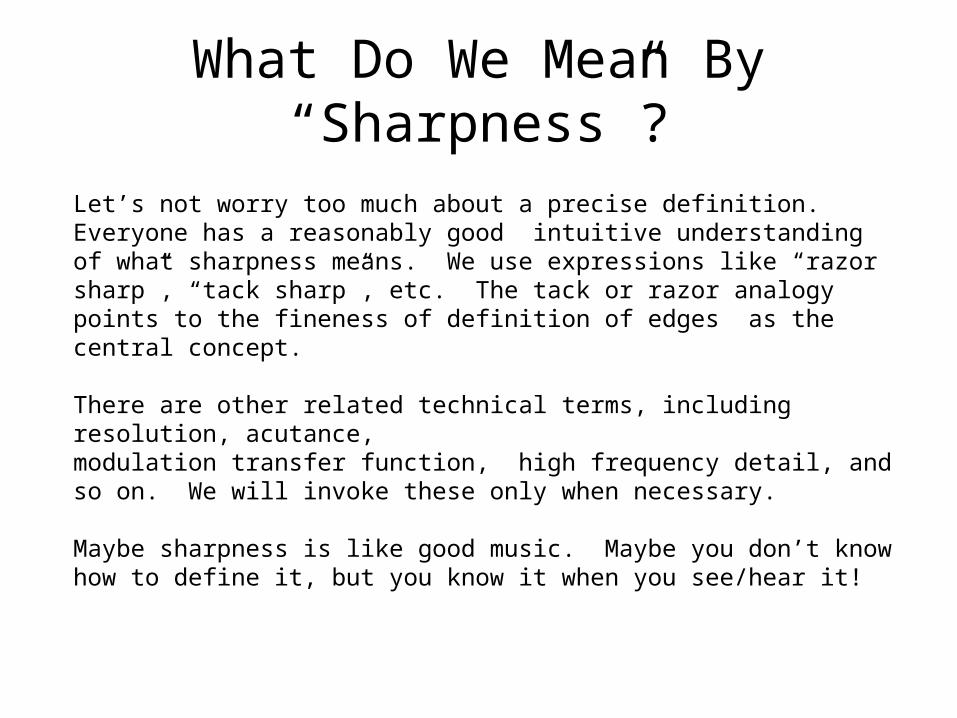
What Do We Mean By “Sharpness”?
Let’s not worry too much about a precise definition. Everyone has a reasonably good intuitive understanding of what sharpness means. We use expressions like “razor sharp”, “tack sharp”, etc. The tack or razor analogy points to the fineness of definition of edges as the central concept.
There are other related technical terms, including resolution, acutance, modulation transfer function, high frequency detail, and so on. We will invoke these only when necessary.
Maybe sharpness is like good music. Maybe you don’t know how to define it, but you know it when you see/hear it!
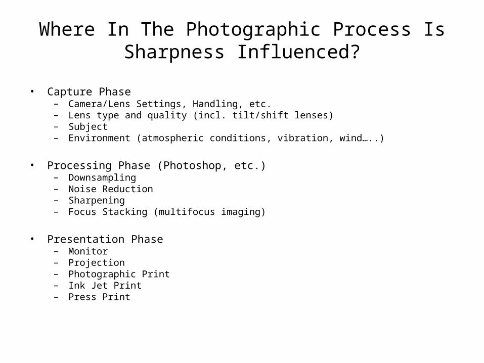
Where In The Photographic Process Is Sharpness Influenced?
• Capture Phase– Camera/Lens Settings, Handling, etc.– Lens type and quality (incl. tilt/shift lenses)– Subject– Environment (atmospheric conditions, vibration, wind…..)
• Processing Phase (Photoshop, etc.)– Downsampling– Noise Reduction– Sharpening– Focus Stacking (multifocus imaging)
• Presentation Phase– Monitor– Projection– Photographic Print– Ink Jet Print– Press Print
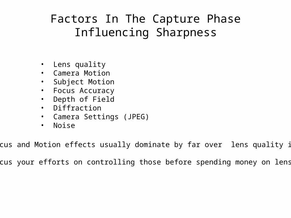
Factors In The Capture Phase Influencing Sharpness
• Lens quality• Camera Motion• Subject Motion• Focus Accuracy• Depth of Field• Diffraction• Camera Settings (JPEG)• Noise
Focus and Motion effects usually dominate by far over lens quality issues.
Focus your efforts on controlling those before spending money on lenses.
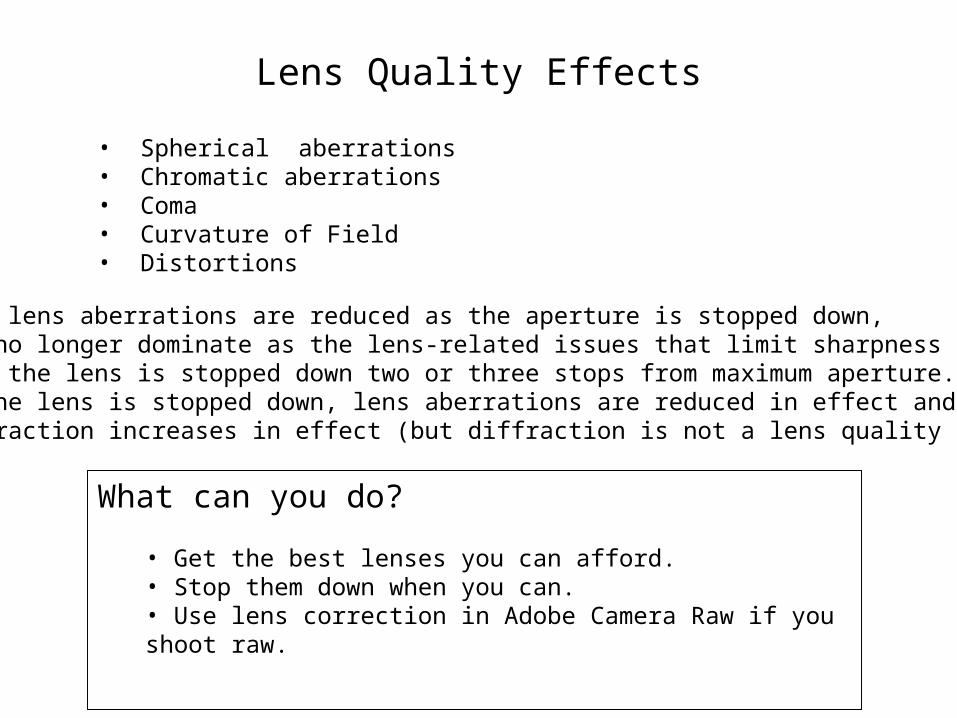
Lens Quality Effects
• Spherical aberrations• Chromatic aberrations• Coma• Curvature of Field• Distortions
Most lens aberrations are reduced as the aperture is stopped down, and no longer dominate as the lens-related issues that limit sharpness when the lens is stopped down two or three stops from maximum aperture. As the lens is stopped down, lens aberrations are reduced in effect anddiffraction increases in effect (but diffraction is not a lens quality issue).
What can you do?
• Get the best lenses you can afford.• Stop them down when you can.• Use lens correction in Adobe Camera Raw if you shoot raw.
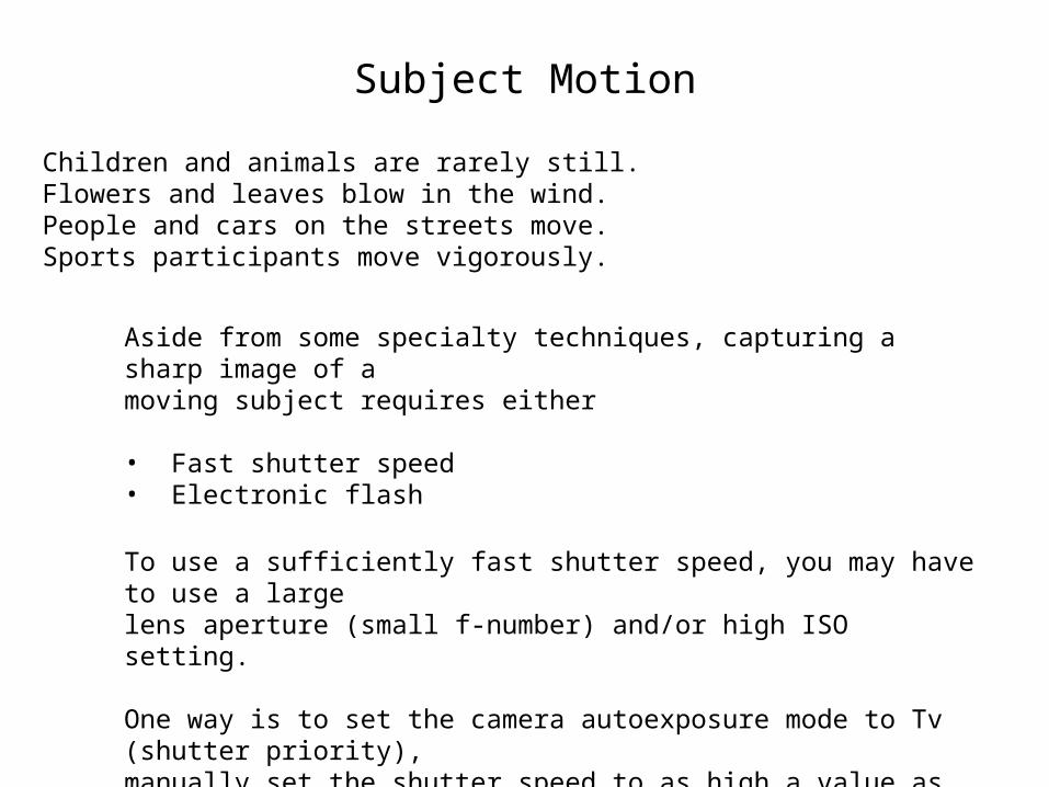
Subject Motion
Children and animals are rarely still.Flowers and leaves blow in the wind.People and cars on the streets move.Sports participants move vigorously.
Aside from some specialty techniques, capturing a sharp image of a moving subject requires either
• Fast shutter speed• Electronic flash
To use a sufficiently fast shutter speed, you may have to use a largelens aperture (small f-number) and/or high ISO setting.
One way is to set the camera autoexposure mode to Tv (shutter priority),manually set the shutter speed to as high a value as necessary, increase the ISO as necessary to achieve an acceptable f-stop setting.
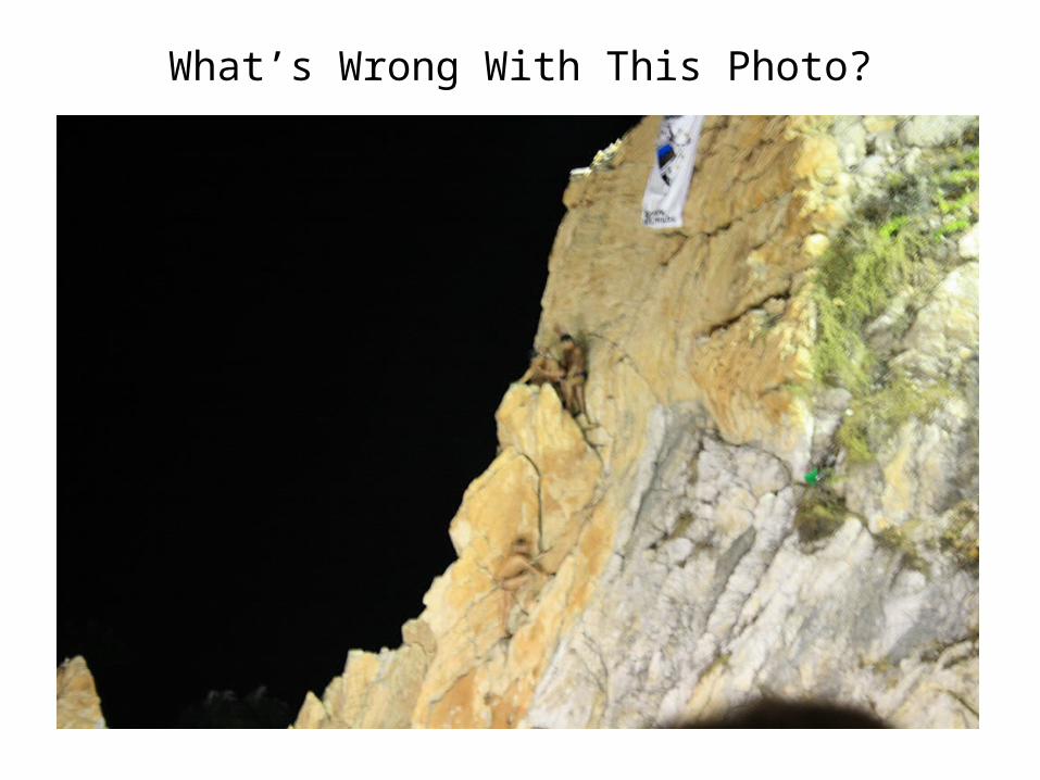
What’s Wrong With This Photo?
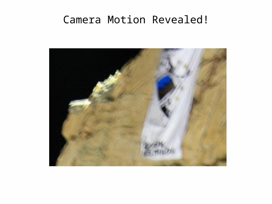
Camera Motion Revealed!
Camera Motion
• Just as with subject motion, camera motion effects can be reduced by using a fast shutter speed and/or electronic flash.
• Stabilization features of the camera or lens are also very beneficial. Image stabilization is a significant advance, providing a 2-3 stop advantage.
• When possible, use a sturdy tripod, even in bright conditions.
• If a tripod is not available or conditions prevent its use, other techniques can be used.
• Brace the camera or your body against a rigid object (even when using a monopod).
• Use a monopod.
• Make a tripod with your two feet and the monopod.
• Use a shoulder against a fixed object plus your two feet arranged as a tripod, aided by the monopod.
• Keep your arms against your body.
• Use a bean-bag-type support.
• When handholding:
• Control your breathing.
• Use a practiced shutter button press.
• Use a shutter speed at least two stops faster than the old rule-of-thumb 1/focal length. With image stabilization, the rule-of-thumb is OK. For the rule, use 35mm equivalent focal length.
Using a Tripod• Use as sturdy a tripod as you can.
– Sturdy = big & heavy, but do what you can.
• Avoid extending the center column when you can, or avoid having a center column.
• Wiggle the feet down into a stable position if in soft dirt, sand, gravel, etc.
• Hang a weight from the center column to stabilize against strong winds.
• If using a DSLR, use remote shutter release, mirror lockup, and 2-second timer.
• If using a compact digicam, use the timer.
• Consider using a custom settings feature of the camera, if available, to configure the camera for tripod use.
– Example: ISO 100, Aperture Priority, Single Shot, Mirror Lock Up, 2-sec Timer
• Lens and camera manufacturers usually recommend disabling image stabilization when using a tripod. It may still be advisable to use it in certain conditions.
Tripod Demo
Focus
• There are two parts to the focus issue:
– Where to focus
– How much should be in acceptable focus and how to achieve that
• Those two issues are not completely separable
• But first, let’s look at some camera techniques for achieving precise focus on a desired point.
Autofocus
• If you are using autofocus, you need to really learn your camera. How does it choose the point to focus on? How can you control what it does?
• Cameras may focus on the nearest object, or the nearest object near a chosen focus point. It may detect faces and focus on one.
• If its logic is too hard to understand and control, set it to focus at the center of the frame and to lock the focus with shutter half-press or other dedicated focus button. You may want to disable face detection, etc. if you can’t predict or control how it behaves.
Manual Focus
• When you set the lens or camera to manual focus, you can precisely control what you focus on and how accurately you focus. This may be more difficult with some compact digicams, but, again, learn your camera.
• For tripod work, manual focus is almost always best, IMO.
• If your DSLR has Live View, with a zoom feature, that is absolutely the best way to achieve precision focus. Use manual focus. Frame your shot, enable Live View, zoom to 10X, focus, turn off Live View (or not, depending on the camera), and shoot. This is best done on a tripod, but can also be effective handheld.
• Demo
• Your compact camera may have a zoom inset during manual focus. Enable it if it is controlled by a menu option.
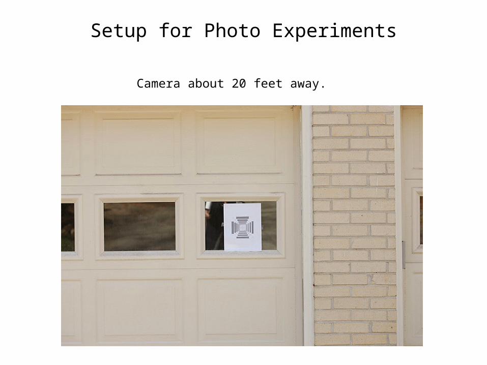
Setup for Photo Experiments
Camera about 20 feet away.
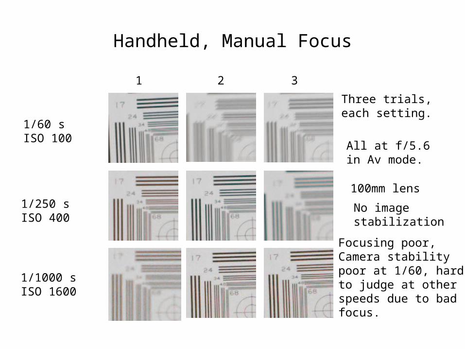
Handheld, Manual Focus
1/60 sISO 100
1/250 sISO 400
1/1000 sISO 1600
All at f/5.6in Av mode.
Three trials,each setting.
1 2 3
100mm lens
Focusing poor,Camera stabilitypoor at 1/60, hardto judge at otherspeeds due to badfocus.
No image stabilization
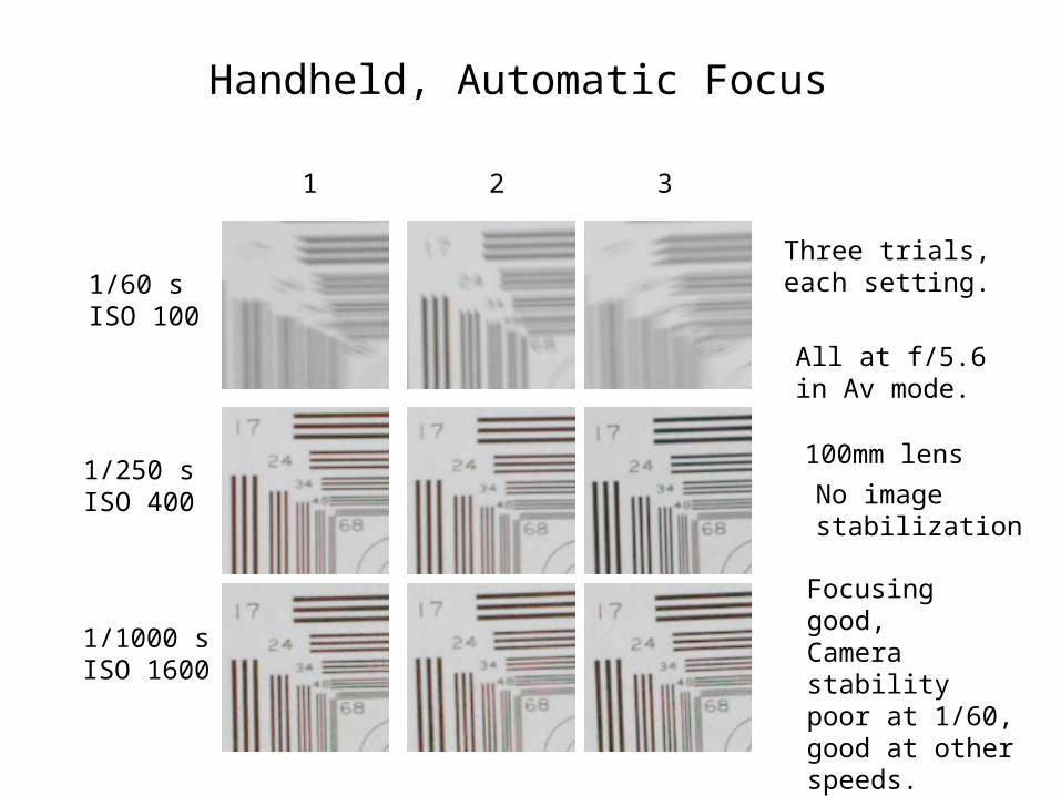
Handheld, Automatic Focus
1/60 sISO 100
1/250 sISO 400
1/1000 sISO 1600
1 2 3
All at f/5.6in Av mode.
Three trials,each setting.
100mm lens
Focusing good,Camera stabilitypoor at 1/60, good at otherspeeds.
No image stabilization
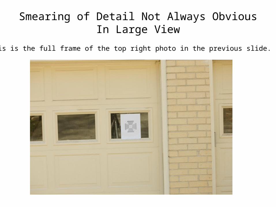
Smearing of Detail Not Always Obvious In Large View
This is the full frame of the top right photo in the previous slide.
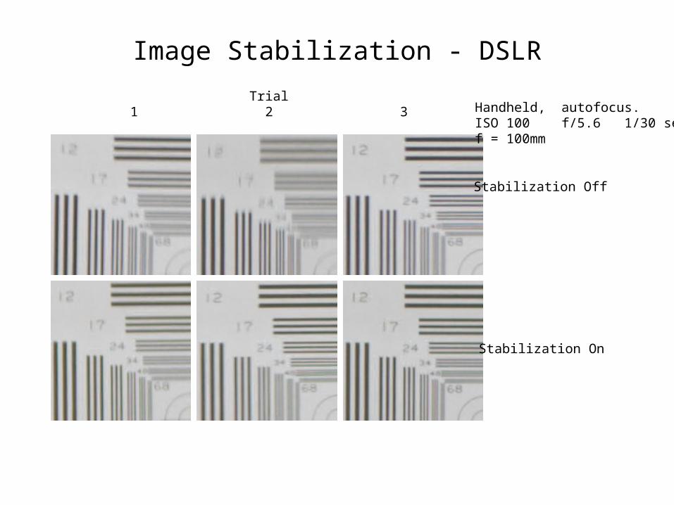
Image Stabilization - DSLR
Handheld, autofocus.ISO 100 f/5.6 1/30 secf = 100mm
Trial1 2 3
Stabilization Off
Stabilization On
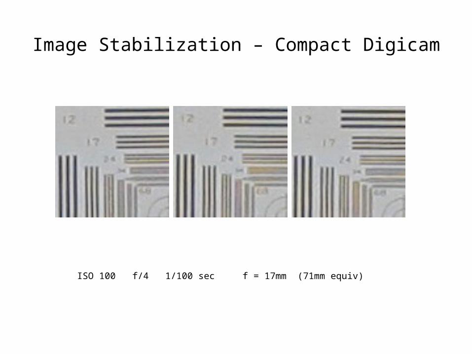
Image Stabilization – Compact Digicam
ISO 100 f/4 1/100 sec f = 17mm (71mm equiv)
Depth of Field
• Objects at only one distance from the camera can be in focus.
• Objects at any other distance will be out of focus and will be blurred (not sharp) to an extent depending on the camera parameters and the distances from the point of perfect focus.
• One can define quantitative criteria for how much Out-Of-Focus (OOF) blurring is acceptable. The OOF limits will be reached at certain knowable distances before and behind the focus point. The difference in distance between these limits is known as Depth of Field (DOF) in subject space (or object space).
• It is sometimes inaccurately stated that all objects inside the DOF are “in focus” and objects outside the DOF are “out of focus”. Actually, everything removed from the plane of perfect focus is OOF; we just decide how much OOF we are willing to tolerate, and that defines our criteria for sharpness and DOF.
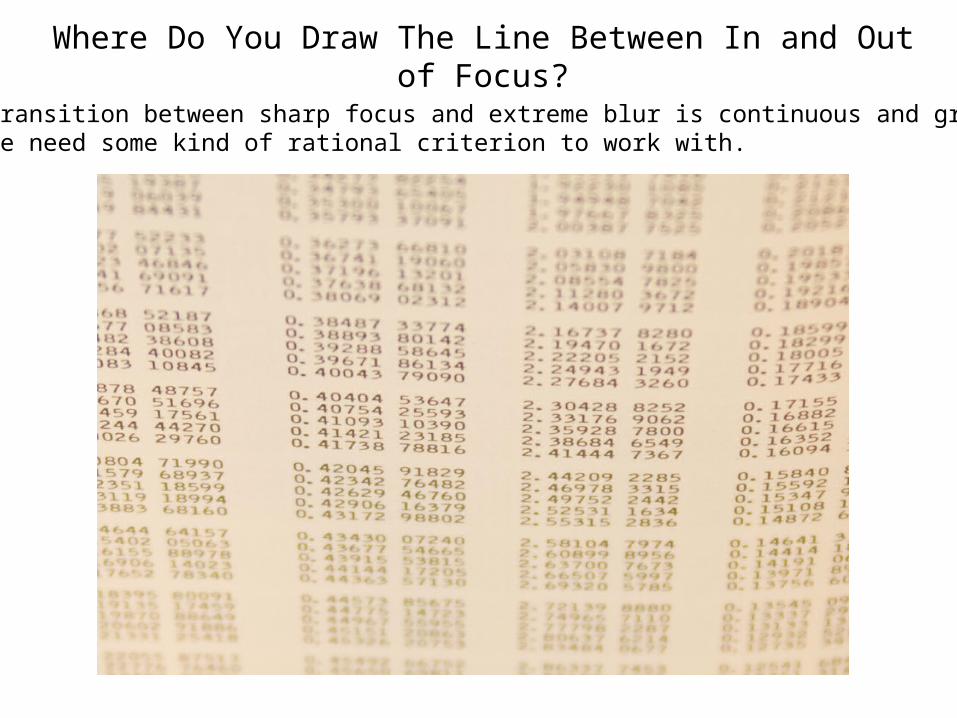
Where Do You Draw The Line Between In and Out of Focus?
The transition between sharp focus and extreme blur is continuous and gradual.But we need some kind of rational criterion to work with.
DOF Criteria
• There is little need to strive for sharpness that is beyond the limits of human visual acuity or beyond the capability of our equipment or media to capture.
• But, in most cases, we likely will want to strive for sufficient sharpness that the important areas of our images are not perceived as unsharp, given how they will be viewed.
• Sharpness criteria definitions have been approached from many directions. We will explore several of these and compare them.
• The two basic approaches have been based on human vision or on capabilities of film.
Human Visual Acuity
• Normal (average) human visual acuity is widely considered to be one minute of arc (1/60 degree)
– Snellen Chart (1862) (20/20 vision)– This is the minimum feature size. Acuity can also be expressed as 30 line pairs
per degree or 30 cycles per degree (cpd)– Depends on lighting, subject contrast, and the individual
• Thus when a person is viewing an image, details which subtend an angle of less than one arcminute will not be perceived. Also, blurring on a scale less than that will also not be perceived and the image will be considered sharp.
• Since the size of the minimum discernable detail depends on the viewing distance, viewing distance becomes a primary factor in defining sharpness criteria.
Viewing Distance
• It is often said that 250 mm (9.8”) is the “normal” viewing distance for an 8X10 inch print.
• Sometimes reference is made to a “comfortable viewing distance”. The closest comfortable viewing distance may also be called the “near distance for distinct vision”.
– Sometimes defined in terms of distance, usually 250mm.– Sometimes defined in terms of angle, often sixty degrees (viewing distance of
11.1” or 282mm for 8x10).• It is also often said that the “normal” viewing distance for a print is equal to
the diagonal dimension of the print, which for an 8X10 inch print is 12.8” or 325 mm.
• Another view is that a print is properly viewed from its “center of perspective” which is the distance at which objects in the print subtend the same angle from the viewer’s eye as those objects did from the camera lens, and the field of view is the same. This distance is equal to the focal length of the taking lens multiplied by the enlargement of the print from the negative, or equivalently, from the image captured by a digital sensor.
– While this may maintain the “apparent perspective” in prints or projected images, it results in awkward distances for images captured with very wide angle or very long telephoto lenses.
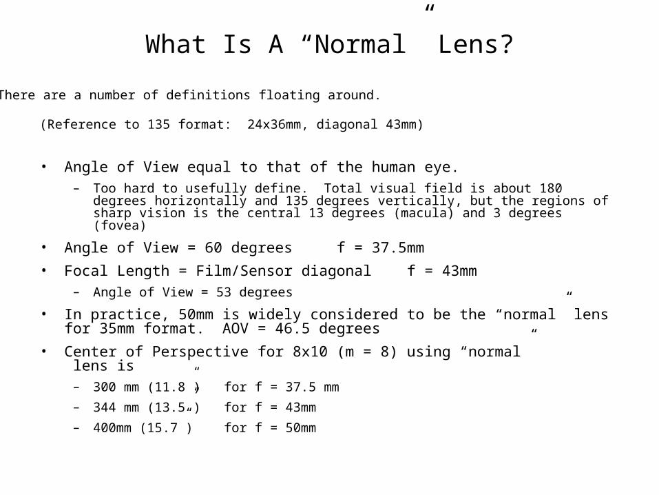
What Is A “Normal” Lens?
(Reference to 135 format: 24x36mm, diagonal 43mm)
• Angle of View equal to that of the human eye. – Too hard to usefully define. Total visual field is about 180 degrees horizontally and 135
degrees vertically, but the regions of sharp vision is the central 13 degrees (macula) and 3 degrees (fovea)
• Angle of View = 60 degrees f = 37.5mm
• Focal Length = Film/Sensor diagonal f = 43mm– Angle of View = 53 degrees
• In practice, 50mm is widely considered to be the “normal” lens for 35mm format. AOV = 46.5 degrees
• Center of Perspective for 8x10 (m = 8) using “normal” lens is
– 300 mm (11.8”) for f = 37.5 mm
– 344 mm (13.5”) for f = 43mm
– 400mm (15.7”) for f = 50mm
There are a number of definitions floating around.
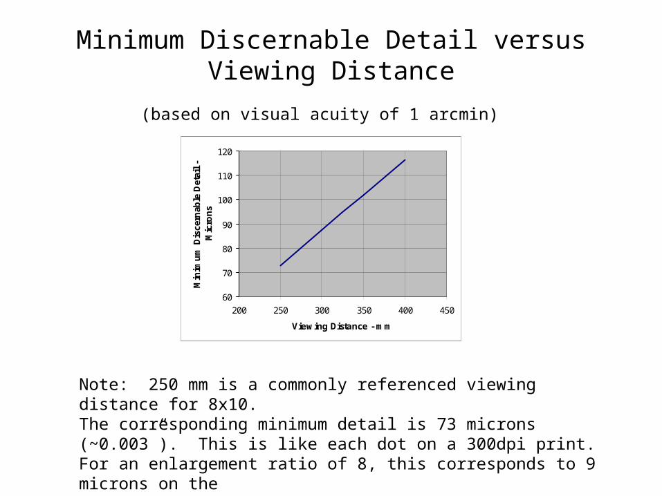
Minimum Discernable Detail versus Viewing Distance
60
70
80
90
100
110
120
200 250 300 350 400 450
Viewing Distance - mm
Min
imu
m D
isce
rnab
le D
etai
l -
Mic
ron
s
(based on visual acuity of 1 arcmin)
Note: 250 mm is a commonly referenced viewing distance for 8x10. The corresponding minimum detail is 73 microns (~0.003”). This is like each dot on a 300dpi print.For an enlargement ratio of 8, this corresponds to 9 microns on the film or sensor, equivalent to 56 lp/mm.
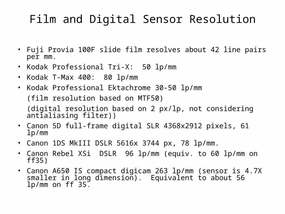
Film and Digital Sensor Resolution
• Fuji Provia 100F slide film resolves about 42 line pairs per mm.
• Kodak Professional Tri-X: 50 lp/mm
• Kodak T-Max 400: 80 lp/mm
• Kodak Professional Ektachrome 30-50 lp/mm
(film resolution based on MTF50)
(digital resolution based on 2 px/lp, not considering antialiasing filter))
• Canon 5D full-frame digital SLR 4368x2912 pixels, 61 lp/mm
• Canon 1DS MkIII DSLR 5616x 3744 px, 78 lp/mm.
• Canon Rebel XSi DSLR 96 lp/mm (equiv. to 60 lp/mm on ff35)
• Canon A650 IS compact digicam 263 lp/mm (sensor is 4.7X smaller in long dimension). Equivalent to about 56 lp/mm on ff 35.
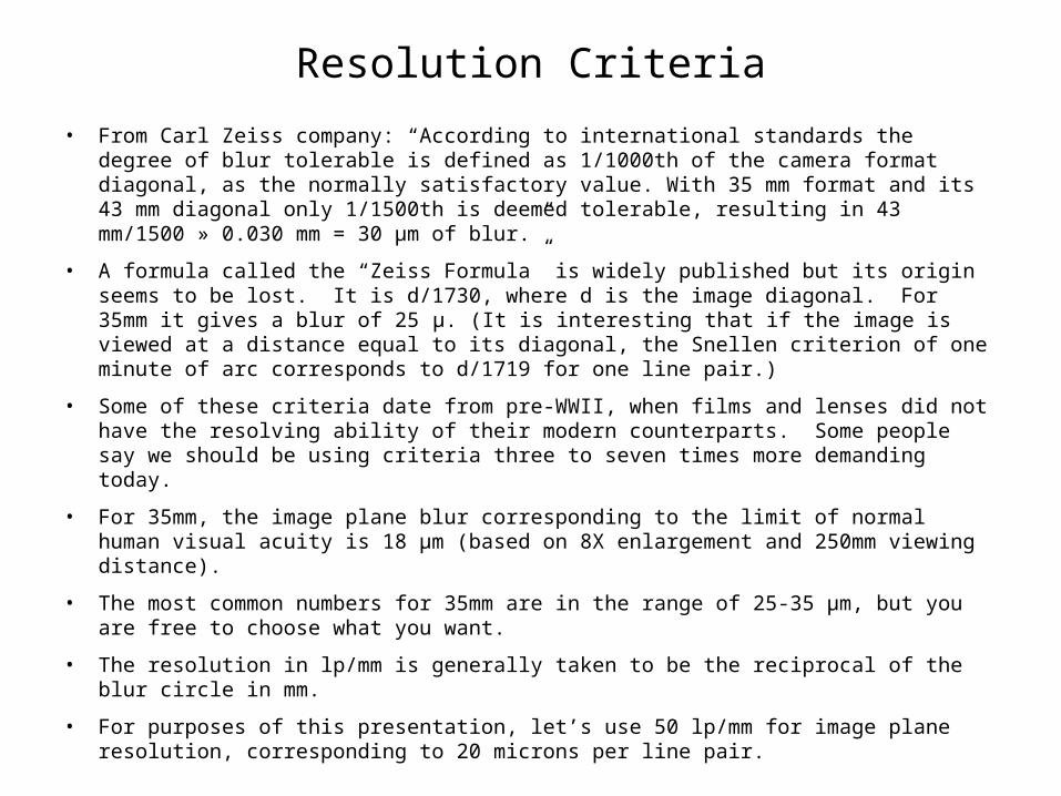
Resolution Criteria
• From Carl Zeiss company: “According to international standards the degree of blur tolerable is defined as 1/1000th of the camera format diagonal, as the normally satisfactory value. With 35 mm format and its 43 mm diagonal only 1/1500th is deemed tolerable, resulting in 43 mm/1500 » 0.030 mm = 30 μm of blur.”
• A formula called the “Zeiss Formula” is widely published but its origin seems to be lost. It is d/1730, where d is the image diagonal. For 35mm it gives a blur of 25 μ. (It is interesting that if the image is viewed at a distance equal to its diagonal, the Snellen criterion of one minute of arc corresponds to d/1719 for one line pair.)
• Some of these criteria date from pre-WWII, when films and lenses did not have the resolving ability of their modern counterparts. Some people say we should be using criteria three to seven times more demanding today.
• For 35mm, the image plane blur corresponding to the limit of normal human visual acuity is 18 μm (based on 8X enlargement and 250mm viewing distance).
• The most common numbers for 35mm are in the range of 25-35 μm, but you are free to choose what you want.
• The resolution in lp/mm is generally taken to be the reciprocal of the blur circle in mm.
• For purposes of this presentation, let’s use 50 lp/mm for image plane resolution, corresponding to 20 microns per line pair.
Effects of Sensor Size
• Images captured by smaller sensors (such as in compact digicams) require greater magnification to final viewing size than for larger sensors.
– Full-frame 35mm: 24x36mm. 1/1.7” sensor: 5.7x7.6mm. 4.2X more magnification required
• Blur circles get magnified as well, so a smaller CoC should be chosen for smaller sensors.
• To maintain an equivalent level of sharpness, the ratio of image height to CoC should be the same for all formats. This is a sharpness quality factor, CoCs per picture height.
– (The same concept applies equally to the final product, whether printed or projected image, as long as viewing distance is also scaled by the same factor.)
– Note that cropping an image reduces the image height but not the CoC, lowering the quality factor.
• To find your sensor size, look in your camera instruction manual under Specifications. If it just says something like 1/1.7”, refer to the table athttp://www.dpreview.com/learn/?/Glossary/Camera_System/sensor_sizes_01.htm
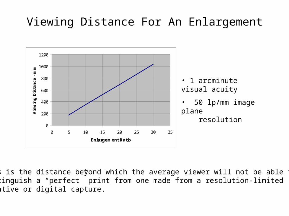
Viewing Distance For An Enlargement
0
200
400
600
800
1000
1200
0 5 10 15 20 25 30 35
Enlargement Ratio
Vie
win
g D
ista
nce
- m
m
• 1 arcminute visual acuity
• 50 lp/mm image plane resolution
This is the distance beyond which the average viewer will not be able to distinguish a “perfect” print from one made from a resolution-limitednegative or digital capture.
Moving On…….
• Now that we have explored some limits on sharpness due to equipment and vision, and how to view our images to avoid seeing those limitations, we can move on to Depth of Field: what it is, how it is controlled, and how we set the criteria for it.
• We will make use of geometrical optics and ray trace diagrams to illustrate the principles involved.
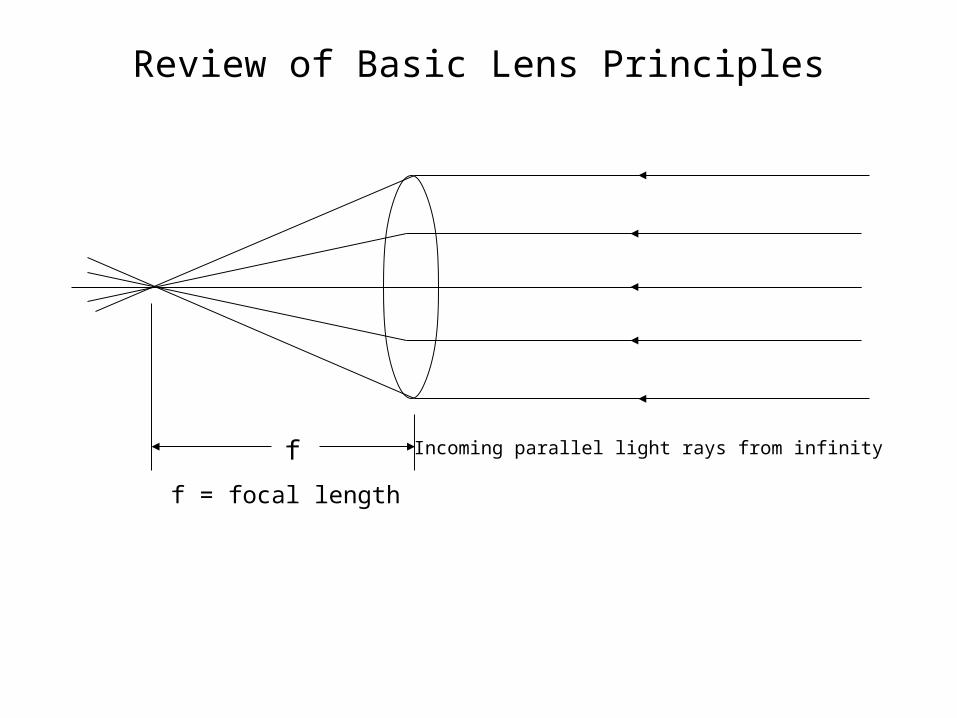
Review of Basic Lens Principles
Incoming parallel light rays from infinityf
f = focal length
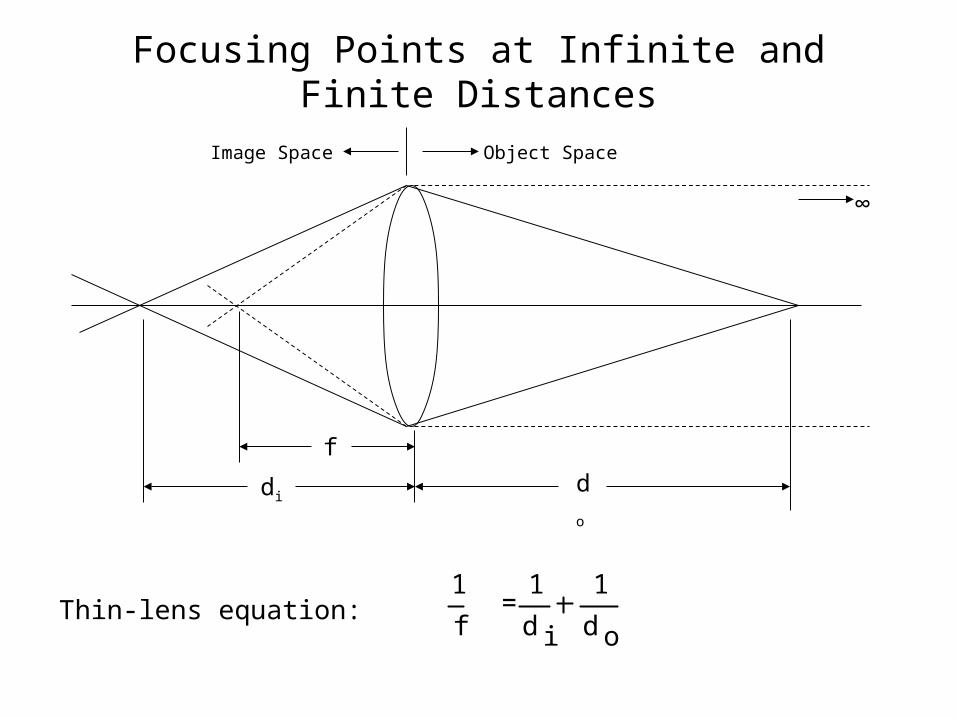
Focusing Points at Infinite and Finite Distances
f
dido
Thin-lens equation:1
f = 1
d i
1
d o
Object SpaceImage Space
∞
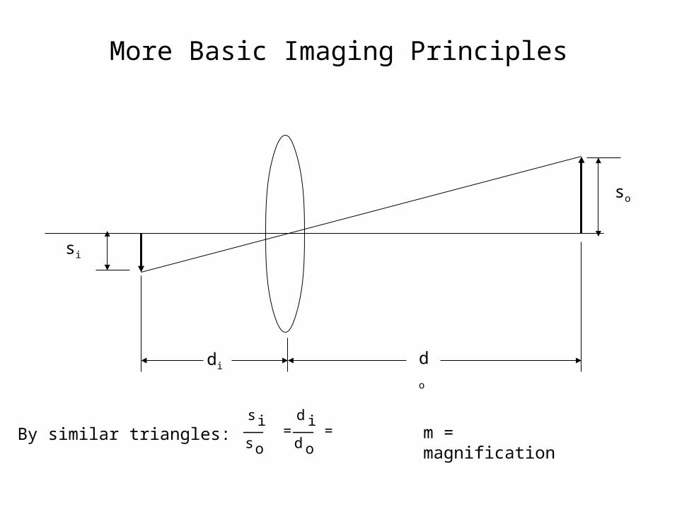
More Basic Imaging Principles
so
si
di do
s i
s o
= d i
d o
= mBy similar triangles: m = magnification
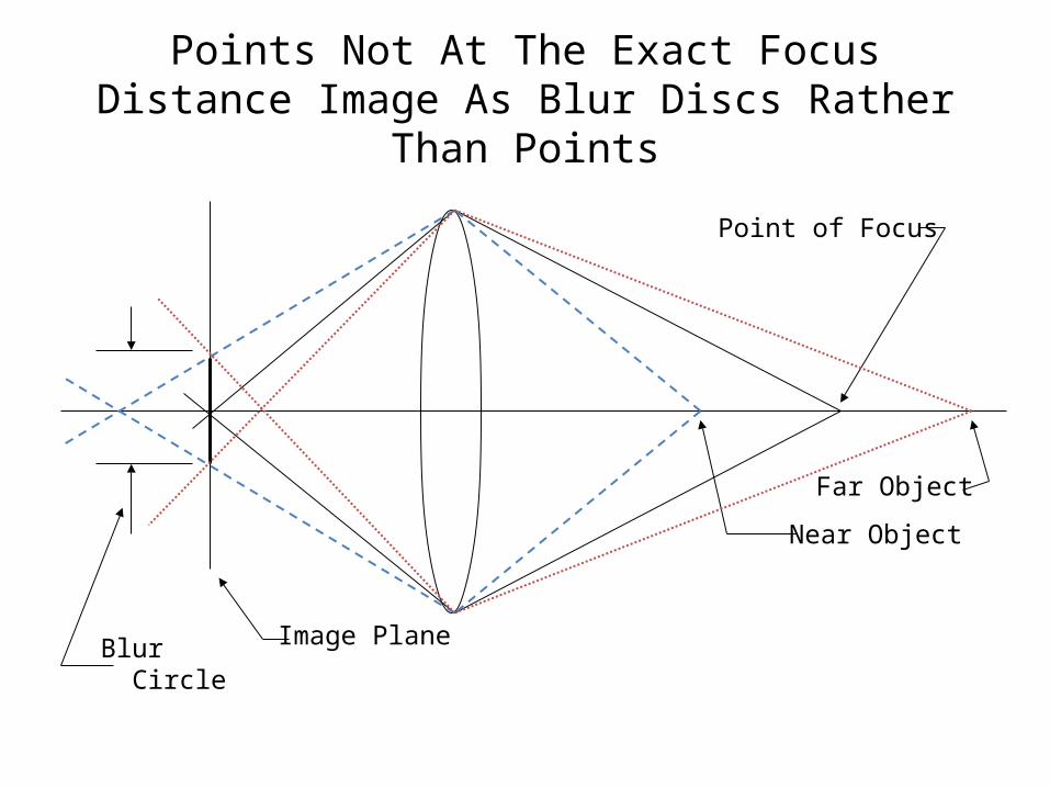
Points Not At The Exact Focus Distance Image As Blur Discs Rather Than Points
Point of Focus
Near Object
Image Plane
Far Object
Blur Circle
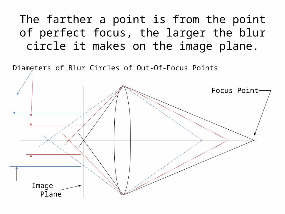
The farther a point is from the point of perfect focus, the larger the blur circle it makes on the
image plane.
Focus Point
Image Plane
Diameters of Blur Circles of Out-Of-Focus Points
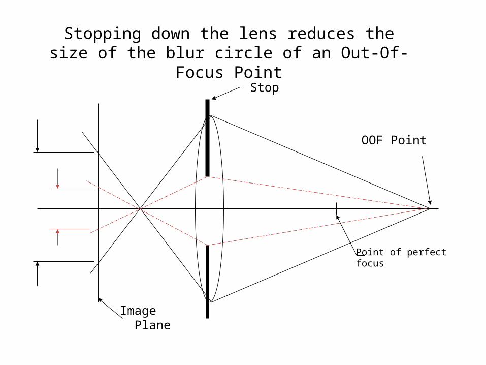
Stop
Image Plane
OOF Point
Stopping down the lens reduces the size of the blur circle of an Out-Of-Focus Point
Point of perfectfocus
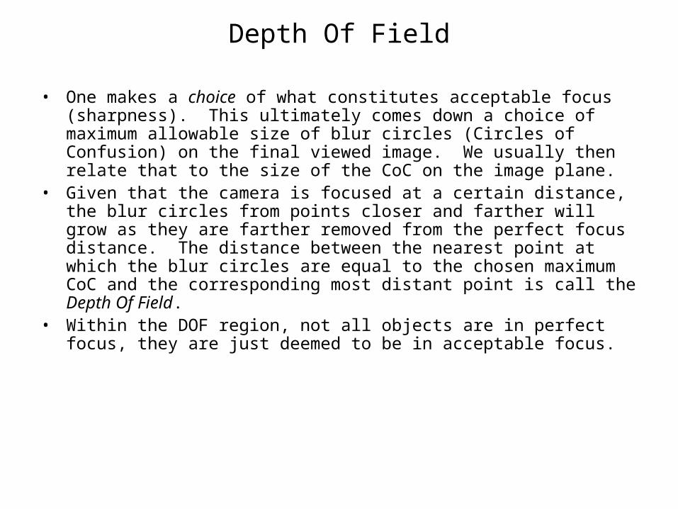
Depth Of Field
• One makes a choice of what constitutes acceptable focus (sharpness). This ultimately comes down a choice of maximum allowable size of blur circles (Circles of Confusion) on the final viewed image. We usually then relate that to the size of the CoC on the image plane.
• Given that the camera is focused at a certain distance, the blur circles from points closer and farther will grow as they are farther removed from the perfect focus distance. The distance between the nearest point at which the blur circles are equal to the chosen maximum CoC and the corresponding most distant point is call the Depth Of Field.
• Within the DOF region, not all objects are in perfect focus, they are just deemed to be in acceptable focus.
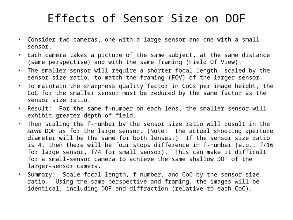
Effects of Sensor Size on DOF
• Consider two cameras, one with a large sensor and one with a small sensor. • Each camera takes a picture of the same subject, at the same distance (same
perspective) and with the same framing (Field Of View). • The smaller sensor will require a shorter focal length, scaled by the sensor size ratio,
to match the framing (FOV) of the larger sensor.• To maintain the sharpness quality factor in CoCs per image height, the CoC for the
smaller sensor must be reduced by the same factor as the sensor size ratio. • Result: For the same f-number on each lens, the smaller sensor will exhibit greater
depth of field.• Then scaling the f-number by the sensor size ratio will result in the same DOF as for
the large sensor. (Note: the actual shooting aperture diameter will be the same for both lenses.) If the sensor size ratio is 4, then there will be four stops difference in f-number (e.g., f/16 for large sensor, f/4 for small sensor). This can make it difficult for a small-sensor camera to achieve the same shallow DOF of the larger-sensor camera.
• Summary: Scale focal length, f-number, and CoC by the sensor size ratio. Using the same perspective and framing, the images will be identical, including DOF and diffraction (relative to each CoC).
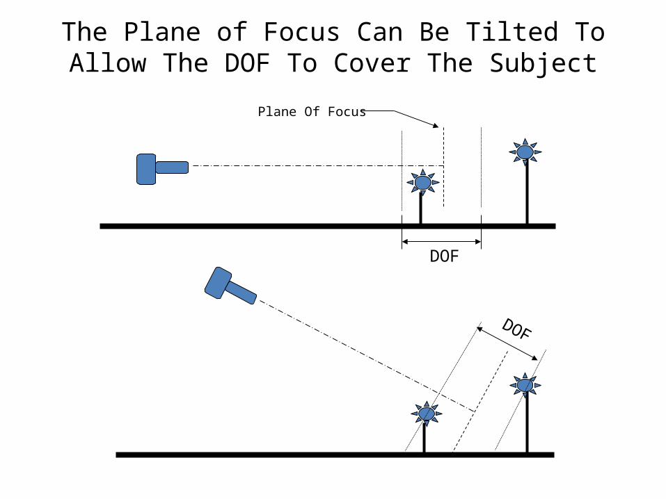
The Plane of Focus Can Be Tilted To Allow The DOF To Cover The Subject
Plane Of Focus
DOF
DOF
DOF Calculations and Charts
• DOF formulae are in abundance on the internet (ask Dr. Google). Or make your own equations, the math is straightforward. With these you can make your own DOF calculator and chart printer.
• There are many ready-made DOF calculators and chart printers as well.
• I like the Bob Atkins calculators
http://bobatkins.com/photography/technical/bokeh_background_blur.html or
http://www.bobatkins.com/photography/technical/depth_of_field_calc.html
• For graphs I like the Nicholas Sushkin programhttp://www.dof.pcraft.com/dof.cgi
• http://toothwalker.org/optics/vwdof.html by Paul van Walree
• An online calculator that will print tables ishttp://www.dofmaster.com/doftable.html
• Jonathan Sachs’ calculator: http://www.dl-c.com/dof.zip . Gives DOF in terms of “lines/mm “, which I think is actually line pairs per mm, and is equal to the reciprocal of the CoC.
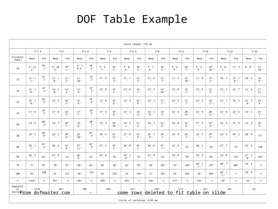
DOF Table Example
Focal Length: 135 mm
f/1.4 f/2 f/2.8 f/4 f/5.6 f/8 f/11 f/16 f/22 f/32
Distance(feet)
Near Far Near Far Near Far Near Far Near Far Near Far Near Far Near Far Near Far Near Far
109' 11.2
''10' 1
''9' 10.9
''10' 1''
9' 10.4''
10' 2''
9' 9.7'' 10' 2'' 9' 8.8'' 10' 3'' 9' 7.6'' 10' 5'' 9' 5.8'' 10' 7'' 9' 3.4''10' 1
0''9' 0.3'' 11' 3'' 8' 8''
11' 10''
1211' 11'
'12' 1
''11' 10'
'12' 2''
11' 10''
12' 2''
11' 9'' 12' 3'' 11' 7'' 12' 5'' 11' 6'' 12' 7'' 11' 3''12' 1
0''11' 0'' 13' 3'' 10' 7''
13' 10''
10' 2'' 14' 9''
1413' 10'
'14' 2
''13' 10'
'14' 2'' 13' 9''
14' 3''
13' 8'' 14' 5'' 13' 6'' 14' 7'' 13' 3''14' 1
0''13' 0'' 15' 2'' 12' 8'' 15' 9'' 12' 2'' 16' 7'' 11' 6''
17' 11''
1615' 10'
'16' 2
''15' 9'' 16' 3'' 15' 8''
16' 4''
15' 6'' 16' 6'' 15' 4'' 16' 9'' 15' 1'' 17' 1'' 14' 8'' 17' 7'' 14' 3'' 18' 3'' 13' 7'' 19' 5''12' 10'
'21' 4''
18 17' 9''18' 3
''17' 8'' 18' 4'' 17' 7''
18' 6''
17' 5'' 18' 8'' 17' 2''18' 1
1''16' 10'
'19' 4'' 16' 4'' 20' 0'' 15' 9''
20' 11''
15' 0'' 22' 6'' 14' 1'' 25' 1''
20 19' 9''20' 3
''19' 7'' 20' 5'' 19' 6''
20' 7''
19' 3''20' 1
0''18' 11'
'21' 2'' 18' 7'' 21' 8'' 18' 0'' 22' 6'' 17' 3'' 23' 9'' 16' 4'' 25' 9'' 15' 3'' 29' 2''
30 29' 5''30' 8
''29' 2''
30' 11''
28' 10''
31' 4''
28' 4''31' 1
1''27' 8'' 32' 9''
26' 10''
34' 1'' 25' 8'' 36' 1'' 24' 3'' 39' 4'' 22' 6'' 45' 2'' 20' 4'' 57'
4038' 11'
'41' 2
''38' 6'' 41' 8''
37' 11''
42' 5''
37' 1'' 43' 5'' 36' 0'' 45' 1'' 34' 6'' 47' 7'' 32' 8'' 52' 30' 4'' 59' 27' 7'' 73' 24' 6'' 110'
50 48' 4'' 52' 47' 8'' 53' 46' 9'' 54' 45' 6'' 56'43' 10'
'58' 41' 9'' 62' 39' 0'' 70' 35' 9'' 83' 32' 0'' 114'
27' 10''
245'
75 71' 79' 70' 81' 68' 84' 65' 88' 62' 95' 58' 107' 53' 130'46' 11'
'187' 40' 7'' 488' 34' 2'' ∞
100 93' 108' 91' 111' 88' 116' 83' 125' 78' 139' 71' 167' 64' 230' 56' 498'46' 11'
'∞ 38' 6'' ∞
∞ 1410' ∞ 997' ∞ 705' ∞ 499' ∞ 353' ∞ 250' ∞ 177' ∞ 125' ∞ 89' ∞ 63' ∞
HyperfocalDistance
1410' 997' 705' 499' 353' 250' 177' 125' 89' 63'
Circle of confusion: 0.03 mm
From dofmaster.com - some rows deleted to fit table on slide
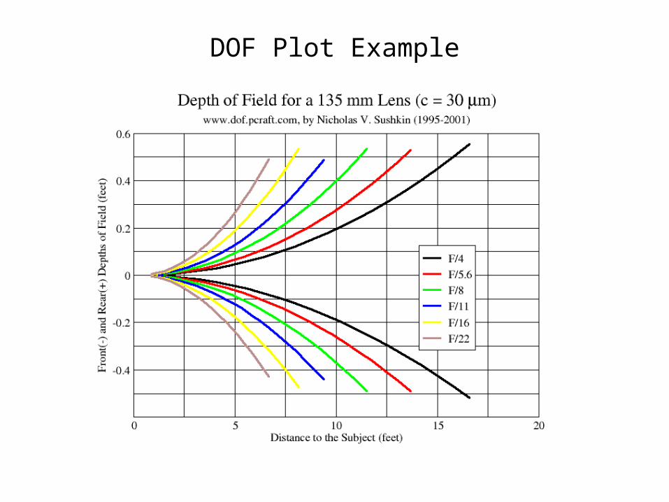
DOF Plot Example
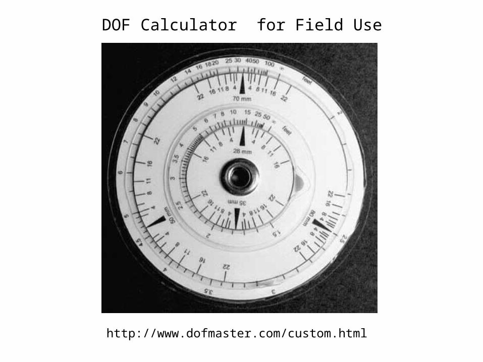
DOF Calculator for Field Use
http://www.dofmaster.com/custom.html
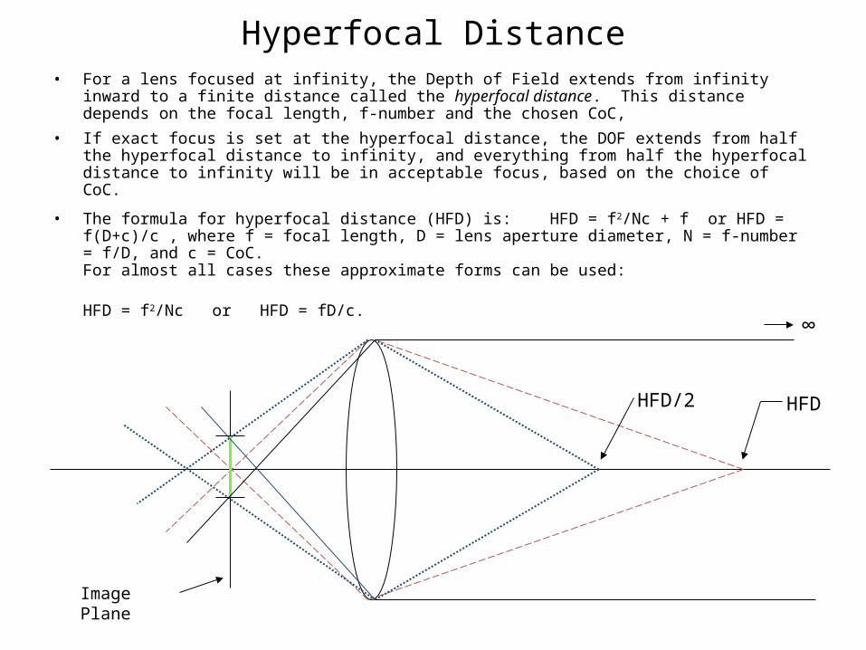
Hyperfocal Distance• For a lens focused at infinity, the Depth of Field extends from infinity inward to a finite distance
called the hyperfocal distance. This distance depends on the focal length, f-number and the chosen CoC,
• If exact focus is set at the hyperfocal distance, the DOF extends from half the hyperfocal distance to infinity, and everything from half the hyperfocal distance to infinity will be in acceptable focus, based on the choice of CoC.
• The formula for hyperfocal distance (HFD) is: HFD = f2/Nc + f or HFD = f(D+c)/c , where f = focal length, D = lens aperture diameter, N = f-number = f/D, and c = CoC. For almost all cases these approximate forms can be used:
HFD = f2/Nc or HFD = fD/c.
Image Plane
HFDHFD/2
∞
Using Hyperfocal Distance
• The hyperfocal technique is normally used when it is desired for the depth of field (based on a chosen CoC) to extend to infinity.
• By consulting hyperfocal distance charts, an f-stop and focus distance is selected so that the near edge of the DOF encompasses the desired subject material, considering the effects of diffraction.
• The sharpest part of the image will be at the hyperfocal distance, growing progressively less sharp as distance from the hyperfocal distance increases.
• Observe, however, that perceived sharpness of a subject will depend on the size of the blur circle relative to the size of the subject, and subject material at great distance has details that are smaller in the image, while the blur circle grows with distance. Thus distant subjects will appear to be much less sharp than near subjects.
• Another characteristic of the hyperfocal distance is that it is the near edge of the DOF when the lens is focused at infinity. Some authors define hyperfocal distance this way. Focusing at infinity will improve perceived sharpness of distant subject material.
Hyperfocal Distance (cont’d)
• Here is still another way to think of hyperfocal distance: With the lens focused at infinity, it is is the distance at which the image magnification is such that the CoC on the image plane corresponds to an object having diameter equal to the lens aperture.
• And a way to remember the formula: Divide the lens aperture diameter by the CoC. That is how many focal lengths are in the hyperfocal distance.
• A hyperfocal distance plotter can be found at http://dofmaster.com/charts.html
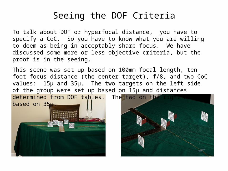
Seeing the DOF Criteria
To talk about DOF or hyperfocal distance, you have to specify a CoC. So you have to know what you are willing to deem as being in acceptably sharp focus. We have discussed some more-or-less objective criteria, but the proof is in the seeing.
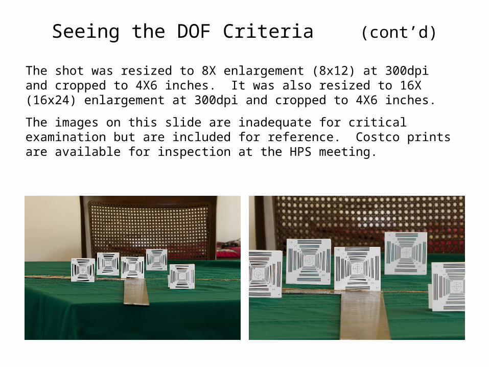
This scene was set up based on 100mm focal length, ten foot focus distance (the center target), f/8, and two CoC values: 15µ and 35µ. The two targets on the left side of the group were set up based on 15µ and distances determined from DOF tables. The two on the right are based on 35µ.
Seeing the DOF Criteria (cont’d)
The shot was resized to 8X enlargement (8x12) at 300dpi and cropped to 4X6 inches. It was also resized to 16X (16x24) enlargement at 300dpi and cropped to 4X6 inches.
The images on this slide are inadequate for critical examination but are included for reference. Costco prints are available for inspection at the HPS meeting.
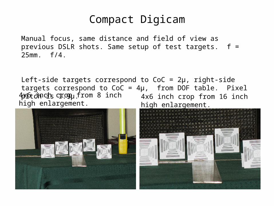
Compact Digicam
4x6 inch crop from 8 inch high enlargement.
4x6 inch crop from 16 inch high enlargement.
Manual focus, same distance and field of view as previous DSLR shots. Same setup of test targets. f = 25mm. f/4.
Left-side targets correspond to CoC = 2µ, right-side targets correspond to CoC = 4µ, from DOF table. Pixel pitch is 1.9µ.
Rant
I have always felt somewhat frustrated by the conventional approach to DOF. It tells you how to set a “region of acceptable focus”, but gives no guidance outside that region. It just sort of leaves you hanging there, twisting slowly in the wind. Many times a solution to a photographic problem cannot be found using standard DOF techniques. The photographer needs more than to have to resort to just guessing. S/He needs to be able to take control of the situation and have sufficient knowledge to make rational tradeoffs and compromises to arrive at an acceptable photographic result. You won’t always be able to get a result that meets your initial expectations, but at least you will be able to know what you will get and how to better balance the compromises.
Another Approach
• One drawback of the hyperfocal method is that it ensures that distant objects are not sharply imaged. This is significant in many cases, especially deep landscapes.
• Close-in objects, usually larger in the image, are often imaged more sharply than they really need to be given their relative importance in the image.
• Another drawback to the conventional method is that it gives no information as to what happens outside the DOF region it defines.
• A different approach was popularized by Harold Merklinger in the early ’90s, and is variously called the “Merklinger Method”, the “Object Field Method”, or the “Subject Field Method”.
• This approach abandons the conventional image field analysis with CoC and depth of field based on CoC limits. Instead, it is based on what minimum discernable detail is required in the object field.
• It is more intuitive and is simpler to use in practice.
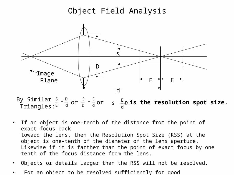
Object Field Analysis
S
D = E
d S
E = D
d
• If an object is one-tenth of the distance from the point of exact focus backtoward the lens, then the Resolution Spot Size (RSS) at the object is one-tenth of the diameter of the lens aperture. Likewise if it is farther than the point of exact focus by one tenth of the focus distance from the lens.
• Objects or details larger than the RSS will not be resolved.
• For an object to be resolved sufficiently for good recognition, the RSS should be 3-5 times smaller than the object.
D
d
E
S
Image Plane
orBy Similar Triangles:
S is the resolution spot size.or
E
S = E
dD
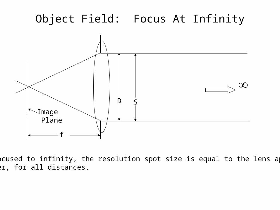
Object Field: Focus At Infinity
D
Image Plane
S
f
When focused to infinity, the resolution spot size is equal to the lens aperturediameter, for all distances.
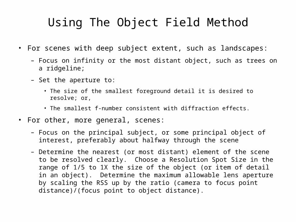
Using The Object Field Method
• For scenes with deep subject extent, such as landscapes:
– Focus on infinity or the most distant object, such as trees on a ridgeline;
– Set the aperture to:
• The size of the smallest foreground detail it is desired to resolve; or,
• The smallest f-number consistent with diffraction effects.
• For other, more general, scenes:
– Focus on the principal subject, or some principal object of interest, preferably about halfway through the scene
– Determine the nearest (or most distant) element of the scene to be resolved clearly. Choose a Resolution Spot Size in the range of 1/5 to 1X the size of the object (or item of detail in an object). Determine the maximum allowable lens aperture by scaling the RSS up by the ratio (camera to focus point distance)/(focus point to object distance).
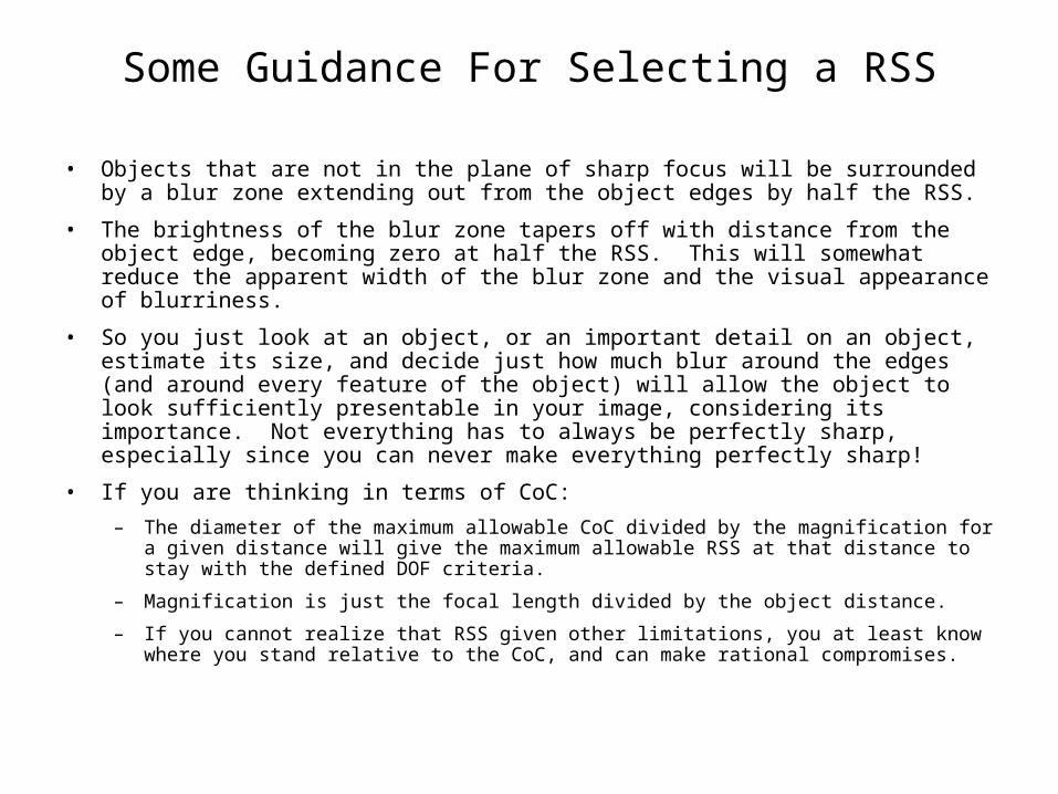
Some Guidance For Selecting a RSS
• Objects that are not in the plane of sharp focus will be surrounded by a blur zone extending out from the object edges by half the RSS.
• The brightness of the blur zone tapers off with distance from the object edge, becoming zero at half the RSS. This will somewhat reduce the apparent width of the blur zone and the visual appearance of blurriness.
• So you just look at an object, or an important detail on an object, estimate its size, and decide just how much blur around the edges (and around every feature of the object) will allow the object to look sufficiently presentable in your image, considering its importance. Not everything has to always be perfectly sharp, especially since you can never make everything perfectly sharp!
• If you are thinking in terms of CoC:
– The diameter of the maximum allowable CoC divided by the magnification for a given distance will give the maximum allowable RSS at that distance to stay with the defined DOF criteria.
– Magnification is just the focal length divided by the object distance.
– If you cannot realize that RSS given other limitations, you at least know where you stand relative to the CoC, and can make rational compromises.
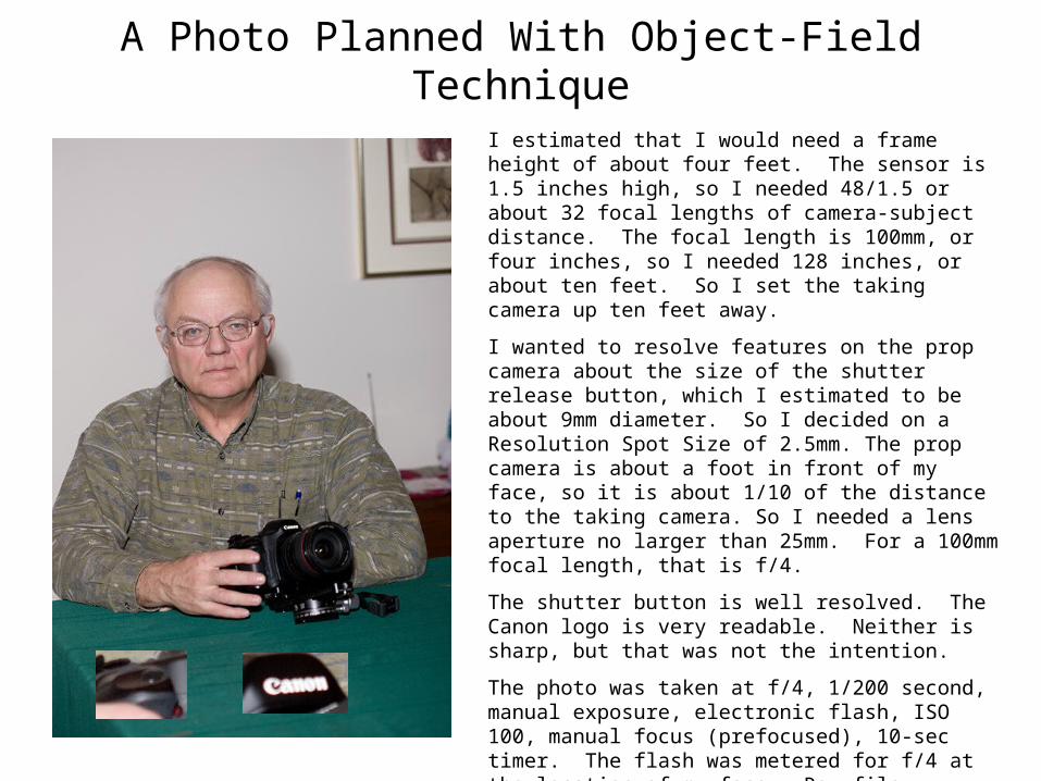
A Photo Planned With Object-Field Technique
I estimated that I would need a frame height of about four feet. The sensor is 1.5 inches high, so I needed 48/1.5 or about 32 focal lengths of camera-subject distance. The focal length is 100mm, or four inches, so I needed 128 inches, or about ten feet. So I set the taking camera up ten feet away.
I wanted to resolve features on the prop camera about the size of the shutter release button, which I estimated to be about 9mm diameter. So I decided on a Resolution Spot Size of 2.5mm. The prop camera is about a foot in front of my face, so it is about 1/10 of the distance to the taking camera. So I needed a lens aperture no larger than 25mm. For a 100mm focal length, that is f/4.
The shutter button is well resolved. The Canon logo is very readable. Neither is sharp, but that was not the intention.
The photo was taken at f/4, 1/200 second, manual exposure, electronic flash, ISO 100, manual focus (prefocused), 10-sec timer. The flash was metered for f/4 at the location of my face. Raw file developed in Adobe Camera Raw at default settings, no postprocessing other than resizing (no cropping).
No charts, no graphs, no CoC. All simple mental calculations based on what I wanted in object space.
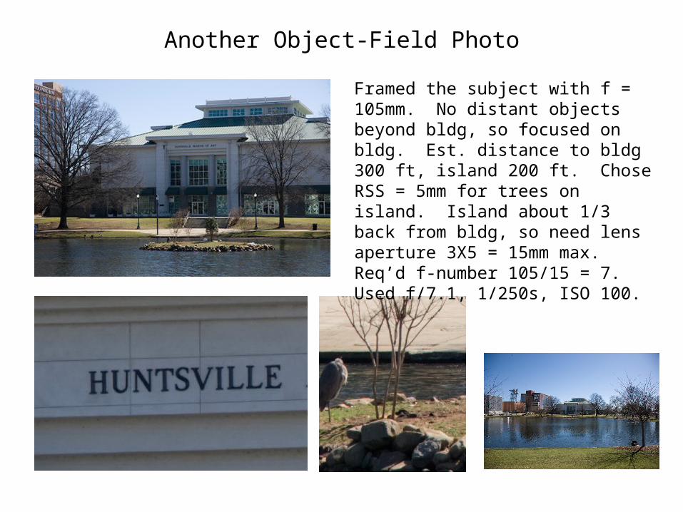
Another Object-Field Photo
Framed the subject with f = 105mm. No distant objects beyond bldg, so focused on bldg. Est. distance to bldg 300 ft, island 200 ft. Chose RSS = 5mm for trees on island. Island about 1/3 back from bldg, so need lens aperture 3X5 = 15mm max. Req’d f-number 105/15 = 7. Used f/7.1, 1/250s, ISO 100.
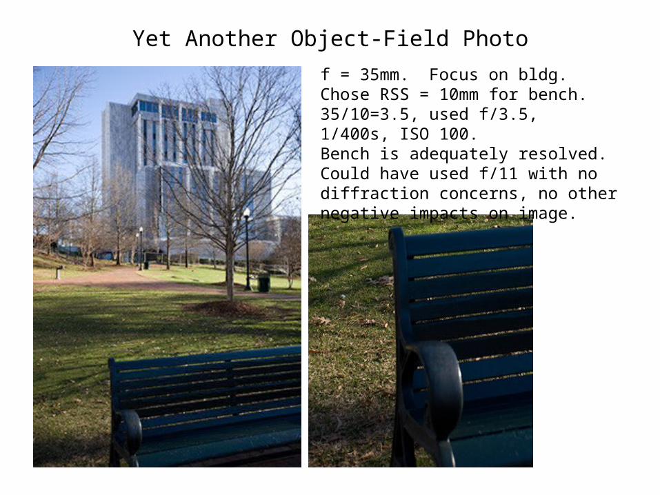
Yet Another Object-Field Photo
f = 35mm. Focus on bldg. Chose RSS = 10mm for bench. 35/10=3.5, used f/3.5, 1/400s, ISO 100.Bench is adequately resolved. Could have used f/11 with no diffraction concerns, no other negative impacts on image.
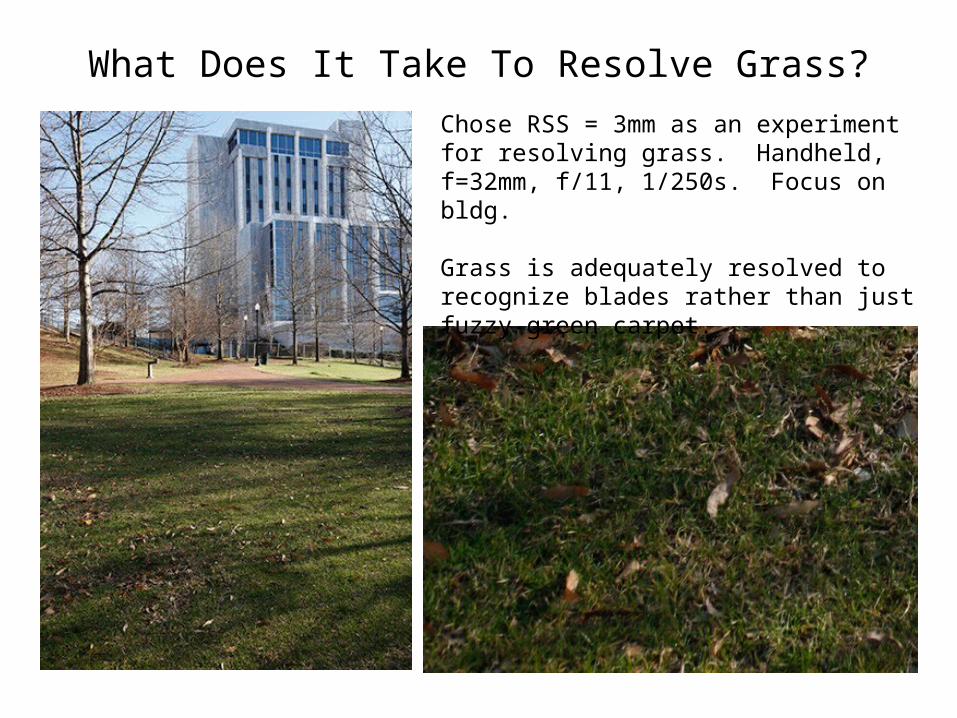
What Does It Take To Resolve Grass?
Chose RSS = 3mm as an experiment for resolving grass. Handheld, f=32mm, f/11, 1/250s. Focus on bldg.
Grass is adequately resolved to recognize blades rather than just fuzzy green carpet.
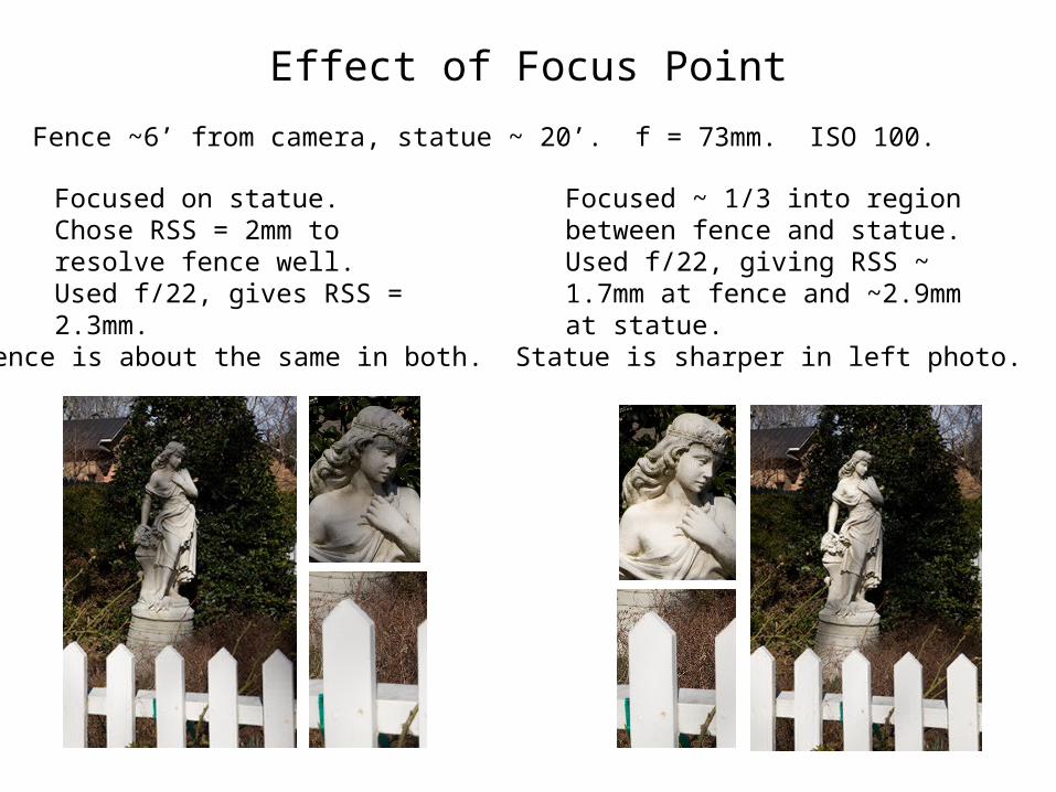
Effect of Focus Point
Fence ~6’ from camera, statue ~ 20’. f = 73mm. ISO 100.
Focused on statue. Chose RSS = 2mm to resolve fence well. Used f/22, gives RSS = 2.3mm.
Focused ~ 1/3 into region between fence and statue. Used f/22, giving RSS ~ 1.7mm at fence and ~2.9mm at statue.
Fence is about the same in both. Statue is sharper in left photo.
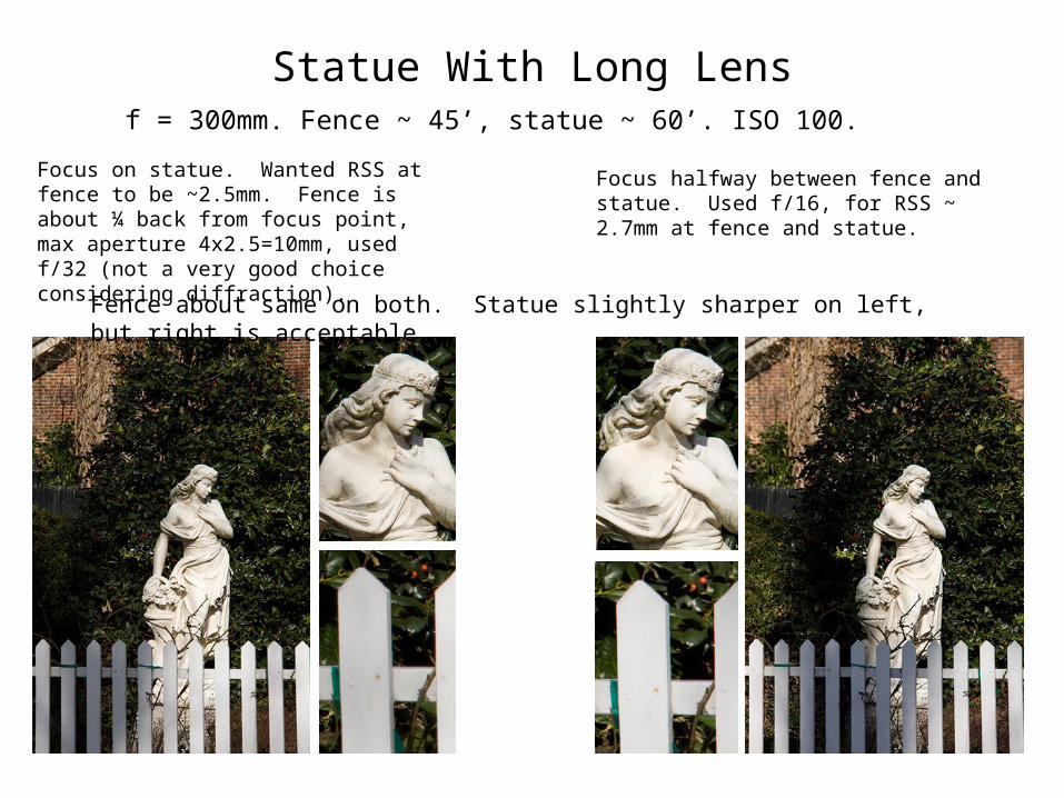
Statue With Long Lensf = 300mm. Fence ~ 45’, statue ~ 60’. ISO 100.
Focus on statue. Wanted RSS at fence to be ~2.5mm. Fence is about ¼ back from focus point, max aperture 4x2.5=10mm, used f/32 (not a very good choice considering diffraction).
Focus halfway between fence and statue. Used f/16, for RSS ~ 2.7mm at fence and statue.
Fence about same on both. Statue slightly sharper on left, but right is acceptable.
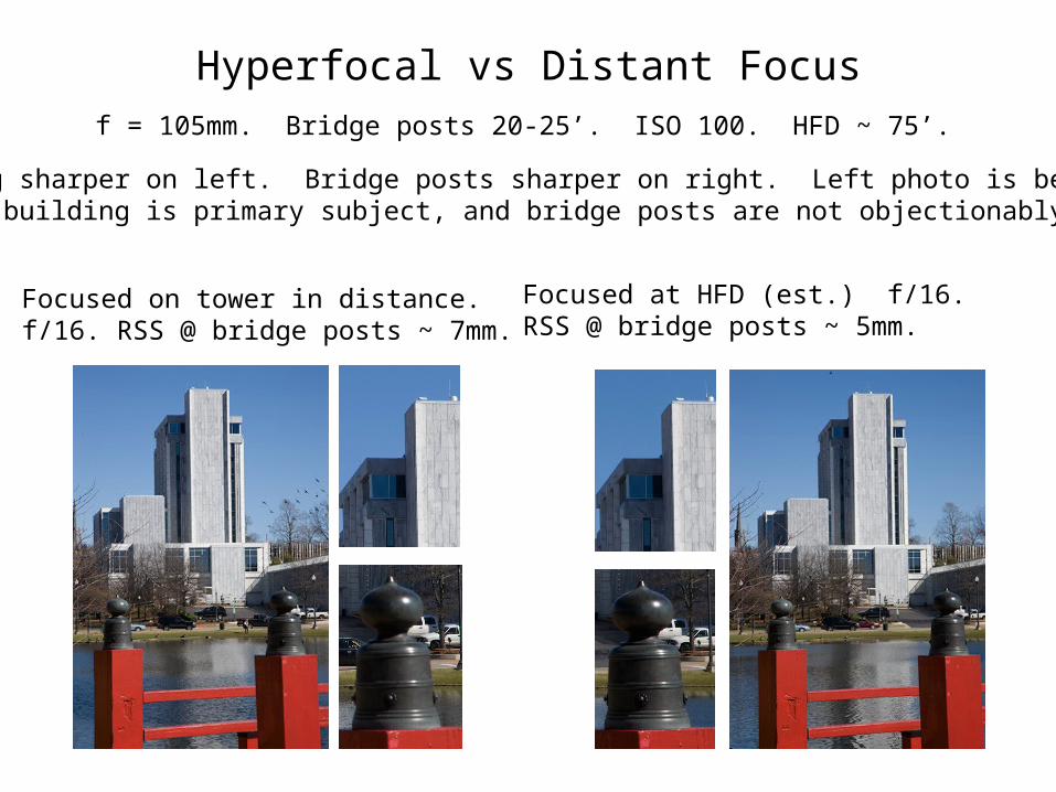
Hyperfocal vs Distant Focusf = 105mm. Bridge posts 20-25’. ISO 100. HFD ~ 75’.
Focused on tower in distance.f/16. RSS @ bridge posts ~ 7mm.
Focused at HFD (est.) f/16. RSS @ bridge posts ~ 5mm.
Building sharper on left. Bridge posts sharper on right. Left photo is betterbecause building is primary subject, and bridge posts are not objectionablyunsharp.
Another Minor Rant
• All information I have been able to find about DOF and Object Resolution seem to talk about either technique, never both. It is like they are treated as two separate bodies of knowledge, never to overlap, and like they obey different physical laws or something.
• In fact, they are the same thing, just being looked at from different sides of the lens. They obey the same laws, and are highly complementary.
• Using object-field methods can fill in the voids in classical DOF methods, providing insight into what happens outside the defined DOF region.
• Not being able to find any coherent discussion relating the two approaches, I set out to unify them.
Unification: Image Field and Object Field
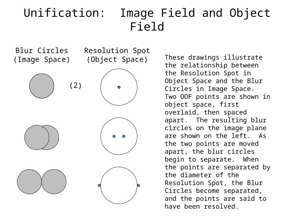
Blur Circles(Image Space)
Resolution Spot(Object Space) These drawings illustrate the
relationship between the Resolution Spot in Object Space and the Blur Circles in Image Space. Two OOF points are shown in object space, first overlaid, then spaced apart. The resulting blur circles on the image plane are shown on the left. As the two points are moved apart, the blur circles begin to separate. When the points are separated by the diameter of the Resolution Spot, the Blur Circles become separated, and the points are said to have been resolved.
(2)
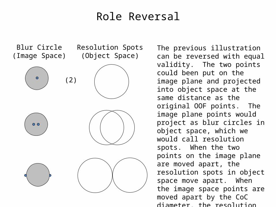
Role Reversal
The previous illustration can be reversed with equal validity. The two points could been put on the image plane and projected into object space at the same distance as the original OOF points. The image plane points would project as blur circles in object space, which we would call resolution spots. When the two points on the image plane are moved apart, the resolution spots in object space move apart. When the image space points are moved apart by the CoC diameter, the resolution spots in object space are just separated, and the points are said to have been resolved.
Blur Circle(Image Space)
Resolution Spots(Object Space)
(2)
Unification: Back and Forth
• Let’s work back and forth across the lens, between object space and image space.
• Consider a lens and image plane, focused at some distance df in object space. Now consider a point on the optical axis in object space, at some other distance, do, where the subscript “o” indicates “out” of focus. This OOF point will image as a disc, or blur circle, on the image plane. Let’s call this the Circle of Confusion, having diameter dc.
• Now let’s turn it around. Consider a point on the optical axis at the image plane. This will image in object space as a point at df, but as a disc at do. The disc is called the Resolution Spot, and its diameter is called the Resolution Spot Size, or RSS.
• Both the CoC and the Resolution Spot are sharp-edged discs.
• Now let’s consider the Resolution Spot in object space, and look at its image on the image plane. It is not at the proper focus distance to render a sharp image. It images as a disc of diameter dc, but with a blur zone around it having width equal to half of dc.
• Again, let’s turn it around. Consider the CoC on the image plane, with sharp edges. This projects into object space at distance do as a Resolution Spot, but with a blur zone around its edges of width equal to half the RSS.
• The presence of the blur zone around an OOF object makes it appear to be larger. The more OOF it is, the larger it looks.
Back and Forth (cont’d)
• The Resolution Spot Size can be considered to be the object space equivalent of the Circle of Confusion in image space. This is more of a usage-based concept rather than a mathematically correct concept. RSS and CoC are not the same thing, but are used for about the same purpose.
• It may seem inconsistent that the Resolution zone (defined by equal Resolution Spot Sizes on each side of the focus distance, in object space) is symmetrical about the focus distance, but the Depth of Field (defined by the point blur circle being not larger than a chosen Circle of Confusion size, in image space) is asymmetrical, having greater extent on the far side.
– RSS varies linearly and symmetrically about the focus point, in object space. Point blur circle diameter varies linearly and symmetrically with focus distance from the image plane, in image space. Distances on one side of the lens are transformed to distances on the other side of the lens by the nonlinear lens equation, causing what is linear and symmetric on one side to become nonlinear and asymmetric on the other side.
• It is easy to relate RSS (object space) to blur circle diameter (image space).
– The relationship is through the magnification, which is simply the ratio of image size to object size, and is equal to the ratio of the object-space distance to the focal length (to a good approximation for distance of more than 10 or so focal lengths). Example follows.
Back and Forth (cont’d)
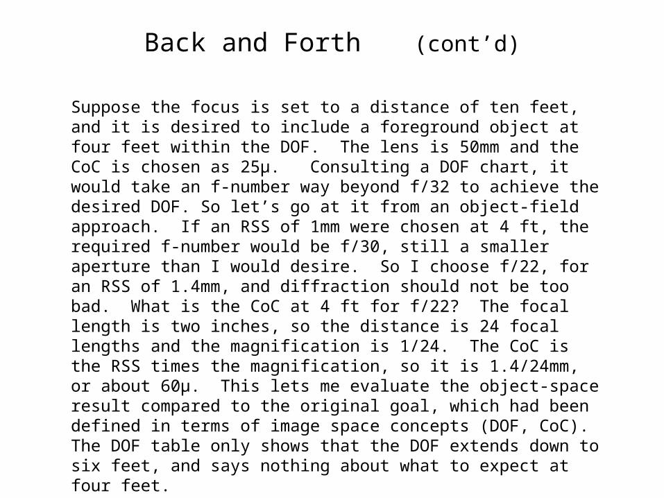
Suppose the focus is set to a distance of ten feet, and it is desired to include a foreground object at four feet within the DOF. The lens is 50mm and the CoC is chosen as 25μ. Consulting a DOF chart, it would take an f-number way beyond f/32 to achieve the desired DOF. So let’s go at it from an object-field approach. If an RSS of 1mm were chosen at 4 ft, the required f-number would be f/30, still a smaller aperture than I would desire. So I choose f/22, for an RSS of 1.4mm, and diffraction should not be too bad. What is the CoC at 4 ft for f/22? The focal length is two inches, so the distance is 24 focal lengths and the magnification is 1/24. The CoC is the RSS times the magnification, so it is 1.4/24mm, or about 60μ. This lets me evaluate the object-space result compared to the original goal, which had been defined in terms of image space concepts (DOF, CoC). The DOF table only shows that the DOF extends down to six feet, and says nothing about what to expect at four feet.
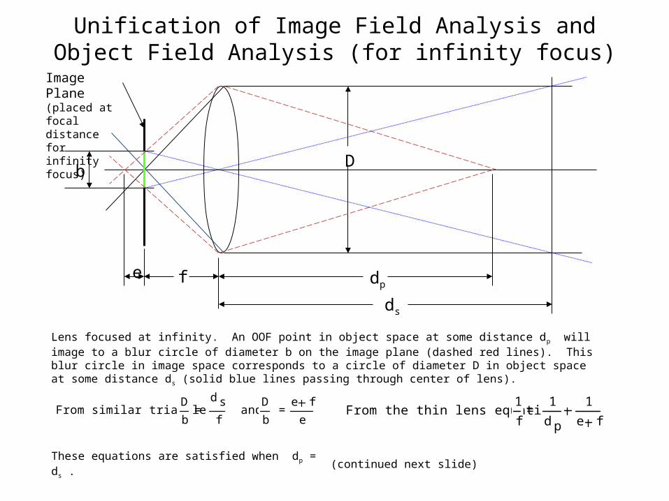
Unification of Image Field Analysis and Object Field Analysis (for infinity focus)
From similar triangles: D
b =
d s
f and D
b = e f
e
These equations are satisfied when dp = ds .
From the thin lens equation: 1
f = 1
d p
1
e f
Image Plane (placed at focal distance for infinity focus)
f
D
e dp
b
ds
Lens focused at infinity. An OOF point in object space at some distance dp will image to a blur circle of diameter b on the image plane (dashed red lines). This blur circle in image space corresponds to a circle of diameter D in object space at some distance ds (solid blue lines passing through center of lens).
(continued next slide)
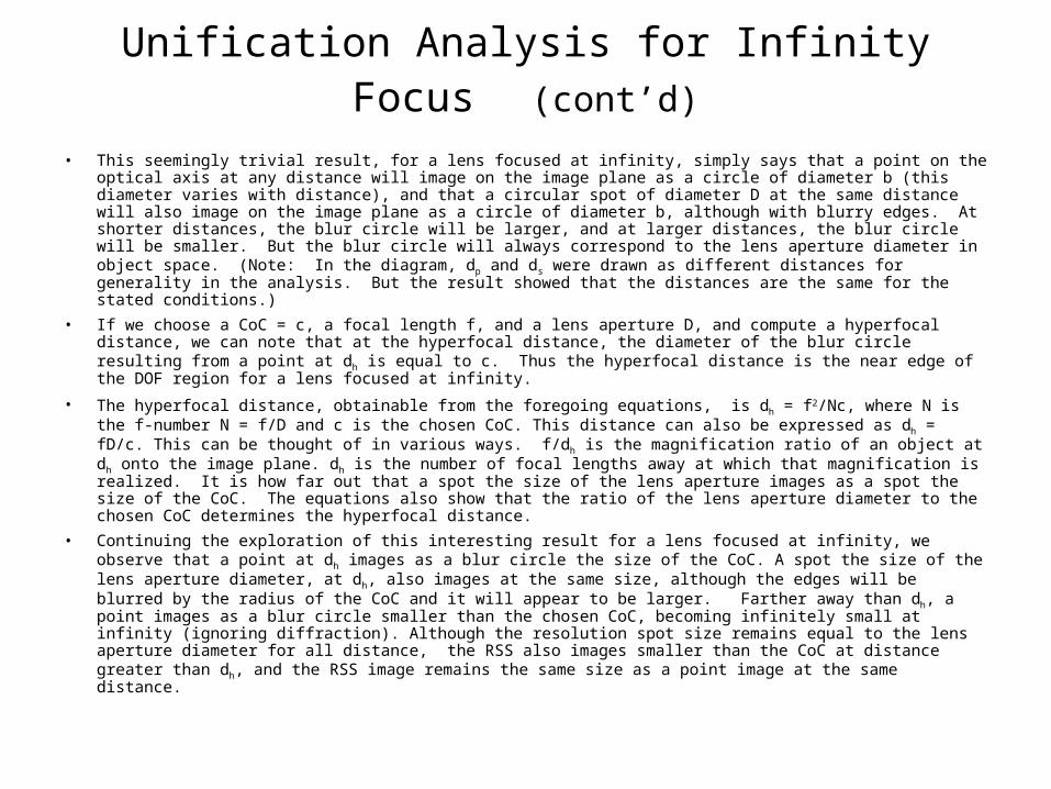
Unification Analysis for Infinity Focus (cont’d)
• This seemingly trivial result, for a lens focused at infinity, simply says that a point on the optical axis at any distance will image on the image plane as a circle of diameter b (this diameter varies with distance), and that a circular spot of diameter D at the same distance will also image on the image plane as a circle of diameter b, although with blurry edges. At shorter distances, the blur circle will be larger, and at larger distances, the blur circle will be smaller. But the blur circle will always correspond to the lens aperture diameter in object space. (Note: In the diagram, dp and ds were drawn as different distances for generality in the analysis. But the result showed that the distances are the same for the stated conditions.)
• If we choose a CoC = c, a focal length f, and a lens aperture D, and compute a hyperfocal distance, we can note that at the hyperfocal distance, the diameter of the blur circle resulting from a point at dh is equal to c. Thus the hyperfocal distance is the near edge of the DOF region for a lens focused at infinity.
• The hyperfocal distance, obtainable from the foregoing equations, is dh = f2/Nc, where N is the f-number N = f/D and c is the chosen CoC. This distance can also be expressed as dh = fD/c. This can be thought of in various ways. f/dh is the magnification ratio of an object at dh onto the image plane. dh is the number of focal lengths away at which that magnification is realized. It is how far out that a spot the size of the lens aperture images as a spot the size of the CoC. The equations also show that the ratio of the lens aperture diameter to the chosen CoC determines the hyperfocal distance.
• Continuing the exploration of this interesting result for a lens focused at infinity, we observe that a point at dh images as a blur circle the size of the CoC. A spot the size of the lens aperture diameter, at dh, also images at the same size, although the edges will be blurred by the radius of the CoC and it will appear to be larger. Farther away than dh, a point images as a blur circle smaller than the chosen CoC, becoming infinitely small at infinity (ignoring diffraction). Although the resolution spot size remains equal to the lens aperture diameter for all distance, the RSS also images smaller than the CoC at distance greater than dh, and the RSS image remains the same size as a point image at the same distance.
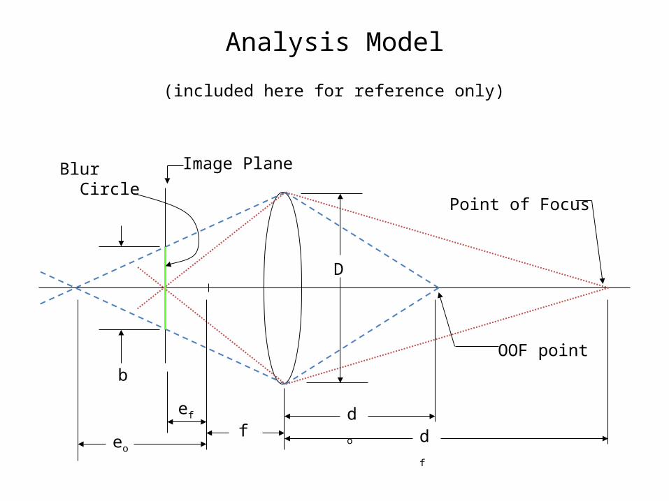
Analysis Model
Point of Focus
OOF point
Image PlaneBlur Circle
b
df
do
D
feo
ef
(included here for reference only)
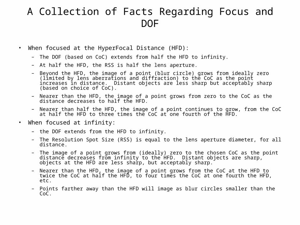
A Collection of Facts Regarding Focus and DOF
• When focused at the HyperFocal Distance (HFD):
– The DOF (based on CoC) extends from half the HFD to infinity.
– At half the HFD, the RSS is half the lens aperture.
– Beyond the HFD, the image of a point (blur circle) grows from ideally zero (limited by lens aberrations and diffraction) to the CoC as the point increases in distance. Distant objects are less sharp but acceptably sharp (based on choice of CoC).
– Nearer than the HFD, the image of a point grows from zero to the CoC as the distance decreases to half the HFD.
– Nearer than half the HFD, the image of a point continues to grow, from the CoC at half the HFD to three times the CoC at one fourth of the HFD.
• When focused at infinity:
– the DOF extends from the HFD to infinity.
– The Resolution Spot Size (RSS) is equal to the lens aperture diameter, for all distance.
– The image of a point grows from (ideally) zero to the chosen CoC as the point distance decreases from infinity to the HFD. Distant objects are sharp, objects at the HFD are less sharp, but acceptably sharp.
– Nearer than the HFD, the image of a point grows from the CoC at the HFD to twice the CoC at half the HFD, to four times the CoC at one fourth the HFD, etc.
– Points farther away than the HFD will image as blur circles smaller than the CoC.
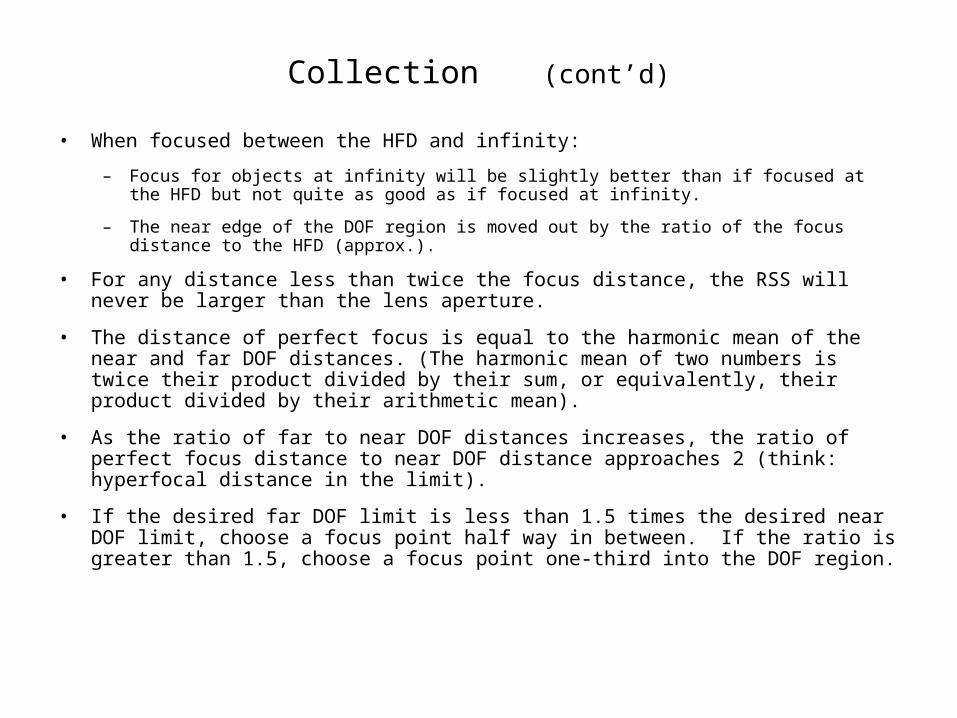
Collection (cont’d)
• When focused between the HFD and infinity:
– Focus for objects at infinity will be slightly better than if focused at the HFD but not quite as good as if focused at infinity.
– The near edge of the DOF region is moved out by the ratio of the focus distance to the HFD (approx.).
• For any distance less than twice the focus distance, the RSS will never be larger than the lens aperture.
• The distance of perfect focus is equal to the harmonic mean of the near and far DOF distances. (The harmonic mean of two numbers is twice their product divided by their sum, or equivalently, their product divided by their arithmetic mean).
• As the ratio of far to near DOF distances increases, the ratio of perfect focus distance to near DOF distance approaches 2 (think: hyperfocal distance in the limit).
• If the desired far DOF limit is less than 1.5 times the desired near DOF limit, choose a focus point half way in between. If the ratio is greater than 1.5, choose a focus point one-third into the DOF region.
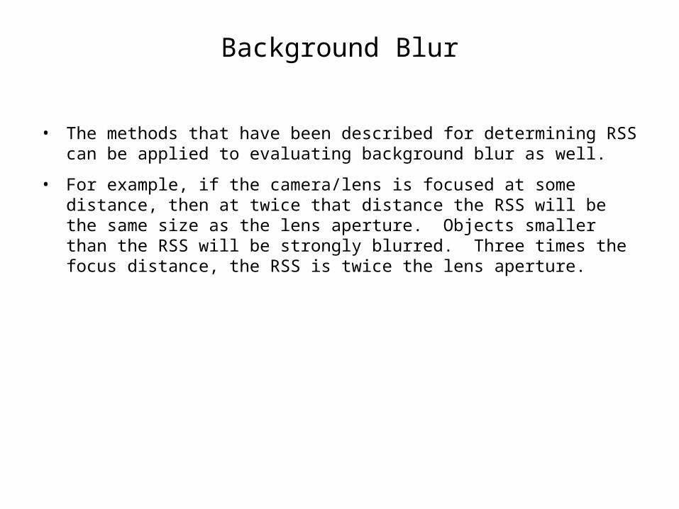
Background Blur
• The methods that have been described for determining RSS can be applied to evaluating background blur as well.
• For example, if the camera/lens is focused at some distance, then at twice that distance the RSS will be the same size as the lens aperture. Objects smaller than the RSS will be strongly blurred. Three times the focus distance, the RSS is twice the lens aperture.

Homework
The best way to really learn this material and how to use it is to grab up your learning tools (camera and lenses) and go take some pictures. Keep notes in your field book. Evaluate the resulting images and record your observations conclusions. Investigate things you do not understand, ask questions.
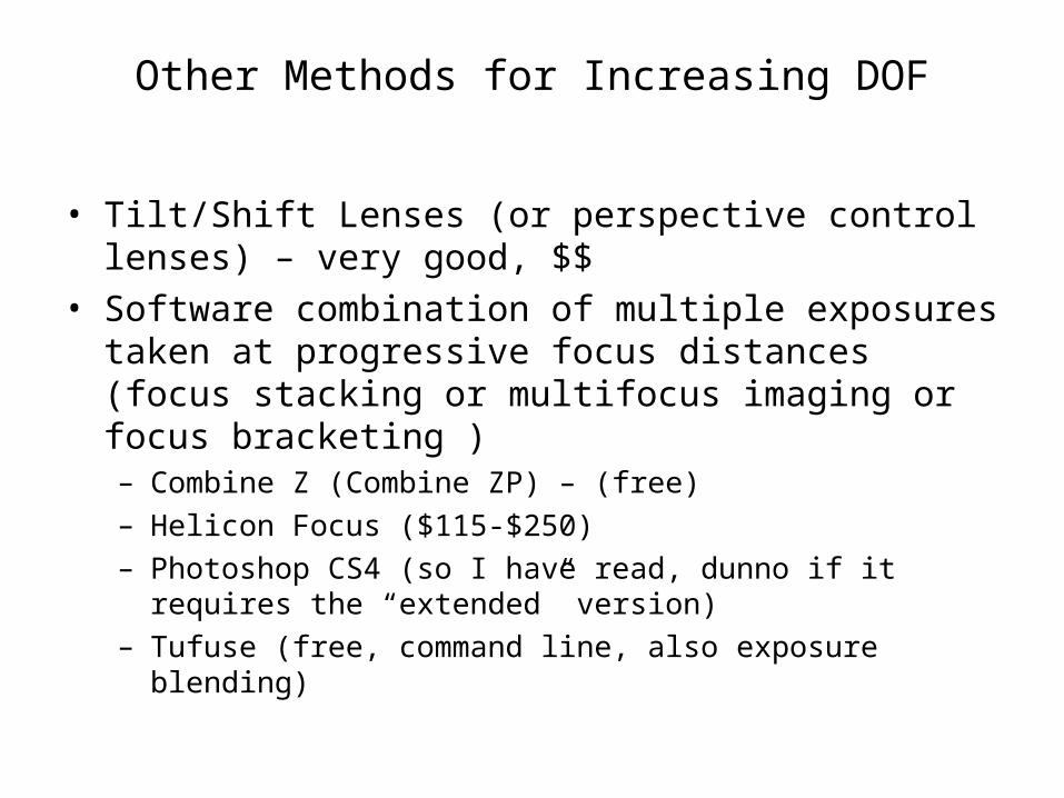
Other Methods for Increasing DOF
• Tilt/Shift Lenses (or perspective control lenses) – very good, $$
• Software combination of multiple exposures taken at progressive focus distances (focus stacking or multifocus imaging or focus bracketing )– Combine Z (Combine ZP) – (free)– Helicon Focus ($115-$250)– Photoshop CS4 (so I have read, dunno if it requires the
“extended” version)– Tufuse (free, command line, also exposure blending)
DOF – Final Comments
• There are a couple of good reasons to avoid small apertures when not absolutely necessary:
– Diffraction
– Sensor dust. Shows up much worse at small apertures.
• Camera DOF Preview button
– Not very useful for judging DOF. Useful for judging how well background is blurred.
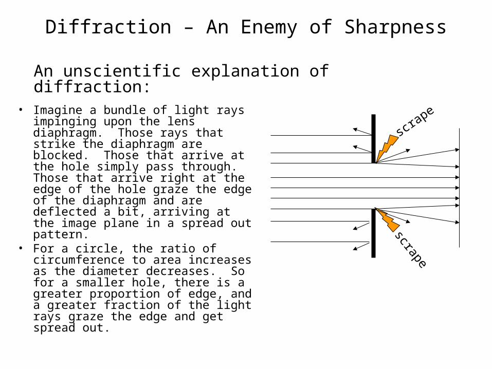
Diffraction – An Enemy of Sharpness
• Imagine a bundle of light rays impinging upon the lens diaphragm. Those rays that strike the diaphragm are blocked. Those that arrive at the hole simply pass through. Those that arrive right at the edge of the hole graze the edge of the diaphragm and are deflected a bit, arriving at the image plane in a spread out pattern.
• For a circle, the ratio of circumference to area increases as the diameter decreases. So for a smaller hole, there is a greater proportion of edge, and a greater fraction of the light rays graze the edge and get spread out.
scrape
scrapeAn unscientific explanation of diffraction:
Diffraction (cont’d)
• At large lens openings (small F-numbers), unsharpness is dominated by lens aberrations. Stopping down the lens reduces most of these.
• At small lens openings (large F-numbers), diffraction dominates. Opening up the lens reduces diffraction.
• Each lens will have a “sweet spot”, or optimum aperture, which best balances these opposing factors.
• For full-frame 35mm, this sweet spot is usually around f/5.6-f/11.
• The Norman Koren site listed in the References has a good discussion of determining the optimum aperture.
• Just as with DOF, diffraction is quantified with respect to a chosen CoC.
• The Bob Atkins DOF calculator referenced previously also computes the diffraction spot size, which you can compare with your chosen CoC (see cautions next slide).
• Another calculator can be found at http://www.cambridgeincolour.com/tutorials/diffraction-photography.htm
• Yet another very interesting one for overall sharpness at http://www.hoen.ca/programming/applications/depthOfField/
Diffraction (cont’d)
• You can find all kinds of numbers for diffraction-limited resolution and diffraction spot size. Various criteria are the Rayleigh Criterion, MTF50, MTF90, Airy Disk FWHM, full Airy disk diameter to first dark ring, etc. Often the writers don’t say which criterion they are using. And some of the stuff is just plain wrong.
• The best way to resolve this is to find out for yourself when diffraction becomes a problem, by experiment.
• However, for object field work, where we choose resolution relative to the objects, we may find it useful to use the formula RSSdiff = d/(1600*D) or RSSdiff = d*N/(1600*f), where RSSdiff is the Resolution Spot Size due to diffraction alone, d is the distance to the object where RSS is being evaluated, D is the lens aperture diameter in millimeters, N is the f-number, and f is the focal length in millimeters. RSS and d are in the same units. In my experience this overstates the visual effect of diffraction by a factor of two or more.
• The camera, including its sensor with its pixel count or pixel density, does not change diffraction. However, with a higher pixel count, you may be able to see finer detail, which will be affected by lower levels of diffraction.
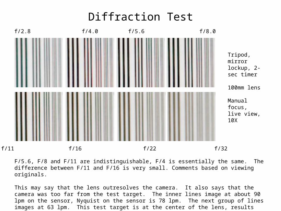
Diffraction Testf/2.8 f/4.0 f/5.6 f/8.0
f/11 f/16 f/22 f/32
Tripod, mirror lockup, 2-sec timer
100mm lens
Manual focus, live view, 10X
F/5.6, F/8 and F/11 are indistinguishable, F/4 is essentially the same. The difference between F/11 and F/16 is very small. Comments based on viewing originals.
This may say that the lens outresolves the camera. It also says that the camera was too far from the test target. The inner lines image at about 90 lpm on the sensor, Nyquist on the sensor is 78 lpm. The next group of lines images at 63 lpm. This test target is at the center of the lens, results will likely be worse off-axis.
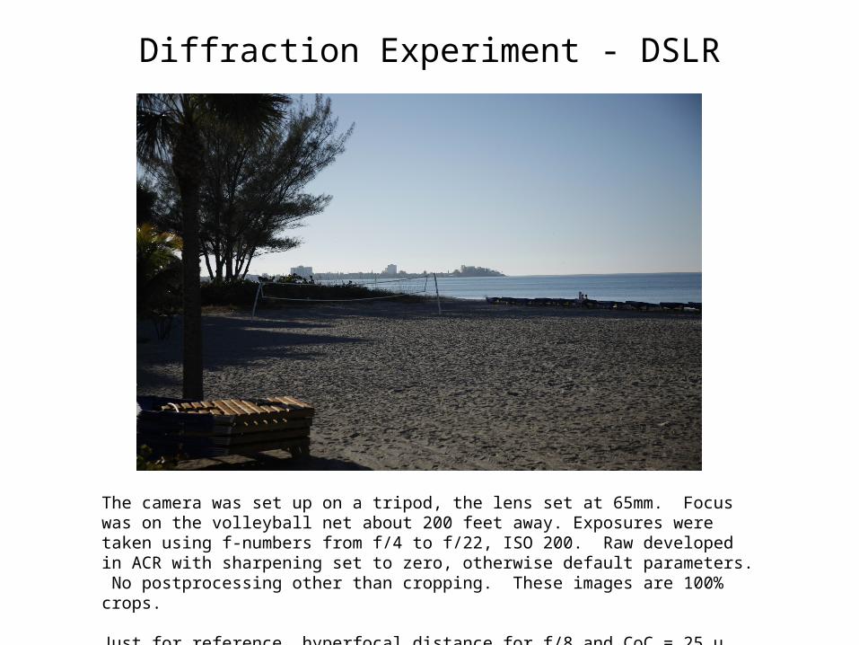
Diffraction Experiment - DSLR
The camera was set up on a tripod, the lens set at 65mm. Focus was on the volleyball net about 200 feet away. Exposures were taken using f-numbers from f/4 to f/22, ISO 200. Raw developed in ACR with sharpening set to zero, otherwise default parameters. No postprocessing other than cropping. These images are 100% crops.
Just for reference, hyperfocal distance for f/8 and CoC = 25 μ was about 70 feet.
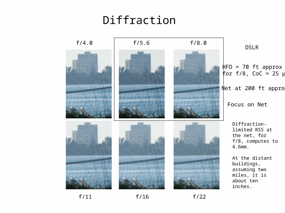
Diffraction
f/4.0 f/5.6 f/8.0
f/11 f/16 f/22
DSLR
HFD = 70 ft approxfor f/8, CoC = 25 μ
Net at 200 ft approx
Focus on Net
Diffraction-limited RSS at the net, for f/8, computes to 4.6mm.
At the distant buildings, assuming two miles, it is about ten inches.
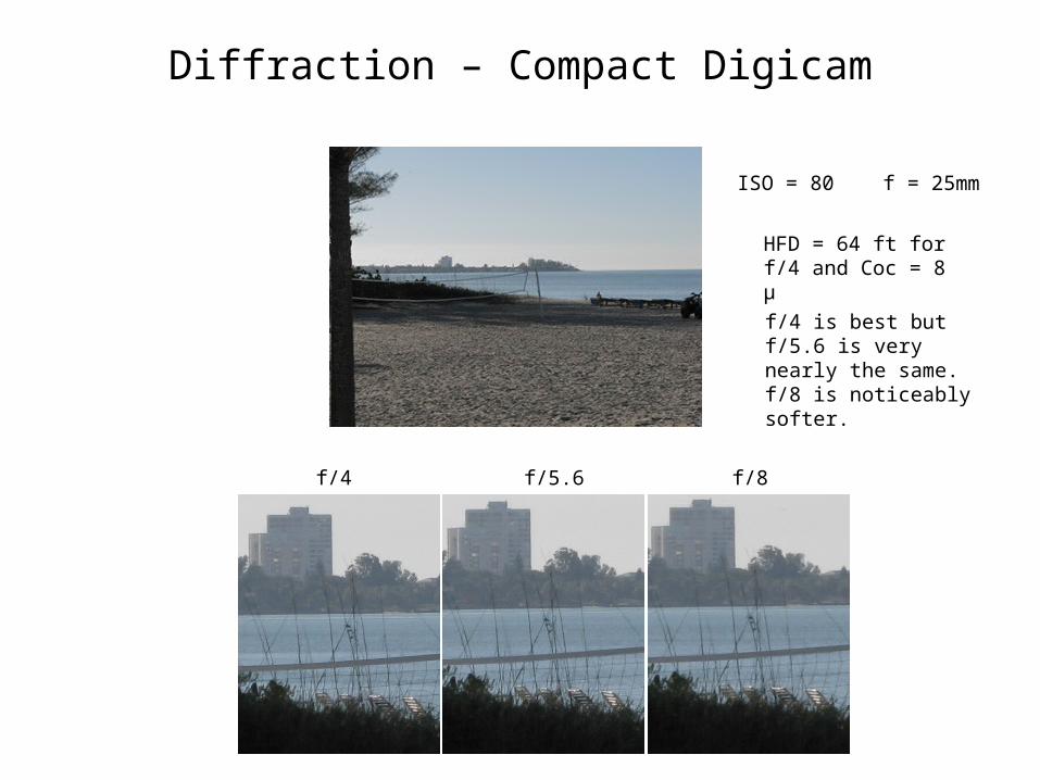
Diffraction – Compact Digicam
ISO = 80 f = 25mm
f/4 f/5.6 f/8
f/4 is best but f/5.6 is very nearly the same. f/8 is noticeably softer.
HFD = 64 ft for f/4 and Coc = 8 μ
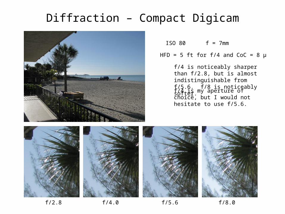
Diffraction – Compact Digicam
f/2.8 f/4.0 f/5.6 f/8.0
ISO 80 f = 7mm
f/4 is noticeably sharper than f/2.8, but is almost indistinguishable from f/5.6. f/8 is noticeably softer.
f/4 is my aperture of choice, but I would not hesitate to use f/5.6.
HFD = 5 ft for f/4 and CoC = 8 μ
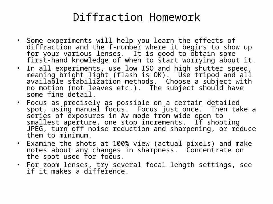
Diffraction Homework
• Some experiments will help you learn the effects of diffraction and the f-number where it begins to show up for your various lenses. It is good to obtain some first-hand knowledge of when to start worrying about it.
• In all experiments, use low ISO and high shutter speed, meaning bright light (flash is OK). Use tripod and all available stabilization methods. Choose a subject with no motion (not leaves etc.). The subject should have some fine detail.
• Focus as precisely as possible on a certain detailed spot, using manual focus. Focus just once. Then take a series of exposures in Av mode from wide open to smallest aperture, one stop increments. If shooting JPEG, turn off noise reduction and sharpening, or reduce them to minimum.
• Examine the shots at 100% view (actual pixels) and make notes about any changes in sharpness. Concentrate on the spot used for focus.
• For zoom lenses, try several focal length settings, see if it makes a difference.
References
• Visual Acuity
– http://www.clarkvision.com/imagedetail/eye-resolution.html (has much higher numbers than commonly used)
– MIL-HDBK-141 http://www.optics.arizona.edu/optomech/references/Mil-hdbk-141.mht
– http://en.wikipedia.org/wiki/Visual_acuity
• Depth of Field and Diffraction
– Carl Zeiss Company, “Camera Lens News #1”, Summer 1997, http://tinyurl.com/b6wt5y
– http://www.largeformatphotography.info/fstop.html
– http://www.mellesgriot.com/pdf/001.20-1.22.pdf
– http://www.clarkvision.com/imagedetail/scandetail.html#diffraction
– http://toothwalker.org/optics/dof.html Some nice color charts
– http://optics.mellesgriot.com/optics_guide_1.asp
– http://www.normankoren.com/Tutorials/MTF6.html
References (cont’d)
• Object Field (Merklinger) Method
– Harold Merklinger’s magazine articles http://www.trenholm.org/hmmerk/HMArtls.html
– This is a PDF copy of Merklinger’s booklet “The INs and OUTs of FOCUS” http://www.trenholm.org/hmmerk/download.html
• Geometrical Optics and Ray Tracing
– http://optics.mellesgriot.com/optics_guide_1.asp
– http://www.lambdares.com/downloads/OSLO_Releases/OSLOOpticsReference.pdf
– MIL-HDBK-141 http://www.optics.arizona.edu/optomech/references/Mil-hdbk-141.mht
– http://en.wikipedia.org/wiki/Category:Geometrical_optics
– http://photo.net/learn/optics/lensTutorial