fonix fa-10 hearing evaluator
TRANSCRIPT
FONIX® FA-10 Hearing Evaluator™
Digital Audiometer
Operator’s Manualversion 1.22
© 2010, Frye Electronics, Inc.All Rights Reserved 6/09
Revised 06/18/10


Note on this Manual
We have organized this manual on the assumption that the user is already trained in how to do hearing tests. However, should that not be the case, or if the operator needs some help, Chapter Six, "Hearing Tests," may be consulted. Section 4.5 describes special tests that can be performed on the FA-10. These are not included as standard functions, but can be added for an additional charge.


Table of Contents
Chapter 1: Introduction . . . . . . . . . . . . . . . . . . . . . . . . . . . . . . . . . . . . . . . . .11.1 Description . . . . . . . . . . . . . . . . . . . . . . . . . . . . . . . . . . . . . . . . . . . . . . . . . . . . . . . .11.2 Audiometer Type. . . . . . . . . . . . . . . . . . . . . . . . . . . . . . . . . . . . . . . . . . . . . . . . . . .11.3 Error Detection . . . . . . . . . . . . . . . . . . . . . . . . . . . . . . . . . . . . . . . . . . . . . . . . . . . .11.4 Service . . . . . . . . . . . . . . . . . . . . . . . . . . . . . . . . . . . . . . . . . . . . . . . . . . . . . . . . . . . .11.5 Safety. . . . . . . . . . . . . . . . . . . . . . . . . . . . . . . . . . . . . . . . . . . . . . . . . . . . . . . . . . . . .21.6 Cleaning the FA-10 . . . . . . . . . . . . . . . . . . . . . . . . . . . . . . . . . . . . . . . . . . . . . . . . .41.7 Standard Accessories . . . . . . . . . . . . . . . . . . . . . . . . . . . . . . . . . . . . . . . . . . . . . . .51.8 Optional Accessories. . . . . . . . . . . . . . . . . . . . . . . . . . . . . . . . . . . . . . . . . . . . . . . .6
Chapter 2: Specifications . . . . . . . . . . . . . . . . . . . . . . . . . . . . . . . . . . . . . . . .9
Chapter 3: Setting Up the Audiometer . . . . . . . . . . . . . . . . . . . . . . . . . .153.1 Rear Panel Connections . . . . . . . . . . . . . . . . . . . . . . . . . . . . . . . . . . . . . . . . . . . .153.2 Rear Panel “See Manual” Symbols . . . . . . . . . . . . . . . . . . . . . . . . . . . . . . . . . .163.3 Audiometer Self Test. . . . . . . . . . . . . . . . . . . . . . . . . . . . . . . . . . . . . . . . . . . . . . .16
Chapter 4: Operation . . . . . . . . . . . . . . . . . . . . . . . . . . . . . . . . . . . . . . . . . .174.1 Input Selections . . . . . . . . . . . . . . . . . . . . . . . . . . . . . . . . . . . . . . . . . . . . . . . . . . .174.2 Output (Both Left and Right Channel) . . . . . . . . . . . . . . . . . . . . . . . . . . . . . . .194.3 Presenting the Signal . . . . . . . . . . . . . . . . . . . . . . . . . . . . . . . . . . . . . . . . . . . . . .20
4.3.1 Hearing Level Selection . . . . . . . . . . . . . . . . . . . . . . . . . . . . . . . . . . . . .204.3.2 Frequency Selection . . . . . . . . . . . . . . . . . . . . . . . . . . . . . . . . . . . . . . . . .204.3.3 Stimulus button . . . . . . . . . . . . . . . . . . . . . . . . . . . . . . . . . . . . . . . . . . . .204.3.4 Reverse button . . . . . . . . . . . . . . . . . . . . . . . . . . . . . . . . . . . . . . . . . . . . .214.3.5 -2.5 dB button . . . . . . . . . . . . . . . . . . . . . . . . . . . . . . . . . . . . . . . . . . . . . .214.3.6 Digital VU Meters . . . . . . . . . . . . . . . . . . . . . . . . . . . . . . . . . . . . . . . . . .21
4.4 Miscellaneous Controls and Indicators . . . . . . . . . . . . . . . . . . . . . . . . . . . . . . .214.4.1 Output Reverse . . . . . . . . . . . . . . . . . . . . . . . . . . . . . . . . . . . . . . . . . . . . .224.4.2 Pulsed . . . . . . . . . . . . . . . . . . . . . . . . . . . . . . . . . . . . . . . . . . . . . . . . . . . .224.4.3 Warble. . . . . . . . . . . . . . . . . . . . . . . . . . . . . . . . . . . . . . . . . . . . . . . . . . . . .224.4.4 Talk Forward . . . . . . . . . . . . . . . . . . . . . . . . . . . . . . . . . . . . . . . . . . . . . . .224.4.5 Mic (Control) . . . . . . . . . . . . . . . . . . . . . . . . . . . . . . . . . . . . . . . . . . . . . . .224.4.6 External (Control) . . . . . . . . . . . . . . . . . . . . . . . . . . . . . . . . . . . . . . . . . .234.4.7 Talk Back (Control) . . . . . . . . . . . . . . . . . . . . . . . . . . . . . . . . . . . . . . . . . .234.4.8 Stereo Monitor (Control) . . . . . . . . . . . . . . . . . . . . . . . . . . . . . . . . . . . . .234.4.9 Patient Response . . . . . . . . . . . . . . . . . . . . . . . . . . . . . . . . . . . . . . . . . . .234.4.10 Power . . . . . . . . . . . . . . . . . . . . . . . . . . . . . . . . . . . . . . . . . . . . . . . . . . . .23
4.5 Special Tests . . . . . . . . . . . . . . . . . . . . . . . . . . . . . . . . . . . . . . . . . . . . . . . . . . . . . .23
4.6 RS232 Option . . . . . . . . . . . . . . . . . . . . . . . . . . . . . . . . . . . . . . . . . . . . . . . . . . . . .284.7 Dual Calibration Option. . . . . . . . . . . . . . . . . . . . . . . . . . . . . . . . . . . . . . . . . . . .294.8 Connecting an iPod to the Audiometer . . . . . . . . . . . . . . . . . . . . . . . . . . . . . . .294.9 Using the FA-10 with a CD player or iPod . . . . . . . . . . . . . . . . . . . . . . . . . . . .31
Chapter 5: Using the FA-10 to Help Select a Hearing Aid . . . . . . . . .375.1 Quick Reference Guide to Using the Hearing Aid Simulator . . . . . . . . . . . .375.2 Complete Instructions for Using the Hearing Aid Simulator. . . . . . . . . . . . .39
5.2.1 Selecting Gain and Frequency Response. . . . . . . . . . . . . . . . . . . . . . . .395.2.2 Selecting Maximum Output (SSPL 90) . . . . . . . . . . . . . . . . . . . . . . . . .42
Chapter 6: Hearing Tests with the Hearing Evaluator . . . . . . . . . . . . .456.1 Preparing to Test . . . . . . . . . . . . . . . . . . . . . . . . . . . . . . . . . . . . . . . . . . . . . . . . . .456.2 The Speech Reception Threshold (SRT) . . . . . . . . . . . . . . . . . . . . . . . . . . . . . . .456.3 Puretone Audiometry . . . . . . . . . . . . . . . . . . . . . . . . . . . . . . . . . . . . . . . . . . . . . .47
6.3.1 Air-Conduction Tests . . . . . . . . . . . . . . . . . . . . . . . . . . . . . . . . . . . . . . . .476.3.2 Bone-Conduction Tests . . . . . . . . . . . . . . . . . . . . . . . . . . . . . . . . . . . . . .48
6.4 Supra-Threshold (above threshold) Tests . . . . . . . . . . . . . . . . . . . . . . . . . . . . .516.4.1 The Most Comfortable Level (MCL) for Speech . . . . . . . . . . . . . . . . .516.4.2 The Uncomfortable Level (UCL) for Speech. . . . . . . . . . . . . . . . . . . . .526.4.3 The Speech Discrimination Score (SDS) . . . . . . . . . . . . . . . . . . . . . . . .52
6.5 Setting the Masking Levels for Thresholds . . . . . . . . . . . . . . . . . . . . . . . . . . . .536.5.1 The Plateau Procedure . . . . . . . . . . . . . . . . . . . . . . . . . . . . . . . . . . . . . . .546.5.2 The One-Level Method . . . . . . . . . . . . . . . . . . . . . . . . . . . . . . . . . . . . . .54
Appendix A: Operational Indicators & Error Messages . . . . . . . . . . . .57
Appendix B: Accessories . . . . . . . . . . . . . . . . . . . . . . . . . . . . . . . . . . . . . . .61
Appendix C: Spondee Words . . . . . . . . . . . . . . . . . . . . . . . . . . . . . . . . . . .65
Appendix D: Phonetically Balanced (PB) Words . . . . . . . . . . . . . . . . . .67
Appendix E: Technical Description of Masking . . . . . . . . . . . . . . . . . .71
Appendix F: Sound Field Calibration Instructions . . . . . . . . . . . . . . . .73
Appendix G: Bone Calibration Tables . . . . . . . . . . . . . . . . . . . . . . . . . . .79
Appendix H: Earphone Calibration Tables . . . . . . . . . . . . . . . . . . . . . . .81
Appendix I: Calibrating the FA-10 . . . . . . . . . . . . . . . . . . . . . . . . . . . . . .83
Frye Electronics FONIX FA-10 Hearing Evaluator 1
Chapter 1: Introduction
1 .1 DescriptionThe FONIX FA-10 Hearing Evaluator is a digital audiometer with a built-in hearing aid simu-lator designed especially for hearing instrument dispensers. The unit includes air, bone, and speech audiometry as standard features. Also included in a standard unit are the Stenger test, and talkover function. A complete monitoring feature is available when the monitor headset or the boom microphone monitor headset is purchased.
The FA-10 is a basic, good quality, light weight, moderately priced audiometer with optional sound field testing and optional accessories, such as a soft carrying case, patient response switch, external speech microphones, monitor headphone, and talkback microphone.
It is a microprocessor-based product with no internal mechanical calibration potentiometers. Calibration is accomplished without opening the instrument case.
Programming options include an RS232 computer interface, Special Test Options, and a Dual Calibration Option. Special tests are: SISI1, MLB2, and ABLB3. (See section 4.5 for special test descriptions.)
1 .2 Audiometer TypeThe FA-10 meets the requirements of Type 3A audiometers. The FA-10 conforms to ANSI S3.6–1996 and IEC 60645-1 1992 standards.
1 .3 Error DetectionThe Hearing Evaluator is designed to test itself and to indicate, to the operator or service person, if an error exists and where it is located. Appendix A is a list of the possible error conditions and the way that the instrument indicates these errors with flashing LEDs on the front panel.
1 .4 ServiceContact Frye Electronics, Inc., P.O. Box 22391, Tigard, Oregon 97281 -3391, U.S.A.
Shipments to 9826 SW Tigard St., Tigard, Oregon 97223.
Telephone: 800/547-8209 in U.S. and Canada; 503/620-2722; Fax 503/639-0128; e-mail: [email protected]. Or contact your local FONIX representative.1SISI – Short Increment Sensitivity Index 2MLB – Monaural Loudness Balance 3ABLB – Alternate Binaural Loudness Balance
2 Chapter 1: Introduction
1 .5 SafetyRear Panel Mains Fuses for 120 VAC use: 0.5A 250V slow 3AG.
Rear Panel Mains Fuses for 220V/240V use: two each 0.16A, 250V, type T.
For the FA-10 to comply with IEC 60601-1, all mains connected electrical equipment attached to the FA-10 must also comply with IEC 60601-1. All computer and audio equipment attached to the FA-10 must be medical grade or else used with a medical grade isolation transformer
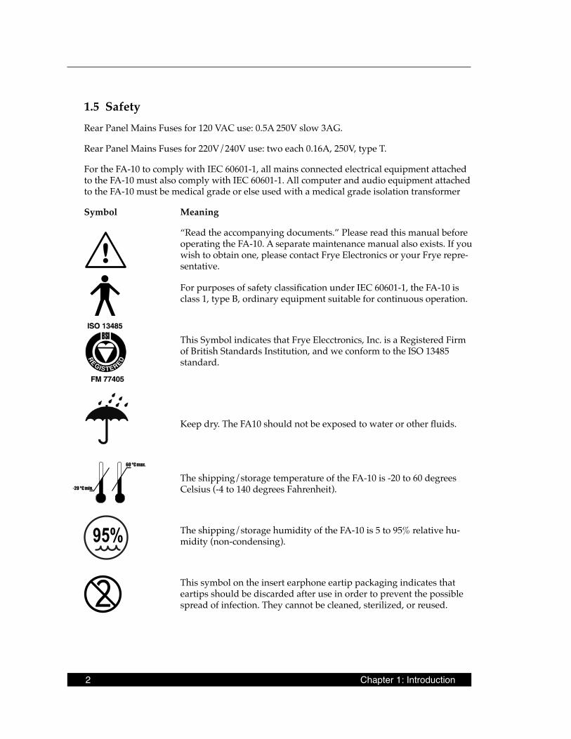
Symbol Meaning
“Read the accompanying documents.” Please read this manual before operating the FA-10. A separate maintenance manual also exists. If you wish to obtain one, please contact Frye Electronics or your Frye repre-sentative.
For purposes of safety classification under IEC 60601-1, the FA-10 is class 1, type B, ordinary equipment suitable for continuous operation.
This Symbol indicates that Frye Elecctronics, Inc. is a Registered Firm of British Standards Institution, and we conform to the ISO 13485 standard.
Keep dry. The FA10 should not be exposed to water or other fluids.
The shipping/storage temperature of the FA-10 is -20 to 60 degrees Celsius (-4 to 140 degrees Fahrenheit).
The shipping/storage humidity of the FA-10 is 5 to 95% relative hu-midity (non-condensing).
This symbol on the insert earphone eartip packaging indicates that eartips should be discarded after use in order to prevent the possible spread of infection. They cannot be cleaned, sterilized, or reused.
95%

Frye Electronics FONIX FA-10 Hearing Evaluator 3
Safety Classification for IEC 60601-1
Type of protection against electric shock: Class I
Degree of protection against electric shock: Type B
Protection against harmful ingress of water: Ordinary
Mode of operation: Continuous
The FA-10 does not require sterilization or disinfection.
Warning: This equipment is not suitable for use in the presence of flammable anaesthetic mixture with air or with oxygen or nitrous oxide.
Connection of peripheral equipment to the FA-10
Compliance with IEC 60601-1-1 Safety requirements for medical electrical systems must be determined on a case-by-case basis.
All electrical equipment attached to the FA-10, such as video monitors, computer equipment, etc. must, at a minimum, meet one of the following conditions:
a. The equipment complies with IEC 60601-1
b. The equipment complies with relevant IEC and ISO safety standards and is supplied from a medical grade isolation transformer.
c. The equipment complies with relevant IEC and ISO safety standards and is kept at least 1.5 meters from the patient.
The allowable leakage currents of IEC 60601-1-1 must not be exceeded. IEC 60601-1-1 should be consulted when assembling such a system.
Electromagnetic compatibility
The FA-10 complies with IEC 60601-1-2.
The FA-10 generates and uses radio frequency energy. In some cases the FA-10 could cause interference to radio or television reception. You can determine if the FA-10 is the source of such interference by turning the unit off and on.
If you are experiencing interference caused by the FA-10, you may be able to correct it by one or more of the following measures:
1. Relocate or reorient the receiving antenna.
2. Increase the distance between the FA-10 and the receiver.
3. Connect the FA-10 to a different outlet than the receiver.

4 Chapter 1: Introduction
In some cases radio transmitting devices, such as cellular telephones, may cause interference to the FA-10. In this case try increasing the distance between the transmitter and the FA-10.
Disposal of the FA-10 and accessories
The FA-10 and some of its accessories contain lead. At the end of its useful life, please recycle or dispose of the FA-10 according to local regulations.
If you are located in the European Union, please report all safety-related concerns to our authorized representative:
Siemens Hearing Instruments Ltd. Alexandra House Newton Road Manor Royal Crawley West Sussex RH109TTENGLAND
Otherwise, please report all safety-related concerns to:
Frye Electronics, IncPO Box 23391Tigard, OR 97281-3391USA
1 .6 Cleaning the FA-10For your safety, disconnect the FA-10 from electrical power while cleaning.
Wipe the FA-10 case with a slightly moist cloth. Use plain water or water with mild dish-washing detergent. Wipe away any detergent with a clean cloth moistened with water, then dry the FA-10. Avoid solvents and abrasives, they can cause permanent damage to the FA-10.
Never allow fluid to enter: • the electronics module • the power switch • the power entry module • the electrical connectors • the keyboard push buttons or rotary controls
Cleaning the earphones:
Although the danger of spreading disease through the audiometric earphones is low, it is not non-existent. The manufacturer of the ear cushions recommends the use of any OSHA (Occu-pation Safety and Health Agency) recommended anti-bacterial soap. Disposable acoustically transparent covers are also available commercially. Insert earphone eartips are single use only can cannot be cleaned.
Frye Electronics FONIX FA-10 Hearing Evaluator 5
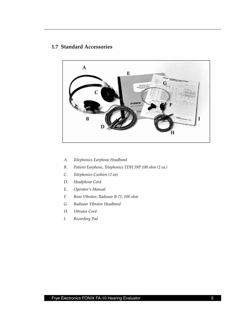
1 .7 Standard Accessories
A. Telephonics Earphone Headband
B. Patient Earphone, Telephonics TDH 39P 100 ohm (2 ea.)
C. Telephonics Cushion (2 ea)
D. Headphone Cord
E. Operator’s Manual
F. Bone Vibrator, Radioear B-71, 100 ohm
G. Radioear Vibrator Headband
H. Vibrator Cord
I. Recording Pad
A
H
I
F
G
E
D
B
C

6 Chapter 1: Introduction
1 .8 Optional Accessories
Gooseneck microphones (2 required) Boom microphone & headset Microphone, economy model
Talkback microphone Microphone stand Microphone stand, telescopic
Dust cover Carrying case Monitor headset
Frye Electronics FONIX FA-10 Hearing Evaluator 7
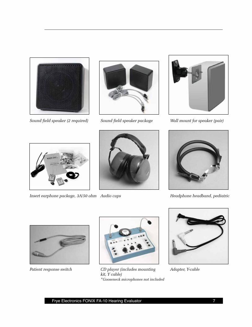
Sound field speaker (2 required) Sound field speaker package Wall mount for speaker (pair)
Insert earphone package, 3A/50 ohm Audio cups Headphone headband, pediatric
Patient response switch CD player (includes mounting Adapter, Y-cable kit, Y cable) *Gooseneck microphones not included

Frye Electronics FONIX FA-10 Hearing Evaluator 9
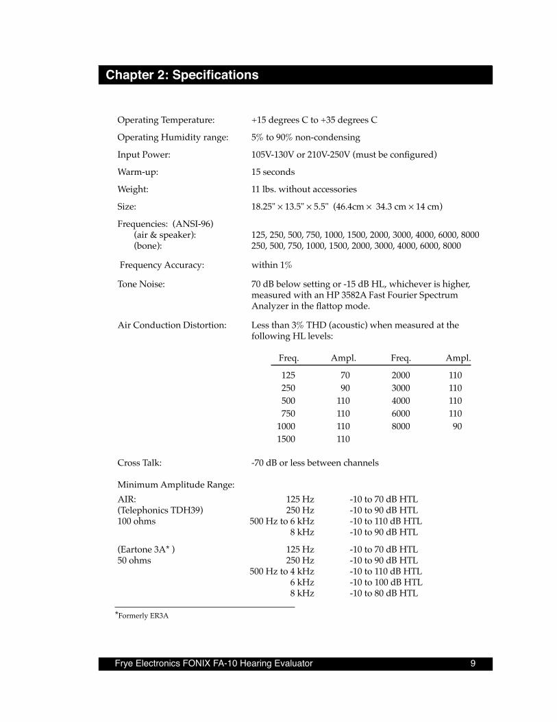
Chapter 2: Specifications
Operating Temperature: +15 degrees C to +35 degrees C
Operating Humidity range: 5% to 90% non-condensing
Input Power: 105V-130V or 210V-250V (must be configured)
Warm-up: 15 seconds
Weight: 11 lbs. without accessories
Size: 18.25" × 13.5" × 5.5" (46.4cm × 34.3 cm × 14 cm)
Frequencies: (ANSI-96) (air & speaker): 125, 250, 500, 750, 1000, 1500, 2000, 3000, 4000, 6000, 8000 (bone): 250, 500, 750, 1000, 1500, 2000, 3000, 4000, 6000, 8000
Frequency Accuracy: within 1%
Tone Noise: 70 dB below setting or -15 dB HL, whichever is higher, measured with an HP 3582A Fast Fourier Spectrum Analyzer in the flattop mode.
Air Conduction Distortion: Less than 3% THD (acoustic) when measured at the following HL levels: Freq. Ampl. Freq. Ampl.
125 70 2000 110 250 90 3000 110 500 110 4000 110 750 110 6000 110 1000 110 8000 90 1500 110
Cross Talk: -70 dB or less between channels
Minimum Amplitude Range: AIR: 125 Hz -10 to 70 dB HTL(Telephonics TDH39) 250 Hz -10 to 90 dB HTL 100 ohms 500 Hz to 6 kHz -10 to 110 dB HTL 8 kHz -10 to 90 dB HTL
(Eartone 3A* ) 125 Hz -10 to 70 dB HTL50 ohms 250 Hz -10 to 90 dB HTL 500 Hz to 4 kHz -10 to 110 dB HTL 6 kHz -10 to 100 dB HTL 8 kHz -10 to 80 dB HTL
*Formerly ER3A

10 Chapter2:Specifications
BONE (ANSI-96): 250 Hz -10 to 40 dB HTL (Radioear B-71) 500 Hz to 750 Hz -10 to 60 dB HTL 100 ohms 1 kHz to 3 kHz -10 to 70 dB HTL 4 kHz -10 to 60 dB HTL 6 kHz -10 to 40 dB HTL 8 kHz -10 to 30 dB HTL White Noise -10 to 50 dB HTL Speech Noise -10 to 50 dB HTL Mic/Ext -10 to 40 dB HTL
SPEAKER (ANSI-96): 125 Hz -10 to 50 dB HTL 8 ohms 250 Hz -10 to 70 dB HTL 500 Hz -10 to 80 dB HTL 1 kHz to 6 kHz -10 to 85 dB HTL 8 kHz -10 to 80 dB HTL
Attenuator Range -10 to110 dB HTL in 5 dB steps. An additional -2.5 dB of and Resolution: resolution is available by pressing the -2.5 dB button.
Attenuator Accuracy: Maximum error at any one attenuator setting is +/- 1.5 dB. Error between any two adjacent settings will be less than .75 dB.
Auxiliary Attenuators: -2.5 dB while “-2.5” button is held down (+/- 1.0 dB).
Warble Tone: 10% frequency deviation (+/- 2%) at a modulation fre-quency of 5 Hz (+/- 1 Hz).
Pulsed Tone: Pulse frequency is 2.25 Hz (+/- 1 Hz). 50% duty cycle (+/- 20%).
Noise Generator: White Noise: flat (+/- 2 dB) to 8 kHz.
Speech Noise: the audiometer provides weighted random noise with a sound pressure spectrum density (energy per Hz) that is constant from 250-1000 Hz. The energy per Hz falls off at a rate of 12 dB/octave from 1000 to 4000 Hz, within +/- 5 dB.
Narrow-band masking noise: upper and lower cut-off fre-quencies at the 3 dB points of the spectral density.
Note: White Noise, Speech Noise, and Narrow Band Noise are all limited to 115 dB in compliance with ANSI specifica-tions.
Frye Electronics FONIX FA-10 Hearing Evaluator 11
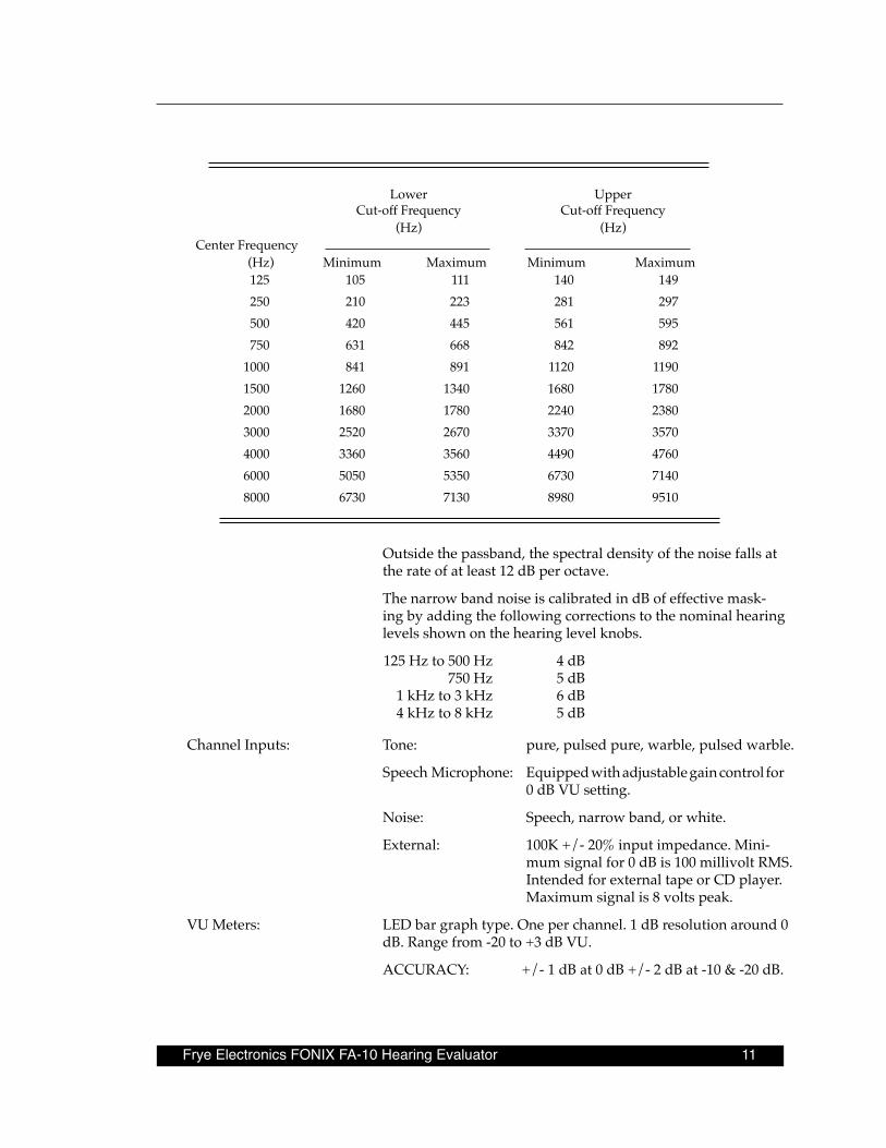
Lower Upper Cut-off Frequency Cut-off Frequency (Hz) (Hz)
Center Frequency (Hz) Minimum Maximum Minimum Maximum
125 105 111 140 149 250 210 223 281 297 500 420 445 561 595 750 631 668 842 892 1000 841 891 1120 1190 1500 1260 1340 1680 1780 2000 1680 1780 2240 23803000 2520 2670 3370 35704000 3360 3560 4490 47606000 5050 5350 6730 71408000 6730 7130 8980 9510
Outside the passband, the spectral density of the noise falls at the rate of at least 12 dB per octave.
The narrow band noise is calibrated in dB of effective mask-ing by adding the following corrections to the nominal hearing levels shown on the hearing level knobs.
125 Hz to 500 Hz 4 dB 750 Hz 5 dB 1 kHz to 3 kHz 6 dB 4 kHz to 8 kHz 5 dB
Channel Inputs: Tone: pure, pulsed pure, warble, pulsed warble.
Speech Microphone: Equipped with adjustable gain control for 0 dB VU setting.
Noise: Speech, narrow band, or white.
External: 100K +/- 20% input impedance. Mini-mum signal for 0 dB is 100 millivolt RMS. Intended for external tape or CD player. Maximum signal is 8 volts peak.
VU Meters: LED bar graph type. One per channel. 1 dB resolution around 0 dB. Range from -20 to +3 dB VU.
ACCURACY: +/- 1 dB at 0 dB +/- 2 dB at -10 & -20 dB.
12 Chapter2:Specifications
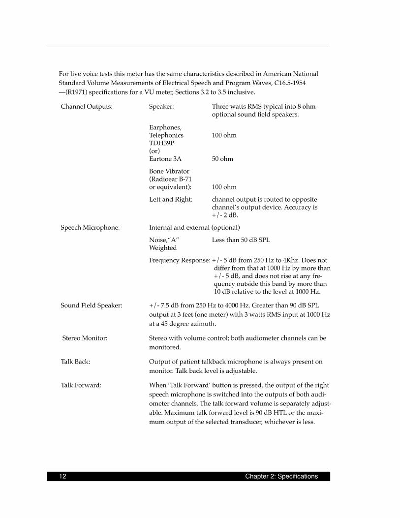
For live voice tests this meter has the same characteristics described in American National Standard Volume Measurements of Electrical Speech and Program Waves, C16.5-1954 —(R1971) specifications for a VU meter, Sections 3.2 to 3.5 inclusive.
Channel Outputs: Speaker: Three watts RMS typical into 8 ohm optional sound field speakers.
Earphones, Telephonics 100 ohm
TDH39P (or) Eartone 3A 50 ohm
Bone Vibrator (Radioear B-71
or equivalent): 100 ohm
Left and Right: channel output is routed to opposite channel’s output device. Accuracy is +/- 2 dB.
Speech Microphone: Internal and external (optional)
Noise,“A” Less than 50 dB SPL Weighted
Frequency Response: +/- 5 dB from 250 Hz to 4Khz. Does not differ from that at 1000 Hz by more than +/- 5 dB, and does not rise at any fre-quency outside this band by more than 10 dB relative to the level at 1000 Hz.
Sound Field Speaker: +/- 7.5 dB from 250 Hz to 4000 Hz. Greater than 90 dB SPL output at 3 feet (one meter) with 3 watts RMS input at 1000 Hz at a 45 degree azimuth.
Stereo Monitor: Stereo with volume control; both audiometer channels can be monitored.
Talk Back: Output of patient talkback microphone is always present on monitor. Talk back level is adjustable.
Talk Forward: When ‘Talk Forward’ button is pressed, the output of the right speech microphone is switched into the outputs of both audi-ometer channels. The talk forward volume is separately adjust-able. Maximum talk forward level is 90 dB HTL or the maxi-mum output of the selected transducer, whichever is less.
Frye Electronics FONIX FA-10 Hearing Evaluator 13
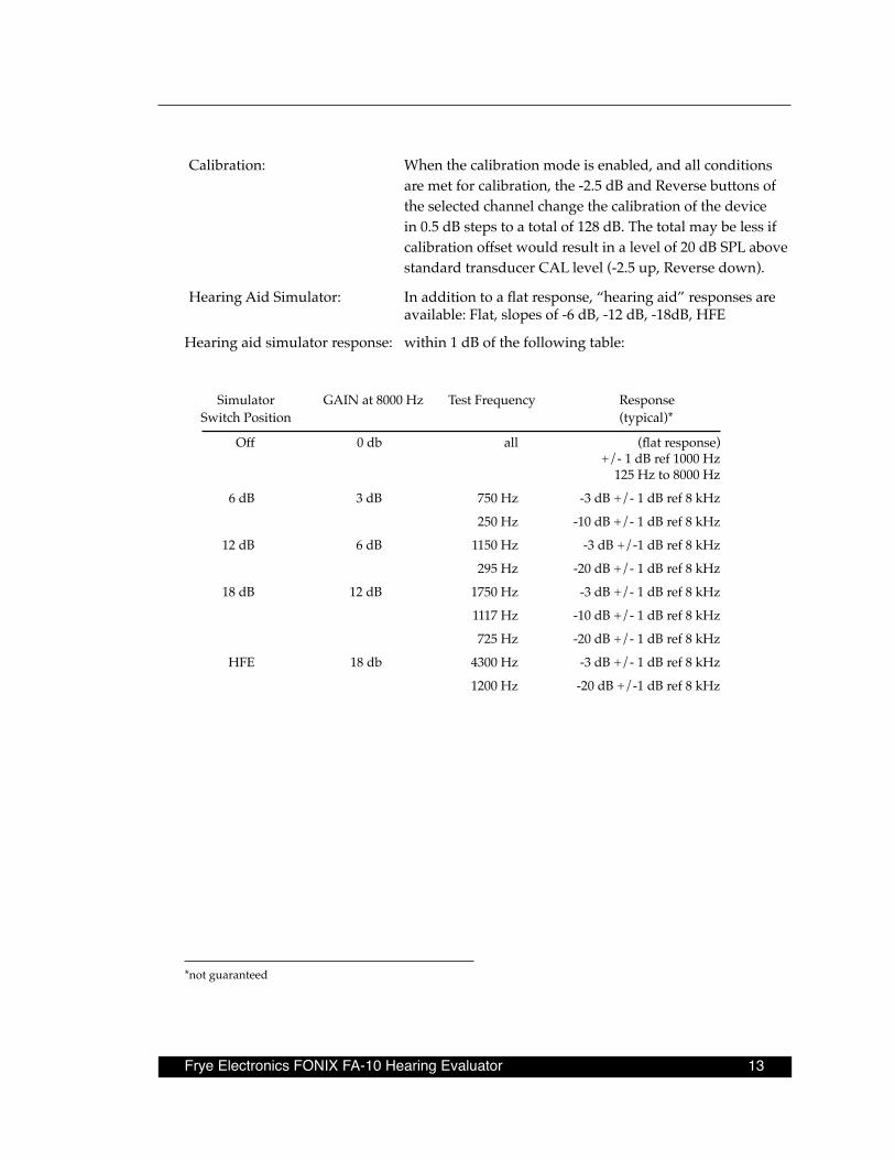
Calibration: When the calibration mode is enabled, and all conditions are met for calibration, the -2.5 dB and Reverse buttons of the selected channel change the calibration of the device in 0.5 dB steps to a total of 128 dB. The total may be less if calibration offset would result in a level of 20 dB SPL above standard transducer CAL level (-2.5 up, Reverse down).
Hearing Aid Simulator: In addition to a flat response, “hearing aid” responses are available: Flat, slopes of -6 dB, -12 dB, -18dB, HFE
Hearing aid simulator response: within 1 dB of the following table:
Simulator GAIN at 8000 Hz Test Frequency Response Switch Position (typical)*
Off 0 db all (flat response) +/- 1 dB ref 1000 Hz 125 Hz to 8000 Hz
6 dB 3 dB 750 Hz -3 dB +/- 1 dB ref 8 kHz
250 Hz -10 dB +/- 1 dB ref 8 kHz
12 dB 6 dB 1150 Hz -3 dB +/-1 dB ref 8 kHz
295 Hz -20 dB +/- 1 dB ref 8 kHz
18 dB 12 dB 1750 Hz -3 dB +/- 1 dB ref 8 kHz
1117 Hz -10 dB +/- 1 dB ref 8 kHz
725 Hz -20 dB +/- 1 dB ref 8 kHz
HFE 18 db 4300 Hz -3 dB +/- 1 dB ref 8 kHz
1200 Hz -20 dB +/-1 dB ref 8 kHz
*not guaranteed

Frye Electronics FONIX FA-10 Hearing Evaluator 15
Chapter 3: Setting Up the Audiometer
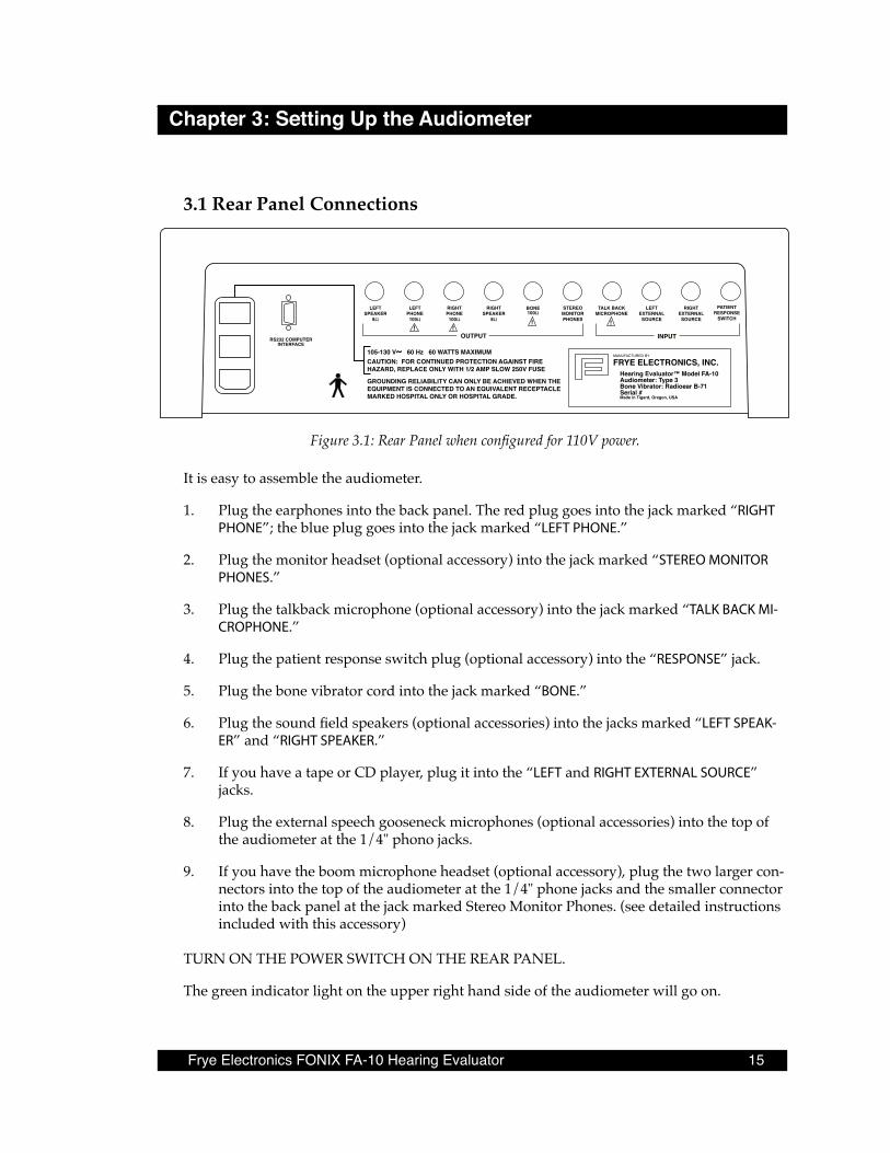
3 .1 Rear Panel Connections
RS232 COMPUTERINTERFACE
MANUFACTURED BY
FRYE ELECTRONICS, INC.Hearing Evaluator™ Model FA-10Audiometer: Type 3Bone Vibrator: Radioear B-71Serial #Made in Tigard, Oregon, USA
CAUTION: FOR CONTINUED PROTECTION AGAINST FIREHAZARD, REPLACE ONLY WITH 1/2 AMP SLOW 250V FUSE
LEFTSPEAKER
8Ω
LEFTPHONE
100Ω
RIGHTPHONE
100Ω
RIGHTSPEAKER
8Ω
BONE100Ω
STEREOMONITORPHONES
TALK BACKMICROPHONE
LEFTEXTERNALSOURCE
RIGHTEXTERNALSOURCE
PATIENTRESPONSE
SWITCH
OUTPUT INPUT
105-130 V~ 60 Hz 60 WATTS MAXIMUM
GROUNDING RELIABILITY CAN ONLY BE ACHIEVED WHEN THEEQUIPMENT IS CONNECTED TO AN EQUIVALENT RECEPTACLEMARKED HOSPITAL ONLY OR HOSPITAL GRADE.
!!!!
Figure 3.1: Rear Panel when configured for 110V power.
It is easy to assemble the audiometer.
1. Plug the earphones into the back panel. The red plug goes into the jack marked “RIGHT PHONE”; the blue plug goes into the jack marked “LEFT PHONE.”
2. Plug the monitor headset (optional accessory) into the jack marked “STEREO MONITOR PHONES.”
3. Plug the talkback microphone (optional accessory) into the jack marked “TALK BACK MI-CROPHONE.”
4. Plug the patient response switch plug (optional accessory) into the “RESPONSE” jack.
5. Plug the bone vibrator cord into the jack marked “BONE.”
6. Plug the sound field speakers (optional accessories) into the jacks marked “LEFT SPEAK-ER” and “RIGHT SPEAKER.”
7. If you have a tape or CD player, plug it into the “LEFT and RIGHT EXTERNAL SOURCE” jacks.
8. Plug the external speech gooseneck microphones (optional accessories) into the top of the audiometer at the 1/4" phono jacks.
9. If you have the boom microphone headset (optional accessory), plug the two larger con-nectors into the top of the audiometer at the 1/4" phone jacks and the smaller connector into the back panel at the jack marked Stereo Monitor Phones. (see detailed instructions included with this accessory)
TURN ON THE POWER SWITCH ON THE REAR PANEL.
The green indicator light on the upper right hand side of the audiometer will go on.

16 Chapter 3: Setting Up the Audiometer
3 .2 Rear Panel “See Manual” Symbols
LEFT RIGHT PHONE PHONE BONE 100 Ω 100 Ω 100 Ω
Figure 3.2 A
The outputs in figure 3.2 A are driven by a current source amplifier. When testing these out-puts, they must be terminated by 100 ohm loads, otherwise erroneous results will occur.
LEFT RIGHT TALK BACK EXTERNAL EXTERNAL MICROPHONE MICROPHONE MICROPHONE
Figure 3.2 B
The microphone inputs in figure 3.2 B are intended for use with the Frye electret condenser microphones, an optional accessory. Power for each microphone is provided over the signal line. If you substitute a non-electret microphone, the output of the microphone may be insuf-ficient. The DC current supplied by the FA-10 rear panel microphone input may interfere with dynamic type microphone operation. Most non-Frye electret microphones with 1/4 inch plugs have an internal 1.5V battery which eventually fails at an inopportune time. We chose to eliminate this battery.
3 .3 Audiometer Self TestAfter turning the audiometer on, there will be a delay of a few seconds while the audiometer tests itself. All LEDs (light emitting diodes) will light up except the response LED. When all LEDs (except Power) go off, the audiometer is ready to use.
Note: Depending on switch positions, some LEDs may remain on or flashing.
If the audiometer finds an error, the LEDs will flash in specific patterns to indicate the prob-lem area. See Appendix A for error messages. The error messages are useful for servicing. Call your Frye representative or Frye Electronics, Inc., toll free at 800-547-8209 in the U.S. and Canada, or 503/620-2722 and report the indicated problem.
Frye Electronics FONIX FA-10 Hearing Evaluator 17
Hearing Level Frequency Hearing Level
Patient Response
Stimulus Stimulus
Input
Output
Hearing AidSimulator
Bone Speaker
LeftChannel
Phone
ToneNarrowBandNoise
WhiteNoise
SpeechNoise
Stenger
LeftExternal
External
Mic
Output
Hearing AidSimulator
12dB18dB
HFEOff
6dB
Bone Speaker
RightChannel
Phone
Tone
Mic ExternalTalkBack
StereoMonitor
TalkForward
External Mic
Power
Output Reverse Pulsed Talk ForwardWarble
Reverse -2.5 dB -2.5 dB Reverse
dB
Hz
dB
FONIX ® HEARING EVALUATORTM
FA-10 Digital Audiometer
CB
A
12dB18dB
HFEOff
6dB
CB
AOption Option
-20-10 -5 -1 +1 +3
-7 -3 0 +2 -20-10 -5 -1 +1 +3
-7 -3 0 +2
InputNarrow
BandNoise
WhiteNoise
SpeechNoise
Stenger
RightExternal
External
Mic
ANSI/ISO HEARING LEVEL
Chapter 4: Operation
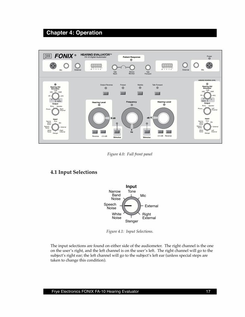
Figure 4.0: Full front panel
4 .1 Input Selections
ToneInput
NarrowBandNoise
WhiteNoise
SpeechNoise
Stenger
RightExternal
External
Mic
Figure 4.1: Input Selections.
The input selections are found on either side of the audiometer. The right channel is the one on the user’s right, and the left channel is on the user’s left. The right channel will go to the subject’s right ear; the left channel will go to the subject’s left ear (unless special steps are taken to change this condition).
18 Chapter 4: Operation
INPUT (Both Left and Right Channels)
Left - blue earphone cable connector Right - red earphone cable connector
The eight-position switches under “Input” on both sides of the Hearing Evaluator front panel are used to select the signal going to the chosen outputs.
INPUT Selections are:
1. Tone - When the marker is on Tone, pure tone is chosen (unless you have also pushed Warble, one of the toggle buttons found above the Frequency knob on the front panel).
Both pure and warble tones may be pulsed. The button marked Pulsed is found next to the Warble button.
Tones may be presented and controlled in each channel independently when both chan-nels are on the Tone input.
2. Narrow Band Noise – The noise band automatically tracks with the frequency chosen in the opposite channel. The user must choose the amplitude of the masking noise. (See appendix E for a description of narrow band noise.) When using noise, Reverse on the chosen channel must be turned on. Important: Never use narrow band noise to mask a speech signal.
3. White Noise – See description in Appendix E and see #2 above.
4. Speech Noise – See description in Appendix E and see #2 above.
5. Mic (Microphone) - The Mic setting is for live voice testing or other uses involving the speech microphone. The microphone may be used to present a live voice signal in ei-ther channel or in each channel simultaneously, and the amplitude of the signal in each channel can be controlled separately. Reverse must be on when using the Mic setting, since otherwise the Tone button would have to be pressed continually for the client to hear speech.
6. External – This input is for an outside source such as a tape or a CD/iPod player plugged into the back panel. Reverse must be on to provide a continuous signal to the client.
7. Right External - Left External - These controls allow the operator to change the input of the external signal from one channel to the other. The right external input is routed to the left output channel and vice-versa.
8. Stenger -This locks the stimulus of the left and right channels together for a test of functional hearing loss. Amplitudes in both channels must be chosen separately by the operator.
Setting the right input to Stenger will cause the input of both channels to be controlled by the left input switch. Setting the left input switch to Stenger will cause the input of both channels to be controlled by the right input switch. Setting both left and right input switches to Stenger will cause the input source to be pure tone in both channels.
Frye Electronics FONIX FA-10 Hearing Evaluator 19
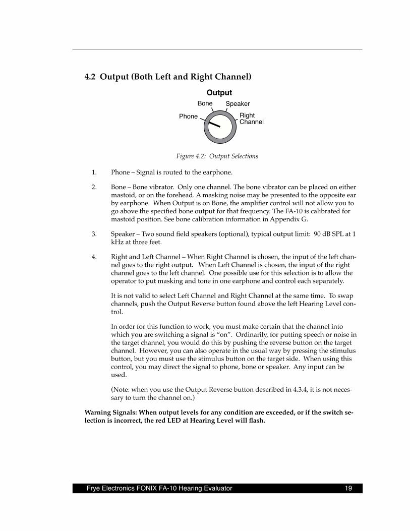
4 .2 Output (Both Left and Right Channel)
OutputBone Speaker
RightChannel
Phone
Figure 4.2: Output Selections
1. Phone – Signal is routed to the earphone.
2. Bone – Bone vibrator. Only one channel. The bone vibrator can be placed on either mastoid, or on the forehead. A masking noise may be presented to the opposite ear by earphone. When Output is on Bone, the amplifier control will not allow you to go above the specified bone output for that frequency. The FA-10 is calibrated for mastoid position. See bone calibration information in Appendix G.
3. Speaker – Two sound field speakers (optional), typical output limit: 90 dB SPL at 1 kHz at three feet.
4. Right and Left Channel – When Right Channel is chosen, the input of the left chan-nel goes to the right output. When Left Channel is chosen, the input of the right channel goes to the left channel. One possible use for this selection is to allow the operator to put masking and tone in one earphone and control each separately.
It is not valid to select Left Channel and Right Channel at the same time. To swap channels, push the Output Reverse button found above the left Hearing Level con-trol.
In order for this function to work, you must make certain that the channel into which you are switching a signal is “on”. Ordinarily, for putting speech or noise in the target channel, you would do this by pushing the reverse button on the target channel. However, you can also operate in the usual way by pressing the stimulus button, but you must use the stimulus button on the target side. When using this control, you may direct the signal to phone, bone or speaker. Any input can be used.
(Note: when you use the Output Reverse button described in 4.3.4, it is not neces-sary to turn the channel on.)
Warning Signals: When output levels for any condition are exceeded, or if the switch se-lection is incorrect, the red LED at Hearing Level will flash.

20 Chapter 4: Operation
4 .3 Presenting the Signal
Hearing Level Frequency Hearing Level
Stimulus StimulusReverse -2.5dB -2.5dB Reverse
dB
Hz
dB
125250
500
7501K 1.5K 2K
3K4K
6K8K
65 4045505560
35
30252015
10
05
-10-5
75808590
95 100 105 110
70
-10 -5
05
1015202530
3540
45505560657075
80859095100
105
110
Figure 4.3: Controls for the Test Signal
4 .3 .1 Hearing Level Selection There are two amplitude or hearing level controls. The one on the operator’s right is ordinar-ily used to test the right ear, and the one on the operator’s left to test the left ear. The Hearing Level numbers are on the “skirt” of the knob, and the correct level is selected by turning the knob until the desired level is at the dB arrow. The white background at the arrow makes it easy to know when the correct position has been reached. Changes are made in 5 dB steps, except with use of the -2.5 dB button. If you attempt to exceed the limitations of the audiom-eter for the type of input, such as bone or speech, the light under Hearing Level will flash to warn you that the level is not valid.
4 .3 .2 Frequency SelectionOne frequency knob is used for both channels. The available frequencies are on the “skirt” of the knob. The selected frequency is the one right above the arrow marked Hz. The white background at the arrow makes it easy to see the selected frequency.
4 .3 .3 Stimulus button Push the button marked Stimulus to present the tone in the chosen channel. The light above the stimulus button will go on as you press the button. If you have turned the Reverse but-ton on, pushing a stimulus button will interrupt the tone.*
*If the -2.5 button is pressed, pushing the stimulus button will not interrupt the tone.

Frye Electronics FONIX FA-10 Hearing Evaluator 21
4 .3 .4 Reverse buttonPush this button for a continuous signal. This button must be turned on when presenting speech, either live voice or tape, and for presenting a masking noise. It may also be used to present a continuous tone.
4 .3 .5 -2 .5 dB buttonPressing the –2.5 dB button will present the signal at 2.5 dB HL below the indicated Hear-ing Level. Once the -2.5 dB button has been pushed, the signal will be presented continually (even if the Reverse button is toggled on) until the button is pushed again. The green stimu-lus button flashes when the 2.5 dB button is activated.
You may use the –2.5 dB button to get the needed 2.5 dB HL increments for speech testing.
4 .3 .6 Digital VU Meters The VU indicators on the Hearing Evaluator consist of red, yellow and green LEDs (light emitting diodes). When a tone is presented, one yellow LED at the 0 level should light up. Speech levels can be monitored by watching the VU meter.
-20-10 -5 -1 +1 +3
-7 -3 0 +2
Figure 4.3.6: Digital VU Meter
4 .4 Miscellaneous Controls and IndicatorsOutput Reverse Pulsed Talk ForwardWarble
Figure 4.4 A: Miscellaneous Controls and Indicators (Buttons located above the Hearing Level and Frequency knobs.)

22 Chapter 4: Operation
4 .4 .1 Output ReverseThis button allows you to swap channels. The input of the right channel goes to the left chan-nel output. The input of the left channel goes to the right channel output. The LED above the button will indicate when this function is on.
4 .4 .2 Pulsed When this button is pushed, the test tone is pulsed on and off at a rate of approximately 2.25 pulses per second. The LED above the button will indicate when pulsed has been chosen.
4 .4 .3 WarbleThis button varies the tone generator frequency output plus and minus 5 percent (10% peak to peak) at a 5 Hz rate. The LED above the button will indicate when warble has been cho-sen.
4 .4 .4 Talk ForwardThis button disables the selected sources and routes the right microphone signal to the se-lected outputs in both channels. The client signal level is adjusted by the talk forward knob found above and a little to the left of the Talk Forward button. The LED above the button indicates when Talk Forward is on. Talk Forward is active only when the button is pushed.
Talk forward is useful in giving instructions to the client in both ears.
Patient Response
TalkBack
StereoMonitor
TalkForward
External Mic
Power
-20-10 -5 -1 +1 +3
-7 -3 0 +2
Figure 4.4 B
4 .4 .5 Mic (Control)These knobs, found next to the built-in microphones on the top right and left sides of the audiometer, allow the operator to set the level of amplification needed to present his or her voice as near as possible to the 0 dB level shown on the VU meter when using either the built-in or external microphones. This control is needed to make sure that live voice testing is properly calibrated. When the input control is on Mic, the VU meter will reflect the signal received at the microphone.
Frye Electronics FONIX FA-10 Hearing Evaluator 23
4 .4 .6 External (Control) This knob controls the level of the signal from external sources, such as tape or CD/iPod player. Turn the knob until the VU meter registers as close to 0 dB as possible so the signal will be properly calibrated.
4 .4 .7 Talk Back (Control)This knob controls the level of the signal reaching the optional monitor headset from the (op-tional) talkback microphone. It allows the operator to hear the client regardless of whether the client has a soft or loud voice. The client's voice is centered between the optional stereo monitor headset earphones.
4 .4 .8 Stereo Monitor (Control)This knob allows the operator to monitor all signals presented to the client and to hear the patient's voice through Talk Back. This control adjusts the level in the operator's ears. Excep-tion: the stereo monitor does not register these two setups: Left channel output selector set to right channel, or Right channel output selector set to left channel.
4 .4 .9 Patient Response This LED lights up when the patient pushes the button on the patient response switch (op-tional). A tone and click are heard in the optional stereo monitor headset.
4 .4 .10 PowerThis signal lights up when the Power switch on the back panel is pushed ON.
4 .5 Special TestsThe following instructions describe how to use Option A, ABLB; Option B, MLB; and Option C, SISI. These options are not standard on the FA-10 Hearing Evaluator.
This manual is not intended as an audiological textbook. If you have not been instructed in the proper use and interpretation of ABLB, MLB, and SISI tests, do not use these specialized tests.
If you have purchased an FA-10 standard model (without these options), the right channel Hearing Aid Simulator Option A, B and C switch positions will function the same as the Off switch position.
To activate these tests: •Set the left channel Hearing Aid Simulator switch to Off. (Dual calibration units can be
set to either primary or secondary calibration.) •Set the right channel Hearing Aid Simulator switch to the desired test.
Option A = ABLB Option B = MLB Option C = SISI
Follow these steps:
24 Chapter 4: Operation
Option A: ABLB—Alternate Binaural Loudness BalanceThis is a test for binaural recruitment. Recruitment is an abnormally large increase in hearing sensation for a given increase in sound level. Derecruitment is an abnormally small increase in hearing sensation for a given increase in sound level.
This test will automatically alternate a tone of a selectable frequency between the left ear and right ear. The tone is presented for:
appoximately 370 milliseconds in the left ear, approximately 130 milliseconds of silence, approximately 370 milliseconds in the right ear, approximately 130 milliseconds of silence(the pattern repeats).
ABLB Setup:right Hearing Aid Simulator: Option A left Hearing Aid Simulator: Off right Output: Phone left Output: Phone left Input: Stenger right Input: Tone Pulse: On left simulus Reverse: On right Stimulus: Off (does not matter) frequency: (select desired frequency) left Hearing Level: (select desired amplitude) right Hearing Level: (select desired amplitude)
Perform the desired ABLB hearing test.
Notes:
Many other Option A, ABLB setups are possible. You may select different inputs and out-puts.
Option A, ABLB works by disabling the Stimulus for one channel for 370 milliseconds, plus 130 milliseconds of silence (both channels), then disabling the other channel for 370 millisec-onds plus 130 milliseconds of silence (both channels).
Option A, ABLB is active when all four of these conditions are met:
• Left Hearing Aid Simulator switch set to Off • Right Hearing Aid Simulator switch set to Option A ˛ • Pulse is ON • Stimulus is enabled for both channels or stimulus is enabled for one channel if Stenger
is selected.
If Pulse is turned off, the FA-10 will operate as if the right Hearing Aid Simulator switch is set to Off.

Frye Electronics FONIX FA-10 Hearing Evaluator 25
Option B: MLB—Monaural Loudness BalanceMLB is a clinical test for monaural recruitment. In this test, a tone of selectable frequency and amplitude is alternated with a second tone which has a different selectable frequency and amplitude. The tones are presented into one ear.
MLB Setup (left ear):
right Hearing Aid Simulator: Option B left Hearing Aid Simulator: Off right Output: Left Channel left Output: Phone left Input: Stenger right Input: Tone Pulse: On
(select reference frequency) left simulus Reverse: Off Frequency: (select desired reference frequency)
(select test frequency) left stimulus Reverse: ON Frequency: (select desired test frequency)
left Hearing Level: (select reference amplitude) right Hearing Level: (select test amplitude)
Perform the desired left ear MLB hearing test.
MLB Setup (right ear):
right Hearing Aid Simulator: Option B left Hearing Aid Simulator: Off right Output: Phone left Output: Right Channel left Input: Stenger right Input: Tone Pulse: On
(select reference frequency) right simulus Reverse: Off Frequency: (select desired reference frequency)
(select test frequency) right stimulus Reverse: ON Frequency: (select desired test frequency) right Hearing Level: (select reference amplitude) left Hearing Level: (select test amplitude)
Perform the desired right ear MLB hearing test.
26 Chapter 4: Operation
Notes:Many other Option B setups are possible although the other Option B setups may not be de-fined as MLB. You may select different inputs and outputs. It is possible to alternate reference tone in one ear with test tone in the other ear.
If Pulse is turned off, the frequency locking mechanism is still in effect. If you set the left Output to Earphone and the right Output to Earphone, the FA-10 can be used as a dual fre-quency audiometer.
Option B works by disabling the Stimulus for one channel for 370 milliseconds, plus 130 milliseconds of silence (both channels), then disabling the other channel for 370 millisec-onds plus 130 milliseconds of silence (both channels). By assigning both audiometer channel outputs to one ear, MLB can be tested. With all Stimulus switches off, the Frequency control selects the reference frequency. With any Stimulus switch on, the Frequency control selects the test frequency.
Option B is active when all four of these conditions are met:
• Left Hearing Aid Simulator switch set to Off • Right Hearing Aid Simulator switch set to Option B • Pulse is ON • Stimulus is enabled for each channel or stimulus is enabled for one channel if Stenger
is selected.
Masking of the MLB untested ear is not possible with Option B.
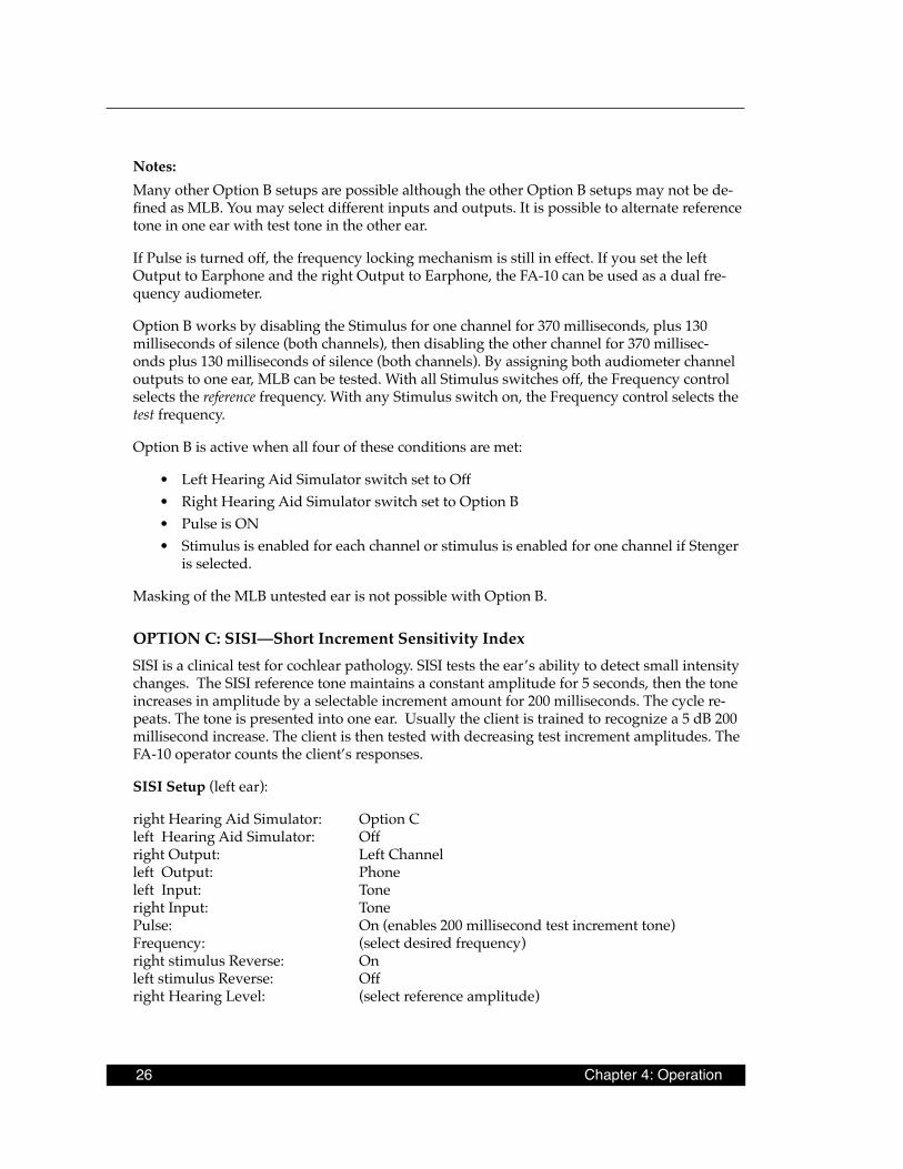
OPTION C: SISI—Short Increment Sensitivity IndexSISI is a clinical test for cochlear pathology. SISI tests the ear’s ability to detect small intensity changes. The SISI reference tone maintains a constant amplitude for 5 seconds, then the tone increases in amplitude by a selectable increment amount for 200 milliseconds. The cycle re-peats. The tone is presented into one ear. Usually the client is trained to recognize a 5 dB 200 millisecond increase. The client is then tested with decreasing test increment amplitudes. The FA-10 operator counts the client’s responses.
SISI Setup (left ear):
right Hearing Aid Simulator: Option C left Hearing Aid Simulator: Off right Output: Left Channel left Output: Phone left Input: Tone right Input: Tone Pulse: On (enables 200 millisecond test increment tone) Frequency: (select desired frequency) right stimulus Reverse: On left stimulus Reverse: Offright Hearing Level: (select reference amplitude)
Frye Electronics FONIX FA-10 Hearing Evaluator 27
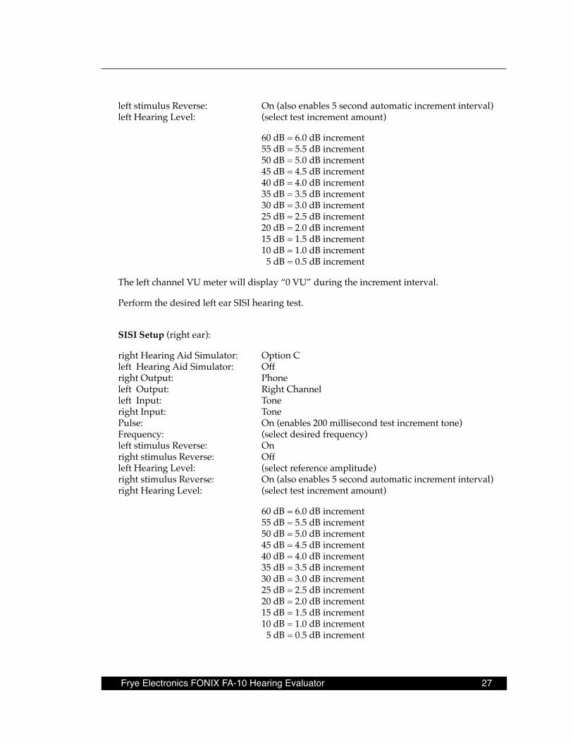
left stimulus Reverse: On (also enables 5 second automatic increment interval)left Hearing Level: (select test increment amount)
60 dB = 6.0 dB increment 55 dB = 5.5 dB increment50 dB = 5.0 dB increment45 dB = 4.5 dB increment40 dB = 4.0 dB increment35 dB = 3.5 dB increment30 dB = 3.0 dB increment25 dB = 2.5 dB increment20 dB = 2.0 dB increment15 dB = 1.5 dB increment10 dB = 1.0 dB increment 5 dB = 0.5 dB increment
The left channel VU meter will display “0 VU” during the increment interval.
Perform the desired left ear SISI hearing test.
SISI Setup (right ear):
right Hearing Aid Simulator: Option C left Hearing Aid Simulator: Off right Output: Phone left Output: Right Channel left Input: Tone right Input: Tone Pulse: On (enables 200 millisecond test increment tone)Frequency: (select desired frequency) left stimulus Reverse: On right stimulus Reverse: Offleft Hearing Level: (select reference amplitude)right stimulus Reverse: On (also enables 5 second automatic increment interval)right Hearing Level: (select test increment amount)
60 dB = 6.0 dB increment 55 dB = 5.5 dB increment 50 dB = 5.0 dB increment 45 dB = 4.5 dB increment 40 dB = 4.0 dB increment 35 dB = 3.5 dB increment 30 dB = 3.0 dB increment 25 dB = 2.5 dB increment 20 dB = 2.0 dB increment 15 dB = 1.5 dB increment 10 dB = 1.0 dB increment 5 dB = 0.5 dB increment

28 Chapter 4: Operation
The right channel VU meter will display “0 VU” during the increment interval.
Perform the desired right ear SISI hearing test.
Notes:To manually cause a SISI increment, turn the increment channel simulus Reverse off. Then press and release increment channel Stimulus button as desired.
The -2.5 dB stimulus switch on the increment channel can be used to decrease the increment by 0.25 dB.
Many other Option C setups are possible, although the other Option C setups may not be defined as SISI. You may select different inputs and outputs.
Option C works (for example, to the left ear) by directing the reference tone from the right channel to the left channel, then producing an additional increment tone in the left channel.
In order for the increment feature to operate, the left and right channels must be added to-gether. For example, if you are testing the left ear, the right output must be set to left channel.
Option C is active when all four of these conditions are met:
• Left Hearing Aid Simulator switch set to Off • Right Hearing Aid Simulator switch set to Option C • Pulse is ON • Stimulus is enabled for each channel or stimulus is enabled for one channel if Stenger
is selected.
Masking of the SISI untested ear is not possible with Option C.
A stereo monitor headset will allow the operator to clearly hear the SISI increment in the increment channel.
4 .6 RS232 OptionThe RS232 option consists of hardware and software to be installed in the FONIX FA-10 and FA-12 Hearing Evaluators. It also includes the USB RS232 cable, and a CD ROM containing the documentation, device drivers, sample programs, and diagnostics which run on the PC.
The RS232 option allows the computer to receive data from the audiometer and to control the audiometer operation.
Information can be retrieved from the audiometer as either ASCII data streams or via the Frye Instrument Packet Protocol. The audiometer can be controlled via the Frye Instrument Packet Protocol only (for reliability reasons).
All control positions on the audiometer front panel can be read at any time through the RS232 interface. A 16-step buffer is provided to prevent lost data should the computer not be able to read the panel before the next change occurs.
Frye Electronics FONIX FA-10 Hearing Evaluator 29
The functionality of the FONIX audiometer is enhanced when it is switched to operate under computer control. The frequency can be set to any value rather than being limited to the frequencies available on the panel switch. The level can be controlled in 0.1dB steps rather than the 2.5dB steps available from the front panel. The FONIX audiometer also becomes a full two channel audiometer when under computer control. The left and right channels are individually controlled, including separate frequency control in each channel. Operation of the audiometer when under computer control is via a virtual control panel accessed via the RS232 interface .
We supply full documentation for the protocol used by the audiometer on the disk. Along with the documentation we supply a device driver which will run on any Windows PC or true compatible computer and an extensive set of sample programs. The sample programs are written in Pascal. The full source code for the programs is provided.
The documentation supplied in the disk is mainly targeted at programmers who will be implementing software to link the audiometer to a computer.
4 .7 Dual Calibration OptionWhen the FA-10 has the Dual Calibration Option, the user has access to a TDH-39 headphone calibration table and an insert earphone calibration table. This allows the user to take accu-rate audiometric measurements with either type of transducer.
The left Hearing Aid Simulator knob is used to switch between the calibrations. The TDH-39 headphone calibration choice is represented by a headset icon. The insert earphone calibra-tion choice is represented by a box enclosing the letters “3A” or “5A,” depending upon the type of inserts ordered with the audiometer.
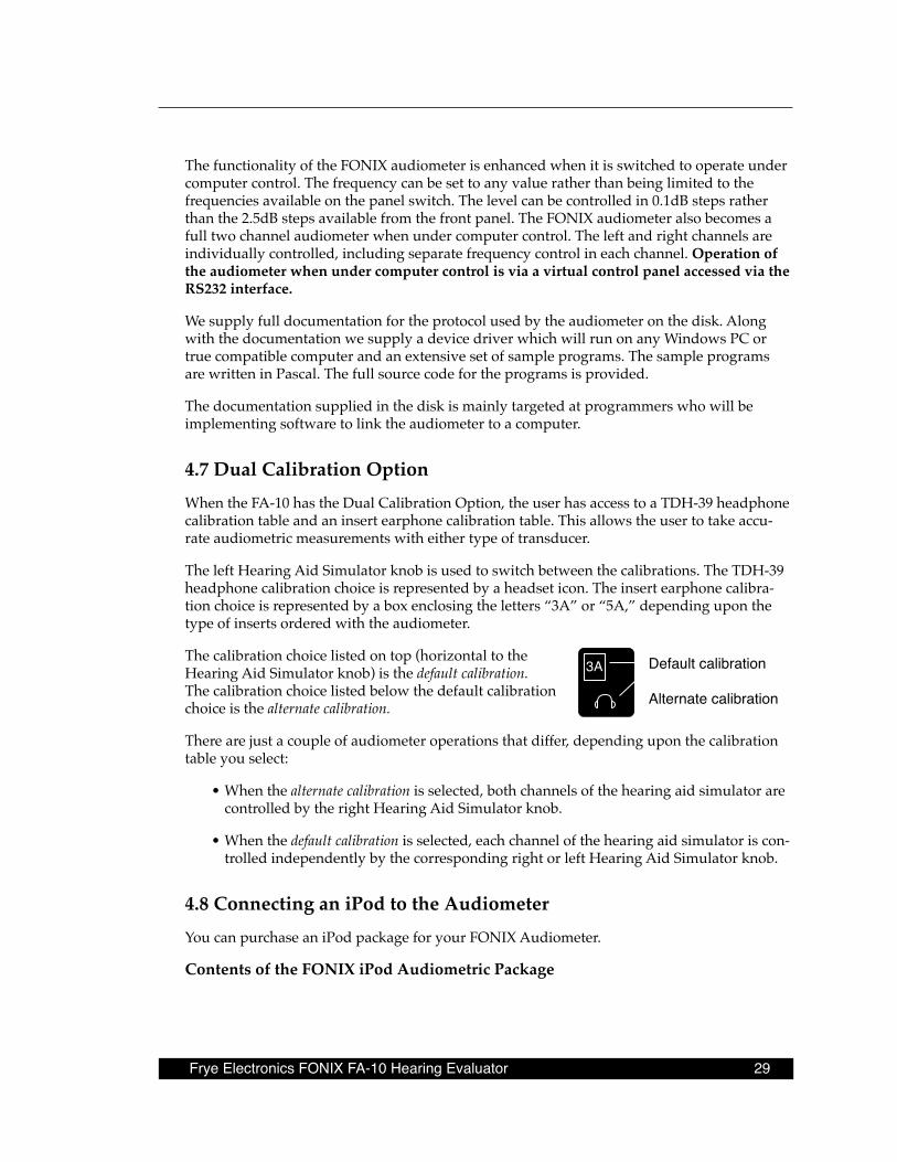
The calibration choice listed on top (horizontal to the Hearing Aid Simulator knob) is the default calibration. The calibration choice listed below the default calibration choice is the alternate calibration.
There are just a couple of audiometer operations that differ, depending upon the calibration table you select:
• When the alternate calibration is selected, both channels of the hearing aid simulator are controlled by the right Hearing Aid Simulator knob.
• When the default calibration is selected, each channel of the hearing aid simulator is con-trolled independently by the corresponding right or left Hearing Aid Simulator knob.
4 .8 Connecting an iPod to the AudiometerYou can purchase an iPod package for your FONIX Audiometer.
Contents of the FONIX iPod Audiometric Package
Default calibration
Alternate calibration

30 Chapter 4: Operation
The FONIX iPod Audiometric package includes:
• iPod nano loaded with the FONIX Audiometric Speech Tests• iPod dock• Dock power supply• USB Cable• Y-Cable
Setup
To set up the iPod for use with the FONIX audiometer:
1. Connect the power supply to the iPod dock. 2. Connect Y-Cable to the iPod dock and the Left External Source and Right External
Source socks on the back of your FONIX audiometer.3. Insert iPod into dock.
RS232 COMPUTERINTERFACE
CAUTION: FOR CONTINUED PROTECTION AGAINST FIREHAZARD, REPLACE ONLY WITH 1/2 AMP SLOW 250V FUSE
LEFTSPEAKER
8Ω
LEFTPHONE
100Ω
RIGHTPHONE
100Ω
RIGHTSPEAKER
8Ω
BONE100Ω
STEREOMONITORPHONES
TALK BACKMICROPHONE
LEFTEXTERNAL
SOURCE
RIGHTEXTERNAL
SOURCE
PATIENTRESPONSE
SWITCH
OUTPUT INPUT
105-130 V~ 60 Hz 60 WATTS MAXIMUM
GROUNDING RELIABILITY CAN ONLY BE ACHIEVED WHEN THEEQUIPMENT IS CONNECTED TO AN EQUIVALENT RECEPTACLEMARKED HOSPITAL ONLY OR HOSPITAL GRADE.
!!!!
Red plug goes to Right External Source
Line out
Y-Adapter Cable,3.5 mm to dual 1/4"
FA-10/12 Back Panel
To Power Supply
Frye Electronics FONIX FA-10 Hearing Evaluator 31
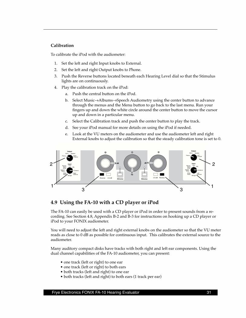
Calibration
To calibrate the iPod with the audiometer:
1. Set the left and right Input knobs to External.2. Set the left and right Output knobs to Phone.3. Push the Reverse buttons located beneath each Hearing Level dial so that the Stimulus
lights are on continuously.4. Play the calibration track on the iPod:
a. Push the central button on the iPod.b. Select Music→Albums→Speech Audiometry using the center button to advance
through the menus and the Menu button to go back to the last menu. Run your fingers up and down the white circle around the center button to move the cursor up and down in a particular menu.
c. Select the Calibration track and push the center button to play the track.d. See your iPod manual for more details on using the iPod if needed.e. Look at the VU meters on the audiometer and use the audiometer left and right
External knobs to adjust the calibration so that the steady calibration tone is set to 0.
Stimulus Stimulus
Input
OutputBone Speaker
LeftChannel
Phone
ToneNarrowBandNoise
WhiteNoise
SpeechNoise
Stenger
LeftExternal
External
Mic
OutputBone Speaker
RightChannel
Phone
Tone
Reverse -2.5 dB -2.5 dB Reverse
dB
Hz
dB
InputNarrow
BandNoise
WhiteNoise
SpeechNoise
Stenger
RightExternal
External
Mic
1
2
31
2
3
4 .9 Using the FA-10 with a CD player or iPodThe FA-10 can easily be used with a CD player or iPod in order to present sounds from a re-cording. See Section 4.8, Appendix B-2 and B-3 for instructions on hooking up a CD player or iPod to your FONIX audiometer.
You will need to adjust the left and right external knobs on the audiometer so that the VU meter reads as close to 0 dB as possible for continuous input. This calibrates the external source to the audiometer.
Many auditory compact disks have tracks with both right and left ear components. Using the dual channel capabilities of the FA-10 audiometer, you can present:
• one track (left or right) to one ear• one track (left or right) to both ears• both tracks (left and right) to one ear• both tracks (left and right) to both ears (1 track per ear)
32 Chapter 4: Operation
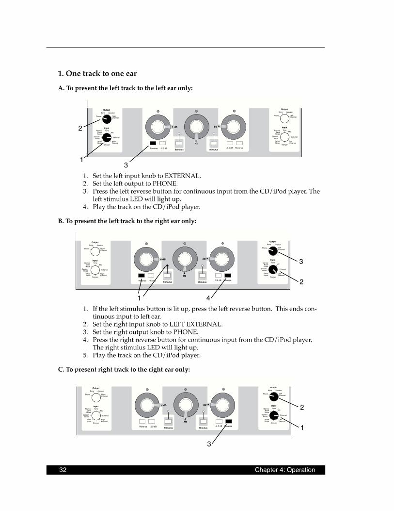
1 . One track to one ear
A . To present the left track to the left ear only:
Stimulus Stimulus
Input
OutputBone Speaker
LeftChannel
Phone
ToneNarrowBandNoise
WhiteNoise
SpeechNoise
Stenger
LeftExternal
External
Mic
OutputBone Speaker
RightChannel
Phone
Tone
Reverse -2.5 dB -2.5 dB Reverse
dB
Hz
dB
InputNarrow
BandNoise
WhiteNoise
SpeechNoise
Stenger
RightExternal
External
Mic
1
2
31. Set the left input knob to EXTERNAL.2. Set the left output to PHONE.3. Press the left reverse button for continuous input from the CD/iPod player. The
left stimulus LED will light up.4. Play the track on the CD/iPod player.
B . To present the left track to the right ear only:
Stimulus Stimulus
Input
OutputBone Speaker
LeftChannel
Phone
ToneNarrowBandNoise
WhiteNoise
SpeechNoise
Stenger
LeftExternal
External
Mic
OutputBone Speaker
RightChannel
Phone
Tone
Reverse -2.5 dB -2.5 dB Reverse
dB
Hz
dB
InputNarrow
BandNoise
WhiteNoise
SpeechNoise
Stenger
RightExternal
External
Mic
1
2
3
41. If the left stimulus button is lit up, press the left reverse button. This ends con-
tinuous input to left ear.2. Set the right input knob to LEFT EXTERNAL.3. Set the right output knob to PHONE.4. Press the right reverse button for continuous input from the CD/iPod player.
The right stimulus LED will light up.5. Play the track on the CD/iPod player.
C . To present right track to the right ear only:
Stimulus Stimulus
Input
OutputBone Speaker
LeftChannel
Phone
ToneNarrowBandNoise
WhiteNoise
SpeechNoise
Stenger
LeftExternal
External
Mic
OutputBone Speaker
RightChannel
Phone
Tone
Reverse -2.5 dB -2.5 dB Reverse
dB
Hz
dB
InputNarrow
BandNoise
WhiteNoise
SpeechNoise
Stenger
RightExternal
External
Mic
1
2
3
Frye Electronics FONIX FA-10 Hearing Evaluator 33
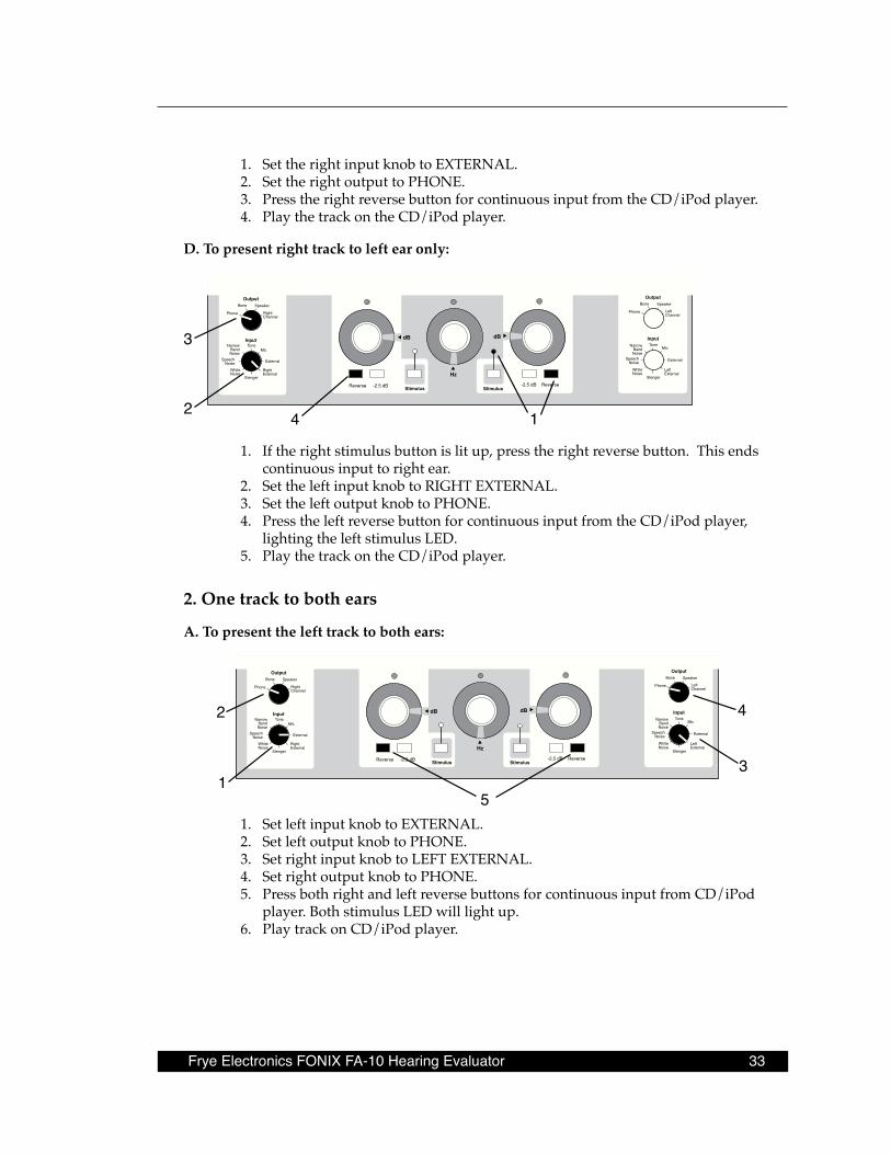
1. Set the right input knob to EXTERNAL.2. Set the right output to PHONE.3. Press the right reverse button for continuous input from the CD/iPod player.4. Play the track on the CD/iPod player.
D . To present right track to left ear only:
Stimulus Stimulus
Input
OutputBone Speaker
LeftChannel
Phone
ToneNarrowBandNoise
WhiteNoise
SpeechNoise
Stenger
LeftExternal
External
Mic
OutputBone Speaker
RightChannel
Phone
Tone
Reverse -2.5 dB -2.5 dB Reverse
dB
Hz
dB
InputNarrow
BandNoise
WhiteNoise
SpeechNoise
Stenger
RightExternal
External
Mic
2
3
14
1. If the right stimulus button is lit up, press the right reverse button. This ends continuous input to right ear.
2. Set the left input knob to RIGHT EXTERNAL.3. Set the left output knob to PHONE.4. Press the left reverse button for continuous input from the CD/iPod player,
lighting the left stimulus LED.5. Play the track on the CD/iPod player.
2 . One track to both ears
A . To present the left track to both ears:
Stimulus Stimulus
Input
OutputBone Speaker
LeftChannel
Phone
ToneNarrowBandNoise
WhiteNoise
SpeechNoise
Stenger
LeftExternal
External
Mic
OutputBone Speaker
RightChannel
Phone
Tone
Reverse -2.5 dB -2.5 dB Reverse
dB
Hz
dB
InputNarrow
BandNoise
WhiteNoise
SpeechNoise
Stenger
RightExternal
External
Mic
4
1
2
3
51. Set left input knob to EXTERNAL.2. Set left output knob to PHONE.3. Set right input knob to LEFT EXTERNAL.4. Set right output knob to PHONE.5. Press both right and left reverse buttons for continuous input from CD/iPod
player. Both stimulus LED will light up.6. Play track on CD/iPod player.
34 Chapter 4: Operation
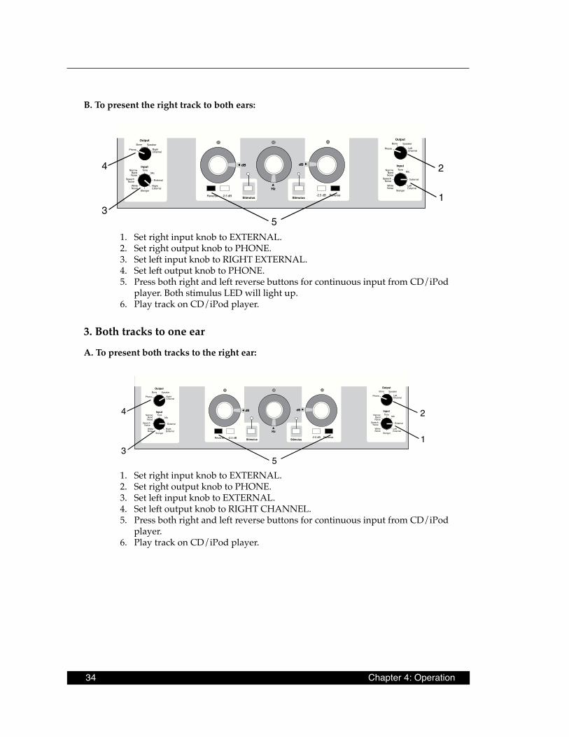
B . To present the right track to both ears:
Stimulus Stimulus
Input
OutputBone Speaker
LeftChannel
Phone
ToneNarrowBandNoise
WhiteNoise
SpeechNoise
Stenger
LeftExternal
External
Mic
OutputBone Speaker
RightChannel
Phone
Tone
Reverse -2.5 dB -2.5 dB Reverse
dB
Hz
dB
InputNarrow
BandNoise
WhiteNoise
SpeechNoise
Stenger
RightExternal
External
Mic
3
4
5
1
2
1. Set right input knob to EXTERNAL.2. Set right output knob to PHONE.3. Set left input knob to RIGHT EXTERNAL.4. Set left output knob to PHONE.5. Press both right and left reverse buttons for continuous input from CD/iPod
player. Both stimulus LED will light up.6. Play track on CD/iPod player.
3 . Both tracks to one ear
A . To present both tracks to the right ear:
Stimulus Stimulus
Input
OutputBone Speaker
LeftChannel
Phone
ToneNarrowBandNoise
WhiteNoise
SpeechNoise
Stenger
LeftExternal
External
Mic
OutputBone Speaker
RightChannel
Phone
Tone
Reverse -2.5 dB -2.5 dB Reverse
dB
Hz
dB
InputNarrow
BandNoise
WhiteNoise
SpeechNoise
Stenger
RightExternal
External
Mic
3
4
5
1
2
1. Set right input knob to EXTERNAL.2. Set right output knob to PHONE.3. Set left input knob to EXTERNAL.4. Set left output knob to RIGHT CHANNEL.5. Press both right and left reverse buttons for continuous input from CD/iPod
player.6. Play track on CD/iPod player.

Frye Electronics FONIX FA-10 Hearing Evaluator 35
B . To present both tracks to the left ear:
Stimulus Stimulus
Input
OutputBone Speaker
LeftChannel
Phone
ToneNarrowBandNoise
WhiteNoise
SpeechNoise
Stenger
LeftExternal
External
Mic
OutputBone Speaker
RightChannel
Phone
Tone
Reverse -2.5 dB -2.5 dB Reverse
dB
Hz
dB
InputNarrow
BandNoise
WhiteNoise
SpeechNoise
Stenger
RightExternal
External
Mic
3
4
5
1
2
1. Set right input knob to EXTERNAL.2. Set right output knob to LEFT CHANNEL.3. Set left input knob to EXTERNAL.4. Set left output knob to PHONE.5. Press both right and left reverse buttons for continuous input from CD/iPod
player.6. Play track from CD/iPod player.
4 . Both tracks to both ears
This will play the left track in the left ear and the right track in the right ear:
Stimulus Stimulus
Input
OutputBone Speaker
LeftChannel
Phone
ToneNarrowBandNoise
WhiteNoise
SpeechNoise
Stenger
LeftExternal
External
Mic
OutputBone Speaker
RightChannel
Phone
Tone
Reverse -2.5 dB -2.5 dB Reverse
dB
Hz
dB
InputNarrow
BandNoise
WhiteNoise
SpeechNoise
Stenger
RightExternal
External
Mic
3
4
5
1
2
1. Set right input knob to EXTERNAL.2. Set right output knob to PHONE.3. Set left input knob to EXTERNAL.4. Set left output knob to PHONE.5. Press both right and left reverse buttons for continuous input from CD/iPod
player.6. Play track from CD/iPod player.
To play the left track in the right ear and the right track in the left ear, use the setup above and press the Output Reverse button.

Frye Electronics FONIX FA-10 Hearing Evaluator 37
Chapter 5: Using the FA-10 to Help Select a Hearing Aid
The Hearing Aid Simulator of the FA-10 consists of five frequency-response slopes, ranging from flat (“Off”) to extreme high-frequency-emphasis (“HFE”). The slopes were chosen to simulate the choices normally available in hearing aid specifications. The Hearing Aid Simu-lator gives the dispenser and the listener an initial idea of the acoustic effects of a hearing aid, but the Simulator is not a real hearing aid. A real hearing aid is likely to sound different. Live (“Mic”) or recorded (“External”) inputs can be used with the Hearing Aid Simulator. A “Quick Reference Guide” to operation is given below. Complete instructions follow.
Note: If your instrument has the Dual Calibration Option, use only the right Hearing Aid Simulator dial when testing with the second calibration.
5 .1 Quick Reference Guide to Using the Hearing Aid Simulator
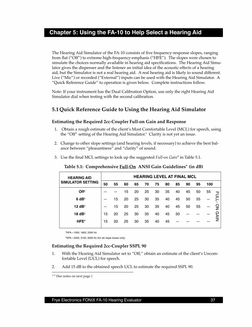
Estimating the Required 2cc-Coupler Full-on Gain and Response1. Obtain a rough estimate of the client’s Most Comfortable Level (MCL) for speech, using
the “Off” setting of the Hearing Aid Simulator.† Clarity is not yet an issue.
2. Change to other slope settings (and hearing levels, if necessary) to achieve the best bal-ance between “pleasantness” and “clarity” of sound.
3. Use the final MCL settings to look up the suggested Full-on Gain* in Table 5.1.
Table 5 .1: Comprehensive Full-On ANSI Gain Guidelines* (in dB)
HEARING LEVEL AT FINAL MCL 50 55 60 65 70 75 80 85 90 95 100
Off‡ — — 15 20 25 30 35 40 45 50 55
6 dB‡ — 15 20 25 30 35 40 45 50 55 —
12 dB‡ — 15 20 25 30 35 40 45 50 55 —
18 dB‡ 15 20 25 30 35 40 45 50 — — —
HFE# 15 20 25 30 35 40 45 — — — —
‡HFA—1000, 1600, 2500 Hz#SPA—2000, 3150, 5000 Hz (for ski slope losses only)
Estimating the Required 2cc-Coupler SSPL 901. With the Hearing Aid Simulator set to “Off,” obtain an estimate of the client’s Uncom-
fortable Level (UCL) for speech.
2. Add 15 dB to the obtained speech UCL to estimate the required SSPL 90.
†/* (See notes on next page )
HEARING AIDSIMULATOR SETTING
FULL- O
N G
AIN
38 Chapter 5: Using the FA-10 to Help Select a Hearing Aid
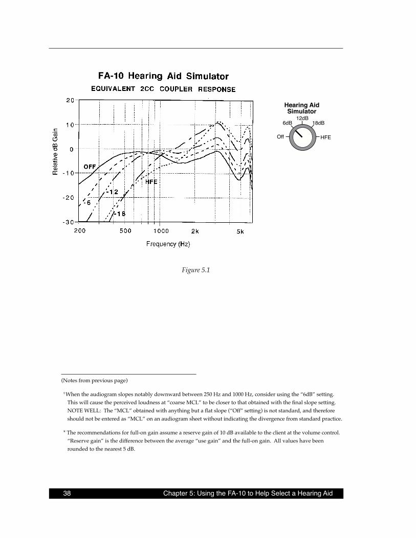
Figure 5.1
(Notes from previous page)
† When the audiogram slopes notably downward between 250 Hz and 1000 Hz, consider using the “ 6dB” setting. This will cause the perceived loudness at “coarse MCL” to be closer to that obtained with the final slope setting. NOTE WELL: The “MCL” obtained with anything but a flat slope (“Off” setting) is not standard, and therefore should not be entered as “MCL” on an audiogram sheet without indicating the divergence from standard practice.
* The recommendations for full-on gain assume a reserve gain of 10 dB available to the client at the volume control. “Reserve gain” is the difference between the average “use gain” and the full-on gain. All values have been rounded to the nearest 5 dB.
Hearing AidSimulator
12dB18dB
HFEOff
6dB
Frye Electronics FONIX FA-10 Hearing Evaluator 39
5 .2 Complete Instructions for Using the Hearing Aid SimulatorThere are many methods for fitting hearing aids. The choice of method is up to the indi-vidual fitter. The instructions below are merely suggestions on how to use the Hearing Aid Simulator; they are given as a guide to selecting gain, frequency response, and maximum output. The suggested procedures can give the operator a starting point toward a final hear-ing aid selection.
5 .2 .1 Selecting Gain and Frequency Response
Coarse MCL EstimateThe first step is to make a coarse estimate of the client’s Most Comfortable Level (MCL) for speech.
• Set the channel Input for “Mic” if you are going to use Monitored Live Voice, or “Ex-ternal” if you are going to use recorded materials.
• Set the channel Output for “Phone.”
• Adjust the Mic or External level control so that speech will be presented at 0 VU.
• Use the “Off” setting of the Hearing Aid Simulator.*
• While presenting speech materials or monitored live voice (as close as possible to 0 VU), raise and lower the “Hearing Level” dial until the client indicates that the speech is at a comfortable hearing level, not too loud, not too soft. There may be a range of levels that satisfy this requirement. Choose the lowest level that is comfort-able for the client to listen to without straining.
Choosing a Slope and Final MCL(Note: For “ski-slope” losses, use the separate procedure, below.)
Once you have established a “coarse MCL” setting, try changing the Hearing Aid Simulator setting to other slopes, while asking the client to judge the sound quality and intelligibility. The goal here is to find the setting with the best balance between “clarity” and “pleasantness.” If the client indicates that one slope setting sounds louder or softer than another, adjust the Hearing Level dial to achieve MCL at each setting you try.
Make a note of the final hearing level and slope settings.
* When the audiogram slopes notably downward between 250 Hz and 1000 Hz, consider using the “ 6dB” setting. This will cause the perceived loudness at “coarse MCL” to be closer to that obtained with the final slope setting. NOTE WELL: The “MCL” obtained with anything but a flat slope (“Off” setting) is not standard, and therefore should not be entered as “MCL” on an audiogram sheet without indicating the divergence from standard practice.
40 Chapter 5: Using the FA-10 to Help Select a Hearing Aid
Selecting Full-on GainTables 5.1 (p.33) and 5.2 (below) are guidelines for fitting monaurally to ears having average canal dimensions and normal middle-ear status. When fitting binaurally, slightly less gain may be required for MCL. Also, ITE and Canal instruments may require slightly less high-frequency gain.
Equivalent 2cc coupler gain curves for each slope setting of the Hearing Aid Simulator are shown in Figure 5.1. These coupler curves assume a behind-the-ear hearing aid with a sealed earmold. The gain for each slope has been adjusted in the Hearing Aid Simulator so that the overall level of “audiometer speech noise” in a 6cc coupler is the same for each setting. This approximates equal loudness for each setting, in the normal ear.
Because of this built-in adjustment for equal loudness, the correction factors between “HL-at-MCL” and “2cc-coupler full-on gain”, shown in Table 5.2, differ according to which slope set-ting is used. Simply subtract the appropriate number in Table 5.2 from the “Hearing Level” dial setting to get the suggested full-on gain* (or look up the suggested full-on gain in Table 5.1).
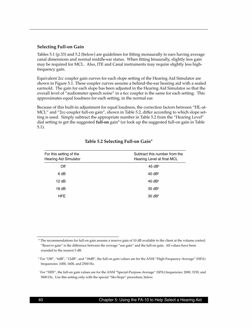
Table 5 .2 Selecting Full-on Gain*
For this setting of the Subtract this number from the HearingAidSimulator HearingLevelatfinalMCL
Off 45 dB‡
6 dB 40 dB‡
12 dB 40 dB‡
18 dB 35 dB‡
HFE 35 dB#
* The recommendations for full-on gain assume a reserve gain of 10 dB available to the client at the volume control. “Reserve gain” is the difference between the average “use gain” and the full-on gain. All values have been rounded to the nearest 5 dB.
‡ For “Off”, “6dB”, “12dB”, and “18dB”, the full-on gain values are for the ANSI “High-Frequency-Average” (HFA) frequencies: 1000, 1600, and 2500 Hz.
# For “HFE”, the full-on gain values are for the ANSI “Special-Purpose-Average” (SPA) frequencies: 2000, 3150, and 5000 Hz. Use this setting only with the special “Ski-Slope” procedure, below.
Frye Electronics FONIX FA-10 Hearing Evaluator 41
Large Vent Simulation for Ski-slope LossesFor “ski-slope” hearing losses, you will likely be using a very large vent, where low frequen-cies are allowed to pass unamplified into the ear canal, while only the high frequencies are amplified. The flexible design of the FA-10 lets you simulate a large-vent fitting in the fol-lowing way:
1. You will use one audiometer channel to feed unamplified sound (50 dB HL) to the test ear and the other audiometer channel to amplify only the high frequencies. You must use a single sound source, fed through both audiometer channels, to the same ear. Ex-ternal sources (e.g., tape or CD) can be used for this purpose with all FA-10s. To use live voice, you must have either the optional gooseneck microphones or the optional boom microphone/headset. Do not use the built-in panel mics for this purpose. The possible setups are:
• A single external input (tape/CD) channel. For example, to feed the left tape or CD channel to the left ear, use the following settings:
Left Input to “External”Left Output to “Phone”Right Input to “Left External”Right Output to “Left Channel”
• The gooseneck microphones. The two microphones must be placed directly side-by-side or head-to-head, with the sound inlets as close as possible to each other, even touching. (Hint: Remove the foam wind screens first, but be sure to place the micro-phones lower than mouth level, to avoid amplifying breath noises.) Use the follow-ing settings:
Both Inputs to “Mic.”Output of the test-ear side to “Phone.”Output of the non-test-ear side to the opposite channel.
• The boom microphone/headset. Use the following settings:
Both Inputs to “Mic.”Output of the test-ear side to “Phone.”Output of the non-test-ear side to the opposite channel.
2. On the non-test-ear side, set the Hearing Aid Simulator to “Off” and set the Hearing Level to 50 dB HL. This passes the low and mid frequencies to the test ear, unamplified.
3. On the test-ear side, set the Hearing Aid Simulator to “HFE.”
4. Set the Hearing Level dial of the test-ear side to 30 dB HL.
5. While presenting speech materials through both channels, gradually raise the Hear-ing Level of the test-ear-side only, until maximum clarity is achieved. This adjustment changes the level of the high frequencies, while maintaining a constant SPL for the lower frequencies, as Figure 5.2.1 on the next page illustrates.

42 Chapter 5: Using the FA-10 to Help Select a Hearing Aid
Hearing AidSimulator
12dB18dB
HFEOff
6dB
Figure 5.2.1
NOTE: The maximum HL with this setup is lower than it is when the two channels are not combined in this special manner. Do not use the “6dB”, “12dB”, or “18dB” settings with this setup . Use only the “HFE” setting .
5 .2 .2 Selecting Maximum Output (SSPL 90)Selecting the SSPL 90 involves an estimate of the threshold of discomfort. The idea is to be sure the hearing aid never crosses that threshold, and thus, will never be uncomfortable. Some dispensers like to measure the Uncomfortable Level (UCL) or Loudness Discomfort Level (LDL), and some like to measure the Highest Comfortable Level (HCL). The main difference between these measures is in the instructions given the client.* It is the operator’s choice as to which method to use.
* For UCL or LDL, the client may be asked to indicate the level at which the sound is “too loud,” or the level at which the client would not like to be exposed for any length of time. For HCL, the client may be asked to indicate the level at which one would not like to have the sound any louder—but one could tolerate that level for a minute or two. For obvious reasons, the HCL usually is lower than the UCL or LDL. Often, a repeated measurement yields a higher level.
Frye Electronics FONIX FA-10 Hearing Evaluator 43
For either method, the Hearing Aid Simulator should be set to the “Off” position. Using live or recorded speech materials, start at MCL and gradually increase the hearing level until the client indicates that the desired level is reached. In addition to asking the client to tell you when the sound has reached the desired level, keep a careful eye on the client, watching for involuntary signs of discomfort. The moment you have any indication of discomfort, turn the hearing level down and discontinue presentation, making note of the level that caused the discomfort. You never want the hearing aid to reach this level.
For speech tests of comfort/discomfort, the measured UCL, LDL, or HCL can roughly be converted to 2cc-coupler SPL by adding 15 dB to the HL level you do not want the hearing aid to exceed. Choose a hearing aid whose SSPL 90 does not exceed the resulting SPL value.
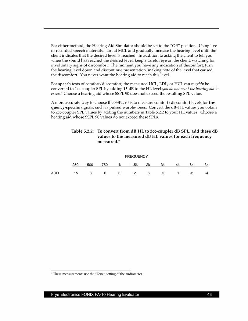
A more accurate way to choose the SSPL 90 is to measure comfort/discomfort levels for fre-quency-specific signals, such as pulsed warble-tones. Convert the dB–HL values you obtain to 2cc-coupler SPL values by adding the numbers in Table 5.2.2 to your HL values. Choose a hearing aid whose SSPL 90 values do not exceed these SPLs.
Table 5 .2 .2: To convert from dB HL to 2cc-coupler dB SPL, add these dB values to the measured dB HL values for each frequency measured .*
FREQUENCY
250 500 750 1k 1.5k 2k 3k 4k 6k 8k
ADD 15 8 6 3 2 6 5 1 -2 -4
* These measurements use the “Tone” setting of the audiometer

Frye Electronics FONIX FA-10 Hearing Evaluator 45
Chapter 6: Hearing Tests with the Hearing Evaluator
6 .1 Preparing to TestBecause of the serious nature of hearing tests, the tester should always be highly confident of the accuracy of the test equipment. At the beginning of each day it is a good idea to do a "biological calibration" check. That is, the tester checks his or her own hearing thresholds to be sure the expected results are obtained. If there is a discrepancy, the calibration of the audiometer should be checked thoroughly. In addition to daily "biological calibration," espe-cially if the audiometer has been in use for a long time, it is a good idea to periodically check the correct performance of all rotary switches. Do this by listening to the patients’ earphones while manipulating the switches and presenting signals.
All hearing tests must be done with the patient in a quiet room, to prevent background noise from interfering with the tests. Seat the patient in a position where you can easily watch their response, but do not let them watch you during the tests.
Before you start the tests, remove anything the patient has in their ears (hearing aids, cotton, etc.) Also, it is a good idea to look into the patient’s ears with an otoscope to be sure the ear canals are open. Be sure you have adequate training before you use an otoscope.
Give the patient instructions before you start the hearing tests. For threshold tests, ask the patient to respond either by saying “yes,” by raising a hand, or by pushing on a response button. Regardless of the response you choose, be sure you give instructions to the patient before you place the earphones over their ears.
Place the earphones over the ears carefully. If the patient is wearing any ear jewelry, you might ask them to remove it, or ask them if the earphones are causing them discomfort. Cen-ter the earphones directly over the ear canals. Put the right earphone with the red connector on the right ear and the left earphone with the blue connector on the left ear.
The pressure of the earphones causes some ear canals to collapse (close). When you place the earphones, check to be sure the ear canals do not collapse. If it appears the pressure of the earphones is closing the ear canal, remove the earphone from the headset and have an as-sistant hold the earphone securely on the ear while lightly pulling the ear backwards to keep the canal open.
It is a good idea to test the better ear first. If the difference between ears is significant, testing the better ear first helps you learn whether or not masking will be needed when you test the poorer ear. If you can, find out which ear is likely to be the better one by asking the patient.
6 .2 The Speech Reception Threshold (SRT)Audiometer Settings
Input: Mic (for live voice) or External (for recorded voice)
Output: Phone
46 Chapter 6: Hearing Tests with the Hearing Evaluator
Hearing Level: 70 dB (initial setting)
Hearing Aid Simulator: Off
Reverse (near “-2.5 dB” button): On
Adjust the Mic or External trim controls (on upper panel near VU meters) so that when you present the words, the VU meter indicates the “0” level.
It is a good idea to start the hearing tests by finding the patient’s hearing sensitivity level for speech. This test is called the Speech Reception Threshold, or SRT. The SRT can be tested with live or recorded speech materials. A live-voice SRT can be given only if the tester and the patient are placed in separate rooms. The acoustical separation between the patient and the tester must be good enough so the patient is not able to hear the tester’s voice, except through the audiometer. If you are using live voice, be sure also that the patient cannot see the tester’s lips. Otherwise the test will be invalid.
Instead of using live voice, the SRT can be given with pre-recorded word lists. The recorded-word procedure assures a consistent, clear presentation, but provides less personal interac-tion between the tester and the patient. Recorded words are presented at fixed intervals, and some patients have difficulty listening to and repeating the recorded words fast enough. The tester can help the patient through support and encouragment. For example, tell the patient that it is all right to skip some words. Also, tell the patient to guess at the words.
The SRT evaluation might proceed as follows:
Test the better hearing ear first.
1. Give the patient about ten, two-syllable words at 70 dB HL. These words are called Spondaic words. (See Appendix C.) If the patient cannot hear the words at 70 dB HL, increase the hearing level until a comfortable listening level is achieved. Then present the words. These initial ten words are given to familiarize the patient with the words and the manner of the test. Tell the patient to repeat each word.
2. After the patient is familiar with the test procedure, tell the patient, “I am going to make the words softer. Keep repeating the words as long as you can. If you are not sure about a word, just guess.”
3. Between each presented word, reduce the hearing level in 10-dB steps, until the patient can no longer repeat the words.
4. At that point, increase the hearing level in 5-dB steps until the patient responds cor-rectly.
5. Repeat the sequence (decreasing and increasing the hearing level) until you can judge the point where patient can repeat the words about half the time.
The Speech Reception Threshold, SRT, is defined as the point at which the patient can repeat the words correctly fifty percent of the time. Before concluding this test, you should cross the threshold several times. Some patients get discouraged; you should reassure them, telling them they are doing fine.
Frye Electronics FONIX FA-10 Hearing Evaluator 47
6. Next, repeat the test in the opposite ear. It is not necessary to present the ten initial words a second time, because the patient is now familiar with the task.
Masking with the SRT test
When one ear has better hearing than the other ear, you must use masking noise in the non-test ear (better ear) under certain conditions. First, test the SRT of the better ear. Then, when testing the SRT of the poorer ear, use masking in the non-test ear (better ear) if either of the two following conditions occurs: 1] When the difference in the SRT between ears is 45 dB or more; or 2] When the difference between the SRT of the test ear and the puretone-average* air- or bone-conduction threshold of the non-test ear is 45 dB or more. With the SRT test, use “Speech Noise” for masking the non-test ear. See Section 6.5 for further instructions on setting masking levels.
6 .3 Puretone Audiometry
6 .3 .1 Air-Conduction TestsAudiometer Settings
Input: Tone
Output: Phone
Frequency: Initial setting: 1000 Hz
Hearing Level: Initial setting: best: SRT + 20 dB; otherwise: 60 dB
Pulsed and/or Warble: Optional
If possible, begin testing with the better hearing ear. Instruct the patient to respond to the air-conduction puretone test signals by saying “yes,” by raising a hand, or by pushing a response button. As an example, your instructions could be, “I am going to present some tones. The tones will get softer and softer. Each time you hear a tone, no matter how soft it is, quickly raise your hand. Do you understand?”
The air-conduction puretone evaluation might proceed as follows:
1. Present a tone that the patient can easily hear. For each presentation, the tone should be presented from one to three seconds. Get a quick, definite response. If the patient responds slowly or with hesitation, repeat your instructions and ask them to respond quickly.
2. Begin to decrease the hearing level of the tone in 10-dB steps between presentations. Be sure the patient responds to each presentation. Important: Vary the time interval between each presentation, so the patient does not recognize a rhythmic pattern.
* The puretone average is the average of the thresholds at 500, 1000 and 2000 Hz.
48 Chapter 6: Hearing Tests with the Hearing Evaluator
3. When the patient no longer responds to the tone, you know you have passed the hear-ing threshold level. Now increase the hearing level in 5-dB steps between presentations until the patient again responds. Remember this level, it is your first measure of thresh-old.
4. Again decrease the hearing level in 10-dB steps until the patient no longer responds. Then increase the hearing level in 5-dB steps until the patient responds again. Repeat the down-10/up-5 sequence until you have crossed the threshold at least three times. The hearing threshold level is defined as the softest level the patient can hear fifty percent of the times the tone is presented. Threshold occurs near the point where the patient says, “I can just hear the tone, but it is very, very soft.”
5. When you have found the hearing threshold level for the first frequency, mark this point on the audiogram. Use red O’s for the right ear and blue X’s for the left ear.
Most testers find the threshold for 1000 Hz first. Then the thresholds at 500 and 250 Hz are obtained. Before you test the higher frequencies, repeat your measurement at 1000 Hz to see if the results are reliable. The first and second measurement of the 1000-Hz threshold should not differ by more than 5 dB. If these values differ by more than 5 dB, some testing error has occurred, and all of the results may be invalid. Check your equipment, re-instruct the patient, and repeat the tests until the test/re-test results for 1000 Hz are within 5 dB. Then continue testing the higher octave frequencies: 2000, 4000, and 8000 Hz. If there is more than a 10-dB difference between two adjacent octave frequencies, test the inter-octave frequency that falls between. For fitting hearing aids, it is useful to test 3000 and 6000 Hz, regardless of the results at the octave frequencies.
When the results for the first (better) ear are complete, test the other ear using the same se-quence.
Masking with air-conduction puretone tests .
As with the SRT test, when one ear has better hearing than the other ear, you must use mask-ing noise in the non-test ear (better ear) with air-conduction puretone tests under certain conditions. First, test the thresholds of the better ear. Then, when testing the poorer ear, use masking in the non-test ear if there is a difference between ears of 40 dB or more in air- or bone-conduction thresholds. With puretone tests, use “Narrow Band Noise” for masking the non-test ear. See Section 6.5 for further instructions on setting masking levels.
6 .3 .2 Bone-Conduction TestsAudiometer Settings
Input: Tone
Output: Bone
Frequency: Initial setting: 1000 Hz
Hearing Level: Initial setting: 40 or 50 dB
Pulsed: Activated (light on)
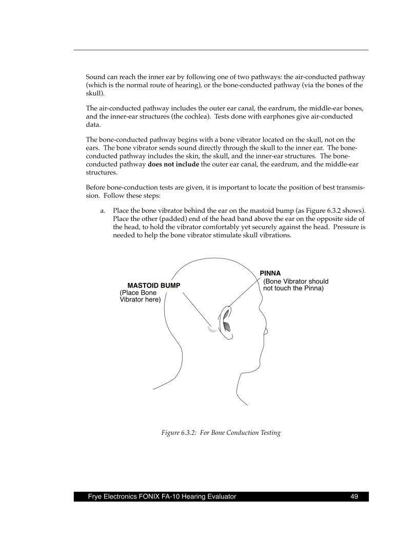
Frye Electronics FONIX FA-10 Hearing Evaluator 49
Sound can reach the inner ear by following one of two pathways: the air-conducted pathway (which is the normal route of hearing), or the bone-conducted pathway (via the bones of the skull).
The air-conducted pathway includes the outer ear canal, the eardrum, the middle-ear bones, and the inner-ear structures (the cochlea). Tests done with earphones give air-conducted data.
The bone-conducted pathway begins with a bone vibrator located on the skull, not on the ears. The bone vibrator sends sound directly through the skull to the inner ear. The bone-conducted pathway includes the skin, the skull, and the inner-ear structures. The bone-conducted pathway does not include the outer ear canal, the eardrum, and the middle-ear structures.
Before bone-conduction tests are given, it is important to locate the position of best transmis-sion. Follow these steps:
a. Place the bone vibrator behind the ear on the mastoid bump (as Figure 6.3.2 shows). Place the other (padded) end of the head band above the ear on the opposite side of the head, to hold the vibrator comfortably yet securely against the head. Pressure is needed to help the bone vibrator stimulate skull vibrations.
PINNA
MASTOID BUMP(Place BoneVibrator here)
(Bone Vibrator shouldnot touch the Pinna)
Figure 6.3.2: For Bone Conduction Testing

50 Chapter 6: Hearing Tests with the Hearing Evaluator
b. Press the Reverse button under the Hearing Level control to activate the tone.
c. With the vibrator in its original position on the mastoid, ask the patient if they hear the tone. When the patient responds, “Yes, I hear it,” tell the patient, “I want to find the best place to put the vibrator. Tell me where the sound is the loudest.” Move the vibrator around on the mastoid and find the point where the sound is the loud-est to the patient. Be sure the vibrator never touches the external ear (pinna). Give the bone-conducted tests from this point of best transmission.
d. The sound made by the bone vibrator goes through the skull to both ears. The sound is normally a little louder in the ear closest to the vibrator, but this is not necessarily the case. The tester must be sure whether the right ear or the left ear responds to the test signal. Ask the patient, “In which ear are you hearing the sound?” You may have to use masking in the non-test ear (see later).
e. Press the Reverse button to turn the tone off before proceeding with the tests.
Bone-conduction threshold tests are given using the same procedure used with the air-con-duction testing.
1. Instruct the patient how to respond, for example, “When you hear the tone, say ‘yes.’”
2. Present an easy-to-hear sound.
3. If needed, encourage the patient to respond quickly yet accurately.
4. Decrease the hearing level in 10-dB steps between presentations until the tone is no longer audible. (Be sure to vary the time between presentations to avoid a rhythmic pattern.)
5. Then increase the hearing level in 5-dB steps between presentations until the patient again responds.
6. Repeat the down-10/up-5 sequence until you have crossed the threshold at least three times.
The threshold is defined as the lowest hearing level the patient can hear fifty-percent of the time. If you any question about the level of the threshold, make several additional passes with the signal from audible to inaudible.
Determine the bone-conducted threshold at 1000 Hz first, then measure the thresholds at the other frequencies, following the same sequence outlined for the air-conducted tests: 1000, 500, 250, repeat 1000 Hz, then 2000, and 4000 Hz. Be sure to record the value of the threshold when each test is given. Place the bone-conduction symbols beside, not directly on top of, the air-conduction symbols on the audiogram sheet.
Bone-conduction thresholds are compared with the air-conduction thresholds to determine the type of hearing loss. The air thresholds will always be equal to or worse than the bone levels. The difference between air- and bone-conduction thresholds is called the “air-bone gap.”
Frye Electronics FONIX FA-10 Hearing Evaluator 51
Masking with bone-conduction puretone tests
Whenever the difference between the air-conduction and the bone-conduction thresholds (the air-bone gap) is greater than 10 dB, you must use masking noise in the non-test ear. With puretone bone-conduction tests, use the “Narrow Band Noise” Input setting and the “Phone” Output setting on the non-test side for masking the non-test ear. Note: The non-test ear will be covered with an earphone to deliver the masking noise, but the test signal is delivered to the test ear by the bone vibrator. Be certain not to cover the test ear with an earphone. Place the earphone on the side of head, above the test ear, and adjust the headband. If the test ear is covered during bone-conduction testing, the results will be invalid. See Section 6.5 for further instructions on setting masking levels.
6 .4 Supra-Threshold (above threshold) TestsSpeech signals are used to obtain the MCL (Most Comfortable Level), the UCL (Uncomfort-able Level), and the SDS (Speech Discrimination Score). Below are the audiometer settings for the three supra-threshold tests. Note that the initial hearing level is different for each test.
Audiometer Settings
Input: Mic (for live voice) or External (for recorded voice)
Output: Phone
Hearing Level: Initial settings: MCL: SRT + 10 dB UCL: 75 dB SDS: Level of best word recognition
Hearing Aid Simulator: Off
Reverse (near “-2.5 dB” button): On
Adjust the Mic or External trim controls (on upper panel near VU meters) so that when you present the words, the VU meter indicates the “0” level.
6 .4 .1 The Most Comfortable Level (MCL) for SpeechWe do the MCL test by allowing the patient to listen to a sample of speech and then asking the patient if the loudness of the speech is comfortable. Begin with the hearing level at least 10 dB above the SRT. The conversation between the tester and the patient might sound like this:
“You are doing very well. Next, I want to find the level of sound you like. Pretend you are listening to a radio or TV. Tell me if you like this loudness level or if you prefer it louder or softer?”
Adjust the hearing level up and down in 5- or 10-dB steps, allowing the patient to choose the level most comfortable for her/him. The first selection is never recorded, as patients often change their mind after listening to various levels. Bracket the MCL by presenting levels a-little-higher-than MCL and a-little-less-than MCL.
Repeat this procedure on the other ear and record your results.
52 Chapter 6: Hearing Tests with the Hearing Evaluator
6 .4 .2 The Uncomfortable Level (UCL) for SpeechThe UCL is the level at which the patient says the sound is uncomfortably loud. Approach this test cautiously. Some patients do not like loud sounds and they can become angered quickly if they are exposed to a sudden loud sound. At a comfortable setting, tell the patient, “So far we have measured your hearing at soft levels and at medium-loud levels. Next, we need to see how your ears respond to louder sounds. I am going to turn the volume up, and you tell me if the words get a little louder, a lot louder or painfully louder.”
Be sure your patient understands what you are doing, then proceed. Adjust the hearing level to 75 dB and ask the patient. “How loud is this level?”
If the patient responds, “loud,” increase the level to 80 dB and say, I want you to tell me how loud I sound to you. Is my voice a little loud, loud-loud, or terribly loud?”
The typical patient reaction is a complaint, like “real loud.”
Adjust the hearing level (up or down) depending upon the patient’s reaction. Find the level the patient describes as, “more than a little loud but less than terribly loud.”
Note: The same test can be made using pulsed puretones, to get estimates of the UCLs for each frequency.
6 .4 .3 The Speech Discrimination Score (SDS)The Speech Discrimination Score is a measure of the patient’s ability to recognize words. The tester presents a word and the patient repeats the word.
The SDS can be tested with live or recorded speech materials. A live-voice SDS can be obtained only if the tester and the patient are placed in separate rooms. The acoustical separation between the patient and the tester must be good enough so the patient is not able to hear the tester’s voice, except through the audiometer. If you are using live voice, be sure also that the patient cannot see the tester’s lips. Otherwise, the test will be invalid.
Instead of using live voice, the SDS can be obtained with a pre-recorded test list. The recorded-test procedure assures a consistent, clear presentation, but provides less personal interaction between the tester and the patient. A recorded test must be used if the tester is not able to use separate rooms, providing an acoustical barrier between the tester and the patient.
The words used for this test are called phonetically balanced (PB) words. (See Appendix D.) Before the test can be given, PB words are presented to the patient at various hearing levels to lo-cate the level which produces the best word recognition ability. This level is called the “PB-max” level.
The test is done by presenting fifty words to the patient at PB-max. Each word is presented in a sentence, not in isolation. The carrier phrase, “Say the word __” is used to convey the test word. Adjust the Mic (for live voice) or External (for recorded voice) trim pot near the VU meter so the last word of the phrase, “Say the word __” registers at O VU.
Frye Electronics FONIX FA-10 Hearing Evaluator 53
Your instructions to the patient might sound like this:
“I am going to present some words and I want you to repeat them. If you are not sure what the word is, guess at the word.”
The patient must correctly repeat every sound in the word. For example, if the test words is “twins” and the patient omits the final “s,” the word is scored as a missed word. Each of the fifty words is worth 2% toward the total score.
Obtain the SDS for the better ear first; masking may be needed when testing the poorer ear (see Section 6.5).
The tester must have good hearing and an excellent monitoring earphone. Without good hearing and a quality earphone, the SDS score is more a function of the tester’s ability to rec-ognize words rather than the patient’s abilities.
Speech discrimination testing must be done in the patient’s native language or dialect.
Masking with Speech Discrimination Score tests
When one ear has better hearing than the other ear, you must use masking noise in the non-test ear under certain conditions. Use masking in the non-test ear (better ear) if either of the two following conditions occurs: 1) When the presentation level (at PB-max) for the sen-tences in the test ear (poorer ear) and the SRT of the non-test ear (better ear) differ by 45 dB or more; or 2) When the presentation level for the sentences in the test ear (poorer ear) and the puretone-average* air- or bone-conduction threshold of the non-test ear differ by 45 dB or more. With the SDS test, use “Speech Noise” for masking the non-test ear. The minimum Hearing Level setting to use for the masking channel is 30 dB below the presentation level (at PB-max) in the test ear. Add to this minimum level the value of the average air-bone gap for 500, 1000, and 2000 Hz in the non-test ear.**
6 .5 Setting the Masking Levels for ThresholdsMasking is an important part of many hearing tests. Hearing tests can be contaminated by “cross hearing,” a condition where the non-test ear responds to a signal presented to the test ear. Masking must be used to stop cross hearing, which can occur in air-conduction testing or bone-conduction testing, using speech or tones. Rules for when to mask are given above in the instructions for each test. Two procedures for setting the masking levels for testing thresholds are given on the following pages.
* The puretone average is the average of the thresholds at 500, 1000 and 2000. ** The “air-bone gap” is the difference between the air- and bone-conduction thresholds.

54 Chapter 6: Hearing Tests with the Hearing Evaluator
6 .5 .1 The Plateau ProcedureAudiometer Settings — Non-Test Ear Side (the ear receiving the masking)
Input: For puretone thresholds: Narrow Band Noise For SRT: Speech Noise
Output: Phone
Hearing Level: Initial setting: 0 dB, or near threshold
Hearing Aid Simulator: Off
Reverse (near “-2.5 dB” button): On
1. From a low setting of the Hearing Level dial, gradually increase the level until the pa-tient indicates he or she can just begin to hear the masking noise. (When using Speech Noise, this level should be near the SRT of the non-test ear; when using Narrow Band Noise, this level should be near the air-conduction puretone threshold of the non-test ear.
2. Now slowly raise the masking level by 15 dB. This is the beginning masking level.
3. Obtain the threshold in the test ear.
4. Now raise the masking level in the non-test ear by 5 dB.
5. Once again, obtain the threshold in the test ear.
6. Repeat steps 4 and 5 until the same threshold level in the test ear is obtained for 3 consecutive settings of the masking noise (this is the “plateau”). If a plateau is never reached, you cannot obtain a valid threshold.
6 .5 .2 The One-Level MethodIn some instances a simple, effective, one-level masking rule can be used. IMPORTANT: There are two restrictions for this method: 1) Do not use the one-level method when testing bone-conduction at the highest hearing levels of the audiometer. 2) You must be certain that the non-test ear (the better ear) has no conductive pathology (no air-bone gap* greater than 10 dB). When in doubt, use the Plateau Procedure.
Simply stated, the One-Level Method is:
“Put a 70-dB level of effective masking noise into the non-test ear.”
Why 70? A signal coming from the test-ear side of the head would have to arrive at the non-test ear at a level higher than 70 dB HL in order to be audible in the non-test ear. This is not likely because the maximum signal level of the audiometer is 110 dB HL, and the attenuation between ears is more than 40 dB.
*The "air-bone gap" is the difference between air- and bone-conduction thresholds.
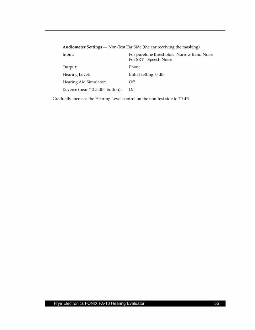
Frye Electronics FONIX FA-10 Hearing Evaluator 55
Audiometer Settings — Non-Test Ear Side (the ear receiving the masking)
Input: For puretone thresholds: Narrow Band Noise For SRT: Speech Noise
Output: Phone
Hearing Level: Initial setting: 0 dB
Hearing Aid Simulator: Off
Reverse (near “-2.5 dB” button): On
Gradually increase the Hearing Level control on the non-test side to 70 dB.

Frye Electronics FONIX FA-10 Hearing Evaluator 57
Appendix A: Operational Indicators & Error Messages
Green LEDs – Operational IndicatorsThe green LEDs on the front panel indicate the operational condition of the audiometer. There are ten green LEDs. They have the following meanings:
Power LED on: Power is applied to the audiometer.
Left Stimulus LED on: The left channel has been activated.
Right Stimulus LED on: The right channel has been activated.
Output Reverse, Pulse, Warble, and/or Talk Forward LEDs on: The associated function is engaged.
Response LED on: The patient has pressed the response button.
Left Hearing Aid Simulator LED on: The left hearing aid simulator is engaged.
Right Hearing Aid Simulator LED on: The right hearing aid simulator is engaged.
Left Hearing Aid Simulator LED is flashing at a 1/10 second rate: The audiometer is in calibration mode.
Left and/or Right Hearing Aid Simulator LEDs flashing at a 1/4 second rate with momentary one-second pause:
An EEROM failure has occurred, calibration may not be reliable. See Calibration Storage Errors below.
Both Hearing Aid Simulator LEDs flashing rapidly: The secondary earphone calibration is selected. This flashing is a reminder to use the correct transducer.
58 AppendixA:OperationalIndicators&ErrorMessages
Red LEDs – Error MessagesThe red LEDs on the front panel are used to indicate error conditions. There are three error LEDs. They have the following meanings:
Operational Errors
Problem: Left Level LED flashing at a 1/10 second rate: The left level is out of calibra-tion.
Right Level LED flashing at a 1/10 second rate: The right level is out of cali-bration.
Cause: The current level setting is beyond the ability of the audiometer to output a calibrated signal. (The current signal output is at the maximum level possible for the selected transducer.)
Cure: Reduce the Hearing Level.
Problem: Frequency and Left Level LED flashing 1/10th second rate: The left channel selection is not a valid selection.
Frequency and Right Level LED flashing 1/10th second rate: The right chan-nel selection is not a valid selection.
Cause: The current mode setting is not a valid selection. (The current signal output is at the minimum level possible for the selected transducer.)
Cure: Change the selected mode. Change frequency, Input, or Output selector to appropriate setting.
Problem: Frequency plus Left Level LED on continuously: The left channel is under RS232 control.
Frequency plus Right Level LED on continuously: The right channel is under RS232 control.
Frequency plus Left Level plus Right Level LED on continuously: Both chan-nels are under RS232 control.
Cause: This is not a true error condition, rather it is a warning. It indicates that the front panel controls are no longer controlling the instrument, so the settings cannot be relied on as being valid. Control is being managed by the attached computer through the RS232 computer interface.
Frye Electronics FONIX FA-10 Hearing Evaluator 59
Cure: The computer can return control to the audiometer front panel controls at anytime, or the instrument can be turned off then back on to force a return to normal front panel operation.
Equipment Errors
Problem: Left Level LED continuously flashing at 1/4 second rate: The left level switch is generating an invalid code.
Right Level LED continuously flashing at 1/4 second rate: The right level switch is generating an invalid code.
Frequency LED continuously flashing at 1/4 second rate: The frequency switch is generating an invalid code.
Cause: The associated switch is generating an invalid (non-existing) selection. The switch may be defective.
Cure: Change the switch position. If the problem does not go away, the switch may be defective and should be replaced by a qualified service technician.
Problem: Left level, Right level, and Frequency LEDs all flashing at a 1/4 second rate with or without a periodic one second pause or All LEDs (except power and response) flashing at a 1/10 second rate:
Cause: System failure has occurred, LEDs are indicating the error number by the flash count.
Cure: Turn the audiometer off then back on. If the problem does not go away, the audiometer is not operational and must be repaired by a qualified service technician. You may want to write down the flash count to help the service technician localize the problem.
Problem: All LEDs (except response) are on continuously:
Cause: While the power-on test sequence is being performed, all the front panel LEDs (except the response LED) will turn on and stay on until the test has been completed. When the audiometer self-test is complete and the instru-ment is ready to use, all the LEDs except the power LED will turn off. (De-pending on the switch positions, some LEDs may remain on.)
Cure: If all the LEDs stay on, or the audiometer repeatedly turns all the LEDs on then off, the audiometer is not operational and must be repaired by a quali-fied service technician. The audiometer will not be operational until the problem has been corrected.
60 AppendixA:OperationalIndicators&ErrorMessages
Calibration Storage (EEROM) Errors
Problem: Left and Right Hearing Aid Simulator LEDs (green) flashing at a 1/4 second rate with periodic one second pause. In addition the Left level, Right level, and Frequency (red) LEDs may flash momentarily at a one second or three second rate:
Cause: An EEROM error has occurred, LEDs are indicating the error number by the flash count. (Note: Only the right simulator LED flashes a count when in cali-bration mode since left simulator LED indicates calibration mode is enabled.)
Cure: Turn the audiometer off then back on. If the problem does not go away, the audiometer is not operational and must be recalibrated or repaired by a quali-fied service technician.
The Hearing aid flash count is defined as follows:
Warning — 1, 2, or 3: Recoverable EEROM error - calibration OK.
Error — 4 or 5: Non-recoverable error - using factory calibration.
Failure — 6 or 7: EEROM failure - using default calibration.
An EEROM warning error indicates that a recoverable failure occurred. One of the tables contains defective data. Typically this can be corrected by recalibrating the audiometer. In the meantime the audiometer can still be operated since the calibration information was recover-able.
An EEROM Error indicates that the calibration information was not recoverable. As a back-up, the audiometer will revert to the original factory calibration values. This means that the audiometer may not be in full calibration, since any calibration adjustments that were done since the last factory calibration will be lost. The audiometer is still operable, but at a poten-tially reduced accuracy. Usually this can be corrected by recalibrating the audiometer.
The most serious failure is a complete EEROM failure. If no valid calibration data can be read from the EEROM, the audiometer will revert to a default calibration configuration. The audiometer will still be operable, but the calibration accuracy will be reduced. A hardware failure requires that the EEROM be replaced by a qualified service technician and that a com-plete recalibration of the audiometer be performed. The default calibration table contains the average calibration values for the transducers specified for use with the audiometer. While the default calibration table will prevent excessive calibration errors from being loaded from a bad EEROM, it should not be relied on as a valid calibration value.
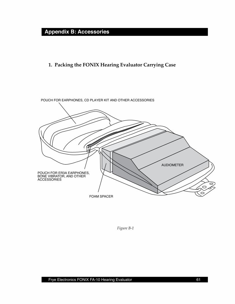
Frye Electronics FONIX FA-10 Hearing Evaluator 61
Appendix B: Accessories
1 . Packing the FONIX Hearing Evaluator Carrying Case
Figure B-1
POUCH FOR EARPHONES, CD PLAYER KIT AND OTHER ACCESSORIES
POUCH FOR ER3A EARPHONES,BONE VIBRATOR, AND OTHER ACCESSORIES
FOAM SPACER
AUDIOMETER

62 Appendix B: Accessories
2 . Using an iPod or Compact Disk Recordings with the Hearing Evaluator .
HeadphonesConnect an iPod or CD player to the Hearing Evaluator as shown in figure B-2. Be sure to use the line out jack on the CD player (if it has this option) on the phones jack. The iPod should be connected to a dock with a line-out. See section 4.8. Turn the Input knob to External on both sides of the audiometer. Set the Output to phones on each side of the audiometer. Push the Reverse button under Hearing Level on both sides. Insert CD into player. Start the CD player or iPod. When you hear the calibration tone, adjust the External knob found next to the VU meters until the light is at 0 dB on both sides of the audiometer. Do not use a player with external speakers unless they can be disabled on disconnected.
The output of tracks with two channels can be redirected with the use of the right and left external input controls. Proceed to test as desired.
SpeakersThe speakers have been precalibrated at the factory for use at one meter from the client. It is not necessary to readjust the external knob next to the VU meter when switching to speaker.
NOTE: Some CD players may exhibit a significant amount of “cross-talk” when connected to the au-diometer. This problem is most noticable when the CD has a different left and right program on the same channel/track.
To confirm this problem:
Disconnect one of the CD player external outputs going to the audiometer input on the rear panel of the audiometer.
To remedy the problem:
Set the Input knob to Right External for the left ear. Leave the right ear Input at External. To listen to the other track, set the left ear Input to External and the right ear Input to Left Exter-nal.

Frye Electronics FONIX FA-10 Hearing Evaluator 63
Figure B-2: Connections to the Hearing Evaluator from External Sources
RS232 COMPUTERINTERFACE
MANUFACTURED BY
FRYE ELECTRONICS, INC.Hearing Evaluatorô Model FA-10Audiometer: Type 3Bone Vibrator: Radioear B-71Serial #Made in Tigard, Oregon, USA
CAUTION: FOR CONTINUED PROTECTION AGAINST FIREHAZARD, REPLACE ONLY WITH 1/2 AMP SLOW 250V FUSE
LEFTSPEAKER
8Ω
LEFTPHONE
100Ω
RIGHTPHONE
100Ω
RIGHTSPEAKER
8Ω
BONE100Ω
STEREOMONITORPHONES
TALK BACKMICROPHONE
LEFTEXTERNALSOURCE
RIGHTEXTERNALSOURCE
PATIENTRESPONSE
SWITCH
OUTPUT INPUT
105-130 V~ 60 Hz 60 WATTS MAXIMUM
GROUNDING RELIABILITY CAN ONLY BE ACHIEVED WHEN THEEQUIPMENT IS CONNECTED TO AN EQUIVALENT RECEPTACLEMARKED HOSPITAL ONLY OR HOSPITAL GRADE.
!!!!
CD PLAYER
SPEAKER CABLES,RCA TO 1/4" PHONE PLUG
Y-ADAPTER CABLE,3.5 MM TO DUAL 1/4"
Red plug goes toRight External Source
PORTABLE CD PLAYER ORIPOD WITH DOCK
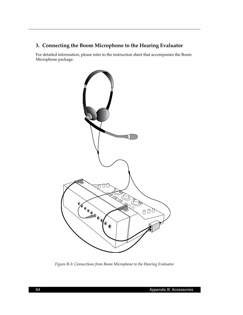
64 Appendix B: Accessories
3 . Connecting the Boom Microphone to the Hearing EvaluatorFor detailed information, please refer to the instruction sheet that accompanies the Boom Microphone package.
Figure B-3: Connections from Boom Microphone to the Hearing Evaluator
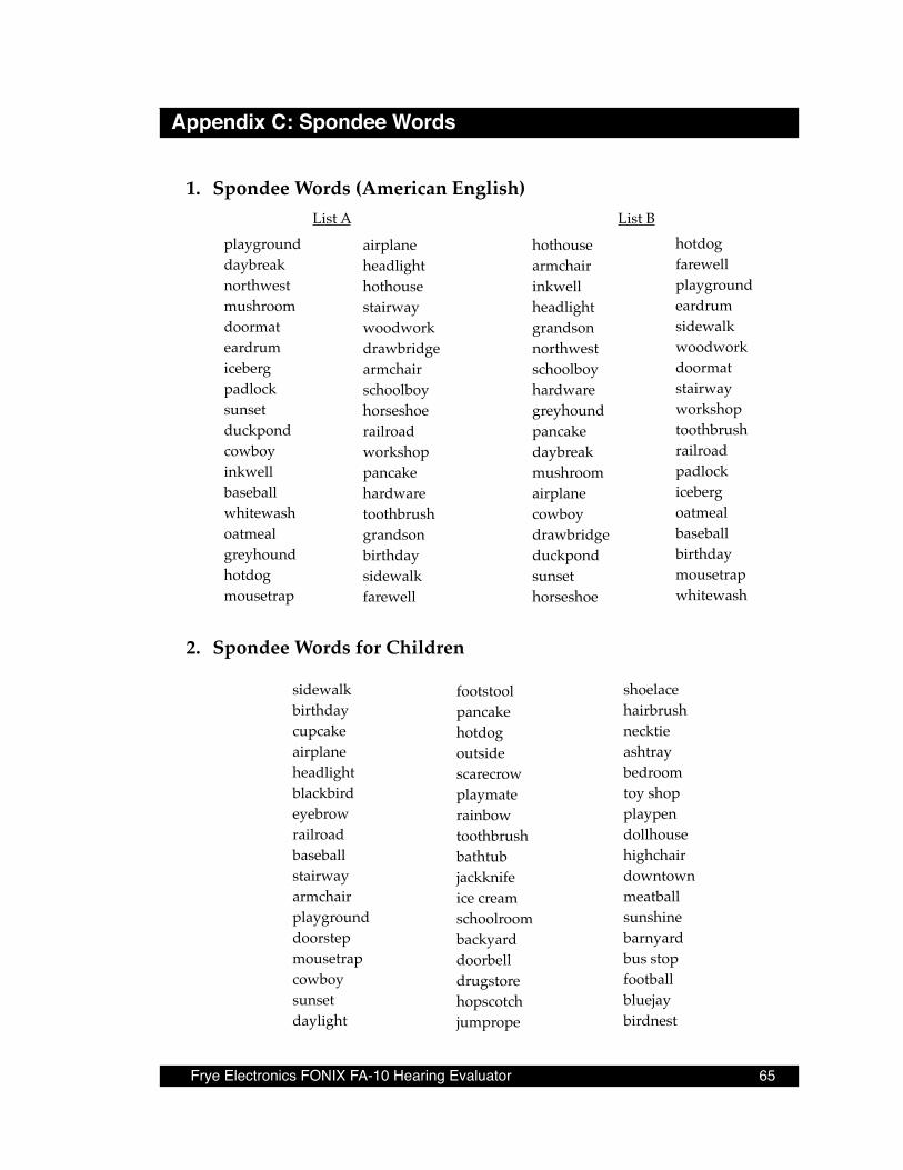
Frye Electronics FONIX FA-10 Hearing Evaluator 65
Appendix C: Spondee Words
2 . Spondee Words for Children
playgrounddaybreaknorthwestmushroomdoormateardrumicebergpadlocksunsetduckpondcowboyinkwellbaseballwhitewashoatmealgreyhoundhotdogmousetrap
airplaneheadlighthothousestairwaywoodworkdrawbridgearmchairschoolboyhorseshoerailroadworkshoppancakehardwaretoothbrushgrandsonbirthdaysidewalkfarewell
List Ahotdogfarewellplaygroundeardrumsidewalkwoodworkdoormatstairwayworkshoptoothbrushrailroadpadlockicebergoatmealbaseballbirthdaymousetrapwhitewash
List B
hothousearmchairinkwellheadlightgrandsonnorthwestschoolboyhardwaregreyhoundpancakedaybreakmushroomairplanecowboydrawbridgeduckpondsunsethorseshoe
1 . Spondee Words (American English)
footstoolpancakehotdogoutsidescarecrowplaymaterainbowtoothbrushbathtubjackknifeice creamschoolroombackyarddoorbelldrugstorehopscotchjumprope
sidewalkbirthdaycupcakeairplaneheadlightblackbirdeyebrowrailroadbaseballstairwayarmchairplaygrounddoorstepmousetrapcowboysunsetdaylight
shoelacehairbrushnecktieashtraybedroomtoy shopplaypendollhousehighchairdowntownmeatballsunshinebarnyardbus stopfootballbluejaybirdnest

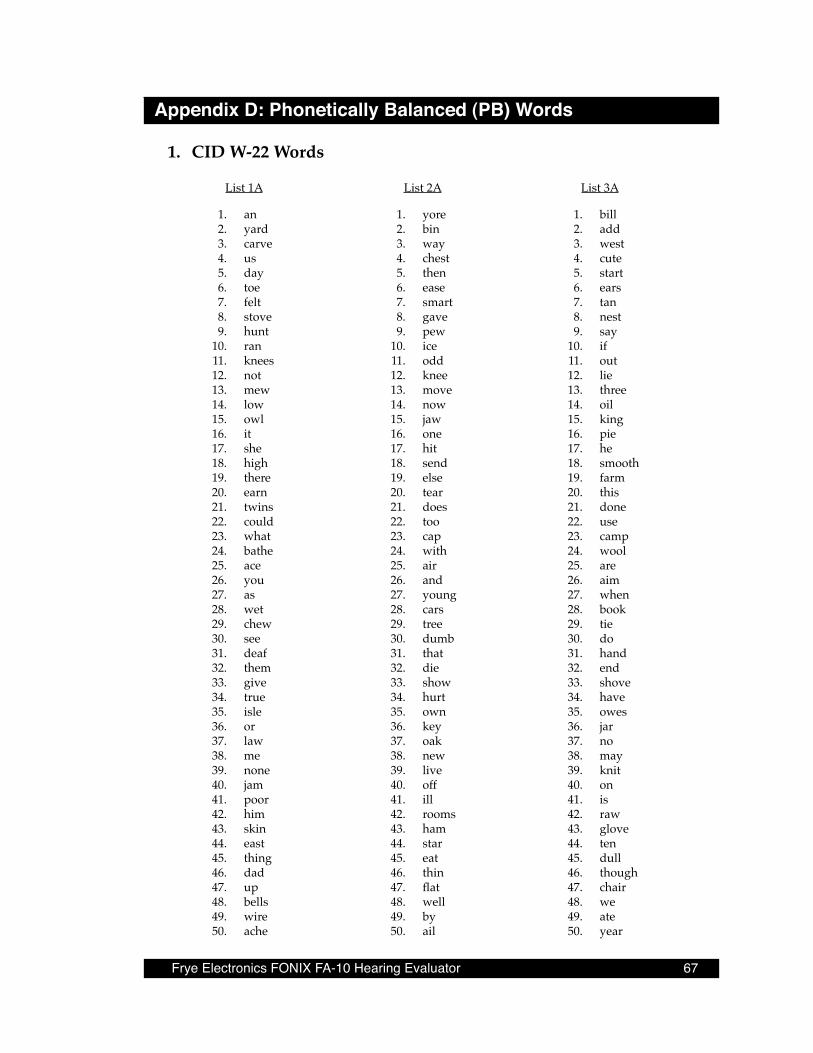
Frye Electronics FONIX FA-10 Hearing Evaluator 67
Appendix D: Phonetically Balanced (PB) Words
List 3A
1. bill 2. add 3. west 4. cute 5. start 6. ears 7. tan 8. nest 9. say 10. if 11. out 12. lie 13. three 14. oil 15. king 16. pie 17. he 18. smooth 19. farm 20. this 21. done 22. use 23. camp 24. wool 25. are 26. aim 27. when 28. book 29. tie 30. do 31. hand 32. end 33. shove 34. have 35. owes 36. jar 37. no 38. may 39. knit 40. on 41. is 42. raw 43. glove 44. ten 45. dull 46. though 47. chair 48. we 49. ate 50. year
List 2A
1. yore 2. bin 3. way 4. chest 5. then 6. ease 7. smart 8. gave 9. pew 10. ice 11. odd 12. knee 13. move 14. now 15. jaw 16. one 17. hit 18. send 19. else 20. tear 21. does 22. too 23. cap 24. with 25. air 26. and 27. young 28. cars 29. tree 30. dumb 31. that 32. die 33. show 34. hurt 35. own 36. key 37. oak 38. new 39. live 40. off 41. ill 42. rooms 43. ham 44. star 45. eat 46. thin 47. flat 48. well 49. by 50. ail
List 1A
1. an 2. yard 3. carve 4. us 5. day 6. toe 7. felt 8. stove 9. hunt 10. ran 11. knees 12. not 13. mew 14. low 15. owl 16. it 17. she 18. high 19. there 20. earn 21. twins 22. could 23. what 24. bathe 25. ace 26. you 27. as 28. wet 29. chew 30. see 31. deaf 32. them 33. give 34. true 35. isle 36. or 37. law 38. me 39. none 40. jam 41. poor 42. him 43. skin 44. east 45. thing 46. dad 47. up 48. bells 49. wire 50. ache
1 . CID W-22 Words

68 Appendix D: Phonetically Balanced Words
2 . NU Auditory Test #6
List 1A
1. laud 2. boat 3. pool 4. nag 5. limb 6. shout 7. sub 8. vine 9. dime 10. goose 11. whip 12. tough 13. puff 14. keen 15. death 16. sell 17. take 18. fall 19. raise 20. third 21. gap 22. fat 23. met 24. jar 25. door 26. love 27. sure 28. knock 29. choice 39. hash 31. lot 32. raid 33. hurl 34. moon 35. page 36. yes 37. reach 38. king 39. home 40. rag 41. which 42. week 43. size 44. mode 45. bean 46. tip 47. chalk 48. jail 49. burn 50. kite
List 2A
1. pick 2. room 3. nice 4. said 5. fail 6. south 7. white 8. keep 9. dead 10. loaf 11. dab 12. numb 13. juice 14. chief 15. merge 16. wag 17. rain 18. witch 19. soap 20. young 21. ton 22. keg 23. calm 24. tool 25. pike 26. mill 27. hush 28. shack 29. read 30. rot 31. hate 32. live 33. book 34. voice 35. gaze 36. pad 37. thought 38. bought 39. turn 40. chair 41. lore 42. bite 43. haze 44. match 45. learn 46. shawl 47. deep 48. gin 49. goal 50. far
List 3A
1. base 2. mess 3. cause 4. mop 5. good 6. luck 7. walk 8. youth 9. pain 10. date 11. pearl 12. search 13. ditch 14. talk 15. ring 16. germ 17. life 18. team 19. lid 20. pole 21. road 22. shall 23. late 24. cheek 25. beg 26. love 27. sure 28. knock 29. choice 30. hash 31. lot 32. raid 33. hurl 34. moon 35. page 36. yes 37. reach 38. king 39. home 40. rag 41. which 42. week 43. size 44. mode 45. bean 46. tip 47. chalk 48. jail 49. burn 50. kite
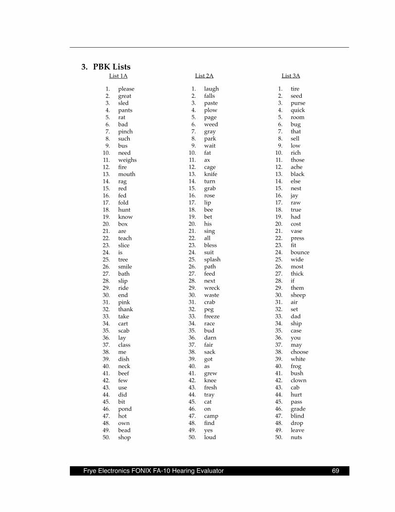
Frye Electronics FONIX FA-10 Hearing Evaluator 69
3 . PBK ListsList 3A
1. tire 2. seed 3. purse 4. quick 5. room 6. bug 7. that 8. sell 9. low 10. rich 11. those 12. ache 13. black 14. else 15. nest 16. jay 17. raw 18. true 19. had 20. cost 21. vase 22. press 23. fit 24. bounce 25. wide 26. most 27. thick 28. if 29. them 30. sheep 31. air 32. set 33. dad 34. ship 35. case 36. you 37. may 38. choose 39. white 40. frog 41. bush 42. clown 43. cab 44. hurt 45. pass 46. grade 47. blind 48. drop 49. leave 50. nuts
List 1A
1. please 2. great 3. sled 4. pants 5. rat 6. bad 7. pinch 8. such 9. bus 10. need 11. weighs 12. fire 13. mouth 14. rag 15. red 16. fed 17. fold 18. hunt 19. know 20. box 21. are 22. teach 23. slice 24. is 25. tree 26. smile 27. bath 28. slip 29. ride 30. end 31. pink 32. thank 33. take 34. cart 35. scab 36. lay 37. class 38. me 39. dish 40. neck 41. beef 42. few 43. use 44. did 45. bit 46. pond 47. hot 48. own 49. bead 50. shop
List 2A
1. laugh 2. falls 3. paste 4. plow 5. page 6. weed 7. gray 8. park 9. wait 10. fat 11. ax 12. cage 13. knife 14. turn 15. grab 16. rose 17. lip 18. bee 19. bet 20. his 21. sing 22. all 23. bless 24. suit 25. splash 26. path 27. feed 28. next 29. wreck 30. waste 31. crab 32. peg 33. freeze 34. race 35. bud 36. darn 37. fair 38. sack 39. got 40. as 41. grew 42. knee 43. fresh 44. tray 45. cat 46. on 47. camp 48. find 49. yes 50. loud

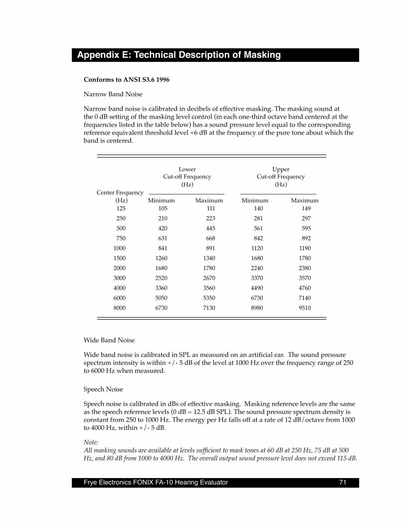
Frye Electronics FONIX FA-10 Hearing Evaluator 71
Appendix E: Technical Description of Masking
Conforms to ANSI S3 .6 1996
Narrow Band Noise
Narrow band noise is calibrated in decibels of effective masking. The masking sound at the 0 dB setting of the masking level control (in each one-third octave band centered at the frequencies listed in the table below) has a sound pressure level equal to the corresponding reference equivalent threshold level +6 dB at the frequency of the pure tone about which the band is centered.
Lower Upper Cut-off Frequency Cut-off Frequency (Hz) (Hz)
Center Frequency (Hz) Minimum Maximum Minimum Maximum
125 105 111 140 149 250 210 223 281 297 500 420 445 561 595 750 631 668 842 892 1000 841 891 1120 1190 1500 1260 1340 1680 1780 2000 1680 1780 2240 2380 3000 2520 2670 3370 3570 4000 3360 3560 4490 4760 6000 5050 5350 6730 7140 8000 6730 7130 8980 9510
Wide Band Noise
Wide band noise is calibrated in SPL as measured on an artificial ear. The sound pressure spectrum intensity is within +/- 5 dB of the level at 1000 Hz over the frequency range of 250 to 6000 Hz when measured.
Speech Noise
Speech noise is calibrated in dBs of effective masking. Masking reference levels are the same as the speech reference levels (0 dB = 12.5 dB SPL). The sound pressure spectrum density is constant from 250 to 1000 Hz. The energy per Hz falls off at a rate of 12 dB/octave from 1000 to 4000 Hz, within +/- 5 dB.
Note: All masking sounds are available at levels sufficient to mask tones at 60 dB at 250 Hz, 75 dB at 500 Hz, and 80 dB from 1000 to 4000 Hz. The overall output sound pressure level does not exceed 115 dB.

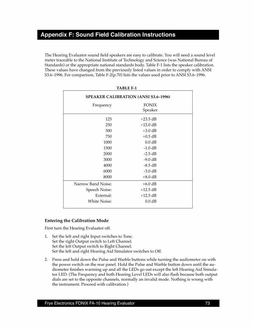
Frye Electronics FONIX FA-10 Hearing Evaluator 73
Appendix F: Sound Field Calibration Instructions
The Hearing Evaluator sound field speakers are easy to calibrate. You will need a sound level meter traceable to the National Institute of Technology and Science (was National Bureau of Standards) or the appropriate national standards body. Table F-1 lists the speaker calibration. These values have changed from the previously listed values in order to comply with ANSI S3.6–1996. For comparison, Table F-2(p.70) lists the values used prior to ANSI S3.6–1996.
TABLE F-1
SPEAKER CALIBRATION (ANSI S3 .6–1996)
Frequency FONIX Speaker
125 +23.5 dB 250 +12.0 dB 500 +3.0 dB 750 +0.5 dB 1000 0.0 dB 1500 -1.0 dB 2000 -2.5 dB 3000 -9.0 dB 4000 -8.5 dB 6000 -3.0 dB 8000 +8.0 dB Narrow Band Noise: +6.0 dB Speech Noise: +12.5 dB External: +12.5 dB White Noise: 0.0 dB
Entering the Calibration ModeFirst turn the Hearing Evaluator off.
1. Set the left and right Input switches to Tone. Set the right Output switch to Left Channel. Set the left Output switch to Right Channel. Set the left and right Hearing Aid Simulator switches to Off.
2. Press and hold down the Pulse and Warble buttons while turning the audiometer on with the power switch on the rear panel. Hold the Pulse and Warble button down until the au-diometer finishes warming up and all the LEDs go out except the left Hearing Aid Simula-tor LED. (The Frequency and both Hearing Level LEDs will also flash because both output dials are set to the opposite channels, normally an invalid mode. Nothing is wrong with the instrument. Proceed with calibration.)
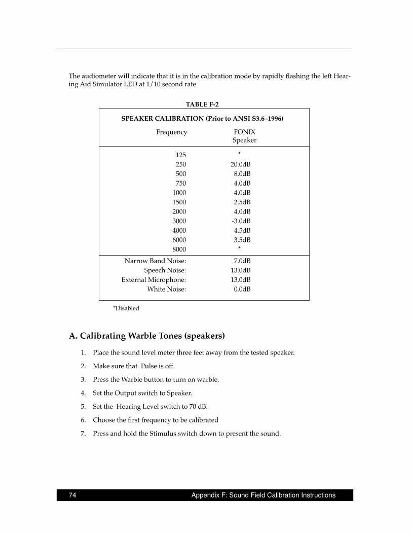
74 Appendix F: Sound Field Calibration Instructions
The audiometer will indicate that it is in the calibration mode by rapidly flashing the left Hear-ing Aid Simulator LED at 1/10 second rate
TABLE F-2
SPEAKER CALIBRATION (Prior to ANSI S3 .6–1996)
Frequency FONIX Speaker
125 * 250 20.0dB 500 8.0dB 750 4.0dB 1000 4.0dB 1500 2.5dB 2000 4.0dB 3000 -3.0dB 4000 4.5dB 6000 3.5dB 8000 * Narrow Band Noise: 7.0dB Speech Noise: 13.0dB External Microphone: 13.0dB White Noise: 0.0dB
*Disabled
A . Calibrating Warble Tones (speakers)
1. Place the sound level meter three feet away from the tested speaker.
2. Make sure that Pulse is off.
3. Press the Warble button to turn on warble.
4. Set the Output switch to Speaker.
5. Set the Hearing Level switch to 70 dB.
6. Choose the first frequency to be calibrated
7. Press and hold the Stimulus switch down to present the sound.
Frye Electronics FONIX FA-10 Hearing Evaluator 75
8. Press either the -2.5 button to reduce the sound level or the Reverse button to increase the sound level. Holding the buttons down longer than one second will cause the sound level to step up or down repeatedly.
9. When you have reached the desired level based on your sound level meter, release the stimulus button and adjust the audiometer settings for the next frequency.
For calibration values refer to Table F-1 above(p.69).
NOTE: Speaker calibration is for speakers measured at three feet for 45 degree azimuth op-eration as specified in ANSI S3.6–1996, Section 9.5, Table 8.
If the calibration level exceeds the ability of the instrument to provide the sound, the Hearing Level LED will flash rapidly. If this happens you must calibrate the audiometer at a lower set-ting on the hearing level dial.
NOTE: If background noise level is higher than 50 dB you may want to calibrate at a higher level to reduce the error from the background noise.
B . Calibrating Speech Noise (speakers)
Speech Noise is calibrated for effective masking of speech.
1. Set Output switch to Speaker.
2. Select Speech Noise at the Input switch for the first speaker. Put the Hearing Level dial at 70 dB. The SPL output on the source level meter should read 82.5 dB for an HL of 70 dB. The SPL to HL equivalent is 12.5 dB for speech noise.
3. Press and hold the Stimulus button down to present the sound.
4. Press either the -2.5 button to reduce the sound level or the Reverse button to increase the sound level. Holding the buttons down longer than one second will cause the sound level to step up or down repeatedly.
5. When you have reached 82.5 dB based on your sound level meter, release the stimulus button.
Calibrate both speakers.
C . Calibrating White Noise (speakers)
White Noise is not calibrated in effective masking. The HL readings on the dial are converted to SPL without any corrections.
1. Set Output switch to Speaker
2. Select White Noise at the Input switch for the first speaker. Set the Hearing Level dial at 70 dB.
76 Appendix F: Sound Field Calibration Instructions
3. Press and hold the Stimulus button down to present the sound.
4. Press either the -2.5 button to reduce the sound level or the Reverse button to increase the sound level. Holding the buttons down longer than one second will cause the sound level to step up or down repeatedly.
5. When you have reached 70 dB based on your sound level meter, release the stimulus button.
Calibrate both speakers.
NOTE: If background noise level is higher than 50 dB you may want to calibrate at a higher level to reduce the error from the background noise.
D . Calibrating Narrow Band Noise (speakers)
Narrow band noise is calibrated as effective masking. The value is determined by adding 6 dB to the SPL value determined in Puretone.
Note: The initial factory default setting for Narrow Band Noise is off. You must press the Re-verse button to get an output for calibration.
1. Set Output switch to Speaker.
2. Select Narrow Band Noise at the Input Switch of the first speaker. Set the Hearing Level dial at 70 dB.
3. Set the Frequency dial to 1000 Hz.
4. Press and hold the Stimulus button down to present the sound.
5. Press either the -2.5 button to reduce the sound level or the Reverse button to increase the sound level. Holding the buttons down longer than one second will cause the sound level to step up or down repeatedly.
6. When you have reached 76 dB based on your sound level meter, you may release the stimulus button.
Calibrate both speakers.
E . Calibrating External
1. Set the output switch to Speaker. When you calibrate external sources (tape or CD), you calibrate the microphone also.
2. Set the Input switch to External and the Hearing Level dial to 70 dB.
3. Apply a 1000 Hz signal to the External input jack. (Use a signal generator or the cali-bration signal from tape or CD.)
4. Adjust the External gain control to set the VU meter to 0 dB.
Frye Electronics FONIX FA-10 Hearing Evaluator 77
5. Press and hold the Stimulus button down to present the sound. The sound level meter should read 82.5 dB at 1 kHz when sound field speakers are properly calibrated.
6. Press either the -2.5 button to reduce the sound level or the Reverse button to increase the sound level. Holding the buttons down longer than one second will cause the sound level to step up or down repeatedly.
Calibrate both speakers.
Calibrating External automatically calibrates the microphone. Refer to Table F-1 for the re-quired calibration values
F . Storing the Calibration and Leaving Calibration Mode
The calibrations you have just performed are stored into the internal EEROM (Electrically Erasable Read Only Memory) by leaving the calibration mode.
1. Set the left and right Source switches to Tone.
2. Set the right Output switch to Left Channel.
3. Set the left Output switch to Right Channel.
4. Set the left and right Hearing Aid Simulator switches to HFE.
5. Press and hold the Pulse and Warble buttons at the same time and hold them down until the left Hearing Aid Simulator LED goes out indicating that the calibration data has been stored and you are out of calibration mode.
Note that the Level error LEDs will be flashing rapidly because of the invalid output selection.
G . Error Indicator
If the calibration did not take, or an incorrect switch combination was selected to exit the cali-bration mode, the left Hearing Aid Simulator LED will remain flashing.
H . How to Cancel Calibration (Discard the calibration values entered)
While still in the calibration mode, simply turn off the power switch and all calibration infor-mation modifications will be discarded.
78 Appendix F: Sound Field Calibration Instructions
I . Restoring the Factory Calibration
Should you make a mistake in calibrating the instrument and want to restore the original fac-tory calibration tables, you can do so by pressing the Output Reverse and Talk Forward but-tons while turning the power on instead of pressing the Pulse and Warble buttons.
J . Calibration Errors
A calibration error is an attempt to exceed the capabilities of the instrument. If the Hearing Level LEDs on the front panel flash rapidly, you have exceeded the limits of that particular combination of input and output. You will have to calibrate at a lower level.
An inadvertent loss of calibration can normally be cured by recalibrating the instrument. The calibration information can be stored over 10,000 times in the EEROM, so that should not be a cause for concern.
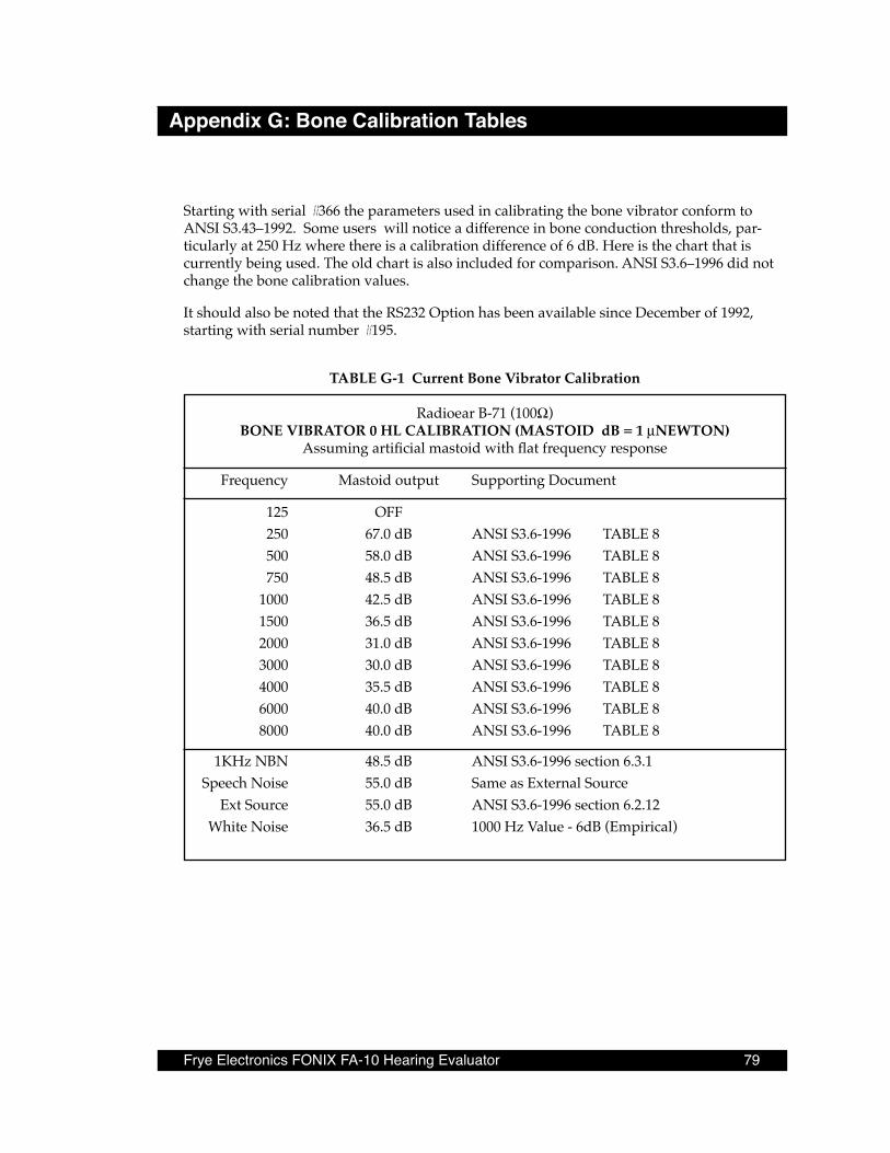
Frye Electronics FONIX FA-10 Hearing Evaluator 79
Appendix G: Bone Calibration Tables
Starting with serial #366 the parameters used in calibrating the bone vibrator conform to ANSI S3.43–1992. Some users will notice a difference in bone conduction thresholds, par-ticularly at 250 Hz where there is a calibration difference of 6 dB. Here is the chart that is currently being used. The old chart is also included for comparison. ANSI S3.6–1996 did not change the bone calibration values.
It should also be noted that the RS232 Option has been available since December of 1992, starting with serial number #195.
TABLE G-1 Current Bone Vibrator Calibration
Radioear B-71 (100Ω)BONE VIBRATOR 0 HL CALIBRATION (MASTOID dB = 1 µNEWTON)
Assuming artificial mastoid with flat frequency response
Frequency Mastoid output Supporting Document
125 OFF 250 67.0 dB ANSI S3.6-1996 TABLE 8 500 58.0 dB ANSI S3.6-1996 TABLE 8 750 48.5 dB ANSI S3.6-1996 TABLE 8 1000 42.5 dB ANSI S3.6-1996 TABLE 8 1500 36.5 dB ANSI S3.6-1996 TABLE 8 2000 31.0 dB ANSI S3.6-1996 TABLE 8 3000 30.0 dB ANSI S3.6-1996 TABLE 8 4000 35.5 dB ANSI S3.6-1996 TABLE 8 6000 40.0 dB ANSI S3.6-1996 TABLE 8 8000 40.0 dB ANSI S3.6-1996 TABLE 8
1KHz NBN 48.5 dB ANSI S3.6-1996 section 6.3.1 Speech Noise 55.0 dB Same as External Source Ext Source 55.0 dB ANSI S3.6-1996 section 6.2.12 White Noise 36.5 dB 1000 Hz Value - 6dB (Empirical)
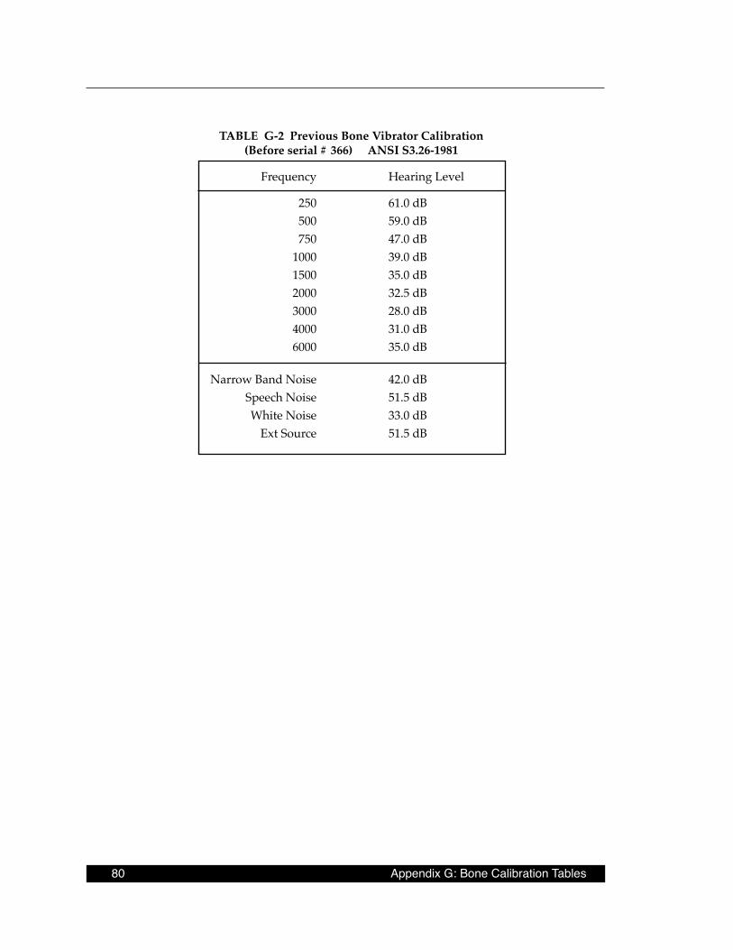
80 Appendix G: Bone Calibration Tables
TABLE G-2 Previous Bone Vibrator Calibration (Before serial # 366) ANSI S3 .26-1981
Frequency Hearing Level
250 61.0 dB 500 59.0 dB 750 47.0 dB 1000 39.0 dB 1500 35.0 dB 2000 32.5 dB 3000 28.0 dB 4000 31.0 dB 6000 35.0 dB
Narrow Band Noise 42.0 dB Speech Noise 51.5 dB White Noise 33.0 dB Ext Source 51.5 dB

Frye Electronics FONIX FA-10 Hearing Evaluator 81
Appendix H: Earphone Calibration Tables
TABLE H-1
Left Channel Earphone Calibration for TDH39 100Ω earphones
tupnItfeL tuptuOtfeL ycneuqerF
tfeLgniraeHleveL
leveLdnuoSsulpreteMrelpuoccc6
enoT enohP 521 Bd07 LPSBd0.511enoT enohP 052 Bd07 LPSBd5.59enoT enohP 005 Bd07 LPSBd5.18enoT enohP 057 Bd07 LPSBd5.77enoT enohP K1 Bd07 LPSBd0.77enoT enohP K5.1 Bd07 LPSBd5.67enoT enohP K2 Bd07 LPSBd0.97enoT enohP K3 Bd07 LPSBd0.08enoT enohP K4 Bd07 LPSBd5.97enoT enohP K6 Bd07 LPSBd5.58enoT enohP K8 Bd07 LPSBd0.38
esioNdnaBworraN enohP K1 Bd07 LPSBd0.38esioNhceepS enohP — Bd07 LPSBd5.98
esioNetihW enohP — Bd07 LPSBd0.07ecruoSlanretxEL
)UVOtes;zHK1txE( enohP — Bd07 LPSBd5.98
TABLE H-2
Left Channel Earphone Calibration for Eartone 3A 50Ω Earphones
tupnItfeL tuptuOtfeL ycneuqerF
tfeLgniraeHleveL
leveLdnuoSsulpreteM
relpuoc8310BDenoT enohP 521 Bd07 LPSBd0.69enoT enohP 052 Bd07 LPSBd0.48enoT enohP 005 Bd07 LPSBd5.57enoT enohP 057 Bd07 LPSBd0.27enoT enohP K1 Bd07 LPSBd0.07enoT enohP K5.1 Bd07 LPSBd0.27enoT enohP K2 Bd07 LPSBd0.37enoT enohP K3 Bd07 LPSBd5.37enoT enohP K4 Bd07 LPSBd5.57enoT enohP K6 Bd07 LPSBd0.27enoT enohP K8 Bd07 LPSBd0.07
esioNdnaBworraN enohP K1 Bd07 LPSBd0.67esioNhceepS enohP — Bd07 LPSBd5.28
esioNetihW enohP — Bd07 LPSBd0.07ecruoSlanretxEL
)UVOtes;zHK1txE( enohP — Bd07 LPSBd5.28

82 Appendix H: Earphone Calibration Tables
TABLE H-3
Right Channel Earphone Calibration for TDH39 100Ω earphones
tupnIthgiRthgiRtuptuO ycneuqerF
thgiRgniraeHleveL
leveLdnuoSsulpreteM
relpuoccc6
enoT enohP 521 Bd07 LPSBd0.511enoT enohP 052 Bd07 LPSBd5.59enoT enohP 005 Bd07 LPSBd5.18enoT enohP 057 Bd07 LPSBd5.77enoT enohP K1 Bd07 LPSBd0.77enoT enohP K5.1 Bd07 LPSBd5.67enoT enohP K2 Bd07 LPSBd0.97enoT enohP K3 Bd07 LPSBd0.08enoT enohP K4 Bd07 LPSBd5.97enoT enohP K6 Bd07 LPSBd5.58enoT enohP K8 Bd07 LPSBd0.38
esioNdnaBworraN enohP K1 Bd07 LPSBd0.38esioNhceepS enohP — Bd07 LPSBd5.98
esioNetihW enohP — Bd07 LPSBd0.07ecruoSlanretxER
)UVOtes;zHK1txE( enohP — Bd07 LPSBd5.98
TABLE H-4
Right Channel Earphone Calibration for Eartone 3A 50Ω Earphones
tupnIthgiR tuptuOthgiR ycneuqerF
thgiRgniraeHleveL
leveLdnuoSsulpreteM
relpuoc8310BDenoT enohP 521 Bd07 LPSBd0.69enoT enohP 052 Bd07 LPSBd0.48enoT enohP 005 Bd07 LPSBd5.57enoT enohP 057 Bd07 LPSBd0.27enoT enohP K1 Bd07 LPSBd0.07enoT enohP K5.1 Bd07 LPSBd0.27enoT enohP K2 Bd07 LPSBd0.37enoT enohP K3 Bd07 LPSBd5.37enoT enohP K4 Bd07 LPSBd5.57enoT enohP K6 Bd07 LPSBd0.27enoT enohP K8 Bd07 LPSBd0.07
esioNdnaBworraN enohP K1 Bd07 LPSBd0.67esioNhceepS enohP — Bd07 LPSBd5.28
esioNetihW enohP — Bd07 LPSBd0.07ecruoSlanretxER
)UVOtes;zHK1txE( enohP — Bd07 LPSBd5.28
Frye Electronics FONIX FA-10 Hearing Evaluator 83
Appendix I: Calibrating the FA-10
I-1 Equipment Required1. A 1000 Hz sine wave generator (calibration not critical).
2. A sound level meter*.
3. An artificial mastoid with calibration table. If you are following this procedure for the first time and/or you have only a curve for your artificial mastoid, see Section I-7.
4. A scientific or engineering calculator for establishing the artificial mastoid calibration table in Section I-7.
5. An AC-millivoltmeter* RMS responding, (NOT average responding) for measuring the output of the artificial mastoid.
6. Type 9A (6cc) earphone coupler with earphone weight or spring.
* The sound level meter and the millivoltmeter must be traceable to a government standards laboratory such as, (in the U.S.), the National Institute of Technology and Science (used to be called the National Bureau of Standards). There should be a sticker from a calibration labo-ratory on the sound level meter and on the voltmeter showing: the name of the calibration laboratory and the date that the next calibration is due.
I-2 IntroductionThe FA-10 can be calibrated without opening the enclosure. Calibration is enabled by setting the controls to a “secret” code, holding down two keys, then turning power on. The -2 .5 dB key then functions as “adjust .5 dB downward” key and the Reverse keys functions as "adjust .5 dB upward” key respectively. One simply sets the FA- 10 controls for a particular function. That function can then be calibrated. There are a total of 75 steps to be completed in a full calibration. Calibration values are stored and calibation mode exited by another “secret” set-ting of controls plus pressing two keys.
This calibration procedue is the minimum required to fully calibrate an FA-10. This proce-dure assumes that the FA-10 is fully functional. This procedure is not intended as an instru-ment performance check.
The FA-10 is intended to be used with 100Ω patient earphones, 100Ω bone vibrator, and 8Ω speakers. Use of other impedance devices will reduce available output and may slightly degrade FA-10 accuracy.
Since the frequencies are crystal controlled, there is no frequency drift and no need to cali-brate the frequencies on the Hearing Evaluator.
Note: Only one channel needs to be calibrated for the Bone Vibrator. Both channels use the same calibration table values.
84 Appendix I: Calibrating the FA-10
If you intend to skip steps, be aware of the following. These effects are limited to channel calibrated (left or right) and limited to the output calibrated (earphone, bone vibrator, or speaker):
• Tone must be calibrated before Narrow Band Noise.
• If 1 KHz Tone is changed, 1 KHz Narrow Band Noise must be recalibrated.
You may exit calibration at any time and resume later where you left off. If you have unreli-able electrical power, exiting calibration several times through the calibration procedure may be of benefit.
I-3 HintsEspecially at low frequencies wiggle the earphone against the 9A coupler with Stimulus pressed to check that there are no acoustic leaks.
With Stimulus pressed,wiggle the bone vibrator against the artificial mastoid to be certain that it is seated properly.
You may increase the sound levels as needed (within FA-10 capabilities) to reduce the effects of ambient noise. Increase the calibration point at the sound level meter or millivolt meter by the same amount that you increase the Hearing Level control. It is desirable that background noise be 20 dB less than the measured signal. Check background noise frequently.
If the red LEDs flash, one or more of four conditions exists:
• ALL THREE RED LEDs FLASH: The left Output switch is set to the Right Channel plus the right Output switch is set to the Left Channel (part of the switch combination used to enter and exit calibration).
• ONE Hearing Level LED FLASHES plus the FREQUENCY LED FLASHES: The Frequency setting for the output selected has been disabled by holding -2.5 dB until the calibration has reached zero output.
• ONE Hearing Level LED flashes rapidly: You have exceeded the maximum output capa-bilities of the FA-10. Decrease the Hearing Level control setting.
• One Hearing Level LED flashes slowly (POTENTIAL OPERATOR TRAP!): You have ad-justed the calibration level above a software safety limit. The Hearing Level LED will flash slowly at all Hearing Level control settings. To clear this condition (in calibration mode), hold Stimulus and simultanously press -2 .5 dB once.
• Compensate for any frequency response error in your sound level meter. If the frequency response of the meter is low at a certain frequency, your expected measurements at that frequency will be low by the same amount.

Frye Electronics FONIX FA-10 Hearing Evaluator 85
I-4 Procedure: Start
I-4 .1 Enter Calibration ModeTurn the Hearing Evaluator power off.
1. Set the left and right Input switches to Tone.Set the right Output switch to Left Channel.Set the left Output switch to Right Channel.Set the left and right Hearing Aid Simulator switches to Off.
2. Press and hold down the Pulse and Warble buttons.Turn the audiometer rear panel POWER switch ON.
The audiometer will indicate that it is in the calibration mode by rapidly flashing the left Hearing Aid Simulator LED at a 1/10 second rate.
3. Set the left Output switch to Phone.Set the right Output switch to Phone.
I-4 .2 CalibrationTo calibrate the external source in the Cal steps 15, 30, 45, 60, and 75 in the tables below:
• Connect the 1000 Hz sine wave generator to the External Source Input being calibrated.
• Set the sine wave generator for about 1 volt output (not critical!)
• Set the FA-10 Input to External.
• Press FA-10 Stimulus and adjust the FA-10 front panel External control so that the VU me-ter reads “0 VU”. Perfect adjustment occurs with the “-1 VU” and “0 VU” LEDs both lit.
For complete FA-10 calibration, make all adjustments listed in tables 1 through 5 below. Cali-brate to the values shown in bold.
For each step:
• Set up the FA-10 for the calibration step.
• Press and hold down the channel Stimulus button to present sound and simultaneously press the -2 .5 dB key to decrease amplitude or press the Reverse key to increase ampli-tude.
• Release the Stimulus key and go to the next step.
• Disable the channel at calibration steps 16, 26, 31, 41, 61, and 71. Press and hold the Stimulus key and the -2 .5 dB key until the Hearing Level LED flashes plus the Frequency LED flashes. This indicates that the channel is off.

86 Appendix I: Calibrating the FA-10
TABLE I-1 Left Channel Earphone Calibration for TDH39 100Ω Earphones
LACpets tupnItfeL tuptuOtfeL ycneuqerF
tfeLgniraeHleveL
leveLdnuoSsulpreteMrelpuoccc6
1 ENOT enohP 521 Bd07 LPSBd0.5112 ENOT enohP 052 Bd07 LPSBd5.593 ENOT enohP 005 Bd07 LPSBd5.184 ENOT enohP 057 Bd07 LPSBd5.775 ENOT enohP K1 Bd07 LPSBd0.776 ENOT enohP K5.1 Bd07 LPSBd5.677 ENOT enohP K2 Bd07 LPSBd0.978 ENOT enohP K3 Bd07 LPSBd0.089 ENOT enohP K4 Bd07 LPSBd5.9701 ENOT enohP K6 Bd07 LPSBd5.5811 ENOT enohP K8 Bd07 LPSBd0.3821 esioNdnaBworraN enohP K1 Bd07 LPSBd0.3831 esioNhceepS enohP — Bd07 LPSBd5.9841 esioNetihW enohP — Bd07 LPSBd0.07
51 ecruoSlanretxEL)UVOtes;zHK1txE( enohP — Bd07 LPSBd5.98
For Eartone 3A Earphones (formerly ER3A), calibrate the same as for TDH39 Earphones, but use the following table.
TABLE I-1A Left Channel Earphone Calibration for Eartone 3A 50Ω Earphones
LACpets tupnItfeL tuptuOtfeL ycneuqerF
tfeLgniraeHleveL
leveLdnuoSsulpreteMrelpuoccc6
a1 ENOT enohP 521 Bd07 LPSBd0.69a2 ENOT enohP 052 Bd07 LPSBd0.48a3 ENOT enohP 005 Bd07 LPSBd5.57a4 ENOT enohP 057 Bd07 LPSBd0.27a5 ENOT enohP K1 Bd07 LPSBd0.07a6 ENOT enohP K5.1 Bd07 LPSBd0.27a7 ENOT enohP K2 Bd07 LPSBd0.37a8 ENOT enohP K3 Bd07 LPSBd5.37a9 ENOT enohP K4 Bd07 LPSBd5.57a01 ENOT enohP K6 Bd07 LPSBd0.27a11 ENOT enohP K8 Bd07 LPSBd0.07a21 esioNdnaBworraN enohP K1 Bd07 LPSBd0.67a31 esioNhceepS enohP — Bd07 LPSBd5.28a41 esioNetihW enohP — Bd07 LPSBd0.07
a51 ecruoSlanretxEL)UVOtes;zHK1txE( enohP — Bd07 LPSBd5.28
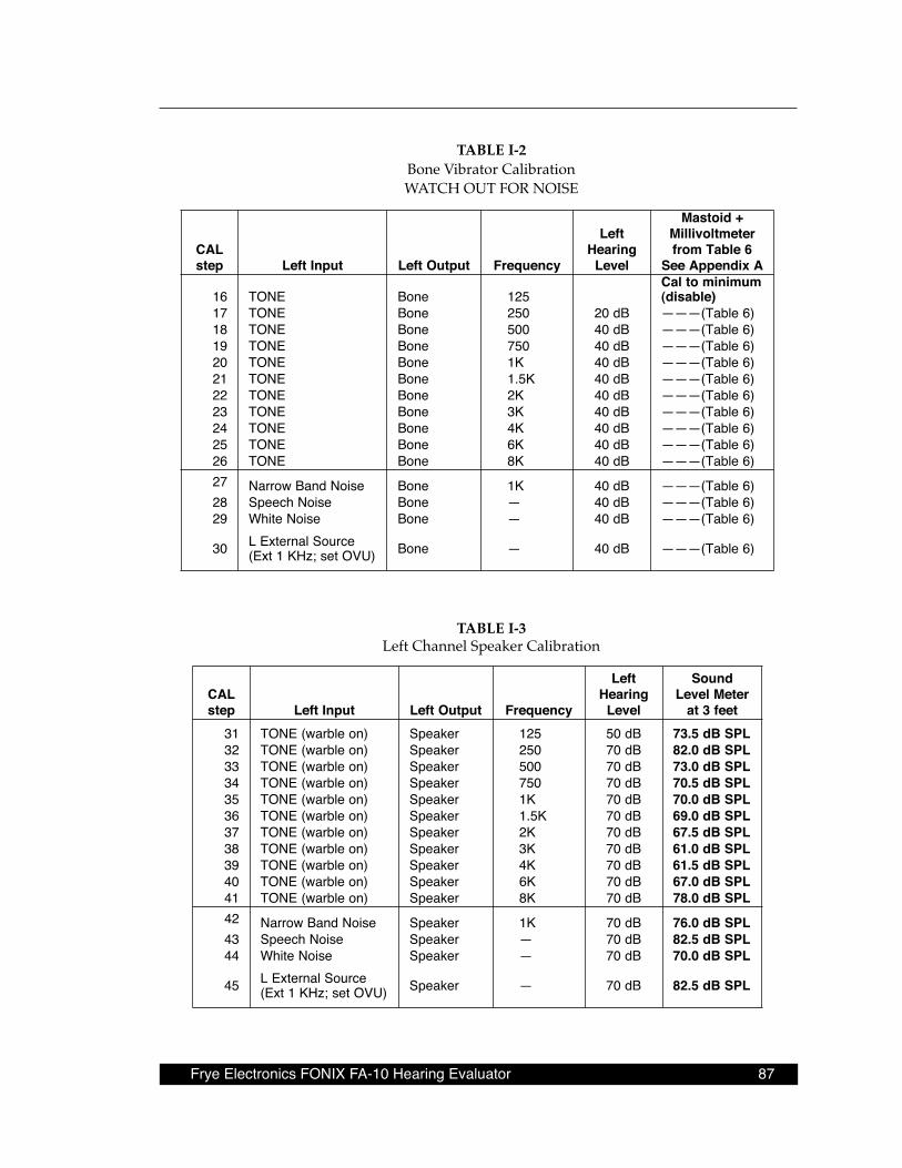
Frye Electronics FONIX FA-10 Hearing Evaluator 87
TABLE I-2 Bone Vibrator Calibration WATCH OUT FOR NOISE
LACpets tupnItfeL tuptuOtfeL ycneuqerF
tfeLgniraeHleveL
+diotsaMretemtlovilliM
6elbaTmorfAxidneppAeeS
61 ENOT enoB 521muminimotlaC
)elbasid(71 ENOT enoB 052 Bd02 )6elbaT(———81 ENOT enoB 005 Bd04 )6elbaT(———91 ENOT enoB 057 Bd04 )6elbaT(———02 ENOT enoB K1 Bd04 )6elbaT(———12 ENOT enoB K5.1 Bd04 )6elbaT(———22 ENOT enoB K2 Bd04 )6elbaT(———32 ENOT enoB K3 Bd04 )6elbaT(———42 ENOT enoB K4 Bd04 )6elbaT(———52 ENOT enoB K6 Bd04 )6elbaT(———62 ENOT enoB K8 Bd04 )6elbaT(———72 esioNdnaBworraN enoB K1 Bd04 )6elbaT(———82 esioNhceepS enoB — Bd04 )6elbaT(———92 esioNetihW enoB — Bd04 )6elbaT(———
03 ecruoSlanretxEL)UVOtes;zHK1txE( enoB — Bd04 )6elbaT(———
TABLE I-3 Left Channel Speaker Calibration
LACpets tupnItfeL tuptuOtfeL ycneuqerF
tfeLgniraeHleveL
dnuoSreteMleveL
teef3ta13 )noelbraw(ENOT rekaepS 521 Bd05 LPSBd5.3723 )noelbraw(ENOT rekaepS 052 Bd07 LPSBd0.2833 )noelbraw(ENOT rekaepS 005 Bd07 LPSBd0.3743 )noelbraw(ENOT rekaepS 057 Bd07 LPSBd5.0753 )noelbraw(ENOT rekaepS K1 Bd07 LPSBd0.0763 )noelbraw(ENOT rekaepS K5.1 Bd07 LPSBd0.9673 )noelbraw(ENOT rekaepS K2 Bd07 LPSBd5.7683 )noelbraw(ENOT rekaepS K3 Bd07 LPSBd0.1693 )noelbraw(ENOT rekaepS K4 Bd07 LPSBd5.1604 )noelbraw(ENOT rekaepS K6 Bd07 LPSBd0.7614 )noelbraw(ENOT rekaepS K8 Bd07 LPSBd0.8724 esioNdnaBworraN rekaepS K1 Bd07 LPSBd0.6734 esioNhceepS rekaepS — Bd07 LPSBd5.2844 esioNetihW rekaepS — Bd07 LPSBd0.07
54 ecruoSlanretxEL)UVOtes;zHK1txE( rekaepS — Bd07 LPSBd5.28
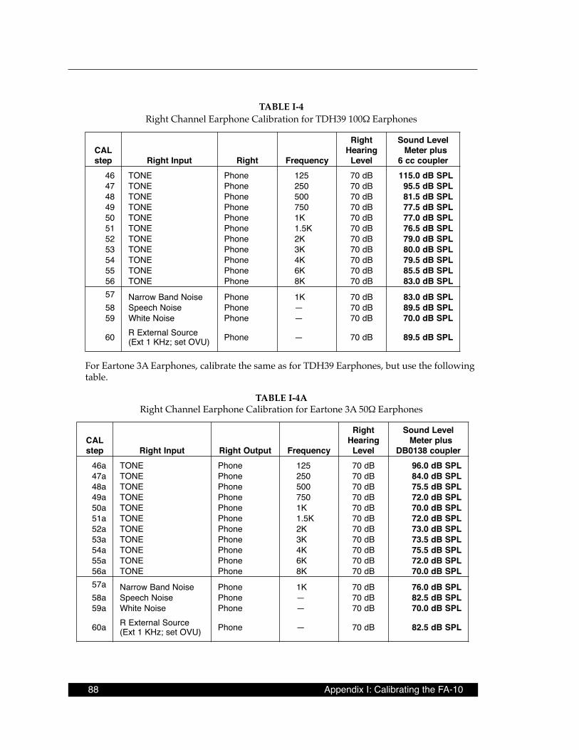
88 Appendix I: Calibrating the FA-10
TABLE I-4 Right Channel Earphone Calibration for TDH39 100Ω Earphones
LACpets tupnIthgiR thgiR ycneuqerF
thgiRgniraeHleveL
leveLdnuoSsulpreteMrelpuoccc6
64 ENOT enohP 521 Bd07 LPSBd0.51174 ENOT enohP 052 Bd07 LPSBd5.5984 ENOT enohP 005 Bd07 LPSBd5.1894 ENOT enohP 057 Bd07 LPSBd5.7705 ENOT enohP K1 Bd07 LPSBd0.7715 ENOT enohP K5.1 Bd07 LPSBd5.6725 ENOT enohP K2 Bd07 LPSBd0.9735 ENOT enohP K3 Bd07 LPSBd0.0845 ENOT enohP K4 Bd07 LPSBd5.9755 ENOT enohP K6 Bd07 LPSBd5.5865 ENOT enohP K8 Bd07 LPSBd0.3875 esioNdnaBworraN enohP K1 Bd07 LPSBd0.3885 esioNhceepS enohP — Bd07 LPSBd5.9895 esioNetihW enohP — Bd07 LPSBd0.07
06 ecruoSlanretxER)UVOtes;zHK1txE( enohP — Bd07 LPSBd5.98
For Eartone 3A Earphones, calibrate the same as for TDH39 Earphones, but use the following table.
TABLE I-4A Right Channel Earphone Calibration for Eartone 3A 50Ω Earphones
LACpets tupnIthgiR tuptuOthgiR ycneuqerF
thgiRgniraeHleveL
leveLdnuoSsulpreteM
relpuoc8310BDa64 ENOT enohP 521 Bd07 LPSBd0.69a74 ENOT enohP 052 Bd07 LPSBd0.48a84 ENOT enohP 005 Bd07 LPSBd5.57a94 ENOT enohP 057 Bd07 LPSBd0.27a05 ENOT enohP K1 Bd07 LPSBd0.07a15 ENOT enohP K5.1 Bd07 LPSBd0.27a25 ENOT enohP K2 Bd07 LPSBd0.37a35 ENOT enohP K3 Bd07 LPSBd5.37a45 ENOT enohP K4 Bd07 LPSBd5.57a55 ENOT enohP K6 Bd07 LPSBd0.27a65 ENOT enohP K8 Bd07 LPSBd0.07a75 esioNdnaBworraN enohP K1 Bd07 LPSBd0.67a85 esioNhceepS enohP — Bd07 LPSBd5.28a95 esioNetihW enohP — Bd07 LPSBd0.07
a06 ecruoSlanretxER)UVOtes;zHK1txE( enohP — Bd07 LPSBd5.28
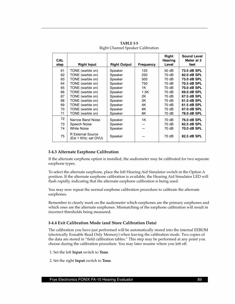
Frye Electronics FONIX FA-10 Hearing Evaluator 89
TABLE I-5 Right Channel Speaker Calibration
LACpets tupnIthgiR tuptuOthgiR ycneuqerF
thgiRgniraeHleveL
leveLdnuoS3tareteM
teef16 )noelbraw(ENOT rekaepS 521 Bd05 LPSBd5.3726 )noelbraw(ENOT rekaepS 052 Bd07 LPSBd0.2836 )noelbraw(ENOT rekaepS 005 Bd07 LPSBd0.3746 )noelbraw(ENOT rekaepS 057 Bd07 LPSBd5.0756 )noelbraw(ENOT rekaepS K1 Bd07 LPSBd0.0766 )noelbraw(ENOT rekaepS K5.1 Bd07 LPSBd0.9676 )noelbraw(ENOT rekaepS K2 Bd07 LPSBd5.7686 )noelbraw(ENOT rekaepS K3 Bd07 LPSBd0.1696 )noelbraw(ENOT rekaepS K4 Bd07 LPSBd5.1607 )noelbraw(ENOT rekaepS K6 Bd07 LPSBd0.7617 )noelbraw(ENOT rekaepS K8 Bd07 LPSBd0.8727 esioNdnaBworraN rekaepS K1 Bd07 LPSBd0.6737 esioNhceepS rekaepS — Bd07 LPSBd5.2847 esioNetihW rekaepS — Bd07 LPSBd0.07
57 ecruoSlanretxER)UVOtes;zHK1txE( rekaepS — Bd07 LPSBd5.28
I-4 .3 Alternate Earphone CalibrationIf the alternate earphone option is installed, the audiometer may be calibrated for two separate earphone types.
To select the alternate earphone, place the left Hearing Aid Simulator switch in the Option A position. If the alternate earphone calibration is available, the Hearing Aid Simulator LED will flash rapidly, indicating that the alternate earphone calibration is being used.
You may now repeat the normal earphone calibration procedure to calibrate the alternate earphones.
Remember to clearly mark on the audiometer which earphones are the primary earphones and which ones are the alternate earphones. Mismatching of the earphone calibration will result in incorrect thresholds being measured.
I-4 .4 Exit Calibration Mode (and Store Calibration Data)The calibration you have just performed will be automatically stored into the internal EEROM (electrically Erasable Read Only Memory) when leaving the calibration mode. Two copies of the data are stored in “field calibration tables.” This step may be performed at any point you choose during the calibration procedure. You may later resume where you left off.
1. Set the left Input switch to Tone.
2. Set the right Input switch to Tone.
90 Appendix I: Calibrating the FA-10
3. Set the right Output switch to Left Channel.
4. Set the left Output switch to Right Channel.
5. Set the left Hearing Aid Simulator switch to HFE.
6. Set the right Hearing Aid Simulator switch to HFE.
7. Press and hold the Pulse and Warble buttons at the same time and hold them down until the Hearing Aid Simulator LEDs go out. This indicates that the calibration data has been stored and you are out of calibration mode. This process will take about 5 seconds.
*** FLASHING RED IS OK ***
Note that the red Level error LEDs will be flashing rapidly because the Output switches are set to an invalid output selection. This is normal. Change the Output switch settings to stop the flashing.
** ERROR ** WARNING ** FLASHING GREEN **
If the calibration did not take because you did not properly set the switch combination to exit the calibration mode or because of FA-10 circuit problems: then the left GREEN Hearing Aid Simulator LED will remain flashing. Recheck the switch combination items 1) through 7) above. If the switch combination is correct, then: sorry! You must repeat the calibration, first replacing U9, the 93C66 EEROM located on the FA-10 CPU/KEYBOARD.
End of procedure. Your FA-10 is now calibrated.
I-5 Other Calibration Options
I-5 .1 How to Discard Calibration ValuesWhile still in the calibration mode, simply turn off the power switch and all calibration infor-mation modifications will be discarded.
I-5 .2 To Enter Calibration Mode with Original Factory CalibrationShould you make a mistake in calibration and want to restore the original factory calibration tables for your FA-10:
1. Turn FA-10 Power switch off.
2. Set the left and right Input switches to Tone. Set the right Output switch to Left Channel. Set the left Output switch to Right Channel. Set the left and right Hearing Aid Simulator switches to Off.
Frye Electronics FONIX FA-10 Hearing Evaluator 91
3. Press and hold down the Output Reverse and Talk Forward buttons.
4. Turn the audiometer rear panel switch ON.
At this point, the FA-10 is in calibration mode. Make any calibration changes necessary, then go to step I-4.4 to save the calibration data and exit calibration.
I-5 .3 To Enter Calibration Mode with an Average of Factory CalibrationsThis is an average of the calibration tables for the first few FA-10s manufactured. These steps will be useful if all of the EEROM tables are defective. Possible uses might include:
• ERROM has been replaced. •Troubleshooting an FA-10 which has multiple electrical problems including a replaced
EEROM (not yet calibrated). • Establishing a “calibration deviation report” for an FA-10 with damaged EEROM calibra-
tion tables. This FA-10 might have been used to collect patient data. (The user operated the FA-10 while the Hearing Aid Simulator green LEDs were flashing in groups of 6 or 7 flashes.)
Unless you know for certain that the data in the EEROM were destroyed by the technician’s calibration errors, the EEROM should be replaced. The cost of the EEROM is small compared to the cost of recalibration.
START:
1. Turn FA-10 Power switch off.
2. Set the left and right Input switches to Tone. Set the right Output switch to Left Channel. Set the left Output switch to Right Channel. Set the left and right Hearing Aid Simulator switches to Off.
3. Press and hold down all 4 of the following buttons: Output Reverse, Pulsed, Warble, Talk Forward. (Use a ruler or pencil.)
4. Turn the FA-10 rear panel POWER switch ON.
At this point, the FA-10 is in calibration mode.
Continue with all the calibration steps and then go to item I-5.4 (following) to save the cali-bration data and exit calibration.

92 Appendix I: Calibrating the FA-10
I-5 .4 Exit Calibration Mode (Store Calibration Data and Store New Factory Calibration Data)Don’t do this unless:
• you have replaced the EEROM, or
• FA-10 transducer(s) have been changed, or else
• you know that the factory calibration tables were destroyed by technician error.
The calibration you have just performed will be automatically stored into the internal EE-ROM (electrically Erasable Read Only Memory) when leaving the calibration mode. This step may be performed at any point you choose during the calibration procedure. You may later resume where you left off.
1. Set the left Input switch to Tone.
2. Set the right Input switch to Tone.
3. Set the right Output switch to Left Channel .
4. Set the left Output switch to Right Channel .
5. Set the left Hearing Aid Simulator switch to HFE.
6. Set the right Hearing Aid Simulator switch to HFE.
7. Press and hold the left Stimulus, right Stimulus, Pulse, and Warble buttons at the same time; and hold them down until the Hearing Aid Simulator LEDs go out. This indicates that the calibration data has been stored and you have exited calibration mode. This pro-cess will take about 10 seconds.
***FLASHING RED IS OK***
Note that the red Level error LEDs will be flashing rapidly because the Output switches are set to an invalid output selection. This is normal. Change the Output switch settings to stop the flashing.
** ERROR ** WARNING ** FLASHING GREEN **
If the calibration did not take because you did not properly set the switch combination to exit the calibration mode or because of FA-10 circuit problems: then the left GREEN Hearing Aid Simulator LED will remain flashing. Recheck the switch combination items 1 through 7 above. If the switch combination is correct, then: sorry! You must repeat the calibration, first replacing U9, the 93C66 EEROM located on the FA-10 CPU/KEYBOARD.
Frye Electronics FONIX FA-10 Hearing Evaluator 93
I-6 EEROM FailuresDuplicate calibration information is stored in the EEROM to insure that the EEROM data is valid. In fact, there are actually five sets of calibration tables in the audiometer. Two are du-plicate factory calibration tables, done by computer through the RS232 port. Another two are duplicate field calibration tables created using the procedures described in this manual. The fifth set of calibration tables is in the EPROM. It is based on average data of the transducers used, and cannot be considered more than approximately correct.
The EEROM, where the calibration information is stored, uses a CRC (cyclical redundancy check) that will detect a failure of the data stored in the EEROM. Three levels of calibration failure are identified by the pattern of the flashing of the Hearing Simulator LEDs.
Should an EEROM failure occur when you turn the audiometer on, turn FA-10 power off, then on again to see if the error will correct itself. If an EEROM error occurs while trying to save the new calibration values just entered, try to exit calibration again. If the error does not go away or is intermittant, replace the EEROM.
Note: See Section I-5.4 if you replace the EEROM.
I-6 .1 Field Calibration Table Bit Error Warning
, OR
The Hearing Aid Simulator LEDs flash in a pattern of one, two, or three times in succession, with pauses between the grouping of flashes.
One of the two field calibration tables contains an error. The other Table is good. The FA-10 is still calibrated but should be serviced. The EEROM is less than perfect.
This type of error can often be corrected by recalibrating the audiometer as described above, BUT DO NOT. Order a new EEROM from Frye Electronics, because the cost of this part is small compared to the usual cost of calibration.
I-6 .2 Both Field Calibration Tables Bit Error Warning
OR
The Hearing Aid Simulator LEDS flash in groups of 4 or 5 flashes. In addition, Hearing Level and Frequency LEDS will flash every three seconds.
Both field calibration tables have failed. The FA-10 is now using one of the two factory cali-bration tables. If the factory calibration is still valid, then the FA-10 is still calibrated, but ser-vicing is recommended. If the factory calibration is not valid because of a transducer change, or because the sound field was calibrated in the field, then the FA-10 should be considered out of calibration.
A serious multiple failure has occurred inside the EEROM. You might succeed in doing a field calibration, BUT DO NOT. Replace the EEROM.

94 Appendix I: Calibrating the FA-10
I-6 .3 Total EEROM Failure Warning
OR
The third level of failure is complete EEROM failure signaled by a flashing pattern of six or seven on the Hearing Simulator LEDs. Hearing Level and Frequency LEDs will flash faster (once per second) than for an EEROM error. In this case, the audiometer will default to the backup calibration burned into the EPROM. This calibration is based on average values and is not precise.
If the user insists on taking data with this warning present, data can be salvaged by provid-ing a table of calibration data from before calibration and from after calibration.
I-6 .4 Calibration Failure / Fail-Safe Shutdown THEN
Should all five sets of calibration tables fail, the audiometer will go into fail-safe mode and shut down all operation. If you see the Hearing Simulator LEDs flash a count of seven fol-lowed by a flash count of five, you know that the back-up calibration in the EPROM has failed.
I-6 .5 Recovery from a Fail-Safe ErrorA shutdown is a very rare occurrence. It is possible that a shutdown will be due to a transient failure such as a static discharge or power surge. In such cases, the problem can normally be cured by turning the instrument off and then back on again. A problem caused by hardware failure will require the instrument to be repaired.
An inadvertent loss of calibration due to technician error can normally be cured by recalibrat-ing the instrument. The EEROM can be calibrated over 10,000 times, so that should not be a cause of concern.
I-7 Procedure to Establish Artificial Mastoid Calibration TableThis procedure is to be done each time the artificial mastoid is sent to a certification labora-tory. It is NOT done for each audiometer. Keep the completed TABLE I-6 in a safe place for reference.
Information Required
1. Artificial mastoid sensitivity at 1000 Hz measured in nanovolts per micronewton (nV/µN). If you have sensitivity in nanovolts per dyne, divide by 10 to get nanovolts per micronewton. 1 microvolt = 1000 nanovolts.
2. A graph or table showing the artificial mastoid output at frequencies from 250 Hz to 6000 Hz; in dB relative to 1000 Hz.
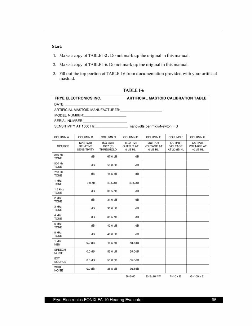
Frye Electronics FONIX FA-10 Hearing Evaluator 95
Start:
1. Make a copy of TABLE I-2 . Do not mark up the original in this manual.
2. Make a copy of TABLE I-6. Do not mark up the original in this manual.
3. Fill out the top portion of TABLE I-6 from documentation provided with your artificial mastoid.
TABLE I-6ELBATNOITARBILACDIOTSAMLAICIFITRA.CNISCINORTCELEEYRF
____________________________:ETAD
LEDOM______________________:RERUTCAFUNAMDIOTSAMLAICIFITRA
:REBMUN_____________________________________________
:REBMUNLAIRESS=notweNorcimrepstlovonan_________________:zH0001TAYTIVITISNES
ECRUOSDIOTSAMEVITALER
YTIVITISNES
6657OSI)E(7891
DLOHSERHT
EVITALERTATUPTUO
LHBd0
TUPTUOTAEGATLOV
LHBd0
TUPTUOEGATLOV
LHBd02TA
TUPTUOTAEGATLOV
LHBd04
zH052ENOT Bd Bd0.76 Bd
zH005ENOT Bd Bd0.85 Bd
zH057ENOT Bd Bd5.84 Bd
zHk1ENOT
zHk5.1ENOT Bd Bd5.63 Bd
zHk2ENOT Bd Bd0.13 Bd
zHk3ENOT Bd Bd0.03 Bd
zHk4ENOT Bd Bd5.53 Bd
zHk6ENOT Bd Bd0.04 Bd
zHk8ENOT Bd Bd0.04 Bd
zHk1NBN Bd0.0 Bd5.84 Bd5.84
HCEEPSESION Bd0.0 Bd0.55 Bd0.55
TXEECRUOS Bd0.0 Bd0.55 Bd0.55
ETIHWESION Bd0.0 Bd5.63 Bd5.63
C+B=D 01xS=E )02/D(
COLUMN A COLUMN B COLUMN C COLUMN D COLUMN E COLUMN F COLUMN G
G=100 x EF=10 x E
0.0 dB 42.5 dB 42.5 dB
96 Appendix I: Calibrating the FA-10
4. From the table or graph provided with your artificial mastoid, enter the relative sensitiv-ity of your artificial mastoid at 8 frequencies. 1 KHz must be 0 dB. The numbers must be in dB. If the frequency has less output than 1 KHz, then the relative output has a minus (-) sign.
5. Add the numbers in COLUMN B plus the numbers in COLUMN C and write the totals in COLUMN D
6. Using a scientific calculator, for each number in COLUMN D:
• Divide number by 20 • Press 10^x key (raise 10 to the above result) • Multiply by S (the sensitivity of your artificial mastoid at 1000 Hz) • Write the result in COLUMN E including voltage label (nV, µV, mV, V). Note: The result must have at least 3 significant digits. Change to microvolts or millivolts
when required.
7. Multiply each number in COLUMN E by 10 and write the result in COLUMN F includ-ing voltage label (nV, µV, mV, V).
8. Multiply each number in COLUMN E by 100 and write the result in COLUMN G includ-ing voltage label (nV, µV, mV, V).
9. Enter the appropriate values in TABLE I-2.
End of procedure
Note: If you wish to calculate voltages 10 dB higher, multiply by the square root of 10. 2√10 = 3.1623.