for ancillary equipment for low velocity air drop …system-heavy (epjs-h) nsn 1670-01-544-7425. 3....
TRANSCRIPT

*ARMY TM 10-1670-296-20&P AIR FORCE T.O. 13C7-49-2
DISTRIBUTION STATEMENT A: Approved for public release; distribution is unlimited. *This manual supercedes TM 10-1670-296-20&P, dated 15 September 1995 HEADQUARTERS, DEPARTMENTS OF THE ARMY AND AIR FORCE 30 OCTOBER 2002
Change 2
TECHNICAL MANUAL
UNIT MAINTENANCE MANUAL (INCLUDING REPAIR PARTS AND SPECIAL TOOLS LIST)
FOR ANCILLARY EQUIPMENT FOR
LOW VELOCITY AIR DROP SYSTEM (LVADS)
Line, Multi-Loop (Extraction Lines, Deployment Lines, Bag Clustering Lines, Riser Extension, Suspension Slings): NSNs 1670-01-062-6301; 1670-01-062-6306; 1670-01-062-6304; 1670-01-062-6305; 1670-01-062-6311; 1670-01-063-7760; 1670-01-062-6310; 1670-01-062-6303; 1670-01-062-6307; 1670-01-062-6312 1670-01-063-7761; 1670-01-062-6308; 1670-01-062-6302; 1670-01-064-4453; 1670-01-107-7651 1670-01-062-6309; 1670-01-064-4451; 1670-01-064-4452; 1670-01-107-7652; Coupling, Extraction Force Transfer: NSNs 1670-00-434-5783; 1670-00-434-5785; 1670-00-434-5787; 1670-00-434-5782; 1670-01-326-7309; Release, Cargo Parachute, M-1: NSN 1670-01-097-8816; Release, Cargo Parachute, M-2: NSN 1670-01-097-8817; Link Assembly, Single Suspension, Type IV: NSN 1670-00-783-5988; Assembly, Heavy Duty: NSNs Link, 4-Point 1670-00-006-2752; Cover, Link, Type IV 1670-00-360-0329; Clevis, Aerial Delivery: NSNs 4030-00-360-0304; 4030-00-678-8562; 4030-00-090-5354; 4030-00-432-2516; Cover, Clevis: NSN 1670-00-360-0328; Strap, Parachute Release, Single Knife: NSN 1670-01-207-7223; Strap, Parachute Release, Multi-Knife: NSN 4340-00-040-8219 ; Link Assembly, Coupling, 3-Point: NSN 1670-01-307-0155; Bracket, Suspension: NSN 1670-01-207-7223; Bracket, Suspension: NSN 1670-00-078-4319; Plate, Suspension: NSN 1670-01-141-1522; Tie-down, Cargo, 10K: NSN 1670-00-937-0271; Tie-down, Cargo, Quick-Release: NSN 1670-01-333-6082; Tie-down, Cargo, Aircraft: NSN 1670-00-545-9063; Drive Off Aid, Type IV: NSN 1670-01-344-0825; Link, 2-Point, 3 ¾-IN.: NSN 1670-01-493-6418; Link, 2-Point, 5 ½-IN.: NSN 1670-01-493-6420; Break Away Static Line, Main: NSN 1670-01-487-5461; Jettison System, Parachute, Extraction: NSN 1670-01-475-1990; Link, Parachute Connector: NSN 1670-01-483-8259; Jettison Device, Parachute Extraction, Heavy: NSN 1670-01-544-7425


TM 10-1670-296-20&P
a Change 2
WARNING SUMMARY
This warning summary contains general safety warnings and hazardous material warnings that must be understood and applied during operation and maintenance of this equipment. Failure to observe these precautions could result in serious injury or death to personnel.
WARNING
Personnel performing instructions involving operations, procedures, and practices that are included or implied in this technical manual will observe the following instructions. Disregard of these instructions can result in serious injury or death.
WARNING
FIRST AID
For artificial respiration, refer to FM 4-25.11.
WARNING
The squib has a 5-year shelf life assuming it remains in the approved packaging. Once brought into the service, its storage life is 1 year. Failure to follow storage conditions can result in injury to personnel.
WARNING Squib must be installed with squib cable and safety cap installed. DO NOT SEPARATE SQUIB CABLE WITH SAFETY CAP FROM SQUIB. Failure to follow precautions can result in injury to personnel.

TM 10-1670-296-20&P
Change 2 b
WARNING After the squib has been installed in the EPJD, handle EPJD from the bottom only. Failure to do so can result in injury to personnel.
WARNING
The squib is a pyrotechnic device. The squib must be handled and installed with the squib cable and safety cap attached. DO NOT SEPARATE SQUIB CABLE WITH SAFETY CAP FROM THE SQUIB UNLESS INSTRUCTED BY THIS TECHNICAL MANUAL. Use care when handling the live squib to prevent accidental firing of the device. Avoid dropping or jarring the squib and avoid static electricity. Failure to follow precautions can result in serious burn or eye injury to personnel.
WARNING
Wear safety goggles and hand protection when handling the squib
WARNING
Defective, unsatisfactory or expired, unfired squibs must be repackaged in original packing material including the OEM shorting clip. Install shorting clip in squib BEFORE removing from EPJD. Disposal of defective, unsatisfactory, or expired unfired squib MUST ONLY be through the local Explosive Ordinance Disposal unit accompanied by the Material Safety Data Sheet (MSDS).
WARNING
Ensure that the safety pin is locking the cutter blade into the cutter block of the EPJD-H before the squib is installed. Ensure knife blade is pointed in a safe direction. After the squib has been installed, only handle the EPJD-H from the bottom. Failure to do so can result in serious hand injury to personnel.
WARNING
Trapped gases. When removing a fired squib, there may be residual gases trapped inside the cutter block. Back the squib out of the cutter block slowly to allow any gases built up inside the cylinder to escape at a controlled rate.

ARMY TM 10-1670-296-20&P AIR FORCE T.O. 13C7-49-2
HEADQUARTERS,
CHANGE DEPARTMENTS OF THE ARMY AND THE AIR FORCE NO.2 WASHINGTON, D.C., 8 February 2008
TECHNICAL MANUAL
UNIT MAINTENANCE MANUAL
(INCLUDING REPAIR PARTS AND SPECIAL TOOLS LIST) FOR
ANCILLARY EQUIPMENT FOR LOW VELOCITY AIR DROP SYSTEM (LVADS) LINE, MULTI-LOOP (EXTRACTION LINES, DEPLOYMENT LINES, BAG CLUSTERING LINES, RISER EXTENSION, SUSPENSION SLINGS): NSNS 1670-01-062-6301; 1670-01-062-6306; 1670-01-062-6304; 1670-01-062-6305; 1670-01-062-6311; 1670-01-063-7760; 1670-01-062-6310; 1670-01-062-6303; 1670-01-062-6307; 1670-01-062-6312 1670-01-063-7761; 1670-01-062-6308; 1670-01-062-6302; 1670-01-064-4453; 1670-01-107-7651 1670-01-062-6309; 1670-01-064-4451; 1670-01-064-4452; 1670-01-107-7652; COUPLING, EXTRACTION FORCE TRANSFER: NSNS 1670-00-434-5783; 1670-00-434-5785; 1670-00-434-5787; 1670-00-434-5782; 1670-01-326-7309; RELEASE, CARGO PARACHUTE, M-1: NSN 1670-01-097-8816; RELEASE, CARGO PARACHUTE, M-2: NSN 1670-01-097-8817; LINK ASSEMBLY, SINGLE SUSPENSION, TYPE IV: NSN 1670-00-783-5988; ASSEMBLY, HEAVY DUTY: NSN LINK, 4-POINT 1670-00-006-2752; COVER, LINK, TYPE IV 1670-00-360-0329; CLEVIS, AERIAL DELIVERY: NSNS 4030-00-360-0304; 4030-00-678-8562; 4030-00-090-5354; 4030-00-432-2516; COVER, CLEVIS: NSN 1670-00-360-0328; STRAP, PARACHUTE RELEASE, SINGLE KNIFE: NSN 1670-00-998-0116; STRAP, PARACHUTE RELEASE, MULTI-KNIFE: NSN 5340-00-040-8219; LINK ASSEMBLY, COUPLING, 3-POINT: NSN 1670-01-307-0155; BRACKET, SUSPENSION: NSN 1670-01-207-7223; BRACKET, SUSPENSION: NSN 1670-00-078-4319; PLATE, SUSPENSION: NSN 1670-01-141-1522; TIE-DOWN, CARGO, 10K: NSN 1670-00-937-0271; TIE-DOWN, CARGO, QUICK-RELEASE: NSN 1670-01-333-6082; TIE-DOWN, CARGO, AIRCRAFT: NSN 1670-00-212-1150; DRIVE OFF AID, TYPE IV: NSN 1670-01-344-0825; LINK, 2-POINT, 3 ¾-IN.: NSN 1670-01-493-6418; LINK, 2-POINT, 5 ½-IN.: NSN 1670-01-493-6420; BREAK AWAY STATIC LINE, MAIN: NSN 1670-01-487-5461; JETTISON SYSTEM, PARACHUTE, EXTRACTION: NSN 1670-01-475-1990; LINK, PARACHUTE CONNECTOR: NSN 1670-01483-8259; JETTISON DEVICE, PARACHUTE EXTRACTION, HEAVY: NSN 1670-01-544-7425 DISTRIBUTION STATEMENT A. - Approved for public release; distribution is unlimited. TM 10-1670-296-20&P, 30 October 2002, is updated as follows: 1. File this sheet in front of the manual for reference. 2. This change is a result of new unit maintenance procedures for the Extraction Parachute Jettison
System-Heavy (EPJS-H) NSN 1670-01-544-7425. 3. New or updated change information is indicated by a vertical bar in the outer margin of the page. 4. Added illustrations are indicated by a vertical bar adjacent to the figure number. Changed illustrations
are indicated by a vertical bar adjacent to the changed material and adjacent to the figure number. 5. Remove old pages and insert new pages as indicated below:
Remove Pages Insert Pages Cover Cover a-b a-b A-B A/(B Blank) i-iv i-v/(vi Blank) Index 1-6 2020 Instructions
Index 1-6 2028 Instructions
Sample 2028 Front/Back Sample 2028 Front/Back 2028 Front/Back 2028 Front/Back 2028 Front/Back 2028 Front/Back

ARMY TM 10-1670-296-20&P AIR FORCE T.O. 13C7-49-2
6. Replace the following work packages with their revised version:
Work Package
Work Package
Work Package
Work Package
WP 0001 00 WP 0044 01 WP 0106 00 WP 0124 00 WP 0002 00 WP 0059 00 WP 0110 00 WP 0125 00 WP 0005 00 WP 0064 00 WP 0115 00 WP 0006 00 WP 0099 00 WP 0122 00 WP 0044 00 WP 0100 00 WP 0123 00
7. Add the following work packages:
Work Package
Work Package
Work Package
Work Package
WP 0100 01 WP 0106 01
C-02 By Order of the Secretary of the Army:
GEORGE W. CASEY, JR. General, United States Army Chief of Staff
Official: JOYCE E. MORROW Administrative Assistant to the Secretary of the Army 0803102 DISTRIBUTION: To be distributed in accordance with initial distribution number (IDN) 256283 requirements for TM 10-1670-296-20&P.
ARMY TM 10-1670-296-20&P AIR FORCE T.O. 13C7-49-2
HEADQUARTERS
CHANGE DEPARTMENTS OF THE ARMY AND THE AIR FORCE NO.1 WASHINGTON, D.C., 31 MARCH 2006
TECHNICAL MANUAL
UNIT MAINTENANCE MANUAL
(INCLUDING REPAIR PARTS AND SPECIAL TOOLS LIST) FOR
ANCILLARY EQUIPMENT FOR LOW VELOCITY AIR DROP SYSTEM (LVADS) LINE, MULTI-LOOP (EXTRACTION LINES, DEPLOYMENT LINES, BAG CLUSTERING LINES, RISER EXTENSION, SUSPENSION SLINGS): NSNS 1670-01-062-6301; 1670-01-062-6306; 1670-01-062-6304; 1670-01-062-6305; 1670-01-062-6311; 1670-01-063-7760; 1670-01-062-6310; 1670-01-062-6303; 1670-01-062-6307; 1670-01-062-6312 1670-01-063-7761; 1670-01-062-6308; 1670-01-062-6302; 1670-01-064-4453; 1670-01-107-7651 1670-01-062-6309; 1670-01-064-4451; 1670-01-064-4452; 1670-01-107-7652; COUPLING, EXTRACTION FORCE TRANSFER: NSNS 1670-00-434-5783; 1670-00-434-5785; 1670-00-434-5787; 1670-00-434-5782; 1670-01-326-7309; RELEASE, CARGO PARACHUTE, M-1: NSN 1670-01-097-8816; RELEASE, CARGO PARACHUTE, M-2: NSN 1670-01-097-8817; LINK ASSEMBLY, SINGLE SUSPENSION, TYPE IV: NSN 1670-00-783-5988; ASSEMBLY, HEAVY DUTY: NSNS LINK, 4-POINT 1670-00-006-2752; COVER, LINK, TYPE IV 1670-00-360-0329; CLEVIS, AERIAL DELIVERY: NSNS 4030-00-360-0304; 4030-00-678-8562; 4030-00-090-5354; 4030-00-432-2516; COVER, CLEVIS: NSN 1670-00-360-0328; STRAP, PARACHUTE RELEASE, SINGLE KNIFE: NSN 1670-01-207-7223; STRAP, PARACHUTE RELEASE, MULTI-KNIFE: NSN 4340-00-040-8219 ; LINK ASSEMBLY, COUPLING, 3-POINT: NSN 1670-01-307-0155; BRACKET, SUSPENSION: NSN 1670-01-207-7223; BRACKET, SUSPENSION: NSN 1670-00-078-4319; PLATE, SUSPENSION: NSN 1670-01-141-1522; TIE-DOWN, CARGO, 10K: NSN 1670-00-937-0271; TIE-DOWN, CARGO, QUICK-RELEASE: NSN 1670-01-333-6082; TIE-DOWN, CARGO, AIRCRAFT: NSN 1670-00-545-9063; DRIVE OFF AID, TYPE IV: NSN 1670-01-344-0825; LINK, 2-POINT, 3 ¾-IN.: NSN 1670-01-493-6418; LINK, 2-POINT, 5 ½-IN.: NSN 1670-01-493-6420; BREAK AWAY STATIC LINE, MAIN: NSN 1670-01-487-5461; JETTISON SYSTEM, PARACHUTE, EXTRACTION: NSN 1670-01-475-1990; LINK, PARACHUTE CONNECTOR: NSN 1670-01483-8259 DISTRIBUTION STATEMENT A. - Approved for public release; distribution is unlimited. TM 10-1670-296-20&P, 30 October 2002, is updated as follows: 1. File this sheet in front of the manual for reference. 2. This change implements changes in unit maintenance procedures for the Squib, Squib Cable and
EPJD for the Extraction Parachute Jettison System (EPJS) NSN 1670-01-475-1990. The Parachute Connector Link NSN 1670-01483-8259 has also been added.
3. New or updated change information is indicated by a vertical bar in the outer margin of the page. 4. Added illustrations are indicated by a vertical bar adjacent to the figure number. Changed illustrations
are indicated by a vertical bar adjacent to the changed material and adjacent to the figure number. 5. Remove old pages and insert new pages as indicated below:
Remove Pages Insert Pages a/b a/b A/(B Blank) A/B i-iv i-iv Index 1-6 Index 1-6 Sample 2028 Front/Envelope Sample 2028 Front/Back 2028 Front/Envelope 2028 Front/Back 2028 Front/Back 2028 Front/Back

ARMY TM 10-1670-296-20&P AIR FORCE T.O. 13C7-49-2
6. Replace the following work packages with their revised version:
Work Package
Work Package
Work Package
Work Package
WP 0002 00 WP 0044 00 WP 0110 00 WP 0123 00 WP 0005 00 WP 0064 00 WP 0115 00 WP 0124 00 WP 0006 00 WP 0099 00 WP 0120 01
By Order of the Secretaries of the Army and Air Force: C1
PETER J. SCHOOMAKER General, United States Army
Chief of Staff Official: JOYCE E. MORROW Administrative Assistant to the Secretary of the Army 0607514
JOHN P. JUMPER
General, USAF Chief of Staff
GREGORY S. MARTIN General, USAF
Commander, AFMC DISTRIBUTION: To be distributed in accordance with initial distribution number (IDN) 256283 requirements for TM 10-1670-296-20&P.

TM 10-1670-296-20&P
INSERT LATEST UPDATED PAGES / WORK PACKAGES. DESTROY SUPERSEDED DATA.
A/(B Blank) Change 2 USA
LIST OF EFFECTIVE PAGES/WORK PACKAGES NOTE: The portion of text affected by the changes is indicated by a vertical line in the outer margins of the
page. Changes to illustrations are indicated by a vertical bar adjacent to the title. Change to wiring diagrams are indicated by shaded areas.
Dates of issue for the original manual and changed pages/work packages are:
Original 30 October 2002 Change 1 Change 2
31 March 2006 8 February 2008
TOTAL NUMBER OF PAGES FOR FRONT AND REAR MATTER IS 32. THE TOTAL NUMBER OF WORK PACKAGES IS 131, CONSISTING OF THE FOLLOWING:
Page/WP No. Change No. Page/WP No. Change No. Cover 2 a – b 2 i – vi 2 Chapter titles 0 WP 0001 00 – 0002 00 2 WP 0003 00 – 0004 00 0 WP 0005 00 – 0006 00 2 WP 0007 00 – 0043 00 0 WP 0044 00 – 0044 01 2 WP 0045 00 – 0058 00 0 WP 0059 00 2 WP 0060 00 – 0063 00 0 WP 0064 00 2 WP 0065 00 – 0098 00 0 WP 0099 00 – 0100 01 2 WP 0101 00 – 0105 00 0 WP 0106 00 – 0106 01 2 WP 0107 00 – 0109 00 0 WP 0110 00 2 WP 0111 00 – 0114 00 0 WP 0115 00 2 WP 0116 00 – 0120 00 0 WP 0120 01 1 WP 0121 00 0 WP 0122 00 – 0125 00 2 WP 0126 00 – 0127 00 0 Index 2


TM 10-1670-296-20&P AIR FORCE T.O. 13C7-49-2
i Change 2
HEADQUATERS, DEPARTMENTS OF THE ARMY AND THE AIR FORCE
WASHINGTON, D.C., 30 OCTOBER 2002
TECHNICAL MANUAL UNIT MAINTENANCE MANUAL
(INCLUDING REPAIR PARTS AND SPECIAL TOOLS LIST) FOR
ANCILLARY EQUIPMENT FOR LOW VELOCITY AIR DROP SYSTEMS (LVADS)
Line, Multi-Loop (Extraction Lines, Deployment Lines, Bag Clustering Lines, Riser Extension, Suspension Slings): NSNs 1670-01-062-6301; 1670-01-062-6306; 1670-01-062-6304; 1670-01-062-6305; 1670-01-062-6311; 1670-01-063-7760; 1670-01-062-6310; 1670-01-062-6303; 1670-01-062-6307; 1670-01-062-6312 1670-01-063-7761; 1670-01-062-6308; 1670-01-062-6302; 1670-01-064-4453; 1670-01-107-7651 1670-01-062-6309; 1670-01-064-4451; 1670-01-064-4452; 1670-01-107-7652; Coupling, Extraction Force Transfer: NSNs 1670-00-434-5783; 1670-00-434-5785; 1670-00-434-5787; 1670-00-434-5782; 1670-01-326-7309; Release, Cargo Parachute, M-1: NSN 1670-01-097-8816; Release, Cargo Parachute, M-2: NSN 1670-01-097-8817; Link Assembly, Single Suspension, Type IV: NSN 1670-00-783-5988; Assembly, Heavy Duty: NSNs Link, 4-Point 1670-00-006-2752; Cover, Link, Type IV 1670-00-360-0329; Clevis, Aerial Delivery: NSNs 4030-00-360-0304; 4030-00-678-8562; 4030-00-090-5354; 4030-00-432-2516; Cover, Clevis: NSN 1670-00-360-0328; Strap, Parachute Release, Single Knife: NSN 1670-01-207-7223; Strap, Parachute Release, Multi-Knife: NSN 4340-00-040-8219 ; Link Assembly, Coupling, 3-Point: NSN 1670-01-307-0155; Bracket, Suspension: NSN 1670-01-207-7223; Bracket, Suspension: NSN 1670-00-078-4319; Plate, Suspension: NSN 1670-01-141-1522; Tie-down, Cargo, 10K: NSN 1670-00-937-0271; Tie-down, Cargo, Quick-Release: NSN 1670-01-333-6082; Tie-down, Cargo, Aircraft: NSN 1670-00-545-9063; Drive Off Aid, Type IV: NSN 1670-01-344-0825; Link, 2-Point, 3 ¾-IN.: NSN 1670-01-493-6418; Link, 2-Point, 5 ½-IN.: NSN 1670-01-493-6420; Break Away Static Line, Main: NSN 1670-01-487-5461; Jettison System, Parachute, Extraction: NSN 1670-01-475-1990; Link, Parachute Connector: NSN 1670-01-483-8259; Jettison Device, Parachute Extraction-Heavy: NSN1670-01-544-7425
REPORTING ERRORS AND RECOMMENDING IMPROVEMENTS
ARMY You can help improve this manual. If you find any mistakes or if you know of a way to improve the procedures, please let us know. Mail you letter or DA Form 2028 (Recommended Changes to Publications and Blank Forms) directly to: Commander, U.S. Army Tank-automotive and Armament Command, ATTN: AMSTA-LC-SECT, Kansas St., Natick, MA 01760. You may also send in your recommended changes via electronic mail or by fax. Our fax number is (DSN 256-5205 and Commercial number 508-233-5205). Our email address is [email protected].
AIR FORCE Reports by U.S. Air Force units should be submitted on AFTO Form 22 (Technical Order Publication Improvement Report and Reply) and forwarded to the address prescribed above for the Army. An information copy of the prepared AFTO Form 22 shall be furnished to WP-ALC/TILTA, 420 2nd Street, Suite 100, Robins AFB, GA 31098-1640.
DISTRIBUTION STATEMENT A: Approved for public release; distribution is unlimited. __________________________________________________________________________________________________________________________________________________________________________________________________________________________________ *This manual supercedes TM 10-1670-296-20&P, dated 15 September 1995

TM 10-1670-296-20&P
Change 2 ii
TABLE OF CONTENTS
WP Sequence No.
WARNING SUMMARY A
HOW TO USE THIS MANUAL V
CHAPTER 1 – INTRODUCTORY INFORMATION General Information .............................................................................................................................. 0001 00 Equipment Description and Data .......................................................................................................... 0002 00
CHAPTER 2 – OPERATOR MAINTENANCE INSTRUCTIONS
Service Upon Receipt ........................................................................................................................... 0003 00 Preventive Maintenance Checks and Services (PMCS), Introduction .................................................. 0004 00 Preventive Maintenance Checks and Services (PMCS), Before Procedures ....................................... 0005 00 Preventive Maintenance Checks and Services (PMCS), After Procedures .......................................... 0006 00
CHAPTER 3 – UNIT MAINTENANCE INSTRUCTIONS
Inspection .............................................................................................................................................. 0007 00 Cleaning and Drying ............................................................................................................................. 0008 00 Salt/Fresh-Water Contamination Test ................................................................................................... 0009 00 Sewing Procedures ............................................................................................................................... 0010 00 Marking, Restencilling, and Repainting ................................................................................................ 0011 00 Multi-Loop ............................................................................................................................................. 0012 00 Extraction Force Transfer Coupling ...................................................................................................... 0013 00 EFTC Adapter Link Assembly ............................................................................................................... 0014 00 EFTC 3-Point Adapter Link Assembly .................................................................................................. 0015 00 EFTC Connector Latch Assembly ......................................................................................................... 0016 00 EFTC Latch Assembly Coupling ........................................................................................................... 0017 00 EFTC Cable Assembly .......................................................................................................................... 0018 00 EFTC Actuator Assembly ...................................................................................................................... 0019 00 M-1 Cargo Parachute Release ............................................................................................................. 0020 00 M-2 Cargo Parachute Release ............................................................................................................. 0021 00 Parachute Connector ............................................................................................................................ 0022 00 Timer Delay Assembly .......................................................................................................................... 0023 00 Type IV Single Suspension Link Assembly .......................................................................................... 0024 00 Heavy-Duty Link Assembly ................................................................................................................... 0025 00 4-Point Link ........................................................................................................................................... 0026 00 Type IV Link Cover ............................................................................................................................... 0027 00 Aerial Delivery Clevis ............................................................................................................................ 0028 00 Clevis Cover .......................................................................................................................................... 0029 00 Single Knife Parachute Release Strap ................................................................................................. 0030 00 Multi-Knife Parachute Release Strap .................................................................................................... 0031 00 3-Point Coupling Link Assembly ........................................................................................................... 0032 00 M-35 Suspension Bracket ..................................................................................................................... 0033 00 M-59 Suspension Bracket ..................................................................................................................... 0034 00

TM 10-1670-296-20&P
iii Change 2
CHAPTER 3 – UNIT MAINTENANCE INSTRUCTIONS- continued
Suspension Plate .................................................................................................................................. 0035 00 10K Cargo Tie-Down ............................................................................................................................ 0036 00 Quick-Release Cargo Tie-Down ........................................................................................................... 0037 00 Type IV Drive-Off Aid ............................................................................................................................ 0038 00 Aircraft Cargo Tie-Down ....................................................................................................................... 0039 00 3 ¾-IN., 2-Point Link ............................................................................................................................. 0040 00 5 ½-IN., 2-Point Link ............................................................................................................................. 0041 00 Release Away Static Line Assembly .................................................................................................... 0042 00 Extraction Parachute Jettison System (EPJS) ...................................................................................... 0043 00 Extraction Parachute Jettison Device (EPJD), Squib, and Squib Cable ............................................... 0044 00 Extraction Parachute Jettison Device (EPJD-H), Squib, and Squib Cable ........................................... 0044 01 Y-Connector .......................................................................................................................................... 0045 00 Y-Connector Mounting Box (C-130, C-141, C-17, C-5) ........................................................................ 0046 00 Control Box ........................................................................................................................................... 0047 00 Platform Cable (All)/4-Foot Extension Cable (C-5 and C-17 only) ....................................................... 0048 00 10-Foot Interconnect Cable .................................................................................................................. 0049 00 50-Foot Main Cable .............................................................................................................................. 0050 00 20-Foot Power Cable ............................................................................................................................ 0051 00 Protective Cover ................................................................................................................................... 0052 00 Kit Bag .................................................................................................................................................. 0053 00 Y-Connector Mounting Box Tie-Down Bracket (C-5) ............................................................................ 0054 00 20-Foot Power Cable Extension (C-17 only) ........................................................................................ 0055 00 1-Foot Power Cable Adapter (C-5 only) ................................................................................................ 0056 00 Safety Cap ............................................................................................................................................ 0057 00 Initiator Simulator .................................................................................................................................. 0058 00 Squib Tester .......................................................................................................................................... 0059 00 28 VDC Power Supply .......................................................................................................................... 0060 00
CHAPTER 4 – SUPPORTING INFORMATION
Preparation For Storage ....................................................................................................................... 0061 00 Preparation For Shipment ..................................................................................................................... 0062 00 References ............................................................................................................................................ 0063 00 Maintenance Allocation Chart (MAC) ................................................................................................... 0064 00 Repair Parts and Special Tools List (RPSTL), Introduction .................................................................. 0065 00 RPSTL Group 01 Multi-Loop Line ......................................................................................................... 0066 00 RPSTL Group 02 Extraction Force Transfer Coupling ......................................................................... 0067 00 RPSTL Group 0201 Extraction Force Transfer Coupling Adapter Link Assembly ................................ 0068 00 RPSTL Group 0202 Extraction Force Transfer Coupling 3-Point Coupling Link Assembly .................. 0069 00 RPSTL Group 0203 Extraction Force Transfer Coupling Latch Assembly Coupling ............................ 0070 00 RPSTL Group 0204 Connector Latch Assembly .................................................................................. 0071 00 RPSTL Group 0205 Coupling Cable Assembly .................................................................................... 0072 00 RPSTL Group 0206 Actuator Assembly ............................................................................................... 0073 00 RPSTL Group 03 M-1 Cargo Parachute Release ................................................................................. 0074 00 RPSTL Group 0301 Parachute Connector ........................................................................................... 0075 00 RPSTL Group 0302 Timer Delay Assembly ......................................................................................... 0076 00 RPSTL Group 04 M-2 Cargo Parachute Release ................................................................................. 0077 00 RPSTL Group 0401 Parachute Connector ........................................................................................... 0078 00 RPSTL Group 0402 Timer Delay Assembly ......................................................................................... 0079 00 RPSTL Group 05 Type IV Single Suspension Link Assembly .............................................................. 0080 00 RPSTL Group 0501 Heavy-Duty Link Assembly .................................................................................. 0081 00 RPSTL Group 0502 4-Point Link .......................................................................................................... 0082 00

TM 10-1670-296-20&P
Change 2 iv
CHAPTER 4 – SUPPORTING INFORMATION - continued
RPSTL Group 0503 Type IV Link Cover ............................................................................................... 0083 00 RPSTL Group 0504 Aerial Delivery Clevis ........................................................................................... 0084 00 RPSTL Group 0505 Clevis Cover ......................................................................................................... 0085 00 RPSTL Group 0506 Single Knife Parachute Release Strap ................................................................. 0086 00 RPSTL Group 0507 Multi-Knife Parachute Release Strap ................................................................... 0087 00 RPSTL Group 0508 3-Point Coupling Link Assembly .......................................................................... 0088 00 RPSTL Group 0509 M-35 Suspension Bracket .................................................................................... 0089 00 RPSTL Group 0510 M-59 Suspension Bracket .................................................................................... 0090 00 RPSTL Group 0511 Suspension Plate ................................................................................................. 0091 00 RPSTL Group 0512 10K Cargo Tie-Down ............................................................................................ 0092 00 RPSTL Group 0513 Quick-Release Cargo Tie-Down .......................................................................... 0093 00 RPSTL Group 0514 Type IV Drive-Off Aid ........................................................................................... 0094 00 RPSTL Group 0515 Aircraft Cargo Tie-Down ....................................................................................... 0095 00 RPSTL Group 0516 3 ¾-IN., 2-Point Link ............................................................................................ 0096 00 RPSTL Group 0517 5 ½-IN., 2-Point Link ............................................................................................ 0097 00 RPSTL Group 0518 Release Away Static Line Assembly .................................................................... 0098 00 RPSTL Group 06 Extraction Parachute Jettison System (EPJS) ......................................................... 0099 00 RPSTL Group 0601 Extraction Parachute Jettison Device (EPJD) ...................................................... 0100 00 RPSTL Group 0622 Extraction Parachute Jettison Device –Heavy (EPJD-H) ..................................... 0100 01 RPSTL Group 0602 Y-Connector ......................................................................................................... 0101 00 RPSTL Group 0603 Y-Connector Mounting Box (C-130, C-141, C-17) ............................................... 0102 00 RPSTL Group 0604 Y-Connector Mounting Box (C-5) ......................................................................... 0103 00 RPSTL Group 0605 Control Box .......................................................................................................... 0104 00 RPSTL Group 0606 Squib Assembly ................................................................................................... 0105 00 RPSTL Group 0607 EPJS Squib Cable ................................................................................................ 0106 00 RPSTL Group 0623 EPJS-H Squib Cable ............................................................................................ 0106 01 RPSTL Group 0608 10-Foot Platform Cable ........................................................................................ 0107 00 RPSTL Group 0609 10-Foot Interconnect Cable .................................................................................. 0108 00 RPSTL Group 0610 50-Foot Main Cable .............................................................................................. 0109 00 RPSTL Group 0611 20-Foot Power Cable ........................................................................................... 0110 00 RPSTL Group 0612 Protective Cover ................................................................................................... 0111 00 RPSTL Group 0613 Kit Bag .................................................................................................................. 0112 00 RPSTL Group 0614 4-Foot Extension Cable (C-5 and C-17) ............................................................... 0113 00 RPSTL Group 0615 Y-Connector Mounting Box Tie-Down Bracket (C-5) ........................................... 0114 00 RPSTL Group 0616 20-Foot Power Cable Extension (C-17 only) ........................................................ 0115 00 RPSTL Group 0617 1-Foot Power Cable Adapter ................................................................................ 0116 00 RPSTL Group 0618 Safety Cap ............................................................................................................ 0117 00 RPSTL Group 0619 Initiator Simulator ................................................................................................. 0118 00 RPSTL Group 0620 Squib Tester ......................................................................................................... 0119 00 RPSTL Group 0621 28 VDC Power Supply ......................................................................................... 0120 00 RPSTL Group 07 Parachute Connector Link ........................................................................................ 0120 01 RPSTL Group 90 Bulk Materials ........................................................................................................... 0121 00 RPSTL Group 95 Special Tools List ..................................................................................................... 0122 00 National Stock Number (NSN) Index .................................................................................................... 0123 00 Part Number (P/N) Index ....................................................................................................................... 0124 00 Expendable/Durable Supplies and Materials List .................................................................................. 0125 00 Illustrated List of Manufactured Items ................................................................................................... 0126 00 Torque Limits ........................................................................................................................................ 0127 00 ALPHABETICAL INDEX ...................................................................................................................... INDEX 1

TM 10-1670-296-20&P
v Change 2
HOW TO USE THIS MANUAL
HOW TO OBTAING TECHNICAL MANUALS
When a new system is introduced to the Army inventory, it is the responsibility of the receiving units to notify and inform the Unit Publications Clerk that a Technical Manual is available for the new system. Throughout the life cycle of the new system, the Publications Proponent will also provide updates and changes to the Technical Manual. To receive new Technical Manuals or change packages to existing Technical Manuals (TM) for fielded equipment, provide the Unit Publications Clerk the full Technical Manual number, title, date of publication, and number of copies required. The Unit Publications Clerk will justify the request through the Unit Publications Officer. When the request is approved, the Unit Publications Clerk will use DA Form 12-R to order the series of Technical Manuals from the Army Publishing Directorate (APD). Instructions for Unit Publications Clerk
Obtain DA Form 12-R and request a publications account from the APD Web site at http://www.apd.army.mil. Once on the Website, click on the “Orders/Subscriptions/Reports” tab. From the dropdown menu, select “Establish an Account,” then select “Tutorial” and follow the instructions in the tutorial presentation. Complete information for obtaining Army publications can be found in DA PAM 25-33. Manual Organization and Page Numbering System. The manual is divided into two major chapters that detail the topics mentioned above. Within each chapter are work packages covering a wide range of topics. Each work package is numbered sequentially starting at page 1. The work package has its own page-numbering scheme and is independent of the page numbering used by other work packages. Each page of a work package has a page number of the format XXXX YY-ZZ where XXXX is the work package number (e.g. 0010 00 is work package 10), YY is the revision number for that work package, and ZZ represents the number of the page within that work package. A page number such as 0010 00-1/(2 Blank) means that page 1 contains information but page 2 of that work package has been intentionally left blank. In this manual, primary chapters appear in upper case/capital letters; work packages are presented in numeric sequence, e.g., 0001 00; paragraphs within a work package are not numbered and are presented in a titles format. For a first level paragraph, title all upper case/capital letters, e.g., INTRODUCTION, the next subordinate paragraph title will have the first letter of the first word of each principle word all upper case/capital letters, e.g., How to Use This Manual. The location of additional material that must be referenced is clearly marked. Figures supporting maintenance procedures/text are located as close as possible to their references.
Front matter, of this manual, consists of front cover, warning summary, title block, table of contents, and how to use this manual page. Chapter 1 (Introduction) contains general information and equipment descriptions. Chapter 2 (Operator Instructions) contains service upon receipt and Preventive Maintenance Checks and Services (PMCS) information. Chapter 3 (Unit Maintenance Instructions) contains maintenance procedures authorized at the unit level. Chapter 4 (Supporting Information) contains references, expendable and durable items list, maintenance allocation char, repair parts and special tools list, national stock number index, part number index, illustrated list of manufactured items, and torque limits. Rear matter consists of alphabetical index, DA Form 2028, authentication page, and back cover.
Finding Information. The Table of Contents permits the reader to find information in the manual quickly. The reader should start here first when looking for a specific topic. The Table of Contents lists the topics contained within each chapter and the Work Package Sequence Number where it can be found.
Example: If the reader were looking for instructions on "Disassemble Extraction Force Transfer Coupling", which is a Unit Maintenance topic, the Table of Contents indicates that Unit Maintenance information can be found in Chapter 3. Scanning down the listings for Chapter 2, "Disassemble Extraction Force Transfer Coupling" information can be found in WP 0013 00 (Work Package 13).

TM 10-1670-296-20&P
Change 2 vi
The RPSTL lists and authorizes spares and repair parts; special tools; special test, measurement, and diagnostic equipment (TMDE); and other special support equipment required for performance of the specified maintenance level maintenance of the item name. It authorizes the requisitioning, issue, and disposition of spares, repair parts, and special tools as indicated by the source, maintenance, and recoverability (SMR) codes. The work packages containing lists of spares and repair parts authorized by this RPSTL for use in the performance of maintenance. These work packages also include parts which must be removed for replacement of the authorized parts. Parts lists are composed of functional groups in ascending alphanumeric sequence, with the parts in each group listed in ascending figure and item number sequence. Sending units, brackets, filters, and bolts are listed with the component they mount on. Bulk materials are listed by item name in FIG. BULK at the end of the work packages. Repair parts kits are listed separately in their own functional group and work package. Repair parts for reparable special tools are also listed in a separate work package. Items listed are shown on the associated illustrations. An Alphabetical Index can be found at the back of the manual, and lists specific topics with the corresponding work package.

TM 10-1670-296-20&P
CHAPTER 1
INTRODUCTORY INFORMATION
FOR
ANCILLARY EQUIPMENT FOR
LOW VELOCITY AIR DROP SYSTEMS (LVADS)


TM 10-1670-296-20&P 0001 00 ______________________________________________________________________________________
0001 00-1 Change 2
ANCILLARY EQUIPMENT FOR LOW VELOCITY AIR DROP SYSTEMS (LVADS) GENERAL INFORMATION
SCOPE This Technical Manual (TM) provides unit maintenance instructions for ancillary equipment for the Low Velocity Air Drop System (LVADS). Rigger procedures pertaining to items included in this manual are outlined in the FM 4.20 (FM 10-500) Series publications. This manual also provides a Repair Parts and Special Tools List (RPSTL), located in WP 0065 00 through WP 0121 00.
Part Number and Equipment Name. Part Nos. 68F217-48, 68F217- 52, 68F217-49, 68F217-53, 68F217-58, 68F217-59, 68F217-50, 68F217-54, 68F217-22, 68F217-55, 68F217-51, 68F217-56, 68F217-57, 68F217-47, 68F217-45, 68F217-30, 68F217-32, 68F217-41, 68F217-33, 68F217-60, 68F217-61 Line, Multi-Loop (Extraction lines, deployment lines, bag clustering lines, riser extension, suspension slings).
Part Number Name 11-1-4180-1 Assembly, Release Away Static Line 53C7084-1 Bracket, Suspension 53C7084-2 Bracket, Suspension MS70087 Clevis, Aerial Delivery 50C7406 Clover, Clevis 11-1-2060 Coupling, Extraction Force Transfer 50C7496 Cover, Link, Type IV 11-1-3771 Drive Off Aid, Type IV 811-00429 Jettison System, Extraction Parachute 811-00429-5 Jettison System, Extraction Parachute – Heavy 11-1-1715-2 Link Assembly, Coupling, 3-Point 66B1883 Link Assembly, Heavy Duty 11-1-3359 Link Assembly, Single Suspension, Type IV 11-1-7026-1 Link, 2 Point, 3 ¾-Inch 11-1-7026-2 Link, 2 Point, 5 ½-Inch 65D3820 Link, 4-Point 11-1-2615 Plate, Suspension 11-1-1487-2 Release, Cargo Parachute, M-1 11-1-565-2 Release, Cargo Parachute, M-2 11-1-484 Strap, Parachute Release, Multi-Knife 11-1-129 Strap, Parachute Release, Single-Knife 11-1-721 Tie-down, Cargo, 10k MIL-T-25959 Tie-down, Cargo, Aircraft 11-1-3922 Tie-down, Cargo, Quick-Release Purpose of Equipment. The LVADS Ancillary Equipment includes miscellaneous canvas, webbing, and metal items necessary for attaching parachutes to airdrop cargo loads. This equipment is used by airborne/rigger qualified personnel. It does not include the parachutes or platforms used in Low Velocity Air Drop.

TM 10-1670-296-20&P 0001 00 ______________________________________________________________________________________
Change 2 0001 00-2
MAINTENANCE FORMS, FORMS, RECORDS, AND REPORTS Maintenance forms, forms, records, and reports that you are required to use are DA Form 2402 (Exchange Tag), DA Form 2404 (Maintenance Request), and Standard Form (SF) 368 Product Quality Deficiency Report (PQDR). Their use and procedures for filling out these forms are explained in DA PAM 750-8, The Army Maintenance Management System (TAMMS). USAF personnel use DD Form 1575 (Suspended Tag), DD Form 2332, (Materiel Deficiency Exhibit) and the Air Force (AF) electronic version of SF 368, AFTO Form 244 and AFTO 245. Procedures for use and filling out these forms are contained in AF T.O. 00-35D-54, (USAF Deficiency, Reporting and Investigation System), AF T.O. 00-20-5 (Aerospace/Equipment Inspection and Documentation), AF T.O. 00-20-3 (Maintenance Processing of Repairable Property and the Repair Cycle Asset Control System), Air Force Instruction (AFI) 21-115 (Deficiencies Across Component Lines) for reporting deficiencies which cross DOD components lines and Air Force Manual (AFMAN) 23-110, Volume 1, Part 1 (USAF Supply Manual).
REPORTING EQUIPMENT IMPROVEMENT RECOMMENDATIONS (EIR) If your equipment needs improvement, let us know. Send us an EIR. You, the user, are the only one who can tell us what you don’t like about your equipment Let us know why you don’t like the design or performance. If you have Internet access, the easiest and fastest way to report problems or suggestions is to go to https://aeps.ria.army.mil/aepspublic.cfm (scroll down and choose the “Submit Quality Deficiency Report” bar). The Internet form lets you choose to submit an Equipment Improvement Recommendation (EIR), a Product Quality Deficiency Report (PQDR or a Warranty Claim Action (WCA). You may also submit your information using an SF 368 (Product Quality Deficiency Report). You can send your SF 368 via e-mail, regular mail, or facsimile using the address/facsimile numbers specified in DA PAM 750-8, The Army Maintenance Management System (TAMMS) Users Manual. We will send you a reply. CORROSION PREVENTION AND CONTROL (CPC) Corrosion Prevention and Control (CPC) of Army materiel is a continuing concern. It is important that any corrosion problems with this item be reported so that the problem can be corrected and improvements can be made to prevent the problem in future items.
While corrosion is typically associated with rusting of metals, it can also include deterioration of other materials, such as rubber and plastic. Unusual cracking, softening, swelling, or breaking of these materials may be a corrosion problem.
If a corrosion problem is identified, it can be reported using SF 368 PQDR. Use of keywords such as "corrosion”, "rust", "deterioration", or "cracking" will ensure the information is identified as a CPC problem.
The form should be submitted to the address specified in DA PAM 750-8, Functional Users Manual for the Army Maintenance Management System (TAMMS).
DESTRUCTION OF ARMY MATERIEL TO PREVENT ENEMY USE
GENERAL INFORMATION:
Objective. Methods of destruction used to inflict damage on air delivery equipment should make it impossible to restore equipment to a usable condition in a combat zone by either repair or cannibalization.
Authority. Destruction of air delivery equipment that is in imminent danger of capture by an enemy is a command decision that must be made by a battalion or higher commander, or the equivalent.

TM 10-1670-296-20&P 0001 00 ______________________________________________________________________________________
0001 00-3 Change 2
Implementation plan. All units, that possess air delivery equipment, should have a plan for the implementation of destruction procedures.
Training. All personnel who use or perform such functions as rigging, packing, maintenance, or storage of air delivery equipment should receive thorough training on air delivery equipment destruction procedures and methods. The destruction methods demonstrated during training should be simulated. Upon completion of training, all applicable personnel should be thoroughly familiar with air delivery equipment destruction methods and be capable of performing destruction without immediate reference to any publication.
SPECIFIC METHODS: Specific methods of destroying Army materiel to prevent enemy use shall be by mechanical means, fire, or by use of natural surroundings.
Destruction by Mechanical Means. Air delivery equipment metal assemblies, parts, and packing aids shall be destroyed using hammers, bolt cutters, files, hacksaws, drills, screwdrivers, crowbars, or other similar devices used to smash, break, bend or cut.
WARNING
Exercise extreme care when using petroleum products to destroy equipment by fire, as these materials are highly flammable. Improper handling may cause injury to personnel.
Destruction by Fire. Items that can be destroyed by fire shall be burned. The destruction of equipment by use of fire is an effective method of destroying low-melting-point metal items (e.g., cutter brackets, threaded portions of nuts and bolts, and clevises). However, mechanical destruction should be completed first, whenever possible, before initiating destruction by fire. When items to be destroyed are made of metal, textile materials (or some comparable low combustible material) should be packed under and around the items, then soaked with a flammable petroleum product and ignited. Proper concentration of equipment, which is suitable for burning, will provide a hotter and more destructive fire.
Destruction by Use of Natural Surroundings. Small vital parts of assemblies, which are easily accessible, may be disposed of as follows: Disposal or denial of equipment to an enemy may be accomplished through use of natural surroundings. Accessible vital parts may be removed and scattered through dense foliage, buried in dirt or sand, or thrown into a lake or other body of water. Total submersion of equipment in a body of water will provide water damage as well as concealment. Salt water will inflict extensive damage to air delivery equipment.
PREPARATION FOR STORAGE OR SHIPMENT For storage, refer to TM 10-1670-201-23/T.O. 13C-1-41 and WP 0061 00 of this manual; for shipment, refer to WP 0062 00 of this manual.
WARRANTY INFORMATION LVADS ancillary equipment contains no warranty provisions.

TM 10-1670-296-20&P 0001 00 ______________________________________________________________________________________
Change 2 0001 00-4
NOMENCLATURE CROSS REFERENCE LIST Common Name Official Nomenclature
Arm Clustering Assembly Link, 4-Point
Crocus Cloth Cloth, Abrasive, Ferric Oxide and Quartz
Timer and Stem Assembly Timing Movement, Mechanical LIST OF ACRONYMS AND ABBREVIATIONS
AF Air Force AFI Air Force Instruction AFMAN Air Force Manual AFSC Air Force Supply Code AFTO Air Force Technical Order AMP Ampere AR Acquisition Request ASP Ammunition Supply Point AVIM Aviation Intermediate Maintenance AVUM Aviation Unit Maintenance BOI Basic of Issue CAGEC Commercial and Government Entity Code CM Centimeter CPC Corrosion Prevention and Control CTA Common Table of Allowance DA Department of the Army DAPAM Department of the Army Pamphlet EFTC Extraction Force Transfer Coupling EIR Equipment Improvement Recommendations EMP Electromagnetic Pulse EPJD Extraction Parachute Jettison Device EPJD-H Extraction Parachute Jettison Device -Heavy EPJS Extraction Parachute Jettison System FM Field Manual GPM Ground Precautionary Message HCI Hardness Critical Item IAW In Accordance With IN Inch JTA Joint Table of Allowance KG Kilograms LED Light Emitting Diode LVADS Low Velocity Air Drop System M Meters MAC Maintenance Allocation Chart MAM Maintenance Advisory Message MOS Military Occupational Specialty MTOE Modified Table of Organization and Equipment MWO Modification Work Order NAVSCA Naval Sea Systems Command NIIN National Item Identification Number NMP National Maintenance Point NSDSA Naval System Data Support Activity

TM 10-1670-296-20&P 0001 00 ______________________________________________________________________________________
0001 00-5/(6 Blank) Change 2
LIST OF ACRONYMS AND ABBREVIATIONS -continued NSN National Stock Number P/N Part Number PCB Printed Circuit Board PMCS Preventive Maintenance Checks and Services PQDR Product Quality Deficiency Report QTY Quantity RPSTL Repair Parts and Special Tools List SF Standard Form SMR Source, Maintenance and Recoverability SRA Special Repair Activity TAMMS The Army Maintenance Management System TDA Table of Distribution and Allowance TM Technical Manual TMDE Test Measurement and Diagnostic Equipment TO Technical Order TOE Table of Organizational and Equipment U/I Unit of Issue U/M Unit of Measure UOC Usable on Code USAF United States Air Force VAC Volts Alternating Current VDC Volts Direct Current WP Work Packages
SAFETY, CARE AND HANDLING The following subparagraphs summarize the safety, care, and handling requirements for the parachute assembly.
Safety. It is imperative that you observe all safety precautions specified on the warning summary in the front of this manual. You must also observe specific warnings and cautions specified throughout this manual. The warnings are provided to tell you how to protect yourself from serious injury or death.
Care and Handling. Every effort shall be made to protect equipment from weather elements, dust, dirt, oil, grease, and acid.
COMMON TOOLS AND EQUIPMENT For authorized common tools and equipment, refer to the Modified Table of Organization and Equipment (MTOE) applicable to your unit.
SPECIAL TOOLS, TEST MEASUREMENT AND DIAGNOSTIC EQUIPMENT (TMDE), AND SUPPORT EQUIPMENT Calibrate the Initiator Simulator Box every 180 days, with Squib Cable Pin Gauge (P/N 811-00629).
REPAIR PARTS AND SPECIAL TOOLS LIST (RPSTL) Repair parts are listed and illustrated in WP 0065 00 – WP 0122 00 of this manual.
END OF WORK PACKAGE


TM 10-1670-296-20&P 0002 00
0002 00-1 Change 2
ANCILLARY EQUIPMENT FOR LOW VELOCITY AIR DROP SYSTEMS (LVADS) EQUIPMENT DESCRIPTION AND DATA
EQUIPMENT CHARACTERISTICS, CAPABILITIES, AND FEATURES
Characteristics. All equipment is lightweight and heavy-duty. Equipment can be combined in multiple configurations for customization.
Capabilities and Features. Safely drop platform loads without landing aircraft. Drop single platform or multiple platforms.
LOCATION AND DESCRIPTION OF MAJOR COMPONENTS The following subparagraphs contain locations and descriptions of major components.
Multi-Loop Line. The multi-loop line (1) is constructed of type XXVI nylon. These lines are used for extraction lines, deployment lines, bag clustering lines, riser extensions, and suspension slings. They have a sliding webbing keeper (2) on each end and one or more fixed keepers (3) constructed of nylon filament pressure sensitive tape. They have buffers (4) on the inside of both loops.
1. One-Loop Line. The one-loop lines are made in 36- , 60- and 160-foot (11.0- and 48.8-m) lengths. The 36-foot (11-m) one-loop line has no sliding keepers.
2. Two-Loop Line. The two-loop lines are made in 3-, 9-, 11-, 12-, 16-, 20-, and 120-foot (0.9-, 2.7-, 3.4-,
3.7-, 4.9-, 6.1-, 36.6-m) lengths.

TM 10-1670-296-20&P 0002 00
Change 2 0002 00-2
3. Three-Loop Line. The three-loop lines are made in 60- and 140-foot (18.3- and 42.7-m) lengths.
4. Four-Loop Line. The four-loop lines are made in 3-, 9-, 11-, 12-, 16-,20-, and 28-foot (0.9-, 2.7-, 3.4-, 3.7-, 4.9-, 6.1-, 8.5-m) lengths.
5. Six-Loop Line. The six-loop lines are made in 60- and 120-foot (18.3- and 36.6-m) lengths.

TM 10-1670-296-20&P 0002 00
0002 00-3 Change 2
Extraction Force Transfer Coupling. The extraction force transfer coupling consists of an actuator assembly (1), connector, latch assembly (2), latch assembly (3), link assembly coupling, EFTC (4), a link assembly adapter (5), and a cable assembly (6). The coupling transfers the pull force of a cargo extraction parachute from the extracted airdrop load to the cargo parachute deployment line. Immediately after the load departs the aircraft, the arm of the actuator assembly (1) is released and pulls upon the cable assembly (6). The pull on this cable, in turn, causes the latch assembly (3) to release the link assembly (4), transferring the pull force. The cable assembly (6) is constructed in 12-, 16-, 20-, 24-, and 28-foot (3.7-, 4.9-, 6.1-, 7.3-, 8.5-m) lengths. The link assembly adapter (5) connects an extraction line to the link assembly (4). It is equipped with a larger spacer (7) and a small spacer (8) that distribute the extraction force applied to the link assembly by providing a two or three loop separation when a five and six-loop extraction line is used. The connector, latch assembly (2) connects the latch assembly (3) to the extraction bracket mounted on the platform.
4
7 8
5 6
1
2
3

TM 10-1670-296-20&P 0002 00
Change 2 0002 00-4
M-1 Cargo Parachute Release. The M-1 cargo parachute release consists of an arming wire lanyard (1), arming wire (2), parachute connectors (3), upper load suspension link (4), a timer delay assembly contained within the release body (5), and lower suspension links (6). A cargo parachute release separates medium (64-foot diameter G-12) or large (100-foot diameter G-11) cargo parachutes from an air dropped load upon ground contact. This prevents the dragging or overturning of the load by winds. The M-1 Cargo Parachute Release is designed for use in the airdrop of loads weighing from 200 to 15,000-pounds (90 to 6,800-kg). The M-1 release is capable of accommodating three G-11 or two G-12 cargo parachutes. The two lower suspension links connect to four airdrop platform suspension slings. Cargo parachutes are joined to the M1 release by connectors that are held in place by a toggle mechanism. The parachutes separate when the release body tilts at a critical angle as the suspended load contacts the ground. The mechanical delay release timer prevents early separation. The timer is activated when the load parachute(s) begin to deploy, pulling on the arming wire lanyard (1) that is attached to an arming wire (2) installed in the release timer.
NOTE
The delay release timer, parachute release connector, arming wire, and arming wire lanyard are interchangeable for use between the M-1 and M-2 airdrop cargo parachute releases.
4
5
2
6
6
1
3

TM 10-1670-296-20&P 0002 00
0002 00-5 Change 2
M-2 Cargo Parachute Release. The M-2 cargo parachute release is similar to the M-1 described in the paragraph above. It also consists of an arming wire lanyard (1), arming wire (2), parachute connectors (3), upper load suspension link (4), a timer delay assembly contained within the release body (5), and lower suspension links (6). It is designed for use in the airdrop of loads ranging in weight from 6,000 to 42,000-pounds (2,700 to 19,080-kg), using G-11 cargo parachutes. Because it handles heavier loads, the M-2 release can accommodate three to eight G-11 cargo parachutes. The lower suspension links (6) are connected to four airdrop platform suspension slings.
Type IV Single Suspension Link Assembly. The type IV single suspension link assembly (1) consists of a body (2), pins (3), rollers (4), spring (5), button (6), plate (7), and lock (8). Stops (9) on the side link plate prevent removal of the side link cover lock. This assembly is used in the formation of the extraction system. The Type IV link can also be used when a single extraction link is required.
NOTE
The type IV link assembly will not be authorized for LVAD use after 31 December 2003.
3
2
6
6
4
5
1

TM 10-1670-296-20&P 0002 00
Change 2 0002 00-6
Heavy-Duty Link Assembly. The heavy-duty link assembly (1) is assembled as required using two 3 ¾- or 5 ½-inch (9.5 or 14.0-m) side plates (2). They use spacer, sleeve, small (3) and large sleeve spacer (4), as required, and are secured with bolts (5) and nuts (6). Assemblies (also called two-point links) are used to join extraction lines to LVADS platform. The length used is determined by the load being rigged.
4-Point Link. The four-point link, also called the arm clustering assembly, provides for two extraction parachutes to be connected to the extraction line. It consists of two aluminum alloy side plates (1), and four bolts (2) with aluminum sleeves (3), four hexagon nuts (4), and a loop spacer (5).
1

TM 10-1670-296-20&P 0002 00
0002 00-7 Change 2
Type IV Link Cover. The link cover (1) is used for covering a single link assembly. The cover is made of type III cotton duck cloth with a type III nylon cord drawstring (2) placed in a channel around each open end (3) of the cover.
NOTE
The type IV link assembly will not be authorized for LVAD use after 31 December 2003.
Aerial Delivery Clevis. There are two types of aerial delivery clevises. They consist of a clevis (1), cap screw (2), and nut (3). They are made in two sizes.
¾-inch (1.9-cm) Clevis (medium clevis). The ¾-inch (1.9-cm) clevis is used on the G-12 parachute, aft restraint provisions on the airdrop platform, and also used to replace the dual suspension link assemblies as the attaching points for the cargo slings.
1-inch (2.5-cm) Clevis (large clevis). The 1-inch (2.5-cm) clevis is used on the G-11 parachute and at various points when rigging a load for airdrop.

TM 10-1670-296-20&P 0002 00
Change 2 0002 00-8
1 1/8-inch (2.9-cm) Screw Pin Clevis. The screw pin clevis (1) that has a screw-pin (2) and 2-inch diameter sleeve (3) instead of a bolt and nut. It is used as an attachment for suspension sleeves.
NOTE
The only screw pin clevises authorized for use are the ones manufactured after January 1984. These clevises can be identified by their zinc chromate finish, which has a lustrous silver color.
Clevis Cover. The clevis cover is made of type II cotton duck with a type VII cotton webbing (1) reinforcement and three brass grommets (2). The cover has a slot cut in the closed end to allow passage of the suspension slings. Grommets near the mouth of the cover permit tying the cover around the suspension clevis bolt and nut.
.

TM 10-1670-296-20&P 0002 00
0002 00-9 Change 2
Single Knife Parachute Release Strap. This parachute release strap (1) is made of 1 ¾-inch wide by 8-foot-long (4.4-cm wide by 2.4-m long) type VIII cotton webbing. A release knife (2) is attached to one end of the strap and a quick-fit fastener (3) is attached 6-inches (15 cm) from the knife. This strap provides a means for cutting the parachute restraint strap, releasing the cargo parachutes from the load.
Multi-Knife Parachute Release Strap. The multi-cut parachute release strap is made of 1-inch-wide, 11-foot-long (2.5-cm wide, 3.4-m long), type III nylon webbing (1). Up to three release knives (2) can be attached to loops that are 10 ½-inches (27-cm) long. The strap provides a means for cutting the parachute restraint strap, releasing the cargo parachute from the load.
3-Point Coupling Link Assembly. The three-point link coupling assembly provides for three extraction parachutes to be connected to the extraction line. It consists of two aluminum alloy side plates (1), and three spacers (2) with 3 bolts (3) and hexagon nuts (4).

TM 10-1670-296-20&P 0002 00
Change 2 0002 00-10
M-35 Suspension Bracket. The M-35 suspension bracket is secured to the rear frame on the M-34, M-35, M-35A1, and M-36C 2 ½-ton (2,300-kg) truck for airdrop. It is used as an attaching point for the suspension slings to the rigged load. The assembly consists of a left and a right side plate (1), two
5
/8-inch hexagon cap bolts (2), two
5
/8-inch lock washers (3), and two 5
/8-inch hexagon nuts (4).
M-59 Suspension Bracket. The M-59 suspension bracket is secured to the rear frame on the M-59, 2 ½-ton (2,300-kg) drum truck for airdrop. It is used as an attaching point for the suspension slings to the rigged load. It consists of the same components used in the M-35 suspension bracket described above.
Suspension Plate. The suspension plate is secured to the wheel of the M-114A1, 155-mm howitzer for airdrop. It has a clevis pinhole (1) for attaching the steel clevis block assembly.

TM 10-1670-296-20&P 0002 00
0002 00-11 Change 2
10K Cargo Tie-down. The 10,000-pound (4,500-kg) capacity cargo tie-down is used to secure equipment and supplies to an airdrop platform. The tie-down consists of a 15-foot-long (4.6-m long) by 1 ¾-inch wide (4.4-cm wide), type V, low elongation, polyester textile webbing strap (1) with a steel d-ring permanently attached to one end (2), a cargo tie-down load binder (3) that has an open hook on each end, and a sling steel d-ring (4).
Quick-Release Cargo Tie-down. The quick-release tie-down consists of a 17-foot-long (5.2-m long) by 2-inch-wide (5.1-cm wide), type V webbing strap (1) with a quick-release lever (2).
Type IV Drive-Off Aid. The drive-off aid is used to assist in the removal of a vehicle from an airdrop platform after the airdrop when the honeycomb will not allow the wheels to make contact with the platform. It consists of two traction webs (1).

TM 10-1670-296-20&P 0002 00
Change 2 0002 00-12
Aircraft Cargo Tie-down. The MB-1 and MB-2 aircraft cargo tie-downs consist of a 108-inch length of steel chain (2) with a grab hook (3) and a turn-buckle tightening device (1) with a quick-release lever. The MB-1 tie-down has a load capacity of 10,000-pounds (4,500 kg) and the MB-2 has a capacity of 25,000- pounds (11,200 kg). These tie-downs are used to secure rigged loads on the transport vehicle while in route to an aircraft and while installed inside an aircraft.
3 ¾-Inch, 2-Point Link. The 3 ¾-inch, 2-point link assembly (1) consists of two side plates (2), spacer, sleeve, large (3), and is secured with two bolts (4) and two nuts (5). This assembly (also called the 2-point link) is used to join extraction parachutes to the extraction system (line bag) for LVADS. The two-point link can also be used to join suspension slings or when a single extraction link is required.
1
2 through 5 5
2 3
4

TM 10-1670-296-20&P 0002 00
0002 00-13 Change 2
5 ½-Inch, 2-Point Link. The 5 ½-inch, 2-point link assembly (1) consists of two side plates (2), spacer, sleeve, large (3), and is secured with two bolts (4) and two nuts (5). This assembly (also called the 2-point link) is used to join extraction parachutes to the extraction system (line bag) for LVADS. The two-point link can also be used to join suspension slings or when a single extraction link is required.
Main Release Away Static Line. The release away static line assembly (1) consists of 12-foot, 11 ½-inch length of fabricated type VIII nylon webbing sewn in such a way to allow an internal 14-foot, 8-inch release line (2) to freely move within the body of the static line and exit through two grommets. An additional 6 ½-inch connector strap (3) is required and is equipped with a G-14 clevis (4) and a 1-inch connector link (5). The release away static line is used to aid in the deployment of an extraction parachute rigged to deploy recovery parachutes for dual row airdrop.
1
1
2 through 5 5
2
3
4
2
4
3
5
2

TM 10-1670-296-20&P 0002 00
Change 2 0002 00-14
Extraction Parachute Jettison System (EPJS). The EPJS is designed for remote jettison of deployed extraction systems up to and including the extraction parachute. The EPJS is comprised of the components listed below. The system requires no modification to the aircraft and requires a 28 VDC power source. A power cable is provided to connect the system to the iron lung outlet of the aircraft. All cable connectors are keyed to prevent incorrect installation.
1. 4 EA Extraction Parachute Jettison Device (EPJD or EPJD-H) 2. 4 EA Y-Connector 3. 4 EA Y-Connector Mounting Box (C-130; C-141; C-17) 4 EA Y-Connector Mounting Box (C-5 only) 4. 1 EA Control Box 5. 4 EA Squib (installed in EPJD) 6. 4 EA Squib Cable, 18-inch (yellow) (EPJD) or
Squib Cable, 24-inch (green) (EPJD-H)
7. 4 EA Platform Cable, 10-foot (yellow) 8. 3 EA Interconnect Cable, 10-foot (black) 9. 1 EA Main Cable, 50-foot (black) 10. 1 EA Power Cable, 20-foot (red) 11. 4 EA Protective Cover 12. 1 EA Kit Bag (not shown) 13. 4 EA Extension Cable, 4-foot (yellow) (C-5 and C-17 only) (not shown) 14. 4 EA Tie-down Bracket (C-5 only) 15. 1 EA Power Cable Extension, 20-foot (red) (C-17 only) (not shown) 16. 1 EA Power Cable Adapter, 1-foot (red) (C-5 only) (not shown) 17. 4 EA Safety Cap (installed in EPJD or EPJD-H) 18. 4 EA Initiator Simulator (not shown) 19. 1 EA Squib Tester (not shown) 20. 1 EA 28 VDC Power Supply (not shown)
A
9 8 2 3 7
10
4
6
5111
15

TM 10-1670-296-20&P 0002 00
0002 00-15 Change 2

TM 10-1670-296-20&P 0002 00
Change 2 0002 00-16
Extraction Parachute Jettison Device (EPJD and EPJD-H). The EPJD couples the extraction line with the 3-point-link assembly. The EPJD-H functions as the 3 point link assembly to connect one or two extraction parachutes to the payload. One device is required for each platform. In normal operation, the extraction parachute is deployed and the payload exits the aircraft. In the event the extraction parachute is deployed and the payload fails to exit the aircraft, the load master can activate the JETTISON SWITCH on the control box which fires the squibs in the system, cutting the extraction line on the EPJD-H and releasing the line on the EPJD which releases the extraction parachute(s) from the payload(s).
WARNINGPRIOR TO AIRDROP REMOVE PIN FROM KNIFE
AND STORE INTO HOLE ON TOP OF LINK
EPJD EPJD-H
Y-Connector. The Y-connector contains a LAMP TEST switch, a blue indicator Light Emitting Diode (LED), a connector for the platform cable, and two connectors for the interconnecting cables. The LAMP TEST switch, when pressed, will illuminate the blue LEDs when the system is installed and powered ON. The LED, when lit, indicates that one or both circuits from the Y-connector to the squib are intact. The internal circuit contains capacitors for storing the energy required to fire the squibs and has solid-state switches that are actuated by the JETTISON SWITCH on the control box. The Y-connector is attached to the Y-connector mounting box; one set is used for each platform.

TM 10-1670-296-20&P 0002 00
0002 00-17 Change 2
Y-Connector Mounting Box. The Y-connector mounting box is secured to the floor rings of the aircraft. The Y-connector mounting box is a die-cast aluminum box. The C-130, and C-17 mounting box is equipped with a mounting tube and extendable shaft. The C-5 mounting box does not have a mounting tube or shaft.
Y-Connector Mounting Box (C-130; C-141; C-17)
Y-Connector Mounting Box (C-5)

TM 10-1670-296-20&P 0002 00
Change 2 0002 00-18
Control Box. The control box contains a power switch (1), and circuit breaker (2), a jettison switch (3), a lamp test switch (4), four blue LEDs (5), a dimmer adjust knob (6), a power input connector (7), and a connector (8) to the loads.
The POWER switch has a locking-lever to prevent it from being accidentally switched ON/OFF. The lock is released by pulling the switch handle out while moving the handle to either position. The switch should remain in the OFF position until the system is installed and ready for testing or use. Before switching the power ON, confirm that the JETTISON SWITCH is OFF to prevent the squibs from firing.
The circuit breaker is an aircraft type, 1-amp, trip-free, push-pull. The JETTISON SWITCH is guarded to prevent accidental firing of the squibs installed in the system. When the JETTISON SWITCH is activated, all the squibs installed in the system will fire, thus releasing all the extraction lines from their system.
The LAMP TEST switch, when pressed, will illuminate the four blue LEDs on the control box when the system is installed and powered ON. The blue LEDs, when lit, only indicate the quantity of loads installed, not their location. If one load is installed, the left-most LED will illuminate. If two loads are installed, the two left-most LEDs will illuminate. If the quantity of illuminated LEDs does not match the quantity of loads installed, the LED on the Y-connectors should be observed to determine which load is not installed correctly.
The DIMMER adjust knot controls the brightness of the LEDs on the control and on the Y-connectors. Rotate the knob clockwise to increase the brightness, counter-clockwise to decrease the brightness. The cover of the control box may be rotated in relation to the two cable connectors depending on mission.

TM 10-1670-296-20&P 0002 00
0002 00-19 Change 2
Squib. The squib is an electrically initiated gas-generated device. The squib is screwed into a closed chamber in the housing of the EPJD or the cutter block in the EPJD-H. When the fire signal is sent from the control box, the gas-generating material in the squib burns and creates a tremendous amount of pressure inside the system housing. In the EPJD this pressure is used to force a piston up against the latch of the system, thus breaking the shear bolt and releasing the extraction line. In the EPJD-H the pressure is used to force a piston with a knife against the webbing to cut the extraction lines after breaking two shear pins that retain the blade.
Squib Cable. The squib cable is used to connect the squib to the platform cable. The squib cable is 18-inches long yellow (EPJD) or 24-inches long green (EPJD-H) and is protected with a flexible plastic-wrap cover to help prevent damage to the cable when the platform hits the ground. The plastic wrap can be easily removed and replaced during maintenance. The squib cable quick disconnects from the platform cable when the link assembly is released from the latch assembly.
EPJD Squib Cable
J4 J5J4 TO PLATFORM CABLE J5 TO SQUIB
EPJD-H Squib Cable
Platform Cable. The platform cable is used to connect the Y-connector to the squib cable. The connectors at both ends of the cable are modified to quick disconnect. The platform cable is 10-feet long and secured to the platform. As the platform exits the aircraft, the platform cable will disconnect from the Y-connector. After the link assembly is released from the latch assembly, the squib cable will disconnect from the platform cable.

TM 10-1670-296-20&P 0002 00
Change 2 0002 00-20
Interconnect Cable. The interconnect cable is 10-feet long and connects one Y-connector to another Y-connector. The interconnect cables may also be connected to each other without the Y-connector to produce a much longer cable for varying missions.
Main Cable. The main cable is a 50-foot cable used to connect the control box to the Y-connector.
CAUTION
Only the 20-FT power cables with the 2 amp in-line fuse in the connector plug are authorized for operational use. The new part number is 811-00630. The new 20-FT power cable comes with blue shrink wrap behind the connector plug and is marked with the phrase "2 Amp Fuse Inside".
Power Cable. The power cable is 20-feet long and connects the control box to the 28 VDC iron lung power outlet in the C-130 aircraft. The C-5 and C-17 aircraft require extension/adapter cables.
FXC CORPORATION P/N 811-00630 P1 TO CONTROL BOX
P2 TO AIRCRAFT POWER 2 AMP FUSE INSIDE
Protective Cover. The protective cover is used to prevent metal-to-metal contact between the aircraft and the EPJD. The EPJD-H does not use a protective cover.

TM 10-1670-296-20&P 0002 00
0002 00-21 Change 2
Kit Bag. The kit bag is used for storing the system components. There is a lower-level compartment used to store the control box, four Y-connectors, four Y-connector mounting boxes and C-5 mounting brackets and mounting boxes. The upper level compartment stores the cables.
Extension Cable. The C-17 and C-5 aircraft uses the basic EPJS equipment with the addition of an extension cable. Up to four extension cables (for the platform cables) can be used. Each extension cable is 4-feet long.
Tie-down Bracket. The tie-down bracket is used to provide a means to secure the Y-connector to the C-5 aircraft to ensure clean disconnects of cable during normal extraction.

TM 10-1670-296-20&P 0002 00
Change 2 0002 00-22
CAUTION
Only the 20-FT power cables with the 2 amp in-line fuse in the connector plug are authorized for operational use. The new part number is 811-00631. The new 20-FT power cable comes with blue shrink wrap behind the connector plug and is marked with the phrase "2 Amp Fuse Inside".
Power Cable Extension. The power cable extension is used to connect the aircraft power to the power cable. The 20-foot long power cable extension provides aircraft 28 VDC power to the control box. The 20-foot cable is for the C-17.
P/N 811-00631FXC CORPORATION
J12 TO POWER CABLEABLE P12 TO AIRCRAFT POWER2 AMP FUSE INSIDE
Power Cable Adapter. The C-5 aircraft uses the basic EPJS equipment. However, the standard 20-foot power cable must be adapted to plug into the 28 VDC iron long power outlet in the aircraft. The power cable adapter performs this function. The power cable adapter connects between the 20-foot power cable and the 28 VDC iron long power outlet.
Safety Cap. The safety cap is used to prevent accidental firing of the squib. When plugged into the squib cable, which is in turn plugged into the squib, the squib contacts are shorted together, thus preventing any electrical charge from being applied to the squib. When not in use, the safety cap is stored by installing in the side of the EPJD or in the top plate of the EPJD-H.

TM 10-1670-296-20&P 0002 00
0002 00-23 Change 2
WARNING
Ensure the safety pin is properly installed. Failure to comply may result in injury to personnel.
Safety Pin. The safety pin is used to retain the cutter blade in the EPJD-H cutter housing in case of accidental firing of the squib. When the safety pin is in place in the cutter housing, the cutter blade will not cut the line if the squib is activated. When not in use, the safety pin is stored by installing in the top plate of the EPJD-H.
AND STORE INTO HOLE ON TOP OF LINKAND STORE INTO HOLE ON TOP OF LINKPRIOR TO AIRDROP REMOVE PIN FROM KNIFEPRIOR TO AIRDROP REMOVE PIN FROM KNIFE
WARNINGWARNING
Initiator Simulator. The initiator simulator is used during testing of the EPJS to simulate the squib. When the EPJS components are connected and functioning properly, the initiator simulator will indicate if the EPJS jettison circuits are functioning properly. The initiator simulator has two small capacity circuit breakers that will operate (throw) from ON to OFF when 28 VDC is applied by setting the JETTISON SWITCH on the control box to ON. The squib has two redundant firing circuits. The two circuit breakers simulate these two redundant squib firing circuits.

TM 10-1670-296-20&P 0002 00
Change 2 0002 00-24
Squib Tester. The squib tester is used to confirm that the squib’s two redundant firing circuits are properly wired and functioning. It allows the squib circuits to be tested without firing the squib. The squib contains two standard AAA batteries, two small switches (Power ON/OFF and Circuit Select) and two LED lamps. These lamps provide a positive indication of open and shorted squib firing circuits.
28 VDC Power Supply. The 28 VDC power supply supplies the needed power to test the assembled components of the EPJS prior to installation. There is a green indicator light that illuminates to show the system is properly operating. The 28VDC power supply is capable of operating on 220 VAC power.
OFFPOWER
ON
CORPORATIO
28 VDC
A B

TM 10-1670-296-20&P 0002 00
0002 00-25 Change 2
Parachute Connector Link. The Parachute Connector Link is used to attach the drogue line to the extraction parachute(s). In the event of an aborted drop, the drogue parachute may be jettisoned by activating the release mechanism which separates the jettison link section from the link assembly.
EQUIPMENT DATA
Multi-Loop Line
Material: Type XXVI Nylon
Tensile Strength: One-Loop Line 22,250-pounds 10,000 kg
Two-Loop Line 44,500-pounds 20,000 kg
Three-Loop Line 67,500-pounds 30,600 kg
Four-Loop Line 89,000-pounds 40,400 kg
Six-Loop Line 135,000-pounds 61,200 kg
Extraction Force Transfer Coupling
Load: 6,000-pounds 2,700 kg
Cable Assembly:
12-foot long (3.7-m long) Weight 2.5-pounds 1.1 kg
16-foot long (4.9-m long) Weight 3.0-pounds 1.3 kg
20-foot long (6.1-m long) Weight 3.5-pounds 1.6 kg
24-foot long (7.3-m long) Weight 40-pounds 1.8 kg
28-foot long (8.5-m long) Weight 4.5-pounds 2.0 kg
Actuator Assembly:
Length 18 3/8-inches 46 cm
Width 1-inch 2 cm
Height 3-inches 76 cm
Weight 11-pounds 5.0 kg
Latch Assembly:
Length 7-inches 17 cm
Width 2-inch 5 cm
Height 4 5/8-inches 11 cm
Weight 8-pounds 3.6 kg

TM 10-1670-296-20&P 0002 00
Change 2 0002 00-26
EFTC Coupling Link Assembly:
6-inches 15 cm
3 1/16-inches 8 cm
6-inches 15 cm
9-pounds 4.1 kg
Latch Assembly Connector
5 ¼-inches 13.1 cm
2 ¼-inches 5.6 cm Adapter Link Assembly:
Length 12 ¼-inches 31 cm
Width 3 ¾-inch 9 cm
Height 2-inches 5 cm
Weight 6-pounds 2.7 kg
M-1 Cargo Parachute Release
Capacities:
Minimum 200-pounds 90.7 kg
Maximum 15,000-pounds 6,800 kg
Performance:
Parachute Adaptability One to three cargo parachutes in accordance with applicable FM 4.20 (FM 10-500) Series Publications
Type load use Type V/Dual Row airdrop platform
Activation method Arming cable
Actuation method Timer delay
Specifics:
Gross weight 41-pounds 18.6 kg
Height 14-inches 36 cm
Width 8-inches 20 cm
Thickness 3 ½-inches 89 cm
M-2 Cargo Parachute Release
Capacities:
Minimum 6,000-pounds 2,700 kg
Maximum 42,000-pounds 19,080 kg
Performance:
Parachute Adaptability Three to eight cargo parachutes in accordance with applicable FM 4.20 (FM 10-500) Series Publications
Type load use Type V / Dual Row airdrop platform
Activation method Arming cable
Actuation method Timer delay

TM 10-1670-296-20&P 0002 00
0002 00-27 Change 2
Specifics:
Gross weight 73-pounds 33.1 kg
Height 17-inches 43 cm
Width 8-inches 20 cm
Thickness 3 ½-inches 89 cm
Type IV Single Suspension Link Assembly Length 5-inches 13 cm Width 2 7/8-inches 7 cm Height 2-inches 5 cm
NOTE
The type IV link assembly will not be authorized for LVAD use after 31 December 2003.
Heavy-Duty Link Assembly
Length Variable
Width 2-inches 5 cm
4-Point Link
Length 8-inches 20 cm
Width 7-inches 18 cm
Type IV Link Cover
Material Type III cotton duck cloth and Type III nylon cord
Length 8-inches 20 cm
Width:
Top 7-inches 18 cm
Bottom 5-inches 13 cm
Cord Length:
Top 28-inches 71 cm
Bottom 24-inches 61 cm
Aerial Delivery Clevis
¾-inch (1.9 cm) Clevis; Medium G-12:
Length 6 5/8-inches 16 cm
Width 6-inches 15 cm

TM 10-1670-296-20&P 0002 00
Change 2 0002 00-28
1-inch (2.5 cm) Clevis; Large G-11:
Length 8 ½-inches 21 cm
Width 6-inches 15 cm
Screw Pin Clevis:
Length 9-inches 23 cm
Width 2-inches 5 cm
Clevis Cover
Material 9.85 ounce cotton duck cloth Type II and VIII cotton webbing and brass grommets, size #4
Single Knife Parachute Release Strap
Strap:
Material Type VIII cotton webbing
Length 8-feet 2.4 m
Width 1 ¾-inches 3 cm
Tensile strength 2,900-pounds 1,300 kg
Fastener:
Material Steel
Release Knife Steel
Multi-Knife Parachute Release Strap
Material Type III nylon webbing
Length 11-feet 3.4 m
Width 1-inch 3 cm
3-Point Coupling Link Assembly
Length 6-inches 15 cm
Width 3 1/16-inches 8 cm
Height 6-inches 15 cm
Weight 9-pounds 4.1 kg

TM 10-1670-296-20&P 0002 00
0002 00-29 Change 2
M-35 Suspension Bracket
Length 24 ½-inches 62 cm
Width 3 5/8-inches 9 cm
M-59 Suspension Bracket
Length 28 ¼-inches 72 cm
Width 3-inches 8 cm
Suspension Plate
Length 20 ¼-inches 51 cm
Width 15-inches 38 cm
Max Depth 4 ¾-inches 12 cm
10K Cargo Tie-Down
Strap:
Material Type V low-elongation polyester textile webbing
Tensile strength 10,000-pounds 4,500 kg
Length 15-feet 4.6 m
Width 1 ¾-inches 4.4 cm
Quick-Release Cargo Tie-Down
Strap:
Material Type V low-elongation polyester textile webbing
Tensile strength 10,000 pounds (4536 kg) when used in a loop configuration
Length 17-feet 5.2 m
Width 2-inches 5 cm
Fastener:
Width Approx. 4-inches 10 cm
Length 7 ½-inches 19 cm
Depth 2 3/8-inches 6 cm
Type IV Drive-Off Aid
Material Type XVIII nylon webbing
Length 19-feet 6-inches 5.94 m
Width 10-inches 25 cm

TM 10-1670-296-20&P 0002 00
Change 2 0002 00-30
Aircraft Cargo Tie-down Length of Chain 108-inches 2.74 m Load Capacity: MB-1 10,000-pounds 4,500 kg
MB-2 25,000-pounds 11,300 kg 3 ¾-inch, 2-Point Link Length 6 ¼-inches 15.6 cm
Width 2 ½-inches 6.2 cm 5 ½-inch, 2-Point Link Length 8-inches 20 cm
Width 2 ½-inches 6.2 cm Release Away Static Line Assembly Length 12-feet, 11 ½-inches 179 cm Width 1, 1/8-inches 2.8 cm Extraction Parachute Jettison Device (EPJD) Length 8 ¼-inches 21 cm Width 3-inches 7.6 cm Height 4-inches 10 cm Weight 10 ½-pounds 5 kg Extraction Parachute Jettison Device - Heavy (EPJD-H) Length 9.84-inches 25 cm Width 7.24-inches 18.39 cm Height 2.63-inches 6.68 cm Weight 22 ½-pounds 10.28 kg Y-Connector Length 9 ¼-inches 3.5 cm Width 2 ¾-inches 2 7 cm Height 1 ¼-inches 3 cm Weight 1 ¼-pound 0.6 kg Y-Connector Mounting Box (C-130; C-141; C-17) Material Aluminum/Fiberglass Length 29 ½-inches 75 cm Width 4 ¾-inches 12 cm Height 3 1/3-inches 8.4 cm Weight 2 ½-pounds 1.1 kg

TM 10-1670-296-20&P 0002 00
0002 00-31 Change 2
Y-Connector Mounting Box (C-5 only) Material Aluminum Length 7 1/3-inches 18.7 cm Width 4 ¾-inches 12 cm Height 2 ¼-inches 5.6 cm Control Box Length 5 ¾-inches 15 cm Width 4 ¾-inches 12 cm Height 5 ¾-inches 13 cm Weight 1 ¾-pounds 0.8 kg Squib Length 1 3/8-inches 3.5 cm Width 1-inches 2.5 cm Height 1-inches 2.5 cm Weight 1 ½-ounces 0.04 kg Squib Cable Length for EPJD 18-inches 46 cm for EPJD-H 24-inches 61 cm Weight 0.2-pounds 0.09 kg Platform Cable Length 120-inches 3.04 m Weight 9-ounces 0.25 kg Interconnect Cable Length 120-inches 3.04 m Weight 12-ounces 0.34 kg Main Cable Length 600-inches 15.2 m Weight 53-ounces 1.5 kg Power Cable Length 240-inches 6.1 m Weight 1-pound 0.45 kg Protective Cover Material Cotton Duck Cloth Length 14 ¼-inches 36 cm Width 14 ¾-inches 12 cm Weight 8-ounces 0.23 kg

TM 10-1670-296-20&P 0002 00
Change 2 0002 00-32
Kit Bag Material Cordura Cloth 1000 Denier Weight 178-ounces 5 kg Extension Cable (C-5 and C-17 only) Length 48-inches 1.2 m Weight 0.6-pounds 0.27 kg Tie-down Bracket (C-5 only) Length 6-inches 15.25 cm Width 4 2/3-inches 11.8 cm Height 3-inches 7.6 cm Power Cable Extension (C-17 only) Length 240-inches 6.1 m Weight 20-ounces 0.57 kg Power Cable Adapter (C-5 only) Length 12-inches 30.5 cm Weight 0.6-ounces 0.27 kg Safety Cap Length 1-inches 2.6 cm Width 1 1/4-inches 3.2 cm Height 1 1/4-inches 3.2 cm Weight 1-ounce 0.03 kg Initiator Simulator Length 4-inches 10.16 cm Width 2-inches 5.08 cm Height 2 ¾-inches 6.99 cm Weight Not available Not available Squib Tester Length 5 ¾-inches 14.61 cm Width 1.13-inches 2.87 cm Height 1.13-inches 2.87 cm Weight Not available Not available 28 VDC Power Supply Length 10-inches 25.40 cm Width 6-inches 15.24 cm Height 5-inches 12.70 cm Weight Not available Not available

TM 10-1670-296-20&P 0002 00
0002 00-33/(34 Blank) Change 2
Parachute Connector Link Length 7 1/2-inches 18.5 cm Width 3 1/4-inches 8.5 cm Height 1 1/2-inches 4 cm Weight 5-pounds 2.27 kg
END OF WORK PACKAGE


TM 10-1670-296-20&P
CHAPTER 2
OPERATOR MAINTENANCE INSTRUCTIONS
FOR
ANCILLARY EQUIPMENT FOR
LOW VELOCITY AIR DROP SYSTEMS (LVADS)


TM 10-1670-296-20&P 0003 00
ANCILLARY EQUIPMENT FOR LOW VELOCITY AIR DROP SYSTEMS (LVADS) SERVICE UPON RECEIPT
0003 00-1
THIS TASK COVERS:
Overview
Initial Receipt
Common Tools and Equipment
Special Tools and Equipment
Repair Parts
INITIAL SETUP:
Personnel Required 92R (10) Parachute Rigger
Equipment Condition All equipment shall be serviceable and ready for use.
OVERVIEWThis chapter contains information necessary to maintain the ancillary equipment for the Low Velocity Air Drop System at the unit maintenance level, in accordance with the Maintenance Allocation Chart (MAC) for the equipment. It includes the following:
1. Procedures for processing new or used ancillary equipment upon receipt.
2. Assembly of components prior to rigging.
3. Preventive maintenance procedures to ensure continued serviceability of all components.
4. As required inspections and maintenance procedures performed prior to assembly/rigging.
5. Detailed assembly procedures.
6. Repair methods and repair, or replacement, procedures for all components of the ancillary equipment are listed and illustrated in the unit maintenance procedures of this manual, WP 0007 00 through WP 0060 00.
INITIAL RECEIPT The following describes the procedures for processing ancillary equipment upon initial receipt.
General Procedures for Air Delivery Equipment. When any of the LVADS Ancillary Equipment is initially received from a supply source and issued to a using unit, the items will be unpacked from the shipping containers and inspected by a qualified parachute rigger. The inspection performed will be a technical/rigger-type inspection that will be conducted as authorized in WP 0007 00, INSPECTION. Upon completion of the inspection, the items will be tagged as prescribed in DA PAM 738-751. Serviceable equipment may then be entered either into storage or into use in airdrop operations, as applicable. An unserviceable item will be held and reported in accordance with WP 0007 00, INSPECTION.
Inspection Personnel. Personnel other than parachute rigger personnel may assist in the unpacking process of initially received components, as directed by the local air delivery equipment maintenance officer. However, the maintenance officer will ensure the entire unpacking effort is conducted under the direct supervision of a qualified parachute rigger (MOS 92R).
Remember that acceptance of new airdrop equipment from manufacturers is based upon inspections made of sample lots that have been randomly selected in accordance with military standards.

TM 10-1670-296-20&P 0003 00
0003 00-2
Changes will sometimes evolve for the original design and occasionally contractors are authorized deviations of material and construction techniques. Airdrop equipment that has been in the field cannot be expected to meet exact manufacturing specifications, however, the equipment should closely reflect desired design characteristics.
Since repairs, modifications, and/or changes can alter or detract from the original configuration, such equipment shall be air worthy, safe, and adequate for its intended use.
Unpacking. Each component of the LVADS Ancillary Equipment is separately packaged. Use care when unpacking equipment to avoid damage. Save all containers, shipping cartons, and crates for reuse when possible.
Checking Unpacked Equipment
1. Inspect the equipment for damage incurred during shipping. If the equipment has been damaged, report damage on an SF 364, Report of Discrepancy. USAF personnel use SF 364 IAW T.O. 00-35D-54, USAF (Deficiency Reporting and Investigating System) and AFI 21-115 (Deficiencies Across Component Lines) Chapter 5.
2. Check the equipment against the packing slip to see if the shipment is complete. Report all discrepancies in accordance with the instructions of DA PAM 738-750 or DA PAM 738-751, as applicable. USAF personnel use SF 364 IAW T.O. 00-35D-54, USAF (Deficiency Reporting and Investigating System) and AFI 21-115 (Deficiencies Across Component Lines) Chapter 5.
3. Note damage on DA Form 2404, Equipment Inspection and Maintenance Worksheet, and initiate corrective maintenance procedures in accordance with Section VI of this chapter. USAF personnel use DD Form 2332 (Material Deficiency Exhibit).
Processing Unpacked Equipment
1. Only a qualified parachute rigger shall accomplish the processing of unpacking airdrop equipment.
2. Check DA PAM 25-30 for Maintenance Work Orders (MWO) applicable to your equipment. If any MWOs are listed, check DA Form 2408-5, Equipment Modification Record, to see if MWOs have been applied to the equipment. The MWO number will be shown near the equipment nomenclature label. If a current MWO is listed in DA PAM 25-30, but there is no evidence that it has been applied to the equipment you are processing, note the discrepancy on DA Form 2404, Equipment Inspection and Maintenance Worksheet.
3. Inspect the items as outlined in WPs 0005 00 and 0006 00, PMCS, and WP 0007 00, INSPECTION.
4. Clean and dry the LVADS Ancillary Equipment according to WP 0008 00. A compressed air hose may be used to remove foreign material from inaccessible locations.
Parachute Log Record. The Army Parachute Log Record, DA Form 3912, is a history-type maintenance document, which accompanies the item through the period of service of the individual assembly. The log record provides a means of recording maintenance actions performed on the item.
Normally, a log record is initiated and attached to the item upon receipt by a using unit. However, if the item is subjected to alteration or modification by a maintenance activity during the interim period from date of manufacture to receipt by a using unit, the log record will be prepared by the activity performing the maintenance function.

TM 10-1670-296-20&P 0003 00
0003 00-3
Once initiated, a log record will be attached to and contained on the item until such time as the item is destroyed or rendered unfit for further use or repair.
Additionally, should an item that requires a log record be transferred from one unit to another, the log record for the item will accompany the item in the transfer action. A prepared log record will not be removed or separated from the item, except as directed by the local airdrop equipment maintenance activity officer. A log record which is illegible, lost, damaged, soiled, or precludes further entries due to lack of space will be replaced upon the next repack or inspection, as applicable, with a serviceable item from stock.
Installing Attaching Tie. Install attaching tie as follows:
1. Cut a 30-inch length of tape, lacing and tying waxed nylon thread (Item 28, WP 0125 00) and double the lacing length to form a 15-inch length, double strand.
2. Pass looped end of the double lacing length around the centerfold of the log record and form a slip loop on the outside at the log record top.
3. Pass lacing length running ends through the corner attaching hole from the front cover of log record book.

TM 10-1670-296-20&P 0003 00
0003 00-4
4. Ensure running ends are routed over that part of the lacing length located along the log record centerfold.
5. Complete the attachment tie by making a half hitch on top of the slip loop made in step 2., above.
6. Attach the log record to the item at a convenient point.
Accomplishing a Log Record. Upon completion of first technical/rigger-type inspection, the individual performing the inspection will initially prepare a log record for the item and accomplish subsequent record entries using the following procedures:
NOTE
Log record book entries will be made with a suitable type blue or black marking device that cannot be erased.

TM 10-1670-296-20&P 0003 00
0003 00-5
1. Inside front cover. Using the information provided on the item make the following entries on the inside front cover of the log record. Entries may be continued on the inside of the back cover, if necessary.
a. Serial number. Enter the item serial number.
b. Type. Enter the type of item.
c. Part number. Enter the part number of the item.
d. Date of Manufacture. Enter the month and year the item was manufactured.
e. Manufacturer. Enter the name of the manufacturer.
f. Canopy Contract Number. Enter the entire contract number specified for the item.
g. Station and Unit. Enter the name of the station and unit to which the item is currently assigned.When the item is transferred permanently to another station and/or unit, original entry will be lined out and the name of the receiving station and/or unit will be entered.
2. Inside Back Cover. Entries may be continued on the inside back cover, if necessary.

TM 10-1670-296-20&P 0003 00
0003 00-6
3. Modification Work Order (MWO) Compliance Record Page. When a modification is performed on an item, the following entries will be made on the “Modification Work Order Compliance Record” pages of the Log Record.
a. MWO Number. Enter publication number and date of Modification Work Order (MWO) that describes MWO (Item 1, Illustration on following page).
b. MWO Title. Enter a short, abbreviated title extracted from the MWO prescribing the work.
c. Modified By. Enter the last name of the individual who has performed the modification. If the original log record for the item has been lost, and it has been ascertained through inspection that a particular modification has been accomplished, the entry for this column will be C/W, COMPLIED WITH (Item 2, Illustration below), which signifies the applicable MWO has been complied with.
d. Inspected By. The individual who accomplished the inspection required after modification will sign this entry with their last name only.
e. Unit. Enter the unit designation responsible for performing the MWO or in the event of a lost Log Record, the unit to which the inspector is assigned.
f. Date. Enter the date (day, month, and year) the modification work was completed.
4. Unit and Direct Support Repair and Inspection Data. When an item is initially received from a supply source and a technical/rigger-type inspection is performed, the inspection accomplishment will be documented on the “Unit and Intermediate Repair and Inspection Data” page of the individual Parachute Log Record. Additional entries will also be made on this page each time the item is repaired or is administered an inspection in compliance with a Maintenance Advisory Message (MAM) or Ground Precautionary Message (GPM). The page completion criteria is as follows:
a. Type of Repair. Enter the type of repair, completion of initial inspection, repair accomplishment, or MAM or GPM compliance.

TM 10-1670-296-20&P 0003 00
0003 00-7
b. Inspection By. The individual who accomplished the inspection required will sign this entry with last name.
c. Unit. Enter the unit designation responsible for performing the type of repair.
d. Date. Enter the date (day, month and year) the repair was performed.
5. Note Page. A page is provided at the back of the parachute log record to accommodate recording of additional data pertinent to the serviceability them item. This shall also include the month and year the item was placed in service.
6. Jump, Inspection, and Repack Data Page. Beginning with the initial inspection of an item and each time the item is administered a routine inspection, make the applicable entries on the JUMP, INSPECTION, AND REPACK DATA page of the log record as follows:

TM 10-1670-296-20&P 0003 00
0003 00-8
a. Date. Enter the data (day, month, and year) of each inspection action applied to the item. These actions include the initial inspection and routine inspection.
b. Routine Inspection. Enter a checkmark when an item is administered a routine inspection.
c. Jumped or Dropped. No entry required.
d. Packer’s Name. The rigger performing the routine inspection, as applicable will sign this entry.
e. Inspector’s Name. The inspector who has performed the pack-in-process inspection or routine inspection, as applicable, will sign this entry.
NOTE
A parachute log record that is completely filled out, lost, illegible, or in an otherwise unserviceable condition, will be replaced with a serviceable log record.
7. Replacing a filled out or unserviceable log record.
a. Using a suitable blue or black marking device, enter NEW BOOK on the outside front cover of the replacement log record.
b. Transcribe the information from the inside front cover of the original log record to the inside front cover of the replacement log record. If the original data is illegible or missing, use the item information data block to collect the required data.
c. In the replacement log record; transcribe the initial and last entry made on the JUMP, INSPECTION, AND REPACK DATA page of the original log record.
d. Transcribe all data from the remaining pages of the original log record to the appropriate pages of the replacement log record.
e. After all original data has been transcribed, destroy the original log record.
8. Replacing a lost log record.
NOTE
Any time a log record is discovered missing from a an item, a replacement log record will be initiated during repack or inspection, as applicable.
a. Using a suitable blue or black marking device, enter NEW BOOK at the top of the inside front cover of the replacement log record.
b. Accomplish the log record inside front cover as detailed above.

TM 10-1670-296-20&P 0003 00
0003 00-9/(10 Blank)
c. The age life of the item will be obtained from the date of manufacture or, if available, the date the item was placed into service as indicated on the item information data block. Enter the date placed in service (initial) and other applicable data on the JUMP, INSPECTION, AND REPACK DATA page of the log record as detailed above. Enter IN if date placed in service is known. If unknown, enter UNK.
d. If it can be ascertained by inspection that a previous Modification Work Order (MWO) has been complied with, applicable entries will be made on the appropriate page of the replacement log record.
e. Attach the replacement log record to the log record/inspection data pocket using the procedures detailed above.
COMMON TOOLS AND EQUIPMENT For authorized common tools and equipment, refer to the Modified Table of Organization and Equipment (MTOE) and the Table of Distribution and Allowances (TDA) applicable to your unit. The common hand tools required for assembly and repair of the ancillary items are listed in WP 0064 00, Table 2., MAC, of this manual.
SPECIAL TOOLS AND EQUIPMENT Common tools are listed in WP 0064 00, Table 2., of this manual. For special tools, see WP 0122 00 of this manual.
REPAIR PARTS Repair parts are listed in WPs 0065 00 through 0121 00 of this manual.
END OF WORK PACKAGE


TM 10-1670-296-20&P 0004 00
ANCILLARY EQUIPMENT FOR LOW VELOCITY AIR DROP SYSTEMS (LVADS) PREVENTIVE MAINTENANCE CHECKS AND SERVICES (PMCS), INTRODUCTION
0004 00-1
GENERALThe following describe PMCS procedures on the unit support levels. The PMCS table has been provided to ensure the ancillary equipment is in proper operating condition, and ready for its primary mission.
Be sure to perform your PMCS each time you use the equipment. Always do your PMCS in the same order, so it gets to be a habit. Once you’ve had some practice, you’ll quickly spot anything wrong.
Do your BEFORE (B) PMCS just before you use the equipment. Pay attention to WARNINGs, CAUTIONs, and NOTEs.
Do your DURING (D) PMCS while you use the equipment. During operation means to check the equipment and its related components while it is being used. Pay attention to WARNINGs, CAUTIONs and NOTEs.
Do your AFTER (A) PMCS right after using the equipment. Pay attention to WARNINGs, CAUTIONs and NOTEs.
Do your WEEKLY (W) PMCS once a week.
Do your MONTHLY (M) PMCS once a month.
Use DA Form 2404 (Equipment Inspection and Maintenance Worksheet) to record any faults that you discover before, during, or after operation, unless you can fix them. You DO NOT need to record faults that you fix.
Frequency of Performing PMCS. PMCS will be performed before equipment is rigged for use, during modification and repair, after use, or at any time deemed necessary by the air delivery equipment maintenance officer.
PMCS Columnar Entries Table 1. Enter data in columns as follows:
Item number. The item number column shall be used as a source of the item number required for the TM Number column on DA Form 2404 (Equipment Inspection and Maintenance Worksheet), when recording the results of the PMCS.
Interval. This column identifies the required PMCS interval.
Item to be inspected. Contains the common name of the item to be inspected.
Procedures. Provides a brief description of the procedures by which the checks are to be performed.
The items are listed consecutively and the numbers indicate the sequence of minimum inspection requirements. The types and intervals of inspection required for the platform are as follows:
Routine inspection: Before and after operation.
Technical/Rigger-type Inspection: Before rigging, and before and after maintenance.
Item Number. Item numbers (ITEM No.) shall be assigned to the PMCS procedures. The PMCS procedures shall be arranged in a logical sequence requiring minimum time and motion on the part of the person(s) performing them and shall be so arranged that there will be minimum interference between persons performing the checks simultaneously on the same end item.

TM 10-1670-296-20&P 0004 00
0004 00-2
Intervals. The designated interval (INTERVAL) (i.e., before, during, after, weekly, etc.) when each check is to be performed shall be included. Procedures done first or most frequently (i.e., “before” checks and services) shall appear prior to “during” and “after” checks and services. When more advantageous to the user intervals shall be sub-grouped by crewmembers(s).
Item to be Checked or Serviced. The items listed (ITEM TO BE CHECKED OR SERVICED) shall be identified in as few words as possible to clearly identify the item. Usually the common name (e.g. EFTC, 2-point link, clevis, etc.) will be enough.
Procedures. The procedure (PROCEDURE) by which each check is to be performed, as well as any information required to accomplish each check or service, including lubrication, appropriate tolerances, adjustment limits, and instrument gage readings shall be provided. Whenever replacement or repair is recommended, the maintenance task shall be included or the applicable maintenance instruction work package may be referenced.
SCOPEThe following work packages (WP 0007 00 through WP 0060 00) contain maintenance procedures that are the responsibility of the specified technician, as authorized by the Maintenance Allocation Chart (MAC), and the Source, Maintenance, and Recoverability (SMR) coded items that are identified in the Repair Parts and Special Tools List (RPSTL).
MAINTENANCE FUNCTIONS/PROCEDURES Each of the mentioned work packages above identifies a maintenance function specified in the MAC. All maintenance procedures required to complete a maintenance function are identified under “This Task Covers:” in the order in which the work is most logically accomplished.
LUBRICATION INTERVAL Not applicable.
CORROSION PREVENTION AND CONTROL (CPC) Corrosion Prevention and Control (CPC) of Army materiel is a continuing concern. It is important that any corrosion problems with this item be reported so that the problem can be corrected and improvements can be made to prevent the problem in future items.
While corrosion is typically associated with rusting of metals, it can also include deterioration of other materials, such as rubber and plastic. Unusual cracking, softening, swelling, or breaking of these materials may be a corrosion problem.
If a corrosion problem is identified, it can be reported using Standard Form SF 368, Product Quality Deficiency Report. Use of keywords such as "corrosion,” "rust," "deterioration," or "cracking" will ensure that the information is identified as a CPC problem. The form should be submitted to the address specified in DA PAM 738-750, Functional Users Manual for the Army Maintenance Management System (TAMMS).
Equipment Not Ready/Available If. A brief statement of the condition (EQUIPMENT NOT READY/AVAILABLE IF) (e.g., malfunction, shortage) that would cause the equipment to be less than fully ready to perform its assigned mission shall be provided.
Recording Defects. All defects discovered during the inspection will be recorded using the applicable specifics in DA Pamphlet 738-750.

TM 10-1670-296-20&P 0004 00
0004 00-3
Inspection Function Requirement. Normally, air delivery equipment maintenance personnel at a rigging activity will perform a technical/rigger-type inspection. The inspection of initial receipt items will be performed as a separate function from the rigging activity; the item to be inspected will be placed in a suitable sized floor area. Should defect or damage be discovered at any point during the inspection, the inspection will be terminated and the applicable item will be repaired.
Should defect or damage be discovered at any point during the inspection, the inspection will be terminated and the applicable item will be processed and forwarded to repair activity. The repair activity, in turn, will conduct a technical/rigger-type inspection that will be performed by only those parachute rigger personnel cited in AR 750-32.
DROP TESTING PROCEDURES
NOTE
Conducted only by authorized units.
Drop testing of airdrop equipment consists of physically air dropping an item from an aircraft in flight. The drop test proves the serviceability of an item or checks parachute rigger proficiency. It will be performed under the supervision of qualified parachute rigger personnel who satisfy the supervisory requirements outlined in AR 750-32. Drop-testing usually will be conducted by an activity responsible for the inspection and maintenance of airdrop equipment. The criteria required to accomplish a drop test is as follows:
Weight and Conditions. The weight of the test load will be proportional with the standard design load of the specific parachute being tested. The parachute will be released under conditions consistent with the requirements for an equipment drop.
Monitoring. During the drop-test of the LVADS, the deployment of the parachute will be thoroughly monitored and observed to detect any evidence of malfunction or defect. Enter a record of the drop-test into the applicable parachute log record as follows:
CHECKS AND SERVICES Table 1 contains a tabulated listing of organizational preventive maintenance checks and services, which must be performed by a qualified rigger.
Common Checks to the LVADS Ancillary Equipment. When you perform PMCS procedures, you will always need a rag or two.
1. Remove debris with a dry stiff bristle brush.
2. Remove dirt and grease with a soap solution composed of one-half cup of dishwashing detergent per gallon of water. Rinse with clean water. Wipe dry with a clean cloth.
3. Check equipment for rust and corrosion. If any bare metal or corrosion exists, clean, and apply a thin coat of oil, unless otherwise stated. Report it to your supervisor.
4. Check all bolts, nuts and screws for obvious looseness, missing, bent, or broken condition. Look for chipped paint, bare metal, or rust around bolts heads. If you find a bolt, nut or screw you think is loose, tighten it or report it to your supervisor.
5. On welded items, look for loose or chipped paint, rust, or gaps where parts are welded together. If you find a bad weld, report it to your supervisor.

TM 10-1670-296-20&P 0004 00
0004 00-4
CLEANING AND DRYING Inspect LVADS Ancillary Equipment after each use for dampness, dirt, or foreign material. Cleaning and drying may be required to prevent a possible malfunction or deterioration of the item(s). Process equipment that has been immersed in water as given in WP 0007 00, INSPECTION, and WP 0009 00, SALT/FRESH-WATER CONTAMINATION TEST. Clean the equipment as follows:
CAUTION
If during the cleaning of LVADS Ancillary Equipment, there exists a possibility that a substance to be removed contains acid, the item will be condemned.
Cleaning. The cleaning of airdrop equipment will be held to a minimum and performed only when it is necessary to eliminate a malfunction potential or the possibility of material deterioration. The cleaning method must be compatible with the type of material to be cleaned and the nature of the substance to be removed. Clean LVADS Ancillary Equipment using the following procedures:
Shaking and Brushing. Clean most LVADS Ancillary Equipment assemblies by shaking or gently brushing with a dry soft-bristle brush. A dry stiff-bristle brush can be used on items made of canvas, metal, or wood.
Spot-cleaning. Spot-clean soiled areas on a fabric airdrop item that cannot be cleaned by shaking or brushing as follows:
CAUTION
When rinsing the equipment, do not attempt to wring the equipment fabric or lines.
Cotton Items1. Spot-clean a cotton item by rubbing the soiled area with a clean cloth and a solution composed of
one-half cup of hand dishwashing detergent (liquid or powdered) dissolved in one gallon of warm water.
2. Once the foreign substance has been removed, rinse the cleaned area by repeating the rubbing process with clean portion of the cloth that has been dampened with fresh clean water.
3. Do not wring out the rinsed area.
4. Allow the applicable item to dry thoroughly.
Nylon and Rayon Items1. A soiled nylon or rayon item may be spot cleaned using the cleaning procedures detailed above.
2. A soiled area cleaned with the soap and water solution will be rinsed with fresh, clean water and allowed to dry thoroughly.
3. Do not attempt to wring out the material that has been cleaned and rinsed.

TM 10-1670-296-20&P 0004 00
0004 00-5/(6 Blank)
Plastic and Wood Items1. Spot cleaning of a plastic or wood item will be accomplished by using procedures from the Spot-
cleaning paragraph detailed on the previous page, as required.
2. Imperfections on plastic items may be removed by buffing with crocus cloth. Similar defects on wood items can be fixed with a suitable grade of sandpaper.
3. When applicable, ensure that any adjacent fabric is not damaged when buffing or sanding.
Metal Items1. Remove any burrs, rough spots, rust, or corrosion on metal items that cannot be eliminated by
brushing or spot cleaning (Shaking and Brushing paragraph and Spot-cleaning paragraph detailed on the previous page) by buffing and polishing with crocus cloth or steel wool. Ensure that any adjacent materials are not harmed when filing, buffing, or polishing.
2. When the metal item has been properly smoothed, remove all oils and filings by brushing and dipping in a soap and water solution.
3. When dried, spray the metal item with a dry film lubricant and allow to air dry for 24-hours and put the item back into service.
4. Shield any adjacent fabric when spraying dry film lubricant to prevent saturation.
5. Small amounts of lubricant will not damage fabric, but may cause discoloration and make fabric appear soiled.
Drying1. Suspend or elevate wet or damp LVADS Ancillary Equipment in a well-ventilated room or in a heated
drying room.
2. Item drying time may be reduced through the use of electric circulating fans.
3. When heat is used, the temperature will not be higher than 160 F (71.5 C), with a preferred
temperature at 140 F (60.0 C) until the item is dry.
4. Fabric or wooden items will not be dried in direct sunlight by laying an item out on the ground, except in an emergency.
CLEANING AGENTS
WARNING
DO NOT use diesel fuel, gasoline, or benzene (benzol) for cleaning.
NOTE
All PMCS inspections will be a Technical/Rigger Inspection.
END OF WORK PACKAGE


TM 10-1670-296-20&P 0005 00 ________________________________________________________________________________________________
0005 00-1 Change 2
ANCILLARY EQUIPMENT FOR LOW VELOCITY AIR DROP SYSTEMS (LVADS) PREVENTIVE MAINTENANCE CHECKS AND SERVICES (PMCS) BEFORE PROCEDURES
NOTE
All PMCS inspections will be a Technical/Rigger Inspection.
Table 1. Preventive Maintenance Checks and Services
B – Before D – During A – After
INTERVAL ITEM NO.
B D A ITEM TO BE CHECKED
OR SERVICED EQUIPMENT NOT READY/
AVAILABLE IF:
1 • Multi-Loop Line. Inspect multi-loop line (1) for lose or broken stitching, cuts, worn or frayed webbing and presence of foreign matter. Refer to WP 0012 00.
Multi-loop line has loose or broken stitching, cuts, worn or frayed webbing, or foreign matter present.

TM 10-1670-296-20&P 0005 00 ________________________________________________________________________________________________
Change 2 0005 00-2
Table 1. Preventive Maintenance Checks and Services - continued
B – Before D – During A – After
INTERVAL ITEM NO.
B D A ITEM TO BE CHECKED
OR SERVICED EQUIPMENT NOT READY/
AVAILABLE IF:
2 • Extraction Force Transfer Coupling. Ensure that all parts are present and securely fastened together. Check for a bent Spring Guide Rod, check for free movement of actuator arm latching pin, ensure the three (3) self locking nuts on 3-point link assembly are tight, check for a misaligned dot and arrow, ensure cam of 3-point link and latch are properly seated, check EFTC for positive lock and operation. Inspect extraction force transfer coupling (1) for presence of foreign matter. Refer to WP 0013 00.
Extraction force transfer coupling (1) is not complete, spring guide rod shows bending or a curvature against a straight edge, latch pin is bent, sticks in one position, binds, is dirty, or debris is found in the latch pin assembly inside actuator, threads of bolts do not protrude from self locking nuts by two (2) threads or are at least flush with the three self locking nuts, dot and arrow are not aligned within a 1/16-inch but lock link is fully seated into catch slot, extraction force has foreign matter present.
1

TM 10-1670-296-20&P 0005 00 ________________________________________________________________________________________________
0005 00-3 Change 2
Table 1. Preventive Maintenance Checks and Services - continued
B – Before D – During A – After
INTERVAL ITEM NO. B D A
ITEM TO BE CHECKED OR SERVICED
EQUIPMENT NOT READY/
AVAILABLE IF:
3 • EFTC Link Adapter Assembly. Inspect link assembly adapter (1) for rough areas, bends, or cracks. Ensure that threads (2) are not stripped or damaged. Refer to WP 0014 00.
Link assembly adapter (1) has rough areas, bends, or cracks. Threads (2) are stripped.
4 • EFTC 3- Point Link Adapter Assembly. Check each link assembly (three point) for proper parts and assembly.
Check assembly (1) operation. Inspect for excessive wear, bends, breaks, or weld separation.
Check for proper orientation of the cam with the extraction and deployment line for the load.
NOTE
The cam may be reoriented by loosening the locking nut, removing the pin and reinserting the cam in the desired orientation.
Assembly (1) is inoperable or has excessive wear, bends, breaks, or weld separation.
Cam does not rotate freely. Cam does not properly engage with an open latch assembly, dot and arrow are misaligned.

TM 10-1670-296-20&P 0005 00 ________________________________________________________________________________________________
Change 2 0005 00-4
Table 1. Preventive Maintenance Checks and Services - continued
B – Before D – During A – After
INTERVAL ITEM NO.
B D A ITEM TO BE CHECKED
OR SERVICED
EQUIPMENT NOT READY/
AVAILABLE IF:
4 - continued • EFTC 3- Point Link Adapter Assembly. Ensure the locking nuts securing the three-point link are properly adjusted to allow the cam to rotate freely.
Tighten the three-point link assembly locking nuts fully and back off one half turn so the cam and spools rotate freely.
Check for the proper engagement of the cam with an open latch assembly. The cam must fit without interference and seat properly into the latch assembly when the latch is manually relocked and the dot and arrow are aligned.
NOTE
If different cams are tried and none will engage and seat properly in the latch, the latch shall be tagged “defective-latch” and set aside. Refer to WP 0015 00.
1

TM 10-1670-296-20&P 0005 00 ________________________________________________________________________________________________
0005 00-5 Change 2
Table 1. Preventive Maintenance Checks and Services - continued
B – Before D – During A – After
INTERVAL ITEM NO. B D A
ITEM TO BE CHECKED OR SERVICED
EQUIPMENT NOT READY/
AVAILABLE IF:
5 • EFTC Latch Assembly. Inspect latch assembly coupling for rough areas, bends, cracks, or foreign material. Check for any loose pins in the latch assembly and re-stake if necessary.
All latch assemblies must be checked prior to every airdrop. Visually inspect if the ½-inch diameter pins in latch side plates, that secure retainer and catch are separate pins or if they are integral fixed pins optional one-piece construction. If the retainer and catch are one-piece construction, staking is not necessary. If they are not, check for loose pins on the retainer catch and lock link as follows:
1. Using a flat surface 3/8-inch diameter (or less) pin or bolt, tap gently with a hammer on each end of the ½-inch diameter latch pin.
2. If the pins are loose and can fall through the side plates re-stake pins by obtaining a hardened (50 Rockwell C hardness or higher) center punch.
3. Place the assembled latch on a solid level surface and place tip of punch approximately 1/16 -inch from the edge of the ½inch diameter hole in the side plates.
Latch assembly coupling has rough areas, bends, or cracks, or foreign material is present, ½-inch diameter pins in latch side plates are loose, upper retainer nut not flush with the latch assembly housing, retainer hook (1) does not release when the latch assembly adapter is activated, dot and arrow marking misalignment, loose pins in the latch assembly.

TM 10-1670-296-20&P 0005 00 ________________________________________________________________________________________________
Change 2 0005 00-6
Table 1. Preventive Maintenance Checks and Services - continued
B – Before D – During A – After
INTERVAL ITEM NO.
B D A ITEM TO BE CHECKED
OR SERVICED
EQUIPMENT NOT READY/
AVAILABLE IF:
5 - continued
• 4. Strike punch with a hammer to cause 3/32-inch dimple and slight flow of metal towards the inside edge of the hole which will then retain the latch.
5. Repeat the stacking at four places (90 degrees apart fro each latch pin).
Re-check for loose pins as described above. Check that the retainer hook releases when the latch assembly adapter is activated.
Inspect latch assembly and identify “dot and arrow” marking misalignment. Ensure upper retainer nut is tight and flush with the latch assembly housing.
Manually operate the latch in accordance with FM 4.20-102 (10-500-2)/TO 13C7-1-5. Apply thumb pressure on the catch to overcome the spring pressure and lift up the catch.
Collapse the linkage manually by pushing down on top of retainer hook end. Latch shall relock manually with dot and arrow aligned. Refer to WP 0017 00
See previous page.

TM 10-1670-296-20&P 0005 00 ________________________________________________________________________________________________
0005 00-7 Change 2
Table 1. Preventive Maintenance Checks and Services - continued
B – Before D – During A – After
INTERVAL ITEM NO.
B D A ITEM TO BE CHECKED
OR SERVICED EQUIPMENT NOT READY/
AVAILABLE IF:
6 • Latch Connector Assembly. Inspect latch connector assembly (1) for rough areas, bends, or cracks. Ensure that threads are not stripped or damaged. Refer to WP 0016 00.
Latch assembly connector has rough areas, bends or cracks, or foreign material is present.
7 • EFTC Cable Assembly. Inspect cables prior to every drop by extending the cable straight. Check for free movement of inner cable by separately pulling on each cable. Inspect both ends of inner cable for birdcage effect or damage. Inspect cable (1) for bends or kinks. Check that cable moves freely within its cover. Ensure that cable’s cover is not broken, that the terminals (2)operate properly. Ensure that the adjusting collar set screws (3) is tight. Inspect yokes (4) for rough areas, bends, or cracks. Ensure that shank pins (5) and cotter pins (6) are present. Refer to WP 0018 00.
When measured with spring scale, manual force exceeds 10-lbs. Birdcage effect is present or damage to inner cable is evident. Cable (1) has bends or kinks. Cable does not move freely within its cover. Cable’s cover is broken or damaged. Terminals (2) do not operate properly. Adjusting collar set screws (3) is loose. Yokes (4) have rough areas, bends, or cracks. Shank pins (5) or cotter pins (6) are missing.

TM 10-1670-296-20&P 0005 00 ________________________________________________________________________________________________
Change 2 0005 00-8
Table 1. Preventive Maintenance Checks and Services - continued
B – Before D – During A – After
INTERVAL ITEM NO.
B D A ITEM TO BE CHECKED
OR SERVICED EQUIPMENT NOT READY/
AVAILABLE IF:
8 • EFTC Actuator Assembly. All actuator assemblies must be checked prior to every airdrop. Check assembly (1) operation. Inspect for excessive wear, bends, breaks, or weld separation. Check that safety pin (2) and the cam arm spring (3) are present. Ensure the axle nut (4) is not loose, the actuator arm (5) is not bent, and there is not excessive play between arm and axle. Rotate the arm to the locked position and insert the locking pin to safety the arm. Measure the distance from the center on the cable-connecting hole to the outside surface of the housing slot where the cable extends through. If the distance measures 2 ½-inches or more, the actuator arm or actuator link is defective and will not allow proper cable movement. If the distance is less than 2 ½-inches, the actuator is acceptable. Check the actuator by carefully removing the locking pin and slowly rotating the arm manually and confirm the arm will lock in the horizontal position under the action of the spring lever. Refer to WP 0019 00.
Assembly (1) is inoperable or has excessive wear, bends, breaks, or weld separation. Safety pin (2) and cam arm spring (3) are missing. Actuator arm (5) is bent, the axle nut (4) is loose, or there is excessive play between arm and axle. Distance measured is 2 ½-inches or more, the arm will not lock in the horizontal position under the action of the spring lever.

TM 10-1670-296-20&P 0005 00 ________________________________________________________________________________________________
0005 00-9 Change 2
Table 1. Preventive Maintenance Checks and Services - continued
B – Before D – During A – After
INTERVAL ITEM NO.
B D A ITEM TO BE CHECKED
OR SERVICED EQUIPMENT NOT READY/
AVAILABLE IF:
9 • M-1 Cargo Parachute Release. Check release (1) operation. Ensure that, when using a 15-second timer, it activates within 12 and 16-seconds. Check for excessive wear or foreign material. Refer to WP 0020 00.
Release (1) does not operate properly. Timer is not accurate. Release is worn or has foreign material present.
NOTE The original Face Plate Bolts, NSN 5306-00-207-8362/Part Number AN6-25A has been temporarily replaced by NSN 5306-00-638-5821/Part Number AN6H-25A (H denotes a hole drilled in the bolt head). Either bolt is acceptable until the original bolt is brought back into the inventory.

TM 10-1670-296-20&P 0005 00 ________________________________________________________________________________________________
Change 2 0005 00-10
Table 1. Preventive Maintenance Checks and Services - continued
B – Before D – During A – After
INTERVAL ITEM NO.
B D A ITEM TO BE CHECKED
OR SERVICED EQUIPMENT NOT READY/
AVAILABLE IF:
10 • Lanyard Arming Wire. Inspect lanyard (1) for loose or broken stitching, cuts, worn or frayed webbing, and presence of foreign matter. Inspect reworked arming wire lanyards by insuring the safety tie (type I ¼-inch cotton webbing) is properly routed and secured. Reworked arming wire lanyards can be identified by four small identification marks located around the circumference of the copper crimping sleeve, in addition, both ends should be flared. Refer to WP 0020 00.
Verify length of lanyard. If necessary, fabricate a 25-foot lanyard for the M-2 Release IAW WP 0021-00.
Lanyard (1) has loose or broken stitching, cuts, or worn or frayed webbing, or foreign material is present. Safety tie is misrouted, improperly tied or secured with of the wrong material. Four small identification marks are not present or flared ends.

TM 10-1670-296-20&P 0005 00 ________________________________________________________________________________________________
0005 00-11 Change 2
Table 1. Preventive Maintenance Checks and Services - continued
B – Before D – During A – After
INTERVAL ITEM NO.
B D A ITEM TO BE CHECKED
OR SERVICED EQUIPMENT NOT READY/
AVAILABLE IF:
11 • Parachute Connector. Inspect connector (1) for bends, cracks, burrs, and rough areas. Check if threads are stripped or cracked.
Check if arms (2) engage into the retaining clamp. Refer to WP 0022 00.
Connector (1) has bends, burrs, or rough areas. Threads are stripped or cracked. Arms (2) do not engage into the retaining clamp.
12 • Timer Delay Assembly. Inspect timer assembly (1) for bends, cracks, burrs, rough areas, and foreign material. Verify any timer delay assemblies under CAGEC Code 3N257. If found, refer to WP 0023 00. Check if timer activates at the appropriate time and if stem (2) rotates freely in mounting block. Ensure that keys (3) retract at the end of time sequence. Refer to WP 0023 00.
Timer assembly (1) has bends, cracks, burrs, or rough areas or foreign material is present. Timer delay assembly is identified under CAGEC Code 3N257. Timer does not activate at the appropriate time or stem (2) does not rotate freely in mounting block. Keys (3) do not retract at the end of timing sequence.
2
3

TM 10-1670-296-20&P 0005 00 ________________________________________________________________________________________________
Change 2 0005 00-12
Table 1. Preventive Maintenance Checks and Services - continued
B – Before D – During A – After
INTERVAL ITEM NO.
B D A ITEM TO BE CHECKED
OR SERVICED EQUIPMENT NOT READY/
AVAILABLE IF:
13 • Lower Link Suspension. Inspect link (1) for bends, breaks, cracks, burrs, and rough areas. Check for stripped or damaged threads. Refer to WP 0020 00.
Link (1) has bends, breaks, or cracks. Surfaces have burrs or rough areas. Threads are stripped or damaged.
14 • M-2 Cargo Parachute Release (42,000-lbs). Check release (1) operation. Ensure that, when using a 15-second timer, it activates within 12- and 16-seconds. Check for excessive wear or foreign material. Check lanyard (2) for frayed material, cuts, and loose or broken stitching. Check to ensure free rotation of the lower suspension links. Refer to WP 0021 00.
Release (1) does not operate properly. Timer is not accurate. Release is worn or has foreign material present. Lower suspension links do not rotate freely.

TM 10-1670-296-20&P 0005 00 ________________________________________________________________________________________________
0005 00-13 Change 2
Table 1. Preventive Maintenance Checks and Services - continued
B – Before D – During A – After
INTERVAL ITEM NO.
B D A ITEM TO BE CHECKED
OR SERVICED EQUIPMENT NOT READY/
AVAILABLE IF:
15 • Type IV Single Suspension Link Assembly. Inspect link (1) for bends, breaks, cracks, burrs, or rough areas. Ensure proper operation of button (2) and lock (3). Refer to WP 0024 00.
Link (1) has bends, breaks, or cracks. Surfaces have burrs or rough areas. Button (2) or lock (3) does not function properly.
NOTE
No longer authorized for LVAD after 31 December 2003.
16 • Heavy-Duty Link Assembly. Inspect plates (1) and spacers (2) for rough areas, bends, breaks, or cracks. Ensure that threads (3) are not stripped or damaged. Refer to WP 0025 00.
Plate (1) or spacer (2) has rough areas, bends, breaks, or cracks. Threads (3) are damaged or stripped.

TM 10-1670-296-20&P 0005 00 ________________________________________________________________________________________________
Change 2 0005 00-14
Table 1. Preventive Maintenance Checks and Services - continued
B – Before D – During A – After
INTERVAL ITEM NO.
B D A ITEM TO BE CHECKED
OR SERVICED EQUIPMENT NOT READY/
AVAILABLE IF:
17 • 4-Point Link. Inspect four-point link (1) for rough areas, bends, breaks, and cracks. Ensure fastener threads (2) are not stripped or damaged. Refer to WP 0026 00.
Link (1) has rough areas, bends, breaks, and cracks. Fasteners have stripped or damaged threads (2).
18 • Type IV Cover Link. Inspect cover (1) for loose or broken stitches, tears, damaged cord (2), or foreign material. Refer to WP 0027 00.
Cover has loose or broken stitches, tears, damaged cord (2), or foreign matter present.
NOTE
No longer authorized for LVAD after 31 December 2003.

TM 10-1670-296-20&P 0005 00 ________________________________________________________________________________________________
0005 00-15 Change 2
Table 1. Preventive Maintenance Checks and Services - continued
B – Before D – During A – After
INTERVAL ITEM NO.
B D A ITEM TO BE CHECKED
OR SERVICED EQUIPMENT NOT READY/
AVAILABLE IF:
19 • Aerial Delivery Clevis. Inspect clevis (1) for rough areas, bends, breaks, and cracks. Ensure fastener threads (2) are not stripped or damaged. Refer to WP 0028 00.
Clevis (1) has rough areas, bends, breaks, and cracks. Fasteners have stripped or damaged threads (2).
20 • Clevis Cover. Inspect cover (1) for loose or broken stitches, tears, broken grommets (2), or foreign material. Refer to WP 0029 00.
Cover (1) has loose or broken stitches, tears, grommets (2)are broken, or foreign material is present.

TM 10-1670-296-20&P 0005 00 ________________________________________________________________________________________________
Change 2 0005 00-16
Table 1. Preventive Maintenance Checks and Services - continued
B – Before D – During A – After
INTERVAL ITEM NO.
B D A ITEM TO BE CHECKED
OR SERVICED EQUIPMENT NOT READY/
AVAILABLE IF:
21 • Single Knife Parachute Release Strap. Inspect strap (1) for loose or broken stitching, cuts, worn and frayed webbing, or presence of foreign material. Check knife (2) and fastener (3) for rough areas, bends, breaks, and cracks. Check knife edge (4) for sharpness. Ensure that ferrule (5) operates properly. Refer to WP 0030 00.
Strap (1) has loose or broken stitching, cuts, worn or frayed webbing, or foreign material is present. Knife (2) or fastener (3) has rough areas, bends, breaks, or cracks. Knife edge (4) is dull. Ferrule (5) does not cover the safety aperture (6) when unscrewed to the full open position.
22 • Multi-Knife Parachute Release Strap. Inspect strap (1) for loose or broken stitching, cuts, worn and frayed webbing, or presence of foreign material. Check knives (2) for rough areas, bends, breaks and cracks, and knife edges (3) for sharpness. Ensure that ferrules (4) operate properly. Refer to WP 0031 00.
Strap (1) has loose or broken stitching, cuts, worn or frayed webbing, or foreign material is present. A knife (2) has rough areas, bends, breaks, or cracks or its edge (3) is dull. A ferrule (4) does not cover the safety aperture (5) when unscrewed to the full open position.

TM 10-1670-296-20&P 0005 00 ________________________________________________________________________________________________
0005 00-17 Change 2
Table 1. Preventive Maintenance Checks and Services - continued
B – Before D – During A – After
INTERVAL ITEM NO.
B D A ITEM TO BE CHECKED
OR SERVICED EQUIPMENT NOT READY/
AVAILABLE IF:
23 • 3-Point Coupling Link Assembly. Inspect three-point link (1) for rough areas, bends, breaks, and cracks. Ensure fastener threads (2) are not stripped or damaged. Refer to WP 0032 00.
Link (1) has rough areas, bends, breaks, and cracks. Fasteners have stripped or damaged threads (2).
24 • M-35 Suspension Bracket. Inspect bracket (1) for rough areas, bends, breaks, and cracks. Ensure fastener threads (2) are not stripped or damaged. Refer to WP 0033 00.
Bracket (1) has rough areas, bends, breaks, and cracks. Fasteners have stripped or damaged threads (2).
1 2

TM 10-1670-296-20&P 0005 00 ________________________________________________________________________________________________
Change 2 0005 00-18
Table 1. Preventive Maintenance Checks and Services - continued
B – Before D – During A – After
INTERVAL ITEM NO.
B D A ITEM TO BE CHECKED
OR SERVICED EQUIPMENT NOT READY/
AVAILABLE IF:
25 • M-59 Suspension Bracket. Inspect bracket (1) for rough areas, bends, breaks, and cracks. Ensure fastener threads (2) are not stripped or damaged. Refer to WP 0034 00.
Bracket (1) has rough areas, bends, breaks, and cracks. Fasteners have stripped or damaged threads (2).
26 • Suspension Plate. Inspect plate (1) for rough areas, bends, breaks and cracks. Refer to WP 0035 00.
Plate (1) has rough areas, bends, breaks, and cracks.

TM 10-1670-296-20&P 0005 00 ________________________________________________________________________________________________
0005 00-19 Change 2
Table 1. Preventive Maintenance Checks and Services - continued
B – Before D – During A – After
INTERVAL ITEM NO.
B D A ITEM TO BE CHECKED
OR SERVICED EQUIPMENT NOT READY/
AVAILABLE IF:
27 • 10K Cargo Tie-down. Inspect tie-down (1) loose or broken stitching, frayed webbing, foreign material, or a defective binder (2). Refer to WP 0036 00.
Tie-down (1) has loose or broken stitching or frayed webbing, foreign material is present, or the binder (2) is defective.
28 • Quick Release Cargo Tie-down. Inspect tie-down (1) loose or broken stitching, frayed webbing, foreign material, or a defective quick-release lever (2). Refer to WP 0037 00.
Tie-down (1) has loose or broken stitching or frayed webbing, foreign material is present, or the quick-release lever (2) is defective.

TM 10-1670-296-20&P 0005 00 ________________________________________________________________________________________________
Change 2 0005 00-20
Table 1. Preventive Maintenance Checks and Services - continued
B – Before D – During A – After
INTERVAL ITEM NO.
B D A ITEM TO BE CHECKED
OR SERVICED EQUIPMENT NOT READY/
AVAILABLE IF:
29 • Type IV Drive-Off Aid. Inspect drive-off aid (1) for loose or broken stitching, frayed webbing, or foreign material. Refer to WP 0038 00.
Drive-off aid has loose or broken stitching or frayed webbing. Foreign material is present.
30 • Aircraft Cargo Tie-down. Inspect tie-down chain (1) for weak links, rough areas, bends, breaks, cracks, rust, or foreign material. Ensure turnbuckle threads (2) are not stripped or damaged. Refer to WP 0039 00.
Tie-down chain (1) has weak links, rough areas, bends, breaks, or cracks. Rust or foreign material is present. Turnbuckle threads are stripped or damaged.

TM 10-1670-296-20&P 0005 00 ________________________________________________________________________________________________
0005 00-21 Change 2
Table 1. Preventive Maintenance Checks and Services - continued
B – Before D – During A – After
INTERVAL ITEM NO.
B D A ITEM TO BE CHECKED
OR SERVICED EQUIPMENT NOT READY/
AVAILABLE IF:
31 • 3 ¾-Inch, 2-Point Link. Inspect plates (1) and spacers (2) for rough areas, bends, breaks, or cracks. Ensure that threads (3) are not stripped or damaged. Refer to WP 0040 00.
Plate (1) or spacer (2) has rough areas, bends, breaks, or cracks. Threads (3) are damaged or stripped.
32 • 5 ½-Inch, 2-Point Link. Inspect plates (1) and spacers (2) for rough areas, bends, breaks, or cracks. Ensure that threads (3) are not stripped or damaged. Refer to WP 0041 00.
Plate (1) or spacer (2) has rough areas, bends, breaks, or cracks. Threads (3) are damaged or stripped.

TM 10-1670-296-20&P 0005 00 ________________________________________________________________________________________________
Change 2 0005 00-22
Table 1. Preventive Maintenance Checks and Services - continued
B – Before D – During A – After
INTERVAL ITEM NO.
B D A ITEM TO BE CHECKED
OR SERVICED EQUIPMENT NOT READY/
AVAILABLE IF:
33 • Release Away Static Line Assembly. Check for loose or broken stitches. Inspect for frays, burns, cuts or tears in webbing and sleeve. Check for loose or broken stitches, as well as missing or damaged hardware (grommets 1-inch connector link). Ensure release line can move freely and there are no visible twists. Refer to WP 0042 00.
Static line has loose or broken stitching or frayed or cut webbing, damaged or missing hardware. Release does not move freely or is twisted.

TM 10-1670-296-20&P 0005 00 ________________________________________________________________________________________________
0005 00-23 Change 2
Table 1. Preventive Maintenance Checks and Services - continued
B – Before D – During A – After
INTERVAL ITEM NO.
B D A ITEM TO BE CHECKED
OR SERVICED EQUIPMENT NOT READY/
AVAILABLE IF:
34 • Extraction Parachute Jettison System. Check that all cables are securely connected.
Loose or damaged Connector.
Blue LEDs on control box and blue LED on each Y-connector must light to indicate complete circuit.
Circuit can not be completed
Blue LED lamp(s) must light to indicate the number of loads connected to the system.
Any load is not connected to the system properly.
Check EPJD for squib-fired condition.
Squib is fired or malfunctioning.
Check that safety cap is installed on squib cable and squib cable is installed on squib. Refer to WP 0043 00.
Safety cap and squib cable not installed on squib.
CONTROLBOX
Y CONNECTOR Y CONNECTOR Y CONNECTOR Y CONNECTOR
28 VDCPOWERSUPPLY
115 VACPOWERCABLE
POWERCABLE
MAIN CABLE INTERCONNECTCABLE
PLATFORMCABLE
INITIATORSIMULATOR
INTERCONNECTCABLE
INTERCONNECTCABLE
PLATFORMCABLE
INITIATORSIMULATOR

TM 10-1670-296-20&P 0005 00 ________________________________________________________________________________________________
Change 2 0005 00-24
Table 1. Preventive Maintenance Checks and Services - continued
B – Before D – During A – After
INTERVAL ITEM NO.
B D A ITEM TO BE CHECKED
OR SERVICED EQUIPMENT NOT READY/
AVAILABLE IF:
35 • Extraction Parachute Jettison Device. Check device for presence of foreign matter. Ensure that all parts are present and securely fastened together. Ensure safety pin is installed in cutter block on EPJD-H. Ensure squib installation date is notated. Refer to WP 0044 00 and WP 0044 01.
Device is not complete or has foreign matter present. Squib installation date is not notated or exceeds specified limit.
WARNINGPRIOR TO AIRDROP REMOVE PIN FROM KNIFE
AND STORE INTO HOLE ON TOP OF LINK
EPJD EPJD-H
36 • Y-Connector. Check Y-connector for secure attachment. Ensure LED illuminates when lamp test is depressed. Refer to WP 0045 00.
Y-connector has been forced off mounting area. LED does not illuminate when Lamp Test is depressed.

TM 10-1670-296-20&P 0005 00 ________________________________________________________________________________________________
0005 00-25 Change 2
Table 1. Preventive Maintenance Checks and Services - continued
B – Before D – During A – After
INTERVAL ITEM NO.
B D A ITEM TO BE CHECKED
OR SERVICED EQUIPMENT NOT READY/
AVAILABLE IF:
37 • Y-Connector Mounting Box (C-130, C-141, C-17). Check for missing components, proper operation of extendable arms, ability to mount Y-connector to both positions, and damage. Refer to WP 0046 00.
Mounting box cannot secure Y-connector.
38 • Y-Connector Mounting Box (C-5). Check for missing components, ability to mount Y-connector, and damage. Refer to WP 0046 00.
Mounting box cannot secure Y-connector.

TM 10-1670-296-20&P 0005 00 ________________________________________________________________________________________________
Change 2 0005 00-26
Table 1. Preventive Maintenance Checks and Services - continued
B – Before D – During A – After
INTERVAL ITEM NO.
B D A ITEM TO BE CHECKED
OR SERVICED EQUIPMENT NOT READY/
AVAILABLE IF:
39 • Control Box. Check for missing components and damage affecting functionality. Refer to WP 0047 00.
Box is not complete or obvious damage is found affecting functionality.
40 • Squib Cable. Check flexible cable wrap for excessive abrasions, cuts, wear, and deformation. Check connector pins using pin gauge. Refer to WP 0044 00 and 0044 01.
Cable wrap is damaged to the point of losing protective function. Connector pins are damaged, missing or recessed.
J5 TO SQUIBJ4 TO PLATFORM CABLE
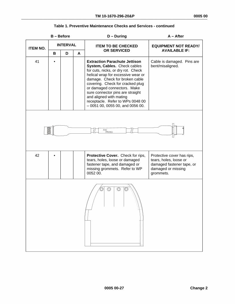
TM 10-1670-296-20&P 0005 00 ________________________________________________________________________________________________
0005 00-27 Change 2
Table 1. Preventive Maintenance Checks and Services - continued
B – Before D – During A – After
INTERVAL ITEM NO.
B D A ITEM TO BE CHECKED
OR SERVICED EQUIPMENT NOT READY/
AVAILABLE IF:
41 • Extraction Parachute Jettison System, Cables. Check cables for cuts, nicks, or dry rot. Check helical wrap for excessive wear or damage. Check for broken cable covering. Check for cracked plug or damaged connectors. Make sure connector pins are straight and aligned with mating receptacle. Refer to WPs 0048 00 – 0051 00, 0055 00, and 0056 00.
Cable is damaged. Pins are bent/misaligned.
FXC P/N 811-
42 • Protective Cover. Check for rips, tears, holes, loose or damaged fastener tape, and damaged or missing grommets. Refer to WP 0052 00.
Protective cover has rips, tears, holes, loose or damaged fastener tape, or damaged or missing grommets.

TM 10-1670-296-20&P 0005 00 ________________________________________________________________________________________________
Change 2 0005 00-28
Table 1. Preventive Maintenance Checks and Services - continued
B – Before D – During A – After
INTERVAL ITEM NO.
B D A ITEM TO BE CHECKED
OR SERVICED EQUIPMENT NOT READY/
AVAILABLE IF:
43 • Y-Connector Mounting Box Tie-down Bracket (C-5). Check tie-down bracket for missing components, ability to mount Y-connector mounting box, and damage. Refer to WP 0054 00.
Tie-down bracket cannot secure Y-connector mounting box.
44 • Safety Cap. Check that safety cap is installed on squib cable and for damage. Refer to WP 0057 00.
Safety cap is missing or damaged.

TM 10-1670-296-20&P 0005 00 ________________________________________________________________________________________________
0005 00-29 Change 2
Table 1. Preventive Maintenance Checks and Services - continued
B – Before D – During A – After
INTERVAL ITEM NO.
B D A ITEM TO BE CHECKED
OR SERVICED EQUIPMENT NOT READY/
AVAILABLE IF:
45 • Initiator Simulator. Check for missing components and damage affecting functionality. Functional check before every use. Refer to WP 0058 00.
Calibration is 180 days.
Initiator simulator is not complete or obvious damage is found affecting functionality. Fails test procedure in WP 0058 00.
Calibration date is missing.
46 • Squib Tester. Check for missing components and damage affecting functionality. Batteries are serviceable and LEDs illuminate. Refer to WP 0059 00.
Squib tester is not complete or obvious damage is found affecting functionality. Batteries are dead or LEDs do not illuminate.

TM 10-1670-296-20&P 0005 00 ________________________________________________________________________________________________
Change 2 0005 00-30
Table 1. Preventive Maintenance Checks and Services - continued B – Before D – During A – After
INTERVAL ITEM NO.
B D A ITEM TO BE CHECKED
OR SERVICED EQUIPMENT NOT READY/
AVAILABLE IF:
47 • 28 VDC Power Supply. Check for missing components and damage affecting functionality. Refer to WP 0060 00.
28 VDC power supply is not complete or obvious damage is found affecting functionality.
48 • Link, Parachute Connector. Inspect link for rough areas, bends or cracks.
Link, Parachute Connector has rough areas, bends, or cracks. Detent spring does not operate freely.
49 • Safety Pin. Check safety pin for proper detent function and that warning tag is present. Refer to WP 0044 00 and 0044 01.
Safety pin detent not functioning properly or warning tag is missing.
AND STORE INTO HOLE ON TOP OF LINKAND STORE INTO HOLE ON TOP OF LINKPRIOR TO AIRDROP REMOVE PIN FROM KNIFEPRIOR TO AIRDROP REMOVE PIN FROM KNIFE
WARNINGWARNING
END OF TABLE
END OF WORK PACKAGE

TM 10-1670-296-20&P 0006 00 ________________________________________________________________________________________________
0006 00-1 Change 2
ANCILLARY EQUIPMENT FOR LOW VELOCITY AIR DROP SYSTEMS (LVADS) PREVENTIVE MAINTENANCE CHECKS AND SERVICES (PMCS) AFTER PROCEDURES
NOTE
All PMCS inspections will be a Technical/Rigger Inspection.
Table 2. Preventive Maintenance Checks and Services
B – Before D – During A – After
INTERVAL ITEM NO.
B D A ITEM TO BE CHECKED
OR SERVICED EQUIPMENT NOT READY/
AVAILABLE IF:
1 • Multi-Loop Line. Inspect multi-loop link for loose or broken stitching, cuts, worn or frayed webbing and presence of foreign matter. Refer to WP 0012 00.
Multi-loop line has loose or broken stitching, cuts, worn or frayed webbing, or foreign matter present.

TM 10-1670-296-20&P 0006 00 ________________________________________________________________________________________________
Change 2 0006 00-2
Table 2. Preventive Maintenance Checks and Services - continued
B – Before D – During A – After
INTERVAL ITEM NO.
B D A ITEM TO BE CHECKED
OR SERVICED EQUIPMENT NOT READY/
AVAILABLE IF:
2 • Extraction Force Transfer Coupling. Inspect extraction force transfer coupling for presence of foreign matter. Ensure that all parts are present and securely fastened together. Refer to WP 0013 00.
Extraction force transfer coupling is not complete or has foreign matter present.

TM 10-1670-296-20&P 0006 00 ________________________________________________________________________________________________
0006 00-3 Change 2
Table 2. Preventive Maintenance Checks and Services - continued
B – Before D – During A – After
INTERVAL ITEM NO.
B D A ITEM TO BE CHECKED
OR SERVICED EQUIPMENT NOT READY/
AVAILABLE IF:
3 • EFTC Link Adapter Assembly. Inspect link assembly adapter for rough areas, bends, or cracks. Ensure that threads are not stripped or damaged. Refer to WP 0014 00.
Link assembly adapter has rough areas, bends, or cracks. Threads are stripped.
4 • EFTC 3-Point Link Adapter Assembly. Inspect link assembly, coupling for rough areas, bends, or cracks. Ensure that threads are not stripped or damaged. Refer to WP 0015 00.
Link assembly, coupling has rough areas, bends, or cracks. Threads are stripped.

TM 10-1670-296-20&P 0006 00 ________________________________________________________________________________________________
Change 2 0006 00-4
Table 2. Preventive Maintenance Checks and Services - continued
B – Before D – During A – After
INTERVAL ITEM NO.
B D A ITEM TO BE CHECKED
OR SERVICED EQUIPMENT NOT READY/
AVAILABLE IF:
5 • EFTC Latch Assembly. Inspect latch assembly coupling for rough areas, bends, cracks, or foreign material. Check that the retainer hook releases when the latch assembly adapter is activated. Refer to WP 0017 00.
Latch assembly coupling has rough areas, bends, or cracks, or foreign material is present. Retainer hook does not release when the latch assembly adapter is activated.
6 • Latch Connector Assembly. Inspect for rough areas, bends or cracks. Ensure the threads are not stripped or damaged. Refer to WP 0016 00.
Assembly has rough areas, bends or cracks. Threads are stripped.

TM 10-1670-296-20&P 0006 00 ________________________________________________________________________________________________
0006 00-5 Change 2
Table 2. Preventive Maintenance Checks and Services - continued
B – Before D – During A – After
INTERVAL ITEM NO.
B D A ITEM TO BE CHECKED
OR SERVICED EQUIPMENT NOT READY/
AVAILABLE IF:
7 • EFTC Cable Assembly. Inspect cable for bends or kinks. Check that cable moves freely within its cover. Ensure that cable’s cover is not broken, that the terminals operate properly, and that the threads are not stripped or damaged. Ensure the adjusting collar set screws are tight. Inspect yokes for rough areas, bends, or cracks. Ensure that shank pins and cotter pins are present. Refer to WP 0018 00.
Cable has bends or kinks. Cable does not move freely within its cover. Cable’s cover is broken or damaged. Terminals do not operate properly or threads are stripped or damaged. Adjusting collar set screws are loose. Yokes have rough areas, bends, or cracks. Shank pins or cotter pins are missing.
8 • EFTC Actuator Assembly. Check assembly operation. Inspect for excessive wear, bends, breaks, or weld separation. Ensure that threads are not stripped or damaged. Check that safety pin and cam arm spring are present. Ensure that actuator arm is not bent, the axle nut is not loose, and there is not excessive play between arm and axle. Refer to WP 0019 00.
Assembly is inoperable or has excessive wear, bends, breaks, or weld separation. Threads are stripped or damaged. Safety pin or cam arm spring is missing. Actuator arm is bent, the axle nut is loose, or there is excessive play between arm and axle.

TM 10-1670-296-20&P 0006 00 ________________________________________________________________________________________________
Change 2 0006 00-6
Table 2. Preventive Maintenance Checks and Services - continued
B – Before D – During A – After
INTERVAL ITEM NO.
B D A ITEM TO BE CHECKED
OR SERVICED EQUIPMENT NOT READY/
AVAILABLE IF:
9 • M-1 Cargo Parachute Release. Check release operation. Ensure that, when using a 15-second timer, it activates within 12 and 16-seconds. Check for excessive wear or foreign material. Refer to WP 0020 00.
Release does not operate properly. Timer is not accurate. Release is worn or has foreign material present.
NOTE The original Face Plate Bolts, NSN 5306-00-207-8362/Part Number AN6-25A has been temporarily replaced by NSN 5306-00-638-5821/Part Number AN6H-25A (H denotes a hole drilled in the bolt head). Either bolt is acceptable until the original bolt is brought back into the inventory.

TM 10-1670-296-20&P 0006 00 ________________________________________________________________________________________________
0006 00-7 Change 2
Table 2. Preventive Maintenance Checks and Services - continued
B – Before D – During A – After
INTERVAL ITEM NO.
B D A ITEM TO BE CHECKED
OR SERVICED EQUIPMENT NOT READY/
AVAILABLE IF:
10 • Lanyard Arming Wire. Inspect lanyard for loose or broken stitching, cuts, worn, or frayed webbing, and presence of foreign matter. Refer to WP 0020 00.
Lanyard has loose or broken stitching, cuts, or worn or frayed webbing, or foreign material is present.
11 • Parachute Connector. Inspect connector for bends, cracks, burrs, and rough areas. Check if threads are stripped or cracked. Check if arms engage into the retainer clamp. Refer to WP 0022 00.
Connector has bends, burrs, or rough areas. Threads are stripped or cracked. Arms do not engage into the retaining clamp.

TM 10-1670-296-20&P 0006 00 ________________________________________________________________________________________________
Change 2 0006 00-8
Table 2. Preventive Maintenance Checks and Services - continued
B – Before D – During A – After
INTERVAL ITEM NO.
B D A ITEM TO BE CHECKED
OR SERVICED EQUIPMENT NOT READY/
AVAILABLE IF:
12 • Timer Delay Assembly. Inspect timer assembly for bends, cracks, burrs, rough areas, and foreign material. Check if timer activates at the appropriate time and if stem rotates freely in mounting block. Ensure that keys retract at the end of timing sequence. Refer to WP 0023 00.
Timer assembly has bends, cracks, burrs, or rough areas or foreign material is present. Timer does not activate at the appropriate time or stem does not rotate freely in mounting block. Keys do not retract at the end of time sequence.
13 • Lower Link Suspension. Inspect link for bends, breaks, cracks, burrs, and rough areas. Check for stripped or damaged threads. Refer to WP 0020 00.
Link has bends, breaks, cracks. Surfaces have burrs or rough areas. Threads are stripped or damaged.

TM 10-1670-296-20&P 0006 00 ________________________________________________________________________________________________
0006 00-9 Change 2
Table 2. Preventive Maintenance Checks and Services - continued
B – Before D – During A – After
INTERVAL ITEM NO.
B D A ITEM TO BE CHECKED
OR SERVICED EQUIPMENT NOT READY/
AVAILABLE IF:
14 • M-2 Cargo Parachute Release (42,000-lbs). Check release operation. Ensure that, when using a 15-second timer, it activates within 12 and 16-seconds. Check for excessive wear or foreign material. Check lanyard for frayed material, cuts, and loose or broken stitching. Refer to WP 0021 00.
Release does not operate properly. Timer is not accurate. Release is worn or has foreign material present.
15 • Type IV Single Suspension Link Assembly. Inspect link for bends, breaks, cracks, burrs, or rough areas. Ensure proper operation of button and lock. Refer to WP 0024 00.
Link has bends, breaks, cracks. Surfaces have burrs or rough areas. Button or lock does not function properly.
NOTE No longer authorized for LVAD after 31 December 2003.

TM 10-1670-296-20&P 0006 00 ________________________________________________________________________________________________
Change 2 0006 00-10
Table 2. Preventive Maintenance Checks and Services - continued
B – Before D – During A – After
INTERVAL ITEM NO.
B D A ITEM TO BE CHECKED
OR SERVICED EQUIPMENT NOT READY/
AVAILABLE IF:
16 • Heavy-Duty Link Assembly. Inspect plates and spacers for rough areas, bends, breaks, or cracks. Ensure that threads are not stripped or damaged. Refer to WP 0025 00.
Plate or spacer has rough areas, bends, breaks, or cracks. Threads are damaged or stripped.
17 • 4-Point Link. Inspect four-point link for rough areas, bends, breaks, and cracks. Ensure fastener threads are not stripped or damaged. Refer to WP 0026 00.
Link has rough areas, bends, breaks, and cracks. Fasteners have stripped or damaged threads.

TM 10-1670-296-20&P 0006 00 ________________________________________________________________________________________________
0006 00-11 Change 2
Table 2. Preventive Maintenance Checks and Services - continued
B – Before D – During A – After
INTERVAL ITEM NO.
B D A ITEM TO BE CHECKED
OR SERVICED EQUIPMENT NOT READY/
AVAILABLE IF:
18 • Type IV Cover Link. Inspect cover for loose or broken stitches, tears, damaged cord, or foreign material. Refer to WP 0027 00.
Cover has loose or broken stitches, tears, damaged cord, or foreign matter present.
NOTE
No longer authorized for LVAD after 31 December 2003.
19 • Aerial Delivery Clevis. Inspect clevis for rough areas, bends, breaks, and cracks. Ensure fastener threads are not stripped or damaged. Refer to WP 0028 00.
Clevis has rough areas, bends, breaks, and cracks. Fasteners have stripped or damaged threads.

TM 10-1670-296-20&P 0006 00 ________________________________________________________________________________________________
Change 2 0006 00-12
Table 2. Preventive Maintenance Checks and Services - continued
B – Before D – During A – After
INTERVAL ITEM NO.
B D A ITEM TO BE CHECKED
OR SERVICED EQUIPMENT NOT READY/
AVAILABLE IF:
20 • Clevis Cover. Inspect cover for loose or broken stitches, tears, broken grommets, or foreign material. Refer to WP 0029 00.
Cover has loose or broken stitches, tears, grommets are broken, or foreign material is present.
21 • Single Knife Parachute Release Strap. Inspect strap for loose or broken stitching, cuts, worn and frayed webbing, or presence of foreign material. Check knife and fastener for rough areas, bends, breaks, and cracks. Check knife-edge for sharpness. Ensure that ferrule operates properly. Refer to WP 0030 00.
Strap has loose or broken stitching, cuts, worn or frayed webbing, or foreign material is present. Knife or fastener has rough areas, bends, breaks, or cracks. Knife-edge is dull. Ferrule does not cover the safety aperture when unscrewed to the full open position.

TM 10-1670-296-20&P 0006 00 ________________________________________________________________________________________________
0006 00-13 Change 2
Table 2. Preventive Maintenance Checks and Services - continued
B – Before D – During A – After
INTERVAL ITEM NO.
B D A ITEM TO BE CHECKED
OR SERVICED EQUIPMENT NOT READY/
AVAILABLE IF:
22 • Multi-Knife Parachute Release Strap. Inspect strap for loose or broken stitching, cuts, worn and frayed webbing, or presence of foreign material. Check knives for rough areas, bends, breaks, and cracks and knife-edges for sharpness. Ensure that ferrules operate properly. Refer to WP 0031 00.
Strap has loose or broken stitching, cuts, worn or frayed webbing, or foreign material is present. A knife has rough areas, bends, breaks, or cracks or its edge is dull. A ferrule does not cover the safety aperture when unscrewed to the full open position.
23 • 3-Point Coupling Link Assembly. Inspect three-point link for rough areas, bends, breaks, and cracks. Ensure fastener threads are not stripped or damaged. Refer to WP 0032 00.
Link has rough areas, bends, breaks, and cracks. Fasteners have stripped or damaged threads.

TM 10-1670-296-20&P 0006 00 ________________________________________________________________________________________________
Change 2 0006 00-14
Table 2. Preventive Maintenance Checks and Services - continued
B – Before D – During A – After
INTERVAL ITEM NO.
B D A ITEM TO BE CHECKED
OR SERVICED EQUIPMENT NOT READY/
AVAILABLE IF:
24 • M-35 Suspension Bracket. Inspect bracket for rough areas, bends, breaks, and cracks. Ensure fastener threads are not stripped or damaged. Refer to WP 0033 00.
Bracket as rough areas, bends, breaks, and cracks. Fasteners have stripped or damaged threads.
25 • M-59 Suspension Bracket. Inspect bracket for rough areas, bends, breaks, and cracks. Ensure fastener threads are not stripped or damaged. Refer to WP 0034 00.
Bracket has rough areas, bends, breaks, and cracks. Fasteners have stripped or damaged threads.

TM 10-1670-296-20&P 0006 00 ________________________________________________________________________________________________
0006 00-15 Change 2
Table 2. Preventive Maintenance Checks and Services - continued
B – Before D – During A – After
INTERVAL ITEM NO.
B D A ITEM TO BE CHECKED
OR SERVICED EQUIPMENT NOT READY/
AVAILABLE IF:
26 • Suspension Plate. Inspect plate for rough areas, bends, breaks, and cracks. Refer to WP 0035 00.
Plate has rough areas, bends, breaks, and cracks.
27 • 10K Cargo Tie-down. Inspect tie-down for loose or broken stitching, frayed webbing, foreign material, or a defective binder. Refer to WP 0036 00.
Tie-down has loose or broken stitching or frayed webbing, foreign material is present, or the binder is defective.

TM 10-1670-296-20&P 0006 00 ________________________________________________________________________________________________
Change 2 0006 00-16
Table 2. Preventive Maintenance Checks and Services - continued
B – Before D – During A – After
INTERVAL ITEM NO.
B D A ITEM TO BE CHECKED
OR SERVICED EQUIPMENT NOT READY/
AVAILABLE IF:
28 • Quick Release Cargo Tie-down. Inspect tie-down for loose or broken stitching, frayed webbing, foreign material, or a defective quick-release lever. Refer to WP 0037 00.
Tie-down has loose or broken stitching or frayed webbing, foreign material is present, or the quick-release lever is defective.
29 • Type IV Drive-Off Aid. Inspect drive-off aid for loose or broken stitching, frayed webbing, or foreign material. Refer to WP 0038 00.
Drive-off aid has loose or broken stitching or frayed webbing. Foreign material is present.

TM 10-1670-296-20&P 0006 00 ________________________________________________________________________________________________
0006 00-17 Change 2
Table 2. Preventive Maintenance Checks and Services - continued
B – Before D – During A – After
INTERVAL ITEM NO.
B D A ITEM TO BE CHECKED
OR SERVICED EQUIPMENT NOT READY/
AVAILABLE IF:
30 • Aircraft Cargo Tie-down. Inspect tie-down chain for rough areas, bends, breaks, cracks, rust, or foreign material. Ensure turnbuckle threads are not stripped or damaged. Refer to WP 0039 00.
Tie-down chain has rough areas, bends, breaks, or cracks. Rust, or foreign material is present. Turnbuckle threads are stripped or damaged.
31 • 3 ¾-Inch, 2-Point Link. Inspect two-point link for rough areas, bends, breaks, and cracks. Ensure fastener threads are not stripped or damaged. Refer to WP 0040 00.
Link has rough areas, bends, breaks, and cracks. Fasteners have stripped or damaged threads.

TM 10-1670-296-20&P 0006 00 ________________________________________________________________________________________________
Change 2 0006 00-18
Table 2. Preventive Maintenance Checks and Services - continued
B – Before D – During A – After
INTERVAL ITEM NO.
B D A ITEM TO BE CHECKED
OR SERVICED EQUIPMENT NOT READY/
AVAILABLE IF:
32 • 5 ½-Inch, 2-Point Link. Inspect two-point link for rough areas, bends, breaks, and cracks. Ensure fastener threads are not stripped or damaged. Refer to WP 0041 00.
Link has rough areas, bends, breaks, and cracks. Fasteners have stripped or damaged threads.
33 • Release Away Static Line Assembly. Check for loose or broken stitches. Inspect for frays, burns cuts or tears in webbing and sleeve. Check for loose or broken stitches, as well as missing or damaged hardware (grommets, 1-inch connector link). Ensure release line can move freely and there are no visible twists. Refer to WP 0042 00.
Static line has loose or broken stitching or frayed or cut webbing, damaged or missing hardware. Release does not move freely or is twisted.

TM 10-1670-296-20&P 0006 00 ________________________________________________________________________________________________
0006 00-19 Change 2
Table 2. Preventive Maintenance Checks and Services - continued
B – Before D – During A – After
INTERVAL ITEM NO.
B D A ITEM TO BE CHECKED
OR SERVICED EQUIPMENT NOT READY/
AVAILABLE IF:
34 • Extraction Parachute Jettison System. Check all cables for damage.
Check EPJD for squib-fired condition. Refer to WP 0043 00.
Cable is damaged.
Squib is fired.
CONTROLBOX
Y CONNECTOR Y CONNECTOR Y CONNECTOR Y CONNECTOR
28 VDCPOWERSUPPLY
115 VACPOWERCABLE
POWERCABLE
MAIN CABLE INTERCONNECTCABLE
PLATFORMCABLE
INITIATORSIMULATOR
INTERCONNECTCABLE
INTERCONNECTCABLE
PLATFORMCABLE
INITIATORSIMULATOR
35 • Extraction Parachute Jettison Device. Check device for presence of foreign matter. Ensure that all parts are present and securely fastened together. Ensure safety pin is installed in cutter block on EPJD-H. Ensure squib installation date is notated. Refer to WP 0044 00 and WP 0044 01. On EPJD-H observe that ball detents retract when center button is depressed to unlock the pins.
Device is not complete or has foreign matter present. Squib installation date is not notated or exceeds specified limit. On EPJD-H ball detents fail to retract.
WARNINGPRIOR TO AIRDROP REMOVE PIN FROM KNIFE
AND STORE INTO HOLE ON TOP OF LINK
EPJD EPJD-H

TM 10-1670-296-20&P 0006 00 ________________________________________________________________________________________________
Change 2 0006 00-20
Table 2. Preventive Maintenance Checks and Services - continued
B – Before D – During A – After
INTERVAL ITEM NO.
B D A ITEM TO BE CHECKED
OR SERVICED EQUIPMENT NOT READY/
AVAILABLE IF:
36 • Y-Connector. Check Y-connector for secure attachment. Ensure LED illuminates when lamp test is depressed. Refer to WP 0045 00.
Y-connector has been forced off mounting area. LED does not illuminate when lamp test is depressed.
37 • Y-Connector Mounting Box (C-130, C-141, C-17). Check Y-connector mounting box for missing components, proper operation of extendable arms, ability to mount Y-connector to both positions, and damage. Refer to WP 0046 00.
Mounting box cannot secure Y-connector.

TM 10-1670-296-20&P 0006 00 ________________________________________________________________________________________________
0006 00-21 Change 2
Table 2. Preventive Maintenance Checks and Services - continued
B – Before D – During A – After
INTERVAL ITEM NO.
B D A ITEM TO BE CHECKED
OR SERVICED EQUIPMENT NOT READY/
AVAILABLE IF:
38 • Y-Connector Mounting Box (C-5). Check Y-connector mounting box for missing components, ability to mount Y-connector, and damage. Refer to WP 0046 00.
Mounting box cannot secure Y-connector or tie-down bracket.
39 • Control Box. Check for missing components and damage affecting serviceability. Refer to WP 0047 00.
Box is not complete or obvious damage is found affecting functionality.

TM 10-1670-296-20&P 0006 00 ________________________________________________________________________________________________
Change 2 0006 00-22
Table 2. Preventive Maintenance Checks and Services - continued
B – Before D – During A – After
INTERVAL ITEM NO.
B D A ITEM TO BE CHECKED
OR SERVICED EQUIPMENT NOT READY/
AVAILABLE IF:
40 • Squib Cable. Check flexible cable wrap for excessive abrasions, cuts, wear, and deformation. Check connector pins using pin gauge. Refer to WP 0044 00 or WP 0044 01.
Cable wrap is damaged to the point of losing protective function. Connector pins are damaged, missing or recessed.
41 • Extraction Parachute Jettison System Cables. Check all cables for cuts, nicks, and dry rot. Check for broken cable covering. Check for cracked plug or connectors. Make sure connector pins are straight and aligned with mating receptacle. Refer to WPs 0048 00 – 0051 00, 0055 00, and 0056 00.
Cable is damaged.
42 • Protective Cover. Check cover for rips, tears, holes, loose or damaged fastener tape, and damaged or missing grommets. Refer to WP 0052 00.
Protective cover has rips, tears, holes, loose or damaged fastener tape, and damaged or missing grommets.

TM 10-1670-296-20&P 0006 00 ________________________________________________________________________________________________
0006 00-23 Change 2
Table 2. Preventive Maintenance Checks and Services - continued
B – Before D – During A – After
INTERVAL ITEM NO.
B D A ITEM TO BE CHECKED
OR SERVICED EQUIPMENT NOT READY/
AVAILABLE IF:
43 • Y-Connector Mounting Box Tie-down Bracket (C-5). Check tie-down bracket for missing components, ability to mount Y-connector mounting box, and damage. Refer to WP 0054 00.
Tie-down bracket cannot secure Y-connector mounting box.
44 • Safety Cap. Check that safety cap is installed on squib cable, and for damage. Refer to WP 0057 00.
Safety cap is missing or damaged.

TM 10-1670-296-20&P 0006 00 ________________________________________________________________________________________________
Change 2 0006 00-24
Table 2. Preventive Maintenance Checks and Services - continued
B – Before D – During A – After
INTERVAL ITEM NO.
B D A ITEM TO BE CHECKED
OR SERVICED EQUIPMENT NOT READY/
AVAILABLE IF:
45 • Initiator Simulator. Check for missing components and damage affecting functionality. Functional check before every use. Refer to WP 0058 00.
Initiator simulator is not complete or obvious damage is found affecting functionality. Fails test procedure in WP 0058 00.
46 • Squib Tester. Check for missing components and damage affecting functionality. Batteries are serviceable and LEDs illuminate. Refer to WP 0059 00.
Squib tester is not complete or obvious damage is found affecting functionality. Batteries are dead, or LEDs do no illuminate.

TM 10-1670-296-20&P 0006 00 ________________________________________________________________________________________________
0006 00-25 Change 2
Table 2. Preventive Maintenance Checks and Services - continued
B – Before D – During A – After
INTERVAL ITEM NO.
B D A ITEM TO BE CHECKED
OR SERVICED EQUIPMENT NOT READY/
AVAILABLE IF:
47 • 28 VDC Power Supply. Check for missing components and damage affecting functionality. Refer to WP 0060 00.
28 VDC power supply is not complete or obvious damage is found affecting functionality.
OFFPOWER
ON
CORPORATION
28 VDC
A B
OFFPOWER
ON
CORPORATION
28 VDC
A B
48 • Link, Parachute Connector. Inspect link for rough areas, bends or cracks.
Link, Parachute Connector has rough areas, bends, or cracks. Detent spring does not operate freely.
49 • Safety Pin. Check safety pin for proper detent function and that warning tag is present. Refer to WP 0044 00 and 0044 01.
Safety pin detent not functioning properly or warning tag is missing.
AND STORE INTO HOLE ON TOP OF LINKAND STORE INTO HOLE ON TOP OF LINKPRIOR TO AIRDROP REMOVE PIN FROM KNIFEPRIOR TO AIRDROP REMOVE PIN FROM KNIFE
WARNINGWARNING
END OF TABLE

TM 10-1670-296-20&P 0006 00 ________________________________________________________________________________________________
Change 2 0006 00-26
AFTER USE RECEIPT Used equipment will be processed as prescribed in this WP. LUBRICATION SERVICE INTERVALS The ancillary airdrop equipment does not require lubrication services.
END OF WORK PACKAGE

TM 10-1670-296-20&P
CHAPTER 3
UNIT MAINTENANCE INSTRUCTIONS
FOR
ANCILLARY EQUIPMENT FOR
LOW VELOCITY AIR DROP SYSTEMS (LVADS)


TM 10-1670-296-20&P 0007 00
UNIT MAINTENANCE ANCILLARY EQUIPMENT FOR LOW VELOCITY AIR DROP SYSTEMS (LVADS) INSPECTION
0007 00-1
THIS TASK COVERS:
Technical/Rigger-Type
Routine Inspection
In-Storage
Equipment Disposition
INITIAL SETUP:
Equipment Condition Laid out on packing table or other suitable surface.
Personnel Required Two, 92R (10) Parachute Rigger
References DA PAM 738-751; TB 43-002-43; DA PAM 738-750; AR 750-1; WP 008 00; WP 0064 00
TECHNICAL/RIGGER INSPECTION Technical/rigger-type inspection is a complete and thorough inspection of an individual airdrop item, including associated parts and components. The following paragraphs outline criteria applicable to accomplishing a technical/rigger-type inspection. The inspection will be performed by a qualified parachute rigger in accordance with AR 750-32 (AF AFSCs 2T251/2A754/1A251 trained and certified by USAQMC&S Fabrication of Aerial Delivery Loads Course).
Inspection Intervals
1. Upon initial receipt of procured equipment to a using unit by a supply source.
2. Immediately before equipment is packed or rigged for use in airdrop operations.
3. Before and after repairs or modifications are made.
4. At any other time as deemed necessary by the airdrop equipment maintenance officer.
Inspection Function Requirement. Normally, a technical/rigger-type inspection will be performed at a packing, rigging, or repair activity. The inspection of initial receipt items will be performed as a separate function from packing or rigging operations.
When the inspection is conducted at a rigging activity, the item to be inspected will be placed in proper layout on a packing table or a suitable sized floor area. Should a defect or damage be discovered at any point during the inspection, the inspection will be terminated and the defective item will be processed and forwarded to a repair activity. The repair activity, in turn, will conduct a technical/rigger-type inspection that will be performed by only those parachute rigger personnel cited in AR 750-32.
Any defect discovered during a unit level repair activity that exceeds the capability of that activity will require the affected item to be evacuated to a direct support maintenance facility determination of economic repair and its application, if applicable.

TM 10-1670-296-20&P 0007 00
0007 00-2
Technical/Rigger-Type Inspection Procedures
1. Overall Inspection. An overall inspection will be made of airdrop equipment to check to following:
a. Log Record/Parachute Inspection Data Pocket and Form. As applicable, inspect the assembly log record/parachute inspection data pocket to ensure the Army Parachute Log Record (DA Form 3912) is enclosed and properly attached. Further, remove the log record from the item and evaluate the recorded items.
b. Assembly Completeness. Ensure that the applicable assembly is complete and no components or parts are missing.
c. Operational Adequacy. Check the item components and parts to ensure proper assembly that includes attachment and alignment, and that the assembled product functions in the prescribed manner. Further, ensure that no stitch formation or sewn seam has been omitted.
d. Markings and Paint. Inspect each assembly and related components for faded, illegible, obliterated, or missing informational data, identification numbers, and warning marks. Check for chipped, worn or peeled paint, if applicable.
e. Foreign Material and Stains. Inspect each assembly and related components for dirt or other foreign material. Also check for evidence of mildew, moisture, oil, grease, resin, or peeled paint, as applicable.
2. Detailed Inspection. In addition to the overall inspection performed in the OVERALL INSPECTION paragraph, above, a detailed inspection will be performed in the materials that constitute the assembly or component construction using the following criteria, as applicable:
a. Metal. Inspect for rust, corrosion, dents, breaks, burrs, rough spots, sharp edges, wear, or deterioration, damaged, loose, or missing nuts, bolts, screws, safety pins, or rivets, improper welding, or loss of spring tension.
b. Plastic and Wood. Inspect for bends, breaks, dents, holes, rough spots, sharp edges, and wear.
c. Cloth. Inspect for breaks, burns, cuts, frays, holes, rips, snags, or tears, loose, missing, or broken stitching or tacking, weak spots, wear, or deterioration.
d. Fabric Type, Webbing, and Cordage. Inspect for breaks, burns, cuts, frays, holes, snags, incorrect weaving, and sharp edges formed from searing, loose, missing, or broken stitching, tacking, shipping, and sealing, weak spots, wear, and deterioration.
e. Pressure Sensitive (Adhesive) Tape. Inspect for burns, cuts, holes, tears, and weak spots, looseness, and deterioration.
f. Rubber and Elastic. Inspect for burns, cuts, holes, tears, and weak spots, loss of elasticity, and deterioration.
g. Leather. Inspect for burns, cuts, holes, tears, loose, missing, or broken stitching, thin spots, and deterioration.
ROUTINE INSPECTIONA routine inspection is a visual check of the serviceability of all visible components of an airdrop item that is packed or rigged for use. The inspection will be made on all components that can be inspected without de-rigging the load. All LVADS Ancillary Equipment will be administered a routine inspection by a parachute rigger prior to issue.

TM 10-1670-296-20&P 0007 00
0007 00-3
IN-STORAGE INSPECTION An in-storage inspection is a physical check conducted on a random sample of airdrop equipment that is located in storage. The purpose of the inspection is to ensure that the equipment is ready for issue, that the item is properly identified and segregated from other types of equipment, that no damage or deterioration of equipment has been incurred, and that all modifications or similar action requirements have been completed. The inspection shall also concern the methods and procedures applied to the storage of airdrop items, the adequacy of storage facilities, efforts of pest and rodent control, and protection against unfavorable climatic conditions. Airdrop equipment that is in storage will be inspected at least semiannually and at more frequent intervals if prescribed by the local parachute maintenance officer. The frequency of inspection may vary according to the type of storage facilities and local climatic conditions. Only parachute rigger personnel designated by the local parachute maintenance officer will conduct in-storage inspections.
Malfunctioning Equipment. Dispose of any airdrop equipment that shows any evidence of malfunction or defect during or after a drop-test. If it has been used, is unserviceable, but has not exceeded normal fair wear or aging criteria, tag the equipment as prescribed in DA PAM 738-751. Report the equipment on an Equipment Improvement Report (EIR) in accordance with DA PAM 738-751 and AR 750-1. Hold the equipment as an EIR exhibit as outlined in DA PAM 738-750, pending receipt of disposition instructions from the National Maintenance Point (NMP). Do not tamper with the applicable item or make any attempt to discover the cause of the malfunction. Unnecessary handling of EIR equipment may hamper the judgment of the engineering personnel responsible for the final evaluation of EIR actions.
Non-Malfunctioning Equipment. Administer a technical/rigger-type inspection to equipment that does not show evidence of malfunction or defect, as outlined in this WP. If serviceable, the item (s) may then remain in use.
EQUIPMENT DISPOSITION Airdrop equipment may be rendered unserviceable by either normal fair wear or by aging and will subsequently be repaired, modified, or condemned, as appropriate. Equipment that is uneconomically reparable (outdated) will be condemned. Disposition of airdrop equipment that is condemned, unserviceable, or for which the serviceability is questionable, will be accomplished using the following procedures, as applicable.
1. Item requiring repair or modification. An airdrop item that requires repair or modification will be tagged in accordance with DA PAM 738-751. Subsequent work on the item will be performed at the maintenance level specified in the MAC, WP 0064 00.
2. Disposition of condemned air delivery equipment. Condemned equipment, other than fatality parachutes, will be removed from service and disposed of in accordance with current directives listed in this WP.
3. Rejected equipment. Equipment which, prior to use, is deemed unserviceable for use will be reported in an Equipment Improvement Recommendation (EIR) in accordance with DA PAM 738-751, as authorized by AR 750-1. Each applicable item that is defective will be held and safeguarded pending receipt of disposition instructions from the National Maintenance Point (NMP). In all instances, EIR exhibit material will be handled as prescribed in DA PAM 738-750. If the quality or the serviceability of an item is questionable, clarification and assistance may be obtained by contacting Commander, US Army Soldier and Biological Chemical Command, ATTN: AMSSB-RIM-E (N), Kansas Street, Natick, MA 01760-5052.

TM 10-1670-296-20&P 0007 00
0007 00-4
4. Equipment of doubtful serviceability. Equipment which has had previous use and has not exceeded normal fair wear or aging criteria, but of which further serviceability is doubtful, will be tagged as prescribed in DA PAM 738-751. In addition, the equipment will be reported in an EIR in accordance with DA Pam 738-750 and AR 750-1. The item (s) in question will be held as EIR exhibit material as outlined in DA PAM 738-750 pending receipt of disposition instructions from the NMP. A maintenance activity holding EIR exhibit material will not tamper with the applicable item(s) or make any attempt to ascertain cause factors. Unnecessary handling or EIR exhibit material may disturb or alter peculiar aspects of the affected item(s) which might affect the judgment of engineering personnel who have the responsibility for final evaluation of EIR actions.
5. Equipment immersed in salt-water. Any airdrop item constructed from cotton material that has been immersed in salt water will be condemned. Cotton thread used for tacking and sewing on nylon parachute packs that have been immersed in salt water will only be replaced when there is visible evidence of deterioration such as extreme discoloration or indications of broken thread. Any airdrop equipment constructed of nylon or rayon material that has been immersed in salt water in excess of 24- hours will be condemned. Additionally, any nylon or rayon airdrop item that has been immersed in salt water for a period less than 24-hours, but which cannot be rinsed within 48-hours after recovery will also be condemned. However, if the cited time limitations can be met, then immediately upon recovery, suspend or elevate the recovered equipment in a shaded area and allow the item(s) to drain for at least 5-minutes. Do not attempt to wring the equipment fabric or the suspension lines. Within 48-hours after recovery, under the supervision of a qualified parachute rigger (92R), rinse the recovered equipment as indicated in WP 0008 00, CLEANING AND DRYING.
END OF WORK PACKAGE

TM 10-1670-296-20&P 0008 00
UNIT MAINTENANCE ANCILLARY EQUIPMENT FOR LOW VELOCITY AIR DROP SYSTEMS (LVADS) CLEANING AND DRYING
0008 00-1
THIS TASK COVERS:
Cleaning Fabric Items With Dishwashing Compound
Drying Fabric Items
Cleaning Metal Items
Rinsing Equipment Immersed in Salt-water
Rinsing Equipment Immersed in Fresh-water
INITIAL SETUP:
Materials/Parts Cloth, Abrasive (Item 6, WP 0125 00) Dishwashing Compound (Item 10, WP 0125 00) Lubricant, Solid Film (Item 20, WP 0125 00) Rag, Wiping (Item 25, WP 0125 00)
ToolsBrush, Scrub, Household (Item 2, WP 0064 00) File, Flat (Item 10, WP 0064 00)
Equipment Condition Laid out on packing table or other suitable surface.
Personnel Required Two, 92R (10) Parachute Rigger
References WP 0003 00, WP 0007 00, WP 006400
CAUTION
If, during the cleaning, there exists a possibility that the substance to be removed contains acid or some other equally destructive ingredient, the item will be evacuated to intermediate maintenance activity for determination as to the nature of the substance and item disposition. If the substance cannot be identified or if normal repair procedures will not eliminate all traces of chemical or acid damage, the applicable item will be condemned.
NOTE
Cleaning of materials should be held to a minimum and should be performed only when necessary to prevent malfunction or deterioration. When a material contains debris, or when it is soiled by dirt, oil, grease, rust, corrosion, or other foreign substances to such an extent that cleaning is necessary, the cleaning should be performed manually and should be limited to the soiled area only, unless the materials has been contaminated by water. The methods of cleaning must be determined by the nature of the substance to be removed.
CLEANING FABRIC ITEMS WITH A SOLUTION OF HAND DISHWASHING COMPOUND Use dishwashing compound to clean fabric items as follows:
1. Gently brush with a soft bristle brush.
2. Spot clean with a solution of dishwashing compound.

TM 10-1670-296-20&P 0008 00
0008 00-2
a. Dissolve one-half cup of dishwashing compound in one-gallon of warm water.
b. Rub soiled area with a clean cloth dampened with solution of dishwashing compound.
c. Rinse cleaned area by repeating rubbing process with a clean portion of cloth dampened with fresh, clean water.
NOTE
Do not dry fabric items in direct sunlight or by laying an item on the ground.
DRYING FABRIC ITEMS Dry fabric items as follows:
1. Suspend or elevate item in a well-ventilated room or in a heated drying room.
2. Using electric circulating fans may reduce drying time.
3. When heat is used, the heat temperature shall not exceed 160 F (71 C). Preferred temperature is 140 F
(60 C).
CLEANING METAL ITEMS Clean metal items as follows:
CAUTION
Use care not to damage the adjacent fabric materials.
1. Remove burrs, rough spots, rust or corrosion from metal items by filing with a metal file or by buffing and polishing with abrasive cloth.
NOTE
Shield adjacent fabric material before spraying solid film lubricant.
2. Spray metal item with a solid film lubricant and allow to air dry for 24-hours.

TM 10-1670-296-20&P 0008 00
0008 00-3
NOTE
A small amount of lubricant will not damage fabric, but may cause discoloration and make fabric appear soiled.
RINSING EQUIPMENT IMMERSED IN SALT-WATER If the fabric item, or any of its components, has been immersed in salt-water in excess of 24-hours it will be condemned. Additionally, if the fabric item, or any of its components, has been immersed in salt-water for a period less than 24-hours, but cannot be rinsed within 48-hours after recovery, it will also be condemned. However, if the cited time limitations can be met, then immediately upon recovery, suspend or elevate the item in a shaded area and allow it to drain for at least 5-minutes. Do not attempt to wring the fabric. Within 48-hours after recovery, under the supervision of a qualified parachute rigger (92R); rinse the item. Items found, or known to be contaminated, are to be cleaned in the following manner:
1. Place equipment in a large watertight container filled with a suitable amount of fresh, clean water to cover item(s).
CAUTION
Equipment made of cotton fabric immersed in salt-water is to be condemned. Refer to WP 0007 00, INSPECTION, for equipment disposition.
NOTE
If salt water-soaked equipment is too large to be placed in a rinsing container, then the rinsing process will be affected by applying fresh, clean water using a hose on the item.
2. Agitate container contents by hand for 5-minutes.
3. Remove item(s) from container and suspend or elevate equipment in a shaded area, allowing a 5-minute drainage period. Do not attempt to wring equipment fabric or, if applicable, suspension lines.
4. Repeat procedures 1. through 3., above, twice, using fresh, clean water for each rinse.
5. After third rinse, allow equipment to drain thoroughly. Upon completion of draining, dry equipment in accordance with the DRYING FABRIC ITEMS procedures detailed above.
6. When dried, perform a technical/rigger-type inspection of item(s). Corroded metal components, or corrosion-stained fabrics or suspension lines will be either repaired or replaced as prescribed by the MAC, WP 0064 00.
7. If recovered equipment is a parachute, record immersion, rinsing, and any repairs in individual parachute log record as detailed in WP 0003 00 (SERVICE UPON RECEIPT).

TM 10-1670-296-20&P 0008 00
0008 00-4
RINSING EQUIPMENT IMMERSED IN FRESH-WATERAny airdrop equipment that has been immersed in a fresh-water lake, river or stream will not require rinsing unless it has been ascertained that the water is dirty, oily or otherwise contaminated. Procedures for handling fresh-water immersed equipment are as follows:
1. Contaminated fresh-water. If the airdrop equipment has been immersed in contaminated fresh-water, rinse, dry and, if applicable, repair the item(s) using the procedures in the RINSING EQUIPMENT IMMERSED IN SALT-WATER paragraph.
2. Uncontaminated fresh-water. If airdrop equipment has been immersed in uncontaminated fresh-water, item(s) will be cleaned and dried as outlined in this paragraph. Minor discoloration of fabric items resulting from immersion in uncontaminated fresh-water may occur. No attempt should be made to eliminate a minor discoloration, as a slight discoloring is preferable to employing vigorous techniques that may damage fabric.
END OF WORK PACKAGE

TM 10-1670-296-20&P 0009 00
UNIT MAINTENANCE ANCILLARY EQUIPMENT FOR LOW VELOCITY AIR DROP SYSTEMS (LVADS) SALT-/FRESH-WATER CONTAMINATION TEST
0009 00-1
THIS TASK COVERS:
Inspection
INITIAL SETUP:
Equipment Condition Laid out on packing table or other suitable surface.
Personnel RequiredTwo, 92R (10) Parachute Rigger
References WP 0003 00; WP 0007 00: WP 0064 00
INSPECTIONLook for a white crystalline residue. If evidence of salt-/fresh-water contamination is found, refer to the procedures detailed below:
Rinsing Equipment Immersed in Salt-Water. If the fabric items, or any of its components, has been immersed in salt-water in excess of 24-hours it will be condemned. Additionally, if the fabric items, or any of its components, has been immersed in salt-water for a period less than 24-hours, but cannot be rinsed within 48-hours after recover, it will also be condemned. However, if the cited time limitations can be met, then immediately upon recovery, suspend or elevate the fabric items in a shaded area and allow it to drain for at least 5-minutes. Do not attempt to wring the fabric. Within 48-hours after recovery, under the supervision of a qualified parachute rigger (92R), rinse the recovered items. Items found or known to be contaminated are to be cleaned in the following manner:
1. Place equipment in a large watertight container filled with a suitable amount of fresh, clean water to cover item(s).
CAUTION
Equipment made of cotton fabric immersed in salt-water is to be condemned. Refer to WP 0007 00, INSPECTION, for equipment disposition.
NOTE
If salt water-soaked equipment is too large to be placed in a rinsing container, then the rinsing process will be affected by applying fresh, clean water using a hose on the item.
2. Agitate container contents by hand for 5-minutes.
3. Remove item(s) from container and suspend or elevate equipment in a shaded area, allowing a 5-minute drainage period. Do not attempt to wring equipment fabric.
4. Repeat procedures 1. through 3., above, twice, using fresh, clean water for each rinse.

TM 10-1670-296-20&P 0009 00
0009 00-2
5. After third rinse, allow equipment to drain thoroughly. Upon completion of draining, dry equipment in accordance with the DRYING FABRIC ITEMS procedures detailed above.
6. When dried, perform a technical/rigger-type inspection of item(s). Corroded metal components, or corrosion-stained fabrics or suspension lines will be either repaired or replaced as prescribed by the MAC, WP 0064 00.
7. Record immersion, rinsing, and any repairs in individual parachute log record as detailed in WP 0003 00 (SERVICE UPON RECEIPT).
Equipment Immersed in Fresh-Water. Any airdrop equipment that has been immersed in a fresh-water lake, river or stream will not require rinsing unless it has been ascertained that the water is dirty, oily or otherwise contaminated. Procedures for handling fresh-water immersed equipment are as follows:
1. Contaminated fresh-water. If the airdrop equipment has been immersed in contaminated fresh-water, rinse, dry and, if applicable, repair the item(s) using the procedures in the RINSING EQUIPMENT IMMERSED IN SALT-WATER paragraph.
2. Uncontaminated fresh-water. If airdrop equipment has been immersed in uncontaminated fresh-water, item(s) will be cleaned and dried as outlined in this paragraph. Minor discoloration of fabric items resulting from immersion in uncontaminated fresh-water may occur. No attempt should be made to eliminate a minor discoloration, as a slight discoloring is preferable to employing vigorous techniques that may damage fabric.
END OF WORK PACKAGE

TM 10-1670-296-20&P 0010 00
UNIT MAINTENANCE ANCILLARY EQUIPMENT FOR LOW VELOCITY AIR DROP SYSTEMS (LVADS) SEWING PROCEDURES
0010 00-1
THIS TASK COVERS:
Basting and Temporary Tacking
Stitching and Restitching
Darning
Zig-Zag Sewing
ToolsSpecified in paragraph applicable to the item being repaired.
Materials/Parts Specified in paragraph applicable to the item being repaired.
References DA PAM 738-751; WP 0011 00
Personnel Required 92R (10) Parachute Rigger
Equipment Condition Unpacked. Cleaned canopy with defects recorded.
NOTE
Sewing requirements will vary according to the type of item being repaired and the type of repair being made. The type of sewing machine, type of thread, the stitch range, and the stitch pattern, if applicable, required to accomplish a sewing procedure will be specified in the paragraph applicable to the item being repaired. All original stitching that is cut during the performance of a sewing procedure will be removed from the applicable item. Immediately after the accomplishment of a machine sewing procedure, trim thread ends to a point as close as possible to the material that has been sewn.
BASTING AND TEMPORARY TACKING Basting and temporary tacking are hand-sewing methods used to temporarily hold layers of cloth fabric together while a repair is being performed. The following is a list of procedures that apply to basting and temporary tacking actions:
1. Basting and temporary tacking should be made using thread that is of a contrasting color to the material being worked.
2. Basting will be done using thread identified in individual item repair procedure.
3. When basting, do not tie knots at any point in the thread length. Also, the sewing should be done with two stitches per inch.
4. Temporary tacking will usually be done using a length of size E nylon thread (Item 32, WP 0125 00). However, an alternate type thread may be specified within the paragraph applicable to the item.
5. Immediately upon completion of a repair, remove previously made basting or temporary tacking stitches.

TM 10-1670-296-20&P 0010 00
0010 00-2
STITCHING AND RESTITCHING Perform stitching and restitching as follows, referring to Table 1:
Table 1. Sewing Machine Code Symbols
CODE SYMBOL SEWING MACHINE
LD SEWING MACHINE, INDUSTRIAL: General sewing; 301 stitch; light-duty; NSN 3530-01-177-8590.
MD ZZ SEWING MACHINE, INDUSTRIAL: Zig-zag; 308 stitch; medium-duty; NSN 3530-01-181-1421.
LD ZZ SEWING MACHINE, INDUSTRIAL: Zig-zag; 308 stitch; light-duty; NSN 3530-01-181-1420.
HD SEWING MACHINE, INDUSTRIAL: General sewing; 301 stitch; heavy-duty; NSN 3530-01-177-8588.
MD SEWING MACHINE, INDUSTRIAL: General sewing; 301 stitch; medium-duty; NSN 3530-01-177-8591.
DN SEWING MACHINE, INDUSTRIAL: Darning; lock stitch; NSN 3530-01-177-8589.
LHD SEWING MACHINE, INDUSTRIAL: 301 stitch; light, heavy-duty; NSN 3530-01-186-3079.
ND SEWING MACHINE, INDUSTRIAL: 301 stitch; double needle; NSN 3530-01-182-2873.
BT SEWING MACHINE, INDUSTRIAL: Bartack, 42 stitch (local purchase)

TM 10-1670-296-20&P 0010 00
0010 00-3
1. Stitching and restitching on items constructed from cloth, canvas, and webbing should be accomplished with thread that matches the color of the original stitching, when possible. Backstitching at least ½-inch should lock all straight stitching. Restitching should be locked by overstitching each end of the stitch formation by ½-inch. Zig-zag stitching does not require locking; however, zig-zag restitching should extend at least ¼-inch into undamaged stitching at each end, when possible. Restitching should be made directly over the original stitching, following the original stitch pattern as closely as possible.
2. Darning. (Refer to Table 1.) Darning is a sewing procedure used to repair limited size holes, rips, and tears in assorted airdrop items constructed from textile, cloth and reinforcement webbing of packs. A darning repair may be made either by hand or sewing machine, depending upon the method preferred and the availability of equipment. However, a darning machine should be used to darn small holes and tears where fabric is missing. Darning of previously patched material can be performed provided darning size limitations prescribed in the paragraph applicable to the item are not exceeded. A darning repair will be performed using the following procedures, as appropriate:
a. Machine darning. Proceed as follows:
(1) Using an authorized marking aid of contrasting color, mark a square around the damaged area and ensure that the marking is at least ¼-inch back from each edge of the damaged area. The marking will be made with the warp and the filling of the material.
(2) Darn the damaged area by sewing the material in a back-and-forth manner, using size A or E nylon thread, allowing the stitching to run with the warp or filling of the fabric.
(3) Turn the material and stitch back and forth across the stitching made in (b) above until the hole or tear is completely darned.

TM 10-1670-296-20&P 0010 00
0010 00-4
(4) If applicable, restencil informational data, gore number(s), or identification marks using the criteria in WP 0011 00, MARKING, RESTENCILLING AND REPAINTING.
b. Hand darning. When repair of a hole or tear is made by hand darning, the darn should match the original weave of the damaged material as closely as possible. Hand darning will be performed as follows:
(1) Using an authorized marking aid of contrasting color, mark a square around the damaged area and ensure that the marking is at least ¼-inch back from edge of the damaged area. The marking will be made with the warp and the filling of the material.
(2) Using a darning needle and a length of size A or E nylon thread, begin darning at one corner of the marked area. Working in the direction of the fabric warp or filling, pass the needle and thread back and forth, through the material until the opposite diagonal corner of the marked area is reached.
(3) Turn the material and weave the needle and thread back and forth across the stitching made in (b), above, until the hole is completely darned.

TM 10-1670-296-20&P 0010 00
0010 00-5/(6 Blank)
(4) If applicable, restencil informational data or identification marks as outlined in WP 0011 00, MARKING, RESTENCILLING AND REPAINTING.
3. Zig-Zag Sewing. (Refer to Table 1 and Table 2.) Airdrop items, except parachute canopies, made from textile materials that have sustained cut or tear damage may be repaired by zig-zag sewing provided the applicable damaged area does not have any material missing and the cut or tear is straight or L-shaped. Should the damaged area be irregular shaped or have material missing, the repair will be achieved by either darning or patching, as required. A zig-zag sewing repair will be accomplished with a zig-zag sewing machine, using the following procedures:
a. Set the sewing machine to the maximum stitch width.
b. Beginning at a point ¼-inch beyond one end of the cut or tear, stitch lengthwise along the damaged area to a point ¼-inch beyond the opposite end of the cut or tear.
c. The cited stitching procedure will also apply to an L-shaped cut or tear.
d. If applicable, restencil informational data or identification marks as prescribed in WP 0011 00, MARKING, RESTENCILLING AND REPAINTING.
END OF WORK PACKAGE


TM 10-1670-296-20&P 0011 00
UNIT MAINTENANCE ANCILLARY EQUIPMENT FOR LOW VELOCITY AIR DROP SYSTEMS (LVADS) MARKING, RESTENCILLING, AND REPAINTING
0011 00-1
THIS TASK COVERS:
Marking
Restencilling
Remarking and Restencilling
ToolsBrush, Stencilling (Item 3, WP 0064 00) Knife (Item 17, WP 0064 00) Machine, Stencil Cutting (Item 20, WP 0065 00)
Materials/Parts Ink, Marking, Parachute, Strata-Blue (Item 14, WP 0125 00) Marker, Felt Tip, Black (Item 21, WP 0125 00) Pen, Ballpoint (Item 24, WP 0125 00) Stencilboard, Oiled (Item 26, WP 0125 00)
Personnel Required 92R (10) Parachute Rigger
Equipment Condition Laid out on packing table or other suitable area.
NOTE
Stenciling should be used whenever possible. A ballpoint pen or felt tip marker should be used only where stenciling is not possible, or when stenciling devices are not available. Any type ballpoint pen using black or blue ink may be used for marking on labels only. Original stenciled data or marking that becomes faded, illegible, obliterated, or removed as a result of performing a repair procedure will be remarked with a ballpoint pen, felt tip marker, or restenciled. All marking or restenciling will be done on, or as near as possible to, the original location and should conform to the original lettering type and size.
MARKINGUsing marking devices, such as ballpoint pen or felt tip marker, mark on, or as near as possible to, original location and conform to original lettering type and size.
RESTENCILINGProceed as follows:
1. Cut oiled stencilboard to original lettering type and size of data to be restenciled.
2. Place cut stencilboard over, or as near as possible to, original marking to be restenciled.
3. Place additional sheet of stencilboard beneath the area to be restenciled to prevent the marking ink from penetrating to the areas.
4. Hold stencilboard in place and, using stenciling brush filled with parachute marking ink, restencil original marking.

TM 10-1670-296-20&P 0011 00
0011 00-2
REMARKING AND RESTENCILING Remark or restencil original stenciled data or markings that become faded, illegible, obliterated or have been removed as a result of performing a repair procedure. Ensure all marking or restenciling is on, or as near as possible to, the original location and conforms to the original lettering type and size. Airdrop items that are fabricated, altered, or modified by directive publications may require the placement of other markings by the original marking or stenciling. Use a contrasting color of parachute marking ink.
NOTE
Stenciling should be used whenever possible. A ballpoint pen or felt tip marker should be used only where stenciling is not possible. Any type of ballpoint, either black or blue, ink may be used for marking labels.
REPAINTINGRepaint any warning mark on airdrop equipment that is chipped or worn with red enamel paint using a proper size paintbrush. Repaint with original color enamel any mark previously painted on an airdrop item to signify satisfactory completion of a test, providing the item is still serviceable. Metal items may be repainted with olive drab paint.
END OF WORK PACKAGE

TM 10-1670-296-20&P 0012 00
UNIT MAINTENANCE ANCILLARY EQUIPMENT FOR LOW VELOCITY AIR DROP SYSTEMS (LVADS) MULTI-LOOP LINE
0012 00-1
THIS TASK COVERS:
Inspect
Repair
Replace
ToolsKnife, Pocket (Item 19, WP 0064 00) Shear, Trimmer (Item 41, WP 0064 00)
Materials/Parts Beeswax (Item 3, WP 0125 00) Line, Multi-Loop (Item 2, WP 01066 00) Tape, Pressure Sensitive, Type IV (Item 30, WP 0125 00) Thread, Nylon, Size 6, OD (Item 31, WP 0125 00) Thread, Nylon, Size FF, OD (Item 33, WP 0125 00) Wax, Paraffin, Technical, Type I, Grade A (Item 34, WP 0125 00) Webbing, Nylon, Type VIII (Item 36, WP 0125 00) Webbing, Nylon, Type XXVI (Item 37, WP 0125 00)
Personnel Required 92R (10) Parachute Rigger
Equipment Condition Fully Assembled.
References WP 0005 00; WP 0007 00; WP 0010 00
INSPECTPerform a technical/rigger-type inspection of the multi-loop line including buffer, sliding keeper, and fixed keepers in accordance with WP 0007 00 and WP 0005 00 using the procedures in Table 1.
REPAIRRepair sliding or fixed keepers as described below.
1. Sliding Keeper.
a. Cut the stitching securing the buffer (2) to inside loop (3) and remove buffer (2).
b. Slide the defective keeper off the multi-loop line.

TM 10-1670-296-20&P 0012 00
0012 00-2
c. Cut a length of type VIII nylon webbing long enough to form two turns around the sling and allow for a 1
5/8-inch overlap.
d. Stitch 1/8-inch (3 millimeter) from each edge of keeper material around each end of the keeper with
size 6 thread, using HD sewing machine 5 to 8 stitches per inch (2 to 3 stitches per cm).
e. Wax the entire keeper and allow it to cool. Dip the keeper into a mixture of 50% paraffin wax and 50% beeswax. The wax temperature should be high enough to ensure that the wax completely
penetrates the material rather than just coating the exterior fabric (180 20 F (82 11 C)).
f. Slide the fabricated keeper onto the line.
g. Fold buffer in half and insert into loop (3). Offset buffer ends by 1-inch (2.5 cm).

TM 10-1670-296-20&P 0012 00
0012 00-3
h. Using HD sewing machine and 8 to 11 stitches per inch (3 to 4 stitches per cm), stitch buffer (2) to inside loop (3) with size FF thread (1) longitudinally along the centerline. Stitch 1-inch (2.5 cm) beyond buffer with no backstitch.
2. Fixed Keeper.
a. Remove unserviceable fixed keeper by peeling off the tape (1), using care not to damage the webbing.
b. Using type IV pressure sensitive tape, starting on an outer ply, wrap the first tape strip (1) around this ply with the gum side against the webbing.
c. Wrap tape (1) around the outside of all plies for two full turns with the gummed side away from the webbing.
d. Cut the tape or, (optional method), fold it over gum-side to gum-side.
e. Wrap tape (2) in the opposite direction two full turns with the gum side toward the previous wraps.
f. Cut tape (2).

TM 10-1670-296-20&P 0012 00
0012 00-4
3. Splicing Type XXVI Nylon Webbing. Splice a cargo sling or extraction line as follows:
NOTE
Splicing may be performed on the webbing loops of all lines and slings, except the 3-foot sling, to repair damage areas. Three splices per loop are permitted on lines less than 20-feet in length. Four splices per loop are permitted on lines 20 to 60-feet in length. Five splices per loop are permitted on lines longer than 60-feet. The total number of splices permitted per loop includes the original loop connector splice.
NOTE
Splicing shall not be performed when a damaged areas is less than 24-inches from another splice. A splice may extend to a point no closer than 12-inches from a webbing loop end. The original webbing loop connector splice may be cut if it is damaged or directly adjacent to a damaged area. Splices will be centered between fixed keepers.
a. If an inside loop within 12-inches of the loop end is being spliced, cut the tacking which secures the buffer at each end and remove the buffers temporarily. Adjust the inside loop so the splice will not be within 12-inches of the webbing loop end. Insure the splice will not be centered under the keeper loops.
Keeper
Typical Webbing
Sling Section
Outside Tape Starts Here
Tape, Pressure Sensitive, Fil., Reinforcement, Type II or III (PPP-T-97)
Inside Tape Starts Here
Webbing Ply
Section A-A Not To Scale

TM 10-1670-296-20&P 0012 00
0012 00-5/(6 Blank)
b. Replace Buffers. Cut a 20-inch length of type XXVI nylon webbing and wax the ends. Offset buffer ends 1-inch. Stitch to inside loop longitudinally down webbing centerline, one row of stitching using size FF thread, 1-inch beyond end of buffer, no backstitch.
c. Cut the webbing on both sides of damaged area with cuts between fixed keepers. Remove fixed keepers from portion of loop to be replaced. Remove damage webbing. Sear the edges of the webbing ends of the remaining loop.
d. Cut a length of type XXVI nylon webbing the length of the damaged webbing that was removed, adding an additional 16 ¼-inches for splice allowance. Sear both ends.
e. Position one end of the new webbing on the outside of one end of the remaining loop so that it overlaps 8
1/8-inches.
f. Sew 72 5 lines of stitching using size 5 thread 4 to 6 stitches per inch, using the stitch formation shown in the illustration below. Size 6 thread may be used if size 5 thread is unavailable. Stitching shall be performed according to WP 0010 00, SEWING PROCEDURES, using specifics in Table 1.
g. Repeat steps e. and f. with the other end of the new webbing and the remaining loop end.
h. Replace fixed keepers.
REPLACEReplace unserviceable multi-loop line with a serviceable one from stock.
END OF WORK PACKAGE


TM 10-1670-296-20&P 0013 00
UNIT MAINTENANCE ANCILLARY EQUIPMENT FOR LOW VELOCITY AIR DROP SYSTEMS (LVADS) EXTRACTION FORCE TRANSFER COUPLING
0013 00-1
THIS TASK COVERS:
Inspect
Repair
Replace
ToolsBrush, Scrub, Household (Item 2, WP 0064 00) File, Bastard (Item 8/9, WP 0064 00) Knife (Item 17, WP 0064 00) Straight Edge, 2-IN. (Item 45, WP 0064 00) Tape Measure (Item 46, WP 0064 00) Wrench, Open End, 1
1/16-IN. and 1
1/8-IN. (Item 54, WP 0064 00)
Wrench, Open End, 1 1/4-IN. and 1
5/16-IN (Item 52, WP 0064 00)
Wrench, Open End, 17/16-IN. and 1
5/8-IN (Item 56, WP 0064 00)
Wrench, Open End, 7/16-IN. (Item 50, WP 0064 00)
Equipment Condition Fully Assembled.
References WP 0005 00; WP 000800; WPs 0013 00 – 0019 00; WPs 0068 00 – WP 0073 00
Materials/Parts Coupling, Extraction Force Transfer (WP 0067 00) Paint, Yellow Enamel (Item 23, WP 0125 00) Pen, Ballpoint (Item 24, WP 0125 00) Rag, Wiping (Item 25, WP 0125 00)
Personnel Required 92R (10) Parachute Rigger
INSPECTInspect the components of the coupling extraction force transfer in accordance with WP 0005 00 using the procedures in Table1.
REPAIR
Disassemble Extraction Force Transfer Coupling (EFTC) as follows:
1. Remove cable assembly (2) from actuator (1) and latch assembly (7) as follows:
a. Remove the locking pin (3) securing the housing cover to the actuator assembly and hinge the cover open.
CAUTION
The stake assembly-adjusting collar (on the cable assembly) is preset and staked by four setscrews. The collar position shall not be altered at any time or under any condition.
b. Using a suitable tool, loosen the locking nut (4) securing the cable assembly (2) housing to the actuator assembly (1). Ensure the adjusting collar on the cable assembly is not disturbed during the cable removal process.
c. Remove the cotter pin and straight pin (5) securing the cable end clevis to the cable actuator and remove the cable assembly from the actuator assembly.

TM 10-1670-296-20&P 0013 00
0013 00-2
d. Using a suitable tool, loosen the nut (11) securing the cable assembly (2) housing to the latch assembly (7). Disconnect the cable-swaging terminal (6) from the latch assembly (7) by removing the straight-headed pin and the ½-inch (1.2 cm) long cotter pin.
2. Remove 3-point link assembly (8) from latch assembly and remove latch connector assembly (9) and link assembly adapter (10) from link assembly as follows:
a. Using a suitable tool, disassemble the 3-point link (8) by removing the three 1-inch hexagon jam nuts, the three 1-inch hexagon cap screws, the two spacers, and the single cam from the two 3-point link assembly side plates.
b. Using a suitable tool, disassemble the latch connector assembly (9) removing the 1-inch hexagon jam nut and 1-inch hexagon cap screw from the opposite side of the latch assembly and remove both side plates.
c. Using a suitable tool, remove the remaining 1-inch hexagon jam nut and 1-inch hexagon cap screws securing the side plates of the link assembly adapter (10).
3. Clean each component as follows:
a. Use the procedures in WP 0008 00.
b. In addition, remove dirt and other foreign matter from a component by shaking or brushing, as required.
c. If necessary, remove dirt and debris from inaccessible locations using a compressed air hose.
6 (unseen)
10
87
21
4
5 (unseen)
9
3
11

TM 10-1670-296-20&P 0013 00
0013 00-3
4. Reassemble link assembly as follows:
a. Reassemble the 3-point link assembly (8) by securing the side plates of the link assembly adapter (10) to the 3-point link assembly and connecting the three 1-inch hexagon jam nuts, the three 1-inch hexagon cap screws, the two spacers, and the single cam from the two 3-point link assembly side plates.
b. Connect the cable-swaging terminal (6) to the latch assembly (7) by installing the straight-headed pin and the ½-inch (
1/2-cm) long cotter pin from top to bottom.
c. To join the cable assembly (2) to the actuator assembly (1), install the cotter pin and straight pin securing the cable end clevis to the cable actuator.
CAUTION
The stake assembly-adjusting collar is preset and staked by four setscrews. The collar position will not be altered at any time or under any condition.
d. Using a suitable tool, tighten the locking nut securing the cable assembly (2) housing to the actuator assembly (1). Ensure that the adjusting collar on the cable assembly is not disturbed during the cable attaching process.
e. Install the locking pin securing the housing cover to the actuator assembly and shut the cover.
f. Using a suitable tool, connect both side plates of the latch connector assembly (9) to the latch by connecting the 1-inch hexagon jam nut and 1-inch hexagon cap screw from the underside of the latch assembly.
g. Attach the 3-point link assembly (8) to the latch assembly (7) by properly seating the cam of the link within the latch assembly.
h. Once fully assembled, the following procedures must be accomplished before each use. With the EFTC mounted (preferably on a platform), proceed as follows:
NOTE
When attaching the latch assembly to the modified extraction lug on the Type V Platform, the four aluminum latch assembly adapter spacers are not required. The modified extraction lugs are identified by the presence of a ½-inch steel strip welded to the lower flat surface of the extraction lug.
i. Rotate actuator arm clockwise until spring guide rod is fully extended.
j. Lock the actuator arm into position with the appropriate quick release pin.
k. Place a 2-inch straight edge (or equivalent) on the fork end of the spring guide rod.
l. If spring guide rod shows any bend or curvature against straight edge, remove EFTC from service.

TM 10-1670-296-20&P 0013 00
0013 00-4
5. Check for Free Movement of Actuator Arm Latching Pin as follows:
a. Pull latch ring on side of actuator to determine if latch pin moves freely under force of latch spring.
b. Slowly rotate actuator arm counterclockwise to ensure arm pushes in latch pin and latch pin snaps back into position to secure from rotating clockwise.
c. If latch pin sticks in one position, check for binding, bends, dirt, or debris on the latch pin assembly inside actuator. Remove dirt and foreign matter but if pin is bent, remove EFTC from service.
6. Tighten three (3) self-locking nuts on 3-point link assembly as follows:
a. Using a suitable tool, tighten all three self-locking nuts whereby, two (2) threads of bolt extend past end of nut. Do not over tighten nuts.
b. If length of thread does not allow for the above procedures, tighten nut whereby end of bolt is flush with end of nut.
7. Check for a Misaligned Dot and Arrow as follows:
a. If dot and arrow are not aligned within a 1/16 -inch, check that lock link is fully seated into catch slot so
catch is completely bottomed over lock link.
b. If latch is properly seated but dot and arrow remain misaligned more than a 1/16-inch, the latch must
be identified for continued use and inspections.
(1) Stencil a ½-inch capital letter I on each side plate using yellow enamel paint.
8. Check Cam of 3-Point Link and Latch for Proper Seating as follows:
a. Check alignment of dot and arrow as per instructions above.
b. If cam cannot be locked into a latch, repeat test procedure using other cam and latch combinations.
c. If cam cannot be locked, remove from service. If properly seated, ensure cable is properly connected to latch and actuator.
9. If positive lock is felt more than 1/16-inch from the position of alignment between the visual dot and arrow
when thumb pressure is exerted on the latch. Check actuator as follows:
a. Disconnect cable from actuator end.
b. Rotate arm of actuator to locking position and insert pin to hold arm.
c. Check locking position of actuating link at cable hole connecting point. Measure the distance between the center of the hole to the outside end of the actuator housing from which cable extends.
d. If measured distance does not exceed 2 ½-inches, the cable is adjusted incorrectly. Do not use cable.
e. If the measured distance exceeds 2 ½-inches, the actuator arm/shaft is improperly fabricated and will not provide adequate cable locking stroke. Do not use actuator.
10. Check EFTC for Positive Lock and Operation as follows:

TM 10-1670-296-20&P 0013 00
0013 00-5/(6 Blank)
a. Check the EFTC for positive lock pressure by applying moderate thumb pressure on the catch toward the cable, attempting to lift the catch open.
b. If the catch can be moved 1/16 of an inch the internal cable positive lock is improperly set.
c. Recheck the actuator for the 2 ½-inch dimension as described above. If actuator is found suitable, then cable assembly collar is set incorrectly and is defective, remove cable from service.
d. If the catch cannot be moved 1/16 of an inch under moderate thumb pressure, and catch returns to
seated position (dot and arrow aligned), then EFTC is properly locked.
e. Check that actuator arm swings freely through the platform rail indents with no interference from the hex head bolts (replaced by round head bolts IAW FM 4.20-102) or other parts of platform. This includes the upswing of arm to horizontal locked position by spring lever in actuator body.
f. Check for proper operation of the EFTC by removing the actuator body from the EFTA mounting brackets after removing the actuator pins.
g. Carefully remove the actuator arm-locking pin and slowly rotate arm through its full range of motion. Check that the catch in the latch was fully opened.
h. Push on the latch retainer hook end, collapsing the linkage, and confirm link assembly cam rolls out of latch freely. Reengage cam into latch, rotate linkage by thumb pressure to closed position and relock actuator arm with locking pin.
NOTE
To prevent damage to cable and to prevent improper locking of latch, reinsert cam and then rotate latch linkage to closed position before relocking actuator arm.
11. Periodically check if the four adjusting collar setscrews are tight.
12. Repair each individual component as described in WP 0013 00 through WP 0019 00.
REPLACE
1. Replace damaged or missing EFTC parts only as authorized by the RPSTL, WP 0068 00 – WP 0073 00.
2. Replace an unserviceable EFTC with a serviceable item from stock.
END OF WORK PACKAGE


TM 10-1670-296-20&P 0014 00
UNIT MAINTENANCE ANCILLARY EQUIPMENT FOR LOW VELOCITY AIR DROP SYSTEMS (LVADS) EXTRACTION FORCE TRANSFER COUPLING ADAPTER LINK ASSEMBLY
0014 00-1/(2 Blank)
THIS TASK COVERS:
Inspect
Replace
ToolsWrench, Open-End 1
7/16 and 1
5/8-IN. (Item 56, WP 0064 00)
Materials/Parts Coupling, Extraction Force Transfer Adapter, Link Assembly (Item 1, WP 0068 00)
Personnel Required 92R (10) Parachute Rigger
Equipment Condition Removed from the Extraction Force Transfer Coupling Adapter Link Assembly
References WP 0005 00; WP 0068 00
INSPECTInspect the link assembly adapter in accordance with WP 0005 00, using the procedures in Table 1 and the following procedures below:
REPLACE
1. Replace damaged or missing adapter link assembly parts only as authorized by WP 0068 00.
2. Replace an unserviceable adapter link assembly with a serviceable item from stock.
END OF WORK PACKAGE


TM 10-1670-296-20&P 0015 00
UNIT MAINTENANCE ANCILLARY EQUIPMENT FOR LOW VELOCITY AIR DROP SYSTEMS (LVADS) EXTRACTION FORCE TRANSFER COUPLING 3-POINT ADAPTER LINK ASSEMBLY
0015 00-1
THIS TASK COVERS:
Inspect
Replace
ToolsWrench, Open-End, 1
7/16 and 1
5/8-IN. (Item 56, WP 0064 00)
Materials/Parts Coupling, Extraction Force Transfer Link Assembly, Coupling (Item 1, WP 0069 00)
Personnel Required 92R (10) Parachute Rigger
Equipment Condition Removed from the Extraction Force Transfer Assembly
References WP 0005 00; WP 0069 00
INSPECTInspect the link assembly, coupling in accordance with WP 0005 00, using the procedures in Table 1.
WARNING
Do not over tighten the self-locking nuts of the three-point coupling link assembly so that the cam will not rotate freely. This may result in a delay or failure of the force transfer and deployment of the recovery parachutes resulting in loss of equipment.
1. The following procedures shall be used to tighten all three self-locking nuts on the three point coupling link assembly:
a. Using a 1 7/16 and 1
5/8-inch open-end wrench, tighten all three (3) self-locking nuts whereby the
bottom of the nut must make contact with the side plate and then back off one-half turn so the cam and spools rotate freely.
b. Before engaging the three point coupling link, assembly into the latch assembly, check to see that the cam and spools between the side plates have sufficient slack and are always free to rotate as intended.
c. Check the proper engagement of the cam with the open latch assembly. The cam must fit without interference and seat properly into the latch assembly when the latch is manually relocked and the dot and arrows are aligned.

TM 10-1670-296-20&P 0015 00
0015 00-2
d. If different cams are tried and none will engage and seat properly in the latch, the latch shall be tagged “defective latch” and set aside.
REPLACE
1. Replace damaged or missing link assembly parts only as authorized by the RPSTL, WP 0069 00.
2. Replace an unserviceable link assembly with a serviceable item from stock.
END OF WORK PACKAGE
CAM

TM 10-1670-296-20&P 0016 00
UNIT MAINTENANCE ANCILLARY EQUIPMENT FOR LOW VELOCITY AIR DROP SYSTEMS (LVADS) EXTRACTION FORCE TRANSFER COUPLING CONNECTOR LATCH ASSEMBLY
0016 00-1/(2 Blank)
THIS TASK COVERS:
Inspect
Replace
ToolsScrewdriver, Cross-Tip, No.1 (Item 27, WP 0064 00) Wrench, Open-End, 1 and 1
1/8-IN. (Item 57, WP 0064 00)
Materials/Parts Coupling, Extraction Force Transfer Latch Connector Assembly, Coupling (Item 1, WP 0071 00)
Personnel Required 92R (10) Parachute Rigger
Equipment Condition Removed from the Extraction Force Transfer Assembly
References WP 0005 00; WP 0071 00
INSPECTInspect the latch assembly connector in accordance with WP 0005 00, using the procedures in Table 1 and the following procedures below:
REPLACE
NOTE
An unserviceable latch assembly coupling will not be repaired. Replace damaged or missing latch assembly only as authorized by WP 0071 00.
1. Replace damaged or missing latch assembly connector parts only as authorized by WP 0071 00.
2. Replace an unserviceable latch assembly connector with a serviceable item from stock.
END OF WORK PACKAGE


TM 10-1670-296-20&P 0017 00
UNIT MAINTENANCE ANCILLARY EQUIPMENT FOR LOW VELOCITY AIR DROP SYSTEMS (LVADS) EXTRACTION FORCE TRANSFER COUPLING LATCH ASSEMBLY COUPLING
0017 00-1
THIS TASK COVERS:
Inspect
Service
Replace
ToolsBrush, Wire, Stainless Steel (Item 4, WP 0064 00) Hex Key, Set (Item 14, WP 0064 00) Impact Socket Set, Manual (Item 15, WP 0064 00) Mallet, Rawhide (Item 21, WP 0064 00) Pliers, Slip Joint, Straight Nose (Item 23, WP 0064 00) Punch, Center, Hardened (Item 26, WP 0064 00) Screwdriver, Phillips, No. 3 (Item 29, WP 0064 00) Wrench, Adjustable, 10-IN. (Item 49, WP 0064 00) Wrench, Open End,
7/16-IN. (Item 50, WP 0064 00)
Materials/Parts Coupling, EFTC Latch Assembly (Item 1, WP 0070 00) Locktite, 222 (Item 18, WP 0125 00) Lubricant, Solid Film (Item 20, WP 0125 00) Paint, Yellow Enamel (Item 23, WP 0125 00)
Personnel Required 92R (10) Parachute Rigger
Equipment Condition Removed from the Extraction Force Transfer Assembly.
References WP 0005 00; WP 0018 00; WP 0070 00
INSPECTInspect the latch assembly in accordance with WP 0005 00, using the procedures in Table 1.
SERVICE/REPAIR
1. If possible, clean latch assembly using compressed air. When Latch does not function properly due accumulation of dirt, foreign material or rust on the internal parts, latch may be disassembled and cleaned as follows:
NOTE
At any time during maintenance of the latch assembly, it is permissible to reapply the yellow enamel paint used to show the “dot and arrow”.
a. If the cable assembly is attached to the latch, remove the cable assembly before disassembling the latch IAW WP 0018 00.
NOTE
Parts manufactured after 2001 require the use of a 7/16-inch hex key in
the upper retainer to prevent it from turning under the action of the adjustable wrench.

TM 10-1670-296-20&P 0017 00
0017 00-2
b. Place the latch on a flat clean working area and using a 10-inch adjustable wrench; loosen the self-locking nut on the upper retainer by turning the nut one to two turns counterclockwise.
CAUTION
If an impact driver is used, proper eye protection should be used for protection against any metal chips that may be dislodged by the impact wrench.
NOTE
If applicable, an impact driver set with 5/16-inch hex bit holder and
number two (2) Phillips head bit is a suitable substitution for a #3 Phillips head screwdriver.
c. Using a #3 Phillips head screwdriver, remove the four crossed recessed machine screws holding the side plates together. If the machine screws are difficult to remove, an impact wrench may be used.
UpperRetainer
7/16-IN.
Hex Slot

TM 10-1670-296-20&P 0017 00
0017 00-3
d. Carefully remove the side plate. If the plates are difficult to separate, the ends of the plates may be tapped using a rawhide mallet.
CAUTION
Injury to personnel may occur when removing the side plate. To avoid injury, cover the catch spring with a free hand to prevent the spring from ejecting from the side plate towards the operators face.
e. Carefully remove the catch spring, pins, and all the internal parts of the latch.
Upper Retainer
Crossed Recessed Screws
Catch Spring
Pins
Catch
Top Face Plate
Bottom Face Plate
Idler Link

TM 10-1670-296-20&P 0017 00
0017 00-4
f. Examine the internal parts for a buildup of dirt and corrosion.
g. Compressed air may be used to remove any dirt and debris from the parts and the internal bearing surfaces. For rust and corrosion found on parts and the internal bearing surfaces, a stainless steel wire brush or emery cloth may be used.
CAUTION
The idler link rides on two friction pads riveted to the inside of each side plate. Small chips on the friction plate near rivet area are acceptable damage. Any side plates identified as having any breaks, cracks, or excessively worn friction pads in and around the center of the friction pad (the location the idler link rides against) will be removed from service.
h. Inspect friction pads on each side plate for damage, cracks or excessive wear.
NOTE
If the cap screws in the idler link are not facing in the same direction, remove the cap screws and reassemble so they are both facing UP.
i. If the cap screws in the idler link are loose or the parts do not move freely, use a 7/16-inch open/box
end wrench and slip joint pliers, remove the idler link cap screws, clean components and apply solid film lubricant to the bare metal parts.
j. Reassemble idler link applying a thin coat of Locktite No. 222 to the threads of the cap screws.
Friction Pad

TM 10-1670-296-20&P 0017 00
0017 00-5
k. Tighten cap screws making sure the parts move freely without binding.
l. Any surfaces of the latch that have bare metal exposed due to the cleaning procedures above must be recoated with a preservative. Use spray solid film lubricant, type II, let air dry one-hour.
ASSEMBLE
NOTE
On latches manufactured prior to 2001; the upper retainer has a semicircular shape that must be oriented to mate with the corresponding semicircular shape in the side plate, otherwise it will not be possible to properly assemble the side plates.
1. Position idler link in bottom latch plate with cap screws facing upand pin holes aligned.
2. Position catch between idler link arms aligning pinhole.
Idler Link Cap Screws
Idler Link
Pin Holes Aligned
Catch

TM 10-1670-296-20&P 0017 00
0017 00-6
3. Replace pins in catch and idler link insuring they are fully seated.
4. Install catch spring insuring catch spring is properly seated over the catch, in the slot in the lower retainer, and the upper part of the spring is properly mated with the upper retainer.
NOTE
The side plate is properly seated over the internal parts and pins if the side plates seat flush with each other. If the side plates do not mate flush with each other, make sure the catch spring and upper retainer is properly seated in the side plates.
5. While holding the catch spring in place, push in upper retainer and position the topside plate carefully over the internal parts and pins.
6. Apply a thin coat of Locktite No. 222 to the threads of the four crossed recessed machine screws.
7. Reinsert the four cross-recessed machine screws in the side plates and hand tighten.
8. Using a #3 Phillips screwdriver, tighten the four cross-recessed machine screws in the side plates as tight as possible with the hand.

TM 10-1670-296-20&P 0017 00
0017 00-7
9. Using a 10-inch adjustable wrench, retighten the locking nut on the upper retainer; do not over tighten the nut.
NOTE
If the ½-inch diameter pins in the latch side plates, that secure the retainer and catch are separate pins or are an integral fixed pin one-piece construction, then staking is not necessary.
10. Determine if the pins are loose and can fall out through the side plates as follows:
a. Using a flat surface, a 3/8-inch diameter or less pin or bolt, tap gently with a hammer on each end of
the ½-inch diameter latch pins through the side plate holes.
b. If the pins are loose and can fall through the side plates, stake as follows:
CAUTION
Use of proper eye protection should be used for protection against any metal chips that may be dislodged when staking pins. Flying debris may cause injury to personnel.
(1) Place the assembled latch assembly on a solid level surface.
(2) Place the tip of the center punch approximately 1/16-inch from the edge of the ½-inch diameter
hole in the side plate.
(3) Strike the punch with a hammer to cause a 3/32-inch dimple and a slight flow of metal towards
the inside edge of the hole which will then retain the latch pin as required.
(4) Repeat the stacking at four places, 90 degrees apart from each other.
(5) Recheck for loose pins as described in step a. above.

TM 10-1670-296-20&P 0017 00
0017 00-8
NOTE
At any time during the operation of the EFTC latch, units are authorized to tighten the upper retaining nut flush with the latch assembly housing. Secure the latch in a clamp or vise prior to tightening the nut. NO DO TIGHTEN WHILE ASSEMBLED AND RIGGED INSIDE THE AIRCRAFT.
11. Manually operate the latch in accordance with FM 4-20.102 (FM 10-500-2). Apply thumb pressure on the catch to overcome the spring pressure and lift up the catch. The linkage can then be collapsed manually by pushing down on top of the retainer hook end. The latch shall relock manually with the dot and arrow aligned.
12. Check the latch and link assemblies for proper locking and seating IAW FM 4-20.102 (FM 10-500-2). If the dot and arrow are not aligned within
1/16-inch, check to make sure that the lock link is fully seated into
the catch slot, so that the catch is completely bottomed over the lock link.
13. If the latch is properly seated, but the dot and arrow remain misaligned by more than 1/16-inch the visual
locking indicators have been improperly set by the manufacturer. The latch must now be identified for continued use and further inspections.
14. A ½-inch capital letter (I) must be stenciled on each side plate using yellow enamel paint. This will show that the unit is still usable for airdrop operations.
15. After the cable assembly installation during the EFTC pre-check and the pre-drop JAI, further positive lock must be checked on the latch assemblies to assure proper locking. These procedures are as follows:
a. Connect the cable to the latch and lock the actuator. If positive lock is felt more than 1/16-inch from
the position of alignment between the visual dot and arrow when thumb pressure is exerted on the latch, check the actuator as follows:
(1) Disconnect the cable from the actuator end and rotate the arm of the actuator to the locking position and insert locking pin to hold the arm.
(2) Check the locking position of the actuating link at the cable hole connecting point, measuring the distance between the center of this hole to the outside end of the actuator housing from which the cable extends.
(3) If the measured distance does not exceed two and one half inches, the cable was adjusted incorrectly. Do not use the cable.
(4) If the measured distance exceeds two and one half inches, the actuator arm/shaft was improperly fabricated to provide adequate cable locking stroke. Do not use the actuator.
b. If the dot and arrow are not aligned within 1/16-inch when the latch is locked, visually check through
the 1-inch slotted hole in the latch side plates that the catch is completely seated over the lock link.
c. Check to see that the arrow points to the surface of the lock link that is engaged with the catch.
d. Push up on the catch with sufficient force to overcome the catch spring resisting force.
e. A positive lock must be indicated by a solid resistance provided by the cable assembly connection within
1/16-inch of catch movement.

TM 10-1670-296-20&P 0017 00
0017 00-9/(10 Blank)
f. The procedures and inspections stated above will assure that the latch assemblies with misaligned locking indicators are properly locked.
g. These procedures and inspections should be conducted before each airdrop use of the latch assembly.
REPLACE
NOTE
If after assembly the latch does not function properly, no further repair is authorized. Replace latch assembly only as authorized by WP 0070 00.
1. Replace damaged latch assembly, coupling parts only as authorized by WP 0070 00.
2. Replace an unserviceable latch assembly, coupling with serviceable item from stock.
END OF WORK PACKAGE


TM 10-1670-296-20&P 0018 00
UNIT MAINTENANCE ANCILLARY EQUIPMENT FOR LOW VELOCITY AIR DROP SYSTEMS (LVADS) EXTRACTION FORCE TRANSFER COUPLING CABLE ASSEMBLY
0018 00-1
THIS TASK COVERS:
Inspect
Replace
ToolsNone
Materials/Parts Coupling, Extraction Force Transfer Cable Assembly, Coupling (WP 0072 00)
Personnel Required 92R (10) Parachute Rigger
Equipment Condition Removed from the Extraction Force Transfer Assembly.
References FM 4-20.102(FM 10-500-2); T.O. 13C7-1-5
INSPECTInspect the coupling link assembly, in accordance with WP 0005 00, using the procedures in Table 1 as well as the following procedures:
All cable assemblies must be inspected prior to every airdrop as follows:
1. Extend the cable straight and apply a manual push/pull force on the ends of the inner cable.
2. Check for any friction or resistance to push/pull of the inner cable.
3. An approximate manual push/pull force detecting any friction, resistance or force exceeding 10-pounds under a spring scale applied to the ends of the cable will indicate a defective cable assembly.
4. Visually check both ends of the inner cable for any “birdcage” effect or damage.
5. Bird caging of the inner wire cable is defined as any visible unraveling or physical deformation of the inner wire cable strands.
6. Visually inspect both ends of all lengths of EFTC cable assemblies produced by all manufacturers for bird caging of the inner wire cable.
7. There is no authorized repair for the damaged cable assemblies found with bird caging.
8. Dispose of in accordance with local standard procedures for damaged airdrop equipment.
9. Cable assemblies that pass the manual push/pull test and do not show signs of bird caging should be connected to a good EFTC actuator and latch assembly to check for proper positive lock in the latch assembly.
10. Check for proper operation of the actuator assembly to completely open the catch in the latch assembly IAW FM 4-20.102 (FM 10-500-2)/T.0. 13C7-1-5.
11. If proper operation is not achieved, the cable assembly can be considered defective. There is no authorized repair for the defective cable.
12. During pre-airdrop rigging and functional inspections, unlock and rotate the actuator arm to check the operation of the latch assembly.

TM 10-1670-296-20&P 0018 00
0018 00-2
13. Do not re-cock the actuator arm until the latch linkage is reset manually to accept the engagement of the catch (dot and arrow align).
WARNING
When the cable assembly is installed to the actuator and latch assembly, avoid any unnecessary turning and twisting of the actuator or latch. Damage to the inner cable construction may occur. If these procedures and pre-cautions are not followed, damage may occur which could cause a possible malfunction.
14. If twisting and turning occurs during the pre-airdrop rigging, disconnect the cable assembly from the latch and actuator assembly and repeat the manual push/pull test as stated above.
REPLACE
1. Replace an unserviceable or missing straight-headed pin or ½-inch long cotter pin on either end of the cable with a serviceable item from stock.
2. Replace an unserviceable 12-, 16-, 20-, 24-, 28-foot long cable assembly with a serviceable item from stock.
END OF WORK PACKAGE

TM 10-1670-296-20&P 0019 00
UNIT MAINTENANCE ANCILLARY EQUIPMENT FOR LOW VELOCITY AIR DROP SYSTEMS (LVADS) EXTRACTION FORCE TRANSFER COUPLING ACTUATOR ASSEMBLY
0019 00-1
THIS TASK COVERS:
Inspect
Replace
ToolsStraight Edge, 2-IN. (Item 45, WP 0064 00) Wrench, Open-End, 1
7/16-IN. and 1
5/8-IN. (Item 56, WP 0064 00)
Materials/Parts EFTC Actuator Assembly (Item 1, WP 0073 00)
Personnel Required 92R (10) Parachute Rigger
Equipment Condition Removed from the Extraction Force Transfer Assembly.
References WP 0073 00; WP 0005 00; WP 0017 00
INSPECTInspect the actuator assembly in accordance with WP 0005 00, using the procedures in Table 1, as well as the following procedures:
1. All actuator assemblies must be checked prior to every airdrop.
2. Inspect the actuator spring guide rod as follows:
a. Rotate the actuator arm clockwise until the spring guide rod is fully extended and lock the actuator arm into position with the appropriate quick release pin.
b. Place a 2-inch straight edge (or equivalent) on the fork end of the spring guide rod.
c. If spring guide rod shows any bend or curvature against straight edge, remove EFTC from service.
3. Check for free movement of actuator arm latching pin as follows:
a. Pull latch ring on side of actuator to determine if latch pin moves freely under force of latch spring.
b. Slowly rotate actuator arm counterclockwise to ensure arm pushes in latch pin and latch pin snaps back into position to secure the arm from rotating clockwise.
c. If latch pin sticks in one position, check for binding, bends, dirt, or debris on the latch pin assembly inside actuator. Remove dirt and foreign matter but if pin is bent, remove EFTC from service.
4. Once the EFTC has been mounted to the platform, check the latch assembly coupling IAW WP 0017 00.

TM 10-1670-296-20&P 0019 00
0019 00-2
REPLACE
1. Replace damaged or missing actuator assembly parts only as authorized by WP 0073 00.
2. Replace an unserviceable actuator assembly with a serviceable item from stock.
END OF WORK PACKAGE

TM 10-1670-296-20&P 0020 00
UNIT MAINTENANCE ANCILLARY EQUIPMENT FOR LOW VELOCITY AIR DROP SYSTEMS (LVADS) M-1 CARGO PARACHUTE RELEASE
0020 00-1
THIS TASK COVERS:
Inspect
Repair
Replace
ToolsBrush, Scrub, Household (Item 2, WP 0064 00) File, Bastard (Item 8/9, WP 0064 00) Knife, Hot Metal (Item 18, WP 0064 00) Knife, Pocket (Item 19, WP 0064 00) Screwdriver, Cross-Tip, No.2 (Item 28, WP 0064 00) Screwdriver, Flat-Tip,
3/16-IN. (Item 30, WP 0064 00)
Sewing Machine, Zig-Zag (Item 39/40, WP 0064 00) Shear, Trimmer (Item 41, WP 0064 00) Wrench, Open-End, 1 ¼ and 1
5/16-IN. (Item 52, WP 0064 00)
Wrench, Open-End, 1 ½ and 1 ¾-IN. (Item 53, WP 0064 00) Wrench, Open-End,
13/16 and
7/8-IN. (Item 58, WP 0064 00)
Wrench, Open-End, 5/8 and
9/16-IN. (Item 60, WP 0064 00)
Materials/Parts 10-Ounce Weight (Item 38, WP 0125 00) Marker, Felt-Tip, Black (Item 21, WP 0125 00) Pen, Ballpoint (Item 24, WP 0125 00) Rag, Wiping (Item 25, WP 0125 00) Release, Cargo Parachute, M-1 (Item 1, WP 0074 00) Thread, Nylon, Size FF (Item 33, WP 0125 00) Webbing, Cotton, Type I, ¼-IN. Wide (Item 35, WP 0125 00) Webbing, Nylon, Type VIII (Item 36, WP 0125 00) Wire, 20 Gauge (Item 39, WP 0125 00)
Personnel Required 92R (10) Parachute Rigger
Equipment Condition Removed from the parachute linkage.
References WP 0005 00; WP 0007 00; WP 0008 00; WP 0023 00; WP 0074 00
INSPECT
1. Inspect the M-1 parachute release in accordance with WP 0005 00, using the procedures in Table 1.
NOTE
A delay release timer will be tested prior to every use. Testing of a timer will only be conducted with the timer installed and armed within an assembled serviceable parachute release.
2. Inspect Timing.
a. Cut a suitable length of type I, ¼-inch wide cotton webbing for use in fabricating an improvised sling.
b. Using a length of suitable wire as an aid, pass one end of the webbing length up between the release side plates, over and around the center of the timer, and back down between the side plates to a point below the release body.
c. Attach and suspend a 10-ounce weight to the sling webbing at a point below the release body. This adds resistance to the timer mechanism keys.

TM 10-1670-296-20&P 0020 00
0020 00-2
d. Suspend the release in a vertical position and activate the timer mechanism by pulling the arming wire from the guide block located on the release face side plate.
e. Check the time it takes for the release assembly to drop.
f. When using a 15-second timer, the time should drop inside the release within a minimum of 12-seconds and a maximum of 16-seconds. If the timer fails to meet the requirements, it is considered defective and should be replaced with a serviceable timer and stem assembly from stock.
NOTE
If the time assembly fails to drop in the required time, remove the faceplate and check the four screws securing the arming wire guide block to the faceplate for burred heads. If the heads are burred, remove it by filing or replacing with new screws.
g. Remove the fabricated sling and the 10-ounce weight from the release.
REPAIR
1. Disassemble the release.
a. Place the release on a table or other suitable flat surface with the side plate containing the arming wire guide block (1) facing up.
b. If the arming wire (2) is installed, pull the wire clear of the guide block and allow the delay release timer to run down.
c. Remove the five nuts (3) securing the side plate to the release and lift the face side plate from the release.
d. Remove the exposed toggle (4), toggle lockslide (5), and the delay release timer (6) from the release timer.
e. Remove the toggle shaft (7) and the upper suspension link (8) with the retaining clamp (9) from the release.
f. Remove the retaining clamp (9) with the retaining clamp pin (10) from within the upper suspension link by sliding the clamp down and out through the opening in the link.
g. Remove the remaining toggle (11) and toggle lockslide (12) from the release backside plate.
h. Lift each of the two lower suspension links (13) from the points of mounting on the 5/8-inch bolts.
i. Remove the three spacers, two 5/8-inch bolts, and three
3/8-inch bolts from the backside plate.
j. Disassemble each of the lower suspension links (13) by removing the three 5/8-inch nuts, the three
5/8-inch bolts, the load suspension spacers, and the two load suspension links.
k. As required, disassemble each parachute release connector (14) by removing 9/16-inch nut, bolt, and
sleeve spacer from the upper end of the connector.

TM 10-1670-296-20&P 0020 00
0020 00-3
l. Inspect and repair the parachute connectors (14) and the timer delay assembly (6) as described in the REPAIR TIMER DELAY ASSEMBLY, TOGGLE AND KEYS paragraph and WP 0023 00.
2. Clean components.
a. Clean each component, except the arming wire, using procedures in WP 0008 00. Clean the arming wire only by wiping it with a soft, dry cloth.
b. If necessary, remove dirt and debris from inaccessible locations using a compressed air hose.
3. Repair timer delay assembly, toggle and keys.
a. Remove the four screws that hold the back cover of the delay assembly. Carefully remove cover, toggle, and keys from the housing.
b. Thoroughly brush foreign material away from the toggle and keys and from the surfaces from which the toggle keys were removed. If the parts are rusty, corroded, pitted, or signs of marks are present where the toggle has rubbed up against the channel in which the keys slide, replace the delay assembly, toggle or keys with a serviceable one from stock.
CAUTION
Do not use steel wool or a wire brush to clean, as these will damage the permanent dry film lubricant that was applied to the key-way surfaces when they were manufactured.
14
5
14
3
2
13
6 1
13
12
9
7
10
11

TM 10-1670-296-20&P 0020 00
0020 00-4
c. Clean housing cover with brush.
d. Insert the short key onto the timer actuator pin, into its slot with its pin facing outward.
e. Insert the longest key into its slot, also with its pin facing outward.
f. Adjust the two installed keys so that their pins are aligned with the pin in the housing and install the toggle over all three pins.
g. Check to see that the short key is properly located onto the timer’s spring-located actuator pin (6)and that the toggle is located onto all three pins in line.
h. Replace housing cover over keys with countersunk holes facing outward and rounded comers along outer edge of timer housing. Check for alignment of holes and install four screws carefully. Do not over-tighten screws.
i. Turn timer stem ¼ turn to right and check if keys extend from each side of housing. Release stem and allow the timer to run down, making sure that the keys retract at the end when the timer runs down.
NOTE
The interlock pin must be down before the timer can be armed.
4. Reassemble release.
NOTE
The faceplate bolts for the M-1 Cargo Parachute Release are the correct type and length when they come with the complete assembly. However, many spare part bolts available are different when you requisition them. A spare part bolt of the same material with the correct length is identified by bolt, NSN 5306-00-207-8362, part number, AN6-25A. However, an additional bolt has been sold and may be used until exhausted. This bolt is NSN 5306-00-638-5821, Part Number AN6H-25A. This substitute bolt is the correct length and size, but it has a hole drilled in the head for specific aircraft applications. This bolt is acceptable for use in the assembly and application of the M-1 cargo parachute release.

TM 10-1670-296-20&P 0020 00
0020 00-5
a. If required, reassemble each parachute release connector.
b. Reassemble each of the lower suspension links by connecting the three 5/8-inch nuts, the three 5/8-
inch bolts, the load suspension spacers, and the two load suspension links.
c. Place the three spacers, two 5/8-inch bolts, and three
3/8-inch bolts within the backside plate.
d. Place each of the two lower suspension links on the points of mounting on the 5/8-inch bolts.
e. Place the first toggle and toggle lockslide into the appropriate depression in the release back side plate.
NOTE
A tolerance problem was identified with the retaining clamp assembly included in the M-1 cargo parachute release modification kit. The retaining clamp assembly exceeds the maximum dimensional tolerances and will not fit in the upper suspension link. The modification kits can be identified by NSN 1670-01-332-7680, Part Number 11-1-3908, Contract Number DAA01-97-P-0175, Cage Code 71304, Capewell Components Company. There were 226 modification kits issued to the field. The retaining clamp is stamped with a cage code of 71304. If found dispose of IAW local procedures.
f. Replace the retaining clamp with the retaining clamp pin within the upper suspension link by sliding the clamp up and in through the opening in the link.
g. Replace the toggle shaft and the upper suspension link with the retaining clamp within the release.
h. Replace the second toggle, toggle lockslide, and the delay release timer within the release timer.
i. Place the face side plate onto the release. Install the five nuts securing the side plate to the release.
j. If the arming wire needs to be installed, thread the wire through the appropriate hole. Ensure that the release works properly, IAW the INSPECT TIMING paragraph under the INSPECT procedures.
REPLACE
1. Replace an unserviceable M-1 airdrop cargo parachute release with a serviceable item from stock.
2. Except for the arming wire lanyard, any other component of the M-1 airdrop cargo parachute release that is missing or unserviceable will be replaced only as authorized in WP 0074 00.
3. Replace an unserviceable arming wire lanyard by fabrication as follows:
a. Cut the unserviceable arming wire lanyard from the arming wire.
b. Cut a 124 ½-inch length and a 7 ½-inch length of ½-inch wide tubular nylon webbing and sear the ends of both webbing lengths. Avoid forming a sharp edge or lumped effect on the melted end.
c. Mark the 124 ½-inch length of webbing at points 3, 4 ½, and 13-inches from one end.

TM 10-1670-296-20&P 0020 00
0020 00-6
d. Form the arming wire attaching loop (1) on the webbing length by folding the marked end of the webbing back at the 4 ½-inch mark.
e. Using ZZ sewing machine stitching 7 to 11 stitches per inch (3 to 4 stitches per cm), secure the webbing foldback. Beginning at the 3-inch mark, stitch a 2
15/16 -inch long row of ¼-inch wide double
throw zigzag stitching toward the foldback seared end according to the details in the figure below. End the stitch row at a point
1/6-inch back from the foldback seared end.
f. Mark the 7 ½-inch webbing length at points 3 and 4-inches from one end.
g. Form the safety tie loop (2) by doubling the webbing length at the 4-inch mark, allowing one end to overlap the opposite end by ½-inch.
h. Position the folded 7 ½-inch webbing length on the 124 ½-inch webbing length with the 3-inch long end of the folded webbing facedown and the folded end aligned with the 13-inch mark made in step c. above.
i. Beginning at the 3-inch mark, secure the folded webbing length by stitching as outlined in step e. above.
j. Insert the arming wire attaching loop on one end of the lanyard through the loop located at the top of the arming wire.
k. Pass the opposite end of the lanyard through the arming wire attaching loop and draw the lanyard length taut to form a tight attaching loop at the top of the arming wire.
END OF WORK PACKAGE

TM 10-1670-296-20&P 0021 00
UNIT MAINTENANCE ANCILLARY EQUIPMENT FOR LOW VELOCITY AIR DROP SYSTEMS (LVADS) M-2 CARGO PARACHUTE RELEASE
0021 00-1
THIS TASK COVERS:
Inspect
Repair
Replace
ToolsBrush, Scrub, Household (Item 2, WP 0064 00) Wrench, Open-End, ¾ and
13/16 –IN. (Item 51, WP 0064 00)
Wrench, Open-End, 13
/16 and7/8-IN. (Item 58, WP 0064 00)
Wrench, Open-End, 15
/16 and 1-IN. (Item 59, WP 0064 00)
Materials/Parts Pen, Ballpoint (Item 24, WP 0125 00) Rag Wiping (Item 25, WP 0125 00) Webbing, Cotton, Type I, ¼-IN. (Item 35, WP 0125 00)
Personnel Required 92R (10) Parachute Rigger
Equipment Condition Removed from the parachute linkage.
References WP 0005 00; WP 0007 00; WP 0008 00; WP 0077 00
INSPECT
1. Inspect the M-2 parachute release in accordance with WP 0005 00, using the procedures in Table 1.
2. Inspect timing as follows:
NOTE
A delay release timer will be tested prior to every use. Testing of a timer will only be conducted with the timer installed and armed within an assembled serviceable parachute release.
a. Cut a suitable length of type I, ¼-inch wide cotton webbing for use in fabricating an improvised sling.
b. Using a length of suitable wire as an aid, pass one end of the webbing length up between the M-2 release side plates, over and around the center of the timer, and back down between the side plates to a point below the release body.
c. Attach and suspend a 10-ounce weight to the sling webbing at a point below the release body. This adds resistance to the timer mechanism keys.
d. Suspend the release in a vertical position and activate the timer mechanism by pulling the arming wire from the guide block located on the release face side plate.
e. Check the time it takes for the release assembly to drop.
f. When using a 15-second timer, the timer should drop inside the release within a minimum of 12-seconds and a maximum of 16-seconds. If the timer fails to meet the requirements, it is considered defective and should be replaced with a serviceable timer and stem assembly from stock.

TM 10-1670-296-20&P 0021 00
0021 00-2
NOTE
If the timer assembly fails to drop in the required time, remove the faceplate and check the four screws securing the arming wire guide block to the faceplate for burred heads. If the heads are burred, remove it by filing or replacing with new screws.
g. Remove the fabricated sling and the 10-ounce weight from the release.
REPAIR
1. Disassemble the release as follows:
a. Place the release on a table or other suitable flat surface with the front plate containing the arming wire guide block facing up.
b. If the arming wire (1) is installed, pull the wire clear of the guide block and allow the delay release timer to run down.
c. Remove the three nuts (2) securing the faceplate (3) to the release and lift the faceplate from the release.
d. Remove the exposed toggle (4), toggle lockslide (5), and the timer mechanism (6) from the release body.
e. Remove the toggle shaft (7) and the upper suspension link (8) from the release.
f. Remove the retaining clamp (9) with the retaining clamp pin (10) from within the upper suspension link (8) by sliding the clamp down and out through the opening in the link.
g. Remove the remaining toggle (11) and toggle lockslide (12) from the inside of the release back plate (13).
h. Lift each of the two lower suspension links (14) from the two clevis bolts (15) on the release back plate.
i. Remove the two clevis bolts (15) and the lower stud (16) from the back plate by removing the applicable nuts on the outside of the back plate.
j. Further disassemble each of the lower suspension links (14) by removing the two 5/8-inch nuts, the
two suspension link sleeves, the sling guides, the 9/16-inch clevis bolt nut, the clevis bolt, and the
suspension link clevis.
k. As required, disassemble each parachute release connector (17) by removing the 9/16-inch nut, bolt,
and sleeve spacer from the upper end of the connector.
CAUTION
Do not apply lubricant of any type to the delay release timer.

TM 10-1670-296-20&P 0021 00
0021 00-3
2. Clean components as follows:
a. Clean each component, except the arming wire, using procedures in WP 0008 00. Clean the arming wire only by wiping it with a soft, dry cloth.
b. If necessary, remove dirt and debris from inaccessible locations using a compressed air hose.
7
9
11
12
14
8
13
15
14
17
2
3
4
5
6
21
10
16

TM 10-1670-296-20&P 0021 00
0021 00-4
3. Repair toggle and keys as follows:
a. Remove the four screws that hold the back cover of the delay assembly. Carefully remove cover, toggle, and keys from the housing.
b. Thoroughly brush foreign material away from the toggle and keys and from the surfaces from which the toggle keys were removed. If the parts are rusty, corroded, pitted, or marks are present where the toggle has rubbed up against the channel in which the keys slide, replace the delay assembly, toggle or keys with a serviceable one from stock.
CAUTION
Do not use steel wool or a wire brush to clean, as these will damage the permanent dry film lubricant that was applied to the key-way surfaces when they were manufactured.
c. Clean housing cover with brush.
d. Insert the short key onto the timer actuator pin, into its slot with its pin facing outward.
e. Insert the longest key into its slot, also with its pin facing outward.
f. Adjust the two installed keys so that their pins are aligned with the pin in the housing and install the toggle over all three pins.
g. Check to see that the short key is properly located onto the timer’s spring-loaded actuator pin (6) and that the toggle is located onto all three pins in line.
NOTE
The interlock pin must be down before the timer can be armed.
h. Replace housing cover over keys with countersunk holes facing outward and rounded corners along outer edge of timer housing. Check for alignment of holes and install four screws carefully. Do not over-tighten screws.
i. Turn timer stem ¼ turn to right and check if keys extend from each side of housing. Release stem and allow the timer to run down, making sure that the keys retract at the end when the timer runs down.
NOTE
The interlock pin must be down before the timer can be armed.
REPLACE
1. Replace an unserviceable M-2 airdrop cargo parachute release with a serviceable item from stock.

TM 10-1670-296-20&P 0021 00
0021 00-5/(6 Blank)
2. Except for the arming wire lanyard, any other component of the M-2 airdrop cargo parachute release that is missing or unserviceable will be replaced only as authorized in WP 0077 00.
3. Replace an unserviceable arming wire lanyard by fabrication as follows:
a. Cut the unserviceable arming wire lanyard from the arming wire.
b. Cut a 304 ½-inch length and a 7 ½-inch length of ½-inch wide tubular nylon webbing and sear the ends of both webbing lengths. Avoid forming a sharp edge or lumped effect on the melted end.
c. Mark the 304 ½-inch length of webbing at points 3, 4 ½, and 13-inches from one end.
d. Form the arming wire attaching loop (1) on the webbing length by folding the marked end of the webbing back at the 4 ½-inch mark.
e. Using ZZ sewing machine stitching 7 to 11 stitches per inch, secure the webbing foldback. Beginning at the 3-inch mark, stitch a 2
15/16-inch long row of ¼-inch wide double throw zigzag
stitching toward the foldback seared end according to the details in the figure below. End the stitch row at a point
1/6-inch back from the foldback seared end.
f. Mark the 7 ½-inch webbing length at points 3 and 4-inches from one end.
g. Form the safety tie loop (2) by doubling the webbing length at the 4-inch mark, allowing one end to overlap the opposite end by ½-inch.
h. Position the folded 7 ½-inch webbing length on the 304 ½-inch webbing length with the 3-inch long end of the folded webbing facedown and the folded end aligned with the 13-inch mark made in step c. above.
i. Beginning at the 3-inch mark, secure the folded webbing length by stitching as outlined in step e. above.
j. Insert the arming wire attaching loop on one end of the lanyard through the loop located at the top of the arming wire.
k. Pass the opposite end of the lanyard through the arming wire attaching loop and draw the lanyard length taut to form a tight attaching loop at the top of the arming wire.
END OF WORK PACKAGE
300-IN.


TM 10-1670-296-20&P 0022 00
UNIT MAINTENANCE ANCILLARY EQUIPMENT FOR LOW VELOCITY AIR DROP SYSTEMS (LVADS) PARACHUTE CONNECTOR
0022 00-1
THIS TASK COVERS:
Inspect
Replace
ToolsCalipers (Item 5, WP 0064 00) File, Bastard, 10-IN. (Item 8, WP 0064 00) File, Bastard, 12-IN. (Item 9, WP 0064 00)
Materials/Parts Connector, Parachute (Item 1, WP 0075 00) Lubricant, Solid Film (Item 20, WP 0125 00)
Personnel Required 92R (10) Parachute Rigger
Equipment Condition Removed from the M-2 cargo release assembly.
Disassembled.
References WP 0005 00
INSPECT
1. Inspect the parachute connector in accordance with WP 0005 00, using the procedures in Table 1.
2. Inspect the arm spacing.
a. Ensure that the arms (1) engage into the retainer clamp. If they do not, the thickness of the tips is too much.
b. The width of the tips of the arms should be between 29
/32 and 31
/32-inches.
c. If the width is greater than 31
/32-inches, measure each arm individually. If either arm is larger than 31
/64-inches file the excess metal from the inside face of the arm to keep within allowable tolerances.
d. Place both arms together and check whether the total width is between 29
/32 and 31
/32-inches. If they are not, repeat the procedure in step c., above.
e. Apply a coat of solid film lubricant to the exposed surfaces. Allow lubricant to dry for 24-hours before using connector.
1
1

TM 10-1670-296-20&P 0022 00
0022 00-2
NOTE
Do not touch exposed surfaces of metal with hands. Lubricant will not adhere to an oily surface.
REPLACEReplace an unserviceable parachute connector with a serviceable one from stock.
END OF WORK PACKAGE

TM 10-1670-296-20&P 0023 00
UNIT MAINTENANCE ANCILLARY EQUIPMENT FOR LOW VELOCITY AIR DROP SYSTEMS (LVADS) TIMER DELAY ASSEMBLY
0023 00-1
THIS TASK COVERS:
Inspect
Repair
Replace
ToolsScrewdriver, Cross-Tip, No.1 (Item 27, WP 0064 00) Screwdriver, Flat-Tip,
3/16 -IN. (Item 30, WP 0064 00)
Materials/Parts Crocus Cloth (Item 9, WP 0125 00) Timer Delay Assembly (Item 1, WP 0076 00)
Personnel Required 92R (10) Parachute Rigger
Equipment Condition Removed from the M-2 cargo parachute release assembly.
References WP 0005 00; WP 0079 00
INSPECT
1. Inspect the timer delay assembly in accordance with WP 0005 00, using the procedures in Table 1.
2. Check the timer delay.
a. With a screwdriver, turn stem (1) ¼ turn to the right, as if arming in the release assembly, and let the time run down.
NOTE
The interlock pin must be down before timer can be armed.
b. If the time sequence is delayed in any way, check if the stem is binding on the mounting block. If so, loosen three screws and slightly move timer and stem assembly to remove binding. When free, retighten screws and recheck as in step a., above.
c. Install mounting block with timer and stem assembly, making sure that the retraction pin goes into the hole in the key on the inside of the housing. (Ends of keys (2) must be retracted or even with the outside of the housing.) To check the retraction pin, again arm timer and stem assembly by turning the stem ¼ turn to the right and checking if the keys extend from the housing on each end. Release the stem and allow the timer to run down, making sure that keys (2) retract when the timer runs down.
REPAIR
1. Disassemble timer delay assembly.

TM 10-1670-296-20&P 0023 00
0023 00-2
a. Place timer delay on working area and remove the two screws holding mounting block to housing.
b. Lift mounting block with timer and stem assembly out of housing.
NOTE
An internal interference problem with the timer delay assembly provided as a spare part component has been identified. The internal toggle makes contact with the key channel and prevents the timer from functioning properly and retracting the keys. The timer delay assembly can be identified by NSN 1670-01-099-2380, Part Number 11-1-894-1, Contract Number DAAJ09-83-C-B848, Cage Code 3N257, Hansen MFG. If found, dispose of IAW local procedures.
c. Remove three screws (3) from outside holding timer assembly to mounting block.
d. Lift damaged timing movement from timer block.
e. Once identified, determine if there are signs of marks where the toggle has rubbed up against the channel in which the key slides. If found, the timer delay must be taken out of service and replaced.
2. Reassemble timer delay.
a. Insert stem hole of new timer movement in mounting block. Rotate timer and stem assembly so three square sides are even with the top, end, and bottom sides of the mounting block.
NOTE
If the actuator pin (4) will not fit into the slot of the short key, clean the tip of the actuator pin with a crocus cloth.
b. Insert mounting screws through three screw holes in mounting block into timer and stem.

TM 10-1670-296-20&P 0023 00
0023 00-3/(4 Blank)
NOTE
The repair in step c. below, is an authorized expedient repair to enable continued use of the timer and stem assemblies in which the screw threads in the attachment plate have been damaged or stripped.
c. Replace the mounting screws with screw NSN 5303-00-983-6730 and nut NSN 5310-00-811-6419. Place the new screws through the three screw holes in the mounting block through timer and stem attachment plate. Install nut on each screw and tighten until snug.
d. Replace the two screws that hold the mounting block assembly to the housing. Re-inspect timer and stem assembly.
REPLACE
1. Replace damaged or missing time movement parts only as authorized by WP 0079 00.
2. Replace an unserviceable time movement with a serviceable item from stock.
END OF WORK PACKAGE


TM 10-1670-296-20&P 0024 00
UNIT MAINTENANCE ANCILLARY EQUIPMENT FOR LOW VELOCITY AIR DROP SYSTEMS (LVADS) TYPE IV SINGLE SUSPENSION LINK ASSEMBLY
0024 00-1/(2 Blank)
THIS TASK COVERS:
Inspect
Replace
ToolsNone
Materials/Parts Link Assembly, Single Suspension, Type IV (Item 1, WP 0080 00)
Personnel Required 92R (10) Parachute Rigger
Equipment Condition Removed from the cargo parachute linkage.
References WP 0005 00; WP 0007 00
NOTE
No longer authorized for LVAD after 31 December 2003.
INSPECTPerform a technical/rigger-type inspection of the single suspension type IV link assembly in accordance with WP 0007 00 and WP 0005 00 using Table 1.
REPLACEReplace an unserviceable single suspension type IV link with a serviceable item from stock.
END OF WORK PACKAGE


TM 10-1670-296-20&P 0025 00
UNIT MAINTENANCE ANCILLARY EQUIPMENT FOR LOW VELOCITY AIR DROP SYSTEMS (LVADS) HEAVY-DUTY LINK ASSEMBLY
0025 00-1/(2Blank)
THIS TASK COVERS:
Inspect
Replace
ToolsWrench, Open-End, 1 ½ and 1 ¾-IN. (Item 53, WP 0064 00) Wrench, Open-End, 1
7/16 and 1
5/8-IN. (Item 56, WP 0064 00)
Materials/Parts Link Assembly, Heavy-Duty (Item 1, WP 0081 00)
Personnel Required 92R (10) Parachute Rigger
Equipment Condition Removed from the cargo parachute linkage.
References WP 0005 00; WP 0007 00; WP 0081 00
INSPECTPerform a technical/rigger-type inspection of the heavy-duty link assembly in accordance with WP 0007 00 and Table 1, WP 0005 00.
REPLACE
1. Replace damaged or missing heavy-duty link assembly parts only as authorized by WP 0081 00.
2. Replace an unserviceable heavy-duty link assembly with a serviceable item from stock.
END OF WORK PACKAGE


TM 10-1670-296-20&P 0026 00
UNIT MAINTENANCE ANCILLARY EQUIPMENT FOR LOW VELOCITY AIR DROP SYSTEMS (LVADS) 4-POINT LINK
0026 00-1/(2 Blank)
THIS TASK COVERS:
Inspect
Replace
ToolsWrench, Open-End, 1 ½ and 1 ¾-IN. (Item 53, WP 0064 00) Wrench, Open-End, 1
7/16 and 1
5/8-IN. (Item 56, WP 0064 00)
Materials/Parts Link, 4 Point (Item 1, WP 0082 00)
Personnel Required 92R (10) Parachute Rigger
Equipment Condition Removed from the cargo parachute linkage.
References WP 0005 00; WP 0007 00; WP 0082 00
INSPECTPerform a technical/rigger-type inspection of the four-point link in accordance with WP 0007 00 and Table 1, WP 0005 00.
REPLACE
1. Replace damaged or missing four-point link parts only as authorized by WP 0082 00.
2. Replace an unserviceable arm clustering assembly with a serviceable item from stock.
END OF WORK PACKAGE


TM 10-1670-296-20&P 0027 00
UNIT MAINTENANCE ANCILLARY EQUIPMENT FOR LOW VELOCITY AIR DROP SYSTEMS (LVADS) TYPE IV LINK COVER
0027 00-1/(2 Blank)
THIS TASK COVERS:
Inspect
Replace
Materials/Parts Cord, Nylon, Type III (Item 7, WP 0125 00) Cover, Link, Type IV (Item 1, WP 0083 00)
ToolsKnife, Hot Metal (Item 18, WP 0064 00) Shears (Item 42, WP 0064 00)
Personnel Required 92R (10) Parachute Rigger
Equipment Condition Removed from the cargo parachute linkage.
References WP 0005 00; WP 0007 00
NOTE
No longer authorized for LVAD after 31 December 2003.
INSPECTPerform a technical/rigger-type inspection of the type IV link cover in accordance with WP 0007 00 and Table 1, WP 0005 00.
REPLACE1. Replace a defective drawstring cord.
a. Cut the overhand knot on the defective cord.
b. Slide the damaged cord out of the sewn channel.
c. Cut a 24- or 28-inch length of type III nylon cord as applicable and sear both ends. Make sure that the seared edge is not sharp or lumpy.
d. Insert one end of the replacement cord into the sewn channel. Make sure that the ends are even.
e. Tie the loose ends of the cord together with an overhand knot.
2. Replace an unserviceable type IV link cover with a serviceable item from stock.
END OF WORK PACKAGE


TM 10-1670-296-20&P 0028 00
UNIT MAINTENANCE ANCILLARY EQUIPMENT FOR LOW VELOCITY AIR DROP SYSTEMS (LVADS) AERIAL DELIVERY CLEVIS
0028 00-1/(2 Blank)
THIS TASK COVERS:
Inspect
Replace
ToolsWrench, Open-End, 1 ¼ and 1
5/16-IN. (Item 52, WP 0064 00)
Wrench, Open-End, 1 ½ and 1 ¾-IN. (Item 53, WP 0064 00) Wrench, Open-End,
15/16 and 1-IN. (Item 59, WP 0064 00)
Materials/Parts Clevis, Aerial Delivery (Item 1, WP 0084 00)
Personnel Required 92R (10) Parachute Rigger
Equipment Condition Removed from the cargo parachute linkage
References WP 0005 00; WP 0007 00; WP 0084 00
INSPECTPerform a technical/rigger-type inspection of the aerial delivery clevis in accordance with WP 0007 00 and Table 1, WP 0005 00.
REPLACE
1. Replace damaged or missing aerial delivery clevis parts only as authorized by WP 0084 00.
2. Replace an unserviceable aerial delivery clevis with a serviceable item from stock.
END OF WORK PACKAGE


TM 10-1670-296-20&P 0029 00
UNIT MAINTENANCE ANCILLARY EQUIPMENT FOR LOW VELOCITY AIR DROP SYSTEMS (LVADS) CLEVIS COVER
0029 00-1/(2 Blank)
THIS TASK COVERS:
Inspect
Replace
ToolsGrommet Punch (Item 11, WP 0064 00)
Materials/Parts Cover, Clevis (Item 2, WP 0085 00)
Personnel Required 92R (10) Parachute Rigger
Equipment Condition Removed from the cargo parachute linkage.
References WP 0005 00; WP 0007 00
INSPECTPerform a technical/rigger-type inspection of the clevis cover in accordance with WP 0007 00 and Table 1, WP 0005 00.
REPLACEReplace an unserviceable clevis cover with a serviceable item from stock.
.
END OF WORK PACKAGE


TM 10-1670-296-20&P 0030 00
UNIT MAINTENANCE ANCILLARY EQUIPMENT FOR LOW VELOCITY AIR DROP SYSTEMS (LVADS) SINGLE KNIFE PARACHUTE RELEASE STRAP
0030 00-1/(2 Blank)
THIS TASK COVERS:
Inspect
Replace
ToolsStone, Sharpening, Round (Item 44, WP 00??64 00)
Materials/Parts Strap, Parachute Release, Single Knife (Item 1, WP 0086 00)
Personnel Required 92R (10) Parachute Rigger
Equipment Condition Removed from the cargo parachute linkage.
References WP 0005 00; WP 0007 00
INSPECT
1. Perform a technical/rigger-type inspection of the single knife parachute strap in accordance with WP 0007 00 and Table 1, WP 0005 00.
NOTE
When the ferrule (1) of a guillotine knife had been unscrewed to the full open position, the safety hole (2) should be covered. If the aperture is not covered, the item is unserviceable.
2. Sharpen a dull knife blade with a round sharpening stone.
REPLACEReplace an unserviceable single knife parachute strap with a serviceable item from stock.
END OF WORK PACKAGE


TM 10-1670-296-20&P 0031 00
UNIT MAINTENANCE ANCILLARY EQUIPMENT FOR LOW VELOCITY AIR DROP SYSTEMS (LVADS) MULTI-KNIFE PARACHUTE RELEASE STRAP
0031 00-1/(2 Blank)
THIS TASK COVERS:
Inspect
Replace
ToolsStone, Sharpening, Round (Item 44, WP 0064 00)
Materials/Parts Strap, Parachute Release, Multi-Knife (Item 1, WP 0087 00)
Personnel Required 92R (10) Parachute Rigger
Equipment Condition Removed from the cargo parachute linkage.
References WP 0005 00; WP 0007 00
INSPECT
1. Perform a technical/rigger-type inspection of the single knife parachute strap in accordance with WP 0007 00 and Table 1, WP 0005 00.
NOTE
When the ferrule (1) of a guillotine knife had been unscrewed to the full open position, the safety hole (2) should be covered. If the aperture is not covered, the item is unserviceable.
2. Sharpen a dull knife blade with a round sharpening stone.
REPLACEReplace an unserviceable multi-knife parachute strap with a serviceable item from stock.
END OF WORK PACKAGE
1


TM 10-1670-296-20&P 0032 00
UNIT MAINTENANCE ANCILLARY EQUIPMENT FOR LOW VELOCITY AIR DROP SYSTEMS (LVADS) 3-POINT COUPLING LINK ASSEMBLY COUPLING
0032 00-1/(2 Blank)
THIS TASK COVERS:
Inspect
Replace
ToolsWrench, Open-End, 1 ½ and 1 ¾-IN. (Item 53, WP 0064 00) Wrench, Open-End, 1
7/16 and 1
5/8-IN. (Item 56, WP 0064 00)
Materials/Parts Link Assembly, Coupling, 3-Point (Item 1, WP 0088 00)
Personnel Required 92R (10) Parachute Rigger
Equipment Condition Removed from the cargo parachute linkage.
References WP 0005 00; WP 0007 00; WP 0088 00
INSPECTPerform a technical/rigger-type inspection of the three-point link assembly in accordance with WP 0007 00 and Table 1, WP 0005 00.
REPLACE
1. Replace damaged or missing three-point link assembly parts only as authorized by WP 0088 00.
2. Replace an unserviceable three-point link assembly with a serviceable item from stock.
END OF WORK PACKAGE


TM 10-1670-296-20&P 0033 00
UNIT MAINTENANCE ANCILLARY EQUIPMENT FOR LOW VELOCITY AIR DROP SYSTEMS (LVADS) M-35 SUSPENSION BRACKET
0033 00-1/(2 Blank)
THIS TASK COVERS:
Inspect
Replace
ToolsNone
Materials/Parts Bracket, Suspension (Item 1, WP 0089 00)
Personnel Required 92R (10) Parachute Rigger
Equipment Condition Removed from the cargo parachute linkage
References WP 0005 00; WP 0007 00
INSPECTPerform a technical/rigger-type inspection of the M-35 suspension bracket in accordance with WP 0007 00 and Table 1, WP 0005 00.
REPLACEReplace an unserviceable M-35 suspension bracket with a serviceable item from stock.
END OF WORK PACKAGE


TM 10-1670-296-20&P 0034 00
UNIT MAINTENANCE ANCILLARY EQUIPMENT FOR LOW VELOCITY AIR DROP SYSTEMS (LVADS) M-59 SUSPENSION BRACKET
0034 00-1/(2 Blank)
THIS TASK COVERS:
Inspect
Replace
ToolsNone
Materials/Parts Bracket, Suspension (Item 1, WP 0090 00)
Personnel Required 92R (10) Parachute Rigger
Equipment Condition Removed from the cargo parachute linkage
References WP 0005 00; WP 0007 00
INSPECTPerform a technical/rigger-type inspection of the M-59 suspension bracket in accordance with WP 0007 00 and Table 1, WP 0005 00.
REPLACEReplace an unserviceable M-59 suspension bracket with a serviceable item from stock.
END OF WORK PACKAGE


TM 10-1670-296-20&P 0035 00
UNIT MAINTENANCE ANCILLARY EQUIPMENT FOR LOW VELOCITY AIR DROP SYSTEMS (LVADS) SUSPENSION PLATE
0035 00-1/(2 Blank)
THIS TASK COVERS:
Inspect
Replace
ToolsNone
Materials/Parts Plate, Suspension (Item 1, WP 0091 00)
Personnel Required 92R (10) Parachute Rigger
Equipment Condition Removed from the cargo parachute linkage.
References WP 0007 00
INSPECTPerform a technical/rigger-type inspection of the suspension plate in accordance with WP 0007 00.
REPLACEReplace an unserviceable suspension plate with a serviceable item from stock.
END OF WORK PACKAGE


TM 10-1670-296-20&P 0036 00
UNIT MAINTENANCE ANCILLARY EQUIPMENT FOR LOW VELOCITY AIR DROP SYSTEMS (LVADS) 10K CARGO TIE-DOWN
0036 00-1/(2 Blank)
THIS TASK COVERS:
Inspect
Replace
Materials/Parts Tie-down, Cargo, 10K (Item 1, WP 0092 00)
References WP 0005 00; WP 0007 00; WP 0092 00
Personnel Required 92R (10) Parachute Rigger
Equipment Condition Removed from the cargo parachute linkage.
INSPECTPerform a technical/rigger-type inspection of the 10K cargo tie-down in accordance with WP 0007 00 and Table 1, WP 0005 00.
REPLACE
1. Replace damaged or missing 10K cargo tie-down parts only as authorized by WP 0092 00.
2. Replace an unserviceable 10K cargo tie-down with a serviceable item from stock.
END OF WORK PACKAGE


TM 10-1670-296-20&P 0037 00
UNIT MAINTENANCE ANCILLARY EQUIPMENT FOR LOW VELOCITY AIR DROP SYSTEMS (LVADS) QUICK-RELEASE CARGO TIE-DOWN
0037 00-1/(2 Blank)
THIS TASK COVERS:
Inspect
Replace
ToolsNone
Materials/Parts Tie-down, Cargo, Quick-Release (Item 1, WP 0093 00)
Personnel Required 92R (10) Parachute Rigger
Equipment Condition Removed from the cargo parachute linkage.
References WP 0005 00; WP 0007 00
INSPECTPerform a technical/rigger-type inspection of the quick-release cargo tie-down in accordance with WP 0007 00 and Table 1, WP 0005 00.
REPLACEReplace an unserviceable quick-release cargo tie-down with a serviceable item from stock.
END OF WORK PACKAGE


TM 10-1670-296-20&P 0038 00
UNIT MAINTENANCE ANCILLARY EQUIPMENT FOR LOW VELOCITY AIR DROP SYSTEMS (LVADS) TYPE IV DRIVE OFF AID
0038 00-1/(2 Blank)
THIS TASK COVERS:
Inspect
Replace
ToolsNone
Materials/Parts Drive Off Aid, Type IV (Item 1, WP 0094 00)
Personnel Required 92R (10) Parachute Rigger
Equipment Condition Fully assembled.
References WP 0005 00; WP 0007 00
INSPECTPerform a technical/rigger-type inspection of the type IV drive-off aid in accordance with WP 0007 00 and Table 1, WP 0005 00.
REPLACEReplace an unserviceable drive-off aid with a serviceable item from stock.
END OF WORK PACKAGE


TM 10-1670-296-20&P 0039 00
UNIT MAINTENANCE ANCILLARY EQUIPMENT FOR LOW VELOCITY AIR DROP SYSTEMS (LVADS) AIRCRAFT CARGO TIE-DOWN
0039 00-1/(2 Blank)
THIS TASK COVERS:
Inspect
Replace
ToolsNone
Materials/Parts Tie-down, Cargo, Aircraft (Item 1, WP 0095 00)
Personnel Required 92R (10) Parachute Rigger
Equipment Condition Fully assembled.
References WP 0005 00; WP 0007 00; WP 0095 00
INSPECTPerform a technical/rigger-type inspection of the 10K cargo tie-down in accordance with WP 0007 00 and Table 1, WP 0005 00.
REPLACE
1. Replace damaged or missing aircraft cargo tie-down parts only as authorized by WP 0095 00.
2. Replace an unserviceable aircraft cargo tie-down with a serviceable item from stock.
END OF WORK PACKAGE


TM 10-1670-296-20&P 0040 00
UNIT MAINTENANCE ANCILLARY EQUIPMENT FOR LOW VELOCITY AIR DROP SYSTEMS (LVADS) 3 ¾-INCH, 2-POINT LINK
0040 00-1/(2 Blank)
THIS TASK COVERS:
Inspect
Replace
ToolsWrench, Open End, 1-IN. and 1
1/8-IN. (Item 57, WP 0064 00)
Materials/Parts None
Personnel Required 92R (10) Parachute Rigger
References WP 0005 00; WP 0007 00; WP 0096 00
INSPECTPerform a technical/rigger-type inspection of the 3 ¾-inch 2-point link in accordance with WP 0007 00 and Table 1, WP 0005 00.
REPLACE
1. Replace damaged or missing 3 ¾-inch, 2-point link parts only as authorized by WP 0096 00.
2. Replace an unserviceable 3 ¾-inch, 2-point link with a serviceable item from stock.
END OF WORK PACKAGE


TM 10-1670-296-20&P 0041 00
UNIT MAINTENANCE ANCILLARY EQUIPMENT FOR LOW VELOCITY AIR DROP SYSTEMS (LVADS) 5 ½-INCH, 2-POINT LINK
0041 00-1/(2 Blank)
THIS TASK COVERS:
Inspect
Replace
ToolsWrench, Open End, 1-IN. and 1
1/8-IN. (Item 57, WP 0064 00)
Materials/Parts None
Personnel Required 92R (10) Parachute Rigger
References WP 0005 00; WP 0007 00; WP 0097 00
INSPECTPerform a technical/rigger-type inspection of the 5 ½-inch, 2-point link in accordance with WP 0007 00 and Table 1, WP 0005 00.
REPLACE
1. Replace damaged or missing 5 ½-inch, 2-point link parts only as authorized by WP 0097 00.
2. Replace an unserviceable 5 ½-inch, 2-point link with a serviceable item from stock.
END OF WORK PACKAGE


TM 10-1670-296-20&P 0042 00
UNIT MAINTENANCE ANCILLARY EQUIPMENT FOR LOW VELOCITY AIR DROP SYSTEMS (LVADS) RELEASE AWAY STATIC LINE ASSEMBLY
0042 00-1/(2 Blank)
THIS TASK COVERS:
Inspect
Replace
ToolsKnife, Pocket (Item 19, WP 0064 00) Screwdriver, Cross-Tip, No. 2 (Item 28, WP 0064 00)
Materials/Parts None
Personnel Required 92R (10) Parachute Rigger
References WP 0005 00; WP 0007 00; WP 0098 00
INSPECTPerform a technical/rigger-type inspection of the release away static line assembly in accordance with WP 0007 00 and Table 1, WP 0005 00.
REPLACE
1. Replace damaged or missing release away static line assembly parts only as authorized by WP 0098 00.
2. Replace an unserviceable release away static line assembly with a serviceable item from stock.
END OF WORK PACKAGE


TM 10-1670-296-20&P 0043 00
UNIT MAINTENANCE ANCILLARY EQUIPMENT FOR LOW VELOCITY AIR DROP SYSTEMS (LVADS) EXTRACTION PARACHUTE JETTISON SYSTEM (EPJS)
0043 00-1
THIS TASK COVERS:
Inspect
Assemble
Test
Disassemble
ToolsPower Supply, 28 VDC (Item 25, WP 0064 00) Simulator, Initiator (Item 43, WP 0064 00)
Materials/Parts None
Personnel Required 92R (10) Parachute Rigger
References WP 0005 00; WP 0007 00
INSPECTPerform a technical/rigger type inspection of the EPJS in accordance with WP 0007 00 and WP 0005 00, Table 1.
ASSEMBLE
1. Remove all cables from kit bag (not shown).
2. Remove Y-connectors (2) and Y-connector mounting boxes (not shown) from kit bag.
3. Remove control box (4) from kit bag.
4. In a suitable area, layout Y-connector mounting boxes, with Y-connectors (2) installed.
5. Ensure all Y-connector mounting boxes are facing the same direction as indicated by the FWD arrows stenciled on the Y-connector mounting boxes.
6. Install interconnect cables (1) to Y-connectors (2) (P1 connects to J1; and P2 connects to J2).
CONTROLBOX
Y-CONNECTOR Y-CONNECTOR Y-CONNECTOR Y-CONNECTOR
28 VDCPOWERSUPPLY
8
3
2
1
2
7 4 6 6 6 6
5 5
2 2
1 1

TM 10-1670-296-20&P 0043 00
0043 00-2
7. Install the 50-foot main cable (3) between the first Y-connector (2) and control box (4) (P1 connects to J1 on Y-connector; P2 connects to control box TO LOADS J2 connector).
CONTROLBOX
Y-CONNECTOR
3
P2
P1J3
J2J1
J2
J1
4
2
8. Retrieve and connect four platform cables (5) to initiator simulators (6) (P3 on platform cable connects to J3 on Y-connector; P4 on platform cable connects to J1 on initiator simulator).
Y-CONNECTOR Y-CONNECTOR
5
6
P4
J1 J1J2 J2
J3
P3
J3
J1
NOTE
Ensure 28 VDC power supply is turned OFF and unplugged prior to connecting to EPJS.
NOTE
Initiator simulators will be used in place of squibs to functionally test the system. Each initiator simulator uses two 1-AMP circuit breakers to simulator the dual bridge wire in the squib.

TM 10-1670-296-20&P 0043 00
0043 00-3
9. Install power cable (7) between control box (4) and 28 VDC power supply (8) (P1 connects to 28 VDC power input J1; P2 connects to 28 VDC POWER SUPPLY).
CONTROLBOX
28 VDCPOWERSUPPLY
115 VACPOWERCABLE
7
P1
J2
J1
8
4P2
TEST
1. Set control box POWER and JETTISON switches to OFF.
2. Ensure control box circuit breaker is set (pushed in).
3. Rotate DIMMER control to full on position.
4. Plug 28 VDC power supply into 115 VAC power.
5. Set all initiator simulator circuit breakers to ON.
6. Set 28 VDC POWER switch to ON.
7. Set control box POWER switch to ON. Verify that all four LEDs on control box are illuminated. Verify that the LED on each Y-connector is illuminated. If conditions are not met, proceed to subsets a. through d. If conditions are met, proceed to step 8.
a. Verify LED is operable by pressing appropriate LAMP TEST switch.
b. Verify cabling is properly connected.
c. Verify initiator simulator circuit breakers are set to ON.
d. If necessary, replace suspected initiator simulator, platform cable and/or Y-connector.
8. Set JETTISON SWITCH, on control box to JETTISON. Verify that all breakers on initiator simulators have tripped (OFF position). If no breaker on any initiator trips, the control box is defective and must be replaced. If the breaker(s) on only one initiator simulator does not trip, the associated Y-connector of the initiator simulator is defective and must be replaced. Proceed as follows:


TM 10-1670-296-20&P 0044 00 ________________________________________________________________________________________________
0044 00-1 Change 2
UNIT MAINTENANCE ANCILLARY EQUIPMENT FOR LOW VELOCITY AIR DROP SYSTEMS (LVADS) EXTRACTION PARACHUTE JETTISON DEVICE (EPJD), SQUIB, AND SQUIB CABLE
THIS TASK COVERS: • Inspect • Test • Repair • Replace Tools Initiator Simulator (Item 1, WP 0118 00) Kit, Tool, EPJD (Item 16, WP 0064 00) Knife (Item 17, WP 0064 00) Safety Goggles Tester, Squib (Item 47, WP 0064 00) Tweezers (Item 48A, WP 0064 00) Wrench, 7/16-IN (Item 50, WP 0064 00) Wrench, Torque (Item 62, WP 0064 00)
Personnel Required 92R (10) Parachute Rigger
Materials/Parts Dishwashing Compound (Item 10, WP 0125 00) Kit, Refurbish (Item 15, WP 0125 00) Lube, O-Ring (Item 19, WP 0125 00) Rag, Wiping (Item 25, WP 0125 00) Safety Cap (Item 1, WP 0117 00) Squib Assembly (Item 1, WP 0105 00)
References WP 0005 00 WP 0007 00 WP 0058 00 WP 0059 00
INSPECT
Perform a technical/rigger type inspection of the EPJD, squib, and squib cable in accordance with WP 0007 00 and WP 0005 00, Table 1. If squib is installed, ensure that squib cable (3) and safety cap (4) are in firmly attached to prevent misfire of squib.
NOTE
An EPJD squib and squib cable will be tested prior to every use. Testing will be conducted with the squib and squib cable installed in an assembled and serviceable EPJD. Testing of squib tester is only required once daily prior to first use.
TEST
Check the squib and squib cable with the squib tester.
NOTE
When retesting EPJD with live squib already installed, perform appropriate paragraphs without removing squib from the EPJD housing.
1. Test the squib tester in accordance with WP 0059 00.
2. Test the initiator simulator in accordance with WP 0058 00.
3. Place the squib tester power ON/OFF switch in the OFF position.
4. Place CIRCUIT SELECT switch to A-B position.
5. Retrieve squib cable (3) to be tested (for the EPJD).

TM 10-1670-296-20&P 0044 00 ________________________________________________________________________________________________
Change 2 0044 00-2
6. Insert pin gauge into connector on squib cable (3) ensuring proper alignment of pin holes with pins and verify all pins are flush or above top of pin gauge. If squib cable is unserviceable, replace squib cable with one from stock and repeat test procedure.
7. Attach squib cable (3) J5 connector end to port J2 on the Initiator Simulator. Ensure that the initiator simulator circuit breaker switches are in the ON position.
8. Place the squib tester power ON/OFF switch in the ON position. Ensure the OPEN LED illuminates.
9. Attach squib cable (3) J4 end to the squib tester and observe the OPEN LED.
a. If OPEN LED stays on, replace cable (3).
b. If OPEN LED goes OFF and ON/flashes with cable movement, replace cable (3).
c. If OPEN LED stays OFF, proceed to next step.
10. Place CIRCUIT SELECT switch to C-D position.
NOTE
When switching CIRCUIT SELECT switch, the LED may flash.
a. If SHORT LED comes on, replace cable (3).
b. If SHORT LED comes on or flashes with movement, replace the cable (3).
c. If SHORT LED stays OFF, proceed to the next step.
11. Place CIRCUIT SELECT switch to A-B position.
12. Place the power ON/OFF switch in the OFF position.
NOTE
Match alignment keys on cable to the alignment slots on the safety cap.
13. Disconnect squib tester from squib cable (3) and install safety cap (4) on squib cable (3) J4 connector.
14. Disconnect squib cable (3) from Initiator Simulator.
Test the squib and squib cable assembly.
WARNING
The squib is a pyrotechnic device. The squib must be handled and installed with the squib cable and safety cap attached. DO NOT SEPARATE SQUIB CABLE WITH SAFETY CAP FROM THE SQUIB UNLESS INSTRUCTED BY THIS TECHNICAL MANUAL. Use care when handling the live squib to prevent accidental firing of the device. Avoid dropping or jarring the squib and avoid static electricity. Failure to follow precautions can result in serious burn or eye injury to personnel.

TM 10-1670-296-20&P 0044 00 ________________________________________________________________________________________________
0044 00-3 Change 2
WARNING
Wear safety goggles and hand protection when handling the squib.
Once the squib is installed in the EPJD, ensure that the latch is secured by the latch retainer nut and that the protective cover is around the EPJD when not in the process of being rigged. Failure to do so can result in hand injury to personnel.
WARNING
Defective, unsatisfactory or expired, unfired squibs must be repackaged in original packing material including the OEM shorting clip. Install shorting clip in squib BEFORE removing from EPJD. Disposal of defective, unsatisfactory, or expired unfired squib MUST ONLY be through the local Explosive Ordinance Disposal unit accompanied by the Material Safety Data Sheet (MSDS).
1. In an area away from electrical equipment, remove squib (1) from the storage container. Examine the squib for evidence of damage.
2. Remove packaging and two plastic caps from squib (1). Inspect squib to ensure that the shorting clip and stainless steel covering are present and is free from damage. If squib is found to be defective, dispose of squib in accordance with local procedures at Ammunition Supply Point (ASP).
3. Secure the latch (8) with the latch retainer nut.
4. Apply light coating of o-ring lube to o-ring (2).
5. Install the squib (1) into the EPJD housing (5). Snug squib (1) in place with the 1 inch open-end wrench.
6. Remove shorting clip from male pin side of the squib using tweezers and retain clip for future use.
7. Ensure safety cap is installed securely on the J4 connector (6) of the squib cable (3).
8. Attach J5 port (7) on squib cable (3) to squib (1).
9. On squib tester place CIRCUIT SELECT switch to the A-B position, ON/OFF switch to the ON position.
10. Verify the OPEN LED illuminates.
71
2
85
4
3
6

TM 10-1670-296-20&P 0044 00 ________________________________________________________________________________________________
Change 2 0044 00-4
11. Remove safety cap (4) from squib cable (3).
12. Attach squib tester to the squib cable (3).
13. Observe LED lights.
a. No LED indicates a proper squib circuit.
b. A red LED at the 'Short' or 'Open' position indicates an unsatisfactory squib (1). If squib is found to be defective, replace squib and dispose of defective squib in accordance with local procedures at ASP.
14. Place CIRCUIT SELECT switch to C-D position.
NOTE
When switching from A-B to C-D the LED may flash momentarily.
15. Observe LEDs.
a. No LED indicates a proper squib circuit.
b. A red LED at the 'Short' or 'Open' position indicates an unsatisfactory squib (1). If squib is found to be defective, replace squib and dispose of defective squib in accordance with local procedures at ASP.
16. Place CIRCUIT SELECT switch to the A-B position.
17. Place the squib tester power ON/OFF switch to the OFF position.
18. Disconnect the squib tester from the squib cable (3).
19. Replace the safety cap (4) on the squib cable (3) connector.
END OF TASK

TM 10-1670-296-20&P 0044 00 ________________________________________________________________________________________________
0044 00-5 Change 2
REPAIR
Repair EPJD
After a squib has been fired or if squib is expired, refurbish EPJD prior to next use as follows:
1. Disassemble
WARNING
The squib is a pyrotechnic device. Squib must be handled and installed with squib cable and safety cap installed. DO NOT SEPARATE SQUIB CABLE WITH SAFETY CAP FROM SQUIB. Failure to follow precautions can result in injury to personnel. Wear safety goggles and hand protection when handling the squib. Use care when handling the squib to prevent accidental firing of the device. Avoid dropping or jarring the squib and avoid static electricity. Failure to follow precautions can result in serious burn or eye injury to personnel.
WARNING
Wear safety goggles and hand protection when handling the squib (1).
WARNING
Defective, unsatisfactory or expired, unfired squibs must be repackaged in original packing material including the original shorting clip. Install shorting clip in squib BEFORE removing from EPJD. Disposal of defective, unsatisfactory, or expired unfired squib MUST ONLY be through the local Explosive Ordinance Disposal unit accompanied by the Material Safety Data Sheet (MSDS).
a. If installed, remove squib cable (not shown) from squib (1).
b. Install shorting clip to squib pins.
c. Using 1-inch wrench, remove squib (1) from housing (2). Remove and discard o-ring (3).
d. Using piston stop/shear bolt retainer wrench, remove piston stop (4) and piston (5). Remove and discard backup ring (6) and o-ring (7).
e. Using piston stop/shear bolt retainer wrench, remove the two shear bolt retainers (8) and shear bolt (9) (shear bolt is removed from the bottom of the EPJD).
1
2
4
5
6
3
8
9
11
7
15
1910
18
1217
13
1614

TM 10-1670-296-20&P 0044 00 ________________________________________________________________________________________________
Change 2 0044 00-6
f. Remove safety cap (10), if still in housing body.
g. Using T-handled hex driver, remove cross hole plug (11). Remove and discard o-ring (12).
h. Remove screws (13) and retainer clamp (14) from latch (15).
i. Remove latch retainer (16) from latch (15) and discard. If installed, remove keeper (17) from latch.
2. Clean
a. Clean the inside bores (18) of housing (2) that contained the piston (5), and the squib (1). Use warm water, dishwashing compound, and large diameter bristle brush.
b. Clean small diameter bore (19) used for cross hole plug (11). Use warm water, dishwashing compound, and small diameter bristle brush.
c. Rinse with clean water and dry thoroughly with a clean rag.
3. Assemble
a. Apply a light coating of o-ring lube to new o-ring (7) and backup ring (6). Install backup ring, then o-ring onto piston (5).
b. Place piston (5) in top bore (18) and screw in piston stop (4) by hand. Rotate latch (15) closed and apply pressure on latch to seat piston into bore (18). Using piston stop/shear bolt retainer wrench, tighten piston stop (4).
c. Install new shear bolt (9) and retainers (8) into housing (2). Shear bolt should be installed from the bottom of the EPJD. Retainers should be placed on bolt, notch side up, and installed one at a time. Make sure each retainer is snug. Use piston stop/shear bolt retainer to facilitate installation of retainers and shear bolt.
d. Install latch retainer (16) and keeper (17) onto latch.
e. Rotate latch (15) onto housing (2) and screw latch retainer (16) onto shear bolt (9).
f. Apply a light coating of O-ring lube to new o-ring (12) and install on cross hole plug (11).
g. Thread cross hole plug (11) into side bore (19) using T-handle hex driver. Do not tighten at this time.
h. Torque cross hole plug (11) to 72-inch pounds.
i. Install retainer clamp (14) in place over latch retainer (16), and secure with two screws (13).

TM 10-1670-296-20&P 0044 00 ________________________________________________________________________________________________
0044 00-7/(8 Blank) Change 2
WARNING
The squib is a pyrotechnic device. Squib must be handled and installed with squib cable and safety cap installed. DO NOT SEPARATE SQUIB CABLE WITH SAFETY CAP FROM SQUIB. Failure to follow precautions can result in injury to personnel. Wear safety goggles and hand protection when handling the squib. Use care when handling the squib to prevent accidental firing of the device. Avoid dropping or jarring the squib and avoid static electricity. Failure to follow precautions can result in serious burn or eye injury to personnel.
j. If new squib is being installed, test squib cable in accordance with TEST procedures this WP.
k. If storing EPJD with squib installed, install EPJD and squib cable (20) in protective cover. Ensure hook and pile fastener closures are on the bottom of the EPJD.
l. Note installation date on EPJD
Repair squib cable
NOTE
Repair is limited to removal and replacement of the cable helical wrap.
1. Replace squib cable helical wrap.
a. If applicable, remove clamps from squib cable.
b. Carefully remove damaged wrap from cable.
c. Inspect cable for damage IAW WP 0005 00. If cable is in good working condition continue to step c., below. If cable is unserviceable, replace with a serviceable item from stock.
d. Cut suitable length of helical wrap.
e. Open one end of wrap and rewrap cable ensuring helical wrap covers entire length of squib cable.
f. Install clamps on squib cable and secure with screw and nut.
END OF TASK
REPLACE
Replace EPJD
Replace EPJD with serviceable item from stock.
Replace squib cable
Replace squib cable with serviceable item from stock.
END OF TASK
END OF WORK PACKAGE


TM 10-1670-296-20&P 0044 01 ________________________________________________________________________________________________
0044 01-1 Change 2
UNIT MAINTENANCE ANCILLARY EQUIPMENT FOR LOW VELOCITY AIR DROP SYSTEMS (LVADS) EXTRACTION PARACHUTE JETTISON DEVICE (EPJD-H), SQUIB, AND SQUIB CABLE
THIS TASK COVERS: • Inspect • Test • Repair • Replace Tools Hammer, Ball Peen (Item 13, WP 0064 00) Personnel Required Initiator Simulator (Item 1, WP 0118 00) 92R (10) Parachute Rigger Kit, Tool, EPJD-H (Item 16A, WP 0064 00) Pliers, Slip Joint (Item 23, WP 0064 00) References Screwdriver, Cross Tip, No. 1 (Item 27, WP 0064 00) WP 0005 00; WP 0007 00 Tester, Squib (Item 47, WP 0064 00) WP 0058 00; WP 0059 00 Tweezers (Item 48A, WP 0064 00) Wrench, Open End, 1-1/2 IN. (Item 53, WP 0064 00) Wrench, Open End, 1-7/16 IN. (Item 56, WP 0064 00) Wrench, Torque (Item 62, WP 0064 00)
Materials/Parts Dishwashing Compound (Item 10, WP 0125 00) Helical Bundle Wrap (Item 1, WP 0106 00) Kit, Refurbish (Item 15A, WP 0125 00) Lube, O-Ring (Item 19, WP 0125 00) Rag, Wiping (Item 25, WP 0125 00) Safety Cap (Item 1, WP 0117 00) Safety Pin (Item 8, WP 0100 01) Squib Assembly (Item 1, WP 0105 00) Webbing, Cotton, Type I (Item 35, WP 0125 00) INSPECT
Perform a technical/rigger type inspection of the EPJD-H, squib, and squib cable in accordance with WP 0007 00 and WP 0005 00, Table 1. If squib is installed, ensure that squib cable (3), Safety Cap (4) and safety pin are in place.
NOTE
An EPJD-H squib and squib cable will be tested prior to every use. Testing will be conducted with the squib and squib cable installed in an assembled and serviceable EPJD-H. Testing of squib tester is only required once daily prior to first use.
TEST
Check squib cable with the squib tester
NOTE
When retesting EPJD-H with live squib already installed, perform appropriate paragraphs without removing squib from cutter block.
1. Test the squib tester in accordance with WP 0059 00.
2. Test the initiator simulator in accordance with WP 0058 00.
3. Place the squib tester power ON/OFF switch in the OFF position.

TM 10-1670-296-20&P 0044 01 ________________________________________________________________________________________________
Change 2 0044 01-2
4. Place CIRCUIT SELECT switch to A-B position. 5. Retrieve squib cable (3) to be tested (for the EPJD-H). 6. Insert pin gauge into connector on Squib Cable (3) ensuring proper alignment of pin holes with pins and
verify all pins are flush or above top of pin gauge. If squib cable is unserviceable, replace squib cable with one from stock and repeat test procedure.
7. Attach squib cable (3) J5 connector end to port J2 on the Initiator Simulator. Ensure that the Initiator Simulator circuit breaker switches are in the ON position.
8. Place the squib tester power ON/OFF switch in the ON position. Ensure the OPEN LED illuminates. 9. Attach squib cable (3) J4 end to the squib tester and observe the OPEN LED.
a. If LED stays on, replace cable (3). b. If LED goes OFF and ON/flashes with cable movement, replace cable (3). c. If LED stays OFF, proceed to next step.
10. Place CIRCUIT SELECT switch to C-D position. NOTE
When switching CIRCUIT SELECT switch, the LED may flash.
a. If SHORT LED comes on, replace cable (3). b. If SHORT LED comes on or flashes with movement, replace the cable (3). c. If SHORT LED stays OFF, proceed to the next step.
11. Place CIRCUIT SELECT switch to A-B position. 12. Place the power ON/OFF switch in the OFF position. 13. Disconnect squib tester from squib cable (3). 14. Match alignment keys on cable to the alignment slots on the safety cap and install safety cap (4) on squib
cable (3) J4 connector. 15. Disconnect squib cable (3) from Initiator Simulator. Test the squib and squib cable
WARNING
The squib is a pyrotechnic device. The squib must be handled and installed with the squib cable and safety cap or shorting clip attached. Do not remove the squib cable with safety cap or shorting clip from the squib unless instructed by this technical manual. Use care when handling the live squib to prevent accidental firing of the device. Avoid dropping or jarring the squib and avoid static electricity. Failure to follow precautions can result in serious burn or eye injury to personnel.
WARNING
Wear safety goggles and hand protection when handling the squib.
WARNING
Defective, unsatisfactory or expired, unfired squibs must be repackaged in original packing material including the OEM shorting clip. Install shorting clip in squib BEFORE removing from EPJD. Disposal of defective, unsatisfactory, or expired unfired squib MUST ONLY be through the local Explosive Ordinance Disposal unit accompanied by the Material Safety Data Sheet (MSDS).
1. In an area away from electrical sources or equipment, remove squib (1) from the storage container. Examine the squib for evidence of damage.

TM 10-1670-296-20&P 0044 01 ________________________________________________________________________________________________
0044 01-3 Change 2
2. Remove packaging and two plastic caps from squib (1). Inspect to ensure that the stainless steel covering is present and is free from damage on the threaded end of the squib (1). Verify that squib shorting clip is installed on squib. If shorting clip is missing immediately replace plastic cap to avoid any contact with the open squib terminals. If squib is found to be defective, dispose of squib in accordance with local procedures at ASP.
WARNING
Ensure that the safety pin is locking the cutter blade into the cutter block of the EPJD-H before the squib is installed. Ensure knife blade is pointed in a safe direction. After the squib has been installed, only handle the EPJD-H from the bottom. Failure to do so can result in serious hand injury to personnel.
3. Install safety pin (6) into the EPJD-H housing (5) so that the cutter blade is locked into position by the safety pin.
4. Apply light coating of o-ring lube to o-ring (2).
5. Install the squib (1) into the cutter block. Snug squib (1) in place with the 1 inch open-end wrench. 6. Remove shorting clip from male pin side of the squib using tweezers and retain clip for future use. 7. Ensure safety cap is installed correctly on the J4 connector (7) of the squib cable. 8. Attach J5 port (8) on squib cable (3) to squib. 9. Place squib tester CIRCUIT SELECT switch to the A-B position, ON/OFF switch to the ON position. 10. Verify the OPEN LED illuminates. 11. Remove cap (4) from squib cable (3). 12. Attach squib tester to the squib cable (3). 13. Observe LEDs.
a. No LED indicates a proper squib circuit. b. A red LED at the 'SHORT' or 'OPEN' position indicates an unsatisfactory squib (1). If squib is found
to be defective, replace squib and dispose of defective squib in accordance with local procedures. 14. Place CIRCUIT SELECT switch to C-D position.
3
1
24
5
67
8

TM 10-1670-296-20&P 0044 01 ________________________________________________________________________________________________
Change 2 0044 01-4
NOTE
When switching from A-B to C-D the LED may flash momentarily.
15. Observe LEDs. a. No LED indicates a proper squib circuit. b. A red LED at the 'SHORT' or 'OPEN' position indicates an unsatisfactory squib (1). If squib is found
to be defective, replace squib and dispose of defective squib in accordance with local procedures at ASP.
16. Place CIRCUIT SELECT switch to the A-B position. 17. Place the squib tester power ON/OFF switch to the OFF position. 18. Disconnect the squib tester from the squib cable (3). 19. Match alignment keys on cable to the alignment slots on the safety cap and install safety cap (4) on squib
cable (3) J4 connector. END OF TASK
REPAIR
Repair EPJD-H
After a squib has been fired or if squib is expired, refurbish EPJD-H prior to next use as follows:
1. Disassemble.
WARNING
Defective, unsatisfactory or expired, unfired squibs must be repackaged in original packing material including the OEM shorting clip. Install shorting clip in squib BEFORE removing from EPJD-H. Disposal of defective, unsatisfactory, or expired unfired squib MUST ONLY be through the local Explosive Ordinance Disposal unit accompanied by the Material Safety Data Sheet (MSDS).
WARNING
If squib is not fired, ensure safety pin is installed in cutter block.
WARNING
Trapped gases. When removing a fired squib, there may be residual gases trapped inside the cutter block. Back the squib out of the cutter block slowly to allow any gases built up inside the cylinder to escape at a controlled rate.
a. Remove three screws (2) securing top plate (3) to cutter block (6) using a 3/16-IN T-handle allen
wrench from the tool kit.
b. Remove four bolts (11) and nuts (1) securing top cutter plate (3) to bottom plate (10) with 1 7/16-IN and 1 1/2-IN open end wrenches. If required, cut and remove cable ties and remove top cutter plate (3), spacers (17, 18) and cam link (16). Note orientation of cam link (16) to aid in assembly.
c. If installed, remove squib cable (not shown) from squib (4).
d. If squib has not been fired, insert shorting clip on pins in squib.
e. Slowly remove squib (4) from cutter block (6) using 1-inch wrench and allow any trapped residual gases to escape at a controlled rate. Dispose of fired squib in accordance with local procedures at ASP.

TM 10-1670-296-20&P 0044 01 ________________________________________________________________________________________________
0044 01-5 Change 2
f. Remove assembled cutter block (6) from bottom cutter plate (10) by removing three screws using a 3/16-IN T-handle allen wrench from the tool kit (9).
AND STORE INTO HOLE ON TOP OF LINKAND STORE INTO HOLE ON TOP OF LINKPRIOR TO AIRDROP REMOVE PIN FROM KNIFEPRIOR TO AIRDROP REMOVE PIN FROM KNIFE
WARNINGWARNING
7
6
5
4
3
2
17
18
17
16
15
14
13
12
11
109
8
1
WARNING
Ensure that proper protective gloves are used when handling the blade. Failure to do so can result in serious hand injury to personnel.
g. Remove assembled blade (12) and piston (13) from cutter block (6) using pliers.
h. Remove blade (12) from piston (13) by removing screw (15) using a 9/64-IN T-handle allen wrench from the tool kit.
i. Remove and discard o-ring (14).
j. Remove two shear pins (7) from cutter block (6) using 3/32 punch from the tool kit and a hammer.

TM 10-1670-296-20&P 0044 01 _______________________________________________________________________________________________
Change 2 0044 01-6
2. Clean.
a. Clean the inside bores of cutter block (6) that contained the blade (12), piston (13), and the squib (4). Use warm water, mild dishwashing compound, and large diameter bristle brush.
b. Rinse with clean water and dry thoroughly with a clean rag.
3. Assemble.
NOTE
Ensure to use the EPJD-H Refurbishment Kit to replace the used parts.
a. Install blade (12) on piston (13) and secure with screw (15) using a 9/64-IN T-handle allen wrench from the tool kit.
b. Apply a light coating of o-ring lube to new o-ring (14) and install o-ring on piston (13).
c. Install assembled blade (12) and piston (13) in cutter block (6).
d. Install safety pin assembly (8) in assembled cutter block (6).
e. Install two shear pins (7) in cutter block (6) using 3/32 punch from the tool kit and a hammer.
f. Install assembled cutter block (6) on bottom plate (10) and secure using three screws (9) and a 3/16-IN T-handle allen wrench from the tool kit.
WARNING
The squib is a pyrotechnic device. Squib must be handled and installed with shorting clip and safety cap installed. Failure to follow precautions can result in injury to personnel. Wear safety goggles and hand protection when handling the squib. Use care when handling the squib to prevent accidental firing of the device. Avoid dropping or jarring the squib and avoid static electricity. Failure to follow precautions can result in serious burn or eye injury to personnel.
g. If new squib is being installed, test squib and squib cable in accordance with TEST procedures this WP.
WARNING
After the squib has been installed in the EPJD-H, handle EPJD-H from the bottom only. Failure to do so can result in injury to personnel.
h. Install four bolts (11) thru bottom cutter plate (10); install spacers (17, 18), cam link (16) ensuring proper cam orientation.
i. Route squib cable thru large center hole in top cutter plate and install top cutter plate (3) on assembled components; secure with nuts (1) using the 1 7/16-IN and 1 1/2-IN open-end wrenches and tighten nuts flush to top of threads.
j. Install three screws (2) securing top plate (3) to cutter block (6).
k. Tie squib cable to top cutter plate (3) using one turn single ¼ in. cotton webbing.
l. Note installation date on EPJD-H.

TM 10-1670-296-20&P 0044 01 _______________________________________________________________________________________________
0044 01-7/(8 Blank) Change 2
Repair squib cable
NOTE
Repair is limited to removal and replacement of the cable helical wrap.
1. Replace squib cable helical wrap.
a. If applicable, remove clamps from squib cable.
b. Carefully remove damaged wrap from cable.
c. Inspect cable for damage IAW WP 0005 00. If cable is in good condition continue to step c. below. If cable is unserviceable, replace with a serviceable item from stock.
d. Cut suitable length of helical wrap.
e. Open one end of wrap and rewrap cable ensuring helical wrap covers entire length of squib cable.
f. Install clamps on squib cable and secure with screw and nut.
END OF TASK
REPLACE
Replace EPJD-H
1. Replace EPJD-H with serviceable item from stock.
Replace squib cable
1. Replace squib cable with serviceable item from stock.
Replace safety pin assembly
1. Replace safety pin assembly with serviceable item from stock.
END OF TASK
END OF WORK PACKAGE


TM 10-1670-296-20&P 0045 00
UNIT MAINTENANCE ANCILLARY EQUIPMENT FOR LOW VELOCITY AIR DROP SYSTEMS (LVADS) Y-CONNECTOR
0045 00-1
THIS TASK COVERS:
Inspect
Test
Repair
Replace
ToolsPower Supply, 28 VDC (Item 25, WP 0064 00) Simulator, Initiator (Item 43, WP 0064 00)
Materials/Parts Box, Control (Item 1, WP 0104 00) Cable, Power, 20-Foot (Item 1, WP 0110 00) LED (Item 16/17, WP 0125 00) Y-Connector (Item 1, WP 0101 00)
Personnel Required 92R (10) Parachute Rigger
Equipment Condition Separated from the Y-connector mounting box.
References WP 0005 00; WP 0007 00
INSPECTInspect the Y-connector in accordance with WP 0007 00 and WP 0005 00, Table 1.
TESTTest the LED.
1. Ensure the POWER and JETTISON switches of a serviceable control box are both OFF. Connect J1 of the Y-connector to J2 of the control box. Connect the P1 plug of a serviceable power cable to the J1 receptacle of the control box.
2. Connect the P2 plug of the power cable to the 27 VDC power supply.
3. Plug the 28 VDC power supply cord into the 115 VAC power source.
4. Turn the power supply ON. Ensure the control box circuit breaker is pushed in. Set the POWER switch of the control box to the ON position.
5. Rotate the DIMMER adjust knob on the control box fully clockwise.
6. Press the LAMP TEST switch on the Y-connector. If the LED does not light, set the control box POWER switch to the OFF position and replace LED. If the LED does light, set the control box POWER switch to the OFF position and continue with steps 7 through 9.
7. Ensure the circuit breaker switches of the initiator simulator are in the ON position. Connect the J1 connector (quick disconnect) of the initiator simulator to the J3 receptacle of the Y-connector.
8. Set the control box POWER switch to the ON position and activate the JETTISON SWITCH on the control box. The circuit breaker switches should trip to the OFF position. If they do not, replace the Y-connector. If they do, return Y-connector to service.
9. Turn 28 VDC power supply OFF and disconnect from 115 VAC power source. Disconnect initiator simulator from Y-connector; disconnect Y-connector from control box; disconnect 20-foot power cable from control box and 28 VDC power supply.
10. Return pieces and parts to proper storage location.

TM 10-1670-296-20&P 0045 00
0045 00-2
REPAIRRepair Defective LED.
1. Remove the four thumbscrews, the five pan head screws, and the cover of the Y-connector.
2. Remove and discard the defective LED from its socket.
CAUTION
Make sure that the flat on the flange of the LED lines up with the flat that is marked on the socket. Improper installation may damage LED.
3. Install the new LED so the flat base of the LED matches the flat of the circle on the circuit board.
4. Reinstall the cover, pan head screws, and thumbscrews.
5. Ensure the circuit breaker switches of the initiator simulator are in the ON position. Connect the J1 connector (quick disconnect) of the initiator simulator to the J3 receptacle of the Y-connector.
6. Set the control box POWER switch to the ON position and activate the JETTISON SWITCH on the control box. The circuit breaker switches should trip to the OFF position. If they do not, replace the Y-connector. If they do, return Y-connector to service.
7. Turn 28 VDC power supply OFF and disconnect from 115 VAC power source. Disconnect initiator simulator from Y-connector; disconnect Y-connector from control box; disconnect 20-foot power cable from control box and 28 VDC power supply.
8. Return pieces and parts to proper storage location.
REPLACEReplace an unserviceable Y-connector with a serviceable item from stock.
END OF WORK PACKAGE

TM 10-1670-296-20&P 0046 00
UNIT MAINTENANCE ANCILLARY EQUIPMENT FOR LOW VELOCITY AIR DROP SYSTEMS (LVADS) Y-CONNECTOR MOUNTING BOX (C-130, C-141, C-17, C-5)
0046 00-1/(2 Blank)
THIS TASK COVERS:
Inspect
Replace
ToolsNone
Materials/Parts None
Personnel Required 92R (10) Parachute Rigger
Equipment Condition N/A
References WP 0005 00; WP 0007 00
INSPECTInspect the Y-connector mounting box in accordance with WP 0007 00 and WP 0005 00, Table1.
REPLACEReplace an unserviceable Y-connector mounting box with a serviceable item from stock.
END OF WORK PACKAGE
(C-5) (C-130, C-141, C-17)


TM 10-1670-296-20&P 0047 00
UNIT MAINTENANCE ANCILLARY EQUIPMENT FOR LOW VELOCITY AIR DROP SYSTEMS (LVADS) CONTROL BOX
0047 00-1
THIS TASK COVERS:
Inspect
Test
Repair
Replace
ToolsNut Driver,
3/16 -IN. (Item 22, WP 0064 00)
Power Supply, 28 VDC (Item 25, WP 0064 00) Screwdriver, Cross-Tip, No. 1 (Item 27, WP 0064 00)
Materials/Parts Cable, Power, 20-Foot (Item 1, WP 0110 00) LED (Item 16/17, WP 0125 00)
Personnel Required 92R (10) Parachute Rigger
Equipment Condition Removed from system. POWER switch in OFF position. JETTISON SWITCH in OFF position.
References WP 0005 00; WP 0007 00
INSPECTInspect the control box in accordance with WP007 00 AND WP005 00 and Table 1.
TESTTest the LED(s).
1. Connect the P1 plug of a serviceable power cable to the J1 receptacle of the control box.
2. Connect the P2 plug of the power cable to the 28 VDC power supply.
3. Plug 28 VDC power supply cord into 115 VAC power source.
4. Turn the power supply ON. Ensure that the control box circuit breaker is pushed in.
5. Set the POWER switch of the control box to the ON position.
6. Rotate the DIMMER adjust knot on the control box fully clockwise.
7. Press the LAMP TEST switch on the control box.
8. If all four LEDs light up, return control box to service. If all four LEDs do not light up, set POWER switch of control box to OFF and replace 20-foot power cable.
9. Repeat steps 4 through 6.
10. If one or more LEDs do not light, replace defective LED(s).

TM 10-1670-296-20&P 0047 00
0047 00-2
REPAIRRepair Defective LED(s).
1. Set the POWER switch on the control box and 28 VDC power supply to OFF. Disconnect power cable from the control box.
2. Remove the four screws and the cover of the control box.
3. On the backside of the cover, using nut driver, remove the two nuts holding the printed circuit board (PCB) to the cover. Carefully remove the PCB from the cover.
4. Remove and discard the defective LED(s) from its socket.
LAMP
SWITCHJETTISON
1
POWEROFF
ON
NUMBER OF LOADS
DIMMER
DIM
TEST
FLAT
INSTALL LED SO FLATCOINCIDES WITH FLATSILKSCREENED ON PCB
CAUTION
Make sure that the flat on the flange of the LED lines up with the flat that is marked on the PCB. Improper installation may damage the LED.
5. Install the new LED(s) so the flat side of the LED base matches the flat side of circle on PCB.
6. Reinstall the PCB to the cover using the two (2) nuts.
7. Reinstall the cover of the control box using the four (4) screws.
8. Repeat the inspection procedure to ensure all LEDs light up.
REPLACEReplace an unserviceable control box with a serviceable item from stock.
END OF WORK PACKAGE

TM 10-1670-296-20&P 0048 00
UNIT MAINTENANCE ANCILLARY EQUIPMENT FOR LOW VELOCITY AIR DROP SYSTEMS (LVADS) PLATFORM CABLE (ALL)/ 4-FOOT EXTENSION CABLE (C-5 and C-17 only)
0048 00-1
THIS TASK COVERS:
Inspect
Test
Replace
ToolsPower Supply, 28 VDC (Item 27, WP 0064 00) Simulator, Initiator (Item 43, WP 0064 00)
Materials/Parts Box, Control (Item 1, WP 0104 00) Cable, Interconnect, 10-Foot (Item 1, WP 0108 00) Cable, Platform, 10-Foot (Item 1, WP 0107 00) Cable, Power, 20-Foot (Item 1, WP 0110 00) Y-Connector (Item 1, WP 0101 00)
Personnel Required 92R (10) Parachute Rigger
Equipment Condition N/A
References WP 0005 00; WP 0007 00
INSPECTInspect all platform cables and the 4-foot interconnect cables in accordance with WP 0007 00 and WP 0005 00, Table 1.
TESTTest cable continuity.
1. Ensure the POWER and JETTISON switches of a serviceable control box are both OFF.
2. Connect the P13 connector of the 4-foot extension cable to the J3 connector of a serviceable Y-connector.
3. Connect the P1 plug of a serviceable interconnect cable to the J1 receptacle of a serviceable Y-connector.
4. Connect the P2 plug of the interconnect cable to the J2 receptacle of a serviceable control box.
5. Connect the P1 plug of a serviceable power cable to the J2 receptacle of the control box.
6. Connect the P2 plug of the power cable to the 28 VDC power supply.
7. Plug 28 VDC power supply cord into 115 VAC power source.
8. Connect the J1 receptacle of a serviceable initiator simulator to the J13 connector of the 4-foot extension cable. Make sure the two circuit breakers on the initiator simulator are set to ON.
9. Turn the power supply ON. Ensure the control box circuit breaker is pushed in.
10. Set POWER switch of the control box to ON.
11. Rotate the DIMMER adjust knob on the control box fully clockwise.
12. Check that one LED on the control box is lit, and the LED on the Y-connector is lit.

TM 10-1670-296-20&P 0048 00
0048 00-2
13. Lift the guard of the JETTISON SWITCH and place the JETTISON SWITCH in the ON position.
14. Turn 28 VDC power supply OFF and disconnect from 115 VAC power source. Disconnect 20-foot power cable from 28 VDC power supply and control box.
15. Return pieces and parts to proper storage location.
REPLACEReplace an unserviceable platform cable or 4-foot extension cable with a serviceable item from stock.
END OF WORK PACKAGE

TM 10-1670-296-20&P 0049 00
UNIT MAINTENANCE ANCILLARY EQUIPMENT FOR LOW VELOCITY AIR DROP SYSTEMS (LVADS) 10-FOOT INTERCONNECT CABLE
0049 00-1/(2 Blank)
THIS TASK COVERS:
Inspect
Test
Replace
ToolsPower Supply, 28 VDC (Item 27, WP 0064 00)
Materials/Parts Box, Control (Item 1, WP 0104 00) Cable, Power, 20-Foot (Item 1, WP 0110 00) Y-Connector (Item 1, WP 0101 00)
Personnel Required 92R (10) Parachute Rigger
Equipment Condition N/A
References WP 0005 00; WP 0007 00
INSPECTInspect the 10-foot interconnect cable in accordance with WP 0007 00 and WP 0005 00, Table 1.
TESTTest cable continuity.
1. Ensure the POWER and JETTISON switches of a serviceable control box are both OFF.
2. Connect the P1 plug of the 10-foot interconnect cable to the J1 receptacle of a serviceable Y-connector.
3. Connect the P2 plug of the 10-foot interconnect cable to the J2 receptacle of a serviceable control box.
4. Connect the P1 plug of a serviceable power cable to the J1 receptacle of the control box.
5. Connect the P2 plug of the power cable to the 28 VDC power supply.
6. Plug 28 VDC power supply cord into 115 VAC power source.
7. Turn the power supply ON. Ensure the control box circuit breaker is pushed in. Set the POWER switch of the control box to the ON position.
8. Rotate the DIMMER adjust knob on the control box fully clockwise.
9. Press the LAMP TEST switch on the Y-connector. If the LED(s) light up, the 10-foot interconnect cable is serviceable. If the LED(s) do not light, replace the 10-foot interconnect cable.
10. Turn 28 VDC power supply OFF and disconnect from 115 VAC power source. Disconnect 10-foot power cable from 28 VDC power supply and control box.
11. Return pieces and parts to proper storage location.
REPLACEReplace an unserviceable 10-foot interconnect cable with a serviceable item from stock.
END OF WORK PACKAGE


TM 10-1670-296-20&P 0050 00
UNIT MAINTENANCE ANCILLARY EQUIPMENT FOR LOW VELOCITY AIR DROP SYSTEMS (LVADS) 50-FOOT MAIN CABLE
0050 00-1/(2 Blank)
THIS TASK COVERS:
Inspect
Test
Replace
ToolsPower Supply, 28 VDC (Item 27, WP 0064 00)
Materials/Parts Box, Control (Item 1, WP 0104 00) Cable, Power, 20-Foot (Item 1, WP 0110 00) Y-Connector (Item 1, WP 0101 00)
Personnel Required 92R (10) Parachute Rigger
References WP 0005 00; WP 0007 00
INSPECTInspect the 50-foot main cable in accordance with WP 0007 00 and WP 0005 00, Table 1.
TESTTest cable continuity.
1. Ensure the POWER and JETTISON switches of a serviceable control box are both OFF.
2. Connect the P1 plug of the main cable to the J1 receptacle of a serviceable Y-connector.
3. Connect the P2 plug of the main cable to the J2 receptacle of a serviceable control box.
4. Connect the P1 plug of a serviceable power cable to the J1 receptacle of the control box.
5. Connect the P2 plug of the power cable to the 28 VDC power supply.
6. Plug 28 VDC power supply cord into the 115 VAC power source.
7. Turn the power supply ON. Ensure the control box circuit breaker is pushed in. Set the POWER switch of the control box to the ON position.
8. Rotate the DIMMER adjust knob on the control box fully clockwise.
9. Press the LAMP TEST switch on the Y-connector. If the LED(s) do light up, the 50-foot main cable is serviceable. If the LED(s) do not light up, replace the 50-foot main cable.
10. Turn 28 VDC power supply OFF and disconnect from 115 VAC power source. Disconnect 20-foot power cable from 28 VDC power supply and control box.
11. Return pieces and parts to proper storage location.
REPLACEReplace an unserviceable 50-foot main cable with a serviceable item from stock.
END OF WORK PACKAGE


TM 10-1670-296-20&P 0051 00
UNIT MAINTENANCE ANCILLARY EQUIPMENT FOR LOW VELOCITY AIR DROP SYSTEMS (LVADS) 20-FOOT POWER CABLE
0051 00-1 /(2 Blank)
THIS TASK COVERS:
Inspect
Test
Replace
ToolsPower Supply, 28 VDC (Item 27, WP 0064 00)
Materials/Parts Box, Control (Item 1, WP 0104 00)
Personnel Required 92R (10) Parachute Rigger
References WP 0005 00; WP 0007 00
INSPECTInspect the 20-foot power cable in accordance with WP 0007 00 and WP 0005 00, Table 1.
TESTTest cable continuity.
1. Ensure the POWER and JETTISON switches of a serviceable control box are both OFF. Connect the P1 plug of the cable to the J1 receptacle of the control box.
2. Connect the P2 plug of the power cable to the 28 VDC power supply.
3. Plug the 28 VDC power supply cord into the 115 VAC power source.
4. Turn the power supply ON. Ensure that the control box circuit breaker is pushed in. Set the power switch of the control box to the ON position.
5. Rotate the DIMMER adjust knob on the control box fully clockwise.
6. Press the LAMP TEST switch on the control box. If the LED(s) do light up, the 20-foot cable is serviceable.
7. If the LED(s) do not light up, replace the 20-foot power cable.
8. Turn 28 VDC power supply OFF and disconnect from 115 VAC power source. Disconnect 20-foot power cable from 28 VDC power supply and control box.
9. Return pieces and parts to proper storage location.
REPLACEReplace an unserviceable 20-foot power cable with a serviceable item from stock.
END OF WORK PACKAGE


TM 10-1670-296-20&P 0052 00
UNIT MAINTENANCE ANCILLARY EQUIPMENT FOR LOW VELOCITY AIR DROP SYSTEMS (LVADS) PROTECTIVE COVER
0052 00-1
THIS TASK COVERS:
Inspect
Repair
Replace
ToolsDie, Grommet Setting (Item 7, WP 0064 00) Grommet, Metallic, Spur, Die Set (Item 12, WP 0064 00) Mallet, Rawhide (Item 21, WP 0064 00) Set, Chuck and Die (Item 31, WP 0064 00) Sewing Machine, Darning (Item 32/33, WP 0064 00) Sewing Machine, General Sewing (Item 35, WP 0064 00)
Materials/Parts Fastener Tape, Hook, Synthetic, 1 ½-IN. (Item 11, WP 0125 00) Fastener Tape, Pile, Synthetic, ¾-IN. (Item 12, WP 0125 00) Thread, Nylon, Size E, OD (Item 32, WP 0125 00)
Personnel Required 92R (10) Parachute Rigger
Equipment Condition Cover removed from system. Unpacked. Canopy with defects recorded. Clean.
References WP 0005 00; WP 0007 00
INSPECTPerform a technical/rigger type inspection of the cover in accordance with WP 0007 00 and WP 0005 00, Table 1.
REPAIR
NOTE
Sewing requirements will vary according to the type of item being repaired and the type of repair being made. The type of sewing machine, type of thread, the stitch range, and the stitch pattern (if applicable) required to accomplish a sewing procedure will be specified in the paragraph applicable to the item being repaired. All original stitching that is cut during the performance of a sewing procedure will be removed from the applicable item. Immediately after the accomplishment of a machine sewing procedure, trim thread ends to a point as close as possible to the material that has been sewn.

TM 10-1670-296-20&P 0052 00
0052 00-2
Table 2-3. Sewing Machine Code Symbols.
Code Symbol Sewing Machine
LD SEWING MACHINE, INDUSTRIAL: General Sewing; 301 Stitch; Light Duty; NSN 3530-01-177-8590.
MD ZZ SEWING MACHINE, INDUSTRIAL: Zigzag; 308 Stitch; Medium-Duty; NSN 3530-01-181-1421.
LD ZZ SEWING MACHINE, INDUSTRIAL: Zigzag; 308 Stitch; Light Duty; NSN 3530-01-181-1420.
HD SEWING MACHINE, INDUSTRIAL: General Sewing; 301 Stitch; Heavy-Duty; NSN 3530-01-177-8588.
MD SEWING MACHINE, INDUSTRIAL: General Sewing; 301 Stitch; Medium-Duty; NSN 3530-01-177-8591.
DN SEWING MACHINE, INDUSTRIAL: Darning; Lock Stitch; NSN 3530-01-177-8589.
LHD SEWING MACHINE, INDUSTRIAL: 301 Stitch; Light Heavy-Duty; NSN 3530-01-186-3079.
ND SEWING MACHINE, INDUSTRIAL: 301 Stitch; Double Needle; NSN 3530-01-182-2873.
BT SEWING MACHINE, INDUSTRIAL: Bartack (Local Purchase)
Darning Repair. Darning is a sewing procedure used to repair limited size holes, rips, and tears. A darning repair may be made either by hand or by sewing machine, depending upon the method preferred and the availability of equipment. However, a darning machine should be used to darn small holes and tears where fabric is missing. A darning repair will be performed using the following procedures, as appropriate:
1. Machine darning. Proceed as follows:
a. Using an authorized marking aid of contrasting color, mark a square around the damaged area and ensure the marking is at least ¼-inch back from each edge of the damaged area.
b. Darn the damaged area by sewing the material in a back and forth manner, using size A or E nylon thread.
c. Turn the material and stitch back and forth across the stitching made in b., above, until the hole or tears are completely darned.

TM 10-1670-296-20&P 0052 00
0052 00-3
2. Hand darning. When repair of a hole or tear is made by hand darning, the darn should match the original weave of the damaged material as closely as possible. Hand darning will be performed as follows:
a. Using an authorized marking aid of contrasting color, mark a square around the damaged area and ensure the marking is at least ¼-inch back from each edge of the damaged area.
b. Using a darning needle and a length of size A or E nylon thread, begin darning at one corner of the marked area. Working parallel with the marking, pass the needle and thread back and forth through the material until the opposite diagonal corner of the marked area is reached.
c. Turn the material and weave the needle and thread back and forth across the stitching made in b., above, until the hole is completely darned.
Grommet Repair.
1. Repair grommet as follows:
a. Remove burns, rough spots, rust, or corrosion from an installed grommet by filing with a file or by buffing with a crocus cloth.
b. Reseat a loose grommet using the procedures listed in step 2., following.

TM 10-1670-296-20&P 0052 00
0052 00-4
c. If fabric area around original grommet has been damaged, repair area by darning using procedures in darning procedural steps detailed above. If darning does not provide an adequate repair, construct a 2 ¾- by 2 ¾-inch sized reinforcement cloth and fold under ½-inch on all sides. After removing original grommet, sew cloth to inside with a medium-duty sewing machine, size E nylon thread, 7 to 11 stitches per inch, one row of stitches
1/8-inch from inside edge and the second row
3/8-
inch from outside edge.
2. Replace grommet as follows:
NOTE
For grommet installation by the hand-held method, refer to steps c. through f., following. For grommet installation by hand-or foot-operated press, refer to steps g. through k.
a. Using a suitable type tool, lift edge of original washer at one point.
b. Grip lifted washer edge with lineman pliers and roll washer edge back to lift washer from original grommet. Remove original grommet from material.
c. Insert barrel of replacement grommet through accommodating hole in material and ensure grommet flange is located on same side of material as original grommet.

TM 10-1670-296-20&P 0052 00
0052 00-5
d. Position grommet on die with barrel facing up, position material over grommet barrel, and place the washer over grommet barrel.
NOTE
When installing a flat grommet by the hand-held method, ensure the grommet barrel and washer are aligned to preclude off-center setting of the grommet.
e. Using a punch and rawhide mallet or other non-steel impact device, spread grommet barrel by hammering until barrel collar is rolled down smooth on washer. If grommet barrel splits during hammering process, remove and replace damaged grommet with a serviceable item from stock, repeating procedures in step d. and e., above.
f. Check seating of grommet. If grommet can be turned by hand, repeat step e. until grommet is firmly seated.
g. Install appropriate chuck or die in hand-operated press and secure locking screws with hex wrench or screwdriver.
h. Insert barrel of replacement grommet through hole in material. Ensure grommet flange is on same side of material as original grommet (grommet barrel inserted in material hole).

TM 10-1670-296-20&P 0052 00
0052 00-6
i. Position grommet on die in press with barrel facing up and place replacement washer over barrel (washer placed over grommet barrel).
j. Depress handle or foot pedal, spreading grommet barrel until collar is rolled down smoothly on washer (press activated to seat the grommet).
k. Check grommet for firm seating. If grommet can be turned by hand, repeat step j., above, until a firm seat is achieved (grommet installation completed).
REPLACEReplace an unserviceable item with a serviceable item from stock.
END OF WORK PACKAGE

TM 10-1670-296-20&P 0053 00
UNIT MAINTENANCE ANCILLARY EQUIPMENT FOR LOW VELOCITY AIR DROP SYSTEMS (LVADS) KIT BAG
0053 00-1/(2 Blank)
THIS TASK COVERS:
Inspect
Repair
Replace
ToolsSewing Machine, Darning (Item 32/33, WP 0064 00) Sewing Machine, Medium Duty (Item 35, WP 0064 00)
Materials/Parts Thread, Nylon, Size E, OD (Item 32, WP 0125 00)
Personnel Required 92R (10) Parachute Rigger
Equipment Condition N/A
References WP 0005 00; WP 0007 00; WP 0010 00
INSPECTPerform a technical/rigger type inspection of the cover in accordance with WP 0007 00 and WP 0005 00, Table 1.
REPAIR
Darning Rips, Holes, and Tears.
1. Refer to darning procedures in WP 0010 00.
2. Repair damaged seams using a medium-duty sewing machine, in accordance with original construction, using size E nylon thread and 7 to 11 stitches per inch.
REPLACEReplace an unserviceable item with a serviceable item from stock.
END OF WORK PACKAGE


TM 10-1670-296-20&P 0054 00
UNIT MAINTENANCE ANCILLARY EQUIPMENT FOR LOW VELOCITY AIR DROP SYSTEMS (LVADS) Y-CONNECTOR MOUNTING BOX TIE-DOWN BRACKET (C-5)
0054 00-1/(2 Blank)
THIS TASK COVERS:
Inspect
Replace
ToolsN/A
Materials/Parts N/A
Personnel Required 92R (10) Parachute Rigger
Equipment Condition N/A
References WP 0005 00; WP 0007 00
INSPECTInspect the tie-down bracket in accordance with WP 0007 00 and WP 0005 00, Table 1.
REPLACEReplace an unserviceable tie-down bracket (C-5 only) with a serviceable item from stock.
END OF WORK PACKAGE


TM 10-1670-296-20&P 0055 00
UNIT MAINTENANCE ANCILLARY EQUIPMENT FOR LOW VELOCITY AIR DROP SYSTEMS (LVADS) 20-FOOT POWER CABLE EXTENSION (C-17 only)
0055 00-1/(2 Blank)
THIS TASK COVERS:
Inspect
Replace
ToolsN/A
Materials/Parts N/A
Personnel Required 92R (10) Parachute Rigger
Equipment Condition N/A
References WP 0005 00; WP 0007 00
INSPECTInspect the 20-foot power cable extension in accordance with WP 0007 00 and WP 0005 00, Table 1.
REPLACEReplace an unserviceable 20-foot power cable extension (C-17 only) with a serviceable item from stock.
FXC CO O OP/N 811-00490 J12 TO POWER
CP12 TO AIRCRAFT
O
END OF WORK PACKAGE


TM 10-1670-296-20&P 0056 00
UNIT MAINTENANCE ANCILLARY EQUIPMENT FOR LOW VELOCITY AIR DROP SYSTEMS (LVADS) 1-FOOT POWER CABLE ADAPTER (C-5 only)
0056 00-1/(2 Blank)
THIS TASK COVERS:
Inspect
Replace
ToolsN/A
Materials/Parts 1-Foot Power Cable Adapter (Item 1, WP 0116 00)
Personnel Required 92R (10) Parachute Rigger
Equipment Condition N/A
References WP 0005 00; WP 0007 00
INSPECTInspect the power cable adapter in accordance with WP 0007 00 and WP 0005 00, Table 1.
REPLACEReplace an unserviceable power cable adapter (C-5 only) with a serviceable item from stock.
FXC CO O OP/N 811-J12 TO POWER P12 TO AIRCRAFT
END OF WORK PACKAGE


TM 10-1670-296-20&P 0057 00
UNIT MAINTENANCE ANCILLARY EQUIPMENT FOR LOW VELOCITY AIR DROP SYSTEMS (LVADS) SAFETY CAP
0057 00-1/(2 Blank)
THIS TASK COVERS:
Inspect
Replace
ToolsN/A
Materials/Parts Safety Cap (Item 1, WP 0117 00)
Personnel Required 92R (10) Parachute Rigger
Equipment Condition N/A
References WP 0005 00; WP 0007 00
INSPECTInspect the safety cap in accordance with WP 0007 00 and WP 0005 00, Table 1.
REPLACEReplace an unserviceable safety cap with a serviceable item from stock.
END OF WORK PACKAGE


TM 10-1670-296-20&P 0058 00
UNIT MAINTENANCE ANCILLARY EQUIPMENT FOR LOW VELOCITY AIR DROP SYSTEMS (LVADS) INITIATOR SIMULATOR
0058 00-1
THIS TASK COVERS:
Inspect
Test
Replace
ToolsPower Supply, 28 VDC (Item 25, WP 0064 00)
Materials/Parts Y-Connector (Item 1, WP 0101 00) Box, Control (Item 1, WP 0104 00) Cable, Power, 20-Foot (Item 1, WP 0110 00)
Personnel Required 92R (10) Parachute Rigger
Equipment Condition N/A
References WP 0005 00; WP 0007 00
INSPECTPerform a technical/rigger type inspection of the initiator simulator in accordance with WP 0007 00 and WP 0005 00, Table 1.
TESTTesting the initiator simulator.
1. Ensure the POWER and JETTISON switches of a serviceable control box are OFF. Connect P1 plug of a serviceable 20-foot power cable to J1 receptacle of control box.
2. Connect the P2 plug of the power cable to the 28 VDC power supply.
3. Plug the 28 VDC power supply cord into the 115 VAC power source.
4. Turn the power supply ON. Ensure the control box circuit breaker is pushed in.
5. Connect J1 receptacle of initiator simulator directly into J3 receptacle of a serviceable Y-connector.
6. Connect J1 receptacle of Y-connector directly into J2 receptacle of control box.
7. Set circuit breakers on initiator simulator to ON.
8. Set POWER switch of control box to ON.
9. Set JETTISON SWITCH on control box to ON. If both circuit breakers on the initiator simulator are tripped to OFF, the initiator simulator is serviceable. If either one or both breakers do not trip, the initiator simulator is defective.

TM 10-1670-296-20&P 0058 00
0058 00-2
REPLACEReplace an unserviceable initiator simulator with a serviceable item from stock.
END OF WORK PACKAGE

TM 10-1670-296-20&P 0059 00 ________________________________________________________________________________________________
0059 00-1 Change 2
UNIT MAINTENANCE ANCILLARY EQUIPMENT FOR LOW VELOCITY AIR DROP SYSTEMS (LVADS) SQUIB TESTER
THIS TASK COVERS: • Inspect • Test • Repair Tools Initiator Simulator (Item 1, WP 0118 00) Pin Inspection Gauge (Item 9, WP 0122 00) Power Supply, 28 VDC (Item 25, WP 0120 00) Screwdriver, Cross Tip, No. 1 (Item 27, WP 0064 00) Squib Cable (Item 4, WP 0099 00) Tester, Squib (Item 47, WP 0064 00)
Personnel Required 92R (10) Parachute Rigger References WP 0005 00 WP 0007 00 WP 0058 00
Materials/Parts Battery, AAA, 2 ea. (Item 2, WP 0125 00) LED, Red (Item 17, WP 0125 00) Wire, 20-gauge (Item 39, WP 0125 00)
INSPECT
Perform a technical/rigger type inspection of the squib tester in accordance with WP 0007 00 and WP 0005 00, Table 1.
TEST
1. Place CIRCUIT SELECT switch to A-B position.
2. Place Tester power switch to ON position.
a. If no LED lights are on, replace batteries and repeat procedure.
b. If red LED light comes on, proceed to next step.
3. Ensure that Initiator Simulator has been tested in accordance with WP 0058 00 and inspected in accordance with WP 0007 00 and WP 0005 00, Table 1.
4. Place CB1 and CB2 switches of Initiator Simulator to ON position.
5. Plug Squib Tester into Port J1 on the Initiator Simulator.
a. If LED light stays on, replace the Squib Tester.
b. Place CIRCUIT SELECT switch to C-D position.
NOTE
LEDS may flash when changing CIRCUIT SELECT switch positions.
c. If no LEDs come on, proceed to next step.
6. Place CIRCUIT SELECT switch to A-B position.
7. Place power switch to OFF position on Squib Tester.
8. Separate Squib Tester from Initiator Simulator. This completes the TEST Procedure.

TM 10-1670-296-20&P 0059 00 ________________________________________________________________________________________________
Change 2 0059 00-2
REPAIR
Replacing batteries and LEDs.
1. Remove three pan-head screws and cover from squib tester using No. 1 cross-tip screwdriver.
NOTE
When replacing batteries, always replace both batteries with fully charged batteries. Dispose of batteries in accordance with local regulations.
2. Replace batteries; make sure to orient battery (+) and (-) terminals as shown in battery holder.
3. Set POWER switch to ON. If OPEN LED illuminates, test is complete.
4. If OPEN LED does not illuminate, replace LED D1. Orient LED as shown in following illustration.
5. If OPEN LED does not illuminate, verify correct installation of the LED. If incorrectly installed, reinstall LED as shown. If OPEN LED still does not illuminate, replace squib tester.
6. Replace LED D2. Orient LED as shown in previous illustration.
7. Cut approximately 4 IN. of 20 gauge wire, strip ends if applicable and insert ends into receptacle pins C and D.
8. Set CIRCUIT SELECT switch to C-D and POWER switch to ON. SHORT LED should illuminate. If SHORT LED does not illuminate, verify correct installation of wire and LED. If short LED still does not illuminate, replace squib tester.
9. Remove wire from connecting receptacle pins C and D. Replace cover and three pan-head screws and return squib tester to service.
END OF WORK PACKAGE

TM 10-1670-296-20&P 0060 00
UNIT MAINTENANCE ANCILLARY EQUIPMENT FOR LOW VELOCITY AIR DROP SYSTEMS (LVADS) 28 VDC POWER SUPPLY
0060 00-1/(2 Blank)
THIS TASK COVERS:
Inspect
Replace
ToolsNone
Materials/Parts Power Supply, 28 VDC (Item 1, WP 0120 00)
Personnel Required 92R (10) Parachute Rigger
References WP 0005 00; WP 0007 00
INSPECTPerform a technical/rigger type inspection of the 28 VDC Power Supply in accordance with WP 0007 00 and WP 0005 00, Table 1.
REPLACEReplace an unserviceable 28 VDC Power Supply with a serviceable item from stock.
OFF
POWER
ON
CORPORATIO
28 VDC
A B
END OF WORK PACKAGE


TM 10-1670-296-20&P
CHAPTER 4
SUPPORTING INFORMATION
FOR
ANCILLARY EQUIPMENT FOR
LOW VELOCITY AIR DROP SYSTEMS (LVADS)


TM 10-1670-296-20&P 0061 00
SUPPORTING INFORMATION ANCILLARY EQUIPMENT FOR LOW VELOCITY AIR DROP SYSTEMS (LVADS) PREPARATION FOR STORAGE
0061 00-1/(2 Blank)
PREPARATION FOR STORAGEPrepare the LVADS ancillary equipment for shipment by packing components into original or similar containers in which they were received.
ADMINISTRATIVE STORAGE Placement of LVADS ancillary equipment in administrative storage should be for brief periods when a maintenance resource shortage exists. Items should be in mission readiness within 24-hours or within the time factors as determined by the directing authority. During the short period, appropriate maintenance records will be kept.
Before placing the equipment in administrative storage, complete current preventive maintenance checks and services, correct shortcomings, deficiencies, and apply applicable Modification Work Orders (MWO).
Storage Site Selection. To maintain the serviceability of stored LVADS Ancillary Equipment, use the following procedures:
1. When available, store the LVADS ancillary equipment in a heated building.
2. LVADS Ancillary Equipment should be stored in a controlled temperature, dry, and well-ventilated environment and protected from theft, dampness, fire, dirt, insects, rodents, and direct sunlight.
3. Do not store the equipment where it would prevent ventilation or interfere with light fixtures, heating vents, fire fighting devices, cooling units, exits, or fire doors.
4. Do not store LVADS Ancillary Equipment when it is damaged, dirty, or damp.
5. All stored items will be marked, segregated, and located for accessibility and easy identification.
6. Do not store equipment in direct contact with any building floor or wall. Use bins, shelves, pallets, racks, or dunnage to provide airspace between the storage area floor and the equipment. If preconstructed shelving or other storage accommodations are not available, fabricate storage provisions using suitable lumber or wooden boxes.
7. All available materials-handling equipment should be used as much as possible in the handling of airdrop items.
8. Periodic rotation of stock, conservation of available space, proper housekeeping policies and strict adherence to all safety regulations will be practiced at all times.
Inspection. In addition to the unit PMCS procedures, inspect the equipment for rips, tears, dirt, and missing components.
Cleaning and Drying. Clean and dry ancillary equipment in accordance with procedures described in WP 0008 00.
PRESERVATIONIf the LVADS ancillary equipment is stored without regular PMCS being performed, consult TM 38-230-2 for preservation requirements.
END OF WORK PACKAGE


TM 10-1670-296-20&P 0062 00
SUPPORTING INFORMATION ANCILLARY EQUIPMENT FOR LOW VELOCITY AIR DROP SYSTEMS (LVADS) PREPARATION FOR SHIPMENT
0062 00-1/(2 Blank)
THIS WORKPACKAGE COVERS:
In-Storage Inspection
Shipment
INITIAL SETUP:
Personnel Required 92R(10) Parachute Rigger
Equipment Condition Unpacked.
IN-STORAGE INSPECTION General Information. An in-storage inspection is a physical check conducted on a random sample of airdrop equipment that is located in storage. Authorized rigger personnel (MOS 92R(20)) will conduct this inspection.
Intervals. Equipment in storage will be inspected at least semiannually and at more frequent intervals if prescribed by the local parachute maintenance officer.
Inspection. Inspect to ensure the equipment is ready for issue.
1. If necessary, check for proper identification.
2. Check that no damage or deterioration has been occurred.
3. Ensure that all modifications, or similar requirements, have been completed.
4. Check the adequacy of the storage facilities, efforts taken to control pests and rodents, and protection against unfavorable climatic conditions.
SHIPMENTInitial Shipment. The initial packaging and shipping of equipment is the responsibility of item manufacturers, who are required to comply with federal and military packing specifications, as stipulated in contractual agreements. Equipment is normally shipped to depot activities, by domestic freight or parcel post, and packed to comply with overseas shipping requirements. Except for those pieces of equipment that are unpackaged and subjected to random inspections or testing by depot activity, equipment received by a using unit will be contained in the original packaging materials.
END OF WORK PACKAGE


TM 10-1670-296-20&P 0063 00
SUPPORTING INFORMATION ANCILLARY EQUIPMENT FOR LOW VELOCITY AIR DROP SYSTEMS (LVADS) REFERENCES
0063 00-1
THIS WORKPACKAGE COVERS:
Scope
Publication Indexes
Pamphlets
Technical Manuals
Field Manuals
Miscellaneous
Army Regulations
Technical Bulletins
Forms
Air Force Technical Orders
Air Force Technical Order Forms
Marine Corps Forms
SCOPEThis appendix lists all forms, technical manuals, and miscellaneous publications referenced in this manual.
PUBLICATION INDEXES
The following publication indexes should be consulted frequently for the latest changes or revisions of references given in this work package, and for new publications relating to the material covered in this manual:
PAMPHLETS
Consolidated Index of Army Publications and Blank Forms DA PAM 25-30
Functional Users Manual for The Army Maintenance Management System (TAMMS)
DA PAM 738-750
Functional Users Manual for The Army Maintenance Management System (Aviation) (TAMMSA)
DA PAM 738-751
TECHNICAL MANUALS
General Maintenance of Parachutes and Other Airdrop Equipment TM 10-1670-201-23/ T.O. 13C-1-41/ NAVAIR 13-1-17
Packaging of Material: Preservation (vol.1) TM 38-230-1
Packaging of Material: Packing (vol.2) TM 38-230-2
Procedures for the Destruction of Air Delivery Equipment toPrevent Enemy Use
TM 43-0002-1/ T.O. 13C3-1-10/ NAVAIR 13-1-19
Administrative Storage of Equipment TM 740-90-1
Airdrop of Supplies and Equipment, General TM 10-500
Procedures for Destruction of Equipment to Prevent Enemy Use TM 750-244-3
Repair of Canvas and Webbing TM 10-269
Storage and Materials Handling TM 743-200-1
Technical Training of Parachutists TM 57-220

TM 10-1670-296-20&P 0063 00
0063 00-2
FIELD MANUALS Airdrop of Supplies and Equipment: Rigging Airdrop Platform FM 4.20.120 (FM 10-500-2)
First Aid for Soldiers FM 4-25.11 (FM 21-11)
MISCELLANEOUSAbbreviations for Use on Drawings, and in Specifications, Standards, and Technical Documents
MIL-STD-12
Accounting for Lost, Damaged, and Destroyed Property AR 735-11
Airdrop, Parachute Recovery and Aircraft Personnel Escape Systems AR 750-32
Consolidated Index of Army Publications and Blank Forms DA PAM 25-30
Functional User’s Manual for the Army Maintenance Management System Aviation
DA PAM 738-751
Maintenance Expenditure Limits for FSC Group 16, Classes 1610, 1615, 1620, 1630, 1650, 1670, and 1680
TB 43-0002-4
Maintenance Expenditure Limits for FSC Group 16, Classes 1670 TB 43-0002-43
Army Material Maintenance Policy and Retail Maintenance Operations AR 750-1
Military Standard Transportation and Movement Procedures (MILSTAMP)
AR 55-45
Packing of Army Material of Shipment and Storage AR 746-1
Packaging of Material AR 700-15
Reporting Unsatisfactory Newly Procured and Contractor Maintained Material
AR 702-1
The Army Maintenance Management System DA PAM 738-750
ARMY REGULATIONS
Dictionary of United States Army Terms AR 310-25
Authorized Abbreviations and Brevity Codes AR 310-50
Packaging of Material AR 700-15
Army Material Maintenance Policy and Retail Maintenance Operations AR 750-1
Air Drop, Parachute Recovery and Aircraft Personnel Escape Systems
AR 750-32
Reporting of Supply Discrepancies AR 735-11-2
Reporting of Transportation Discrepancies in Shipments AR 55-38

TM 10-1670-296-20&P 0063 00
0063 00-3/(4 Blank)
TECHNICAL BULLETINS
Maintenance Expenditure Limits for FSC Group 16, FSC Class 1670 TB 43-0002-43
FORMSEquipment Inspection & Maintenance Worksheet DA Form 2404
Equipment Log Assembly (Records)
Equipment Modification Record
Exchange Tag DA Form 2402
Forms. Recommended Changed to Publications and Blank Forms DA Form 2028
Maintenance Request DA Form 5504
Product Quality Deficiency Report SF 368
Recommended Changes to Equipment Technical Publications DA Form 2028-2
Report of Discrepancy SF 364
Transportation Discrepancy Report SF 361
AIR FORCE TECHNICAL ORDERS
Cleaning of Parachute Assemblies T.O. 14D1-1-2
Parachute Logs and Records T.O. DO-25-241
AIR FORCE TECHNICAL ORDER FORMS
Parachute Log AFTO 391
Parachute Repack Inspection and Component Card AFTO 392
MARINE CORPS FORMS
Marine Corps Military Incentive Awards Program MCO 1650.17F
Parachute History Record NAV WPN CEN or NAV WPNS CL 13512/11
Product Quality Deficiency Report (PQDR) MCO 4855.10B
Recommended Changes to Technical Publications NAVMC 10772


TM 10-1670-296-20&P 0064 00
0064 00-1 Change 2
SUPPORTING INFORMATION ANCILLARY EQUIPMENT FOR LOW VELOCITY AIR DROP SYSTEMS (LVADS) MAINTENANCE ALLOCATION CHART (MAC) THIS WORK PACKAGE COVERS: • Introduction • Maintenance Functions • Explanation of Columns in the MAC • Explanation of Columns in Tool and Test Equipment Requirements • Explanation of Column in Remarks INTRODUCTION The Army Maintenance System MAC This introduction provides a general explanation of all maintenance and repair functions authorized at the two maintenance levels under the Two-Level Maintenance System concept. This MAC (immediately following the introduction) designates overall authority and responsibility for the performance of maintenance functions on the identified end item or component. The application of the maintenance functions to the end item or component shall be consistent with the capacities and capabilities of the designated maintenance levels, which are shown on the MAC in column (4) as:
Field – includes three subcolumns, Crew (C), Service (O), and Field (F). Sustainment – includes two subcolumns, Below Depot (H) and Depot (D).
The maintenance to be performed below depot and in the field is described as follows: 1. Service maintenance. The responsibility of a using organization to perform maintenance on its assigned
equipment. It normally consists of inspecting, servicing, lubricating, adjusting, and replacing parts, minor assemblies, and subassemblies. The replace function for this level of maintenance is indicated by the letter "O" in the third position of the SMR code. An "O" appearing in the fourth position of the SMR code indicates complete repair is possible at the service maintenance level.
2. Field maintenance. Maintenance accomplished on a component, accessory, assembly, subassembly,
plug-in unit, or other portion either on the system or after it is removed. The replace function for this level of maintenance is indicated by the letter "F" appearing in the third position of the SMR code. An "F" appearing in the fourth position of the SMR code indicates complete repair is possible at the field maintenance level. Items are returned to the user after maintenance is performed at this level.
3. Below Depot sustainment. Maintenance accomplished on a component, accessory, assembly,
subassembly, plug-in unit, or other portion, either on the system or after it is removed. The replace function for this level of maintenance is indicated by the letter "H" appearing in the third position of the SMR code. An "H" appearing in the fourth position of the SMR code indicates complete repair is possible at the below depot sustainment maintenance level. Items are returned to the supply system after maintenance is performed at this level. The tools and test equipment requirements table (immediately following the MAC) lists the tools and test equipment (both special tools and common tool sets) required for each maintenance function as referenced from the MAC. The remarks table (immediately following the tools and test equipment requirements) contains supplemental instructions and explanatory notes for a particular maintenance function.
Maintenance Functions Maintenance functions are limited to and defined as follows: 1. Inspect. To determine the serviceability of an item by comparing its physical, mechanical, and/or
electrical characteristics with established standards through examination (e.g., by sight, sound, or feel). This includes scheduled inspection and gauging and evaluation of cannon tubes.

TM 10-1670-296-20&P 0064 00
Change 2 0064 00-2
2. Test. To verify serviceability by measuring the mechanical, pneumatic, hydraulic, or electrical characteristics of an item and comparing those characteristics with prescribed standards on a scheduled basis, i.e., load testing of lift devices and hydrostatic testing of pressure hoses.
3. Service. Operations required periodically to keep an item in proper operating condition; e.g., to clean
(includes decontaminate, when required), to preserve, to drain, to paint, or to replenish fuel, lubricants, chemical fluids, or gases. This includes scheduled exercising and purging of recoil mechanisms. The following are examples of service functions: a. Unpack. To remove from packing box for service or when required for the
performance of maintenance operations. b. Repack. To return item to packing box after service and other maintenance operations. c. Clean. To rid the item of contamination. d. Touch up. To spot paint scratched or blistered surfaces. e. Mark. To restore obliterated identification. 4. Adjust. To maintain or regulate, within prescribed limits, by bringing into proper position, or by setting
the operating characteristics to specified parameters. 5. Align. To adjust specified variable elements of an item to bring about optimum or desired performance. 6. Calibrate. To determine and cause corrections to be made or to be adjusted on instruments of test,
measuring, and diagnostic equipment used in precision measurement. Consists of comparisons of two instruments, one of which is a certified standard of known accuracy, to detect and adjust any discrepancy in the accuracy of the instrument being compared.
7. Remove/Install. To remove and install the same item when required to perform service or other
maintenance functions. Install may be the act of emplacing, seating, or fixing into position a spare, repair part, or module (component or assembly) in a manner to allow the proper functioning of an equipment or system.
8. Paint (ammunition only). To prepare and spray color coats of paint so that the ammunition can be
identified and protected. The color indicating primary use is applied, preferably, to the entire exterior surface as the background color of the item. Other markings are to be repainted as original so as to retain proper ammunition identification.
9. Replace. To remove an unserviceable item and install a serviceable counterpart in its place. “Replace”
is authorized by the MAC and assigned maintenance level is shown as the third position code of the Source, Maintenance and Recoverability (SMR) code.
10. Repair. The application of maintenance services, including fault location/troubleshooting,
removal/installation, disassembly/assembly procedures and maintenance actions to identify troubles and restore serviceability to an item by correcting specific damage, fault, malfunction, or failure in a part, subassembly, module (component or assembly), end item, or system.

TM 10-1670-296-20&P 0064 00
0064 00-3 Change 2
NOTE
The following definitions are applicable to the “repair” maintenance function: Services. Inspect, test, service, adjust, align, calibrate, and/or replace. Fault location/troubleshooting. The process of investigating and detecting the cause of equipment malfunctioning; the act of isolating a fault within a system or Unit Under Test (UUT). Disassembly/assembly. The step-by-step breakdown (taking apart) of a spare/functional group coded item to the level of its least component, that is assigned an SMR code for the level of maintenance under consideration (i.e., identified as maintenance significant). Actions. Welding, grinding, riveting, straightening, facing, machining, and/or resurfacing.
11. Overhaul. That maintenance effort (service/action) prescribed to restore an item to a completely
serviceable/operational condition as required by maintenance standards in appropriate technical publications. Overhaul is normally the highest degree of maintenance performed by the Army.
Overhaul does not normally return an item to like-new condition. 12. Rebuild. Consists of those services/actions necessary for the restoration of unserviceable equipment to
a like-new condition in accordance with original manufacturing standards. Rebuild is the highest degree of material maintenance applied to Army equipment. The rebuild operation includes the act of returning to zero those age measurements (e.g., hours/miles) considered in classifying Army equipment/components.
Explanation of Columns in the MAC Column (1) Group Number. Column (1) lists Functional Group Code (FGC) numbers, the purpose of which is to identify maintenance significant components, assemblies, subassemblies, and modules with the Next Higher Assembly (NHA). Column (2) Component/Assembly. Column (2) contains the item names of components, assemblies, subassemblies, and modules for which maintenance is authorized. Column (3) Maintenance Function. Column (3) lists the functions to be performed on the item listed in column (2). (For a detailed explanation of these functions, refer to “Maintenance Functions” outlined above). Column (4) Maintenance Level. Column (4) specifies each level of maintenance authorized to perform each function listed in column (3), by indicating work time required (expressed as man hours in whole hours or decimals) in the appropriate subcolumn. This work time figure represents the active time required to perform that maintenance function at the indicated level of maintenance. If the number or complexity of the tasks within the listed maintenance function varies at different maintenance levels, appropriate work time figures are to be shown for each level. The work time figure represents the average time required to restore an item (assembly, subassembly, component, module, end item, or system) to a serviceable condition under typical field operating conditions. This time includes preparation time (including any necessary disassembly/assembly time), troubleshooting/fault location time, and quality assurance time in addition to the time required to perform the specific tasks identified for the maintenance functions authorized in the MAC. The symbol designations for the various maintenance levels are as follows:

TM 10-1670-296-20&P 0064 00
Change 2 0064 00-4
Field: C Crew maintenance O Service maintenance F Field maintenance
Sustainment:
L Specialized Repair Activity (SRA) H Below Depot maintenance D Depot maintenance
NOTE
The “L” maintenance level is not included in column (4) of the MAC. Functions to this level of maintenance are identified by work time figure in the “H” column of column (4), and an associated reference code is used in the REMARKS column (6). This code is keyed to the remarks, and the SRA complete repair application is explained there.
Column (5) Tools and Equipment Reference Code. Column (5) specifies, by code, those common tool sets (not individual tools), common Test, Measurement and Diagnostic Equipment (TMDE), and special tools, special TMDE and special support equipment required to perform the designated function. Codes are keyed to the entries in the tools and test equipment table. Column (6) Remarks Code. When applicable, this column contains a letter code, in alphabetical order, which is keyed to the remarks table entries. Explanation of Columns in the Tools and Test Equipment Requirements Column (1) - Tool or Test Equipment Reference Code. The tool or test equipment reference code correlates with a code used in column (5) of the MAC. Column (2) - Maintenance Level. The lowest level of maintenance authorized to use the tool or test equipment. Column (3) - Nomenclature. Name or identification of the tool or test equipment. Column (4) - National Stock Number (NSN). The NSN of the tool or test equipment. Column (5) - Tool Number. The manufacturer's part number. Explanation of Columns in the Remarks Column (1) - Remarks Code. The code recorded in column (6) of the MAC. Column (2) - Remarks. This column lists information pertinent to the maintenance function being performed as indicated in the MAC.

TM 10-1670-296-20&P 0064 00
0064 00-5 Change 2
Table 1. MAC For Ancillary Equipment for Low Velocity Air Drop System (LVADS)
(4)
MAINTENANCE LEVEL FIELD SUSTAINMENT
CREW SERVICE FIELD BELOW DEPOT
DEPOT
(1)
GROUP NUMBER
(2) COMPONENT/
ASSEMBLY
(3) MAINTENANCE
FUNCTION
C O F H D
(5) TOOLS AND EQUIPMENT REFERENCE
CODE
(6) REMARKS
CODE
01
Multi-Loop Line Inspect
Repair Replace
0.2 0.4 0.2
19, 41
A
02
Extraction Force Transfer Coupling
Inspect Repair Replace
0.5 1.0 0.1
2, 8, 9, 17, 45, 46, 50, 52, 54,56
A
0201
EFTC Adapter Link Assembly
Inspect Replace
0.1 0.1
56
A
0202
EFTC 3-Point Link Assembly
Inspect Replace
0.1 0.1
56
A
0203
EFTC Connector Latch Assembly
Inspect Replace
0.2 0.1
27, 57
A
0204
EFTC Latch Assembly Coupling
Inspect Replace
0.2 0.1
4, 14, 15,
21, 23, 26, 29, 49, 50
A
0205
EFTC Cable Assembly
Inspect Replace
0.3 0.1
A
0206
EFTC Actuator Assembly
Inspect Replace
0.2 0.1
45, 56
A
03
M-1 Cargo Parachute Release
Inspect Repair Replace
0.3 0.6 0.1
2, 8, 9, 18, 19, 28, 30, 39, 40, 41, 52, 53, 58,
60
A
0301 Parachute
Connector
Inspect Replace
0.1 0.1
5, 8, 9
A
0302
Timer Delay Assembly
Inspect Repair Replace
0.3 0.3 0.1
27, 30
A
04
M-2 Cargo Parachute Release
Inspect Repair Replace
0.3 0.6 0.1
2, 51, 58,
59
A
0401
Parachute Connector
Inspect Replace
0.1 0.1
5, 8, 9
A
0402
Timer Delay Assembly
Inspect Repair Replace
0.3 0.3 0.1
27, 30
A

TM 10-1670-296-20&P 0064 00
Change 2 0064 00-6
Table 1. MAC For Ancillary Equipment for Low Velocity Air Drop System (LVADS) – continued.
(4) MAINTENANCE LEVEL FIELD SUSTAINMENT
CREW SERVICE FIELD BELOW DEPOT
DEPOT
(1) GROUP
NUMBER (2) COMPONENT/
ASSEMBLY
(3) MAINTENANCE
FUNCTION
C O F H D
(5) TOOLS AND EQUIPMENT REFERENCE
CODE
(6) REMARKS
CODE
05
Type IV Single Suspension Link Assembly
Inspect Replace
0.2 0.1
A
0501
Heavy-Duty Link Assembly
Inspect Replace
0.2 0.1
53, 56
A
0502
4-Point Link
Inspect Replace
0.2 0.1
53, 56
A
0503
Type IV Link Cover
Inspect Replace
0.1 0.1
18, 42
A
0504
Aerial Delivery Clevis
Inspect Replace
0.1 0.1
52, 53, 59
A
0505
Clevis Cover
Inspect Replace
0.1 0.1
11
A
0506
Single Knife Parachute Release Strap
Inspect Replace
0.1 0.1
44
A
0507
Multi-Knife Parachute Release Strap
Inspect Replace
0.1 0.1
44
A
0508
3-Point Coupling Link Assembly
Inspect Replace
0.2 0.1
53, 56
A
0509
M-35 Suspension Bracket
Inspect Replace
0.1 0.1
A
0510
M-59 Suspension Bracket
Inspect Replace
0.1 0.1
A
0511
Suspension Plate
Inspect Replace
0.1 0.1
A
0512
10k Cargo Tie-down
Inspect Replace
0.1 0.1
A
0513
Quick Release Cargo Tie-down
Inspect Replace
0.1 0.1
A

TM 10-1670-296-20&P 0064 00
0064 00-7 Change 2
Table 1. MAC For Ancillary Equipment for Low Velocity Air Drop System (LVADS) – continued.
(4) MAINTENANCE LEVEL
FIELD SUSTAINMENT
CREW SERVICE FIELD BELOW DEPOT
DEPOT
(1) GROUP
NUMBER
(2) COMPONENT/
ASSEMBLY
(3) MAINTENANCE
FUNCTION
C O F H D
(5) TOOLS AND EQUIPMENT REFERENCE
CODE
(6) REMARKS
CODE
0514
Type IV Drive-Off Aid
Inspect Replace
0.1 0.1
A
0515
Aircraft Cargo Tie-down
Inspect Replace
0.1 0.1
A
0516
3 ¾-IN., 2-Point Link
Inspect Replace
0.1 0.1
57
A
0517
5 ½-IN., 2-Point Link
Inspect Replace
0.1 0.1
57
A
0518
Release Away Static Line Assembly
Inspect Replace
0.2 0.1
19, 28
A
06
Extraction Parachute Jettison System (EPJS)
Inspect Assemble Test Disassemble
0.5 0.3 0.5 0.1
25, 43
A, C, D
0601
Extraction Parachute Jettison Device (EPJD), Squib, Squib Cable
Inspect Test Replace
0.2 0.1 0.4
16, 47, 62
A, C
0602
Y-Connector
Inspect Test Repair Replace
0.1 0.2 0.3 0.1
25, 43 A, C, D
0603
Y-Connector Mounting Box (C-130, C-141, C-17)
Inspect Replace
0.1 0.1
A, B, C, D
0604
Y-Connector Mounting Box (C-5)
Inspect Replace
0.1 0.1
A, B, C,
D
0605
Control Box
Inspect Test Repair Replace
0.2 0.2 0.3 0.1
22, 25, 27 A, C, D
0606
Squib Assembly
Inspect Test Repair
0.1 0.1 0.1
A, B, C, D
0607
EPJS Squib Cable
Inspect Test Repair Replace
0.1 0.1 0.1 0.1
A, B, C

TM 10-1670-296-20&P 0064 00
Change 2 0064 00-8
Table 1. MAC For Ancillary Equipment for Low Velocity Air Drop System (LVADS) – continued.
(4) MAINTENANCE LEVEL
FIELD SUSTAINMENT
CREW SERVICE FIELD BELOW DEPOT
DEPOT
(1) GROUP
NUMBER (2) COMPONENT/
ASSEMBLY
(3) MAINTENANCE
FUNCTION
C O F H D
(5) TOOLS AND EQUIPMENT REFERENCE
CODE
(6) REMARKS
CODE
0608 10-Foot Platform
Cable
Inspect Test Replace
0.1 0.3 0.1
27, 43
A, B, C, D
0609
10-Foot Interconnect Cable
Inspect Test Replace
0.1 0.2 0.1
25
A, B, C, D
0610
50-Foot Main Cable
Inspect Test Replace
0.1 0.2 0.1
27
A, B, C, D
0611
20-Foot Power Cable
Inspect Test Replace
0.1 0.2 0.1
27
A, B, C, D
0612
Protective Cover
Inspect Repair Replace
0.1 0.3 0.1
7, 12, 21,
31, 32, 33, 35
A, C
0613
Kit Bag
Inspect Repair Replace
0.1 0.3 0.1
32, 33, 35
A, C, D
0614
4-Foot Extension Cable (C-5 and C-17)
Inspect Test Replace
0.1 0.3 0.1
27, 43
A, B, C,
D
0615
Y-Connector Mounting Box Tie-Down Bracket (C-5)
Inspect Replace
0.1 0.1
A, B, C,
D
0616
20-Foot Power Cable Extension (C-17)
Inspect Replace
0.1 0.1
A, B, C,
D
0617
1-Foot Power Cable Adapter (C-5)
Inspect Replace
0.1 0.1
A, B, C,
D
0618
Safety Cap
Inspect Replace
0.1 0.1
A, B, C,
D

TM 10-1670-296-20&P 0064 00
0064 00-9 Change 2
Table 1. MAC For Ancillary Equipment for Low Velocity Air Drop System (LVADS) – continued.
(4) MAINTENANCE LEVEL
FIELD SUSTAINMENT
CREW SERVICE FIELD BELOW DEPOT
DEPOT
(1) GROUP
NUMBER
(2) COMPONENT/
ASSEMBLY
(3) MAINTENANCE
FUNCTION
C O F H D
(4) TOOLS AND EQUIPMENT REFERENCE
CODE
(5) REMARKS
CODE
0619
Initiator Simulator
Inspect Test Replace
0.1 0.1 0.1
25
A, B, C,
D
0620
Squib Tester
Inspect Test Repair Replace
0.1 0.1 0.2 0.1
25, 27
A, C, D
0621
28 VDC Power Supply
Inspect Replace
0.1 0.1
A, B, C,
D
0622
Extraction Parachute Jettison Device – Heavy (EPJD-H)
Inspect Repair Replace
0.1 0.4 0.2
16A, 47
A, B, D
062201
Safety Pin Assembly
Inspect Replace
0.1 0.1
A, D
0623 EPJD-H Squib Cable
Inspect Test Repair Replace
0.1 0.1 0.1 0.1
16A, 47 A, B, D
07
Link, Parachute Connector
Inspect Replace
0.1 0.1
A
END OF TABLE

TM 10-1670-296-20&P 0064 00
Change 2 0064 00-10
Table 2. Tool and Test Equipment Requirements for Ancillary Equipment
For Low Velocity Air Drop System (LVADS)
(1) TOOL OR
TEST EQUIPMENT REFERENCE
CODE
(2) MAINTENANCE
LEVEL
(3) NOMENCLATURE
(4) NATIONAL STOCK
NUMBER
(5) TOOL NUMBER
1 O 10-Ounce, Weight Locally Manufactured N/A
2 O Brush, Scrub, Household 7920-00-282-2490 H-B-1490
3 O Brush, Stenciling 7520-00-248-9285 H-B-621
4 O Brush, Wire, Stainless Steel 7920-00-269-1259 20010
5 O Calipers 5210-01-010-4522 599-579-2
6 O Compressor, Air Hose Locally Manufactured N/A
7 O Chuck, Punch 3460-00-329-3346 9766
8 O File, Bastard, 10-IN. 5110-00-234-6539 GGG-F-325
9 O File, Bastard, 12-IN. 5110-00-239-7770 GGG-F-325
10 O File, Flat 5110-00-249-2848 GGG-F-325
11 O Grommet Punch
12 O Grommet, Metallic, Spur, Die Set, No. 2 5120-00-221-1148 MIL-P-16208
13 O Hammer, Ball Peen, 16-ounce 5120-01-114-5499 GGG-H-86
14 O Hex Key, Set 5120-00-935-4641 AW1020K
15 O Impact, Socket Set, Manual 5120-00-724-2145 PIT 2230 B
16 O Kit, Tool, EPJD 1670-01-502-4014 811-00469
16A O Kit Tool, EPJD-H 1670-01-544-7423 811-00620
17 O Knife 5110-00-162-2205 MIL-K-818C
18 O Knife, Hot Metal 3439-01-197-7656 4025
19 O Knife, Pocket 5110-00-240-5943 GGG-K-484
20 O Machine, Stencil Cutting 7490-00-164-0537 A-A-2722
21 O Mallet, Rawhide 5120-00-293-3397 GGG-H-33
21A O Marking Aid, Yellow 7510-00-264-4612 A-A-87

TM 10-1670-296-20&P 0064 00
0064 00-11 Change 2
Table 2. Tool and Test Equipment Requirements for Ancillary Equipment
For Low Velocity Air Drop System (LVADS) - continued
(1) TOOL OR
TEST EQUIPMENT REFERENCE
CODE
(2) MAINTENANCE
LEVEL
(3) NOMENCLATURE
(4) NATIONAL STOCK
NUMBER
(5) TOOL NUMBER
22 O Nut Driver, 3/16-IN. 5120-00-596-1263 A-A-2382
23 O Pliers, Slip Joint (straight nose) 5120-00-224-2534 GGG-W-641
24 O Pot, Melting, Electric 5120-00-924-5213 L-115
25 O Power Supply, 28 VDC 6130-01-494-8726 11-1-7305
26 O Punch, Hardened, 50 Rockwell, C Hardness or Higher, 3/8-IN. Diameter Point
5120-00-197-9490 GGG-P-831
26A O Refurbish Kit, EPJD-H 1670-01-551-3053 811-00609
27 O Screwdriver, Cross-Tip, No. 1 5120-01-335-6883 A-A-2711
28 O Screwdriver, Cross-Tip, No. 2 5120-01-335-6886 A-A-2711
29 O Screwdriver, Cross-Tip, No. 3 5120-00-234-8912 19943
30 O Screwdriver, Flat-Tip, 3/16-IN. 5120-00-277-7356 A-A-2711
31 O Set, Chuck and Die 5120-00-694-5153 7540756
32 O Sewing Machine, Darning, Industrial 3530-01-177-8589 00-S-00256/16
33 O Sewing Machine, Darning, Industrial, Lock Stitch 3530-01-177-8589 00-S-00256/16
34 O Sewing Machine, General Sewing, Industrial, 301 Stitch, Heavy-Duty
3530-01-177-8588 00-S-00256/13
35 O Sewing Machine, General Sewing, Industrial, 301 Stitch, Medium-Duty
3530-01-177-8591 00-S-00256/13
36 O Sewing Machine, General Sewing, Industrial, 301 Stitch; Light-Duty
3530-01-177-8590 00-S-00256/13
37 O Sewing Machine, Industrial, 301 Stitch, Double Needle 3530-00-892-4636 00-S-00256/12
38 O Sewing Machine, Industrial, 301 Stitch, Light, Heavy-Duty 3530-01-186-3079 00-S-00256/13

TM 10-1670-296-20&P 0064 00
Change 2 0064 00-12
Table 2. Tool and Test Equipment Requirements for Ancillary Equipment For Low Velocity Air Drop System (LVADS) - continued
(1) TOOL OR
TEST EQUIPMENT REFERENCE
CODE
(2) MAINTENANCE
LEVEL
(3) NOMENCLATURE
(4) NATIONAL STOCK
NUMBER
(5) TOOL NUMBER
39 O Sewing Machine, Zig-zag, Industrial, 308 Stitch, Light-Duty 3530-01-181-1420 00-S-00256/14
40 O Sewing Machine, Zig-zag, Industrial, 308 stitch, Medium-Duty
3530-01-181-1421 00-S-00256/14
41 O Shear, Trimmer 5110-00-596-9703 GGG-S-278
42 O Shears 5110-00-223-6370 GGG-S-278
43 O Simulator, Initiator 1670-01-496-4748 811-00444
44 O Stone Sharpening, Round Local Purchase N/A
45 O Straight Edge, 2-IN. 6675-00-190-5850 A-A-843
46 O Tape Measure, 25-FT 5210-01-139-7444 DLT-125H
47 O Tester, Squib 6625-01-495-2015 811-00491
48 O Timer, 15 Second 1670-00-400-2772 11-1-894-1
48A O Tweezers, Craftsman’s 5498A19
49 O Wrench, Adjustable, 10-IN. 5120-00-449-8083 5385A14
50 O Wrench, Open End, 7/16-IN. 5120-00-228-9505 1214
51 O Wrench, Open-End, ¾-IN. and 13/16-IN. 5120-00-187-7129 A-A-1356
52 O Wrench, Open-End, 1 ¼-IN. and 1 5/16-IN. 5120-00-277-2321 A-A-1356
53 O Wrench, Open-End, 1 ½-IN.and 1 ¾-IN. 5120-00-277-9818 A-A-1356
54 O Wrench, Open-End, 1 1/16 and 1 1/8 –IN.
5120-00-293-0190 A-A-1356
55 O Wrench, Open-End, 1 1/8-IN. and 1 ¼-IN. 5120-00-277-2694 A-A-1356
56 O Wrench, Open-End, 1 7/16-IN. and 1 5/8-IN. 5120-00-277-2326 A-A-1356
57 O Wrench, Open-End, 1 and 1 1/8-IN. 5120-00-187-7133 A-A-1356
58 O Wrench, Open-End, 13/16-IN. and 7/8-IN. 5120-00-187-7130 A-A-1356

TM 10-1670-296-20&P 0064 00
0064 00-13/(14 Blank) Change 2
Table 2. Tool and Test Equipment Requirements for Ancillary Equipment For Low Velocity Air Drop System (LVADS) - continued
(1) TOOL OR
TEST EQUIPMENT REFERENCE
CODE
(2) MAINTENANCE
LEVEL
(3) NOMENCLATURE
(4) NATIONAL STOCK
NUMBER
(5) TOOL NUMBER
59 O Wrench, Open-End, 15/16-IN. and 1-IN. 5120-00-277-7025 A-A-1356
60 O Wrench, Open-End, 5/8-IN. and 9/16-IN. 5120-00-187-7126 A-A-1356
61 O Wrench, Open-End, 7/16-IN. and ½-IN. 5120-00-187-7123 A-A-1356
62 O Wrench, Torque, 0-150-IN.-pounds, needle on dial 5120-01-396-5684 1502LDIN
63 O Yardstick 5120-00-985-6610 GGG-Y-0035
64 Needle, Tacking
END OF TABLE
Table 3. Remarks for Ancillary Equipment for the Low Velocity Airdrop System
REMARKS CODE REMARKS
A Is a Technical/Rigger inspection.
B Repair is limited to replacement of defective components.
C For use with EPJD
D For use with EPJD-H
END OF WORK PACKAGE


TM 10-1670-296-20&P 0065 00
SUPPORTING INFORMATION ANCILLARY EQUIPMENT FOR LOW VELOCITY AIR DROP SYSTEM (LVADS) REPAIR PARTS AND SPECIAL TOOLS LIST (RPSTL), INTRODUCTION
0065 00-1
SCOPEThis manual lists and authorizes spare and repair parts; special tools; special test, measurement, and diagnostic equipment (TMDE); and other special support equipment required for performance of organizational, direct support, and general support maintenance of the ancillary equipment. It authorizes the requisitioning, issue, and disposition of spares, repair parts and special tools, as indicated by the Source, Maintenance and Recoverability (SMR) codes.
GENERALIn addition to the Introduction work package, this RPSTL is divided into the following work packages:
Repair Parts List Work Packages. Work packages containing lists of spares and repair parts authorized by this RPSTL for use in the performance of maintenance. These work packages also include parts that must be removed for replacement of the authorized parts. Parts lists are composed of functional groups in ascending alphanumeric sequence, with the parts in each group listed in ascending figure, and item number sequence. Sending units, brackets, filters, and bolts are listed with the component they mount on. Bulk materials are listed by item name in FIG. BULK at the end of the work packages. Repair parts kits are listed separately in their own functional group and work package. Repair parts for reparable special tools are also listed in a separate work package. Items listed are shown on the associated illustrations.
Special Tools List Work Package. Work packages containing lists of special tools, special TMDE, and special support equipment authorized by this RPSTL (as indicated by Basis of Issue (BOI) information in the DESCRIPTION AND USABLE ON CODE (UOC) column.) Tools that are components of common tool sets and/or Class VII are not listed.
Cross Reference Indexes Work Package. There are two cross-reference indexes work packages in this RPSTL: the National Stock Number (NSN) Index work package, and the Pat Number (P/N) Index work package. The National Stock Number Index work package refers you to the figure and item number. The Pat Number Index work package refers you to the figure and item number.
EXPLANATION OF COLUMNSColumn 1, Item No. Indicates the number used to identify items called out in the illustration.
Column 2, SMR Code. The Source, Maintenance, and Recoverability (SMR) code is a 5-position code containing supply/requisitioning information, maintenance category authorization criteria, and disposition instructions, as shown in the following breakout:

TM 10-1670-296-20&P 0065 00
0065 00-2
*Complete Repair: Maintenance capacity, capability, and authority to perform all the corrective maintenance tasks of the REPAIR function in a use/user environment in order to restore serviceability to a failed item.
Source Code. The source code tells you how to get an item needed for maintenance, repair, or overhaul of an end item/equipment. Source codes are always the first and second positions of the SMR code. Explanations of source codes follow:
SOURCE CODE EXPLANATION
PAPBPCPDPEPFPG
Stock items; use the applicable NSN to requisition/ request items with these source codes. They are authorized to the level indicated by the code entered in the 3
rd position of the SMR code.
NOTEItems coded PC are subject to deterioration.
KDKFKB
Items with these codes are not to be requested/ requisitioned individually. They are part of a kit that is authorized to the maintenance level indicated in the 3
rd position of the SMR code. The
complete kit must be requisitioned and applied.
MO – (Made at unit/AVUM Level) MF – (Made at DS/AVIM Level) MH – (Made at GS Level) ML – (Made at SRA) MD – (Made at Depot)
Items with these codes are not to be requisitioned/requested individually. They must be made from bulk material that is identified by the P/N in the DESCRIPTION and USABLE ON CODE (UOC) column and listed in the bulk material group work package of the RPSTL. If the item is authorized to you by the 3
rd position code of the
SMR code, but the source code indicates it is made at a higher level, order the item from the higher level of maintenance.
AO – (Assembled by unit AVUM Level) AF – (Assembled by DS/AVIM Level) AH – (Assembled by GS Level) AL – (Assembled by SRA) AD – (Assembled by Depot)
Items with these codes are not to be requested/requisitioned individually. The parts that make up the assembled item must be requisitioned or fabricated and assembled at the level of maintenance indicated by the source code. If the 3
rd position code of the SMR code authorizes you
to replace the item, but the source code indicates the item is assembled at a higher level, order the item from the higher level of maintenance.
XA - Do not requisition an XA-coded item. Order the next higher assembly. (Refer to the NOTE below.)
XB - If an item is not available from salvage, order it using the CAGEC and P/N.

TM 10-1670-296-20&P 0065 00
0065 00-3
SOURCE CODE – continued EXPLANATION - continued
XC - Installation drawings, diagrams, instruction sheets, field service drawings; identified by manufacturer’s P/N.
XD - Item is not stocked. Order an XD-coded item through normal supply channels using the CAGEC and P/N given, if no NSN is available.
NOTE
Cannibalization or controlled exchanged, when authorized, may be used as a source of supply for items with the above source codes, except for those source coded XA or those aircraft support items restricted by requirements of AR 750-1.
Maintenance Code. Maintenance codes tell you the level(s) of maintenance authorized to use and repair support items. The maintenance codes are entered in the third and fourth positions of the SMR Code as follow:
Third position. The maintenance code entered in the third position tells you the lowest maintenance level authorized to remove, replace, and use an item. The maintenance code entered in the third position will indicate authorization to one of the following levels of maintenance.
MAINTENANCE CODE APPLICATION/EXPLANATION
C - Crew or operator maintenance done within unit/AVUM maintenance.
O - Unit level/AVUM maintenance can remove, replace, and use the item.
F - Direct support/ AVIM maintenance can remove, replace, and use the item.
H - General support maintenance can remove, replace, and use the item.
L - Specialized repair activity can remove, replace, and use the item.
D - Depot can remove, replace, and use the item.

TM 10-1670-296-20&P 0065 00
0065 00-4
Fourth position. The maintenance code entered in the fourth position tells you whether or not the item is to be repaired and identifies the lowest maintenance level with the capability to do complete repair (perform all authorized repair functions).
NOTE
Some limited repair may be done on the item at a lower level of maintenance, if authorized by the Maintenance Allocation Chart (MAC) and SMR code.
MAINTENANCE CODE APPLICATION/ EXPLANATION
O - Unit/AVUM is the lowest level that can do complete repair of the item.
F - Direct support/AVIM is the lowest level that can do complete repair of the item.
H - General support is the lowest level that can do complete repair of the item.
L - Specialized repair activity (designate the specialized repair activity) is the lowest level that can do complete repair of the item.
D -Depot is the lowest level that can do complete repair of the item.
Z - Non-repairable. No repair is authorized.
B -
No repair is authorized. No parts or special tools are authorized for the maintenance of a B-coded item. However, the item may be reconditioned by adjusting, lubricating, etc., at the user level.
Recoverability code. Recoverability codes are assigned to items to indicate the disposition action on unserviceable items. The recoverability code is entered in the fifth position of the SMR code as follows:
RECOVERABILITY CODE APPLICATION/EXPLANATION
Z -
Non-repairable item. When unserviceable, condemn and dispose of the item at the level of maintenance shown in the third position of the SMR Code.

TM 10-1670-296-20&P 0065 00
0065 00-5
RECOVERABILITY CODE – continued APPLICATION/EXPLANATION - continued
O - Repairable item. When uneconomically reparable, condemn and dispose of the item at the unit level.
F - Repairable item. When uneconomically repairable, condemn and dispose of the item at the direct support level.
H - Repairable item. When uneconomically repairable, condemn and dispose of the item at the general support level.
D -
Repairable item. When beyond the lower level repair capability, return to depot. Condemnation and disposal of item not authorized below depot level.
L - Repairable item. Condemnation and disposal not authorized below Specialized Repair Activity (SRA).
A -
Item requires special handling or condemnation procedures because of specific reasons (such as, precious metal content, high dollar value, critical material or hazardous material). Refer to appropriate manuals/directives for specific instructions.
Column 3, NSN. The NSN for the item is listed in this column.
Column 4, CAGEC. The Commercial and Government Entity Code (CAGEC) is a five-digit numeric code that is used to identify the manufacturer, distributor, or Government agency that supplies the item.
Column 5, Part Number. Indicates the primary number used by the manufacturer (individual, company, firm, corporation, or Government activity), which controls the design and characteristics of the item by means of its engineering drawings, specifications, standards, and inspection requirements to identify an item or range of items.
NOTE
When you use an NSN to requisition an item, the item you receive may have a different P/N from the part ordered.

TM 10-1670-296-20&P 0065 00
0065 00-6
Column 6, Description and Usable on Code (UOC). This column includes the following information:
1. The federal item name and, when repaired, a minimum description to identify the item.
2. P/Ns for bulk materials are referenced in this column in the line entry for the to be manufactured or fabricated.
3. Hardness Critical Item (HCI). A support item that provides the equipment with special protection from electromagnetic pulse (EMP) damage during a nuclear attack.
4. The statement END OF FIGURE appears just below the last item description in column (6) for a given figure in both the repair parts list and special tools list work packages.
Column 7, QTY. The QTY (quantity per figure) column indicates the quantity of the item used in the breakout shown on the illustration/figure, which is prepared for a functional group, sub-functional group, or an assembly. A “V” appearing in the column instead of a quantity indicates that the quantity is variable and quantity may change from application to application.
EXPLANATION OF COLUMNS
1. National Stock Number (NSN) Index Work Package.
STOCK NUMBER Column. This column lists the NSN by National Item Identification Number (NIIN) sequence. The NIIN consists of the last nine digits of the NSN, i.e.
When using this column to locate an item, ignore the first 4 digits of the NSN. However, the complete NSN should be used when ordering items by stock number.
FIG. column. This column lists the number of the figure where the item is identified/located. The figures are in numerical order in the repair parts list and special tools list work packages.
ITEM column. The item number identifies the item associated with the figure listed in the adjacent FIG. column. This item is also identified by the NSN listed on the same line.
2. Part Number (P/N) Index Work Package. P/Ns in this index are listed in ascending alphanumeric sequence (vertical arrangement of letter and number combinations which places the first letter or digit of each group in order A through Z, followed by the numbers 0 through 9 and each following letter or digit in like order).
PART NUMBER Column. Indicates the P/N assigned to the item.
FIG. Column. This column lists the number of the figure where the item is identified/located in the repair pats list and special tools list work packages.
NSN
5305-01-574-1467
NIIN

TM 10-1670-296-20&P 0065 00
0065 00-7
ITEM Column. The item number is the number assigned to the item as it appears in the figure referenced in the adjacent figure number column.
SPECIAL INFORMATION The Usable on Code title appears in the lower right corner of column (5), Description. Usable on codes are shown in the right-hand margin of the description column. Identification of the usable on codes used in the RPSTL are:
Code: Used on:
N/A N/A
Fabrication Instructions. Bulk materials required to manufacture items are listed in the bulk material functional group of this RPSTL. Part numbers for bulk material are also referenced in the Description Column of the line item entry for the item to be manufactured/fabricated. Detailed fabrication instructions for items source coded to be manufactured or fabricated are found in this TM.
Index Numbers. Items that have the word BULK in the figure column will have an index number shown in the item number column. This index number is a cross-reference between the NSN / P/N index work packages and the bulk material list in the repair parts list work package.
Illustration List. The illustrations in this RPSTL contain unit authorized items. Illustrations published in this TM that contain unit authorized items also appear in this RPSTL. The tabular list in the repair parts list work package contains only those parts coded “O” in the third position of the SMR code, therefore, there may be a break in the item number sequence.
HOW TO LOCATE REPAIR PARTS
1. When National Stock Number or Part Number is Not Known.
First. Using the table of contents, determine the assembly group or sub-functional group to which the item belongs. This is necessary since the figures are prepared for functional groups and sub-assembly groups, and lists are divided into the same groups.
Second. Find the item covering the figure covering the functional group or sub-functional group to which the item belongs.
Third. Identify the item on the figure and note the number(s).
Fourth. Look in the repair parts list work packages for the figure and item numbers. The NSNs and part numbers are on the same line as the associated item numbers.
2. When NSN is Known.
First. If you have the NSN, look in the STOCK NUMBER column of the NSN index work package. The NSN is arranged in NIIN sequence. Note the figure and item number next to the NSN.
Second. Turn to the figure and locate the item number. Verify that it is the one you are looking for.

TM 10-1670-296-20&P 0065 00
0065 00-8
3. When P/N is Known.
First. If you have the P/N and not the NSN, look in the PART NUMBER column of the P/N index work package. Identify the figure and item number.
Second. Look up the item on the figure in the applicable repair parts list work package.
END OF WORK PACKAGE


TM 10-1670-296-20&P 0066 00
GROUP 01 MULTI-LOOP LINE
0066 00-(1 Blank)/2
Figure 1. Typical Multi-Loop Line
4
32
1

TM 10-1670-296-20&P 0066 00
GROUP 01 MULTI-LOOP LINE
0066 00-3
(1)ITEMNO.
(2)SMR
CODE
(3)NSN
(4)CAGEC
(5)PART
NUMBER
(6)DESCRIPTION AND USABLE ON CODE
(UOC)
(7)QTY
Group 01, Multi-Loop Line Figure 1, Typical Multi-Loop Line
1 PAOZZ 7510-00-053-0942 81337 PPP-T-97 TY4 Keeper, Fixed V
2 PAOOO 1670-01-062-6301 81337 68F217-48 Line, Multi-loop, 2-Loop, 3-FT
V
1670-01-062-6306 68F217-52 Line, Multi-Loop, 4-Loop, 3-FT
1670-01-062-6304 68F217-49 Line, Multi-Loop, 2-Loop, 9-FT
1670-01-062-6305 68F217-53 Line, Multi-Loop, 4-Loop, 9-FT
1670-01-063-7760 68F217-58 Line, Multi-Loop, 2-Loop, 11-FT
1670-01-062-6310 68F217-59 Line, Multi-Loop, 4-Loop, 11-FT
1670-01-062-6303 68F217-50 Line, Multi-Loop, 2-Loop, 12-FT
1670-01-062-6307 68F217-54 Line, Multi-Loop, 4-Loop, 12-FT
1670-01-063-7761 68F217-22 Line, Multi-Loop, 2-Loop, 16-FT
1670-01-062-6308 68F217-55 Line, Multi-Loop, 4-Loop, 16-FT
1670-01-062-6302 68F217-51 Line, Multi-Loop, 2-Loop, 20-FT
1670-01-064-4453 68F217-56 Line, Multi-Loop, 4-Loop, 20-FT
1670-01-062-6309 68F217-57 Line, Multi-Loop, 4-Loop, 28-FT
1670-01-064-4451 68F217-47 Line, Multi-Loop, 1-Loop, 36-FT
1670-01-064-4452 68F217-45 Line, Multi-Loop, 1-Loop, 60-FT

TM 10-1670-296-20&P 0066 00
GROUP 01 MULTI-LOOP LINE
0066 00-4
(1)ITEMNO.
(2)SMR
CODE
(3)NSN
(4)CAGEC
(5)PART
NUMBER
(6)DESCRIPTION AND USABLE ON CODE
(UOC)
(7)QTY
2 PAOOO 1670-01-062-6313 81337 68F217-30 Line, Multi-Loop, 3-Loop, 60-FT
V
1670-01-064-4454 68F217-32 Line, Multi-Loop, 6-Loop, 60-FT
1670-01-062-6311 68F217-41 Line, Multi-Loop, 2-Loop, 120-FT
1670-01-062-6312 68F217-33 Line, Multi-Loop, 6-Loop, 120-FT
1670-01-107-7651 68F217-60 Line, Multi-Loop, 3-Loop, 140-FT
1670-01-107-7652 68F217-61 Line, Multi-Loop, 1-Loop, 160-FT
3 MOOZZ 81337 68F217-2 Keeper, Sliding 2
4 MOOZZ 81337 68F217-5 Buffer 2
END OF FIGURE


TM 10-1670-296-20&P 0067 00
GROUP 02 EXTRACTION FORCE TRANSFER COUPLING
0067 00-(1 Blank)/2
Figure 2. Extraction Force Transfer Coupling
10, 11, 12,13, 14
9
8
7
6
10, 11, 12, 13, 14 15
6 through 9, 10, 15 6 through 9, 11, 15 6 through 9, 12, 15 6 through 9, 13, 15 6 through 9, 14, 15
1 2 3 4 5

TM 10-1670-296-20&P 0067 00
GROUP 02 EXTRACTION FORCE TRANSFER COUPLING REPAIR PARTS LIST
0067 00-3/(4 Blank)
(1)ITEMNO.
(2)SMR
CODE
(3)NSN
(4)CAGEC
(5)PART
NUMBER
(6)DESCRIPTION AND USABLE ON CODE
(UOC)
(7)QTY
Group 02, Extraction Force Transfer Coupling Figure 2, Extraction Force Transfer Coupling
XCOOO 81337 11-1-2060 Coupling, Extraction Force Transfer
V
1 PAOOO 1670-00-434-5783 81337 11-1-2060-1 Coupling Assembly, Airdrop, 12-FT
V
2 PAOOO 1670-00-434-5785 81337 11-1-2060-2 Coupling Assembly, Airdrop, 16-FT
V
3 PAOOO 1670-00-434-5787 81337 11-1-2060-3 Coupling Assembly, Airdrop, 20-FT
V
4 PAOOO 1670-00-434-5782 81337 11-1-2060-4 Coupling Assembly, Airdrop, 24-FT
V
5 PAOOO 1670-01-326-7309 81337 11-1-2060-5 Coupling Assembly, Airdrop, 28-FT
V
6 PAOOO 1670-00-162-4979 81337 11-1-1721 Adapter, Link Assembly 2
7 PAOOO 1670-00-162-4981 81337 11-1-1715-1 Link Assembly, Coupling
2
8 PAOOO 1670-01-470-3696 81337 11-1-1725 Latch Assembly, Coupling
1
9 PAOOO 1670-01-470-8333 81337 11-1-3924 Latch Assembly, Connector
2
10 PAOZZ 1670-00-434-5797 81337 11-1-2061-1 Cable Assembly, Coupling 12-FT
11 PAOZZ 1670-00-434-5798 96906 11-1-2061-2 Cable Assembly, Coupling, 16-FT
2
12 PAOZZ 1670-00-434-5795 96906 11-1-2061-3 Cable Assembly, Coupling, 20-FT
2
13 PAOZZ 1620-01-434-5796 81337 11-1-2061-4 Cable Assembly, Coupling, 24-FT
1
14 PAOZZ 1670-00-157-6527 81337 11-1-2061-5 Cable Assembly, Coupling, 28-FT
2
15 PAOOO 1670-01-182-1979 81337 11-1-1737 Actuator Assembly 2
END OF FIGURE


TM 10-1670-296-20&P 0068 00
GROUP 0201 EXTRACTION FORCE TRANSFER COUPLING ADAPTER LINK ASSEMBLY
0068 00-(1 Blank)/2
Figure 3. Link Assembly Adapter
2 through 6
1
4
23
5
6

TM 10-1670-296-20&P 0068 00
GROUP 0201 ADAPTER LINK ASSEMBLY REPAIR PARTS LIST
0068 00-3/(4 Blank)
(1)ITEMNO.
(2)SMR
CODE
(3)NSN
(4)CAGEC
(5)PART
NUMBER
(6)DESCRIPTION AND USABLE ON CODE
(UOC)
(7)QTY
Group 03, Extraction Force Transfer Coupling Adapter Link Assembly Figure 3, Extraction Force Transfer Coupling Adapter Link Assembly
1 PAOOO 1670-00-162-4979 81337 11-1-1721 Adapter, Link Assembly 1
2 PAOZZ 5365-01-354-8932 81337 11-1-1722 Spacer, Plate 2
3 PAOZZ 5365-00-180-5850 81337 11-1-1723 Spacer, Sleeve 1
4 PAOZZ 5310-00-776-1963 96906 MS21083/N16 Nut, Self-Locking, 1-IN., 1-UNJF-3B
2
5 XDOZZ 81337 11-1-1724 Spacer, Sleeve 1
6 PAOZZ 5306-01-471-5421 81337 11-1-3910-3 Screw, Cap, Hexagon 2
END OF FIGURE


TM 10-1670-296-20&P 0069 00
GROUP 0202 EFTC 3-POINT COUPLING LINK ASSEMBLY
0069 00-(1 Blank)/2
Figure 4. EFTC Coupling Link Assembly
2 through 6
1
4
3
2
6
3
5
4
2
5

TM 10-1670-296-20&P 0069 00
GROUP 0202 EFTC 3-POINT COUPLING LINK ASSEMBLY
0069 00-3/(4 Blank)
(1)ITEMNO.
(2)SMR
CODE
(3)NSN
(4)CAGEC
(5)PART
NUMBER
(6)DESCRIPTION AND USABLE ON CODE
(UOC)
(7)QTY
Group 04, EFTC 3-Point Coupling Link Assembly Figure 4, EFTC 3-Point Coupling Link Assembly
1 PAOOO 1670-00-162-4981 81337 11-1-1715-1 Link Assembly, Coupling
1
2 PAOZZ 5365-00-405-9293 81337 11-1-1718 Spacer, Sleeve 2
3 XAOZZ 81337 11-1-1717 Plate, Slide 2
4 PAOZZ 5306-01-471-5336 81337 11-1-3910-1 Screw, Cap, Hexagon 3
5 PAOZZ 5310-00-776-1963 96906 MS21083-N16 Nut, Self-Locking, 1-IN., 1-UNJF-3B
3
6 XAOZZ 81337 11-1-1716 Cam 1
END OF FIGURE


TM 10-1670-296-20&P 0070 00
GROUP 0203 EFTC CONNECTOR LATCH ASSEMBLY COUPLING
0070 00-(1 Blank)/2
Figure 5. Latch Assembly Coupling
1
2 through 18
76
54
18
11
10
9
8
17
16131415 12
3
2

TM 10-1670-296-20&P 0070 00
GROUP 0203 LATCH ASSEMBLY COUPLING REPAIR PARTS LIST
0070 00-3/(4 Blank)
(1)ITEMNO.
(2)SMR
CODE
(3)NSN
(4)CAGEC
(5)PART
NUMBER
(6)DESCRIPTION AND USABLE ON CODE
(UOC)
(7)QTY
Group 0203, EFTC Connector Latch Assembly Coupling Figure 5, Latch Assembly Coupling
1 PAOOO 1670-01-470-3696 81337 11-1-1725 Latch Assembly, Coupling
1
2 XAOZZ 81337 11-1-1727-3 Plate, Side, Left 1
3 PAOZZ 5320-00-117-6829 96906 MS20470AD4-7 Rivet, Solid 4
4 PAOZZ 5310-00-939-0783 96906 MS21083-N12 Nut, Self-locking, ¾-IN., 18-UNJF
1
5 XAOZZ 81337 11-1-1734 Retainer, Upper 1
6 PAOZZ 5305-00-058-4007 96906 MS24694S115 Screw, Machine, ¼-IN., 28-UNF
4
7 XAOZZ 81337 11-1-1735 Retainer, Lower 1
8 XAOZZ 81337 11-1-1736 Spring, Catch 1
9 XAOZZ 81337 11-1-1731 Pin 3
10 XAOZZ 81337 11-1-1728 Link, Idler 1
11 XAOZZ 81337 11-1-1730 Link, Lock 1
12 XAOZZ 81337 11-1-1729 Catch 1
13 XAOZZ 81337 11-1-1732 Sleeve, Idler, Link 2
14 PAOZZ 5310-00-582-5965 96906 MS35338-44 Washer, Lock, ¼-IN., 18-UNJF
2
15 PAOZZ 5305-00-267-8953 80204 B1821BH025F063N Screw Cap, Hex HD, .250-28UNF-28UNF-2AX .62LG, Type II
2
16 XAOZZ 81337 11-1-1726 Hook Retainer 1
17 XAOZZ 81337 11-1-1727-5 Plate, Side Right 1
18 XAOZZ 81337 11-1-1733 Pad, Friction 2
END OF FIGURE


TM 10-1670-296-20&P 0071 00
GROUP 0204 CONNECTOR LATCH ASSEMBLY
0071 00-(1 Blank)/2
Figure 6. Connector Latch Assembly
2 through 4
1
2
3
4

TM 10-1670-296-20&P 0071 00
GROUP 0204 CONNECTOR LATCH ASSEMBLY REPAIR PARTS LIST
0071 00-3/(4 Blank)
(1)ITEMNO.
(2)SMR
CODE
(3)NSN
(4)CAGE
C
(5)PART
NUMBER
(6)DESCRIPTION AND USABLE ON CODE
(UOC)
(7)QTY
Group 0204, Connector Latch Assembly Figure 6, Connector Latch Assembly
1 PAOOO 1670-01-470-8333 81337 11-1-3924 Latch Assembly, Connector
2 XDOOO 80204 ANSI B18.2.2
Nut, Hex 1-12-UNF-2B, Steel, Carbon, Grade A, ASTM A563, Zinc Coat per ASTM B633, Type II, Class SC3
2
3 PAOOO 5365-01-354-8932 81337 11-1-1722 Plate, Side 2
4 PAOOO 5306-01-471-5419 81337 11-1-3910-2 Bolt, Link 2
END OF FIGURE


TM 10-1670-296-20&P 0072 00
GROUP 0205 COUPLING CABLE ASSEMBLY
0072 00-(1 Blank)/2
Figure 7. Coupling Cable Assembly
67

TM 10-1670-296-20&P 0072 00
GROUP 0205 COUPLING CABLE ASSEMBLY REPAIR PARTS LIST
0072 00-3/(4 Blank)
(1)ITEMNO.
(2)SMR
CODE
(3)NSN
(4)CAGEC
(5)PART
NUMBER
(6)DESCRIPTION AND USABLE ON CODE
(UOC)
(7)QTY
Group 0205, Coupling Cable Assembly Figure 7, Coupling Cable Assembly
1 PAOZZ 1670-00-434-5797 81337 11-1-2061-1 Cable Assembly, Coupling, 12-FT
1
2 PAOZZ 1670-00-434-5798 81337 11-1-2061-2 Cable Assembly, Coupling, 16-FT
1
3 PAOZZ 1670-00-434-5795 81337 11-1-2061-3 Cable Assembly, Coupling, 20-FT
1
4 PAOZZ 1670-00-434-5782 81337 11-1-2061-4 Cable Assembly, Coupling, 24-FT
1
5 PAOZZ 1670-00-157-6527 81337 11-1-2061-5 Cable Assembly, Coupling, 28-FT
1
6 PAOZZ 5315-00-839-2325 96906 ASME B18.8.1 Pin, Cotter 2
7 PAOOZ 5315-00-812-3766 96906 MS20392-2C15 Pin, Straight-head 2
END OF FIGURE


TM 10-1670-296-20&P 0073 00
GROUP 0206 ACTUATOR ASSEMBLY
0073 00-(1 Blank)/2
Figure 8. Actuator Assembly
1
2 through 27
2
3
4
56
7 8
109
11
12
4
13
145
1617
18
1911
12
21
20
22
17
20
23
24
25
20

TM 10-1670-296-20&P 0073 00
GROUP 0206 ACTUATOR ASSEMBLY REPAIR PARTS LIST
0073 00-3
(1)ITEMNO.
(2)SMR
CODE
(3)NSN
(4)CAGEC
(5)PART
NUMBER
(6)DESCRIPTION AND USABLE ON CODE
(UOC)
(7)QTY
Group 0206, Actuator Assembly Figure 8, Actuator Assembly
1 PAOOO 1670-01-182-1979 81337 11-1-1737 Actuator Assembly 1
2 PAOZZ 4010-01-216-6763 81349 MIL-W-5424 Cable, 7x7x1/16 1
3 PAOZZ 4030-00-452-2568 96906 MS51844-1 Swaging Sleeve, Wire
3
4 PAOZZ 5315-00-839-2325 96906 MS24665-132 Pin, Cotter 2
5 PAOZZ 5310-00-809-8546 96906 MS27183-8 Washer, Flat, 7/32-IN. 2
6 XAOZZ 81337 11-1-1745 Cover, Housing 1
7 XAOZZ 81337 11-1-1739 Shell, Spring 1
8 PAOZZ 5360-01-320-0999 81337 11-1-1747 Spring, Helical, Compressed
1
9 PAOZZ 1670-01-315-7001 81337 11-1-1738 Rod, Spring Guide 1
10 XAOZZ 81337 11-1-1741 Actuator, Cable 1
11 XAOZZ 81337 11-1-1743 Cam, Locking 2
12 XAOZZ 81337 11-1-1744 Spacer 2
13 PAOZZ 5315-01-318-6886 81337 11-1-1750 Pin, Shoulder, Headless
1
14 PAOZZ 5365-01-320-8511 81337 11-1-1752 Ring, Retaining 1
15 PAOZZ 5360-01-322-3607 81337 11-1-1751 Spring, Helical, Compressed
1
16 PAOZZ 5315-00-058-9765 96906 MS16562-230 Pin, Spring 1
17 PAOZZ 5315-01-312-1188 96906 MS35675-26 Pin, Grooved, Headless
2
18 PAOZZ 5315-01-134-9400 96906 MS35678-30 Pin, Grooved, Headless
1
19 PAOZZ 5315-00-990-1338 96906 MS20392-2C19
Pin, Straight, Headless
1

TM 10-1670-296-20&P 0073 00
GROUP 0206 ACTUATOR ASSEMBLY REPAIR PARTS LIST
0073 00-4
(1)ITEMNO.
(2)SMR
CODE
(3)NSN
(4)CAGEC
(5)PART
NUMBER
(6)DESCRIPTION AND USABLE ON CODE
(UOC)
(7)QTY
20 PAOZZ 5315-00-200-3183 96906 MS16562-240 Pin, Spring 3
21 XAOZZ 81337 11-1-1742 Block, Stop 1
22 PAOZZ 5315-00-812-3752 96906 MS20392-2C57 Pin, Straight, Headed 1
23 PAOZZ 5315-00-166-5441 81337 11-1-1749 Pin, Wire, Locking 1
24 PAOZZ 5315-01-357-8453 81337 11-1-1753 Pin, Shoulder, Headless
1
25 XAOZZ 81337 11-1-1746 Arm, Actuator 1
26 XAOZZ 81337 11-1-1740 Housing, Actuator 1
27 PAOZZ 5315-00-702-1301 96906 MS17985-620 Pin, Quick-Release 2
END OF FIGURE


TM 10-1670-296-20&P 0074 00
GROUP 03 M-1 CARGO PARACHUTE RELEASE
0074 00-(1 Blank)/2
Figure 9. M-1 Cargo Parachute Release
2 through 32
1
30
5, 6
17
7
11
31
9
12
2
3, 4
8
32
1410
2
2526272829
15
24
13
18
16
17
16
1423
1522
21
9
20
8
19

TM 10-1670-296-20&P 0074 00
GROUP 03 M-1 CARGO PARACHUTE RELEASE REPAIR PARTS LIST
0074 00-3
(1)ITEMNO.
(2)SMR
CODE
(3)NSN
(4)CAGEC
(5)PART
NUMBER
(6)DESCRIPTION AND USABLE ON CODE
(UOC)
(7)QTY
Group 03, M-1 Cargo Parachute Release Figure 9, M-1 Cargo Parachute Release
1 PAOOO 1670-01-097-8816 81337 11-1-1487-2 Release, Cargo Parachute, M-1
1
2 PAOZZ 5310-00-926-1852 96906 MS21083N6 Nut, Self-Locking 3
3 PAOZZ 5310-01-408-2779 80205 NAS1149F1063P Washer, Flat .640 ID, .063 THK
2
4 PAOZZ 5310-00-925-9642 81337 MS21083N10 Nut, Self-Locking 6
5 PAOZZ 5305-00-957-7811 96906 MS24693S272 Screw, Machine 4
6 XDOZZ 96906 MS35790N17 Washer, Lock 4
7 XAOZZ 81337 11-1-1500 Plate, Front 1
8 XAOZZ 81337 11-1-1491 Toggle, M-1 2
9 PAOZZ 5325-01-087-1605 81337 11-1-1492 Slide, Toggle Lock 2
10 PBOZZ 5306-00-451-1136 81337 11-1-3904-1 Bolt, Connector 3
11 PAOZZ 5365-00-139-4990 81337 11-1-3905-1 Sleeve, Connector 3
12 PAOZZ 5310-00-943-9897 96906 MS21083N9 Nut, Self-Locking 3
13 PAOOO 1670-00-400-2771 81337 11-1-3718-1 Connector, Assembly 3
14 PAOZZ 5310-00-925-9642 96906 MS21083N10 Nut, Self-Locking 6
15 PAOZZ 5365-00-451-8290 81337 11-1-1499 Spacer, Load Suspension 4
16 XDOZZ 81337 11-1-3907-1 Bolt, Machine, .625-18UNF .3A
6
17 XAOZZ 81337 11-1-1497 Link, Suspension, Lower 2
18 PAOZZ 1670-01-087-1604 81337 11-1-1490 Clamp, Retainer 1
19 XAOZZ 81337 11-1-1489 Plate, Back 1
20 PAOZZ 5306-00-207-8362 88044 11-1-4100 Bolt, Machine 3
21 XDOZZ 81337 11-1-3907-1 Bolt, Machine, .625-18UNF-3A
6
22 XAOZZ 81337 11-1-1494 Spacer 3

TM 10-1670-296-20&P 0074 00
GROUP 03 M-1 CARGO PARACHUTE RELEASE REPAIR PARTS LIST
0074 00-4
(1)ITEMNO.
(2)SMR
CODE
(3)NSN
(4)CAGEC
(5)PART
NUMBER
(6)DESCRIPTION AND USABLE ON CODE
(UOC)
(7)QTY
23 XAOZZ 81337 11-1-1495 Shaft, Straight Toggle 1
24 XAOZZ 81337 11-1-1488 Link, Suspension, Upper
1
25 PAOOO 1670-00-400-2772 81337 11-1-894-1 Timer Delay Assembly 1
26 PAOZZ 6645-01-108-3457 81337 11-1-2614-1 Time Movement, Mechanical
1
27 PAOZZ 5315-01-102-8755 81337 11-1-2671 Key, Short 1
28 PAOZZ 5315-01-102-8754 81337 11-1-2670 Key, Long 1
29 PAOZZ 1670-01-102-8753 81337 11-1-2669 Toggle, Timer, Delay 1
30 XAOZZ 81337 11-1-1496 Guide, Arming Wire 1
31 PAOZZ 4010-00-431-8490 81337 11-1-493 Wire, Arming 1
32 MOOZZ 81337 11-1-488 Lanyard, Arming Wire 1
END OF FIGURE


TM 10-1670-296-20&P 0075 00
GROUP 0301 PARACHUTE CONNECTOR
0075 00-(1 Blank)/2
Figure 10. Parachute Connector
1
2 through 7
6
7
5
4
3
2
6

TM 10-1670-296-20&P 0075 00
GROUP 0301 PARACHUTE CONNECTOR REPAIR PARTS LIST
0075 00-3/(4 Blank)
(1)ITEMNO.
(2)SMR
CODE
(3)NSN
(4)CAGEC
(5)PART
NUMBER
(6)DESCRIPTION AND USABLE ON CODE
(UOC)
(7)QTY
Group 0301, Parachute Connector Figure 10, Parachute Connector
1 PAOZZ 1670-00-400-2771 81337 11-1-3718-1 Connector, Assembly V
2 PAOZZ 5365-00-139-4990 81337 11-1-3905-1 Sleeve, Connector 1
3 PAOZZ 5310-00-943-9897 81337 MS21083N9 Nut, Self Locking, Hex, .562-18UNJF
4 XAOZZ 81337 11-1-3719-1 Connector Body 1
5 XAOZZ 81337 11-1-3721-1 Pin, Connector 1
6 XAOZZ 81337 11-1-3720-1 Connector, Arm 2
7 PAOZZ 5306-00-451-1136 81337 11-1-3904-1 Bolt, Connector 1
END OF FIGURE


TM 10-1670-296-20&P 0076 00
GROUP 0302 TIMER DELAY ASSEMBLY
0076 00-(1 Blank)/2
Figure 11. Timer Delay Assembly
1
2
3
4
5
Side View Back View
Internal Side View
4

TM 10-1670-296-20&P 0076 00
GROUP 0302 TIMER DELAY ASSEMBLY REPAIR PARTS LIST
0076 00-3/(4 Blank)
(1)ITEMNO.
(2)SMR
CODE
(3)NSN
(4)CAGEC
(5)PART
NUMBER
(6)DESCRIPTION AND USABLE ON CODE
(UOC)
(7)QTY
Group 0302, Timer Delay Assembly Figure 11, Timer Delay Assembly
1 PAOZZ 1670-00-400-2772 81337 11-1-894-1 Timer Delay Assembly 1
2 XAOZZ 81337 11-1-2666 Housing Assembly 1
3 PAOZZ 1670-01-098-4189 81337 11-1-2660 Mounting Block Assembly 1
4 XAOZZ 80204 ANSI B18.6.3Screw, Machine, Countersunk, Type I, .112-40X.25L
6
5 PAOZZ 6645-01-017-9534 81337 11-1-2614-1 Timer and Stem Assembly
1
END OF FIGURE


TM 10-1670-296-20&P 0077 00
GROUP 04 M-2 CARGO PARACHUTE RELEASE
0077 00-(1 Blank)/2
Figure 12. M-2 Cargo Parachute Release
19
45
6
7
16
15
3
20
25
8
33
9
29
9
8
27
29
1
2 through 35
10
11 through 14 2
17
8
9
1011121314
18
20
19
22
20
21
25
23
22
26
19
24
21
20
20
28
32
31
22
20
21
22
23
20
21
34
33
2624
19
20
35
30

TM 10-1670-296-20&P 0077 00
GROUP 04 M-2 CARGO PARACHUTE RELEASE REPAIR PARTS LIST
0077 00-3
(1)ITEMNO.
(2)SMR
CODE
(3)NSN
(4)CAGEC
(5)PART
NUMBER
(6)DESCRIPTION AND USABLE ON CODE
(UOC)
(7)QTY
Group 04, M-2 Cargo Parachute Release Figure 12, M-2 Cargo Parachute Release
1 PAOOO 1670-01-097-8817 81337 11-1-565-2 Release, Cargo Parachute, M-2
1
2 XCOZZ 81337 11-1-487 Lanyard & Arming Wire 1
3 MOOZZ 81337 11-1-488 Lanyard, Arming Wire 1
4 PAOZZ 4010-00-431-8490 81337 11-1-493 Wire, Arming 1
5 PAOZZ 5310-00-982-6809 96906 MS21044N10 Nut, Self-Locking 2
6 XDOZZ 81337 11-1-899 Guide, Arming Wire 1
7 XAOZZ 81337 11-1-513 Plate, Front 1
8 PAOZZ 1670-01-315-4562 81337 11-1-511 Toggle 2
9 PAOZZ 1670-01-307-0534 81337 11-1-567 Slide, Toggle Lock 2
10 PAOOO 1670-00-400-2772 81337 11-1-894-1 Timer Delay Assembly 1
11 PAOZZ 6645-01-108-3457 81337 11-1-2614-1 Timing Movement, Mechanical
1
12 PAOZZ 5315-01-102-8755 81337 11-1-2671 Key, Short 1
13 PAOZZ 5315-01-102-8754 81337 11-1-2670 Key, Machine, Long 1
14 PAOZZ 1670-01-102-8753 81337 11-1-2669 Toggle 1
15 PAOOO 1670-00-400-2771 81337 11-1-3718-1 Connector, Parachute 8
16 PAOZZ 5306-00-451-1136 81337 11-1-3904-1 Bolt, Connector 8
17 PAOZZ 5365-00-139-4990 96906 11-1-3905-1 Sleeve, Connector 8
18 PAOZZ 5310-00-943-9897 81337 MS21083N9 Nut, Self-Locking 8
19 PAOZZ 5306-01-320-1048 81337 11-1-3515 Bolt, Shoulder 4
20 PAOZZ 1670-01-333-1748 81337 11-1-3725 Guide, Sling 8
21 PAOZZ 5365-00-451-8290 81337 11-1-1499 Spacer, Sleeve 4

TM 10-1670-296-20&P 0077 00
GROUP 04 M-2 CARGO PARACHUTE RELEASE REPAIR PARTS LIST
0077 00-4
(1)ITEMNO.
(2)SMR
CODE
(3)NSN
(4)CAGEC
(5)PART
NUMBER
(6)DESCRIPTION AND USABLE ON CODE
(UOC)
(7)QTY
22 PAOZZ 5365-01-321-2530 81337 11-1-3723 Sleeve, Suspension, Lower Link
23 PAOZZ 5310-00-943-9897 96906 MS21083N9 Nut, Self-Locking 2
24 XAOZZ 81337 11-1-478 Link, Suspension, Lower 2
25 PAOZZ 5340-01-323-5678 81337 11-1-491 Clevis, Suspension Link 2
26 PAOZZ 5306-00-451-1138 81337 11-1-490 Bolt, Clevis 2
27 PAOZZ 5306-01-318-9533 81337 11-1-3514 Bolt, Sleeve, Clevis 2
28 XAOZZ 81337 11-1-566 Back, Plate 1
29 PAOZZ 5365-01-321-0603 81337 11-1-3441 Sleeve, Clevis 2
30 PAOZZ 5340-01-310-2323 81337 11-1-512 Clamp, Retaining 1
31 XAOZZ 81337 11-1-477 Link, Suspension, Upper 1
32 PAOZZ 3040-01-313-8016 81337 11-1-3724 Shaft, Straight, Toggle 1
33 PAOZZ 5310-00-920-9369 96906 MS21083N8 Nut, Self-Locking 2
34 PAOZZ 5307-01-320-7260 81337 11-1-562 Stud, Shouldered 1
35 PAOZZ 5305-00-983-7428 96906 ASME/ANSI
B18.3Screw, Cap 4
END OF FIGURE


TM 10-1670-296-20&P 0078 00
GROUP 0401 PARACHUTE CONNECTOR
0078 00-(1 Blank)/2
Figure 13. Parachute Connector
1
2 through 7
6
7
5
4
3
2
6

TM 10-1670-296-20&P 0078 00
GROUP 0301 PARACHUTE CONNECTOR REPAIR PARTS LIST
0078 00-3/(4 Blank)
(1)ITEMNO.
(2)SMR
CODE
(3)NSN
(4)CAGEC
(5)PART
NUMBER
(6)DESCRIPTION AND USABLE ON CODE
(UOC)
(7)QTY
Group 0401, Parachute Connector Figure 13, Parachute Connector
1 PAOZZ 1670-00-400-2771 81337 11-1-3718-1 Connector, Assembly V
2 XAOZZ 81337 11-1-3905-1 Sleeve, Connector 1
3 PAOZZ 5310-00-943-9897 81337 MS21083N9 Nut, Self Locking, Hex, .562-18UNJF
4 XAOZZ 81337 11-1-3719-1 Connector Body 1
5 XAOZZ 81337 11-1-3721-1 Pin, Connector 1
6 XAOZZ 81337 11-1-3720-1 Connector, Arm 2
7 XAOZZ 81337 11-1-3904-1 Bolt, Connector 1
END OF FIGURE


TM 10-1670-296-20&P 0079 00
GROUP 0402 TIMER DELAY ASSEMBLY
0079 00-(1 Blank)/2
Figure 14. Timer Delay Assembly
1
2
3
4
5
Side View Back View
Internal Side View
4

TM 10-1670-296-20&P 0079 00
GROUP 0402 TIMER DELAY ASSEMBLY REPAIR PARTS LIST
0079 00-3/(4 Blank)
(1)ITEMNO.
(2)SMR
CODE
(3)NSN
(4)CAGEC
(5)PART
NUMBER
(6)DESCRIPTION AND USABLE ON CODE
(UOC)
(7)QTY
Group 0402, Timer Delay Assembly Figure 14, Timer Delay Assembly
1 PAOZZ 1670-00-400-2772 81337 11-1-894-1 Timer Delay Assembly 1
2 XAOZZ 81337 11-1-2666 Housing Assembly 1
3 PAOZZ 1670-01-098-4189 81337 11-1-2660 Mounting Block Assembly 1
4 XAOZZ 81337 ANSI B18.6.3Screw, Machine, Countersunk, Type I, .112-40X.25L
6
5 PAOZZ 6645-01-017-9534 81337 11-1-2614 Timer and Stem Assembly
1
END OF FIGURE


TM 10-1670-296-20&P 0080 00
GROUP 05 TYPE IV SINGLE SUSPENSION LINK ASSEMBLY
0080 00-1/(2 Blank)
(1)ITEMNO.
(2)SMR
CODE
(3)NSN
(4)CAGEC
(5)PART
NUMBER
(6)DESCRIPTION AND USABLE ON CODE
(UOC)
(7)QTY
Group 05, Type IV Single Suspension Link Assembly Figure 15, Type IV Single Suspension Link Assembly
1 PAOZZ 1670-00-783-5988 81337 11-1-3359 Link Assembly, Single Suspension, Type IV
AR
END OF FIGURE
Figure 15. Type IV Single Suspension Link Assembly
1


TM 10-1670-296-20&P 0081 00
GROUP 0501 HEAVY-DUTY LINK ASSEMBLY
0081 00-(1 Blank)/2
Figure 16. Heavy-Duty Link Assembly
2 through 7
1
2
3
2
4
3
6
7
6
5

TM 10-1670-296-20&P 0081 00
GROUP 0501 HEAVY-DUTY LINK ASSEMBLY REPAIR PARTS LIST
0081 00-3/(4 Blank)
(1)ITEMNO.
(2)SMR
CODE
(3)NSN
(4)CAGEC
(5)PART
NUMBER
(6)DESCRIPTION AND USABLE ON CODE
(UOC)
(7)QTY
Group 0501, Heavy-Duty Link Assembly Figure 16, Heavy-Duty Link Assembly
1 AOOZZ 81337 68B1883 Link Assembly, Heavy-Duty AR
2 PAOZZ 5306-00-435-8994 88044 AN17-36A Bolt, Machine, 1-IN., 12-NF 2
3 PAOZZ 5365-00-005-1577 98750 66B1887 Spacer, Sleeve, Small 2
4 PAOZZ 1670-00-003-1954 81337 66B1883-2 Slide Plate, 5 ½-IN. 2
5 PAOZZ 5310-00-232-5165 81352 AN315-15R Nut, Plain, Hex, 1-IN., 12-NF
2
6 PAOZZ 1670-00-003-1953 81337 66B1883-1 Slide Plate, 3 ¾-IN. 2
7 PAOZZ 5365-00-007-3414 98750 65B3650 Spacer, Sleeve, Large 2
END OF FIGURE


TM 10-1670-296-20&P 0082 00
GROUP 0502 4-POINT LINK
0082 00-(1 Blank)/2
Figure 17. 4-Point Link
2 through 6
1
2
2
5 3
3
36
5
4

TM 10-1670-296-20&P 0082 00
GROUP 0502 4-POINT LINK REPAIR PARTS LIST
0082 00-3/(4 Blank)
(1)ITEMNO.
(2)SMR
CODE
(3)NSN
(4)CAGEC
(5)PART
NUMBER
(6)DESCRIPTION AND USABLE ON CODE
(UOC)
(7)QTY
Group 0502, 4-Point Link Figure 17, 4-Point Link
1 PAOOO 1670-00-006-2752 81337 65D3820 Link, 4-Point AR
2 PAOZZ 5306-00-435-8994 81352 AN17-36A Bolt, Machine, 1-IN., 12-NF
4
3 PAOZZ 5365-01-092-7849 81337 67B2226 Spacer, Bolt 4
4 PAOZZ 5310-00-232-5165 81352 AN315-15R Nut, Plain, Hex, 1-IN., 12-NF
4
5 XAOZZ 81337 65D3663 Plate, Side 2
6 XAOZZ 81337 67B2211-1 Spacer, Loop 1
END OF FIGURE


TM 10-1670-296-20&P 0083 00
GROUP 0503 TYPE IV LINK COVER
0083 00-1/(2 Blank)
(1)ITEMNO.
(2)SMR
CODE
(3)NSN
(4)CAGEC
(5)PART
NUMBER
(6)DESCRIPTION AND USABLE ON CODE
(UOC)
(7)QTY
Group 0503, Type IV Link Cover Figure 18, Type IV Link Cover
1 PAOZZ 1670-00-360-0329 98750 50C7496 Cover, Link, Type IV AR
END OF FIGURE
Figure 18. Type IV Link Cover


TM 10-1670-296-20&P 0084 00
GROUP 0504 AERIAL DELIVERY CLEVIS
0084 00-(1 Blank)/2
Figure 19. Aerial Delivery Clevis
1
2 3
9
8
7
4
5
6

TM 10-1670-296-20&P 0084 00
GROUP 0504 AERIAL DELIVERY CLEVIS REPAIR PARTS LIST
0084 00-3/(4 Blank)
(1)ITEMNO.
(2)SMR
CODE
(3)NSN
(4)CAGE
C
(5)PART
NUMBER
(6)DESCRIPTION
AND USABLE ON CODE (UOC)
(7)QTY
Group 0504, Aerial Delivery Clevis Figure 19, Aerial Delivery Clevis
1 PAOZZ 4030-00-678-8562 96906 MS70087-2 Clevis, Medium, ¾-IN.
AR
2 PAOZZ 5305-00-940-8069 80204 B1821BH075F450N Bolt 1
3 PAOZZ 5310-00-842-1190 96906 MS35691-61 Nut 1
4 PAOZZ 4030-00-090-5354 96906 MS70087-3 Clevis, Large, 1
1/8-
IN.AR
5 PAOZZ 5310-00-891-3428 96906 MS35691-77 Nut 1
6 PAOZZ 5305-00-177-5617 80204 B1821BH100F475N Bolt 1
7 XAOZZ 96906 MS70087-11 Sleeve 1
8 XAOZZ 96906 MS70087-10 Pin 1
9 PAOZZ 4030-00-432-2516 96906 MS70087-5 Clevis, Screw Pin, 1
1/8-IN.
AR
END OF FIGURE


TM 10-1670-296-20&P 0085 00
GROUP 0505 CLEVIS COVER
0085 00-1/(2 Blank)
(1)ITEMNO.
(2)SMR
CODE
(3)NSN
(4)CAGEC
(5)PART
NUMBER
(6)DESCRIPTION AND USABLE ON CODE
(UOC)
(7)QTY
Group 0505, Clevis Cover Figure 20, Clevis Cover
1 PAOZZ 5325-01-028-0945 81349 MIL-G-16491 Grommet, Metallic 3
2 PAOZZ 1670-00-360-0328 98750 50C7406 Cover, Large Clevis AR
END OF FIGURE
Figure 20. Clevis Cover
1
2


TM 10-1670-296-20&P 0086 00
GROUP 0506 SINGLE KNIFE PARACHUTE RELEASE STRAP
0086 00-1/(2 Blank)
(1)ITEMNO.
(2)SMR
CODE
(3)NSN
(4)CAGEC
(5)PART
NUMBER
(6)DESCRIPTION AND USABLE ON CODE
(UOC)
(7)QTY
Group 0506, Single Knife Parachute Release Strap Figure 21, Single Knife Parachute Release Strap
1 PAOZZ 1670-00-473-5116 81337 11-1-129 Strap, Parachute Release, Single Knife
AR
END OF FIGURE
Figure 21. Single Knife Parachute Release Strap
1


TM 10-1670-296-20&P 0087 00
GROUP 0507 MULTI-KNIFE PARACHUTE RELEASE STRAP
0087 00-1/(2 Blank)
(1)ITEMNO.
(2)SMR
CODE
(3)NSN
(4)CAGEC
(5)PART
NUMBER
(6)DESCRIPTION AND USABLE ON CODE
(UOC)
(7)QTY
Group 0507, Multi-Knife Parachute Release Strap Figure 22, Multi-Knife Parachute Release Strap
1 PAOZZ 5340-00-040-8219 81337 11-1-484-2 Strap, Parachute Release, Multi-Knife
AR
END OF FIGURE
Figure 22. Multi-Knife Parachute Release Strap
1


TM 10-1670-296-20&P 0088 00
GROUP 0508 3-POINT COUPLING LINK ASSEMBLY
0088 00-(1 Blank)/2
Figure 23. 3-Point Coupling Link Assembly
2 through 5
1
2
5
3
3
4

TM 10-1670-296-20&P 0088 00
GROUP 0508 3-POINT COUPLING LINK ASSEMBLY REPAIR PARTS LIST
0088 00-3/(4 Blank)
(1)ITEMNO.
(2)SMR
CODE
(3)NSN
(4)CAGEC
(5)PART
NUMBER
(6)DESCRIPTION AND USABLE ON CODE
(UOC)
(7)QTY
Group 0508, 3-Point Coupling Link Assembly Figure 23, 3-Point Coupling Link Assembly
1 PAOZZ 1670-01-307-0155 81337 11-1-1715-2 Link Assembly, Coupling, 3-Point
AR
2 PAOZZ 5306-01-471-5336 81337 11-1-3910-1 Screw 3
3 PAOZZ 5365-00-405-9293 81337 11-1-1718 Spacer, Bolt 3
4 PAOZZ 5310-00-776-1963 96906 MS21083-N16 Nut, Self-Locking, 1-IN., 13-UNJF-3B
3
5 XAOZZ 81337 11-1-1717 Plate, Side 2
END OF FIGURE


TM 10-1670-296-20&P 0089 00
GROUP 0509 M-35 SUSPENSION BRACKET
0089 00-1/(2 Blank)
(1)ITEMNO.
(2)SMR
CODE
(3)NSN
(4)CAGEC
(5)PART
NUMBER
(6)DESCRIPTION AND USABLE ON CODE
(UOC)
(7)QTY
Group 0509, M-35 Suspension Bracket Figure 24, M-35 Suspension Bracket
1 XDOZZ 81337 53C7084-1 Bracket, Suspension AR
END OF FIGURE
Figure 24. M-35 Suspension Bracket
1


TM 10-1670-296-20&P 0090 00
GROUP 0510 M-59 Suspension Bracket
0090 00-1/(2 Blank)
(1)ITEMNO.
(2)SMR
CODE
(3)NSN
(4)CAGEC
(5)PART
NUMBER
(6)DESCRIPTION AND USABLE ON CODE
(UOC)
(7)QTY
Group 0510, M-59 Suspension Bracket Figure 25, M-59 Suspension Bracket
1 PAOZZ 1670-00-078-4319 81337 53C7084-2 Bracket, Suspension AR
END OF FIGURE
Figure 25. M-59 Suspension Bracket
1


TM 10-1670-296-20&P 0091 00
GROUP 0511 SUSPENSION PLATE
0091 00-1/(2 Blank)
(1)ITEMNO.
(2)SMR
CODE
(3)NSN
(4)CAGEC
(5)PART
NUMBER
(6)DESCRIPTION AND USABLE ON CODE
(UOC)
(7)QTY
Group 0511, Suspension Plate Figure 26, Suspension Plate
1 PAOZZ 1670-01-141-1522 81337 11-1-2615 Plate, Suspension AR
END OF FIGURE
Figure 26. Suspension Plate
1


TM 10-1670-296-20&P 0092 00
GROUP 0512 10K CARGO TIE-DOWN
0092 00-1/(2 Blank)
(1)ITEMNO.
(2)SMR
CODE
(3)NSN
(4)CAGEC
(5)PART
NUMBER
(6)DESCRIPTION AND USABLE ON CODE
(UOC)
(7)QTY
Group 0512, 10K Cargo Tie-down Figure 27, 10K Cargo Tie-down
1 PAOZZ 1670-00-937-0271 81337 11-1-721 Tie-down, Cargo, 10K AR
2 PAOZZ 5310-00-937-0147 96906 MS22046-8 D-Ring, Heavy-Duty 1
3 PAOZZ 3990-00-437-0292 81337 11-1-901 Binder, Load 1
4 PAOZZ 5340-00-937-0273 81337 11-1-892 Strap, Tie-down 1
END OF FIGURE
Figure 27. 10K Cargo Tie-down
2 through 4
1
2
3
4


TM 10-1670-296-20&P 0093 00
GROUP 0513 QUICK-RELEASE CARGO TIE-DOWN
0093 00-1/(2 Blank)
(1)ITEMNO.
(2)SMR
CODE
(3)NSN
(4)CAGEC
(5)PART
NUMBER
(6)DESCRIPTION AND USABLE ON CODE
(UOC)
(7)QTY
Group 0513, Quick-Release Cargo Tie-down Figure 28, Quick-Release Cargo Tie-down
1 PAOZZ 1670-01-333-6082 81337 11-1-3922 Tie-down, Cargo, Quick-Release
AR
END OF FIGURE
Figure 28. Quick-Release Cargo Tie-down


TM 10-1670-296-20&P 0094 00
GROUP 0514 TYPE IV DRIVE-OFF AID
0094 00-1/(2 Blank)
(1)ITEMNO.
(2)SMR
CODE
(3)NSN
(4)CAGEC
(5)PART
NUMBER
(6)DESCRIPTION AND USABLE ON CODE
(UOC)
(7)QTY
Group 0514, Type IV Drive-Off Aid Figure 29, Type IV Drive-Off Aid
1 PAOZZ 1670-01-344-0825 81337 11-1-3771 Drive Off Aid, Type IV
END OF FIGURE
Figure 29. Type IV Drive-Off Aid
1


TM 10-1670-296-20&P 0095 00
GROUP 0515 AIRCRAFT CARGO TIE-DOWN
0095 00-1/(2 Blank)
(1)ITEMNO.
(2)SMR
CODE
(3)NSN
(4)CAGEC
(5)PART
NUMBER
(6)DESCRIPTION
AND USABLE ON CODE (UOC)
(7)QTY
Group 0515, Aircraft Cargo Tie-down Figure 30, Aircraft Cargo Tie-down
1 PAOZZ 1670-00-545-9063 81349 MIL-T-25959 Tie-down, Cargo, Aircraft
AR
2 PAOZZ 1670-01-333-6082 81337 11-1-3922 Ratchet 1
3 PAOZZ 1670-00-516-8405 81349 MIL-DTL-6458D Chain 1
END OF FIGURE
Figure 30. Aircraft Cargo Tie-down


TM 10-1670-296-20&P 0096 00
GROUP 0516 3 ¾-IN., 2-Point Link
0096 00-(1 Blank)/2
Figure 31. 3 ¾-IN., 2-Point Link
2 through 5
12
53
4

TM 10-1670-296-20&P 0096 00
GROUP 0516 3 ¾-IN., 2-Point Link REPAIR PARTS LIST
0096 00-3/(4 Blank)
(1)ITEMNO.
(2)SMR
CODE
(3)NSN
(4)CAGEC
(5)PART
NUMBER
(6)DESCRIPTION AND USABLE ON CODE
(UOC)
(7)QTY
Group 0516, 3 ¾-IN., 2-Point Link Figure 31, 3 ¾-IN., 2-Point Link
1 PAOZZ 1670-01-493-6418 81337 11-1-7026-1 Link, 2-Point, 3 ¾-IN. 1
2 PAOZZ 5310-00-232-5135 81352 AN315-15R Nut, Plain, Hex 2
3 PAOZZ 5365-00-007-3414 98750 65B3650 Spacer, Large 2
4 PAOZZ 5306-00-435-8994 81352 AN17-36A Bolt, Machine 2
5 PAOZZ 1670-00-003-1953 81337 66B1883-1 Plate, Clevis, 3 ¾-IN. 2
END OF FIGURE


TM 10-1670-296-20&P 0097 00
GROUP 0517 5 ½-IN., 2-Point Link
0097 00-(1 Blank)/2
Figure 32. 5 ½-IN., 2-Point Link
2 through 5
1
2
53
4

TM 10-1670-296-20&P 0097 00
GROUP 0517 5 ½-IN., 2-Point Link REPAIR PARTS LIST
0097 00-3/(4 Blank)
(1)ITEMNO.
(2)SMR
CODE
(3)NSN
(4)CAGEC
(5)PART
NUMBER
(6)DESCRIPTION AND USABLE ON CODE
(UOC)
(7)QTY
Group 0517, 5 ½-IN., 2-Point Link Figure 32, 5 ½-IN., 2-Point Link
1 PAOZZ 1670-01-493-6420 81337 11-1-7026-2 Link, 2-Point, 5 ½-IN. 1
2 PAOZZ 5310-00-232-5165 81352 AN315-15R Nut, Plain, Hex 2
3 PAOZZ 5365-00-007-3414 98750 65B3650 Spacer, Large 2
4 PAOZZ 5306-00-435-8994 81352 AN17-36A Bolt, Machine 2
5 PAOZZ 1670-00-003-1954 81337 66B1883-2 Plate, Clevis, 5 ½-IN. 2
END OF FIGURE


TM 10-1670-296-20&P 0098 00
GROUP 0518 RELEASE AWAY STATIC LINE ASSEMBLY
0098 00-(1 Blank)/2
Figure 33. Release Away Static Line Assembly
2 through 7
1
2
2
7
6
5
4
3

TM 10-1670-296-20&P 0098 00
GROUP 0518 RELEASE AWAY STATIC LINE ASSEMBLY REPAIR PARTS LIST
0098 00-3/(4 Blank)
(1)ITEMNO.
(2)SMR
CODE
(3)NSN
(4)CAGEC
(5)PART
NUMBER
(6)DESCRIPTION AND USABLE ON CODE
(UOC)
(7)QTY
Group 0518, Release Away Static Line Assembly Figure 33, Release Away Static Line Assembly
1 PAOZZ 1670-01-487-5461 81337 11-1-4180-1 Assembly, Release Away Static Line
A/R
2 XAOZZ 81337 11-1-4179-1 Grommet 2
3 PAOZZ 1670-01-499-4464 81337 11-1-4177-1 Release Away Static Line, Main
1
4 PAOZZ 4030-00-678-8560 96906 MS70086-1 Clevis, Riser, Air Delivery, Type III
1
5 PAOZZ 1670-01-487-5466 81337 11-1-4178-1 Strap, Connector, 6-IN.
1
6 PAOZZ 1670-01-487-5462 81337 11-1-4259-1 Link, Connector, 1-Inch
1
7 XAOZZ 1HHQ4 PIA-W-5625 Release Line 1
END OF FIGURE


TM 10-1670-296-20&P 0099 00 ________________________________________________________________________________________________
Change 2 0099 00-(1 Blank)/2
GROUP 06 EXTRACTION PARACHUTE JETTISON SYSTEM (EPJS)
Figure 34. Extraction Parachute Jettison System (EPJS)
10
6

TM 10-1670-296-20&P 0099 00 ________________________________________________________________________________________________
0099 00-3/(4 Blank) Change 2
GROUP 06 EXTRACTION PARACHUTE JETTISON SYSTEM (EPJS) REPAIR PARTS LIST
(1) ITEM NO.
(2) SMR
CODE
(3) NSN
(4) CAGEC
(5) PART
NUMBER
(6) DESCRIPTION AND
USABLE ON CODE (UOC) (7)
QTY
Group 06, Extraction Parachute Jettison System (EPJS)
Figure 34, Extraction Parachute Jettison System (EPJS)
1 PAOOO 1670-01-475-1990 81337 11-1-7276 Jettison System, Parachute, Extraction (A)
1
PAOOO NSN PENDING 811-00429-5 Jettison System, Parachute, Extraction (B)
1
2 PAOOO 1670-01-502-4003 81337 11-1-7277 EPJD (A) 4
PAOOO 1670-01-544-7425 81337 811-00587 EPJD-H (B) 4
3 PAOOO 5340-01-494-6318 81337 11-1-7289 Protective Cover, EPJD (A) 4
4 PAOOO 6150-01-494-8722 81337 11-1-7285 Cable, Squib, EPJD (A) 4
PAOOO 1670-01-544-2674 52497 811-00610 Cable, Squib, EPJD-H (B) 4
5 PAOOO 6150-01-495-0652 81337 11-1-7278 Platform Cable, 10-FT 4
6 PAOOO 6150-01-494-6315 81337 11-1-7287 Extension, Power Cable, 20-FT
1
7 PAOOO 1670-01-495-2016 81337 11-1-7290 Kit Bag 1
8 PAOOO 1670-01-493-7131 81337 11-1-7281 Control Box 1
9 PAOOO 6150-01-495-2021 81337 11-1-7279 Power, Cable, 20-FT 1
10 PAOOO 6150-01-494-3593 81337 11-1-7286 Extension, Cable, 4-FT 4
11 PAOOO 6150-01-494-6316 81337 11-1-7283 Main Cable, 50-Ft 1
12 PAOOO 6150-01-494-8724 81337 11-1-7282 Interconnect Cable, 10-FT 4
13 PAOOO 1377-01-487-0716 52497 811-00434 Initiator, Cartridge, Activated 4
14 PAOOO 5935-01-494-7965 81337 11-1-7280 Y-Connector 4
15 PAOOO 1670-01-502-7542 81337 11-1-7284 Mounting Box 4
16 PAOZZ 52497 311-81442-2 Clamp, Loop, 0.250 Dia. 24
17 PAOZZ 52497 311-80266-28 Screw, Pan Hd #6-32 Lock 12
18 PAOZZ 52497 311-80762-9 Nut, Hex, #6-32x3/8 12
END OF FIGURE


TM 10-1670-296-20&P 0100 00
Change 2 0100 00-(1 Blank)/2
GROUP 0601 EXTRACTION PARACHUTE JETTISON DEVICE (EPJD)
Figure 35. Extraction Parachute Jettison Device

TM 10-1670-296-20&P 0100 00
0100 00-3/(4 Blank) Change 2
GROUP 0601 EXTRACTION PARACHUTE JETTISON DEVICE REPAIR PARTS LIST
(1) ITEM NO.
(2) SMR
CODE
(3) NSN
(4) CAGEC
(5) PART
NUMBER
(6) DESCRIPTION AND USABLE ON CODE
(UOC)
(7) QTY
Group 0601, Extraction Parachute Jettison Device
Figure 35, Extraction Parachute Jettison Device
1 PAOOO 1670-01-502-4003 81337 11-1-7277 Jettison Device, Parachute, Extraction
4
2 XAOZZ 52497 311-21644 Stop, Piston (Refurbish Kit PN 811-00469)
1
3 XAOZZ 52497 311-80313-015 Ring, Backup (Refurbish Kit PN 811-00469)
1
4 XAOZZ 52497 311-80603-015 O-ring (Refurbish Kit PN 811-00469)
1
5 XAOZZ 52497 311-21643 Piston (Refurbish Kit PN 811-00469)
1
6 XAOZZ 52497 311-21646 Retainer, Shear Bolt (Refurbish Kit PN 811-00469)
2
7 PAOZZ 5340-01-494-6312 81337 11-1-7291 Retainer, Latch 1
8 PAOZZ 5340-01-494-6313 81337 11-1-7292 Clamp, Retainer (Refurbish Kit PN 811-00469)
1
9 PAOZZ 5305-01-494-6314 81337 11-1-7294 Screw Cap, Hexagon Head
2
10 PAOZZ 1670-01-496-5833 81337 11-1-7304 Keeper, EPJD 1
11 XAOZZ 52497 311-21645 Bolt, Shear (Refurbish Kit PN 811-00469)
1
12 PAOZZ 1670-01-502-4061 52497 311-21788 Plug, Cross Hole 1
13 XAOZZ 52497 311-81124 O-ring (Refurbish Kit PN 811-00469)
1
END OF FIGURE


TM 10-1670-296-20&P 0100 01 ________________________________________________________________________________________________
Change 2 0100 01-(1 Blank)/2
GROUP 0622 EXTRACTION PARACHUTE JETTISON DEVICE - HEAVY (EPJD-H)
1
17
18
17
16
15
14
13
12
11
109
8
7
6
5
4
3
2
Figure 35A. Extraction Parachute Jettison Device – Heavy

TM 10-1670-296-20&P 0100 01 ________________________________________________________________________________________________
0100 01-3/(4 Blank) Change 2
GROUP 0622 EXTRACTION PARACHUTE JETTISON DEVICE - HEAVY (EPJD-H) REPAIR PARTS LIST
(1) ITEM NO.
(2) SMR
CODE
(3) NSN
(4) CAGEC
(5) PART
NUMBER
(6) DESCRIPTION AND
USABLE ON CODE (UOC)
(7) QTY
Group 0622, Extraction Parachute Jettison Device
Figure 35A, Extraction Parachute Jettison Device - Heavy
PAOOO 1670-01-544-7425 52497 811-00587 Jettison Device, Parachute, Extraction, Heavy
4
1 PAOZZ 5310-00-776-1963 52497 MS21083-N16 Nut, 1.0-12, Locking 4
2 PAOZZ 52497 311-81406 Screw, .25-20X0.75 (Refurbish Kit PN 811-00609)
3
3 XAOZZ 52497 311-22015-1 Plate, Cutter, Top (Refurbish Kit PN 811-00609)
1
4 PAOZZ 52497 311-81025 Caplug 1
5 XAOZZ 52497 311-90648 Nameplate, Cutter 1
6 XAOZZ 52497 311-22016 Block, Cutter 1
7 XAOZZ 52497 311-22019 Shear Pin, Cutter (Refurbish Kit PN 811-00609)
2
8 PAOZZ 52497 511-00754 Safety Pin Assy, 42K 1
9 XAOZZ 52497 311-81406 Screw, 0.25-20X0.75 (Refurbish Kit PN 811-00609)
3
10 XAOZZ 52497 311-22015-2 Plate, Cutter, Bottom 1
11 PAOZZ 5306-01-471-5336 52497 11-1-3910-1 Bolt, 1.0-12X3.25 4
12 XAOZZ 52497 311-22018 Blade, Cutter (Refurbish Kit PN 811-00609)
1
13 XAOZZ 52497 311-22017 Piston, Cutter 1
14 XAOZZ 52497 311-80603-218
O-ring (Refurbish Kit PN 811-00609)
1
15 XAOZZ 52497 311-81406-1 Screw, .164-32X.375 (Refurbish Kit PN 811-00609)
1
16 XAOZZ 52497 11-1-1716-1 Cam, Link, EPJD-H 1
17 XAOZZ 52497 11-1-1718-1 Spacer, Link (Refurbish Kit PN 811-00609)
2
18 XAOZZ 52497 11-1-1723-1 Spacer, Large 1
END OF FIGURE


TM 10-1670-296-20&P 0101 00
GROUP 0602 Y-CONNECTOR
0101 00-1/(2 Blank)
(1)ITEMNO.
(2)SMR
CODE
(3)NSN
(4)CAGEC
(5)PART
NUMBER
(6)DESCRIPTION AND USABLE ON CODE
(UOC)
(7)QTY
Group 0602 Y-Connector Figure 36, Y-Connector
1 PAOOO 5935-01-494-7965 52497 811-00455 Y-Connector 4
2 XAOZZ 52497 311-81126 Screw, Thumb 4
3 PAOZZ 5980-01-495-2018 52497 811-00494 LED Blue 1
4 PAOZZ 5305-00-054-5649 52497 311-80266-15 Screw, Pan Head 5
END OF FIGURE
Figure 36. Y-Connector
2
1
3
4


TM 10-1670-296-20&P 0102 00
GROUP 0603 Y-CONNECTOR MOUNTING BOX (C-130; C-141; C-17)
0102 00-1/(2 Blank)
(1)ITEMNO.
(2)SMR
CODE
(3)NSN
(4)CAGEC
(5)PART
NUMBER
(6)DESCRIPTION AND USABLE ON CODE
(UOC)
(7)QTY
Group 0603, Y-Connector Mounting Box Figure 37, Y-Connector Mounting Box (C-130; C-141; C-17)
1 PAOOO 52497 811-00480 Mounting Box, Y-connector (C-130; C-141; C-17)
4
2 PAOOO 52497 511-00711 Stud, Bumper Assembly
2
END OF FIGURE
Figure 37. Y-Connector Mounting Box (C-130; C-141; C-17)
1
2


TM 10-1670-296-20&P 0103 00
GROUP 0604 Y-CONNECTOR MOUNTING BOX (C-5)
0103 00-1/(2 Blank)
(1)ITEMNO.
(2)SMR
CODE
(3)NSN
(4)CAGEC
(5)PART
NUMBER
(6)DESCRIPTION AND USABLE ON CODE
(UOC)
(7)QTY
Group 0604, Y-Connector Mounting Box Figure 38, Y-Connector Mounting Box (C-5)
1 PAOZZ 1670-01-495-2017 52497 811-00480-1 Mounting Box, Y-connector (C-5)
4
END OF FIGURE
Figure 38. Y-Connector Mounting Box (C-5)
1


TM 10-1670-296-20&P 0104 00
GROUP 0605 CONTROL BOX
0104 00-1/(2 Blank)
(1)ITEMNO.
(2)SMR
CODE
(3)NSN
(4)CAGEC
(5)PART
NUMBER
(6)DESCRIPTION AND USABLE ON CODE
(UOC)
(7)QTY
Group 0605, Control Box Figure 39, Control Box
1 PAOOO 1670-01-493-7131 52497 811-00457 Box, Control 1
2 PAOZZ 5980-01-495-2018 52497 811-00494 LED, Blue 4
3 PAOZZ 5305-00-719-5064 52497 311-80268-30 Screw, Flat Head 4
END OF FIGURE
Figure 39. Control Box
1
2
3


TM 10-1670-296-20&P 0105 00
GROUP 0606 SQUIB ASSEMBLY
0105 00-1/(2 Blank)
(1)ITEMNO.
(2)SMR
CODE
(3)NSN
(4)CAGEC
(5)PART
NUMBER
(6)DESCRIPTION AND USABLE ON CODE
(UOC)
(7)QTY
Group 0606, Squib Assembly Figure 40, Squib Assembly
1 PAOZZ 1377-01-487-0716 14720 3205AS269 Assembly, Squib 4
END OF FIGURE
Figure 40. Squib Assembly


TM 10-1670-296-20&P 0106 00
0106 00-1/(2 Blank) Change 2
GROUP 0607 EPJS SQUIB CABLE
1 2
Figure 41. EPJS Squib Cable
(1) ITEM NO.
(2) SMR
CODE
(3) NSN
(4) CAGEC
(5) PART
NUMBER
(6) DESCRIPTION AND USABLE ON CODE
(UOC)
(7) QTY
Group 0607 EPJS Squib Cable Figure 41, EPJS Squib Cable
1 PAOZZ 9330-01-502-5498 81337 11-1-7293 Helical Bundle Wrap AR
2 PAOZZ 6150-01-494-8722 81337 11-1-7285 Cable, Squib, EPJS 4
END OF FIGURE


TM 10-1670-296-20&P 0106 01
0106 01-1/(2 Blank) Change 2
GROUPS 0623 EPJS-H SQUIB CABLE
J4 J5J4 TO PLATFORM CABLE J5 TO SQUIB
Figure 41A. EPJS-H Squib Cable
(1) ITEM NO.
(2) SMR
CODE
(3) NSN
(4) CAGEC
(5) PART
NUMBER
(6) DESCRIPTION AND USABLE ON CODE
(UOC)
(7) QTY
Group 0623, EPJS-H Squib Cable Figure 41A, EPJS-H Squib Cable
1 PAOZZ 9330-01-502-5498 81337 11-1-7293 Helical Bundle Wrap AR
2 PAOZZ 1670-01-544-2674 52497 811-00610 Cable, Squib, EPJS-H 4
END OF FIGURE


TM 10-1670-296-20&P 0107 00
GROUP 0608 10-FOOT PLATFORM CABLE
0107 00-1/(2 Blank)
(1)ITEMNO.
(2)SMR
CODE
(3)NSN
(4)CAGEC
(5)PART
NUMBER
(6)DESCRIPTION AND USABLE ON CODE
(UOC)
(7)QTY
Group 0608, 10-Foot Platform Cable Figure 42, 10-Foot Platform Cable
1 PAOZZ 6150-01-495-0652 52497 811-00423 Cable, Platform, 10-FT 4
END OF FIGURE
Figure 42. 10-Foot Platform Cable
1


TM 10-1670-296-20&P 0108 00
GROUP 0609 10-FOOT INTERCONNECT CABLE
0108 00-1/(2 Blank)
(1)ITEMNO.
(2)SMR
CODE
(3)NSN
(4)CAGEC
(5)PART
NUMBER
(6)DESCRIPTION AND USABLE ON CODE
(UOC)
(7)QTY
Group 0609, 10-Foot Interconnect Cable Figure 43, 10-Foot Interconnect Cable
1 PAOZZ 6150-01-494-8724 52497 811-00467 Cable, Interconnect, 10-FT
3
END OF FIGURE
Figure 43. 10-Foot Interconnect Cable
1


TM 10-1670-296-20&P 0109 00
GROUP 0610 50-FOOT MAIN CABLE
0109 00-1/(2 Blank)
(1)ITEMNO.
(2)SMR
CODE
(3)NSN
(4)CAGEC
(5)PART
NUMBER
(6)DESCRIPTION AND USABLE ON CODE
(UOC)
(7)QTY
Group 0610, 50-Foot Main Cable Figure 44, 50-Foot Main Cable
1 PAOZZ 6150-01-494-6316 52497 811-00468 Cable, Main, 50-Foot 1
END OF FIGURE
Figure 44. 50-Foot Main Cable


TM 1670-296-20&P 0110 00
0110 00-1/(2 Blank) Change 2
GROUP 0611 20-FOOT POWER CABLE
FXC CORPORATION P/N 811-00630 P1 TO CONTROL BOX
P2 TO AIRCRAFT POWER 2 AMP FUSE INSIDE
1
Figure 45. 20-Foot Power Cable
(1) ITEM NO.
(2) SMR
CODE
(3) NSN
(4) CAGEC
(5) PART
NUMBER
(6) DESCRIPTION AND USABLE ON CODE
(UOC)
(7) QTY
Group 0611 20-Foot Power Cable Figure 45, 20-Foot Power Cable
1 PAOZZ 6150-01-495-2021 52497 811-00630 Cable, Power, 20-Foot 1
END OF FIGURE


TM 10-1670-296-20&P 0111 00
GROUP 0612 PROTECTIVE COVER
0111 00-1/(2 Blank)
1 2
34
34
(1)ITEMNO.
(2)SMR
CODE
(3)NSN
(4)CAGEC
(5)PART
NUMBER
(6)DESCRIPTION AND USABLE ON CODE
(UOC)
(7)QTY
Group 0612, Protective Cover Figure 46, Protective Cover
1 PAOZZ 5340-01-494-6318 52497 811-00430 Cover, Protective, 50-FT
4
2 PAOZZ 5120-00-221-1148 96906 MS20230BPS2 Grommet, Metallic, Spur, Die Set
4
3 PAOZZ 8315-00-066-5054 52497 MIL-T-21840 Tape, Pile, Fastener, ¾-IN.
AR
4 PAOZZ 8315-00-006-9835 81349 MIL-T-21840 Tape, Hook, Fastener, 1 ½-IN.
AR
END OF FIGURE
Figure 46. Protective Cover


TM 10-1670-296-20&P 0112 00
GROUP 0613 KIT BAG
0112 00-1/(2 Blank)
1
(1)ITEMNO.
(2)SMR
CODE
(3)NSN
(4)CAGEC
(5)PART
NUMBER
(6)DESCRIPTION AND USABLE ON CODE
(UOC)
(7)QTY
Group 0613, Kit Bag Figure 47, Kit Bag
1 PAOZZ 1670-01-495-2016 52497 821-00457 Bag, Kit 4
END OF FIGURE
Figure 47. Kit Bag


TM 10-1670-296-20&P 0113 00
GROUP 0614 4-FOOT EXTENSION CABLE (C-5 and C-17)
0113 00-1/(2 Blank)
FXC CORPORATIONP/N 811-00488J13 TO "Y" CONNECTOR P13 TO PLATFORM CABLE
1
(1)ITEMNO.
(2)SMR
CODE
(3)NSN
(4)CAGEC
(5)PART
NUMBER
(6)DESCRIPTION AND USABLE ON CODE
(UOC)
(7)QTY
Group 0614, 4-Foot Extension Cable Figure 48, 4-Foot Extension Cable (C-5 and C-17)
1 PAOZZ 6150-01-494-3593 52497 811-00488 Cable, Extension, 4-FT (C-5 and C-17)
4
END OF FIGURE
Figure 48. 4-Foot Extension Cable (C-5 and C-17)


TM 10-1670-296-20&P 0114 00
GROUP 0615 Y-CONNECTOR MOUNTING BOX TIE-DOWN BRACKET (C-5)
0114 00-1/(2 Blank)
(1)ITEMNO.
(2)SMR
CODE
(3)NSN
(4)CAGEC
(5)PART
NUMBER
(6)DESCRIPTION AND USABLE ON CODE
(UOC)
(7)QTY
Group 0615, Y-Connector Mounting Box Tie-Down Bracket (C-5) Figure 49, Y-Connector Mounting Box Tie-Down Bracket (C-5)
1 PAOZZ 1670-01-494-7966 52497 811-00516 Bracket, Tie-down, Y-Connector Mounting Box (C-5)
4
END OF FIGURE
Figure 49. Y-Connector Mounting Box Tie-Down Bracket (C-5)
1


TM 10-1670-296-20&P 0115 00
0115 00-1/(2 Blank) Change 2
GROUP 0616 20-FOOT POWER CABLE EXTENSION (C-17 ONLY)
P/N 811-00631FXC CORPORATION
J12 TO POWER CABLE P12 TO AIRCRAFT POWER2 AMP FUSE INSIDE
1
Figure 50. 20-Foot Power Cable
(1) ITEM NO.
(2) SMR
CODE
(3) NSN
(4) CAGEC
(5) PART
NUMBER
(6) DESCRIPTION AND USABLE ON CODE
(UOC)
(7) QTY
Group 0616 20-Foot Extension Cable (C-17) Figure 50, 20-Foot Extension Cable (C-17)
1 PAOZZ 6150-01-494-6315 52497 811-00631 Power Cable Extension (C-17) 20-foot (Red/Blue) Modified
1
END OF FIGURE


TM 10-1670-296-20&P 0116 00
GROUP 0617 1-FOOT POWER CABLE ADAPTER (C-5)
0116 00-1/(2 Blank)
FXC CO O OP/N 811-J12 TO POWER P12 TO AIRCRAFT
1
(1)ITEMNO.
(2)SMR
CODE
(3)NSN
(4)CAGEC
(5)PART
NUMBER
(6)DESCRIPTION AND USABLE ON CODE
(UOC)
(7)QTY
Group 0617, 1-Foot Power Cable Adapter (C-5) Figure 51, 1-Foot Power Cable Adapter (C-5)
1 PAOZZ 6150-01-494-6317 52497 811-00495 Adapter, Power Cable, 1-Foot (C-5)
1
END OF FIGURE
Figure 51. 1-Foot Power Cable Adapter (C-5)


TM 10-1670-296-20&P 0117 00
GROUP 0618 SAFETY CAP
0117 00-1/(2 Blank)
1
(1)ITEMNO.
(2)SMR
CODE
(3)NSN
(4)CAGEC
(5)PART
NUMBER
(6)DESCRIPTION AND USABLE ON CODE
(UOC)
(7)QTY
Group 0618, Safety Cap Figure 52, Safety Cap
1 PAOZZ 5935-01-494-8723 52497 811-00493 Cap, Safety, Squib Cable
4
END OF FIGURE
Figure 52. Safety Cap


TM 10-1670-296-20&P 0118 00
GROUP 0619 INITIATOR SIMULATOR
0118 00-1/(2 Blank)
1
(1)ITEMNO.
(2)SMR
CODE
(3)NSN
(4)CAGEC
(5)PART
NUMBER
(6)DESCRIPTION AND USABLE ON CODE
(UOC)
(7)QTY
Group 0619, Initiator Simulator Figure 53, Initiator Simulator
1 PAOZZ 1670-01-496-4748 52497 811-00444 Simulator, Initiator 4
END OF FIGURE
Figure 53. Initiator Simulator


TM 10-1670-296-20&P 0119 00
GROUP 0620 SQUIB TESTER
0119 00-1/(2 Blank)
1
2
3
4
(1)ITEMNO.
(2)SMR
CODE
(3)NSN
(4)CAGEC
(5)PART
NUMBER
(6)DESCRIPTION AND USABLE ON CODE
(UOC)
(7)QTY
Group 6020, Squib Tester Figure 54, Squib Tester
1 PAOZZ 6625-01-495-2015 52497 811-00491 Tester, Squib 1
2 PAOZZ 5305-00-054-5649 52497 311-80266-15 Screw, Pan HD 3
3 PAOZZ 5980-01-494-8721 52497 811-00534 LED, Red 2
4 PAOZZ 52497 311-81140 Battery, AAA 2
END OF FIGURE
Figure 54. Squib Tester


TM 10-1670-296-20&P 0120 00
GROUP 0621 28 VDC POWER SUPPLY
0120 00-1/(2 Blank)
OFF
POWER
ON
CORPORATIO
28 VDC
A B
1
OFF
POWER
ON
CORPORATIO
28 VDC
A B
(1)ITEMNO.
(2)SMR
CODE
(3)NSN
(4)CAGEC
(5)PART
NUMBER
(6)DESCRIPTION AND USABLE ON CODE
(UOC)
(7)QTY
Group 0621, 28 VDC Power Supply Figure 55, 28 VDC Power Supply
1 PAOZZ 6130-01-494-8726 52497 611-00189 Power Supply, 28 VDC
1
END OF FIGURE
Figure 55. 28 VDC Power Supply


TM 10-1670-296-20&P 0120 01
GROUP 07 LINK, PARACHUTE CONNECTOR
0120 01-1/(2 Blank) Change 1
(1)ITEMNO.
(2)SMR
CODE
(3)NSN
(4)CAGEC
(5)PART
NUMBER
(6)DESCRIPTION AND USABLE ON CODE
(UOC)
(7)QTY
Group 07, Link, Parachute Connector Figure 56, Link, Parachute Connector
1 PAOZZ 1670-01-483-8259 65141 USA-TRMODLink, Parachute
Connector 1
END OF FIGURE
Figure 56. Parachute Connector Link
1


TM 10-1670-296-20&P 0121 00
GROUP 90 BULK MATERIALS REPAIR PARTS LIST
0121 00-1
(1) ITEMNO.
(2)SMR
CODE
(3)NSN
(4)CAGEC
(5)PART NO.
(6)DESCRIPTION AND USEABLE ON CODE
(UOC)
(7)QTY
Group 90, Bulk Materials
1 PAOZZ 8305-00-765-2863 81349 MIL-C-7219 Cloth, Nylon, Duck, Type III, 7.25 Oz, Sage Green
YD
2 PAOZZ 8305-00-205-1478 81349 MIL-C-7350 Cloth, Nylon, Parachute, Type II, 3.5 Oz, Natural
YD
3 PAOZZ 4020-00-965-0473 81349 MIL-C-7515 Cord, Coreless, Type V, OD
YD
4 PAOZZ 4020-00-262-2020 81349 MIL-C-7515 Cord, Nylon, Coreless, Type IV, OD
YD
5 PAOZZ 4020-00-965-0435 81349 MIL-C-7515 Cord, Nylon, Coreless, Type VI, OD
YD
6 PAOZZ 4020-00-965-0473 81349 MIL-C-7515 Cord, Nylon, Type V, OD YD
7 PAOZZ 8315-00-253-6292 81349 MIL-T-43566 Tape, Cotton, Type I, 1½-IN., Class IV, OD,
YD
8 PAOZZ 4020-00-753-6555 81349 MIL-T-43435 Tape, Lacing and Tying RL
9 PAOZZ 8315-00-255-7673 81349 PIA-T-5038 Tape, Nylon, Type III, ½-IN. Wide, OD
YD
10 PAOZZ 8315-00-176-8083 81349 PIA-T-5038 Tape, Nylon, Type III, ¾-IN. Wide, OD
YD
11 PAOZZ 7510-00-633-0199 81348 PPP-T-60 Tape, Pressure Sensitive, Type III, 1-IN. Wide
RL
12 PAOZZ 8315-00-253-6292 81349 MIL-T-43566 Tape, Textile, Type I, Class IV, 1½-IN. Wide, OD
YD
13 PAOZZ 8315-00-126-8083 81349 PIA-T-5038 Tape, Textile, Type III, ¾-IN. Wide
YD
14 PAOZZ 8310-00-917-3945 81348 V-T-276 Thread, Cotton, Type I, Ticket 8/7, Natural
YD
15 PAOZZ 8310-00-248-9714 81348 V-T-295 Thread, Nylon, Type I, Size 3, Class I, Natural
YD
16 PAOZZ 8310-00-267-3027 81348 V-T-295 Thread, Nylon, Type I, Size 3, Class I, OD
YD
17 PAOZZ 8310-00-248-9716 81348 V-T-295 Thread, Nylon, Type I, Size 6, Class I, Natural
YD

TM 10-1670-296-20&P 0121 00
GROUP 90 BULK MATERIALS REPAIR PARTS LIST
0121 00-2
(1) ITEMNO.
(2)SMR
CODE
(3)NSN
(4)CAGEC
(5)PART NO.
(6)DESCRIPTION AND USEABLE ON CODE
(UOC)
(7)QTY
18 PAOZZ 8310-00-262-2780 81348 V-T-295 Thread, Nylon, Type I, Size 6, Class I, OD
YD
19 PAOZZ 8310-00-262-2770 81349 V-T-295 Thread, Nylon, Type I, Size E, Class I, Nat.
YD
20 PAOZZ 8310-00-262-2772 81349 V-T-295 Thread, Nylon, Type I, Size E, Class I, OD
YD
21 PAOZZ 8310-00-267-3024 81348 V-T-295 Thread, Nylon, Type I, Size FF, Class I, Nat.
YD
22 PAOZZ 8310-00-227-1244 81348 V-T-295 Thread, Nylon, Type I, Size FF, Class I, OD
YD
23 PAOZZ 8305-00-268-2411 81349 MIL-T-5661 Webbing, Cotton, Type I, ¼-IN. Wide, Nat.
YD
24 PAOZZ 8305-00-753-6086 81349 MIL-W-5665 Webbing, Cotton, Type X, 1¾-IN. Wide, OD
YD
25 PAOZZ 8305-00-082-5751 81349 PIA-W-5625 Webbing, Nylon, Tubular, ¾-IN. Wide, Nat.
YD
26 PAOZZ 8305-00-268-2455 81349 PIA-W-5625 Webbing, Nylon, Tubular, 1-IN. Wide, OD
YD
27 PAOZZ 8305-00-268-2453 81349 PIA-W-5625 Webbing, Nylon, Tubular, Textile,½-IN. Wide
YD
28 PAOZZ 8305-00-263-2472 81349 MIL-T-5038 Webbing, Nylon, Type IV, 1½ -IN. Wide, OD
YD
29 PAOZZ 8305-00-261-8579 81349 PIA-T-5038 Webbing, Nylon, Type IV, 1-IN. Wide, OD
YD
30 PAOZZ 8305-00-263-3598 81349 PIA-W-4088 Webbing, Nylon, Type VIII, 1
23/32-IN. Wide,
ODYD

TM 10-1670-296-20&P 0121 00
GROUP 90 BULK MATERIALS REPAIR PARTS LIST
0121 00-3/(4 Blank)
(1)ITEMNO.
(2)SMR
CODE
(3)NSN
(4)CAGEC
(5)PART NO.
(6)DESCRIPTION AND USEABLE ON CODE
(UOC)
(7)QTY
31 PAOZZ 8305-00-261-8585 81349 PIA-W-4088 Webbing, Nylon, Type VIII, CG 483
YD
32 PAOZZ 8305-01-206-9219 81349 Webbing, Nylon, Type XXVI
YD
33 PAOZZ 81349 MIL-W-42765 Webbing, Textile, Cotton, Type VIII, Class R, OD
YD
34 PAOZZ 8305-00-261-8579 81349 MIL-T-5038 Webbing, Textile, Nylon, Type IV, 1-IN. Wide, OD
YD
35 PAOZZ 8305-00-260-2564 81349 MIL-W-5665 Webbing, Textile, Type VIII, Class 2B, OD
YD
END OF FIGURE


TM 10-1670-296-20&P 0122 00 ________________________________________________________________________________________________
0122 00-1 Change 2
ANCILLARY EQUIPMENT FOR LOW VELOCITY AIR DROP SYSTEM SPECIAL TOOLS LIST
Figure 57. EPJD Tool Kit.
(1) ITEM NO.
(2) SMR
CODE
(3) NSN
(4) CAGEC
(5) PART
NUMBER
(6) DESCRIPTION AND USABLE ON CODE
(UOC)
(7) QTY
Group 95, Special Tools Figure 57, Special Tools
1 PAOZZ 1670-01-502-4014 52497 811-00469 Tool Kit, Refurbish, EPJD 1
2 PAOZZ 5120-01-502-5499 52497 811-00470 Wrench, Piston, Stop/Shear Bolt Retainer
3 XAOZZ 52497 811-00532 Socket, Hex Bit, 5/32-IN. 1
4 PAOZZ 5120-00-203-4812 52497 811-00531 Wrench, Open End, 1-IN. 1
5 PAOZZ 7920-01-502-7539 52497 811-00471 Brush, Bristle 1
6 PAOZZ 7920-01-502-7540 52497 811-00471-1 Brush, Bristle 1
7 PAOZZ 52497 811-00535 Drive, Hex, T-Handle, 5/32-IN.
1
END OF FIGURE

TM 10-1670-296-20&P 0122 00 ________________________________________________________________________________________________
Change 2 0122 00-2
1
2
3
4
5
7
6
8
9
Figure 57A. EPJD-H Tool Kit.
(1) ITEM NO.
(2) SMR
CODE
(3) NSN
(4) CAGEC
(5) PART
NUMBER
(6) DESCRIPTION AND USABLE ON CODE
(UOC)
(7) QTY
Group 95, Special Tools Figure 57A, Special Tools
1 1670-01-544-7423 52497 811-00620 Tool Kit, EPJD-H 1
2 1670-01-544-7427 52497 811-00622 Tool Kit Pouch 1
3 5120-00-203-4812 52497 811-00531 1” Wrench 1
4 5120-01-367-7021 52497 811-00621-1 3/16” Hex Key-T-Handle 1
5 7920-01-502-7539 52497 811-00471 ¾” Bristle Brush 1
6 7920-01-502-7540 52497 811-00471-1 ½” Bristle Brush 1
7 5120-01-367-7019 52497 811-00621-2 9/64” Hex Key, T-Handle 1
8 5120-00-544-7426 3/32” Pin Punch 1
9 1670-01-544-7428 52497 811-00629 Pin Inspection Gauge 1
END OF FIGURE
END OF WORK PACKAGE

TM 10-1670-296-20&P 0123 00
0123 00-1 Change 2
ANCILLARY EQUIPMENT FOR LOW VELOCITY AIR DROP SYSTEM NATIONAL STOCK NUMBER (NSN) INDEX
NATIONAL STOCK NUMBER INDEX STOCK NUMBER FIGURE ITEM 1670-00-003-1953 16 6 1670-00-003-1953 31 5 1670-00-003-1954 16 4 5365-00-003-1954 32 5 5365-00-005-1577 16 3 1670-00-006-2752 17 1 8315-00-006-9835 46 4 5365-00-007-3414 16 7 5365-00-007-3414 31 3 1670-00-007-3414 32 3 5340-00-040-8219 22 1 7510-00-053-0942 1 1 5305-00-054-5649 36 4 5305-00-054-5649 54 2 5305-00-058-4007 5 6 5315-00-058-9765 8 16 8315-00-066-5054 46 3 1670-00-078-4319 25 1 8305-00-082-5751 BULK 25 4030-00-090-5354 19 4 5320-00-117-6829 5 3 8315-00-126-8083 BULK 13 5365-00-139-4990 10 2 5365-00-139-4990 12 17 5365-00-139-4990 13 2 5365-00-139-4990 9 11 1670-00-157-6527 2 14 1670-00-157-6527 7 5 1670-00-162-4979 2 6 1670-00-162-4979 3 1 1670-00-162-4981 2 7 1670-00-162-4981 4 1 8315-00-176-8083 BULK 10 5305-00-177-5617 19 6 5365-00-180-5850 3 3 5315-00-200-3183 8 20 5120-00-203-4812 57 4 5120-00-203-4812 57A 4 8305-00-205-1478 BULK 2 5306-00-207-8362 9 20

TM 10-1670-296-20&P 0123 00
Change 2 0123 00-2
ANCILLARY EQUIPMENT FOR LOW VELOCITY AIR DROP SYSTEM NATIONAL STOCK NUMBER (NSN) INDEX
NATIONAL STOCK NUMBER INDEX - continued
STOCK NUMBER FIGURE ITEM 5120-00-221-1148 46 2 8310-00-227-1244 BULK 22 5310-00-232-5135 31 2 5310-00-232-5165 16 5 5310-00-232-5165 17 4 5310-00-232-5165 32 2 8310-00-248-9714 BULK 15 8310-00-248-9716 BULK 17 8315-00-253-6292 BULK 12 8315-00-253-6292 BULK 7 8315-00-255-7673 BULK 9 8305-00-260-2564 BULK 35 8305-00-261-8579 BULK 29 8305-00-261-8579 BULK 34 8305-00-261-8585 BULK 31 4020-00-262-2020 BULK 4 8310-00-262-2770 BULK 19 8310-00-262-2772 BULK 20 8310-00-262-2780 BULK 18 8305-00-263-2472 BULK 28 8305-00-263-3598 BULK 30 8310-00-267-3024 BULK 21 8310-00-267-3027 BULK 16 5305-00-267-8953 5 15 8305-00-268-2411 BULK 23 8305-00-268-2453 BULK 27 8305-00-268-2455 BULK 26 1670-00-360-0328 20 2 1670-00-360-0329 18 1 1670-00-400-2771 10 1 1670-00-400-2771 12 15 1600-00-400-2771 13 1 1670-00-400-2771 9 13 1670-00-400-2772 11 1 1670-00-400-2772 12 10 1670-00-400-2772 14 1 1670-00-400-2772 9 25 5365-00-405-9293 23 3

TM 10-1670-296-20&P 0123 00
0123 00-3 Change 2
ANCILLARY EQUIPMENT FOR LOW VELOCITY AIR DROP SYSTEM NATIONAL STOCK NUMBER (NSN) INDEX
NATIONAL STOCK NUMBER INDEX - continued
STOCK NUMBER FIGURE ITEM 5365-00-405-9293 4 2 4010-00-431-8490 9 31 4030-00-432-2516 19 9 1670-00-434-5782 2 4 1670-00-434-5782 7 4 1670-00-434-5783 2 1 1670-00-434-5785 2 2 1670-00-434-5787 2 3 1670-00-434-5795 2 12 1670-00-434-5795 7 3 1670-00-434-5797 2 10 1670-00-434-5797 7 1 1670-00-434-5798 2 11 1670-00-434-5798 7 2 5306-00-435-8994 16 2 5306-00-435-8994 17 2 5306-00-435-8994 31 4 5306-00-435-8994 32 4 3990-00-437-0292 27 3 5306-00-451-1136 10 7 5306-00-451-1136 12 16 5306-00-451-1136 13 7 5306-00-451-1136 9 10 5306-00-451-1138 12 26 5365-00-451-8290 12 21 5365-00-451-8290 9 15 4030-00-452-2568 8 3 1670-00-473-5116 21 1 1670-00-516-8405 30 3 1670-00-516-9063 30 1 5120-00-544-7426 57A 8 5310-00-582-5965 5 14 7510-00-633-0199 BULK 11 4030-00-678-8560 33 4 4030-00-678-8562 19 1 5315-00-702-1301 8 27 5305-00-719-5064 39 3 8305-00-753-6086 BULK 24

TM 10-1670-296-20&P 0123 00
Change 2 0123 00-4
ANCILLARY EQUIPMENT FOR LOW VELOCITY AIR DROP SYSTEM NATIONAL STOCK NUMBER (NSN) INDEX
NATIONAL STOCK NUMBER INDEX - continued
STOCK NUMBER FIGURE ITEM 4020-00-753-6555 BULK 8 8305-00-765-2863 BULK 1 5310-00-776-1963 23 4 5310-00-776-1963 3 4 5310-00-776-1963 4 5 5310-00-776-1963 35A 1 1670-00-783-5988 15 1 5310-00-809-8546 8 5 5315-00-812-3752 8 22 5315-00-812-3766 7 7 5315-00-839-2325 7 6 5315-00-839-2325 8 4 5310-00-842-1190 19 3 5310-00-891-3428 19 5 8310-00-917-3945 BULK 14 5310-00-920-9369 12 33 5310-00-925-9642 9 14 5310-00-925-9642 9 4 5310-00-926-1852 9 2 5310-00-937-0147 27 2 1670-00-937-0271 27 1 5340-00-937-0273 27 4 5310-00-939-0783 5 4 5305-00-940-8069 19 2 5310-00-943-9897 10 3 5310-00-943-9897 12 18 5310-00-943-9897 12 23 5310-00-943-9897 13 3 5310-00-943-9897 9 12 5305-00-957-7811 9 5 4020-00-965-0435 BULK 5 4020-00-965-0473 BULK 3 4020-00-965-0473 BULK 6 5310-00-982-6809 12 5 5305-00-983-7428 12 35 5315-00-990-1338 8 19 6645-01-017-9534 11 5 6645-01-017-9534 14 5 5325-01-028-0945 20 1

TM 10-1670-296-20&P 0123 00
0123 00-5 Change 2
ANCILLARY EQUIPMENT FOR LOW VELOCITY AIR DROP SYSTEM NATIONAL STOCK NUMBER (NSN) INDEX
NATIONAL STOCK NUMBER INDEX - continued
STOCK NUMBER FIGURE ITEM 1670-01-062-6301 1 2 1670-01-062-6302 1 2 1670-01-062-6303 1 2 1670-01-062-6304 1 2 1670-01-062-6305 1 2 1670-01-062-6306 1 2 1670-01-062-6307 1 2 1670-01-062-6308 1 2 1670-01-062-6309 1 2 1670-01-062-6310 1 2 1670-01-062-6311 1 2 1670-01-062-6312 1 2 1670-01-062-6313 1 2 1670-01-063-7760 1 2 1670-01-063-7761 1 2 1670-01-064-4451 1 2 1670-01-064-4452 1 2 1670-01-064-4453 1 2 1670-01-064-4453 1 2 1670-01-064-4454 1 2 1670-01-087-1604 9 18 5325-01-087-1605 9 9 5365-01-092-7849 17 3 1670-01-097-8816 9 1 1670-01-097-8817 12 1 1670-01-098-4189 11 3 1670-01-098-4189 14 3 1670-01-102-8753 12 14 1670-01-102-8753 9 29 5315-01-102-8754 12 13 5315-01-102-8754 9 28 5315-01-102-8755 12 12 5315-01-102-8755 9 27 1670-01-107-7651 1 2 1670-01-107-7652 1 2 6645-01-108-3457 12 11 6645-01-108-3457 9 26

TM 10-1670-296-20&P 0123 00
Change 2 0123 00-6
ANCILLARY EQUIPMENT FOR LOW VELOCITY AIR DROP SYSTEM NATIONAL STOCK NUMBER (NSN) INDEX
NATIONAL STOCK NUMBER INDEX - continued
STOCK NUMBER FIGURE ITEM 5315-01-134-9400 8 18 1670-01-141-1522 26 1 1670-01-182-1979 2 15 1670-01-182-1979 8 1 8305-01-206-9209 BULK 32 4010-01-216-6763 8 2 1670-01-307-0155 23 1 1670-01-307-0534 12 9 5340-01-310-2323 12 30 5315-01-312-1188 8 17 3040-01-313-8016 12 32 1670-01-315-4562 12 8 1670-01-315-7001 8 9 5315-01-318-6886 8 13 5306-01-318-9533 12 27 5360-01-320-0999 8 8 5306-01-320-1048 12 19 5307-01-320-7260 12 34 5365-01-320-8511 8 14 5365-01-321-0603 12 29 5365-01-321-2530 12 22 5360-01-322-3607 8 15 5340-01-323-5678 12 25 1670-01-326-7309 2 5 1670-01-333-1748 12 20 1670-01-333-6082 28 1 1670-01-333-6082 30 2 1670-01-344-0825 29 1 5365-01-354-8932 3 2 5365-01-354-8932 6 3 5315-01-357-8453 8 24 5120-01-367-7021 57A 4 5120-01-367-7019 57A 7 5310-01-408-2779 9 3 1620-01-434-5796 2 13 1670-01-470-3696 2 8 1670-01-470-3696 5 1 1670-01-470-8333 2 9 1670-01-470-8333 6 1 5306-01-471-5336 23 2

TM 10-1670-296-20&P 0123 00
0123 00-7 Change 2
ANCILLARY EQUIPMENT FOR LOW VELOCITY AIR DROP SYSTEM NATIONAL STOCK NUMBER (NSN) INDEX
NATIONAL STOCK NUMBER INDEX - continued
STOCK NUMBER FIGURE ITEM 5306-01-471-5336 4 4 5306-01-471-5336 35A 11 5306-01-471-5419 6 4 5306-01-471-5421 3 6 1670-01-475-1990 34 1 1670-01-483-8259 56 1 1377-01-487-0716 34 13 1377-01-487-0716 40 1 1670-01-487-5461 33 1 1670-01-487-5462 33 6 1670-01-487-5466 33 5 1670-01-493-6418 31 1 1670-01-493-6420 32 1 1670-01-493-7131 34 8 1670-01-493-7131 39 1 6150-01-494-3593 34 10 6150-01-494-3593 48 1 5340-01-494-6312 35 7 5340-01-494-6313 35 8 5305-01-494-6314 35 9 6150-01-494-6315 34 6 6150-01-494-6315 50 1 6150-01-494-6316 34 11 6150-01-494-6316 44 1 6150-01-494-6317 51 1 5340-01-494-6318 34 3 5340-01-494-6318 46 1 5935-01-494-7965 34 14 5935-01-494-7965 36 1 1670-01-494-7966 49 1 5980-01-494-8721 54 3 6150-01-494-8722 34 4 6150-01-494-8722 41 2 5935-01-494-8723 52 1 6150-01-494-8724 34 12 6150-01-494-8724 43 1 6130-01-494-8726 55 1 6130-01-494-8726 56 1 6150-01-495-0652 34 5 6150-01-495-0652 42 1

TM 10-1670-296-20&P 0123 00
Change 2 0123 00-8
ANCILLARY EQUIPMENT FOR LOW VELOCITY AIR DROP SYSTEM NATIONAL STOCK NUMBER (NSN) INDEX
NATIONAL STOCK NUMBER INDEX - continued
STOCK NUMBER FIGURE ITEM 6625-01-495-2015 54 1 1670-01-495-2016 34 7 1670-01-495-2016 47 1 1670-01-495-2017 38 1 5980-01-495-2018 36 3 5980-01-495-2018 39 2 6150-01-495-2021 34 9 6150-01-495-2021 45 1 1670-01-496-4748 53 1 1670-01-496-5833 35 10 1670-01-499-4464 33 3 1670-01-502-4003 34 2 1670-01-502-4003 35 1 1670-01-502-4014 57 1 1670-01-502-4061 35 12 9330-01-502-5498 41 1 9330-01-502-5498 41A 1 5120-01-502-5499 57 2 7920-01-502-7539 57 5 7920-01-502-7539 57A 5 7920-01-502-7540 57 6 7920-01-502-7540 57A 6 1670-01-502-7542 34 15 1670-01-544-2674 34 4 1670-01-544-2674 41A 2 1670-01-544-7423 57A 1 1670-01-544-7425 34 2 1670-01-544-7427 57A 2 1670-01-544-7428 57A 9
END OF FIGURE
END OF WORK PACKAGE

TM 10-1670-296-20&P 0124 00
0124 00-1 Change 2
ANCILLARY EQUIPMENT FOR LOW VELOCITY AIR DROP SYSTEMS (LVADS) PART NUMBER INDEX
PART NUMBER INDEX PART NUMBER FIGURE ITEM
11-1-129 21 1 11-1-1487-2 9 1 11-1-1488 9 24 11-1-1489 9 19 11-1-1490 9 18 11-1-1491 9 8 11-1-1492 9 9 11-1-1494 9 22 11-1-1495 9 23 11-1-1496 9 30 11-1-1497 9 17 11-1-1499 9 15 11-1-1499 12 21 11-1-1500 9 7
11-1-1715-1 2 7 11-1-1715-1 4 1 11-1-1715-2 23 1 11-1-1716 4 6
11-1-1716-1 35A 17 11-1-1716-1 35A 16 11-1-1717 4 3 11-1-1717 23 5 11-1-1718 4 2 11-1-1718 23 3 11-1-1721 2 6 11-1-1721 3 1 11-1-1722 3 2 11-1-1722 6 3 11-1-1723 3 3
11-1-1723-1 35A 18 11-1-1724 3 5 11-1-1725 2 8 11-1-1725 5 1 11-1-1726 5 16
11-1-1727-3 5 2 11-1-1727-5 5 17 11-1-1728 5 10 11-1-1729 5 12 11-1-1730 5 11 11-1-1731 5 9 11-1-1732 5 13 11-1-1733 5 18 11-1-1734 5 5 11-1-1735 5 7 11-1-1736 5 8 11-1-1737 2 15 11-1-1737 8 1 11-1-1738 8 9 11-1-1739 8 7 11-1-1740 8 26
PART NUMBER INDEX - continued
PART NUMBER FIGURE ITEM 11-1-1741 8 10 11-1-1742 8 21 11-1-1743 8 11 11-1-1744 8 12 11-1-1745 8 6 11-1-1746 8 25 11-1-1747 8 8 11-1-1749 8 23 11-1-1750 8 13 11-1-1751 8 15 11-1-1752 8 14 11-1-1753 8 24
11-1-2060-1 2 1 11-1-2060-2 2 2 11-1-2060-3 2 3 11-1-2060-4 2 4 11-1-2060-5 2 5 11-1-2061-1 2 10 11-1-2061-1 7 1 11-1-2061-2 2 11 11-1-2061-2 7 2 11-1-2061-3 2 12 11-1-2061-3 7 3 11-1-2061-4 2 13 11-1-2061-4 7 4 11-1-2061-5 2 14 11-1-2061-5 7 5 11-1-2614 14 5
11-1-2614-1 9 26 11-1-2614-1 11 5 11-1-2614-1 12 11 11-1-2615 26 1 11-1-2660 11 3 11-1-2660 14 3 11-1-2666 11 2 11-1-2666 14 2 11-1-2669 9 29 11-1-2669 12 14 11-1-2670 9 28 11-1-2670 12 13 11-1-2671 9 27 11-1-2671 12 12 11-1-3359 15 1 11-1-3441 12 29 11-1-3514 12 27 11-1-3515 12 19
11-1-3718-1 9 13 11-1-3718-1 10 1 11-1-3718-1 12 15

TM 10-1670-296-20&P 0124 00
Change 2 0124 00-2
PART NUMBER INDEX - continued PART NUMBER FIGURE ITEM
11-1-3718-1 13 1 11-1-3719-1 10 4 11-1-3719-1 13 4 11-1-3720-1 10 6 11-1-3720-1 13 6 11-1-3721-1 10 5 11-1-3721-1 13 5 11-1-3723 12 22 11-1-3724 12 32 11-1-3725 12 20 11-1-3771 29 1
11-1-3904-1 9 10 11-1-3904-1 10 7 11-1-3904-1 12 16 11-1-3904-1 13 7 11-1-3905-1 9 11 11-1-3905-1 10 2 11-1-3905-1 12 17 11-1-3905-1 13 2 11-1-3907-1 9 16 11-1-3907-1 9 21 11-1-3910-1 4 4 11-1-3910-1 23 2 11-1-3910-1 35A 11 11-1-3910-2 6 4 11-1-3910-3 3 6 11-1-3922 28 1 11-1-3922 30 2 11-1-3924 2 9 11-1-3924 6 1 11-1-4100 9 20
11-1-4177-1 33 3 11-1-4178-1 33 5 11-1-4179-1 33 2 11-1-4180-1 33 1 11-1-4259-1 33 6
11-1-477 12 31 11-1-478 12 24
11-1-484-2 22 1 11-1-487 12 2 11-1-488 9 32 11-1-488 12 3 11-1-490 12 26 11-1-491 12 25 11-1-493 9 31 11-1-493 12 4 11-1-511 12 8 11-1-512 12 30 11-1-513 12 7 11-1-562 12 34
11-1-565-2 12 1 11-1-566 12 28
PART NUMBER INDEX - continued PART NUMBER FIGURE ITEM
11-1-567 12 9 11-1-7026-1 31 1 11-1-7026-2 32 1
11-1-721 27 1 11-1-7276 34 1 11-1-7277 34 2 11-1-7277 35 1 11-1-7278 34 5 11-1-7279 34 9 11-1-7280 34 14 11-1-7281 34 8 11-1-7282 34 12 11-1-7283 34 11 11-1-7284 34 15 11-1-7285 41 2 11-1-7286 34 10 11-1-7287 34 6 11-1-7289 34 3 11-1-7290 34 7 11-1-7291 35 7 11-1-7292 35 8 11-1-7293 41 1 11-1-7293 41A 1 11-1-7294 35 9 11-1-7304 35 10 11-1-892 27 4
11-1-894-1 9 25 11-1-894-1 11 1 11-1-894-1 12 10 11-1-894-1 14 1 11-1-899 12 6 11-1-901 27 3
311-21643 35 5 311-21644 35 2 311-21645 35 11 311-21646 35 6 311-21788 35 12
311-22015-1 35A 3 311-22015-2 35A 10 311-22016 35A 6 311-22017 35A 13 311-22018 35A 12 311-22019 35A 7
311-80266-15 36 4 311-80266-15 54 2 311-80266-28 34 17 311-80268-30 39 3
311-80313-015 35 3 311-80603-015 35 4 311-80603-218 35A 14
311-80762-9 34 18 311-80762-12 35A 1

TM 10-1670-296-20&P 0124 00
0124 00-3 Change 2
PART NUMBER INDEX - continued PART NUMBER FIGURE ITEM
311-81025 35A 4 311-81124 35 13 311-81126 36 2 311-81140 54 4 311-81204 41A 1 311-81406 35A 9 311-81406 35A 2
311-81406-1 35A 15 311-81442-2 34 16 311-90648 35A 5 3205AS269 40 1
3421A35 57A 9 50C7406 20 2 50C7496 18 1
511-00711 37 2 511-00754 35A 8 53C7084-1 24 1 53C7084-2 25 1 611-00189 55 1 65B3650 16 7 65B3650 31 3 65B3650 32 3 65D3663 17 5 65D3820 17 1
66B1883-1 16 6 66B1883-1 31 5 66B1883-2 16 4 66B1883-2 32 5 66B1887 16 3
67B2211-1 17 6 67B2226 17 3 68B1883 16 1 68F217-2 1 3
68F217-22 1 2 68F217-30 1 2 68F217-32 1 2 68F217-33 1 2 68F217-41 1 2 68F217-45 1 2 68F217-47 1 2 68F217-48 1 2 68F217-49 1 2 68F217-5 1 4
68F217-50 1 2 68F217-51 1 2 68F217-52 1 2 68F217-53 1 2 68F217-54 1 2 68F217-55 1 2 68F217-56 1 2 68F217-57 1 2 68F217-58 1 2 68F217-59 1 2
PART NUMBER INDEX - continued PART NUMBER FIGURE ITEM
68F217-60 1 2 68F217-61 1 2 811-00423 42 1
811-00429-5 34 1 811-00430 46 1 811-00434 34 13 811-00444 53 1 811-00455 36 1 811-00457 39 1 811-00467 43 1 811-00468 44 1 811-00469 57 1 811-00470 57 2 811-00471 57 5 811-00471 57A 5
811-00471-1 57 6 811-00471-1 57A 6 811-00480 37 1
811-00480-1 38 1 811-00488 48 1 811-00491 54 1 811-00493 52 1 811-00494 36 3 811-00494 39 2 811-00495 51 1 811-00516 49 1 811-00531 57 4 811-00531 57A 3 811-00532 57 3 811-00534 54 3 811-00535 57 7 811-00587 34 2 811-00587 35A 1 811-00610 34 4 811-00610 41A 2 811-00620 57A 1
811-00621-1 57A 4 811-00621-2 57A 7 811-00622 57A 2 811-00629 57A 9 811-00630 45 1 811-00631 50 1 821-00457 47 1 AN17-36A 16 2 AN17-36A 17 2 AN17-36A 31 4 AN17-36A 32 4
AN315-15R 16 5 AN315-15R 17 4 AN315-15R 31 2 AN315-15R 32 2
ANSI B18.2.2 6 2 ANSI B18.6.3 11 4

TM 10-1670-296-20&P 0124 00
Change 2 0124 00-4
ANSI B18.6.3 14 4 ASME B18.8.1 7 6 PART NUMBER INDEX - continued
PART NUMBER FIGURE ITEM ASME/ANSI B18.3 12 35 B1821BH025F063N 5 15 B1821BH075F450N 19 2 B1821BH100F475N 19 6
MIL-C-7219 BULK 1 MIL-C-7350 BULK 2 MIL-C-7515 BULK 3 MIL-C-7515 BULK 4 MIL-C-7515 BULK 5 MIL-C-7515 BULK 6
MIL-DTL-6458D 30 3 MIL-G-16491 20 1 MIL-T-21840 46 3 MIL-T-21840 46 4 MIL-T-25959 30 1 MIL-T-43435 BULK 8 MIL-T-43566 BULK 7 MIL-T-43566 BULK 12 MIL-T-5038 BULK 29 MIL-T-5038 BULK 34 MIL-T-5661 BULK 23
MIL-W-42765 BULK 33 MIL-W-5665 BULK 24 MIL-W-5665 BULK 35
MS21083-N16 35A 1 PIA-T-5038 BULK 9 PIA-T-5038 BULK 10 PIA-T-5038 BULK 13 PIA-W-4088 BULK 30 PIA-W-4088 BULK 31 PIA-W-5625 BULK 25 PIA-W-5625 BULK 26 PIA-W-5625 BULK 27 PPP-T-60 BULK 11
USA-TRMOD 56 1 V-T-276 BULK 14 V-T-295 BULK 15 V-T-295 BULK 16 V-T-295 BULK 17 V-T-295 BULK 18 V-T-295 BULK 19 V-T-295 BULK 20 V-T-295 BULK 21 V-T-295 BULK 22
END OF WORK PACKAGE

TM 10-1670-296-20&P 0125 00
ANCILLARY EQUIPMENT FOR LOW VELOCITY AIR DROP SYSTEM EXPENDABLE/DURABLE SUPPLIES AND MATERIALS LIST
0125 00-1 Change 2
SCOPE This work package lists expendable and durable items that you will need to operate and maintain the 28-Foot Diameter, Cargo Extraction Parachute. These items are authorized to you by CTA 50-970, Expendable/Durable Items (Except Medical, Class V, Repair Parts, and Heraldic Items) or CTA 8-100, Army Medical Department Expendable/Durable Items. EXPLANATION OF COLUMNS Column 1, Item Number. This number is assigned to the entry in the list and is referenced in the narrative instructions to identify the item (e.g., Use Cloth, Abrasive (Item 6,WP 0125 00)). Column 2, Level. This column identifies the lowest level of maintenance that requires the listed item. (O = Unit Maintenance). Column 3, National Stock Number (NSN). This is the NSN assigned to the item; use it to request or requisition the item. Column 4, Item Name, Description, Commercial and Government Entity Code (CAGEC), and Part Number (P/N). This column provides the other information you need to identify the item. Column 5, Unit of Measure (U/M). This code shows the physical measurement or count of an item, such as gallon, dozen, gross, etc.
Table 1. Expendable/Durable Supplies and Materials List
(1) ITEM
NUMBER
(2) LEVEL
(3) NATIONAL STOCK
NUMBER
(4) ITEM NAME, DESCRIPTION, CAGE,
PART NUMBER
(5) UNIT OF
MEASURE
1 O 7510-00-240-1525 Marker, China, White
2 O Local Purchase Battery, AAA
3 O 9160-00-253-1171 Beeswax, Technical, 1 Lb (81348) C-B-191 LB
4 O 7920-00-282-2490 Brush, Scrub Household (81348) H-B-1490 EA
5 O 7520-00-248-9285 Brush, Stenciling (81348) H-B-00621 EA
6 O 5350-00-221-0872 Cloth, Abrasive, Ferric Oxide and Quartz (81349) MIL-C-4279 EA
7 O 4020-00-240-2146 Cord, Nylon, Type III (Natural)
8 O 4020-00-246-0688 Cord, Nylon, Type III (OD)
9 O 5350-00-221-0872 Crocus Cloth (58536)

TM 10-1670-296-20&P 0125 00
Change 2 0125 00-2
Table 1. Expendable/Durable Supplies and Materials List - continued
(1) ITEM
NUMBER
(2) LEVEL
(3) NATIONAL STOCK
NUMBER
(4) ITEM NAME, DESCRIPTION, CAGE,
PART NUMBER
(5) UNIT OF
MEASURE
10 O 7930-00-281-4730 Dishwashing Compound, Hand Flake (81348) P-D-410 LB
11 O 8315-00-448-5663 Fastener Tape, Hook, 1 ½-inch (81349) MIL-F-21840, Type II, Class 1 RL
12 O 8315-01-066-5855 Fastener Tape, Pile, 3/4-inch (81349) MIL-F-21840, Type II, Class 1 RL
13 O 5325-00-929-1824 Grommet, Metallic (96906)
14 O 7510-00-286-5362 Ink, Marking, Parachute, Strata-Blue (81349) PT
15 O Kit, Refurbish, EPJD (52497) EA 15A O Kit, Refurbish, EPJD-H (52497) EA
16 O 5980-01-495-2018 LED, Blue (52497) 811-00494
17 O 5980-01-494-8721 LED, Red (52497) 811-00534
18 O 8090-01-054-3968 Locktite, No. 222
19 O 9150-01-132-8871 Lube, O-Ring (52497) 884-2 TU
20 O 9150-01-260-2534 Lubricant, Solid Film, MIL-L-23398 CN
21 O 7580-00-230-2734 Marker, Felt Tip, Black (81348) GG-M-0014 EA
22 O 8010-01-331-6113 Paint, Olive Drab; A-A-2787 PT
23 O 8010-01-122-1969 Paint, Yellow Enamel CN
24 O 7520-00-491-2917 Pen, Ballpoint (81348) GG-B-0060 EA
25 O 7920-00-205-3570 Rag, Wiping (81348) DDD-R-0060 BL
26 O 9310-00-160-7858 Stencilboard, Oiled (81348) UU-S-625 Type II SH
27 O 7510-00-053-0942 Tape, Adhesive, Pressure Sensitive YD
28 O 4020-00-753-6555 Tape, Lacing and Tying RO
29 O 7510-00-582-4772 Tape, Pressure Sensitive, 1-Inch (81348) PPP-T-97, Type II RL
30 O 7510-00-053-0942 Tape, Pressure Sensitive, 1-Inch (81348) PPP-T-97, Type IV RL
31 O 8310-00-262-2780 Thread, Nylon, Size 6, OD (81348) V-T-295 YD

TM 10-1670-296-20&P 0125 00
0125 00-3/(4 Blank) Change 2
Table 1. Expendable/Durable Supplies and Materials List - continued
(1) ITEM
NUMBER
(2) LEVEL
(3) NATIONAL STOCK
NUMBER
(4) ITEM NAME, DESCRIPTION, CAGE,
PART NUMBER
(5) UNIT OF
MEASURE
32 O 8130-00-262-2772 Thread, Nylon, Size E, OD (81348) V-T-295
YD or TU
33 O 8310-00-267-3024 Thread, Nylon, Size FF, OD (81348) V-T-295 YD
34 O 9160-00285-2044 Wax, Paraffin, Technical, Type 1, Grade A, 1 Lb (81348) VV-W-95 LB
35 O 8305-00-268-2411 Webbing, Cotton, Type I, ¼-Inch, Natural (81349) MIL-T-5661 RL
36 O 8305-00-261-8585 Webbing, Nylon, Type VIII, CG 483; PIA-W-4088 RL
37 O 8305-01-206-9219 Webbing, Nylon, Type XXVI RL 38 O As Applicable Weight, 10-ounce (283 gram) EA 39 O Locally Manufactured Wire, 20 Gauge N/A
END OF TABLE
END OF WORK PACKAGE


TM 10-1670-296-20&P 0126 00
ANCILLARY EQUIPMENT FOR LOW VELOCITY AIR DROP SYSTEMS (LVADS) ILLUSTRATED LIST OF MANUFACTURED ITEMS
0126 00-1
SCOPEThis WP includes complete instructions for making items authorized to be manufactured or fabricated at the unit maintenance level.
How to Use the Index of Manufactured Items A part number index in alphanumeric order is provided for cross-referencing the part number of the item to be manufactured to the page that covers fabrication criteria.
Explanation of the Illustrations of Manufactured Items All instructions needed by maintenance personnel to manufacture the item are included on the illustrations. All bulk materials needed for manufacture of an item are listed by part number or specification number in a tabular list on the illustration.
MANUFACTURED ITEMS PART NUMBER INDEX
Part Number CAGE Code Nomenclature 68F217-2 81337 Keeper, Sliding
68F217-3 81337 Keeper, Fixed
68F217-5 81337 Buffer
11-1-488 81337 Lanyard, Arming Wire

TM 10-1670-296-20&P 0126 00
ANCILLARY EQUIPMENT FOR LOW VELOCITY AIR DROP SYSTEMS (LVADS) ILLUSTRATED LIST OF MANUFACTURED ITEMS
0126 00-2
SLIDING KEEPER
NOTES:
1. Make from nylon webbing, type VIII, class 2, color OD-7, and thread, type I, II or III, class A, color ODS-1.
2. All machine stitching to be IAW FED-STD-751 type 301, 5 to 8 stitches per inch (2 to 3 stitches per centimeter).
3. Stitch together so as to obtain as snug a fit as possible while still being large enough to sled in place onto loop with buffer stitched in place.
4. The keepers shall be stitched and shaped to the contour of the assembled line, after which they shall be dipped in a melted mixture of the 50% beeswax and 50% paraffin at a temperature of 180 +/- 20 degrees F (82 degrees +/- 11 degrees C).

TM 10-1670-296-20&P 0126 00
ANCILLARY EQUIPMENT FOR LOW VELOCITY AIR DROP SYSTEMS (LVADS) ILLUSTRATED LIST OF MANUFACTURED ITEMS
0126 00-3
FIXED KEEPER
NOTES:
1. Use tape, pressure sensitive 1 ¼-inch (32 MM), type IV.
2. Wrap a tape strip around an outer ply with the gummed side against the webbing.
3. Wrap tape around the outside of all plies for two full turns with the gummed side away from the webbing.
4. Wrap tape in the opposite direction, two full turns with the gummed side toward the previous wraps. Cut tape.

TM 10-1670-296-20&P 0126 00
ANCILLARY EQUIPMENT FOR LOW VELOCITY AIR DROP SYSTEMS (LVADS) ILLUSTRATED LIST OF MANUFACTURED ITEMS
0126 00-4
BUFFER
NOTES:
1. Make from nylon webbing, type XXVI, class 2, color OD-7.
2. Cut a length 20-IN. (50 CM) long.

TM 10-1670-296-20&P 0126 00
ANCILLARY EQUIPMENT FOR LOW VELOCITY AIR DROP SYSTEMS (LVADS) ILLUSTRATED LIST OF MANUFACTURED ITEMS
0126 00-5
10-FOOT ARMING WIRE LANYARD
NOTES:
1. Make from webbing, nylon, ½-IN. tubular, color OD, P/N MIL-W-4088 and thread, nylon, size FF, color OD.
2. Cut a 124 ½-IN. length and a 7 ½-IN., length of webbing and sear the ends of both webbing lengths.
3. Mark the 124 ½-IN. length of webbing at points 3, 4 ½, and 13-inches from one end.
4. Form the arming wire attaching loop on the webbing length by folding the marked end of the webbing back at the 4 ½-IN. mark.
5. Using a zig-zag sewing machine stitching 7 to 11 stitches per inch, secure the webbing fold-back. Beginning at the 3-inch mark, stitch a 2
15/16 –IN. long row of ¼-inch-wide double throw zigzag
stitching toward the fold-back seared end. End the stitch row at a point 1/6-IN. back from the fold-back
seared end.
6. Mark the 7 ½-IN. webbing length at points 3 and 4-inches from one end.
7. Form the safety tie loop by doubling the webbing length at the 4-IN. mark, allowing one end to overlap the opposite end by ½-IN.
8. Position the folded 7 ½-IN. webbing length on the 124 ½-IN. webbing length with the 3-IN. long end of the folded webbing face-down and the folded end aligned with the 13-IN. mark made in step 2., above.
9. Beginning at the 3-IN. mark, secure the folded webbing length by stitching as outlined in step 5., above.

TM 10-1670-296-20&P 0126 00
ANCILLARY EQUIPMENT FOR LOW VELOCITY AIR DROP SYSTEMS (LVADS) ILLUSTRATED LIST OF MANUFACTURED ITEMS
0126 00-6
25-FOOT ARMING WIRE LANYARD
NOTES:
1. Make from webbing, nylon, ½-IN. tubular, color OD, P/N MIL-W-4088 and thread, nylon, size FF, color OD.
2. Cut a 304 ½-IN. length and a 7 ½-IN., length of webbing and sear the ends of both webbing lengths.
3. Mark the 304 ½-IN. length of webbing at points 3, 4 ½, and 13-inches from one end.
4. Form the arming wire attaching loop on the webbing length by folding the marked end of the webbing back at the 4 ½-IN. mark.
5. Using a zigzag sewing machine stitching 7 to 11 stitches per inch, secure the webbing fold-back. Beginning at the 3-IN. mark, stitch a 2
15/16 –IN. long row of ¼-inch-wide double throw zig-zag
stitching toward the fold-back seared end. End the stitch row at a point 1/6-IN. back from the fold-back
seared end.
6. Mark the 7 ½-IN. webbing length at points 3 and 4-inches from one end.
7. Form the safety tie loop by doubling the webbing length at the 4-IN. mark, allowing one end to overlap the opposite end by ½-IN.
8. Position the folded 7 ½-IN webbing length on the 304 ½-IN. webbing length with the 3-IN. long end of the folded webbing face-down and the folded end aligned with the 13-IN. mark made in step 2., above.
9. Beginning at the 3-IN. mark, secure the folded webbing length by stitching as outlined in step 5., above.
END OF WORK PACKAGE
300 IN.

TM 10-1670-296-20&P 0127 00
ANCILLARY EQUIPMENT FOR LOW VELOCITY AIR DROP SYSTEMS (LVADS) TORQUE LIMITS
0127 00-1
SCOPEThis work package provides torque limits for general use fasteners. The torque values given in this work package shall be used when specific torque values are not identified in the maintenance instructions.
TORQUE LIMITS All figures provided in table 1 are foot-pounds except those marked with an asterick (*), which are inch-pounds. There is no difference between torque figures for fine or course threads. The torque figure for finely threaded fasteners as compared to coarsely threaded fasteners of the same diameter may be slightly higher.
Table 1. Torque Limits
Body Size or Outside Diameter of Fastener
Type
MinimumTensile
StrengthMaterial 1
/161/10
1/8
1/4
5/16
3/8
1/2
3/4
7/8 1 1
1/8 1
1/4 1
3/8 1
1/2
SAE0-1-2
74,000PSI
Low CarbonSteel
32 12 20 6 69 99 47 155 206 210 460 675 900 1100
SAE 3 100,000
PSI
MediumCarbonSteel
47 17 30 9 103 145 69 234 372 551 872 1211 1624 1943
SAE 5 120,000
PSI
MediumCarbon
HeatTreatSteel
54 19 33 10 114 154 78 257 382 587 794 1105 1500 1775
SAE 6 133,000
PSI
MediumCarbonSteel
QuenchedTempered
69 24 43 125 150 209 106 350 550 825 1304 1815 2434 2913
SAE 7 133,000
PSI
MediumCarbonSteel
71 25 44 13 154 215 110 360 570 840 1325 1825 2500 3000
SAE 8 150,000
PSI
MediumCarbonAlloy Steel
78 29 47 14 169 230 119 380 600 900 1430 1975 2650 3200
SocketHeadCap
Screw
160,000PSI
HighCarbonCase
Hardened Steel
84 33 54 16 180 250 125 400 640 970 1520 2130 2850 3450
SocketSet
Screw
212,000PSI
HighCarbonCase
Hardened Steel
29 140* 18 70* 63 100 43 146
MachineScrew Yellow Brass
60,000PSI
Copper(CU) 63% Zinc (ZU)
37%
27 110* 17 65* 49 78 37 104 160 215 325 400 595
SiliconeBronzeType B
70,000PSI
Copper(CU) 96% Zinc (ZU)
2%Silicon (SI) 2%
30 125* 20 70* 53 88 41 117 180 250 365 450 655

TM 10-1670-296-20&P 0127 00
ANCILLARY EQUIPMENT FOR LOW VELOCITY AIR DROP SYSTEMS (LVADS) TORQUE LIMITS
0127 00-2
Table 1. Torque Limits – continued
Body Size or Outside Diameter of Fastener Type
MinimumTensile
StrengthMaterial
15/8 1
3/4 1
7/8 2 2
1/4 2
1/2 2
3/4 3 4 5 6 7 10
SAE0-1-2
74,000PSI
Low CarbonSteel
1470 1900 2360 2750 3450 4400 7350 9500
SAE 3 100,000
PSI
MediumCarbonSteel
2660 3463 4695 5427 7226 8049 13450 17548
SAE 5 120,000
PSI
MediumCarbon
HeatTreatSteel
2425 3150 4200 4550 6550 7175 13000 16000
SAE 6 133,000
PSI
MediumCarbonSteel
QuenchedTempered
3985 5189 6980 7491 10825 14983 20151 26286
SAE 7 133,000
PSI
MediumCarbonSteel
4000 5300 7000 7500 11000 15500 21000 27000
SAE 8 150,000
PSI
MediumCarbonAlloy Steel
4400 5650 7600 8200 12000 17000 23000 29000
SocketHeadCap
Screw
160,000PSI
HighCarbonCase
Hardened Steel
4700 6100 8200 8800 13000 18000 24000 31000
SocketSet
Screw
212,000PSI
HighCarbonCase
Hardened Steel
9* 18* 30*
MachineScrew Yellow Brass
60,000PSI
Copper(CU) 63% Zinc (ZU)
37%
2*
33* 44* 64* 8* 16* 20*
SiliconeBronzeType B
70,000PSI
Copper(CU) 96% Zinc (ZU)
2%Silicon (SI) 2%
2.3*
37* 49* 72* 10* 19* 22*
END OF WORK PACKAGE

TM 10-1670-296-20&P
Index -1 Change 2
ALPHABETICAL INDEX
Subject WP Sequence No. – Page No. A Accomplishing a Log Record .........................................................................................................0003 00-4 Acronyms and Abbreviations ..........................................................................................................0001 00-4 Aerial Delivery Clevis ......................................................................................................................0028 00-1 Air Force Technical Order Forms....................................................................................................0063 00-3 Aircraft Cargo Tie-Down..................................................................................................................0039 00-1 Army Regulations............................................................................................................................0063 00-2
B Basting and Temporary Tacking .....................................................................................................0010 00-1
C Checking Unpacked Equipment .....................................................................................................0003 00-2 Cleaning Agents..............................................................................................................................0004 00-5 Cleaning and Drying........................................................................................................................0008 00-1 Cleaning Fabric Items With A Solution of Hand Dishwashing Compound .....................................0008 00-1 Cleaning Metal Items ......................................................................................................................0008 00-2 Clevis Cover....................................................................................................................................0029 00-1 Common Name ...............................................................................................................................0001 00-4 Common Tools and Equipment ......................................................................................................0001 00-5 Control Box .....................................................................................................................................0047 00-1 Corrosion Prevention And Control (CPC) .......................................................................................0001 00-2
D Destruction Of Army Materiel To Prevent Enemy Use ...................................................................0001 00-2 Drop Testing Procedures ................................................................................................................0004 00-3 Drying Fabric Items .........................................................................................................................0008 00-2
E Equipment Characteristics, Capabilities, And Features..................................................................0002 00-1 Equipment Description and Data ....................................................................................................0002 00-1 Equipment Disposition ....................................................................................................................0007 00-3 Equipment Improvements and Recommendations, Reporting (EIR)..............................................0001 00-2 Equipment Name ............................................................................................................................0001 00-1 Expendable/Durable Supplies and Materials List ...........................................................................0125 00-1 Extraction Force Transfer Coupling Adapter Link Assembly .........................................................0014 00-1 Extraction Force Transfer Coupling ................................................................................................0013 00-1
TM 10-1670-296-20&P
Change 2 Index -2
Subject WP Sequence No. – Page No.
E - Continued Extraction Force Transfer Coupling 3-Point Adapter Link Assembly .............................................0015 00-1 Extraction Force Transfer Coupling Actuator Assembly .................................................................0019 00-1 Extraction Force Transfer Coupling Cable Assembly .....................................................................0018 00-1 Extraction Force Transfer Coupling Connector Latch Assembly....................................................0016 00-1 Extraction Force Transfer Coupling Latch Assembly Coupling ......................................................0017 00-1 Extraction Parachute Jettison Device (EPJD), Squib, and Squib Cable ........................................0044 00-1 Extraction Parachute Jettison Device (EPJD-H), Squib, and Squib Cable.....................................0044 01-1 Extraction Parachute Jettison System (EPJS)................................................................................0043 00-1
F 1-Foot Power Cable Adapter (C-5 only)..........................................................................................0056 00-1 10-Foot Interconnect Cable.............................................................................................................0049 00-1 20-Foot Power Cable ......................................................................................................................0051 00-1 20-Foot Power Cable Extension (C-17 only) ..................................................................................0055 00-1 50-Foot Main Cable.........................................................................................................................0050 00-1 Forms ...........................................................................................................................................0063 00-3 Field Manuals..................................................................................................................................0063 00-2
G General Information ........................................................................................................................0001 00-1 General Procedures for Air Delivery Equipment.............................................................................0003 00-1
H Heavy-Duty Link Assembly .............................................................................................................0025 00-1 How to Use This Manual .............................................................................................................................. v
I 3 ¾-Inch, 2-Point Link .....................................................................................................................0040 00-1 5 ½-Inch, 2-Point Link .....................................................................................................................0041 00-1 Illustrated List of Manufactured Items ............................................................................................0126 00-1 Initial Receipt...................................................................................................................................0003 00-1 Initiator Simulator ............................................................................................................................0058 00-1 Inspection Personnel ......................................................................................................................0003 00-1 Inspection........................................................................................................................................0007-00-1 Installing Attaching Tie ....................................................................................................................0003 00-3
J Jump, Inspection, and Repack Data Page......................................................................................0003 00-7

TM 10-1670-296-20&P
Index -3 Change 2
Subject WP Sequence No. – Page No.
K 10K Cargo Tie-Down.......................................................................................................................0036 00-1 Kit Bag ...........................................................................................................................................0053 00-1
L List of Acronyms and Abbreviations................................................................................................0001 00-4 List of Effective Pages...................................................................................................................................A Location And Description of Major Components.............................................................................0002 00-1
M M-1 Cargo Parachute Release .......................................................................................................0020 00-1 M-2 Cargo Parachute Release .......................................................................................................0021 00-1 M-35 Suspension Bracket ...............................................................................................................0033 00-1 M-59 Suspension Bracket ...............................................................................................................0034 00-1 Maintenance Allocation Chart (MAC) Introduction..........................................................................0064 00-1 Maintenance Allocation Chart (MAC), Table 1................................................................................0064 00-3 Maintenance Allocation Chart (MAC), Table 2................................................................................0064 00-8 Maintenance Allocation Chart (MAC), Table 3..............................................................................0064 00-11 Maintenance Forms, Forms, Records and Reports........................................................................0001 00-2 Marine Corps Forms .......................................................................................................................0063 00-3 Marking, Restencilling and Repainting............................................................................................0011 00-1 Modification Work Order (MWO) Compliance Record Page ..........................................................0003 00-6 Multi-Knife Parachute Release Strap..............................................................................................0031 00-1 Multi-Loop Line................................................................................................................................0012 00-1
N National Stock Number (NSN) Index ..............................................................................................0123 00-1 Nomenclature Cross-Reference List...............................................................................................0001 00-4
P 3-Point Coupling Link Assembly Coupling ......................................................................................0032 00-1 4-Point Link .....................................................................................................................................0026 00-1 Parachute Connector ......................................................................................................................0022 00-1 Parachute Connector Link ………………………………………………………………………………..0120 01-1 Parachute Log Record ...................................................................................................................0003 00-2 Part Number and Equipment Name................................................................................................0001 00-1 Part Number Index ..........................................................................................................................0124 00-1 Platform Cable (All)/4-Foot Extension Cable (C-5 and C-17 only) .................................................0048 00-1 Preparation for Shipment ...............................................................................................................0062 00-1 Preparation for Storage...................................................................................................................0061 00-1 Preventive Maintenance Checks and Services (PMCS), After Procedures ..................................0006 00-1 Preventive Maintenance Checks and Services (PMCS), Before Procedures ...............................0005 00-1 Preventive Maintenance Checks and Services (PMCS), Introduction ...........................................0004 00-1 Processing Unpacked Equipment...................................................................................................0003 00-2 Protective Cover..............................................................................................................................0052 00-1 Purpose of Equipment.....................................................................................................................0001 00-1

TM 10-1670-296-20&P
Change 2 Index -4
Subject WP Sequence No. – Page No.
Q Quick-Release Cargo Tie-Down .....................................................................................................0037 00-1
R References......................................................................................................................................0063 00-1 Air Force Technical Order Forms.................................................................................................0063 00-3
Air Force Technical Orders..........................................................................................................0063 00-3 Army Regulations.........................................................................................................................0063 00-2
Field Manuals...............................................................................................................................0063 00-2 Forms ...........................................................................................................................................0063 00-3 Marine Corps Forms ....................................................................................................................0063 00-3
Miscellaneous ..............................................................................................................................0063 00-2 Pamphlets ....................................................................................................................................0063 00-1
Publication Indexes......................................................................................................................0063 00-1 Technical Bulletins .......................................................................................................................0063 00-3 Technical Manuals .......................................................................................................................0063 00-1 Release Away Static Line Assembly...............................................................................................0042 00-1 Repair Parts and Special Tools List (RPSTL), Introduction............................................................0065 00-1 Repair Parts List
Group 01 Multi-Loop Line ............................................................................................................0066 00-2 Group 02 Extraction Force Transfer Coupling.............................................................................0067 00-2 Group 0201 Extraction Force Transfer Coupling Adapter Link Assembly...................................0068 00-2 Group 0202 EFTC 3-Point Coupling Link Assembly ...................................................................0069 00-2 Group 0203 EFTC Connector Latch Assembly Coupling............................................................0070 00-2 Group 0204 Connector Latch Assembly......................................................................................0071 00-2 Group 0205 Coupling Cable Assembly........................................................................................0072 00-2 Group 0206 Actuator Assembly...................................................................................................0073 00-2 Group 03 M-1Cargo Parachute Release .....................................................................................0074 00-2 Group 0301 Parachute Connector...............................................................................................0075 00-2 Group 0302 Timer Delay Assembly.............................................................................................0076 00-2 Group 04 M-2 Cargo Parachute Release ....................................................................................0077 00-2 Group 0401 Parachute Connector...............................................................................................0078 00-2 Group 0402 Timer Delay Assembly.............................................................................................0079 00-2 Group 05 Type IV Single Suspension Link Assembly .................................................................0080 00-1 Group 0501 Heavy-Duty Link Assembly......................................................................................0081 00-2 Group 0502 4-Point Link..............................................................................................................0082 00-2 Group 0503 Type IV Link Cover ..................................................................................................0083 00-1 Group 0504 Aerial Delivery Clevis...............................................................................................0084 00-2 Group 0505 Clevis Cover ............................................................................................................0085 00-1 Group 0506 Single Knife Parachute Release Strap ....................................................................0086 00-1 Group 0507 Multi-Knife Parachute Release Strap ......................................................................0087 00-1 Group 0508 3-Point Coupling Link Assembly..............................................................................0088 00-2 Group 0509 M-35 Suspension Bracket........................................................................................0089 00-1 Group 0510 M-59 Suspension Bracket........................................................................................0090 00-1 Group 0511 Suspension Plate.....................................................................................................0091 00-1 Group 0512 10K Cargo Tie-Down ...............................................................................................0092 00-1 Group 0513 Quick-Release Cargo Tie-Down..............................................................................0093 00-1 Group 0514 Type IV Drive-Off Aid...............................................................................................0094 00-1 Group 0515 Aircraft Cargo Tie-Down ..........................................................................................0095 00-1 Group 0516 3 ¾-IN., 2-Point Link ................................................................................................0096 00-2 Group 0517 5 ½-IN., 2-Point Link ................................................................................................0097 00-2

TM 10-1670-296-20&P
Index -5 Change 2
Subject WP Sequence No. – Page No.
R- Continued Group 0518 Release Away Static Line Assembly .......................................................................0098 00-2 Group 06 Extraction Parachute Jettison System (EPJS) ............................................................0099 00-2 Group 0601 Extraction Parachute Jettison Device (EPJD) .........................................................0100 00-2 Group 0602 Y-Connector.............................................................................................................0101 00-2 Group 0603 Y-Connector Mounting Box (C-130; C-141; C-17) ..................................................0102 00-1 Group 0604 Y-Connector Mounting Box (C-5) ............................................................................0103 00-1 Group 0605 Control Box ..............................................................................................................0104 00-1 Group 0606 Squib Assembly .......................................................................................................0105 00-1 Group 0607 EPJS Squib Cable ...................................................................................................0106 00-1 Group 0608 10-Foot Platform Cable............................................................................................0107 00-1 Group 0609 10-Foot Interconnect Cable .....................................................................................0108 00-1 Group 0610 50-Foot Main Cable .................................................................................................0109 00-1 Group 0611 20-Foot Power Cable...............................................................................................0110 00-1 Group 0612 Protective Cover ......................................................................................................0111 00-1 Group 0613 Kit Bag .....................................................................................................................0112 00-1 Group 0614 4-Foot Extension Cable (C-5 and C-17) ..................................................................0113 00-1 Group 0615 Y-Connector Mounting Box Tie-Down Bracket (C-5) ..............................................0114 00-1 Group 0616 20-Foot Power Cable Extension (C-17 Only) ..........................................................0115 00-1 Group 0617 1-Foot Power Cable Adapter (C-5)..........................................................................0116 00-1 Group 0618 Safety Cap ...............................................................................................................0117 00-1 Group 0619 Initiator Simulator.....................................................................................................0118 00-1 Group 0620 Squib Tester ............................................................................................................0119 00-1 Group 0621 28 VDC Power Supply .............................................................................................0120 00-1 Group 0622 Extraction Parachute Jettison Device-Heavy (EPJD-H)..........................................0100 01-2 Group 0623 EPJS-H Squib Cable ...............................................................................................0106 01-1 Group 07 Parachute Connector Link……………………………………………………..…………...0120 01-1 Group 90 Bulk Materials ..............................................................................................................0121 00-1 Group 95 Special Tools ...............................................................................................................0122 00-1
Reporting Equipment Improvement Recommendations (EIR) .......................................................0001 00-2 Rinsing Equipment Immersed in Fresh-Water ...............................................................................0008 00-4 Rinsing Equipment Immersed in Salt-Water ...................................................................................0008 00-3 Routine Inspection ..........................................................................................................................0007 00-2
S Safety Cap ......................................................................................................................................0057 00-1 Safety, Care and Handling..............................................................................................................0001 00-5 Salt-/Fresh Water Contamination Test............................................................................................0009 00-1 Service Upon Receipt .....................................................................................................................0003 00-1 Sewing Machine Code Symbols, Table 1 .......................................................................................0010 00-2 Sewing Procedures .........................................................................................................................0010 00-1 Single Knife Parachute Release Strap............................................................................................0030 00-1 Special Tools, TMDE and Support Equipment ...............................................................................0001 00-5 Squib Tester....................................................................................................................................0059 00-1 Suspension Plate ............................................................................................................................0035 00-1

TM 10-1670-296-20&P
Change 2 Index -6
Subject WP Sequence No. – Page No.
T Table of Contents...........................................................................................................................................ii Technical Bulletins ..........................................................................................................................0063 00-3 Technical Manuals ..........................................................................................................................0063 00-1 Timer Delay Assembly ....................................................................................................................0023 00-1 Torque Limits ..................................................................................................................................0127 00-1 Type IV Drive Off Aid ......................................................................................................................0038 00-1 Type IV Link Cover..........................................................................................................................0027 00-1 Type IV Single Suspension Link Assembly.....................................................................................0024 00-1
V 28 VDC Power Supply ....................................................................................................................0060 00-1
W Warning Summary ........................................................................................................................................ a Warranty Information.......................................................................................................................0001 00-3
Y Y-Connector ....................................................................................................................................0045 00-1 Y-Connector Mounting Box (C-130, C-141, C-17, C-5) ..................................................................0046 00-1 Y-Connector Mounting Box Tie-Down Bracket (C-5)......................................................................0054 00-1

TM 10-1670-296-20&P
DISTRIBUTION: To be distributed in accordance with Initial Distribution Number (IDN) 256283, requirements for TM 10-1670-296-20&P.
By Order of the Secretaries of the Army and the Air Force:
ERIC K. SHINSEKI General, United States Army
Chief of StaffOfficial:
JOEL B. HUDSON Administrative Assistant to the
Secretary of the Army0228307


These are the instructions for sending an electronic 2028 The following format must be used if submitting an electronic 2028. The subject line must be exactly the same and all fields must be included; however only the following fields are mandatory: 1, 3, 4, 5, 6, 7, 8, 9, 10, 13, 15, 16, 17, and 27. From: “Whomever” <[email protected]> To: [email protected] Subject: DA Form 2028 1. From: Joe Smith 2. Unit: home 3. Address: 4300 Park 4. City: Hometown 5. St: MO 6. Zip: 77777 7. Date Sent: 19--OCT--93 8. Pub no: 55--2840--229--23 9. Pub Title: TM 10. Publication Date: 04--JUL--85 11. Change Number: 7 12. Submitter Rank: MSG 13. Submitter FName: Joe 14. Submitter MName: T 15. Submitter LName: Smith 16. Submitter Phone: 123--123--1234 17. Problem: 1 18. Page: 2 19. Paragraph: 3 20. Line: 4 21. NSN: 5 22. Reference: 6 23. Figure: 7 24. Table: 8 25. Item: 9 26. Total: 123 27. Text: This is the text for the problem below line 27.


RECOMMENDED CHANGES TO PUBLICATIONS AND BLANK FORMS
For use of this form, see AR 25-30; the proponent agency is ODISC4.
Use Part II (reverse) for Repair Parts and Special Tool Lists (RPSTL) and Supply Catalogs/Supply Manuals (SC/SM).
DATE
21 October 2003
TO: (Forward to proponent of publication or form) (Include ZIP Code) COMMANDER U.S. ARMY TANK-AUTOMOTIVE AND ARMAMENT COMMAND ATTN: AMSTA-LC-SECT 15 KANSAS STREET NATICK, MA 01760-5052
FROM: (Activity and location) (Include ZIP Code) PFC Jane Doe CO A 3rd Engineer BR Ft. Leonardwood, MO 63108
PART I – ALL PUBLICATIONS (EXCEPT RPSTL AND SC/SM) AND BLANK FORMS PUBLICATION/FORM NUMBER TM 10-1670-296-23&P
DATE 30 October 2002
TITLE Ancillary Equipment for Low Velocity Air Drop Systems
ITEM NO.
PAGE NO.
PARA- GRAPH
LINE NO. *
FIGURE NO.
TABLE NO.
RECOMMENDED CHANGES AND REASON (Provide exact wording of recommended changes, if possible).
0036 00-2
1
In table 1, Sewing Machine Code Symbols, the second sewing machine code symbol should be MD ZZ not MD 22. Change the manual to show Sewing Machine, Industrial: Zig-Zag; 308 stitch; medium-duty; NSN 3530-01-181-1421 as a MD ZZ code symbol.
*Reference to line numbers within the paragraph or subparagraph. TYPED NAME, GRADE OR TITLE Jane Doe, PFC
TELEPHONE EXCHANGE/AUTOVON, PLUS EXTENSION 508-233-4141
SIGNATURE
Jane Doe Jane Doe
DA FORM 2028, FEB 74 REPLACES DA FORM 2028, 1 DEC 68, WHICH WILL BE USED. USAPPC V3.00

TO: (Forward direct to addressee listed in publication) COMMANDER U.S. ARMY TANK-AUTOMOTIVE AND ARMAMENT COMMAND ATTN: AMSTA-LC-SECT 15 KANSAS STREET NATICK, MA 01760-5052
FROM: (Activity and location) (Include ZIP Code) PFC Jane Doe CO A 3rd Engineer BR Ft. Leonardwood, MO 63108
DATE 21 October 2003
PART II – REPAIR PARTS AND SPECIAL TOOL LISTS AND SUPPLY CATALOGS/SUPPLY MANUALS PUBLICATION NUMBER TM 10-1670-296-23&P
DATE 30 October 2002
TITLE Ancillary Equipment for Low Velocity Air Drop Systems
PAGE NO.
COLM
NO.
LINE NO.
NATIONAL
STOCK NUMBER
REFERENCE
NO.
FIGURE
NO.
ITEM NO.
TOTAL NO. OF MAJOR ITEMS SUPPORTED
RECOMMENDED ACTION 0066 00-1
4
Callout 16 in figure 4 is pointed to a D-Ring. In the Repair Parts List key for figure 4, item 16 is called a Snap Hook. Please correct one or the other.
PART III – REMARKS (Any general remarks or recommendations, or suggestions for improvement of publications and blank forms. Additional blank sheets may be used if more space is needed.)
TYPED NAME, GRADE OR TITLE
TELEPHONE EXCHANGE/AUTOVON, PLUS EXTENSION
SIGNATURE
UASPPC V3.00

RECOMMENDED CHANGES TO PUBLICATIONS AND BLANK FORMS
For use of this form, see AR 25-30; the proponent agency is ODISC4.
Use Part II (reverse) for Repair Parts and Special Tool Lists (RPSTL) and Supply Catalogs/Supply Manuals (SC/SM).
DATE
TO: (Forward to proponent of publication or form) (Include ZIP Code) COMMANDER U.S. ARMY TANK-AUTOMOTIVE AND ARMAMENT COMMAND ATTN:AMSTA-LC-SECT 15 KANSAS STREET NATICK, MA 01760-5052
FROM: (Activity and location) (Include ZIP Code)
PART I – ALL PUBLICATIONS (EXCEPT RPSTL AND SC/SM) AND BLANK FORMS PUBLICATION/FORM NUMBER TM 10-1670-296-20&P
DATE 30 October 2002
TITLE
ANCILLARY EQUIPMENT FOR LOW VELOCITY AIR DROP SYSTEM (LVADS)
ITEM NO.
PAGE NO.
PARA- GRAPH
LINE NO. *
FIGURE NO.
TABLE NO.
RECOMMENDED CHANGES AND REASON (Provide exact wording of recommended changes, if possible).
*Reference to line numbers within the paragraph or subparagraph. TYPED NAME, GRADE OR TITLE TELEPHONE EXCHANGE/AUTOVON, PLUS
EXTENSION SIGNATURE
DA FORM 2028, FEB 74 REPLACES DA FORM 2028, 1 DEC 68, WHICH WILL BE USED. USAPPC V3.00

TO: (Forward direct to addressee listed in publication) COMMANDER U.S. ARMY TANK-AUTOMOTIVE AND ARMAMENT COMMAND ATTN:AMSTA-LC-SECT 15 KANSAS STREET NATICK, MA 01760-5052
FROM: (Activity and location) (Include ZIP Code) DATE
PART II – REPAIR PARTS AND SPECIAL TOOL LISTS AND SUPPLY CATALOGS/SUPPLY MANUALS PUBLICATION NUMBER TM 10-1670-296-20&P
DATE
30 October 2002 TITLE ANCILLARY EQUIPMENT FOR LOW VELOCITY AIR DROP SYSTEM (LVADS)
PAGE NO.
COLM
NO.
LINE NO.
NATIONAL STOCK
NUMBER
REFERENCE
NO.
FIGURE
NO.
ITEM NO.
TOTAL NO. OF MAJOR
ITEMS SUPPORTED
RECOMMENDED ACTION
PART III – REMARKS (Any general remarks or recommendations, or suggestions for improvement of publications and blank forms. Additional blank sheets may be used if more space is needed.)
TYPED NAME, GRADE OR TITLE TELEPHONE EXCHANGE/AUTOVON, PLUS EXTENSION SIGNATURE
UASPPC V3.00

RECOMMENDED CHANGES TO PUBLICATIONS AND BLANK FORMS
For use of this form, see AR 25-30; the proponent agency is ODISC4.
Use Part II (reverse) for Repair Parts and Special Tool Lists (RPSTL) and Supply Catalogs/Supply Manuals (SC/SM).
DATE
TO: (Forward to proponent of publication or form) (Include ZIP Code) COMMANDER U.S. ARMY TANK-AUTOMOTIVE AND ARMAMENT COMMAND ATTN:AMSTA-LC-SECT 15 KANSAS STREET NATICK, MA 01760-5052
FROM: (Activity and location) (Include ZIP Code)
PART I – ALL PUBLICATIONS (EXCEPT RPSTL AND SC/SM) AND BLANK FORMS PUBLICATION/FORM NUMBER TM 10-1670-296-20&P
DATE 30 October 2002
TITLE ANCILLARY EQUIPMENT FOR LOW VELOCITY AIR DROP SYSTEM (LVADS)
ITEM NO.
PAGE NO.
PARA- GRAPH
LINE NO. *
FIGURE NO.
TABLE NO.
RECOMMENDED CHANGES AND REASON (Provide exact wording of recommended changes, if possible).
*Reference to line numbers within the paragraph or subparagraph. TYPED NAME, GRADE OR TITLE TELEPHONE EXCHANGE/AUTOVON, PLUS
EXTENSION SIGNATURE
DA FORM 2028, FEB 74 REPLACES DA FORM 2028, 1 DEC 68, WHICH WILL BE USED. USAPPC V3.00

TO: (Forward direct to addressee listed in publication) COMMANDER U.S. ARMY TANK-AUTOMOTIVE AND ARMAMENT COMMAND ATTN:AMSTA-LC-SECT 15 KANSAS STREET NATICK, MA 01760-5052
FROM: (Activity and location) (Include ZIP Code) DATE
PART II – REPAIR PARTS AND SPECIAL TOOL LISTS AND SUPPLY CATALOGS/SUPPLY MANUALS PUBLICATION NUMBER TM 10-1670-296-20&P
DATE
30 October 2002 TITLE ANCILLARY EQUIPMENT FOR LOW VELOCITY AIR DROP SYSTEM (LVADS)
PAGE NO.
COLM
NO.
LINE NO.
NATIONAL STOCK
NUMBER
REFERENCE
NO.
FIGURE
NO.
ITEM NO.
TOTAL NO. OF MAJOR
ITEMS SUPPORTED
RECOMMENDED ACTION
PART III – REMARKS (Any general remarks or recommendations, or suggestions for improvement of publications and blank forms. Additional blank sheets may be used if more space is needed.)
TYPED NAME, GRADE OR TITLE TELEPHONE EXCHANGE/AUTOVON, PLUS EXTENSION SIGNATURE
UASPPC V3.00

The Metric System and Equivalents
Linear Measure Liquid Measure
1 centimeter = 10 millimeters = .39 inch 1 centiliter = 10 milliliters = .34 fl. ounce1 decimeter = 10 centimeters = 3.94 inches 1 deciliter = 10 centiliters = 3.38 fl. ounces1 meter = 10 decimeters = 39.37 inches 1 liter = 10 deciliters = 33.81 fl. ounces1 dekameter = 10 meters = 32.8 feet 1 dekaliter = 10 liters = 2.64 gallons1 hectometer = 10 dekameters = 328.08 feet 1 hectoliter = 10 dekaliters = 26.42 gallons1 kilometer = 10 hectometers = 3,280.8 feet 1 kiloliter = 10 hectoliters = 264.18 gallons
Weights Square Measure
1 centigram = 10 milligrams = .15 grain 1 sq. centimeter = 100 sq. millimeters = .155 sq. inch1 decigram = 10 centigrams = 1.54 grains 1 sq. decimeter = 100 sq. centimeters = 15.5 sq. inches1 gram = 10 decigrams = .035 ounce 1 sq. meter (centare) = 100 sq. decimeters = 10.76 sq. feet1 dekagram = 10 grams = .35 ounce 1 sq. dekameter (are) = 100 sq. meters = 1,076.4 sq. feet1 hectogram = 10 dekagrams = 3.52 ounces 1 sq. hectometer (hectare) = 100 sq. dekameters = 2.47 acres1 kilogram = 10 hectograms = 2.2 pounds 1 sq. kilometer = 100 sq. hectometers = .386 sq. mile1 quintal = 100 kilograms = 220.46 pounds1 metric ton = 10 quintals = 1.1 short tons Cubic Measure
1 cu. centimeter = 1000 cu. millimeters = .06 cu. inch1 cu. decimeter = 1000 cu. centimeters = 61.02 cu. inches1 cu. meter = 1000 cu. decimeters = 35.31 feet
Approximate Conversion Factors
To change To Multiply by To change To Multiply byinches centimeters 2.540 ounce--inches newton--meters .007062feet meters .305 centimeters inches .394yards meters .914 meters feet 3.280miles kilometers 1.609 meters yards 1.094square inches square centimeters 6.451 kilometers miles .621square feet square meters .093 square centimeters square inches .155square yards square meters .836 square meters square feet 10.764square miles square kilometers 2.590 square meters square yards 1.196acres square hectometers .405 square kilometers square miles .386cubic feet cubic meters .028 square hectometers acres 2.471cubic yards cubic meters .765 cubic meters cubic feet 35.315fluid ounces milliliters 29.573 cubic meters cubic yards 1.308pints liters .473 milliliters fluid ounces .034quarts liters .946 liters pints 2.113gallons liters 3.785 liters quarts 1.057ounces grams 28.349 liters gallons .264pounds kilograms .454 grams ounces .035short tons metric tons .907 kilograms pounds 2.205pound--feet newton--meters 1.356 metric tons short tons 1.102pound--inches newton--meters .11296
Temperature (Exact)
_F Fahrenheittemperature
5/9 (aftersubtracting 32)
Celsiustemperature
_C

PIN: 074106-000

This fine document...
Was brought to you by me:
Liberated Manuals -- free army and government manuals
Why do I do it? I am tired of sleazy CD-ROM sellers, who take publicly available information, slap “watermarks” and other junk on it, and sell it. Those masters of search engine manipulation make sure that their sites that sell free information, come up first in search engines. They did not create it... They did not even scan it... Why should they get your money? Why are not letting you give those free manuals to your friends?
I am setting this document FREE. This document was made by the US Government and is NOT protected by Copyright. Feel free to share, republish, sell and so on.
I am not asking you for donations, fees or handouts. If you can, please provide a link to liberatedmanuals.com, so that free manuals come up first in search engines:
<A HREF=http://www.liberatedmanuals.com/>Free Military and Government Manuals</A>
– SincerelyIgor Chudovhttp://igor.chudov.com/
– Chicago Machinery Movers