for avoiding environmental cracking in amine units only...
TRANSCRIPT

Avoiding Environmental Cracking in Amine Units
API RECOMMENDED PRACTICE 945THIRD EDITION, JUNE 2003
REAFFIRMED, APRIL 2008
FOR REVIEW FOR REAFFIRMATION
ONLY; NOT FOR DISTRIBUTION

FOR REVIEW FOR REAFFIRMATION
ONLY; NOT FOR DISTRIBUTION

Avoiding Environmental Cracking in Amine Units
Downstream Segment
API RECOMMENDED PRACTICE 945THIRD EDITION, JUNE 2003
REAFFIRMED, APRIL 2008
FOR REVIEW FOR REAFFIRMATION
ONLY; NOT FOR DISTRIBUTION

SPECIAL NOTES
API publications necessarily address problems of a general nature. With respect to partic-ular circumstances, local, state, and federal laws and regulations should be reviewed.
API is not undertaking to meet the duties of employers, manufacturers, or suppliers towarn and properly train and equip their employees, and others exposed, concerning healthand safety risks and precautions, nor undertaking their obligations under local, state, or fed-eral laws.
Information concerning safety and health risks and proper precautions with respect to par-ticular materials and conditions should be obtained from the employer, the manufacturer orsupplier of that material, or the material safety data sheet.
Nothing contained in any API publication is to be construed as granting any right, byimplication or otherwise, for the manufacture, sale, or use of any method, apparatus, or prod-uct covered by letters patent. Neither should anything contained in the publication be con-strued as insuring anyone against liability for infringement of letters patent.
Generally, API standards are reviewed and revised, reafÞrmed, or withdrawn at least everyÞve years. Sometimes a one-time extension of up to two years will be added to this reviewcycle. This publication will no longer be in effect Þve years after its publication date as anoperative API standard or, where an extension has been granted, upon republication. Statusof the publication can be ascertained from the API Downstream Segment [telephone (202)682-8000]. A catalog of API publications and materials is published annually and updatedquarterly by API, 1220 L Street, N.W., Washington, D.C. 20005.
This document was produced under API standardization procedures that ensure appropri-ate notiÞcation and participation in the developmental process and is designated as an APIstandard. Questions concerning the interpretation of the content of this standard or com-ments and questions concerning the procedures under which this standard was developedshould be directed in writing to the standardization manager, American Petroleum Institute,1220 L Street, N.W., Washington, D.C. 20005. Requests for permission to reproduce ortranslate all or any part of the material published herein should also be addressed to the gen-eral manager.
API standards are published to facilitate the broad availability of proven, sound engineer-ing and operating practices. These standards are not intended to obviate the need for apply-ing sound engineering judgment regarding when and where these standards should beutilized. The formulation and publication of API standards is not intended in any way toinhibit anyone from using any other practices.
Any manufacturer marking equipment or materials in conformance with the markingrequirements of an API standard is solely responsible for complying with all the applicablerequirements of that standard. API does not represent, warrant, or guarantee that such prod-ucts do in fact conform to the applicable API standard.
All rights reserved. No part of this work may be reproduced, stored in a retrieval system, or transmitted by any means, electronic, mechanical, photocopying, recording, or otherwise,
without prior written permission from the publisher. Contact the Publisher, API Publishing Services, 1220 L Street, N.W., Washington, D.C. 20005.
Copyright © 2003 American Petroleum Institute
FOR REVIEW FOR REAFFIRMATION
ONLY; NOT FOR DISTRIBUTION

FOREWORD
API publications may be used by anyone desiring to do so. Every effort has been made bythe Institute to assure the accuracy and reliability of the data contained in them; however, theInstitute makes no representation, warranty, or guarantee in connection with this publicationand hereby expressly disclaims any liability or responsibility for loss or damage resultingfrom its use or for the violation of any federal, state, or municipal regulation with which thispublication may conßict.
Suggested revisions are invited and should be submitted to the Director, StandardsDepartment, American Petroleum Institute, 1220 L Street, N.W., Washington, D.C. 20005,[email protected].
iii
FOR REVIEW FOR REAFFIRMATION
ONLY; NOT FOR DISTRIBUTION

FOR REVIEW FOR REAFFIRMATION
ONLY; NOT FOR DISTRIBUTION

CONTENTS
Page
1 SCOPE . . . . . . . . . . . . . . . . . . . . . . . . . . . . . . . . . . . . . . . . . . . . . . . . . . . . . . . . . . . . . . . 1
2 REFERENCES . . . . . . . . . . . . . . . . . . . . . . . . . . . . . . . . . . . . . . . . . . . . . . . . . . . . . . . . 12.1 Referenced Publications . . . . . . . . . . . . . . . . . . . . . . . . . . . . . . . . . . . . . . . . . . . . 12.2 Referenced Codes and Standards . . . . . . . . . . . . . . . . . . . . . . . . . . . . . . . . . . . . . . 12.3 Other Codes and Standards . . . . . . . . . . . . . . . . . . . . . . . . . . . . . . . . . . . . . . . . . . 22.4 Selected Bibliography. . . . . . . . . . . . . . . . . . . . . . . . . . . . . . . . . . . . . . . . . . . . . . . 2
3 DEFINITIONS. . . . . . . . . . . . . . . . . . . . . . . . . . . . . . . . . . . . . . . . . . . . . . . . . . . . . . . . . 2
4 BACKGROUND. . . . . . . . . . . . . . . . . . . . . . . . . . . . . . . . . . . . . . . . . . . . . . . . . . . . . . . 24.1 Amine Units . . . . . . . . . . . . . . . . . . . . . . . . . . . . . . . . . . . . . . . . . . . . . . . . . . . . . . 24.2 Problems in Amine Units . . . . . . . . . . . . . . . . . . . . . . . . . . . . . . . . . . . . . . . . . . . . 3
5 GUIDELINES FOR CONSTRUCTION MATERIALS AND FABRICATION OF NEW EQUIPMENT . . . . . . . . . . . . . . . . . . . . . . . . . . . . . . . . . . . . . . . . . . . . . . . . . 45.1 Construction Materials . . . . . . . . . . . . . . . . . . . . . . . . . . . . . . . . . . . . . . . . . . . . . . 45.2 Fabrication . . . . . . . . . . . . . . . . . . . . . . . . . . . . . . . . . . . . . . . . . . . . . . . . . . . . . . . 5
6 INSPECTION AND REPAIR OF EXISTING EQUIPMENT . . . . . . . . . . . . . . . . . . . 76.1 General . . . . . . . . . . . . . . . . . . . . . . . . . . . . . . . . . . . . . . . . . . . . . . . . . . . . . . . . . . 76.2 Inspection Materials . . . . . . . . . . . . . . . . . . . . . . . . . . . . . . . . . . . . . . . . . . . . . . . . 76.3 Equipment and Piping that Should be Inspected . . . . . . . . . . . . . . . . . . . . . . . . . . 86.4 Examination Procedures and Methods. . . . . . . . . . . . . . . . . . . . . . . . . . . . . . . . . . 86.5 Repair of Damaged Equipment . . . . . . . . . . . . . . . . . . . . . . . . . . . . . . . . . . . . . . 106.6 Postweld Heat Treatment of Undamaged or Repaired Equipment . . . . . . . . . . . 10
APPENDIX A CRACKING MECHANISMS . . . . . . . . . . . . . . . . . . . . . . . . . . . . . . . . . 13
APPENDIX B CONSIDERATIONS FOR CORROSION CONTROL . . . . . . . . . . . . . 19
APPENDIX C REQUEST FOR NEW INFORMATION CONCERNING PROB-LEMS WITH ENVIRONMENTAL CRACKING IN AMINE UNITS. 23
Figures1 Process Flow Diagram of a Representative Amine Unit . . . . . . . . . . . . . . . . . . . . . 3A-1 SulÞde Stress Cracking in an Existing Hardened Heat-Affected Zone of a Weld. 13A-2 Hydrogen Blisters near the ID Surface of a Carbon Steel Flange . . . . . . . . . . . . . 14A-3 Stepwise Hydrogen-Induced Cracking (HIC) in a Carbon Steel Specimen. . . . . . 14A-4 Stress-Oriented Hydrogen-Induced Cracking . . . . . . . . . . . . . . . . . . . . . . . . . . . . 14A-5 Alkaline Stress Corrosion Cracking in the Vicinity of a Weld. . . . . . . . . . . . . . . . 15A-6 Alkaline Stress Corrosion Cracking in a Pipe Weld in MEA Service . . . . . . . . . . 16A-7 Alkaline Stress Corrosion Cracking in an Elbow in DEA Service . . . . . . . . . . . . 17A-8 Intergranular Alkaline Stress Corrosion Cracking in DEA Service. . . . . . . . . . . . 17
v
FOR REVIEW FOR REAFFIRMATION
ONLY; NOT FOR DISTRIBUTION

FOR REVIEW FOR REAFFIRMATION
ONLY; NOT FOR DISTRIBUTION

1
Avoiding Environmental Cracking in Amine Units
1 Scope
This recommended practice discusses environmentalcracking problems of carbon steel equipment in amine units.Stress corrosion cracking of stainless steels in amine units isbeyond the scope of this document although there have beenisolated reports of such problems. This practice does provideguidelines for carbon steel construction materials includingtheir fabrication, inspection, and repair to help assure safe andreliable operation. The steels referred to in this document aredeÞned by the ASTM designation system, or are equivalentmaterials contained in other recognized codes or standards.Welded construction is considered the primary method of fab-ricating and joining amine unit equipment. See 3.1 and 3.2 forthe deÞnitions of weld and weldment.
This document is based on current engineering practicesand insights from recent industry experience. Older amineunits may not conform exactly to the information containedin this recommended practice, but this does not imply thatsuch units are operating in an unsafe or unreliable manner. Notwo amine units are alike, and the need to modify a speciÞcfacility depends on its operating, inspection, and maintenancehistory. Each user company is responsible for safe and reli-able unit operation.
2 References
2.1 REFERENCED PUBLICATIONS
The following publications are referenced by number inthis recommended practice.
1. H. W. Schmidt et al., ÒStress Corrosion Cracking inAlkaline Solutions,Ó
Corrosion,
1951, Volume 7, No. 9, p.295.
2. G. L. Garwood, ÒWhat to Do About Amine Stress Cor-rosion,Ó
Oil and Gas Journal,
July 27, 1953, Volume 52,p. 334.
3. P. G. Hughes, ÒStress Corrosion Cracking in an MEAUnit,Ó Proceedings of the 1982 U.K. National CorrosionConference, Institute of Corrosion Science and Technol-ogy, Birmingham, England, 1982, p. 87.
4. H. I. McHenry et al., ÒFailure Analysis of an AmineAbsorber Pressure Vessel,Ó
Materials Performance,
1987.Volume 26, No. 8, p. 18.
5. J. Gutzeit and J. M. Johnson, ÒStress Corrosion Crack-ing of Carbon Steel Welds in Amine Service,Ó
MaterialsPerformance,
1986, Volume 25, No. 7, p. 18.
6. J. P. Richert et al., ÒStress Corrosion Cracking of Car-bon Steel in Amine Systems,Ó
Materials Performance,
1988, Volume 27, No. 1, p. 9.
7. A. J. Bagdasanian et al., ÒStress Corrosion Cracking ofCarbon Steel in DEA and ÔADIPÕ Solutions,Ó
MaterialsPerformance,
1991, Volume 30, No. 5, p. 63.
8. R. J. Horvath, Group Committee T-8 Minutes, Sec.5.10ÑAmine Units, Fall Committee Week/93, September29, 1993. NACE International.
9. R. N. Parkins and Z. A. Foroulis, ÒThe Stress Corro-sion Cracking of Mild Steel in MonoethanolamineSolutionsÓ (Paper 188),
Corrosion/87,
NACE Interna-tional, Houston, 1987.
10. H. U. Schutt, ÒNew Aspects of Stress CorrosionCracking in Monethanolamine SolutionsÓ (Paper 159),
Corrosion/88,
NACE International, Houston, 1988.
11. M.S. Cayard, R.D. Kane, L. Kaley and M. Prager,ÒResearch Report on Characterization and Monitoring ofCracking in Wet H
2
S Service,Ó
API Publication 939,
Amer-ican Petroleum Institute, Washington, D.C., October 1994.
12. T. G. Gooch, ÒHardness and Stress Corrosion Crack-ing of Ferritic Steel,Ó
Welding Institute Research Bulletin,
1982, Volume 23, No. 8, p. 241.
13. C. S. Carter and M. V. Hyatt, ÒReview of Stress Corro-sion Cracking in Low Alloy Steels with Yield StrengthsBelow 150 KSI,Ó
Stress Corrosion Cracking and Hydro-gen Embrittlement of Iron Base Alloys,
NACEInternational, Houston, 1977, p. 524.
2.2 REFERENCED CODES AND STANDARDS
The following codes and standards are directly referenced(not numbered) in this recommended practice. All codes andstandards are subject to periodic revision, and the most recentrevision available should be used.
API
API 510
Pressure Vessel Inspection Code: Mainte-nance Inspection, Rating, Repair, andAlteration
API 570
Piping Inspection Code: Inspection, Repair,Alteration, and Rerating of In-Service Pip-ing Systems
RP 572
Inspection of Pressure Vessels
RP 574
Inspection Practices for Piping SystemComponents
RP 579
Fitness-for-Service
RP 580
Risk-Based Inspection
RP 582
Welding Guidelines for the Chemical, Oil,and Gas Industries
Publ 2217A
Guidelines for Work in Inert ConfinedSpaces in the Petroleum Industry
FOR REVIEW FOR REAFFIRMATION
ONLY; NOT FOR DISTRIBUTION
2 API R
ECOMMENDED
P
RACTICE
945
NACE International
1
RP0472
Methods and Controls to Prevent In-Ser-vice Environmental Cracking of CarbonSteel Weldments in Corrosive PetroleumRefining Environments
NACE No. 2/ Near-White Metal Blast CleaningSSPC-SP 10
2.3 OTHER CODES AND STANDARDS
The following codes and standards are not referenceddirectly in this recommended practice. Familiarity with theseis recommended because they provide additional informationpertaining to this recommended practice. All codes and stan-dards are subject to periodic revision, and the most recentrevision available should be used.
ASME
2
B31.3
Process PipingBoiler and Pressure Vessel Code, Section VIII
, ÒRules forConstruction of Pressure Vessels,Ó
and Sec-tion IX,
ÒQualiÞcation Standard for Weldingand Brazing Procedures, Welders, Brazers,and Welding and Brazing OperatorsÓ
ASTM
3
E 10
Standard Test Method for Brinell Hardnessof Metallic Materials
NACE InternationalMR0103
Materials Resistant to Sulfide StressCracking in Corrosive Petroleum RefiningEnvironments
TM0177
Laboratory Testing of Metals for Resis-tance to Specific Forms of EnvironmentalCracking in H
2
S Environments
TM0284
Evaluation of Pipeline and Pressure Ves-sel Steels for Resistance to Hydrogen-Induced Cracking
2.4 SELECTED BIBLIOGRAPHY
The following selected publications provide additionalinformation pertaining to this recommended practice.
D. Ballard, ÒHow to Operate an Amine Plant,Ó
Hydrocar-bon Processing
, 1966, Volume 45, No. 4, p. 137.
E. M. Berlie et al., ÒPreventing MEA Degradation,Ó
Chem-ical Engineering Progress
, 1965, Volume 61, No. 4, p. 82.
K. F. Butwell, ÒHow to Maintain Effective MEA Solutions,Ó
Hydrocarbon Processing
, 1982, Volume 61, No. 3, p. 108.
J. C. Dingman et al., ÒMinimize Corrosion in MEA Units,Ó
Hydrocarbon Processing
, 1966, Volume 45, No. 9, p. 285.
R. A. Feagan et al., ÒExperience with Amine Units,Ó
Petro-leum Refiner
, 1954, Volume 33, No. 6, p. 167.
R. J. Hafsten et al., ÒAPI Survey Shows Few Amine Corro-sion Problems,Ó
Petroleum Refiner
, 1958, Volume 37, No. 11,p. 281.
G. D. Hall, ÒDesign and Operating Tips for EthanolamineGas Scrubbing Systems,Ó
Chemical Engineering Progress
,1983, Volume 62, No. 8, p. 71.
A. L. Kohl and F. C. Riesenfeld,
Gas Purification
(4th ed.),Gulf Publishing, Houston, 1985.
N. R Liebenmann, ÒAmine Appearance Signals Condition ofSystem,Ó
Oil & Gas Journal
, May 23, 1980, Volume 78, p. 115.
A. J. MacNab and R. S. Treseder, ÒMaterials Requirementsfor a Gas Treating Process,Ó
Materials Protection and Perfor-mance
, 1971, Volume 10, No. 1, p. 21.
A. J. R. Rees, ÒProblems with Pressure Vessels in Sour GasService (Case Histories),Ó
Materials Performance
, 1977, Vol-ume 16, No. 7, p. 29.
F. C. Riesenfeld and C.L. Blohm, ÒCorrosion Resistance ofAlloys in Amine Gas Treating Systems,Ó
Petroleum Refiner
,1951, Volume 30, No. 10, p. 107.
W. R. Schmeal et al., ÒCorrosion in Amine/Sour Gas Treat-ing Contactors,Ó
Chemical Engineering Progress
, March, 1978.
M. K. Seubert and G. D. Wallace, ÒCorrosion in DGATreating PlantsÓ (paper 159),
Corrosion/85,
NACE Interna-tional, Houston, 1985.
3 Definitions
3.1 weld:
The weld deposit.
3.2 weldment:
The weld deposit, base metal heat-affectedzones (HAZ), and adjacent base metal zones subject to resid-ual stresses from welding.
4 Background
4.1 AMINE UNITS
In reÞneries and petrochemical plants, gas and liquid hydro-carbon streams can contain acidic components such as hydro-gen sulÞde (H
2
S) and carbon dioxide (CO
2
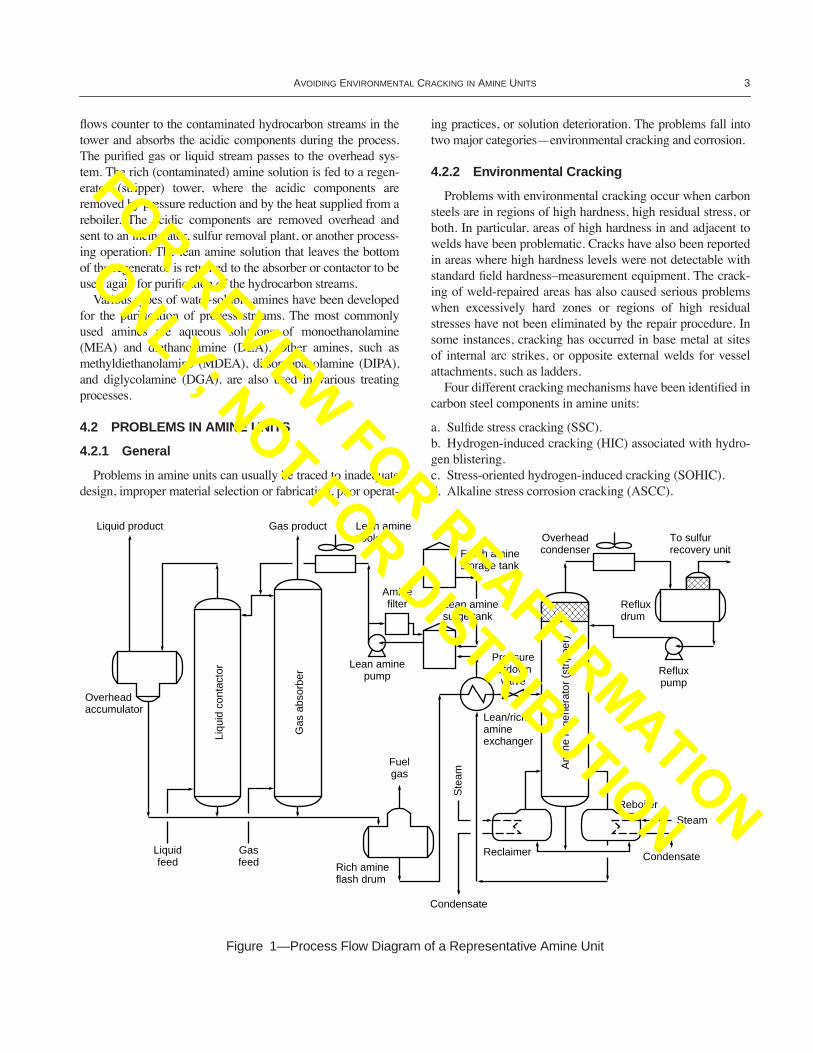
). Amine unitsoperating at low and high pressures are used to remove suchacidic components from process streams through contact with,and absorption by, an aqueous amine solution. Figure 1 is aprocess ßow diagram for a representative unit. The gas or liq-uid streams containing one or both of the acidic componentsare fed to the bottom of a gas-absorber tower or liquid-contac-tor vessel, respectively. The lean (regenerated) amine solution
1
NACE International, 1440 South Creek Drive, Houston, Texas77084-4906, www.nace.org.
2
American Society of Mechanical Engineers, 345 East 47th Street,New York, New York 10017, www.asme.org.
3
American Society for Testing and Materials, 100 Barr HarborDrive, West Conshohocken, Pennsylvania 19428, www.astm.org.
FOR REVIEW FOR REAFFIRMATION
ONLY; NOT FOR DISTRIBUTION
A
VOIDING
E
NVIRONMENTAL
C
RACKING
IN
A
MINE
U
NITS
3
ßows counter to the contaminated hydrocarbon streams in thetower and absorbs the acidic components during the process.The puriÞed gas or liquid stream passes to the overhead sys-tem. The rich (contaminated) amine solution is fed to a regen-erator (stripper) tower, where the acidic components areremoved by pressure reduction and by the heat supplied from areboiler. The acidic components are removed overhead andsent to an incinerator, sulfur removal plant, or another process-ing operation. The lean amine solution that leaves the bottomof the regenerator is returned to the absorber or contactor to beused again for puriÞcation of the hydrocarbon streams.
Various types of water-soluble amines have been developedfor the puriÞcation of process streams. The most commonlyused amines are aqueous solutions of monoethanolamine(MEA) and diethanolamine (DEA). Other amines, such asmethyldiethanolamine (MDEA), diisopropanolamine (DIPA),and diglycolamine (DGA), are also used in various treatingprocesses.
4.2 PROBLEMS IN AMINE UNITS
4.2.1 General
Problems in amine units can usually be traced to inadequatedesign, improper material selection or fabrication, poor operat-
ing practices, or solution deterioration. The problems fall intotwo major categoriesÑenvironmental cracking and corrosion.
4.2.2 Environmental Cracking
Problems with environmental cracking occur when carbonsteels are in regions of high hardness, high residual stress, orboth. In particular, areas of high hardness in and adjacent towelds have been problematic. Cracks have also been reportedin areas where high hardness levels were not detectable withstandard Þeld hardnessÐmeasurement equipment. The crack-ing of weld-repaired areas has also caused serious problemswhen excessively hard zones or regions of high residualstresses have not been eliminated by the repair procedure. Insome instances, cracking has occurred in base metal at sitesof internal arc strikes, or opposite external welds for vesselattachments, such as ladders.
Four different cracking mechanisms have been identiÞed incarbon steel components in amine units:
a. SulÞde stress cracking (SSC).b. Hydrogen-induced cracking (HIC) associated with hydro-gen blistering.c. Stress-oriented hydrogen-induced cracking (SOHIC).d. Alkaline stress corrosion cracking (ASCC).
Figure 1—Process Flow Diagram of a Representative Amine Unit
Liquid product Gas product Lean aminecooler Overhead
condenserTo sulfurrecovery unitFresh amine
storage tank
Lean aminesurge tank
Aminefilter
Lean aminepump
Refluxdrum
Pressureletdownvalve
Lean/richamineexchanger
Overheadaccumulator
Liqu
id c
onta
ctor
Gas
abs
orbe
r
Am
ine
rege
nera
tor
(str
ippe
r)
Refluxpump
Fuelgas
Ste
am
Condensate
Liquidfeed
Gasfeed Rich amine
flash drum
Reclaimer
Reboiler
Steam
Condensate
FOR REVIEW FOR REAFFIRMATION
ONLY; NOT FOR DISTRIBUTION

4 API R
ECOMMENDED
P
RACTICE
945
The Þrst three mechanisms are most prevalent in carbonsteels that have been exposed to rich amine solutions loadedwith H
2
S, including the lower sections of absorber or contac-tor towers. In contrast, ASCC is more common in carbonsteel components that have been exposed to lean amine ser-vice. Cracking can occur both with and without signiÞcantmetal loss. DeÞnitions of these cracking mechanisms andphotomicrographs are presented in Appendix A.
Several serious cracking problems have been reported overthe past 50 years. ASCC of carbon steel by amine solutions wasÞrst mentioned in a report published in 1951 by the NACETechnical Practices Committee 5C on Sub-Surface Corrosionby Alkaline Solutions [1]. The report noted that piping, regen-erators (strippers), absorbers, and heat exchanger shells andheads made from carbon steel had cracked after 6 months to 10years of exposure to 15-percent monoethanolamine in water(containing unspeciÞed amounts of both hydrogen sulÞde andcarbon dioxide) at temperatures up to 149¡C (300¡F). Com-plete stress relieving was recommended as a solution to theproblem.
In 1953, ASCC was reported in MEA solutions in gas treat-ment plants [2]. Requirements for cracking included the pres-ence of both a high stress and a particular corrosive aminesolution. The elimination of either factor was found to preventcracking. Recommended preventive measures included main-taining the reboiler temperature and the regenerator pressure atthe lowest practical levels, using reclaimers, and preventing aircontact to minimize the corrosiveness of the amine solutions.Frequently, such process changes cannot be readily imple-mented, so stress relieving was recommended as an effectivealternative to the recommended practices.
Other instances of ASCC were reported in non-stress-relieved equipment operating in 20-percent (by weight) mono-ethanolamine [3]. Affected equipment included two aminestorage tanks, four absorber towers, one rich amine ßash drum,one lean amine treater, and various piping. Cracking was foundprimarily at welds exposed to amine solutions where tempera-tures ranged from 53¡C to 93¡C (127¡F to 200¡F). The crack-ing was intergranular, and the crack surfaces were covered by athin Þlm of magnetite (Fe
3
O
4
). No cracking was found inpostweld heat treated (PWHT) piping that operated at tempera-tures as high as 154¡C (310¡F). Although the exact reason forthe extensive cracking was not clear, it was concluded thatPWHT could be used to prevent the problem.
A major problem occurred in 1984, when an MEAabsorber tower ruptured at a U.S. reÞnery. This failure initi-ated as SSC in the hardened area of the heat-affected zone ofa rewelded shell seam and propagated by SOHIC through thebase metal [4]. The weld repair had been performed 10 yearsearlier as part of a procedure to replace a shell course.
In 1986 extensive leaking of piping welds was reported inlean MEA service [5]. The leaking was attributed to ASCC.Most leaks occurred at piping welds that had been in leanamine service for 4 to 8 years. Cracks were found in the weld
deposits, heat-affected zones, and areas of the base metaladjacent to heat-affected zones. Typically, the cracks propa-gated parallel to the weld. Shear-wave ultrasonic inspectionconÞrmed the presence of cracks at many other welds in leanamine piping. None of the cracked piping welds had receivedPWHT.
As a result of these occurrences, in 1985 the NACE GroupCommittee T-8 on ReÞning Industry Corrosion, in coopera-tion with the API Subcommittee on Corrosion and Materials,sponsored an industry-wide survey of cracking problems inamine services [6]. The results of this survey indicated thatcracking was most prevalent in MEA service, and that itoccurred in all types of equipment at temperatures as low asambient. PWHT of welds was identiÞed as the single mosteffective means of preventing cracking. Additional data onstress corrosion cracking of carbon steel in DEA and DIPAservices were reported in 1991 [7] and in DEA, DIPA, andMDEA service in 1993 [8].
4.2.3 Corrosion
Corrosion (metal loss) of carbon steel components inamine units is not caused by the amines themselves. It usuallyresults from dissolved acid gases, including hydrogen sulÞdeand carbon dioxide. Corrosion can also be caused by a varietyof amine degradation products including heat stable salts. Thecracking of carbon steel components in amine service is oftenrelated to the general corrosivity of amine solutions. Corro-sion reactions are the source of atomic hydrogen, whichcauses hydrogen blistering and cracking by mechanisms suchas SSC, HIC, and SOHIC, primarily of components in richamine service (see Appendix A). Similarly, corrosion reac-tions can contribute to ASCC, primarily of equipment in leanamine service. It is not possible, however, to quantitativelyrelate cracking severity to corrosion severity. Nevertheless,efforts aimed at improving corrosion control may also reducehydrogen-related cracking. (See Appendix B for more infor-mation regarding corrosion in amine units.)
5 Guidelines for Construction Materials and Fabrication of New Equipment
5.1 CONSTRUCTION MATERIALS
Carbon steel, with a nominal corrosion allowance, hasbeen used for most equipment in amine units that removehydrogen sulÞde or mixtures of hydrogen sulÞde and carbondioxide containing at least 5 percent hydrogen sulÞde. Someproblems have been experienced with erosion-corrosion (seeB.3 and B.6.2) associated with circumferential welds in richamine piping made of carbon steel. The problems weresolved by reducing ßuid velocity to less than 1.8 m/sec (6 ft/sec). Austenitic stainless steels have been used in locationswhere the corrosion rate of carbon steel is excessive. Suchlocations include those that contact hot/rich solutions with
FOR REVIEW FOR REAFFIRMATION
ONLY; NOT FOR DISTRIBUTION
A
VOIDING
E
NVIRONMENTAL
C
RACKING
IN
A
MINE
U
NITS
5
high acid gas loading, areas of high velocity, turbulence,impingement, vapor ßashing, or two-phase ßow, and mostheat transfer surfaces operating above approximately 110¡C(230¡F). Austenitic stainless steels are usually employedextensively in amine units to remove carbon dioxide fromhydrocarbon streams that contain very little or no hydrogensulÞde. Clad plate is preferred over solid stainless steel con-struction to avoid possible through-wall penetration thatresults from chloride stress corrosion cracking. In some loca-tions, solid stainless steel construction was used where con-trol of external chloride stress corrosion cracking wasachieved. Alloys, such as Types 304 and 316, have been usedfor regenerator reboiler tubes that handle little or no hydrogensulÞde. Titanium tubes have been used in units handling CO
2
,but they may hydride in service.
Carbon steels with a low level of inclusions, inclusionshape control, or both may provide improved resistance tohydrogen blistering, HIC, and SOHIC. These steels should beevaluated for potential use in equipment that handles richamine solutions, and in the regenerator overhead, especially ifcyanides are present. In some units, operating conditions inthe bottom of amine absorbers or contactors are conducive tohydrogen damage despite relatively low temperatures. Car-bon steels with a low level of inclusions or inclusion shapecontrol might also be useful in these locations. However, itshould be noted that these steels are not immune to blisteringand cracking, so their potential use should be carefully con-sidered. It should also be noted that continuous cast steelsmay be low in inclusion content, but impurities that arepresent might segregate at the plate mid-wall, which cancause high hardness or laminations at that location. Austeniticstainless steel cladding, lining, or weld overlay can offeralternative methods of protection in areas where chroniccracking or hydrogen blistering occurs.
5.2 FABRICATION
5.2.1 General
Certain fabrication practices can help reduce the likelihoodof cracking in carbon steels in amine units. These practicesinclude controlling weldment hardness levels and applyingPWHT. Attention should be given to proper base metal andweld composition to assure satisfactory response to heat treat-ment. To control cracking problems effectively proper consid-eration should be given to each of these factors. Refer to APIRP 582 for guidance on weld fabrication.
5.2.2 Weldment Hardness Control
Proper control of weldment hardness in fabricated carbonsteel equipment can provide resistance to SSC. NACE RP0472
deÞnes practical and economical means of protection againstthis type of cracking, and outlines necessary controls on basemetal, weld composition, and welding parameters to achieveweldments of acceptable hardness for the intended service.
As stated in NACE RP0472, the weld hardness of carbonsteel equipment, including piping, should not exceed aBrinell hardness of 200, unless the purchaser has agreed to ahigher allowable hardness.
However, it should be noted that a maximum Brinell hard-ness of 200 in the weld deposit provides no assurance of pre-venting SSC in the weldÕs heat-affected zone, or in base platematerial where temporary attachments have been made or arcstrikes have occurred. Other measures outlined in RP0472,including PWHT, should therefore be considered as a meansof providing added cracking resistance to carbon steel weld-ments. In the case of amine systems handling CO
2
only, theredoes not appear to be any beneÞt to limiting weldment hard-ness to 200 HB. Hardness limits for such systems should beevaluated by each user based on past experience.
As noted in Section A.5 controlling weldment hardness hasno known effect on the prevention of ASCC. However,PWHT can reduce residual stress in carbon steel weldments,thereby effectively controlling ASCC.
5.2.3 Postweld Heat Treatment
5.2.3.1 General
PWHT is an effective method for improving the crackingresistance of carbon steel weldments in amine service. Aneffective procedure consists of heating to 593¡C Ð 649¡C(1100¡F Ð 1200¡F) and holding in this temperature range for1 hour per 25 mm (1 in.) of metal thickness, or fractionthereof, with a 1-hour minimum holding time. PWHT below593¡C (1100¡F) is not considered effective for crack preven-tion; therefore, it is not recommended. It should be noted thatthe allowable variation in the chemical composition of steelscan be considerable, even within the same grade. In conjunc-tion with welding variables, this can produce high hardnessesin heat-affected zones that might not be adequately softenedby normal PWHT. Each situation should be evaluated todetermine whether the proposed PWHT is adequate.
Investigations have shown that inadequate heated bandwidth can result in residual stresses of up to 172 MPa (25 ksi)after heat treatment. The residual stresses are highest withlarge diameter piping, due to higher internal convection andgreater dispersion of radiated heat from the pipe ID. The fol-lowing guidelines have been provided to minimize residualstresses, and may be used to increase resistance to SSC,SOHIC, and ASCC.
FOR REVIEW FOR REAFFIRMATION
ONLY; NOT FOR DISTRIBUTION

6 API R
ECOMMENDED
P
RACTICE
945
a. The minimum heated band width should be as follows:
Where:
BW
= Heated Band Width
R
= Pipe Radius (Outside Diameter)
t
= Pipe Wall Thickness
b. Insulate over the total heated band width and a 230 mm (9in.) minimum runout on both sides, using at least 50 mm (2 in.)thick insulation blankets.c. In the case of ßange welds, insulate the entire ßange insideand out, and a 230 mm (9 in.) runout of the pipe side of the weld. d. If possible, close off the ends of the pipe to minimize con-vection currents.
PWHT should be applied to new carbon steel equipment,including piping in amine services, as described in 5.2.3.2through 5.2.3.6.
5.2.3.2 MEA Units
For MEA units, PWHT is recommended for all carbonsteel equipment, including piping, regardless of service tem-perature. Cracking has been quite prevalent in non-PWHTcarbon steel equipment at all normal operating temperatures.
5.2.3.3 DEA Units
For DEA units, PWHT is recommended for all carbon steelequipment, including piping, exposed to amine at servicetemperatures of 60¡C (140¡F) and higher. The maximumoperating temperature and the effects of heat tracing andsteam-out on the metal temperature of components in contactwith the amine should be considered.
Industry experience has shown that many reportedinstances of ASCC in DEA units have occurred in non-PWHT carbon steel equipment exposed to temperatureshigher than 60¡C (140¡F). However, some cracking problemshave been reported in DEA units at temperatures below thisvalue. In some cases, equipment, including piping, has beenknown to crack during steam-out due to the presence ofamine [7]. Each user company should evaluate the need for
PWHT of carbon steel at temperatures below 60¡C (140¡F),especially for equipment such as absorbers and contactors.
5.2.3.4 DIPA Units
For DIPA units, PWHT is recommended for all carbonsteel equipment, including piping, regardless of service tem-perature. Cracking has been prevalent in non-PWHT carbonsteel equipment at all normal operating temperatures exposedto 15 to 20 percent DIPA solutions [7]. This guideline doesnot apply to units containing a mixture of sulfolane andhigher concentration DIPA (typically 50 percent), where nocracking has been reported.
5.2.3.5 MDEA Units
For MDEA units, PWHT is recommended for all carbonsteel equipment, including piping, exposed to amine at ser-vice temperatures of 82¡C (180¡F) and higher. The maximumoperating temperature and the effects of heat tracing andsteam-out on the metal temperature of components in contactwith the amine should be considered.
Industry experience has shown that cracking has not beenprevalent in MDEA units. Only a few instances of crackinghave been reported to date, and all but one of these occurredin equipment exposed to temperatures higher than 88¡C(190¡F) [8].
5.2.3.6 Other Amine Units
In amine units other than MEA, DEA, DIPA, and MDEA,experience suggests that susceptibility to cracking is verylow, especially at temperatures below 88¡C (190¡F). It seemsthat cracking susceptibility generally decreases in the order ofprimary amine, secondary amine, and tertiary amine. There-fore, each user company must evaluate the need for PWHT ofcarbon steel in such units. For licensed amine treating pro-cesses, the licenser should provide the operating companywith guidance on PWHT requirements, based on laboratorytesting, actual experience in other licensed plants, or both.
The cracking tendencies of amine solutions can be deter-mined by careful inspection of operating facilities that are inactual amine service; appropriate laboratory tests can also bebeneÞcial. Slow strain rate testing is a useful laboratorymethod to establish the tendency of amine solutions to pro-mote cracking [5, 9, 10]. However, the test may provide con-servative data; that is, it may indicate a tendency for stresscorrosion cracking where it does not occur in actual service.If this test procedure is used, the test solutions should containthe acid gases (hydrogen sulÞde and carbon dioxide) andother anticipated stream contaminants found in operatingplants; where it is possible, tests should be conducted usingactual plant solutions.
NominalPipe Size
Minimum Heated Band Width
19 to 25 mm (
3
/
4
to 1 in.) 102 mm (4 in.)38 to 76 mm (1
1
/
2
to 3 in.) 152 mm (6 in.)102 to 152 mm (4 to 6 in.) 203 mm (8 in.)
³
203 mm (8 in.)
BW
= 4.12 (
Rt
)
1/2 + 50.8 mm(203-mm minimum)[BW = 4.12 (Rt)1/2 + 2 in.](8-in. minimum)
FOR REVIEW FOR REAFFIRMATION
ONLY; NOT FOR DISTRIBUTION

AVOIDING ENVIRONMENTAL CRACKING IN AMINE UNITS 7
5.2.4 Socket-Welded Connections
Small-diameter socket-welded connections can containgeometrical discontinuities that act as local stress raiserswhere cracks may initiate. Where PWHT is recommended forcarbon steel equipment or piping containing socket-weldedconnections, the connections should also receive PWHT.
5.2.5 Threaded Connections
Threaded connections may contain highly stressed threadroots that can serve as crack initiation points in amine service.The use of threaded connections should be carefully evalu-ated in amine service where PWHT of carbon steel welds isrequired to resist cracking.
6 Inspection and Repair of Existing Equipment
6.1 GENERAL
6.1.1 General Guidelines
The procedures in this section are guidelines for theinspection and repair of existing equipment used to handleamines. The objective is to maintain such equipment in a safeand reliable condition.
The examinations listed in this section emphasize inspec-tion of equipment for cracks. Inspection should be in accor-dance with API 510 and API 570.
Inspection of equipment in amine service should be con-ducted or supervised by experienced, certiÞed inspectors whohave comprehensive knowledge of the speciÞc unit, its mate-rials of construction, and its operating, maintenance, andinspection history.
6.1.2 Use
The procedures discussed in this section have been foundto be effective in the inspection of amine unit equipment, butthey are not the only means of achieving the desired inspec-tion. New instrumentation and procedures are under develop-ment and should be evaluated as they become available.
6.1.3 Intent
This document is a recommended practice; therefore, noneof the inspection methods or recommendations in this docu-ment are mandatory. Procedures that differ from governmentregulations (local or otherwise) should be evaluated carefullyto conÞrm their compliance with such requirements. In areaswhere these procedures are superseded by jurisdictional regu-lations, those regulations shall govern. The responsibility foridentifying and complying with legislative requirements restswith the user company.
6.1.4 Safety
Before entry, API Publication 2217A Guidelines for Workin Inert Confined Spaces in the Petroleum Industry should beconsulted.
6.2 INSPECTION INTERVALS
The priority of equipment examination should consider theconsequences of a leak or a failure on the surrounding area,operating conditions (temperatures, pressure, and contents),criticality of the equipment, and inspection and repair history.A methodology for a risk-based approach is outlined in APIRP 580.
6.2.1 Initial Inspection
An initial examination should be made of any susceptible,non-PWHT equipment listed in 6.3. High priority equipmentshould be inspected by internal wet ßuorescent magnetic par-ticle testing (WFMT: see 6.4.1) at the next scheduled shut-down. A partial inspection of representative weldments withapproximately 20 percent coverage may be performed Þrst.Additional WFMT should be performed if cracking isdetected by this initial examination.
If hydrogen blisters are identiÞed during an internal visualinspection, consideration should be given to performing aselective ultrasonic (longitudinal) inspection to identify blis-tered areas not apparent by visual inspection. Blistered areasshould be further examined to determine if HIC and SOHICare present.
External ultrasonic shear-wave examination may be per-formed while the equipment is on stream. If the externalinspection reveals cracking, or if the inspection history indi-cates past problems, the need for additional on-stream inspec-tion, or the need for and timing of an internal inspection byWFMT, should be evaluated. In any case, an initial internalinspection for cracks in non-PWHT equipment should bemade.
The maintenance and inspection records of PWHT equip-ment should be checked for past problems. Welds made on theequipment that have not received PWHT should also beinspected. This information should be used to determine thenext date for internal and/or on-stream inspection for cracking.
Piping that has not received PWHT should also be consid-ered for inspection. External inspection procedures, such asthose listed for stationary equipment, should be applied topiping. Internal inspection of small diameter piping may beimpractical (see 6.3.2). The user company must determinewhether external inspection is sufÞcient to satisfy the criteriafor safe operation.
6.2.2 Reinspection of Repaired Equipment
Equipment listed in 6.3 that has been repaired in accordancewith 6.5 and 6.6, and that has not received PWHT, should be
FOR REVIEW FOR REAFFIRMATION
ONLY; NOT FOR DISTRIBUTION

8 API RECOMMENDED PRACTICE 945
considered for reinspection during the next scheduled shut-down. An examination should be performed as described in 6.4and should primarily include weld repair areas, as well as spotchecks of previously noted sound material.
6.2.3 Reinspection of Undamaged Equipment
Reinspection should be conducted at appropriate intervalson any of the equipment listed in 6.3 that has been found to beundamaged during previous inspection. The intervals can beset by experience, equipment criticality, and whether or notthe equipment has received PWHT. Reinspection shouldinclude the examination of randomly selected areas. Rein-spection intervals should be reevaluated if signiÞcant processchanges occur, such as amine type, amine solution composi-tion, ßow rate increases and/or temperature increases.
6.3 EQUIPMENT AND PIPING THAT SHOULD BE INSPECTED
6.3.1 Equipment
Common equipment that should be considered for inspec-tion includes: absorbers, accumulators, coalescers, columns,condensers, coolers, contactors, extractors, Þlter vessels, ßashdrums, heat exchanger shells/channels/tube bundles, knock-out drums, reactivators, reboilers, reclaimers, regenerators,scrubbers, separators, settlers, skimmers, sour gas drums,stills, strippers, surge tanks, treating towers, and treated fuelgas drums.
Inspection of welded pressure-containing equipment asso-ciated with air coolers, such as header boxes, should be con-sidered. Pump cases in amine service that have had weldrepairs should be inspected for the presence of cracks.
SpeciÞc areas for inspection include those in and adjacentto longitudinal and circumferential welds; manway and noz-zle attachment welds (including welds that attach reinforcingpads); attachment welds of internals (tray and downcomerwelds, support attachment welds for distributors and vortexeliminators); areas repaired by welding; heat-affected zoneson internal surfaces opposite externally attached structuralsteel platforms, ladders, and the like; and arc strikes. Theweld areas behind, or associated with, leaking panels of alloystrip-lined vessels should also be inspected.
Cracks and related defects initiate internally. Therefore, theprimary inspection effort should be directed toward internalsurfaces contacted by amine solutions.
6.3.2 Piping
All process piping associated with amine units that havenot been postweld heat treated should be considered forinspection to detect cracking. It might be more economical toreplace small diameter piping than it is to inspect it, and this
alternative should be evaluated. SpeciÞc areas to be inspectedinclude those in and adjacent to the following locations:
a. Welds of pressure-containing piping.b. Attachment welds associated with pipe shoes, supportclips, or other non-pressure-containing attachments.c. Weld arc strikes found on pipes.d. Attachment welds of reinforcing pads for nozzles.e. Repair welds of any type.
Stress corrosion cracks and related defects initiate inter-nally. Therefore, the inspection should be directed towardinternal surfaces that are contacted by amine solutions.
The following methods are useful for the external nonde-structive inspection of piping:
a. Ultrasonic testing (see 6.4.3).b. Radiographic testing (see 6.4.4).c. Visual examination (see 6.4.6).
At times, it may be appropriate to remove selected pipesegments, cut them in half longitudinally, and use WFMT toinspect their internal surfaces.
6.4 EXAMINATION PROCEDURES AND METHODS
6.4.1 Wet Fluorescent Magnetic Particle Testing
Wet ßuorescent magnetic particle testing (WFMT) is avery sensitive method for detecting surface-connected cracksand discontinuities. WFMT using an AC yoke is one of theprimary methods recommended for internal inspection ofpressure vessels in amine service.
Two modes of operation are available for the magnetizing -AC yoke and half-wave DC prods. The AC yoke modeachieves greater sensitivity in locating surface defects, andalso reduces the effects of background interference. For thesereasons, it is the recommended mode. The half-wave DCmode offers improved penetration of the magnetic Þeld intothe area that is being inspected, thereby permitting the detec-tion of near surface defects in addition to surface defects.However, use of DC prods is not recommended because theycan induce arc burns that could initiate future cracking.
WFMT requires surfaces that are cleaned to a near-whiteÞnish that meets the requirements of NACE No. 2/SSPC SP10. Abrasive blasting or high-pressure waterjetting at a pres-sure of 70 MPa (10,000 psig) or higher may be used. Thearea prepared for inspection should normally be 100 Ð 150mm (4 Ð 6 in.) on either side of the weld. However, the sizeof the area may vary depending on the location of arc strikes,exterior welds, and the like. The entire internal surface doesnot have to be prepared for inspection. Residual abrasivematerial and debris should be removed from the equipmentbefore inspection.
Light grinding may be needed to distinguish anomalies inweld proÞles from indications of discontinuities, e.g., at thetoe of welds.
FOR REVIEW FOR REAFFIRMATION
ONLY; NOT FOR DISTRIBUTION

AVOIDING ENVIRONMENTAL CRACKING IN AMINE UNITS 9
Extensive Þeld experience has demonstrated that detectionof the Þne amine cracks is greatly enhanced by subsequentpolishing of the cleaned surfaces with ßapper wheels or ßexi-ble abrasive sanding pads. This polishing should be per-formed on at least a representative percentage of the cleanedsurface area in each piece of equipment, especially those withhigh priority.
Considerable Þeld experience has demonstrated that powerwire brushing of the areas to be inspected in lieu of the sur-face preparation methods recommended above does not pro-duce an acceptable surface for reliable detection of crackingin amine equipment, and therefore should not be used. Met-allographic inspection indicates that power wire brushingsmears metal on the surface that covers underlying cracking,greatly reducing the likelihood of its detection by WFMT.
6.4.2 Alternating Current Field Measurement
Alternating current Þeld measurement (ACFM) is an elec-tromagnetic technique that can be used to detect and size sur-face-breaking cracks in ferromagnetic materials. The methodcan be applied through thin coating and does not requireextensive surface preparation. It is best used as a screeningtool for rapid detection of cracking along welds and/or heat-affected zones with little or no surface preparation. It can beused in lieu of WFMT. The sensitivity of ACFM to cracksdecreases with the increase of the coating thickness and loosescale on the examination surface. ACFM can size cracklength reliably. It can also accurately assess depths of non-branched, though-wall-oriented cracks. However, its crackdepth sizing can yield erroneous results when ACFM isapplied on high-branched, closely-spaced, or tilted (i.e. notexactly in the through-wall direction) cracks, such as aminestress corrosion cracks. ACFM data interpretation is muchmore complicated than WFMT. Highly skilled, experiencedoperators are essential to the success of ACFM inspection.
6.4.3 Ultrasonic Testing
Ultrasonic testing (UT), using either manual or automatedmethods, is very useful for crack detection in amine equip-ment. UT methods include longitudinal, shear wave, andcrack-tip diffraction. Various UT methods can be used fordetecting and sizing subsurface-connected cracks larger thanapproximately 3 mm (0.125 in.). Longitudinal UT is usefulfor evaluating in-plane cracking, such as hydrogen blistering.Shear wave UT is useful for evaluating through-thicknesscracking, such as SSC, HIC, SOHIC, and ASCC. UT meth-ods are non-intrusive, thereby facilitating inspection of equip-ment and piping from the external surface. Depending on thesurface temperature limitations, UT inspection can be per-formed onstream.
UT will reveal discontinuities in welds. However, theeffective use of this inspection method depends highly on theUT operatorÕs knowledge, skill, and experience levels. Small,
tight cracks might be overlooked by an inexperienced opera-tor, or the cracks might be so tight or shallow that their UTsignals are not easily identiÞed.
Welds not fabricated in conjunction with a 100-percentweld quality inspection program might exhibit indications ofdiscontinuities when examined by UT. This can result in hav-ing to evaluate minor weld discontinuities that may be of noconsequence to vessel integrity.
UT is a valuable tool for inspecting operating equipment. Ifthe limitations of the method are understood, inspections canbe used to ensure continued safe operation of equipmentwithout costly shutdowns.
6.4.4 Radiographic Testing
Radiographic testing (RT) is sometimes employed to detectcracks in amine equipment. However, unless the cracks arereasonably large or severe, radiographic inspection is not avery sensitive inspection method. This does not mean thatradiographic inspection should be avoided; the method canreveal major defects relatively quickly, but if weld cracks aredetected, a more extensive examination by UT should be con-sidered. RT is a tool with limited applicability for inspectingpiping in operation as ßow characteristics might affect thequality of the radiographs.
6.4.5 Liquid Penetrant Testing
Liquid penetrant testing (PT) is not a recommended inspec-tion method because it does not reliably reveal the tight Þs-sures that are characteristic of cracking in amine equipment.
6.4.6 Visual Examination
Visual examination of operating equipment in accordancewith API 510 and API 570 should be part of the inspectionprocess. Visual examination of uninsulated piping and vesselsthat are in operation can detect leaks at welds and otherpotential problem areas. The presence of a bubble in the paintover a weld, adjacent to a weld, or at any other area should beconsidered suspicious, because it can indicate the location ofan extremely tight crack. Such cracks could weep and cause abubble. An active, dripping leak obviously indicates a prob-lem that warrants immediate attention.
6.4.7 Surface Preparation—General
All methods of inspection rely on a level of surface prepa-ration to facilitate the reliable detection of cracking. Thedegree of surface preparation may vary considerably depend-ing on the inspection technique that will be applied. Inade-quate surface preparation can seriously reduce theeffectiveness of any inspection technique.
Equipment should be thoroughly cleaned before internalinspections are performed. Amines are water soluble, andcopious amounts of water should be used to wash the surfaces
FOR REVIEW FOR REAFFIRMATION
ONLY; NOT FOR DISTRIBUTION

10 API RECOMMENDED PRACTICE 945
and remove any residual amine contamination. As noted in5.2.3.3, some equipment has cracked during steam-out due tothe presence of amine. Therefore, if steam-out is required forequipment cleaning, it should follow a thorough water washto remove any residual amine. The equipment should be driedand loose scale, fouling deposits, and other material removedfrom all surfaces.
Limited laboratory data and Þeld experience have indicatedthat in wet H2S services, removal of protective scales fromthe internal surfaces of equipment by surface preparation tofacilitate internal inspection might increase the likelihood ofcracking when the equipment is returned to operation. Thisphenomenon is expected to be dependent upon the severity ofthe environment, speciÞc start-up conditions, and the crack-ing susceptibility of the base metal or weldment. Recentresearch conducted using a large-scale pressure vesselexposed to severe hydrogen charging conditions has con-Þrmed that this is a viable concern [11]. Removal of the nor-mally protective Þlms on the steel surfaces led to a shortperiod of higher-than-normal hydrogen ßux during simulatedstart-up conditions and produced increased cracking that wasconÞrmed by acoustic emission testing (AET), UT, and post-test metallographic sectioning of the test vessel. Use of cer-tain inhibitors applied directly to the cleaned surfaces afterinspection was found to minimize the levels of hydrogen ßuxduring simulated start-up conditions. Coatings, while notspeciÞcally addressed in this research work, may also be asuitable mitigation method. Notwithstanding the results ofthis research, industry experience has not indicated that sur-face preparation has subsequently led to signiÞcant additionalcracking, especially in amine service.
6.5 REPAIR OF DAMAGED EQUIPMENT
6.5.1 General
The repair methods listed in 6.5.2 and 6.5.3 primarilyapply to equipment and large diameter piping. Small diameterpiping [50 mm (2 in.) and smaller] can usually be replacedwith new PWHT components at a lower cost than in siturepair and heat treatment.
6.5.2 Crack Removal by Grinding and Gouging
For all repairs, amine residuals and contaminants should beremoved from equipment surfaces prior to grinding, gouging,welding, and PWHT. Flushing with copious amounts of wateris usually effective; in some cases additional cleaning with aninhibited acid solution, followed by water ßushing, isrequired. Caution needs to be exercised when acid cleaningsulÞde scales because of potential H2S release.
Careful grinding is the preferred method for removingcracks and other discontinuities. The procedure requires care-ful control to avoid defect growth. During the grinding proce-
dure, the area in question should be periodically checked(preferably by WFMT) to assure that all defects are eliminated.
Flame gouging and arc gouging (if used) must be per-formed with care, since these procedures may also cause thedefects to increase in size. These methods can be used effec-tively as the Þrst stage of crack removal. This should be fol-lowed by grinding and periodic WFMT to check for defectremoval as discussed above.
If the defect depth is less than the corrosion allowance, anacceptable repair could consist of removing the defect bygrinding, and feathering, or contouring the edges of the grind-out area by removing sharp edges and providing a smoothtransition to the surrounding surface. Welding may not benecessary when this repair method is used.
If the defect depth is greater than the corrosion allowance,the evaluation and Þtness-for-service methods methods speci-Þed in API 510, API 570 and RP 579, should be used to deter-mine whether the vessel or piping with the locally thinnedarea is Þt for continued service.
6.5.3 Crack Repair by Welding
Prior to any welding, consideration should be given to theneed to remove (outgas) residual atomic hydrogen from thearea to be welded. This is most likely for equipment in richamine service that has been subjected to a signiÞcant level ofcorrosion and hydrogen charging. Outgassing should not beneeded for equipment in lean amine service. An acceptableoutgas procedure consists of heating the area to a metal tem-perature of 232¡C Ð 316¡C (450¡ Ð 600¡F) and holding thattemperature for 2 to 4 hours. Other similar procedures havealso been used effectively.
The area to be weld repaired should be preheated asrequired (see API 510 and RP 582). When all repairs are com-pleted, repaired areas should be examined using the samenondestructive test method that was initially selected (prefer-ably WFMT). Other methods may be used to supplement theexamination of the repairs as desired.
6.6 POSTWELD HEAT TREATMENT OF UNDAMAGED OR REPAIRED EQUIPMENT
After existing amine equipment has been thoroughlyinspected, consideration should be given to performing astress-relieving heat treatment. If there is no history of crack-ing problems, and if thorough inspection has revealed no evi-dence of cracking in the equipment, heat treatment might notbe warranted. However, PWHT is considered essential if anyweld repairs are performed on equipment that originallyreceived PWHT. If weld repairs are performed on equipmentthat did not originally receive PWHT, PWHT of repairedwelds should be considered by using the guidelines in 5.2.3.PWHT is strongly advised for certain replacement equipment(see 5.2.3) and for any equipment that has a prior history ofcracking.
FOR REVIEW FOR REAFFIRMATION
ONLY; NOT FOR DISTRIBUTION

AVOIDING ENVIRONMENTAL CRACKING IN AMINE UNITS 11
The decision to heat treat must be made by each user com-pany after the speciÞc situation has been thoroughly evalu-ated. Factors of consideration should include, but are notlimited to, personnel and equipment safety, age and conditionof the unit, cost of heat treatment versus equipment replace-ment, and the intended frequency of future inspections. For insitu PWHT, the equipment and supporting structures must beevaluated to determine and assure their ability to withstandthe heat treatment temperatures without permanent distortionor damage. All such evaluations must be based on a thoroughunderstanding of the requirements of any codes, standards, orlaws governing the operation of such equipment.
Equipment should Þrst be washed and thoroughly cleanedbefore heat treatment is performed. Cleaning should includeßushing with copious amounts of water. All residual amine
must be removed from the equipment before heat treatment.After the equipment has been properly cleaned heat treatmentmay proceed. The procedure should be as speciÞed in 5.2.3.Alternative heat treatments at temperatures below 593¡C(1100¡F) should not be performed.
After heat treatment has been completed, the equipmentshould be carefully inspected again, by one of the acceptablemethods. If no defects are found, the equipment may bereturned to service. If defects are found after heat treatment, itmust be decided if the equipment should be recleaned,repaired, or re-heat treated. In some cases it might be moreeconomical to permanently remove the defective equipmentfrom service and replace it with a new component that hasreceived PWHT.
FOR REVIEW FOR REAFFIRMATION
ONLY; NOT FOR DISTRIBUTION

FOR REVIEW FOR REAFFIRMATION
ONLY; NOT FOR DISTRIBUTION

13
APPENDIX A—CRACKING MECHANISMS
A.1 General
There are four basic cracking mechanisms that can affectcarbon steel equipment in amine units. Three of these,namely sulÞde stress cracking, hydrogen-induced cracking,and stress-oriented hydrogen-induced cracking, are forms ofhydrogen-related damage. These forms of hydrogen-relateddamage are typically associated with the entry of atomichydrogen into the steel. The atomic hydrogen is generated onthe steel surface by a corrosion reaction. In amine systems,the corrosion of steel by hydrogen sulÞde in an aqueous envi-ronment is usually responsible for hydrogen entry into thesteel. The fourth type of cracking that can occur in amine sys-tems is alkaline stress corrosion cracking. This is a form ofanodic stress corrosion cracking, and is not related to thethree forms of hydrogen-related damage. The basic crackingmechanisms and methods for minimizing their occurrence inamine systems are discussed in the following sections.
A.2 Sulfide Stress Cracking
SSC is deÞned as the cracking of a metal under the com-bined action of tensile stress and corrosion in the presence ofwater and hydrogen sulÞde. It is a form of hydrogen stresscracking (HSC). Corrosion of the steel by the hydrogen sulÞdeliberates atomic hydrogen at the metal surface. The hydrogensulÞde also poisons the recombination of the atomic hydrogeninto molecular hydrogen, thus promoting the absorption ofatomic hydrogen by the steel. The atomic hydrogen then dif-fuses through the steel and tends to accumulate at areas ofhigh metal hardness and high tensile stress (either applied orresidual) and embrittles the steel. Therefore, the SSC mecha-nism involves hydrogen embrittlement. The cracking mode isprimarily transgranular in lower strength steels, but can bemixed mode or even intergranular in localized hard regionsand in higher-strength (i.e., martensitic or bainitic) steels. Fig-ure A-1 illustrates a sulÞde stress crack that initiated in a hardheat-affected zone of a steel weldment.
High metal hardnesses are primarily found in the welddeposit and weld heat-affected zones in the adjacent basemetal. Hardness levels in these regions depend on the compo-sition of the steel (i.e., weld deposit and base metal), strengthlevel, and the welding and postweld heat-treating procedurethat is employed. The hardness level of a weldment must becontrolled below certain maximum values to minimize thelikelihood of SSC [12].
High metal stresses of concern are primarily localizedstresses from residual welding stresses and poor weld jointÞt-up. The threshold stress for cracking and the severity ofSSC is inßuenced substantially by the concentration ofatomic hydrogen in the steel. The atomic hydrogen ßux thatpermeates the steel is related to the level of corrosion activity
at the steel surface, which is primarily a function of hydrogensulÞde concentration and pH of the aqueous solution. Othersolution contaminants can inßuence the corrosion activity andhydrogen entry into the steel. The hydrogen ßux is normallyat its minimum in near neutral pH solutions and increasessubstantially at lower and higher pH values.
SSC can be minimized by limiting weldment hardness andby applying proper PWHT (see 5.2). SSC may be mitigated,but not prevented, through use of effective corrosion controlprocedures that reduce the rate of sulÞde corrosion andhydrogen charging of the steel (see Appendix B). Addition-ally, the likelihood of cracking during a weld repair of post-service equipment can be reduced by outgassing the weld-ment (see 6.5.3).
A.3 Hydrogen-Induced Cracking Associated With Hydrogen Blistering
Hydrogen blistering is deÞned as the formation of subsur-face planar cavities, called hydrogen blisters, in a metalresulting from excessive internal hydrogen pressure. Growthof near-surface blisters in low-strength metals usually resultsin surface bulges. Hydrogen blisters form in carbon steelswhen atomic hydrogen, generated by corrosion of the steelsurface, enters the steel and diffuses to voids, laminations,and other internal discontinuities, such as at nonmetallicinclusions, where it collects as molecular hydrogen. FigureA-2 illustrates hydrogen blisters near the ID surface of a car-bon steel ßange. Steels with higher impurity levels, whichtend to concentrate along planes parallel to the rolling direc-
Note: Two-percent nital etch at 30X magniÞcation.
Figure A-1—Sulfide Stress Cracking in an Existing Hardened Heat-Affected Zone of a Weld
FOR REVIEW FOR REAFFIRMATION
ONLY; NOT FOR DISTRIBUTION

14 API RECOMMENDED PRACTICE 945
tion of the plate, tend to experience more hydrogen blistering.As the internal pressure of molecular hydrogen increases,high stresses at the circumference of the blister can result inplastic deformation of the surrounding area. This might causethe blister to expand within its plane or, alternatively, mightcause HIC.
HIC is deÞned as stepwise internal cracks that connectadjacent hydrogen blisters on different planes in the metal, orto the metal surface. No externally applied stress is needed forthe formation of HIC. The driving force for the crack propa-gation is high stresses at the circumference of the blisters thatare caused by the buildup of internal pressure in the blisters.Interaction between these high stress Þelds tends to causecracks to develop that link blisters on different planes. Thelink-up of blisters on different planes in steels has beenreferred to as stepwise cracking to characterize the nature of
Note: Two-percent nital etch at 4.5X magniÞcation.
Figure A-2—Hydrogen Blisters near the ID Surface of a Carbon Steel Flange
Note: Two-percent nital etch at 5.5X magniÞcation.
Figure A-3—Stepwise Hydrogen-Induced Cracking (HIC) in a Carbon Steel Specimen
Note: The top panel is a two-percent nital etch at 2X magniÞcation.The bottom panel is a higher magniÞcation view of the crack tipshown in the top panel (two-percent nital etch at 200X magniÞcation).
Figure A-4—Stress-Oriented Hydrogen-Induced Cracking
FOR REVIEW FOR REAFFIRMATION
ONLY; NOT FOR DISTRIBUTION

AVOIDING ENVIRONMENTAL CRACKING IN AMINE UNITS 15
the crack appearance. Figure A-3 shows typical HIC damagein carbon steel.
Blistering and HIC can be minimized by selecting a higherquality steel (often referred to as a clean steel) with low inclu-sion content. Increased resistance to blistering and HIC is usu-ally achieved by lowering the sulfur content of the steel andcontrolling the sulÞde inclusion morphology by calcium orrare earth metal additions to produce spheroidal sulÞde shape.Base metal heat treatments, such as normalizing or quenching,and tempering above 593¡C (1100¡F), increase resistance toHIC. Using corrosion control procedures to reduce the sulÞdecorrosion and hydrogen charging also reduces the likelihoodof blistering and HIC. Stress reduction by PWHT has no sig-niÞcant impact on reducing blistering and HIC.
A.4 Stress-Oriented Hydrogen-Induced Cracking
SOHIC is deÞned as a stacked array of small blisters joinedby hydrogen-induced cracking, aligned in the through-thick-ness direction of the steel as a result of high localized tensilestresses. SOHIC is a special form of HIC that usually occursin the base metal, adjacent to the heat-affected zone of a weld,where there are high residual stresses from welding. It canalso occur at other high stress points, such as the tip of otherenvironmental cracks (e.g., SSC) or geometrical anomalies(e.g., at the toe of a weld). The nearly vertical stacking of thesmall blisters and the interconnecting cracking are oriented inthe through-thickness direction because they are aligned nor-mal to the tensile stress at a typical pressure vessel weldment.
Figure A-4 shows SOHIC propagating from the tip of asulÞde stress crack in a hard heat-affected zone of a weld. Inthis instance, cracking progressed by a classical SSC mecha-nism through the hard HAZ, but then propagated by SOHICin the adjacent lower hardness base metal. Although SOHICoften occurs at the process-exposed surface, or connects to asurface-breaking ßaw, it has been found to exist subsurfaceonly, with no connection to the ID surface. There is no evi-dence that hardness control of the weldment has any directimpact on reducing SOHIC. SOHIC has been found in steelwith hardness less than 200 HB. However, hardness controlmight be of indirect beneÞt by reducing SSC, which can serveas an initiation point for SOHIC as illustrated in Figure A-4.
As with hydrogen blistering and HIC, use of higher qualityHIC-resistant steels can reduce the likelihood of SOHIC. Lab-oratory tests have shown that these steels generally have ahigher hydrogen ßux threshold for SOHIC than conventionalsteels, but SOHIC readily occurred when the threshold wasexceeded. Reduction of residual stresses by applying properwelding procedures and PWHT can reduce, but might noteliminate, the occurrence and severity of SOHIC. In severehydrogen charging services, these practices might not provideadequate resistance to SOHIC, whereas the use of alloy clad orweld overlay equipment can provide the necessary resistance.
A.5 Alkaline Stress Corrosion CrackingASCC is deÞned as the cracking of a metal produced by
the combined action of corrosion in an aqueous alkaline envi-ronment containing H2S, CO2, and tensile stress (residual orapplied). The cracking is branched and intergranular innature, and typically occurs in non-stress relieved carbonsteels. In as-welded steels, cracks typically propagate parallelto the weld in adjacent base metal, but can also occur in theweld deposit or heat-affected zones. Figure A-5 illustratesASCC in the vicinity of a weld in an amine unit. This form ofcracking has often been referred to as amine cracking when itoccurs in alkanolamine treating solutions.
Note: The top panel is a two-percent nital etch at 6X magniÞcation.The bottom panel is a higher magniÞcation view of the crack tipshown in the top panel. (2-percent nital etch at 200X magniÞcation.)
Figure A-5—Alkaline Stress Corrosion Cracking in the Vicinity of a Weld
FOR REVIEW FOR REAFFIRMATION
ONLY; NOT FOR DISTRIBUTION

16 API RECOMMENDED PRACTICE 945
ASCC can occur over a wide range of temperatures, butsusceptibility appears to increase as the temperatureincreases. ASCC generally occurs in lean alkanolamine treat-ing solutions containing H2S and CO2 with a pH in the 8 to11 range, but its occurrence is highly dependent on the solu-tion composition. The mode of cracking involves local anodicdissolution of iron at breaks in the normally protective corro-sion product Þlm on the metal surface. Laboratory tests haveshown that cracking occurs in a relatively narrow range ofelectrochemical potential that corresponds to a destabilizedcondition of the protective Þlm. This Þlm destabilizationoccurs at very low ratios of the sulÞde concentration to thecarbonate/bicarbonate concentration in the alkanolaminesolution, and is possibly affected by a number of contami-nants in the solution [9, 10, 13].
ASCC has occurred in a variety of steels. Field experienceto date has not indicated any signiÞcant correlation betweensusceptibility to ASCC and steel properties. Hardness of thesteel has virtually no effect on ASCC. Susceptibility to ASCCincreases with increasing tensile stress level. Areas of defor-mation resulting from cold forming or localized high residualstresses in weldments are more prone to ASCC. Surface dis-continuities, especially in the area of weldments, often serveas initiation sites for ASCC because they act as localizedstress raisers. Cracking has also occurred on internal surfacesof equipment opposite external welded attachments, such asthose associated with lifting lugs and other attachments.ASCC can be effectively controlled by PWHT and properheat treatment after cold forming.
A.6 Recent Industry ExperienceTwo interesting examples of industry cracking problems
were recently reported to the API Task Group on AmineCracking.
The Þrst example involved amine cracking (ASCC) in theoverhead piping that was leading from the absorber columnof an MEA unit. The line normally operated at 38¡C (100¡F),and carried a mixture of propane and butane. MEA was notusually present in the stream. However, MEA carryover mayhave occurred occasionally and this appears to have been thecause of the problem. Figure A-6 illustrates the parallelcracks that developed near a weld in the ASTM A106B pipe.The weld had not been stress relieved, and the material hard-ness at the cracks averaged 139 HB. The higher magniÞcationphotomicrograph clearly demonstrates the intergranularnature of the cracks.
The second example involved ASCC of a carbon steelelbow in the suction piping to the lean amine bottoms pump
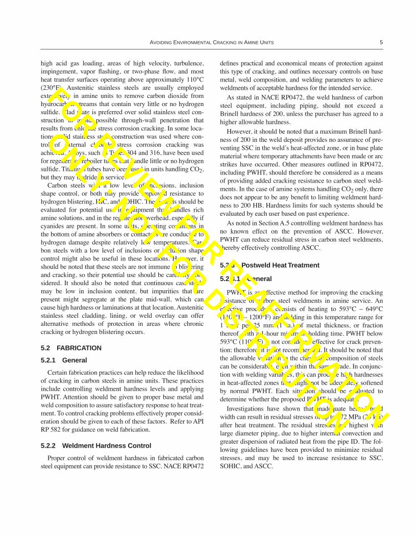
in a DEA unit. The elbow was made to ASTM A234 WPBspeciÞcations, and the piping class required stress relief afterwelding. The operating temperature of the component wasapproximately 66¡C (150¡F). Prior to cracking, the elbow hadbeen heated by a torch to approximately 1093¡C (2000¡F) torelieve pump strain due to piping misalignment. This heatingprocedure resulted in high residual tensile stresses in theelbow that subsequently cracked in service. To relieve resid-ual stresses caused by the heating procedure, a stress relievingoperation should be performed as outlined in 5.2.3.1. FiguresA-7 and A-8 illustrate the intergranular cracking that initiatedfrom the internal surface o f the elbow, and verify that aminecracking occurred in the line.
Note: The top panel illustrates alkaline stress corrosion cracks in apipe weld in an MEA unit; nital etched specimen at 6X magniÞca-tion. The bottom panel illustrates the intergranular nature of thecracks; nital etched at 200X magniÞcation
Figure A-6—Alkaline Stress Corrosion Cracking in a Pipe Weld in MEA Service
FOR REVIEW FOR REAFFIRMATION
ONLY; NOT FOR DISTRIBUTION
AVOIDING ENVIRONMENTAL CRACKING IN AMINE UNITS 17
Note: The top panel shows the location of circumferential cracks in apiping elbow from a DEA unit. The bottom panel conÞrms thecracks initiated on the ID surface.
Figure A-7—Alkaline Stress Corrosion Cracking in an Elbow in DEA Service
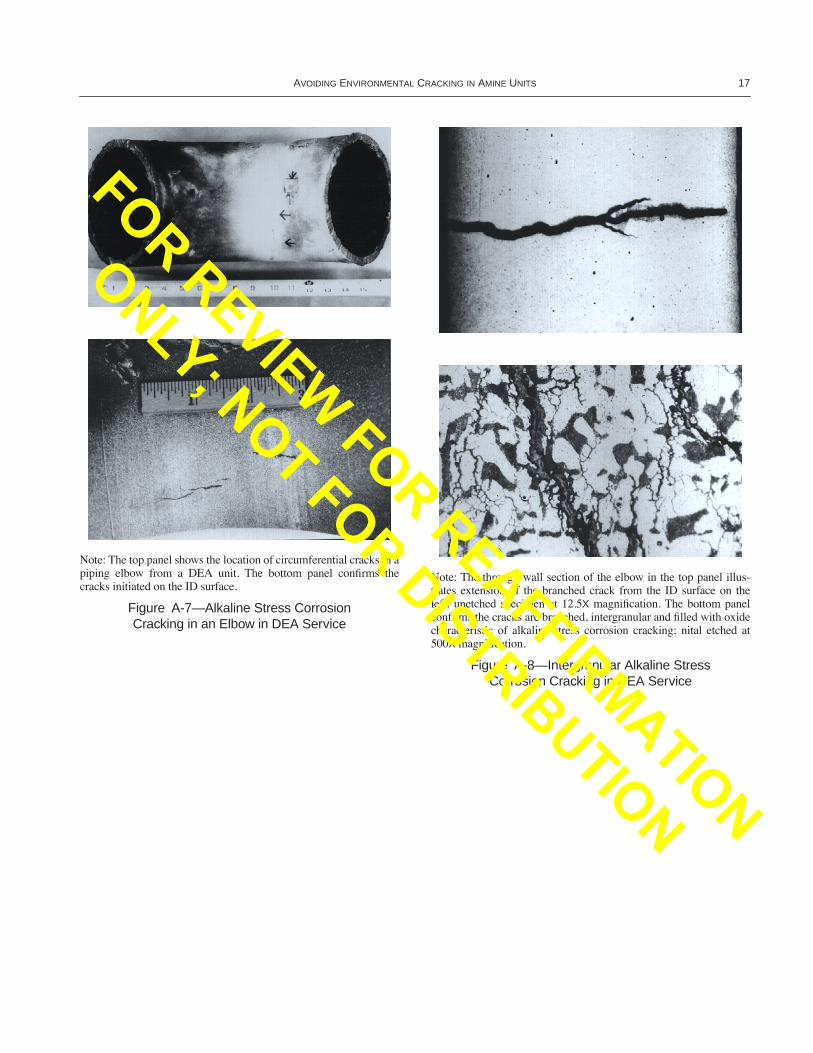
Note: The through-wall section of the elbow in the top panel illus-trates extension of the branched crack from the ID surface on theleft; unetched specimen at 12.5X magniÞcation. The bottom panelconÞrms the cracks are branched, intergranular and Þlled with oxidecharacteristic of alkaline stress corrosion cracking; nital etched at500X magniÞcation.
Figure A-8—Intergranular Alkaline Stress Corrosion Cracking in DEA Service
FOR REVIEW FOR REAFFIRMATION
ONLY; NOT FOR DISTRIBUTION

FOR REVIEW FOR REAFFIRMATION
ONLY; NOT FOR DISTRIBUTION

19
APPENDIX B—CONSIDERATIONS FOR CORROSION CONTROL
B.1 Scope
This appendix provides information based on industryexperience regarding corrosion control in amine units. Theinformation does not present, nor is it intended to establish,mandatory practices for the design and operation of amineunits. This information is intended to assist in the develop-ment of systems and procedures for individual companyneeds. Many companies safely operate amine units usingpractices different from those presented below. New or alter-native practices should not be discouraged, since they inevita-bly result in more effective amine unit technology for theindustry.
B.2 General
In low-pressure systems, corrosion of carbon steel can bemost severe in units that primarily remove carbon dioxide.Corrosion of carbon steel components has been least severe inunits that remove only hydrogen sulÞde, and in units that han-dle mixtures of carbon dioxide and hydrogen sulÞde. In high-pressure units with high hydrogen sulÞde partial pressure,corrosion of carbon steel can be severe. Corrosion in amineunits that use MEA can be more severe than in those that useDEA, because MEA is more prone to degradation. However,amine solutions such as DEA that are normally not puriÞedby reclaiming can also become quite corrosive.
MDEA has become a major alternative to DEA or MEAfor the removal of acid gases. There are process advantagesfor MDEA over conventional amines. These advantages areacid gas selectivity, energy savings, and the ability to operateat higher concentrations than MEA or DEA. A typical MDEAplant can operate at up to 50 percent concentration. MDEAunits have been used to remove H2S as well as H2S/CO2 andCO2. Some acid gas removal units have been speciÞcallydesigned to run on MDEA. These units may have specialdesign features unique to these plants, such as a desorber col-umn located upstream of the main stripper column. Otherunits have been converted from MEA or DEA with few, ifany, equipment changes. See B.7.3.5 for precautions.
From a practical point of view, corrosion control proce-dures in amine units concentrate on: the removal of certaincorrosive species from amine solutions by side-stream Þltra-tion, reclaiming, or both; the use of effective corrosion inhibi-tors; and the application of proven process schemes,equipment designs, and operating criteria, as outlined below.Corrosion (not necessarily cracking) has been most severe inunits that primarily remove carbon dioxide, that is, where thehydrogen sulÞde content of the acid gas is less than 5 percentby volume. Corrosion (not necessarily cracking) has beenleast severe in low-pressure units that remove only hydrogen
sulÞde, or that handle mixtures of the two gases containing atleast 5 percent by volume of hydrogen sulÞde.
B.3 Corrosion LocationsAttack is most pronounced at locations where acid gases
are desorbed (ßashed) from rich amine solution, and wheretemperatures and ßow turbulence are highest. Typical prob-lem areas include the regenerator tower reboiler, the lowersection of the regenerator tower, the rich amine side of thelean/rich amine exchangers, amine solution pumps, the pres-sure let-down valve and downstream piping, and thereclaimer (where used). The overhead system of the regenera-tor tower can be affected where acid gases tend to concen-trate. Severe hydrogen blistering can also be encountered inthe bottom of the absorber or contactor tower. Vessel shellareas that face the incoming inlet opening can becomeseverely corroded because the normally protective sulÞdeÞlm is removed by stream impingement.
Corrosion of carbon steel components can take the form ofuniform thinning, localized attack, or pitting, depending onlocation. Directionality in the pattern of attack can be attrib-uted to excessive ßow velocities and pressure drops. Corro-sion can also be severe on heat transfer surfaces. Depositsoften accelerate attack, especially on heat transfer surfaces.The localized overheating of reboiler and reclaimer tubesinside of bafße holes can cause groove-type corrosion. Prefer-ential weld corrosion of carbon steel can also occur in hot,rich amine solutions.
B.4 Filtration and ReclaimingPrecipitates such as iron sulÞde can be removed from
amine solutions by Þltration, using cartridge-type Þlters.High-molecular-weight degradation products can be elimi-nated by adsorption, using a bed of activated carbon. Typi-cally, 5 percent or more of the circulating amine solution ispassed through the Þlters. MEA solutions can be puriÞed byreclaiming, or by semicontinuous steam distillation with sodaash or caustic that has been added to liberate the amine fromthe acid salts. When reclaiming is used, it is usually per-formed on a 1 to 2 percent slipstream of the circulating aminesolution. DEA and MDEA solutions cannot be efÞcientlyreclaimed because of boiling-point constraints. DIPA solu-tions can be reclaimed.
B.5 Corrosion InhibitorsOver the years, a variety of corrosion inhibitors have been
evaluated in amine solutions in an attempt to reduce corrosionproblems. Corrosion inhibitors that have been and are beingused include high-molecular-weight Þlming amines, inor-ganic and organic oxidizing salts, and chemical oxygen scav-
FOR REVIEW FOR REAFFIRMATION
ONLY; NOT FOR DISTRIBUTION

20 API RECOMMENDED PRACTICE 945
engers. A number of proprietary multicomponent inhibitorpackages are also available. These chemicals are designed foramine units that handle acid gases with or without hydrogensulÞde. Certain oxidizing inhibitors react with hydrogen sul-Þde and should not be used in amine units that remove hydro-gen sulÞde. As a rule, corrosion inhibitors based on Þlmingamines have been relatively ineffective.
Some Þlming-amine inhibitors also contain sequesteringagents that aid in keeping the circulating amine solutionclean. Sequestering agents also solubilize the protective ironoxide Þlm that is normally present on steel exposed to leanamine solutions. This lowers the metal potential and can pro-mote ASCC [5]. Oxidizing salts will increase metal potentialand promote passivation of steel surfaces. If used in sufÞ-ciently high concentration, oxidizing salts may preventASCC.
B.6 Guidelines for Process and Equipment Design
B.6.1 GENERAL
To reduce energy costs and minimize sludge disposal prob-lems, many amine units are now designed to handle highersolution loadings. Higher solution loadings can result inincreased corrosion of carbon steel if proper precautions arenot taken. Industry experience has shown the non-mandatoryguidelines listed in B.6.2 to be useful in the design of suchunits. Other practices have been found to be equally suitable,based on experience in particular cases.
B.6.2 GUIDELINES
B.6.2.1 Minimize ßow velocities in heat exchangers andpiping in rich amine service. Velocities less than 1.8 m/sec (6ft/sec) may be used if no other operating experience is avail-able.
B.6.2.2 Place the rich solution on the tube side of lean/richamine exchangers.
B.6.2.3 Avoid ßashing of acid gases in lean/rich amineexchangers by locating the pressure let-down valve down-stream of the last exchanger. This prevents acid gas frombeing released into the exchangers.
B.6.2.4 Reduce erosion-corrosion at inlet nozzles by usingimpingement plates or dummy rods.
B.6.2.5 Specify as low a pressure as is possible for theregenerator tower and associated reboilers.
B.6.2.6 Use low-pressure steam [345 kPa (50 psig) or less]as the reboiler heating medium, and maintain low reboilertemperatures to minimize amine decomposition [a limit of149¡C (300¡F) may be used if no other data are available].
B.6.2.7 Use a square-pitch tube layout (or remove interiortubes) to reduce vapor blanketing in reboiler bundles.
B.6.2.8 Locate the steam ßow valve ahead of the reboilerto prevent condensate from ßooding the tubes.
B.6.2.9 Use oversized pressure let-down valves to reduceerosion-corrosion caused by velocity effects. Let-down valvesfor high-pressure units should have hard-faced internals. Let-down valves in high-concentration carbon dioxide systemsshould be stainless steel.
B.6.2.10 Specify long-radius elbows and adequately sizedprocess piping to minimize erosion-corrosion in transfer linesas a result of excessive ßow turbulence. Stainless steel hasbeen successfully used for two-phase ßow piping in high con-centration carbon dioxide systems.
B.6.2.11 Provide an amine reclaimer for MEA units.
B.6.2.12 Design the regenerator reboiler and aminereclaimer to assure that their tube bundles are fully immersedin process liquid at all times.
B.6.2.13 Provide inert-gas blanketing for storage and surgevessels to reduce oxygen degradation of amine solutions.
B.6.2.14 If a Þlter is used, size it for not less than 5 percentof the amine circulation and less than 0.1 weight percent sol-ids content.
B.7 Guidelines for Operation
B.7.1 GENERAL
Effective operating procedures should prevent buildup ofpotentially harmful degradation products and should keep theamine solution clean. Properly maintained solutions willreduce corrosion and may obviate the need for corrosioninhibitors. Industry experience has shown that the non-man-datory guidelines given in B.7.2 and B.7.3 are useful for pre-venting serious corrosion. However, as noted in B.6.1, otherpractices may be equally suitable, based on experience withspeciÞc units.
B.7.2 OVERALL GUIDELINES
B.7.2.1 Closely monitor corrosion inhibitors that are beingÞeld tested for the intended application.
B.7.2.2 If an amine reclaimer is incorporated in the unit,keep it in proper operating condition.
B.7.2.3 Use concentrations and grades of caustic soda orsoda ash that are compatible with the reclaimerÕs constructionmaterials. The use of low-chloride caustic is advisable withreclaimers that have austenitic stainless steel tubes.
B.7.2.4 Use only oxygen-free steam condensate to prepareamine solutions.
FOR REVIEW FOR REAFFIRMATION
ONLY; NOT FOR DISTRIBUTION

AVOIDING ENVIRONMENTAL CRACKING IN AMINE UNITS 21
B.7.2.5 Analyze amine solutions periodically to monitorthe concentration of heat-stable salts, carboxylic acids, andheat-stable compounds of carbon dioxide with alkanolamine(oxazolidones).
B.7.3 GUIDELINES FOR SPECIFIC OPERATING UNITS
B.7.3.1 General
Depending on the type of amine solution that will be used,speciÞc operating guidelines, such as those given in B.7.3.2and B.7.3.3, might apply.
B.7.3.2 MEA Units
For MEA units, reboiler temperatures maintained below149¡C (300¡F) will help to minimize amine degradation andthe corrosion of reboiler tubes. MEA concentrations above 25percent by volume, and acid gas loading above 0.35 mole permole of amine, should be carefully evaluated in regard to therequirements for construction materials. The use of corrosion-resistant alloys may permit higher temperatures, amine con-centrations, and gas loadings. Mitigate overhead piping andequipment corrosion by operating the regenerator so that 0.5percent amine is passed overhead. The presence of the amineprevents acidic corrosion in carbon-steel overhead systems.Alternatively, a corrosion-resistant alloy may prove useful.
B.7.3.3 DEA Units
The speciÞc guidelines for DEA units are similar to thosefor MEA units, except that DEA concentrations and acid gasloadings may be higher. Recent experience has demonstratedsuccessful operation of DEA units at concentrations of 40percent by volume, and acid gas loadings of up to 0.5 moleper mole of amine. Corrosion monitoring is advisable whenoperating with higher amine concentrations and gas loadings.
B.7.3.4 DIPA Units
Rich solutions of DIPA and DIPA with sulfolane generallydo not corrode carbon steel because protective Þlms arereadily formed. Corrosion might occur where process condi-tions lead to ßashing and/or boiling. Apparently, carbon diox-ide ßashing has been responsible for some contactorcorrosion. A critical variable seems to be the carbon dioxide-to-hydrogen sulÞde ratio, which was less than 1-to-8 whencorrosion occurred. In carbon-dioxide rich DIPA systems, thecorrosion of carbon steel is controlled by the metal wall tem-peratures and the degree of vaporization at the wall surface. Ifprocess conditions prevent temperature and vaporization con-trol, Type 304 stainless steel will provide satisfactory resis-tance in place of the carbon steel.
B.7.3.5 MDEA Units
One of the original claims made about MDEA was thatunlike MEA or DEA, it was not corrosive to carbon steel.Claims were also made that degradation would not be a prob-lem because MDEA resisted degradation by CS2 and COS.However, actual plant experience has shown mixed results. InH2S and H2S-rich units, corrosion of carbon steel has beenlow due to the protective iron sulÞde scale. However, severecorrosion has been experienced in CO2 or CO2-rich units.Furthermore, while MDEA seems to resist CS2 or COSinduced degradation, it is highly sensitive to oxygen and ther-mal degradation.
Similar to DEA, the degradation products of MDEA can-not be reclaimed. For this reason, it is very important to pre-vent the formation of the degradation products by exclusionof oxygen from the system. MDEA systems with high levelsof degradation products in circulation exhibit signiÞcant cor-rosion. To remove the degradation and suspended products,Þltration should be used. For most units, both mechanical Þl-tration and activated carbon Þlters are recommended. As inother amine units, high velocity and turbulence can causelocalized erosion-corrosion. In MDEA units it is advisable tokeep the velocity to under 1.8 m/sec (6 ft/sec). Oxidative-typeinhibitors, common in CO2 removal units, should not be usedin MDEA units, especially for those converted from MEA.
Claims that MDEA units can be completely built with car-bon steel equipment have not been validated in the Þeld.Selective upgrading of materials for MDEA should be similarto other amine units. CO2 removal units require the mostupgrades. Typical equipment items that might requireupgrades are: the stripper tower, desorber tower (if oneexists), lean/rich exchanger, and the stripper reboiler. Whenupgrading is required for towers or exchanger shells, they arenormally lined with 300 series stainless steel. Low-carbonand stabilized grades of stainless steels (Types 304L, 316L,and 321) are preferred. Similarly, low-carbon or stabilizedgrades of tubes should be used for U-tube bundles to preventsensitization during stress relief of bends.
B.7.3.6 DGA Units
Diglycolamine (DGA) systems are less corrosive thanMEA systems. DGA corrosion characteristics are similar toother amine systems and depend on temperature, ßuid veloc-ity, concentration, and loading. Fluid velocity for carbon steelpiping should not exceed 1.5 m/sec (5 ft/sec). In 40 percentDGA that treats CO2 and H2S acid gases, at least 5 percentH2S in the CO2/H2S mix is required to avoid corrosion in thereclaimers. Type 304 stainless steel is resistant to highervelocities, temperatures, and CO2 concentrations than carbonsteel; however, the chloride level must be kept below 4000ppm to prevent pitting of the stainless steel.
FOR REVIEW FOR REAFFIRMATION
ONLY; NOT FOR DISTRIBUTION

FOR REVIEW FOR REAFFIRMATION
ONLY; NOT FOR DISTRIBUTION

23
APPENDIX C—REQUEST FOR NEW INFORMATION CONCERNING PROBLEMS WITH ENVIRONMENTAL CRACKING IN AMINE UNITS
The information contained in this recommended practice isbased on experience and engineering practices current at thetime of its preparation. It is recognized that in the future,additional information will become available about problemsthat affect amine units and improved procedures to overcomethem. Such information is of particular interest to the APISubcommittee on Corrosion and Materials, which is respon-sible for the preparation and periodic revision of this recom-mended practice.
The following pages contain a report form that lists thebasic information that should be provided when details ofenvironmental cracking problems with amine units are for-warded. Additional information may be included in attach-ments to these data sheets. Please provide as many details aspossible. General photographs of the equipment affected are
of value. Photomicrographs of the construction materialÕsmicrostructure are also of signiÞcant interest, particularlythose that delineate the nature and location of any crackspresent. Actual metal samples may also be forwarded.
The completed form or a legible facsimile should be sent tothe following address:
Chairman, Recommended Practice 945 Task GroupAPI Subcommittee on Corrosion and Materialsc/o Standards DepartmentAmerican Petroleum Institute1220 L Street, N.W.Washington, D.C. 20005 [email protected]
FOR REVIEW FOR REAFFIRMATION
ONLY; NOT FOR DISTRIBUTION

24 API RECOMMENDED PRACTICE 945
API REPORT FORM:ENVIRONMENTALCRACKING PROBLEMS INANIME UNITS
Date ___________________API File No. ___________________Page ________ of ________
Name ________________________________________________________
Company affiliation __________________________________________________
Address ________________________________________________________________________________________________________________________________________________________________________
Country ________________________________________________________
Telephone
E-mail ________________________
1. Type of anime unit (e.g., MEA, DEA)________________________________________________________
2. Location (e.g., refinery, chemical plant)________________________________________________________
3. Acid gas being scrubbed (e.g., H2S, CO2)________________________________________________________
4. Anime concentration (%)________________________________________________________
5. Solution loading (moles of acid gas per mole of amine)________________________________________________________
6. Corrosion inhibitor, if used________________________________________________________
7. Date of unit construction________________________________________________________
8. Date of problem________________________________________________________
9. Equipment affected (e.g., vessel, exchanger, piping)________________________________________________________
10. Location of problem (e.g., vessel shell, pipe weld)________________________________________________________
11. Metal temperature at location: normal, maximum________________________________________________________
FAX
FOR REVIEW FOR REAFFIRMATION
ONLY; NOT FOR DISTRIBUTION

AVOIDING ENVIRONMENTAL CRACKING IN AMINE UNITS 25
API REPORT FORM:ENVIRONMENTALCRACKING PROBLEMS INAMINE UNITS
Date ___________________API File No. ___________________Page ________ of ________
12. Construction material (ASTM designation or equivalent)________________________________________________________
13. Material strength level________________________________________________________
14. Wall thickness, pipe diameter, and schedule________________________________________________________
15. Postweld heat treatment (PWHT) ___ Yes ___ No
16. PWHT time ______________ PWHT temperature _____________
17. Material hardness at location________________________________________________________
18. Equipment steam-out cleaned? ___ Yes ___ No
19. Equipment water washed? ___ Yes ___ No
20. Description of problem (include photographs and samples,if available):________________________________________________________________________________________________________________________________________________________________________________________________________________________________________________________________________________________________________________________________________________________________________________________________________
21. Have other amines been used in equipment in the past?___ Yes ___ NoIf yes, provide information about the type of amine, and theconditions under which it was used:________________________________________________________________________________________________________________________________________________________________________________________________________________________________________________________________________________________________________________________________________________________________________________________________________
FOR REVIEW FOR REAFFIRMATION
ONLY; NOT FOR DISTRIBUTION

FOR REVIEW FOR REAFFIRMATION
ONLY; NOT FOR DISTRIBUTION

06/03
FOR REVIEW FOR REAFFIRMATION
ONLY; NOT FOR DISTRIBUTION

Additional copies are available through Global EngineeringDocuments at (800) 854-7179 or (303) 397-7956
Information about API Publications, Programs and Services isavailable on the World Wide Web at: http://www.api.org
Product No. C94503
FOR REVIEW FOR REAFFIRMATION
ONLY; NOT FOR DISTRIBUTION