for basic settings the following menu is started by
TRANSCRIPT

- 1 -
Professional 4G Cellular Weather Station
Operation Manual
Model: WS6006
Note: The stainless steel pole is not included

- 2 -
Contents
1 Introduction........................................................................................................4
2 Unpacking..........................................................................................................5
3 OVERVIEW...................................................................................................... 7
3.1 Outdoor 7-in-1 sensor array:.......................................................................7
3.2 Indoor sensor:............................................................................................. 8
3.3 PM 2.5 Sensor (Sold separately):............................................................... 8
3.4 Soil Moisture Sensor(Sold separately):...................................................... 8
3.5 Receiver unit...............................................................................................9
3.6 Solar panel Unit........................................................................................ 10
3.7 Features.....................................................................................................10
4 Installation....................................................................................................... 12
4.1 Outdoor unit..............................................................................................12
4.1.1 Install U-bolts and metal plate...........................................................12
4.1.2 Install wind vane................................................................................13
4.1.3 Install wind speed cups......................................................................14
4.1.4 Install batteries in sensor package..................................................... 14
4.1.5 Mount assembled outdoor sensor package........................................ 15
4.1.5.1 Before you mount........................................................... 15
4.1.5.2 Mounting.........................................................................15
4.1.6 Reset Button and Transmitter LED................................................... 17
4.2 Indoor Sensor Set Up................................................................................18
4.2.1 Sensor Placement...............................................................................18
4.3 Best Practices for Wireless Communication........................................... 20
4.4 Initial Receiver Unit Set Up..................................................................... 21
5 USB Configure Tool Operation.......................................................................26

- 3 -
5.1 Setup Menu...............................................................................................27
5.2 Basic Settings............................................................................................27
5.3 Alarm........................................................................................................ 28
5.4 Calibration................................................................................................ 28
5.5 Rain...........................................................................................................31
5.6 Mobile Network........................................................................................32
5.7 Record Menu.............................................................................................33
5.8 SDCard File.............................................................................................. 34
5.9 Upload.......................................................................................................35
5.10 Update Firmware.................................................................................... 37
5.11 Factory Reset.......................................................................................... 38
6 Mobile Phone Control via SMS.......................................................................39
6.1 SMS data from station.............................................................................. 42
6.2 Low Power alarm......................................................................................43
7 Weather Server................................................................................................ 44
7.1 Viewing data on ecowitt.net..................................................................... 45
7.2 Registering with and using wunderground.com....................................... 48
7.3 Viewing data on wunderground.com........................................................50
7.4 Registering with and using Weathercloud...............................................54
7.5 Registering with Weather Observations Website (WOW).......................55
8 Maintenance.....................................................................................................59
9 Troubleshooting Guide.................................................................................... 61
10 Specifications.................................................................................................63
11 Warranty Information.................................................................................... 64

- 4 -
1 Introduction
Thank you for purchasing this professional weather station. This deviceis working based on 4G WCDMA /GSM network. It can be configuredto send data to a specified server by WCDMA/GSM so that users canrun remote monitoring of weather condition.
This manual will guide you step-by-step through setting up your device.Use this manual to become familiar with your professional weatherstation, and save it for future reference.
The device can measure the below weather data and transmit them tothe public weather server: www.wunderground.com by 4GWCDMA/GSM network.
1. Wind direction 8. Indoor Temperature
2. Wind speed 9.Indoor Humidity
3.Solar radiation rate 10.Outdoor Temperature
4.UV index 11.Outdoor Humidity
5.Absolute pressure 12.Dew point
6.Relative pressure 13.Rain fall
7.Gust 14.PM 2.5 concentration(Sensor sold separately)
15.Soil moisture(Sensor sold separately)

- 5 -
2 Unpacking
Open your weather station box and inspect that the contents are intact(nothing broken) and complete (nothing missing). Inside you shouldfind the following:
QTY Item Description1 Receiver unit1 Outdoor Sensor Body with built-in: Thermo-hygrometer / Rain Gauge
/ Wind Speed Sensor/ Wind Direction Sensor, Light and UV sensor,Solar panel
1 Wind speed cups (to be attached to outdoor sensor body)1 Wind vane (to be attached to outdoor sensor body)2 U-Bolts for mounting on a pole4 Threaded nuts for U-Bolts (M5 size)1 Metal mounting plate to be used with U-Bolts1 Wrench for M5 bolts1 Solar panel1 Metal mounting plate to be used with solar panel1 Mounting hose clamp to be used with solar panel1 Indoor temperature & humidity sensor1 USB cable1 5 meter connection cable for solar panel to connect to Receiver1 18650 li-ion battery for receiver unit1 User manual
If components are missing from the package, or broken, please contactcustomer service to resolve the issue.
Note: The receiver unit can store historical data on a memory card. Thismemory card is not included. If you want to use one you will need a TFmemory card.
Note: Batteries for the outdoor sensor package are not included. Youwill need 2 AA size batteries, alkaline or Lithium batteries (Lithiumrecommended for colder climates).
Note: The receiver unit is powered by a 18650 li-ion battery or USBcharger. And also with a solar panel as backup power supply. Allincluded.

- 6 -
Note: When select the SIM card, please check the following supportedfrequency band first (you may confirm that with your mobile network serviceprovider):
North America:
LTE-FDD: B2/B4/B5/B12/B13/B17/B25/B26
LTE-TDD:B41
WCDMA:B2/B4/B5
CDMA&EVDO:BC0/BC1
GSM:850/900/1800/1900
Europe:
LTE-FDD: B1/B3/B5/B7/B8/B20
LTE-TDD:B40
WCDMA:B1/B5/B8
GSM:850/900/1800/1900
Australia:
LTE-FDD:B1/B3/B5/B7/B8/B28
LTE-TDD:B40
WCDMA:B1/B5/B8
GSM:850/900/1800/1900
South America:
LTE-FDD: B3/B4/B5/B7/B8/B28
LTE-TDD:B40
WCDMA:B2/B5/B8
GSM:850/900/1800/1900

- 7 -
3 OVERVIEW
3.1 Outdoor 7-in-1 sensor array:
1. Wind Speed cups 7. Antenna2. Wind Vane 8. U-Bolts3. Thermo- and hygro-meter sensors 9. Battery compartment door4. Rain collector 10. Reset button5. Bubble level 11. LED (red) to indicate data
transmission6. Solar panel 12.Light sensor and UV sensor

- 8 -
3.2 Indoor sensor:
3.3 PM 2.5 Sensor (Sold separately):
3.4 Soil Moisture Sensor(Sold separately):

- 9 -
3.5 Receiver unit
Outside
Inside
1. +/- electrode symbol of battery
2. TF card slot
3. USB interface
4. Reset button
5. Micro SIM card slot
6. Nano SIM card slot
7. Connector for solar power unit

- 10 -
3.6 Solar panel Unit
The solar panel base is to be connected to the power connector forreceiver via a 2 core 5 meter extending cable.
3.7 Features
Receive the following weather data from outdoor integrated sensor:
Indoor/Outdoor temperature and humidity
Wind speed, gust speed, and wind direction
Absolute and Relative barometric pressure
Rainfall rate and totals for day, week, month, year and life-time total
Calculated wind chill, dew point and heat index
Solar light intensity and UV index
Selectable display units for each sensor: C or F (temperature); mph,km/h, m/s, knots or Beaufort (wind speed); inHg, hPa or mmHg(pressure); in or mm (rainfall); lux, fc or w/m2 (solar lighting)
Maximum and minimum values for sensors
High/low alarm options for sensors

- 11 -
Can be configured with WH41 PM 2.5 air quality sensor and WH51soil moisture sensor (all sold separately)
Data preserved during battery change
PC software (USB connection)
Send alarm message to mobile by SMS
The data saved as CSV file on the SD card
Transmission span time is programmable by user from 0 or 10minute to24hour (0 is not send the data via WCDMA network)
Pushes sensor data to cloud weather services: https://www.ecowitt.net https://www.wunderground.com https://www.weathercloud.com/ https://www.wow.com Custom sites using Wunderground protocol. Data storage service on Ecowitt server: https://ecowitt.net Stores data for past six months at 5-minute intervals Stores data for past year at 30-minute intervals
Note: If you purchased the optional WH51/WH41 sensors, please go to ourwebsite to download the instruction manual:https://www.ecowitt.com/shop/manualDownload

- 12 -
4 Installation
Before placing and installing all components of the weather station attheir final destination, please set up the weather station with all partsbeing nearby for testing the correct function. Also please noteconfiguring parameters on PC software is necessary before permanentinstallation. (Refer to USB Configure Tool Operation part).
To complete assembly you will need a Philips screwdriver (size PH2) ,a Slotted screwdriver (size SL2) and a wrench (size M5; included inpackage).
4.1 Outdoor unit
4.1.1 Install U-bolts and metal plate
Installation of the U-bolts, which are in turn used to mount the sensorpackage on a pole, requires installation of an included metal plate toreceive the U-bolt ends. The metal plate, visible in Figure 1 on the rightside, has four holes through which the ends of the two U-Bolts will fit.The plate itself is inserted in a groove on the bottom of the unit(opposite side of solar panel). Note that one side of the plate has astraight edge (which goes into the groove), the other side is bent at a 90-degree angle and has a curved profile (which will end up “hugging” themounting pole). Once the metal plate is inserted, remove nuts from theU-Bolts and insert both U-bolts through the respective holes of themetal plate as shown in Figure 1.
Figure1: U-Bolt installation

- 13 -
Loosely screw on the nuts on the ends of the U-bolts. You will tightenthese later during final mounting. Final assembly is shown in Figure 2.
Figure 2: U-Bolts and nuts installed
The plate and U-Bolts are not yet needed at this stage but doing thisnow may help avoid damaging wind vane and wind speed cups later on.Handling of the sensor package with wind vane and speed cups installedto install these bolts is more difficult and more likely to lead to damage.
4.1.2 Install wind vane
Push the wind vane onto the shaft on the bottom side of the sensorpackage, until it goes no further, as shown on the left side in Figure 3.Next, tighten the set screw, with a Philips screwdriver (size PH2), asshown on the right side, until the wind vane cannot be removed fromthe axle. Make sure the wind vane can rotate freely. The wind vane’smovement has a small amount of friction, which is helpful in providingsteady wind direction measurements.
Figure 3: Wind vane installation diagram

- 14 -
4.1.3 Install wind speed cups
Push the wind speed cup assembly onto the shaft on the opposite side ofthe wind vane, as shown in Figure 4 on the left side. Tighten the setscrew, with a Philips screwdriver (size PH2), as shown on the right side.Make sure the cup assembly can rotate freely. There should be nonoticeable friction when it is turning.
Figure 4: Wind speed cup installation diagram
4.1.4 Install batteries in sensor package
Open the battery compartment with a screwdriver and insert 2 AAbatteries in the battery compartment. The LED indicator on the back ofthe sensor package (item 9) will turn on for four seconds and then flashonce every 16 seconds indicating sensor data transmission. If you didnot pay attention, you may have missed the initial indication. You canalways remove the batteries and start over, but if you see the flash onceevery 16 seconds, everything should be OK.
Figure 5: Battery installation diagram
Note: If no LED light up or is lighted permanently, make sure thebattery is inserted the correct way or a proper reset is happened. Do not

- 15 -
install the batteries backwards. You can permanently damage theoutdoor sensor.
Note: We recommend lithium batteries for cold weather climates, butalkaline batteries are sufficient for most climates. We do notrecommend rechargeable batteries. They have lower voltages, do notoperate well at wide temperature ranges, and do not last as long,resulting in poorer reception.
4.1.5Mount assembled outdoor sensor package
4.1.5.1 Before you mount
Before proceeding with the outdoor mounting detailed in this section,you may want to skip to setup instructions in section Indoor Sensor SetUp (Section 4.2) and onwards first, while you keep the assembledoutdoor sensor package nearby (although preferably not closer than 5 ft.from the receiver unit). This will make any troubleshooting andadjustments easier and avoids any distance or interference related issuesfrom the setup.
After setup is complete and everything is working, return here foroutdoor mounting. If issues show up after outdoor mounting they arealmost certainly related to distance, obstacles etc.
4.1.5.2Mounting
You can attach a pipe to a permanent structure and then attach thesensor package to it (see Figure 6). The U-Bolts will accommodate apipe diameter of 1-2 inches (pipe not included).

- 16 -
Figure 6: Sensor package mounting diagram
Make sure the mounting pipe is vertical, or very close to it. Use a levelif needed.
Finally, place the sensor package on top of the prepared mounting pipe.The U-Bolts should be loose enough to allow this but loosen the nuts asnecessary. Once placed, hand tightens all four nuts, taking care to do soevenly. Do not use a wrench yet!
Now you will need to align the whole package in the proper direction byrotating it on top of the mounting pipe as needed. Locate the arrowlabeled “WEST” that you will find on top of the sensor package rightnext to the light sensor, on the opposite side of the solar panel. Youmust rotate the whole sensor package until this arrow points due west.To achieve proper alignment, it is helpful to use a compass (many cellphones have a compass application). Once rotated in the correctorientation, lightly tighten the bolts a little more (use a wrench) toprevent further rotation.
Note: The orientation to WEST is necessary for two reasons. The mostimportant one is to position the solar panel and light sensor in the mostadvantageous position for recording solar radiation and charginginternal capacitors. Secondly it causes a zero reading for wind directionto correspond to due NORTH, as is customary. This orientation iscorrect for installations in the northern hemisphere. If you are installingin the southern hemisphere, the correct orientation to achieve the sameoptimal positioning is to have the “WEST” arrow actually point due

- 17 -
EAST! This has the side effect, however, of lining up the 0 reading ofthe wind direction with SOUTH. This needs to be corrected using a180-degree offset in the calibration settings (see section Calibration).
Now look at the bubble level. The bubble should be fully inside the redcircle. If it is not, wind direction, speed, and rain readings may notoperate correctly or accurately. Adjust the mounting pipe as necessary.If the bubble is close, but not quite inside the circle, and you cannotadjust the mounting pipe, you may have to experiment with smallwooden or heavy cardboard shims between the sensor package and thetop of the mounting pole to achieve the desired result (this will requireloosening the bolts and some experimentation).
Make sure you check, and correct if necessary, the westerly orientationas the final installation step, and now tighten the bolts with a wrench.Do not over tighten, but make sure strong wind and/or rain cannot movethe sensor package.
Note: If you tested the full assembly indoors and then came back herefor instructions and mounted to sensor package outdoor you may wantto make some further adjustments on the receiver unit. Thetransportation from indoor to outdoor and handling of the sensor islikely to have “tripped” the rainfall sensing bucket one or more timesand consequently the receiver unit may have registered rainfall that didnot really exist. You can use pc software to clear this from history.Doing so is also important to avoid false registration of these readingswith weather services.
4.1.6 Reset Button and Transmitter LED
In the event the sensor array is not transmitting, reset the sensor array.
Using a bent-open paperclip, press and hold the RESET BUTTON (seeFigure 7) to affect a reset: the LED turns on while the RESET button isdepressed, and you can now let go. The LED should then resume asnormal, flashing approximately once every 16 seconds.

- 18 -
Figure 7: Reset button and Transmitter LED location
4.2 Indoor Sensor Set Up
Note: To avoid permanent damage, please take note of the batterypolarity before inserting the batteries. Looking at Figure 8 from left toright the left-most (or bottom) battery is to be installed with its +terminal pointing down, and the other battery with its + terminalpointing up.
Remove the battery door on the back of the sensor by sliding it in thedirection of the arrow. Insert two AA batteries as described and putcompartment door back and slide it in the opposite direction to lock.
Figure 8: Indoor sensor battery installation
4.2.1 Sensor Placement
The best mounting location for the indoor sensor is in a location thatnever receives direct sunlight, not even through windows. Also, do notinstall in a location where a nearby radiant heat source (radiator, heaters,

- 19 -
etc.) will affect it. Direct sunlight and radiant heat sources will result ininaccurate temperature readings.
The sensor is meant to provide indoor conditions for display on theconsole, but if you would rather have a second source for outdoorconditions instead, you can mount this unit outside. The unit isweatherproof, but besides heeding the placement instructions above,you should also attempt to mount the unit under cover (eve or awning orsimilar).
To mount or hang the unit on a wall or wood beam:
Use a screw or nail to affix the remote sensor to the wall, as shown onthe left side of Figure 9, or
Hang the remote sensor using a string, as shown in right side of Figure 9
Figure 9: Indoor sensor mounting
Note:Make sure the sensor is mounted vertically and not lying down ona flat surface. This will insure optimum reception. Wireless signals areimpacted by distance, interference (other weather stations, wirelessphones, wireless routers, TVs and computer monitors), and transmissionbarriers, such as walls. In general, wireless signals will not penetratesolid metal and earth (down a hill, for example).

- 20 -
4.3 Best Practices for Wireless Communication
Wireless (RF) communication is susceptible to interference, distance,walls and metal barriers. We recommend the following best practicesfor trouble free wireless communication between both sensor packagesand the console:
Indoor sensor placement: The sensor will have the longest reachfor its signal when mounted or hung vertically. Avoid laying itdown on a flat surface.
Electro-Magnetic Interference (EMI). Keep the console severalfeet away from computer monitors and TVs.
Radio Frequency Interference (RFI). If you have other devicesoperating on the same frequency band as your indoor and/oroutdoor sensors and experience intermittent communicationbetween sensor package and console, try turning off these otherdevices for troubleshooting purposes. You may need to relocate thetransmitters or receivers to avoid the interference and establishreliable communication. The frequencies used by the sensors areone of (depending on your location): 433, 868, or 915 MHz (915MHz for United States).
Line of Sight Rating. This device is rated at 300 feet line of sight(under ideal circumstances; no interference, barriers or walls), butin most real-world scenarios, including a wall or two, you will beable to go about 100 feet.
Metal Barriers. Radio frequency will not pass through metalbarriers such as aluminum siding or metal wall framing. If you havesuch metal barriers and experience communication problems, youmust change the placement of sensor package and or console.
The following table shows different transmission media andexpected signal strength reductions. Each “wall” or obstructiondecreases the transmission range by the factor shown below.

- 21 -
Medium RF Signal Strength Reduction
Glass (untreated) 5-15%
Plastics 10-15%
Wood 10-40%
Brick 10-40%
Concrete 40-80%
Metal 90-100%
Table 1: RF Signal Strength reduction
4.4 Initial Receiver Unit Set Up
1. Before power on the device, please open the case (Figure 10) and usea 3G SIM card to install in one of the SIM card slots. (Figure 11).TheBigger slot is for micro SIM card and the other is for Nano SIM card.
Figure 10
Micro SIM card slot:
1.Unfold the foil of Micro sim card slot
2.Put the SIM card into the compartment.
3. Cover the foil and lock the slot.

- 22 -
Nano SIM card slot: Insert the sim card into slot directly asshown in Figure 11.
Figure 11
Note: The SIM card must support SMS and mobile data. SIM card lockmust be disabled. Prepaid SIM cards are not recommended, as data willnot be uploaded when you run out of credit.
Note: Please install only 1 SIM card to work.
2. Open the rubber seal on Micro SD card slot and install a Micro SDcard. (Figure 12)
Figure 12
3. Install the supplied li-ion battery into the battery chamber. Do notinstall the batteries incorrect to the polarity markings. You canpermanently damage the receiver.
The battery must be full charged before you set up the receiver unit. Tocharge the battery, Open the rubber seal on USB interface and connectthe receiver to PC or an USB charger via USB cable. Charge the battery

- 23 -
for 10 hours when first use take place, this is to assure battery is fullycharged.
4. Re-assemble the receiver and fix it on wall or vertical surfacewith flat wooden board. Please keep the side with micro SD cardslot and USB interface downward to make sure waterproof. Iffix on wall directly, please use an electrical drill to bore sizeableholes and insert the plastic inserts before you mount screws.
Mount the solar panel unit.
Please mount it near the receiver forextending cable between solar unit and receiver is only 5 meters. There are ametal holder,3 screws and 1 steel mounting loop included for solar panelmount.
Mounting Steps:a) Use a screw driver to assemble the metal holder on back of solar panel asshown in Figure 13.b) There are 2 slots on the metal holder for steel loop. Attach the loop to themetal holder as shown in Figure 14.c) Fix the loop on a mounting post and as shown in Figure 15. Make suresolar panel unit face sunlight.d) Connecting the solar panel to receiver unit. A 5 meter extending cable isfor option to extend the distance.

- 24 -
Figure 13
Figure 14
Figure 15

- 25 -
5. All LED lights will be light up after power on:
WCDMA/GSM network indicator: Once the device is establishing theconnection to internet, it will turn on and flash .The flash indicating data isuploading to website in a certain interval.(Set up on PC software).
Receiver switches between WCDMA and GSM automatically based onnetwork availability.
Quick flash in every 2 seconds means failure deliver. Please check thenetwork availability or the battery.
RF Data collecting indicator: It will flash when receive data fromoutdoor sensor or indoor sensor.
Quick flash in every 2 seconds means failure communication betweenindoor/outdoor sensor and receiver unit. Please check weather stationand re-establish the RF communication.
Power indicator: It flashes every 3 seconds during working.
Stop flashing means power failure. Please check battery.
6. Time and date will be synchronized with internet after start up.
7. Open the rubber seal on there is a RESET button beside the USBinterface. Use a clipper pin to push and trigger a complete reset.

- 26 -
5 USB Configure Tool Operation
Before using the weather station, you need to configure the settings on the PCvia”WEATHER LOGGER” pc software.
1. Download the latest pc software on this link:http://download.ecowitt.net/down/softwave?n=WeatherLogger
2. Decompress the Weather Logger file, open the Weather Logger Setup.exeto install the software.
3. Connect the receiver device to PC via an USB cable, and launch thesoftware.
When base unit is connected to PC, it shows “USB Connected” at the bottom ofscreen. If no base station is connected, it shows "USB Unconnected".
The main software UI is as follow:

- 27 -
5.1 Setup Menu
Click Setup menu, there are Basic settings, Alarm, Calibration, Rain, MobileNetwork options.
5.2 Basic Settings
Click Basic Settings option to enter setting menu. Units of weatherparameters, time zone, DST on/off, data logging interval can be configuredhere. Once you made your choice, press Save to make the setting effective.
Note: Whenever any one of the settings changed, a new log file will becreated on SD card (in case a card has mounted on machine) and havinghistory data recorded with the newly selected units effected.

- 28 -
5.3 Alarm
Alarm function is referring to sending alert SMS message to your mobile phonewhen alarm condition is triggered.
Click Alarm option to enter setting menu. The check box is to enablethe corresponded alarm condition.
5.4 Calibration
Click Calibration option to enter setting menu.
If the data measured by device is found not in complete accord with officialdata, a reference coefficient can be configured here to make it as accurate aspossible.

- 29 -
Parameter Type ofCalibration
Default Typical Calibration Source
REL
Barometer
Offset Current Value Local airport (3)
ABS
Barometer
Offset Current Value Calibrated laboratory gradebarometer
WindDirection
Offset Current Value GPS, Compass (4)
Temperature Offset Current Value Red Spirit or MercuryThermometer (1)
Humidity Offset Current Value Sling Psychrometer (2)
Wind Gain 1.00 Calibrated laboratory gradewind meter (6)
Rain Gain 1.00 Sight glass rain gauge with anaperture of at least 4” (7)
SolarRadiation
Gain 1.00 Calibrated laboratory gradesolar radiation sensor
(1) The receiver displays two different pressures: absolute(measured) and relative (corrected to sea-level).
To compare pressure conditions from one location to another,meteorologists correct pressure to sea-level conditions. Because the airpressure decreases as you rise in altitude, the sea-level correctedpressure (the pressure your location would be at if located at sea-level)is generally higher than your measured pressure.
Thus, your absolute pressure may read 28.62 inHg (969 mb) at analtitude of 1000 feet (305 m), but the relative pressure is 30.00 inHg(1016 mb).
The standard sea-level pressure is 29.92 in Hg (1013 mb). This is the

- 30 -
average sea-level pressure around the world. Relative pressuremeasurements greater than 29.92 inHg (1013 mb) are considered highpressure and relative pressure measurements less than 29.92 inHg areconsidered low pressure.
To determine the relative pressure for your location, locate an officialreporting station near you (the internet is the best source for real timebarometer conditions, such as Weather.com or Wunderground.com®),and set your weather station to match the official reporting station.
(2) Only use this if you improperly installed the weather station sensorarray, and did not point the direction reference to true north.
(3) Temperature errors can occur when a sensor is placed too close to aheat source (such as a building structure, the ground or trees).
To calibrate temperature, we recommend a mercury or red spirit (fluid)thermometer. Bi-metal (dial) and digital thermometers (from otherweather stations) are not a good source and have their own margin oferror. Using a local weather station in your area is also a poor sourcedue to changes in location, timing (airport weather stations are onlyupdated once per hour) and possible calibration errors (many officialweather stations are not properly installed and calibrated).
Place the sensor in a shaded, controlled environment next to the fluidthermometer, and allow the sensor to stabilize for 48 hours. Comparethis temperature to the fluid thermometer and adjust the ObserverIPreceiver to match the fluid thermometer.
(4) Humidity is a difficult parameter to measure electronically and driftsover time due to contamination. In addition, location has an adverseaffect on humidity readings (installation over dirt vs. lawn for example).
Official stations recalibrate or replace humidity sensors on a yearlybasis. Due to manufacturing tolerances, the humidity is accurate to ±5%. To improve this accuracy, the indoor and outdoor humidity can becalibrated using an accurate source, such as a sling psychrometer.
(5) Wind speed is the most sensitive to installation constraints. The rule of

- 31 -
thumb for properly installing a wind speed sensor is 4 x the distance ofthe tallest obstruction. For example, if your house is 6m tall and youneed mount the sensor on a 1.5m pole:
Distance = 4 x (6 – 1.5)m = 18m.
Many installations are not perfect and installing the weather stationon a roof can be difficult. Thus, you can calibrate for this error witha wind speed multiplier.
In addition to the installation challenges, wind cup bearings (movingparts) wear over time.
Without a calibrated source, wind speed can be difficult to measure.We recommend using a calibrated wind meter and a constant highspeed fan.
(6) The rain collector is calibrated at the factory based on the funneldiameter. The bucket tips every 0.01 inch of rain (referred to asresolution). The accumulated rainfall can be compared to a sightglass rain gauge with an aperture of at least 10mm..
Make sure you periodically clean the rain gauge funnel.
The default conversion factor based on the wavelength for bright sunlight is126.7 lux / w/m2 . This variable can be adjusted by photovoltaic expertsbased on the light wavelength of interest, but for most weather stationowners, is accurate for typical applications, such as calculatingevapotranspiration and solar panel efficiency.
5.5 Rain
Rain fall data initial value can be set up here. Setting up as “0” is to zero therain fall data and restart counting.

- 32 -
5.6 Mobile Network
Before you set up, please inquire SIM card carrier for APN, APN USER, APNPASSWORD information if it is needed by your service provider.
Note: If you change a SIM card belongs to a different carrier, APN informationneeds to be changed as well.
Telephone: You can set up at most 3 phones to send commands and receivecurrent weather/alarm message via SMS.
MSG Test: Send message with contents filled inside. It is helpful to tell thatsystem can talk to your phone correctly.
SMS Alarm Interval: the interval of sending alarm SMS triggered by samecondition ranges from 10 minutes to 120 minutes. Choose ”0” means alarmSMS will be sent only once.
SMS send Current interval: the interval of sending current weather data toauthorized phone, ranges from 1 minute to 24hours. Set up as”0” means realtime weather data will not be sent.

- 33 -
5.7 Record Menu
Click Record menu, there areMax/Min and SDCard File options.

- 34 -
Max/Min
This section is used to display the recorded min and max value.
5.8 SDCard File
Click SDCard File to download and analyze data stored on the SD Card.
Select the file you wish to view from the list and press Select to viewthe data.
- 35 -
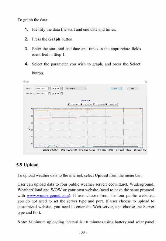
To graph the data:
1. Identify the data file start and end date and times.
2. Press the Graph button.
3. Enter the start and end date and times in the appropriate fieldsidentified in Step 1.
4. Select the parameter you wish to graph, and press the Select
button.
5.9 Upload
To upload weather data to the internet, select Upload from the menu bar.
User can upload data to four public weather server: ecowitt.net, Wuderground,WeatherCloud and WOW or your own website (need to have the same protocolwith www.wundergound.com). If user choose from the four public websites,you do not need to set the server type and port. If user choose to upload tocustomized website, you need to enter the Web server, and choose the Servertype and Port.
Note: Minimum uploading interval is 10 minutes using battery and solar panel

- 36 -
in the package. If you use USB charger minimum uploading canbe 3 minutes. Itwon’t upload data to internet if you set interval to “0”.
Operations tips for uploading to ecowitt.net:
1.Go to the Upload page - set the Activity to Enable upload - click the button of"Add To Ecowitt"
2.Register on the www.ecowitt.net and then go to Devices to add the device.When selecting MAC/IMEI, please select IMEI and input the numbers from thePC software.
3.If uploaded successfully, ecowitt logo icon will appear on the PC software:

- 37 -
If you have any problem during the operation, please contact ourcustomer service for help.
5.10 Update Firmware
After install the PC software and open on computer, if there is new versionfirmware available, a dialog box will pop up indicating to upgrade or not.Click ”OK" will guide to upgrade the firmware.
System will download firmware first. After that it upgrades the new firmware.
During upgrading:

- 38 -
5.11 Factory Reset
Press Factory Reset button, below indication will be displayed:
Click ”OK" to return to factory default settings or click ”cancel” to cancel thefactory reset.

- 39 -
6 Mobile Phone Control via SMS
Users can check current weather data by sending SMS to the receiver terminalvia any of the 3 pre-programmed mobile numbers (only to be programmed withPC software, please refer to USB configure tool Operation).
SMS command list:
1. Current : send current weather data
2. MAX : send Maximum value recorded
3. MIN : send Minimum value recorded
4. Interval: send interval value setting
5. Status: send system status, like battery voltage, sensor status,network condition
6. Alarm ON: turn on sending alarm SMS function
7. Alarm Off: turn off sending alarm SMS function.
8. Reboot: Reboot the device
1. View current weather Data: Current
Sending a SMS of “Current” to the station will trigger a command to theweather station to send its latest weather data to your mobile phone viaSMS.
Answer from the weather station is as shown in below figure by 2messages:

- 40 -
2. View Max/Min weather data record:MAX::MIN
Sending SMS of “Max” or “Min” to weather station triggers sendingrecorded maximum value to your mobile phone.
The SMS from station looks like this:
3. Check programmed interval time: Interval
Send SMS “Interval” to station triggers sending its pre-programmedinterval value stored on station, it is mainly for reminding the valueprogrammed on station. The reply of SMS from station is like this:

- 41 -
Alarm: The interval of alarm repeating. A repeated alarm will only be sentafter this interval
Send: The interval of sending current weather data by SMS.
Save: The logging history data interval that to be saved on Mirco SD Card.
Updata: The interval of uploading data to internet.
4. Enable or disable alarm function: Alarm On :: Alarm Off
Send SMS “Alarm On” or “Alarm Off” will enable or disable the pre-programmed alarm function. Station will reply “Alarm disable” or
“Alarm Enable” to confirm.
5. Check weather station status: Status
Send SMS “Status” to station will trigger station to send back currentcondition of the station system. The SMS from station looks like this:
(In)Transmitter=normal The weather station indoor sensor isfunctioning without errors
(In)Transmitter =error An error has occurred, check the indoorsensor

- 42 -
(Out) Transmitter=normal The weather station outdoor sensoris functioning without errors
(Out) Transmitter =error An error has occurred, check theoutdoor sensor
Network=normal The weather station network is functioningwithout errors
Network= error An error has occurred, check the weatherstation SIM card.
SD card= normal The SD card is functioning without errors
SD card=not exist No Micro SD card is detected or available.
Check the weather station and insert asuitable Micro SD card.
Battery=3.5V The voltage of battery in console is 3.5V
6.1 SMS data from station
Main base station will send weather, alarm or critical condition tosystem value regularly via SMS. Below are the SMS received lookedlike:

- 43 -
6.2 Low Power alarm
The receiver unit constantly monitors the battery voltage. An SMS alert will besent to pre-programmed phone when battery voltage drops below 3.5V:
When battery voltage drops further and below 3.3v, system will suspendpushing data to weather server. SMS below will be sent.
All functions will be suspended when battery voltage drops below 3V.When battery is charged to 3.9v or even higher, system will be activatedby sending this SMS:
If system has restarted after reset, a startup SMS will be sent:

- 44 -
7 Weather Server
The receiver unit is capable of sending your sensor data to select internet-based weather services and your own website(need to have the same protocolwith www.wundergound.com). The supported services are shown in the tablebelow:
Service Website Description
EcowittWeather
https://www.ecowitt.net Ecowitt is a new weather server thatcan host a bunch of sensors that otherservices don’t support.
WeatherUnderground
https://www.wunderground.
com
Weather Underground is a freeweather hosting service that allowsyou to send and view your weatherstation data real-time, view graphs andgauges, import text data for moredetailed analysis and use iPhone, iPadand Android applications available atWunderground.com. WeatherUnderground is a subsidiary of TheWeather Channel and IBM.
WOW http://wow.metoffice.gov.uk/ WOW is a UK based weatherobservation website.
WeatherCloud
https://weathercloud.net Weathercloud is a real-time weathersocial network formed by observersfrom around the world.
CustomizedWebsite
Supports uploading to your customizedwebsite, if the website has the sameprotocol with Wunderground orEcowitt

- 45 -
7.1 Viewing data on ecowitt.net
You can observe your sensor’s data by using the ecowitt.net web site. You willuse a URL like this one, where your station ID replaces the text “STATIONID”.https://www.ecowitt.net/home/index?id=STATIONID
It will show a page such as this, where you can look at today’s data andhistorical data as well.
Dashboard

- 46 -
Graph display
List display

- 47 -
Weather Map
Email Alerts

- 48 -
7.2 Registering with and using wunderground.com
1. Visit Wunderground.com and click Join as the right top arrow indicates andselect the select the Sign up for free option.
2. Click More and select Add Weather Station to register your station

- 49 -
3. Click verify location and fill out the form.
After submitting the form, you will see the following:

- 50 -
4. Take note of the station ID and key/password and enter it in the PCsoftware.
7.3 Viewing data on wunderground.com
The most basic way to observe your weather station’s data is by using thewunderground.com web site. You will use a URL like this one, where yourstation ID replaces the text “STATIONID”:http://www.wunderground.com/personal-weather-station/dashboard?ID=STATIONID
It will show a page such as this, where you can look at today’s data andhistorical data as well:

- 51 -
There are also some very useful mobile apps. The URLs provided here go to theWeb version of the application pages. You can also find them directly from theiOS or Google Play stores:
WunderStation: iPad application for viewing your station’s data and graphs
https://itunes.apple.com/us/app/wunderstation-weather-from-your-neighborhood/id906099986

- 52 -
WU Storm: iPad and iPhone application for viewing radar images, animatedwind, cloud coverage and detailed forecast, and PWS station data
https://itunes.apple.com/us/app/wu-storm/id955957721
Weather Underground: Forecast: iOS and Android application forforecasts
https://itunes.apple.com/us/app/weather-underground-forecast/id486154808https://play.google.com/store/apps/details?id=com.wunderground.android.weather&hl=en

- 53 -
PWS Weather Station Monitor: View weather conditions in yourneighborhood, or even right in your own backyard. Connects towunderground.com
https://itunes.apple.com/us/app/pws-weather-station-monitor/id713705929

- 54 -
7.4 Registering with and using Weathercloud
To register with Weathercloud follow these steps:
1. Visit weathercloud.net and enter your Username, Email and Password tosign up.
2. Follow the indications to verify your account.
3. You will then be prompted to add a device/ Select “Create device” andenter your station’s information:

- 55 -
4. After registering your station, take note of the “Weathercloud ID” and“Key” presented to you. Enter these values in the PC software:
7.5 Registering with Weather Observations Website (WOW)
To have your weather station upload data to the Met Office’s WOW siteyou will need to complete the following steps:
1. Sign Up with WOW
2. Confirm your email with WOW
3. Login to WOW
4. Create/Set up a new WOW site
1. Sign up with WOW
Navigate your browser to http://wow.metoffice.gov.uk. On the top-right side ofthe resulting page you will see menu options. Click “Sign Up”.
You will be presented with the screen below where you will choose to eithercreate a new account or use an already existing account. Click the desiredoption.

- 56 -
If you chose “New Account” you will be presented with a form to fill out:
The actual form is longer, but all questions should be self-explanatory.Complete and submit the form. You will receive the following notice oncompletion:

- 57 -
2. Confirm email with WOW
Now wait for the email to arrive and click the link in that email to confirm youremail address.
3. Login with WOW
Follow instructions on the screen and login to the site.
Create/Set up a new WOW site
Once you are logged in you will need to create a new WOW site. “Sites” are themeans by which WOW organizes weather data the you contribute. Basically,WOW builds a personal web site for your weather station. Associated with theweb site is two items you will need to allow uploading of data:
Site ID: This is an arbitrary number that is used to distinguish your site fromanother. This number appears (in brackets) next to or underneath the name ofyour site on the site information page, for example: 6a571450-df53-e611-9401-0003ff5987fd
Authentication Key: This is a 6-digit number that is used to ensure data iscoming from you and not another user.
Begin setting up a new site by clicking “Enter a Site”:
You will be presented with a form where you detail your station’s location anda bunch of other settings related to how you wish the site to operate. After youcomplete the setup, you should see:

- 58 -
Make sure you are (still) logged in to the WOW site. Login as necessary. Nowclick on “My Sites” in the navigation bar at the top. If you have only 1 site, youwill now be shown its page. If you have multiple, you will have to choose thecorrect one first. On this page, on the right side you will find the site id justbelow the map:
You will also need to establish a unique 6 digits PIN code that you should keepsecret. It is the “Authentication Key.” Setup this number by clicking on “EditSite”) and filling out the with a 6-digit number of your choice:
You will need both “Site ID” and “Authentication Key” to setup the uploadconfiguration for WOW in the PC software.

- 59 -
8 Maintenance
1. Clean Rain GaugeCheck the rain gauge every 3 months. Rotate the funnel counter-clockwiseand lift it up. Clean the funnel and bucket with a damp cloth to remove anydirt, debris and insects. Spray the array lightly with insecticide, if there’s abug infestation.
Figure 60: Rain gauge installation and maintenance
2. Clean Solar Radiation Sensor and Solar PanelThe solar radiation sensor and solar panel of the outdoor sensor array need tobe cleaned with a non-abrasive slightly damp cloth every 3 months.

- 60 -
3. Replacing Batteries RegularlyBatteries of the outdoor sensor array need to be replaced every 1-2 yearsfor environmental friendly. In serious environments, check the batteriesevery 3 months and apply a corrosion preventing compound(not included)on the battery terminals for protection.
4. To Prevent Snow build upIn snowy days, use anti-icing silicon spray on the top of the weather stationto prevent snow build up.

- 61 -
9 Troubleshooting Guide
Problem Solution
Outdoor data nottransmitted.
The outdoor sensor array may have initiated properly andthe data is registered by the console as invalid, and theconsole must be reset. Press the reset button as describedin Initial Receiver Unit Set Up
Take out the batteries and wait one minute, while coveringthe solar panel to drain the voltage.
Put batteries back in and resync the console with the sensorarray about 10 feet away.
The LED next to the battery compartment will flash every16 seconds. If the LED is not flashing every 16seconds…
Replace the batteries in the outside sensor array.
If the batteries were recently replaced, check the polarity.If the sensor is flashing every 16 seconds, proceed to thenext step.
There may be a temporary loss of communication due toreception loss related to interference or other locationfactors,
or the batteries may have been changed in the sensor arrayand the console has not been reset. The solution may be assimple as powering down and up the console (remove ACpower and batteries, wait 10 seconds, and reinsert ACpower and batteries).
Temperaturesensor reads toohigh in the daytime.
Make certain that the sensor array is not too close to heatgenerating sources or strictures, such as buildings,pavement, walls or air conditioning units.
Use the calibration feature to offset installation issuesrelated to radiant heat sources.

- 62 -
Problem Solution
Relative pressuredoes not agree withofficial reportingstation
You may be viewing the absolute pressure, not therelative pressure.
Select the relative pressure. Make sure you properlycalibrate the sensor to an official local weather station.
Rain gauge reportsrain when it is notraining
An unstable mounting solution (sway in the mountingpole) may result in the tipping bucket incorrectlyincrementing rainfall. Make sure you have a stable,level mounting solution.
Data not reporting toWunderground.com
1. Confirm your password or key is correct. It isthe password you registered onWunderground.com. YourWunderground.compassword cannot begin with a non-alphanumericcharacter (a limitation of Wundeground.com, notthe station). Example, $oewkrf is not a validpassword, but oewkrf$ is valid.
2. Confirm your station ID is correct. The stationID is all caps, and the most common issue issubstituting an O for a 0 (or visa versa).Example, KAZPHOEN11, not KAZPH0EN11
3. Make sure the date and time is correct on the PCsoftware. If incorrect, you may be reporting olddata, not real time data.
4. Check your router firewall settings. Theconsole sends data via Port 80.

- 63 -
10 Specifications
Outdoor data
RF working distance in open field: 100m(300 feet)Frequency: 915/868/433MHz (915MHz for North America, 868MHz forEurope, 433 for other areas)Temperature range: -40˚C--60˚C(-40℉ to +140℉) Resolution: 0.1˚C (0.2℉)Measuring range rel. humidity: 1%~99%Rain volume display: 0 – 9999mm (show --- if outside range)Rain Resolution: 0.254mm/0.01inchRain Accuracy: <8%Wind speed: 0-160km/h (0~100mph) (show --- if outside range)Light: 0-300000 luxUV index: 0-15(0-2000 w/m2)Sensor update interval: 16 secWater proof level: IPX3
Indoor data
Measuring interval: 61 secIndoor temperature range: -40˚C--60˚C(-40℉ to +140℉)Resolution: 0.1˚C (0.2℉)
Measuring range rel. humidity: 10%~99%Resolution: 1%Measuring range air pressure: 300-1100hPa (8.85-32.5inHg)Accuracy: +/-3hpa under 700-1100hPaResolution: 0.1hPa (0.01inHg)Power consumptionBase station: 1x 18650 battery (included) or USB charger (USB cableincluded)Solar panel as backup power: Voc: 6.2V, Isc : 500mA, Size:195*138mmIndoor sensor: 2xAA Alkaline batteries (not included)Outdoor sensor: 2xAA Alkaline batteries (not included)Battery life: Minimum 12 months for indoor & outdoor sensor

- 64 -
11 Warranty Information
We disclaim any responsibility for any technical error or printing error, ortheir consequences.
All trademarks and patents are recognized.
We provide a 1-year limited warranty on this product against manufacturingdefects in materials and workmanship.
This limited warranty begins on the original date of purchase, is valid only onproducts purchased and only to the original purchaser of this product. Toreceive warranty service, the purchaser must contact us for problemdetermination and service procedures.
This warranty covers only actual defects within the product itself, and does notcover the cost of installation or removal from a fixed installation, normal set-upor adjustments, claims based on misrepresentation by the seller or performancevariations resulting from installation-related circumstances.
Please help in the preservation of the environment and return usedbatteries to an authorized depot.
All rights reserved. This handbook must not be reproduced in any form,even in excerpts, or duplicated or processed using electronic, mechanicalor chemical procedures without written permission of the publisher.