for chris rodriguez, p.e. hdr project manager · b.4.b: hydrogen sulfide treatment vessels-please...
TRANSCRIPT

TO: ALL HOLDERS OF CONTRACT DOCUMENTS FOR:
City of Santa Fe, New Mexico
Wastewater Management Division
Anaerobic Digester Project
BID ‘18/08/B
The following Addendum shall be incorporated into the Contract Documents for the above referenced
project.
ADDENDUM NO. TWO (2)
February 13, 2018
Questions / Clarifications:
1. Questions to Specification Section 46 73 36.
1. Section 46 73 36, 1.3, B.11.b&f: There is no known certified pressure drop calculations to
determine the pressure drop thru the media. Please verify what this will be used for.
Response: We need to know what the pressure drop across the vessel will be so that we make
sure we have enough pressure to feed the blower.
2. Section 46 73 36, 1.3, B.11.d: The moisture separated is integral to the heat exchanger.
Response: The specification has been modified by this addendum to clarify there is no separate
moisture separator.
3. Section 46 73 36, 2.2: This paragraph lists two hydrogen sulfide scrubbers. 2.4.b.1 Also lists two
hydrogen sulfide vessels but drawings 00D-03 and 03D-01 show one H2S vessel. Please confirm
how many vessels are required.
Response: Yes, there is only one vessel. The specification has been modified by this addendum.
4. Section 46 73 36, 2.4.B- Components- Hydrogen Sulfide Treatment Skid
a. B.4.b: Hydrogen Sulfide Treatment Vessels-Please switch API to ASME standards.
b. B.4.d: Hydrogen Sulfide Treatment Vessels- Is a p-trap style drain acceptable in place of
a timer controlled electrically actuated drip trap.
c. B.5: Air Compressors- Is it acceptable to supply a blower for supply of regeneration air?
All blowers and compressors shall be 480 V power.
d. B.7.a: Support frame. This states the vessels shall be supported on a stainless steel frame,
is this statement requiring the vessel(s) be skid mounted, or is this statement referring to
the vessel legs. If a skid is not required please remove all reference to hydrogen sulfide
treatment (skid).
e. B.8.c: Accessories- Provide two 110 V, electrical outlets - If the system is not skid
mounted then these should be contractor supplied. If the system is skid mounted the
outlets will need to be powered by local lighting panel.
For Chris Rodriguez, P.E.
HDR Project Manager
City of Santa Fe, NM Wastewater Management Division Anaerobic Digester Project BID '18/08/B
Addendum No. 02February 13, 2018
Page 1 of 44
f. B.9.a: Iron Sponge Media- Should be clarified that the initial charge of media will be
supplied but the vessel will not be shipped with the initial charge inside. Installation
contractor is responsible for loading the media into vessel(s).
g. B.9.b: Iron Sponge Media
i. Does the 6 month media life requirement have to be met using the average or
maximum design requirements?
ii. Does the 6 month media life assume regeneration of media?
iii. If we have to design to the max design requirements the 6 month media life is not
obtainable.
Responses:
a. OK
b. No, provide drip trap
c. Blower as specified in B.5. 110VAC
d. Delete skid from spec.
e. Change B.8.c. to indicate installation contractor to provide.
f. Revise to indicate Installation Contractor to provide media.
g. See below:
i. Yes, use average.
ii. No.
iii. Do not use max.
5. Section 46 73 36, 2.4.C- Digester Gas Moisture Removal and Compression Skid is worded such
that the moisture removal is before the blower, but in drawing 00D-03 the compressor is located
before the moisture removal. Please verify the sequence of the equipment.
Response: Blower then moisture removal. Refer to P&IDs for order..
6. Section 46 73 36, 2.4.C.5- Components- Digester Gas Moisture Removal and Compression Skid.
a. C.5: Digester Gas Cooling Heat exchanger- this states that the exchanger will only cool
the gas to 40 degrees after compression, it does not state needing to reheat back to 80F
that section 2.3.B Performance and design requirements states discharge temperature.
Please clarify that a dual core exchanger is needed to cool to 40F and then reheated to 80.
Please refer to the below verbiage.
i. Dual Core Heat Exchanger
1. Stage 1 - Gas to gas plate/fin core- Materials of constructions shall be
aluminum plate and fins
2. Stage 2 - Gas to glycol fin/tube core
3. Materials of construction shall be aluminum fins on 304L stainless steel
tubes
4. Mounted in single 304 stainless steel housing
5. 150# ANSI B16.5 inlet and outlet connections
6. All condensation generated during cooling will be removed inside the
heat exchanger housing
7. Level switch mounted on the housing to warn of drain failure
8. RTD mounted on the housing to verify the coldest temperature that the
gas reaches
9. Bottom drain with strainer, float drain, manual bypass and piping
City of Santa Fe, NM Wastewater Management Division Anaerobic Digester Project BID '18/08/B
Addendum No. 02February 13, 2018
Page 2 of 44

b. C.6.a Moisture Separator is integral to the heat exchanger, please remove.
c. C.7.a Digester Gas Pressure Booster Blower- Drawing 00D-03 shows two blowers but
this section states only one blower. Please clarify.
d. C.8.b Booster Blower inlet filters - We normally provide condensate pump operated via
level switches. Please verify if this is acceptable.
Responses:
a. Yes, include reheat to 80F.
i. Revise spec to match i.
b. Ok.
c. Provide 1 blower.
d. Yes, it is acceptable.
7. Section 46 73 36, 2.4.E- Components- Siloxane Scrubber Skid.
a. Is 304 SS construction acceptable for siloxane scrubber vessels and piping?
b. E.2.e- Is it intended the siloxane vessels be skid mounted as shown in drawing 03D-02 or
free standing as stated here?
c. E.3.a- Is this statement requiring the vessel(s) be skid mounted, or is this statement
referring to the vessel legs or skirt? If a skid is required is powder coated steel acceptable.
d. E.5- Accessories- Provide two 110 V, electrical outlets - If the system is not skid
mounted then these should be contractor supplied. If the system is skid mounted the
outlets will need to be powered by local lighting panel.
e. E.6.c- Siloxane Scrubber media- Media life can not be accurately calculated without
VOC. In order to estimate media life speciated siloxane and VOC data is needed. At 40
mg/m3 (total as Si) it is not possible to achieve a 6 month media life.
Responses:
e. Yes SS is acceptable.
f. Skid mounted.
g. Skid mounted, powder coated is acceptable.
h. Skid mounted, provide outlets.
i. Change siloxane to 8 mg/m3 Si., VOCs are less than 1 ppmv.
8. Section 46 73 36, 2.4.I.1 -Surface Preparation and Field Painting- Is powder coated steel
acceptable.
Response: Yes.
9. Section 46 73 36, 3.2.A.1 – The digester gas treatment system does not have a pressurized oil
system, please remove the simulation of low oil pressure.
Response: Ok.
10. Section 46 73 36, 3.2.A.2 – Blower manufacturer does not offer certification of install, this is
certified by Unison.
Response: Ok.
City of Santa Fe, NM Wastewater Management Division Anaerobic Digester Project BID '18/08/B
Addendum No. 02February 13, 2018
Page 3 of 44

11. Section 46 73 36, 3.2.B.2-Performance Test- At 9 months the vessels will not contain original
media for either iron sponge or siloxane.
Response: The specification has been modified by this addendum to reduce the time until the 2nd
test.
12. Section 46 73 36, 3.2.B.4-Please remove this statement as calculations show that it is not possible
to have a 6 month media life at maximum design conditions.
Response: See comments above about VOC and siloxane concentrations. The statement will be
left in the specification.
13. Section 46 73 36, 3.2.B.5- Can the treatment system vendor assume that the samples will be taken
by the owner?
Response: No, vendor shall be responsible for all sampling and testing.
14. Section 46 73 36, 3.2C.1 – Service Support – Please remove this section as the media change out
intervals are unknown and cannot be accurately calculated due to constantly varying raw gas
quality. Due to the constantly changing raw gas quality process guarantees are not available.
Response: Specification has been modified by this addendum. Reference to performance
guarantee will be removed, however, service support based on 6 month interval media
replacement will remain, with clarification that if media replacement frequency varies from 6
months then adjustment to support will be agreed to.
15. Drawing 03D-02 references a premanufactured building enclosure. Who will provide this?
Response: Enclosure to be provided by supplier. The specification has been modified by this
addendum.
2. Question: The P&ID drawings(06Y-01 thru 06Y-03) do not indicate sizes of the process lines that
require flow meters. Also, all flow meters are shown as Mag Meters, however per the instrument list
provided in the specifications a couple of them are called out as Thermal Dispersion. There also
seems to be some discrepancy between the tag numbers of the FIT’s as shown on the P&ID’s and
what I can find on the plan drawings. Any way that HDR can confirm the flow meter sizes based on
the tag numbers? If not I’ll forward the required flow rates to the vendors and have them determine
the needed sizes based on the low and high limits in the instrument list, although I’d prefer not to do
that.
Response: The flowmeters on the digester gas lines are thermal dispersion flowmeters as called out
in Spec 40 91 10. FIT-101 and 102 shown on 06Y-01 are magnetic flowmeters that need to be
provided per Spec 40 91 10. P&IDs do not show lines sizes, Contractor will need to refer to process
and piping drawings for line size and location information.
3. Specification Section 40 90 05.3.19.E- Per this section Digester Mixing pumps will be controlled Via
VFD, yet this isn’t indicated on the electrical drawings. Please confirm.
Response: Digester mixing chopper pumps shall have VFDs.
City of Santa Fe, NM Wastewater Management Division Anaerobic Digester Project BID '18/08/B
Addendum No. 02February 13, 2018
Page 4 of 44

4. Where does Spec Section 07 26 00, Under Slab Vapor Retarder apply? Is vapor retired required
anywhere?
Response: Specification applies to vapor retarder underneath equipment building slab.
5. Where does Spec Section 09 67 00, Epoxy Flooring System apply?
Response: Specification applies to coating the equipment building and gas room floors.
6. Where does Spec Section 12 36 63, Solid Surface Fabrications apply?
Specification is for countertops in administration building, details 1 & 4 on sheet 05A-04.
7. Where does Spec Section 07 14 00, Fluid Applied Waterproofing apply?
Response: Specification applies to all concrete masonry (CMU).
8. Questions to Section 46 33 13 (Polymer Blending Unit)
• Question: Paragraph 2.2.C.5.a references a Variable Frequency Drive but 5.e states the pump is
Solid-state solenoid actuated. Clarification: No VFD is required with solenoid actuated pumps.
Response: Will be reviewed during the shop drawing review process.
• Question: Paragraph 2.2.8.a – “Liquid polymer to be pre‐mixed and stored in square
configuration tote type polyethylene tanks.” Request of Clarification: We assume this refers to the
storage of neat polymer product in totes, not storage of diluted polymer.
Response: Correct, this is neat polymer storage. There are no requirements for additional
polymer storage for this project.
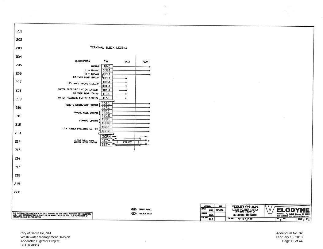
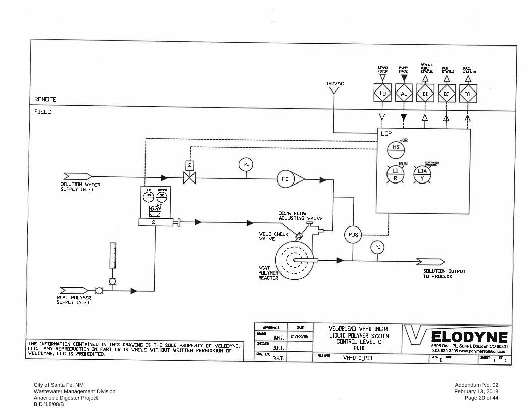
• Question: Paragraph 2.3.F.2.b.5 – requires pump speed output from the Polymer Blend Unit
control panel. Section 46 76 21 Paragraph 2.4.C.1.b.7.a.3 also requires this, but it does not appear
to be shown the BFP Control Panel Drawing (Sheet 04Y-010.) Clarification: We are providing
our best interpretation meeting the intent of the specification.
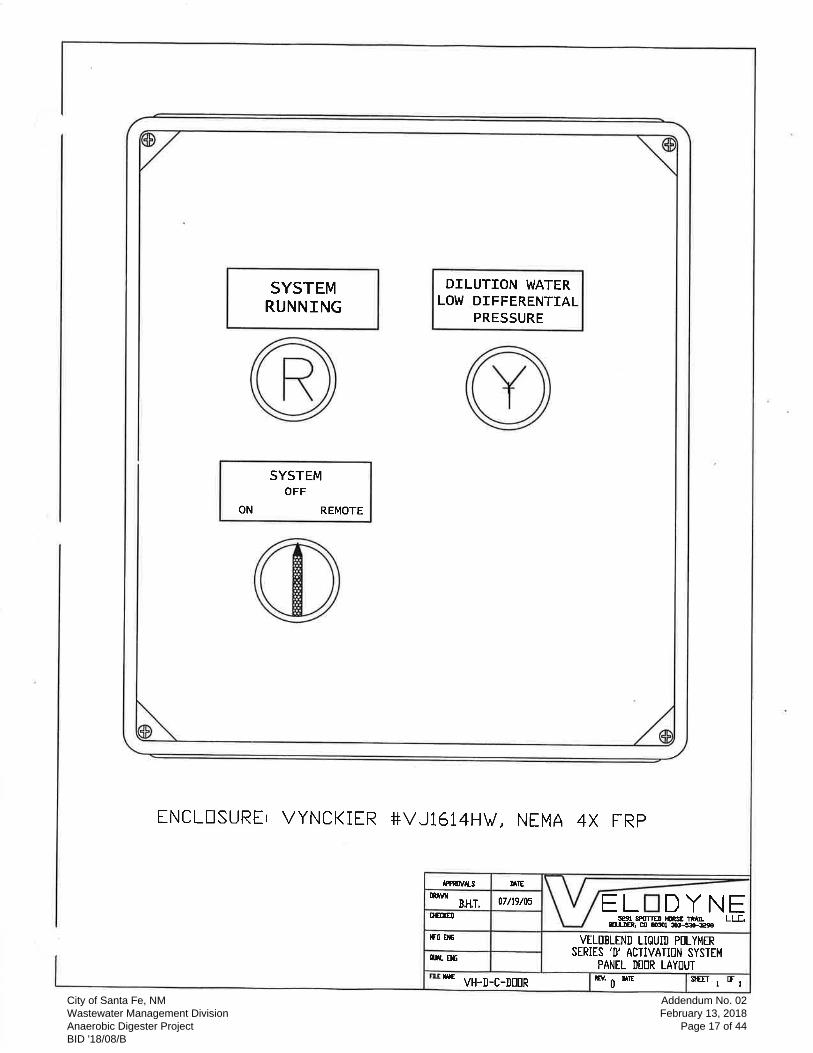
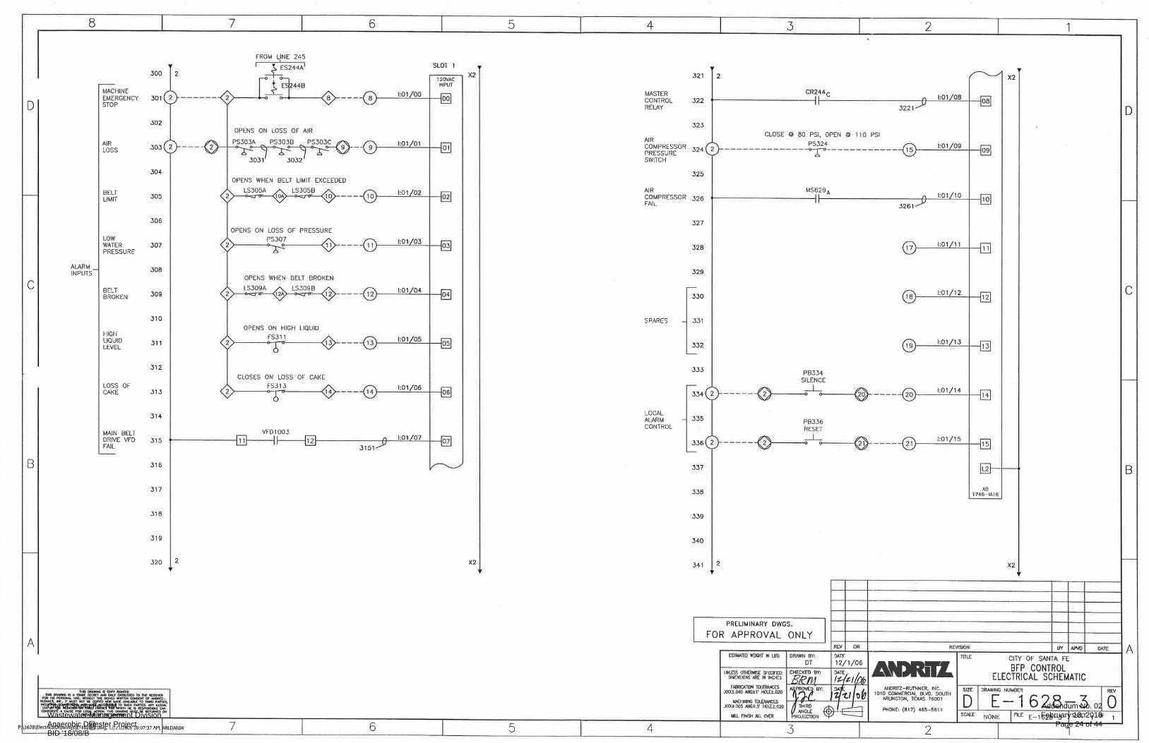
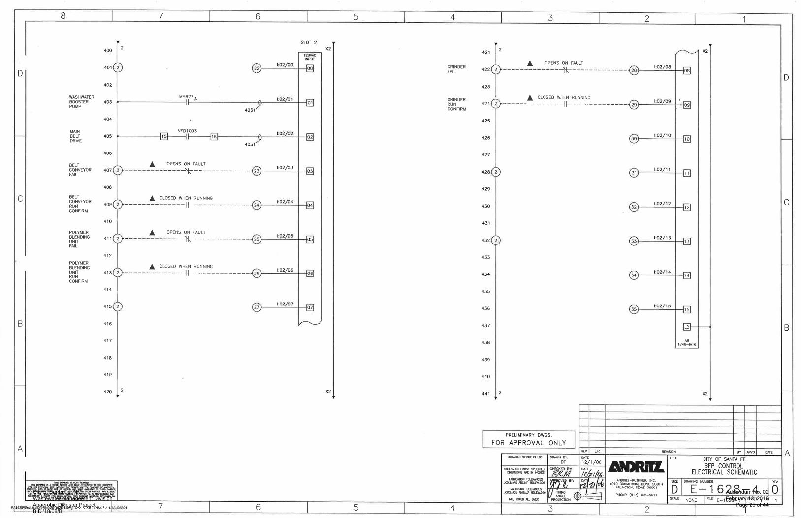
Response: Provide new control panel to match existing control panels. Information of existing
control panel is included on this addendum for informational purposes.
• Question: If a local panel is required for operator interface, what functions are desired: pilot
devices or OIT.
Response: Local control panel shall include an OIT. Specification for local panel is included in
this addendum.
• Question: Similarly, what operator interfaces are desired on the Main panel?
Response: Provide operator interface OIT on main control panel as specified. Note that the new
control panel shall be SST NEMA 4X.
9. Questions to Section 46 76 21 (Belt Filter Press)
• Question: Paragraph 1.2.A.4.a: Clarification: The equipment will meet SSPC-8
Response: Surface prep shall meet all specifications.
• Question: Paragraph 2.5.B.7: Clarification: The equipment to be supplied by Alfa Laval will
have a minimum cross-section moment of inertia of 25.3 in (4) that will meet the intent of the
specification.
Response: Moment of inertial shall meet specifications.
City of Santa Fe, NM Wastewater Management Division Anaerobic Digester Project BID '18/08/B
Addendum No. 02February 13, 2018
Page 5 of 44

• Paragraph 2.5.F.2.a: Injection rings: Number and size: 4 rings at 6 inches. Request of
Clarification: Is this what you are asking for?
Response: Should be one (1) ring with 4 injection points at 6 inches.
• Question: Paragraph 2.5.P.2.a: Clarification: The strength of the seams has to be less or equal to
the belt.
Response: Seam strength shall be in accordance with specifications and manufacturers
recommendations.
• Question: Paragraph 2.5.T.1: Clarification: Sludge press connection will be 6 IN ANSI 150#
Response: Noted, will be reviewed during the shop drawing review process.
• Question: Paragraph 3.1.E: Spool pieces. Request of Clarification: How many spool pieces?
Response: Refer to drawings. The injection ring is to be installed in front of the static mixer.
10. Comments to Section 46 73 42 – Digester Heating Heat Exchanger
• Question: Paragraph 2.2.A.5. At 2000 KBth/hr , 250 gpm and 95 inlet temp the outlet temp is
111F, not 101F as indicated in the specification. We feel that 111 F is not an ideal outlet
temperature as the Delta T is above our recommended 10 F. Higher Delta T values can shock the
bacteria. We recommend an increase in sludge flow rate to 400 gpm to reduce the outlet
temperature to 105F.
Response: Heat exchangers are on three way valve loops, so temperature inlet is controlled.
• Question: Paragraph 2.2.A.6.a. If you have more than 100 gpm of water available we could
reduce the size of the heat exchanger appreciably.
Response: Flow will remain as specified.
• Question: Paragraph 2.2.A.6.c. If the allowable Delta P could be raised from .7 psi to 2 psi as the
original heat exchangers are, we could reduce the size of the heat exchanger.
Response: Head will remain as specified.
• Paragraph 2.4.D.2. Drains will be 3000# couplings, plugged.
Response: Will be reviewed during the shop drawing review process.
• Paragraph 2.4.D.4. Water drains will be 3/8”. We do not supply the valves.
Response: General Contractor to coordinate.
11. We are requesting information as to how to acquire a list of plan holders in order to get pricing to all
bidding contractors. Since specifications can be accessed through the City of Santa Fe website, in
addition to the Academy Reprographics Online Planroom, we have only been able to access Plan
holders that are registered with Academy Reprographics. Is there a manner to insure that we have a
list of all bidding General Contractors?
Response: There is only the plan holders list on Academy Reprographics. Suppliers and
subcontractors will need to coordinate with general contractors bidding the project. The pre-bid
conference sign in list was provided in Addendum No. 1. The pre-bid conference was non-mandatory
and other contractors may submit a bid.
City of Santa Fe, NM Wastewater Management Division Anaerobic Digester Project BID '18/08/B
Addendum No. 02February 13, 2018
Page 6 of 44

12. Does all of the structural steel on the digester domes get field painted? ie (underside of steel dome,
ceiling radial beams, slide brackets, exterior steel overflow trough).
Response: Yes, all steel on digester dome shall require surface preparation and high performance
industrial coating in the field. Refer to specification Section 46 73 16, 3.1 B. Overflow trough is
stainless steel.
13. Question: Does the interior concrete of digester coat?
Response: No.
14. Does the interior concrete ceiling in the Anaerobic Digester/Equipment Building paint?
Response: Yes.
15. Comments to Section 46 73 34 Digester Mixing System: External Pump Type.
• Question: 2.3. B Components: Piping and Fittings: Provide ductile iron suction and discharge
pipe and fittings between exterior pump and internal nozzles. Evoqua to clarify that the contractor
is to supply the pipe and fittings between the pump and pipe elbow that supplies the nozzles.
Response: Manufacturer to coordinate with Contractor.
• Question: 2.4. A. & B Nozzles: Shall be ASTM A536 glass lined cast ductile iron, with a
minimum 1” wall thickness or greater to protect against abrasive conditions, and a long straight
taper length of at least 12 inches. B. The fittings to be glass lined. Evoqua proposes to use our
standard single nozzle assemblies. Assemblies are ASTM A532 class II, Type C chrome iron with
minimum hardness of 450/550 Brinell, Mohs hardness of 5 throughout the entire nozzle wall.
Evoqua’s Jet Mix nozzles are minimum 1/2” wall thickness and due to the 28% chrome rock
crushing alloy, the Hi-Chrome nozzles are very durable and resistant to degradation. The elbows
or fittings will be glass lined per specification 2.4.B.
Response: Will be reviewed during the shop drawing review process.
• Question: 2.6.A .2. Impeller Shall be semi open type with pump out vanes to reduce seal area
pressure. Evoqua to clarify that Impeller shall be open type with sharpened vane edges
incorporated into the rear of the impeller to reduce seal area pressure.
Response: Manufacturer to verify.
• Question: 2.8 Painting and Coatings: A. See Section 09 96 00: Submerged units shall receive
paint system #24 or fusion bonded epoxy coating. Evoqua proposes to use a coating system of
Tnemec Series 69 Hi-Build Epoxoline. The prime coat shall have a minimum DFT of 3 – 5 mils
and intermediate and finish coat shall be applied with a DFT of 5+ mils each for a total coating
DFT of 13 – 16 mils. The nozzles shall be sandblasted in accordance with SSPC-SP6.Nozzles are
28% Hi Chrome cast alloy for resistance to corrosion under submerged conditions in the
anaerobic digester tanks.
Response: Coatings as specified are a minimum requirement.
16. Comments to Section 46 73 16 Digester Covers: Floating (Gasholder) Cover – Shell Type
• Question: 2.4 E: Combination Pressure Vacuum Relief Valve; See Specification 46 73 35.
Evoqua to clarify that the Combination Pressure Vacuum Relief Valve or valves are to be
provided by the contractor in the Digester Gas Equipment Section.
Response: General Contractor to coordinate. All gas equipment specified on the project shall be
provided by the same manufacturer.
City of Santa Fe, NM Wastewater Management Division Anaerobic Digester Project BID '18/08/B
Addendum No. 02February 13, 2018
Page 7 of 44
• Question: 2.4 F Flexible Hose for Gas. Evoqua to clarify that the flexible hose is to be provided
by contractor.
Response: General Contractor to coordinate.
17. The Equipment Building slab is detailed on Sheet 02S-01. There are two different slab control joints
called out (4/00S-03 and 8/00S-03). Please clarify which is required. Detail 4/00S-03 shows the
waterstop to required only at water bearing slabs, while Detail 8/00S-03 does not make that
distinction. Please clarify.
Response: Waterstop is not required for the equipment building slab. In detail 8 the control shall be
used at all joints as indicated and detail 4 shall be used at the one joint as indicated.
18. It appears from the slab control joints called out on Sheet 02S-01 and detailed on Sheet 00S-03 that
the slab must be placed in eight separate sections. Could a contractor choose to place the slab in one
placement and install sawcut control joints?
Response: It is acceptable to place slab in two sections. Detail 8 can be modified to be a sawed
control joint. Saw depth shall be 1 inch minimum filled with sealant. The construction joint shall be
provided per detail 4 on 00S-03 as indicated on the plan.
19. Detail 3/02S-05 details the corbel. Can Formsavers be used for the reinforcing, or could it be drilled
and epoxied into the wall?
Response: Formsavers may be used from the wall. Drilling and epoxying reinforcement is not
acceptable.
20. Detail 1/02S-06 calls for one mat of rebar in the floor slab of the Gas Equipment Building. However,
Detail 1/02S-08 shows two mats. Please clarify.
Response: One mat is required per the plan note At the turn down portion two mats is required. The
turn down shall be 6 inches and longitudinal shall match size and spacing of main reinforcement.
21. Detail A/02S-08 shows dowels and a 9” waterstop at the 1” expansion joint. Please provide the size
and spacing of the dowels required. Could form savers be used at the expansion end as well as at the
other end? Could the dowels be drilled and epoxied into the digester wall?
Response: Expansion joint shall be per 9/00S-03 with a 6” PVC waterstop. Dowel sleeve may be
provided at the digester wall as indicated. 6” Split Flange waterstop at digester wall may be used at
the contractor’s option.
22. The 9” waterstop shown on Detail A/02S-08 will extend 4.5” into the digester wall and interfere with
the digester wall reinforcing, which will have 2” of clearance. Please clarify. Could a retrofit
waterstop be used?
Response: Waterstop at this expansion joint shall be a 6” waterstop and steel clear cover may be
increased to 3 inches.
23. Spec. 03 09 00, section 2.3 calls for the concrete to be 4,000 psi, but Sheet 00S-01 calls for it to be
4,500 psi. Please clarify.
Response: Concrete shall be 4,500 psi per sheet 00S-01 for water containment structures only. All
other concrete shall be 4000 psi.
24. Please verify if fibers are required in water containment structures along with the Crystalline
Admixture.
Response: Only crystalline admixture is required for water containment structures not fibers. Fibers
are required for all other concrete besides water containment structures.
City of Santa Fe, NM Wastewater Management Division Anaerobic Digester Project BID '18/08/B
Addendum No. 02February 13, 2018
Page 8 of 44

25. Details 1 and 2/02A-06 show a 2” concrete topping over the precast concrete planks. Is there any
rebar or mesh required in the topping slab?
Response: WWF is required for the concrete topping. WWF shall be 6x6-W2.1xW2.1 or as required
by the precast hollowcore supplier.
26. Sheet 04Y-02 Shows the PLC in LCP-201 as a ControlLogix, Sheet 06Y-05 shows it as a Modicon
M580. Please clarify.
Response: It should be Modicon M580. Systems integrator to confirm that communication with
existing belt presses on DH+ network is possible with Modicon PLCs using Modbus TCP to DH+
gateway.
27. Note 1 on Sheet 06Y-05 describes all rack mounted components shall be owner furnished and
installed. Please confirm this is correct.
Response: Note should read “42U network rack”. All components on the rack are by systems
integrator.
28. Is LCP-402 on Sheet 06Y-05 the same as the Belt Press #3 control panel on Sheet 04Y-02, BFP-203
on Sheet 04Y-01 and as provided with the equipment under Section 46 76 21.
Response: Yes, LCP-402 is by belt press vendor
29. Sheet 06Y-05 shows LCP-401 as a CompactLogix, Sheet 04Y-02 shows it as a ControlLogix. Please
clarify.
Response: It should be Modicon M580.
30. Sheet 06Y-05 indicates LCP-401 is vendor supplied (V). Is this correct?
Response: No. This panel is by Systems Integrator
31. 04Y-01 shows I/O point between the Belt Filter Press Control Panel BFP-203 and LCP-401. Will the
two existing Belt Filter Presses have any interface with LCP-401 or the SCADA system?
Response: Existing belt filter press control panels will need to communicate as shown on 04Y-02
32. Sheet 04Y-01 shows the two existing and one new Belt Press Control Panels directly connected to the
existing Belt Feed Sludge Pump by DH+ and LCP-401 Connected to the SCADA system. Sheet 04Y-
02 shows a different connection for these panels, can we assume the connection as shown on 04Y-01
is correct?
Response: Sheet 04Y-02 shows correct communication. Sheet 04Y-01 is only a P&ID. Existing belt
filter press control panels will need to communicate as shown on 04Y-02
33. Will the supplier of the new Belt Filter Press PLC be responsible for all programming modifications
to the existing Local Belt Feed Sludge Pumps PLC and existing Belt Filter Press PLCs?
Response: Any modification to existing belt filter press PLCs will need to be done by systems
integrator. Supplier of new belt press will only provide new BFP control panel
34. Are FIT-201B and FIT-202B as shown on Sheet 04Y-01 existing or new?
Response: These are existing.
35. The schematics on 06E-04 and 06E-05 appear to show the Run, Off and Fail pilot lights in the MCC
for the Sludge Recirculation Pumps, Hot Water Pumps, Mixing Chopper Pumps and Sludge Transfer
Pumps. 06Y-01 and 06Y-02 shows these pilot lights in the Local Control Stations. Please clarify
which location or both is required for these pilot lights.
Response: Pilot lights are at both locations. On the MCC and at the local control station.
City of Santa Fe, NM Wastewater Management Division Anaerobic Digester Project BID '18/08/B
Addendum No. 02February 13, 2018
Page 9 of 44

36. Rockwell listed for MCC’s but not VFD’s. Would Rockwell, Alan Bradley MCC’s and VFD’s be
acceptable?
Response: Allen Bradley is included on this addendum as an acceptable manufacture.
37. Can you provide any information regarding the manufacturer and technical data on the existing Main
Switchboard located in the electrical yard? Data would be useful in order to provide the new
switchboard section for the cogeneration connection.
Response: The new switchboard which is to be connected to the main switchboard ass show on Sheet
00E-01 will be paid for out of the cogeneration power distribution allowance. New switch board
requirements will be determined after coordination with PNM has been completed. The ductbank,
conduits and conductors between the cogeneration system up to the existing main switchboard shall
be included in the cogeneration system bid amount.
38. Sheet 06E-02 shows designated “Keyed Note #2” at each of the MCCs (MCC-7 & MCC-8), yet there
is no Keyed Note #2 shown under the “Key Notes”, please clarify.
Response: Keyed Note #2 added.
39. Sheet 06Y-04, Keyed Note #1 Fiber Handhole. Refer to One-Line on this sheet, but it seems the one-
line is incomplete, please clarify.
Response: The correct one-line diagram is attached.
40. Please clarify if the fiber optic cabling is to be run in existing conduit, or if the routing shown on
drawing 06Y-04 is to be in all new conduit and handholes.
Response: All routing shown on 06Y-04 for fiber is all new conduit and handholes.
41. Please clarify if the cogeneration vendor is providing the cogeneration switchboard or if this is to be
provided by the electrical contractor.
Response: The new switchboard which is to be connected to the main switchboard ass show on Sheet
00E-01 will be paid for out of the cogeneration power distribution allowance. New switch board
requirements will be determined after coordination with PNM has been completed. The ductbank,
conduits and conductors between the cogeneration system up to the existing main switchboard shall
be included in the cogeneration system bid amount.
42. We are planning to provide a masonry price proposal to bidding GC(S) on PASEO WWTP project,
Santa Fe, NM. While browsing the plans, we were unable to locate the type of vertical rebar and it's
spacing. A clarification is appreciated.
Response: Wall reinforcing is called out on the Wall Reinforcement table on Drawing Sheet 02S-01.
43. The Exterior elevations on sheets 02A-03 and 02A-04 show the CMU to be splitface up to the color
band then smooth all the way to the top until you get to the colored split face Soldiered course.
However, the wall sections on sheet 02A-06 are drawn so that it is all to be split face block expect for
the single color band course at 8’ 0”. Please let us know how to proceed.
Response: CMU type shall be as shown on building elevations, sheets 02A-03 and 02A-04.
44. One other question came up concerning whether a safety selector valve was required for the two
PVR’s for the cover safety equipment. The drawing # 02D-04 shows individual plug valves. The Gas
Safety specs indicate SSV’s.
Response: A safety selector valve is intended to be provided and is corrected on this addendum.
City of Santa Fe, NM Wastewater Management Division Anaerobic Digester Project BID '18/08/B
Addendum No. 02February 13, 2018
Page 10 of 44
45. Specification 40 62 16 5 - A panel mounted OIT is shown to be installed in the Admin Bldg Control
Room. There are already two workstations located in the control room (ADM-WRK-001 & ADM-
WRK-002), does the OIT serve any different functionality than the workstations other than being
panel mounted?
Response: The panel mounted OIT in the Admin Bldg Control Room that is called in Spec 40 62 16 is
for the LCP-100. This will display this signals that are migrated from the existing control room
console which is being demo’ed. The OIT will also display signals hardwired to LCP-100.
46. Specification 40 90 05 3 - HMI/OIT Software Requirements - refers to Allen-Bradley PanelView Plus
6 HMI which conflicts with the type and quantity of OIT's specified in 40 62 16 5. Please confirm if
these are additional OIT's and/or supplied by equipment vendors not the System integrator.
Response: Panel mounted OITs quantities and manufacturer (Schneider Electric) are per Spec 40 62
16 2.5. OIT programming and graphics requirements are in Spec 40 62 16 2.14 D.
47. Drawing 04Y-02 - Please confirm all programming, control hardware and communications for both
old and new Belt Presses will be by the Belt Press vendor.
Response: Belt press vendor will only provide panel for new belt press. Panel LCP-401 is by
systems integrator as per specs. Systems Integrator is also responsible for establishing
communication from all 3 belt presses to the sludge pumps and LCP-201. There is an existing DH+
link from Belt press #1 and #2. The City’s preference is to use Modicon M340 or M580 PLCs.
Systems integrator will need to investigate the possibility of using DH+ to Modbus TCP gateways.
However in the event that DH+ to Modbus TCP gateways are not available (Prosoft is in the process
of making their gateway obsolete) the systems integrator might explore the use of ControlLogix for
bringing the belt press data over to LCP-201. Systems integrator will need to coordinate with the City
and provide documents and submittals before any procurement or panel fabrication.
48. Drawing 04Y-02 - The PLC's shown in LCP-201 and LCP-401 are Allen-Bradley ControlLogix. The
Specification 40 94 43 2 calls for Modicon M340/M580 which do not natively communicate via DH#
that is used by the existing Allen-Bradley SLC 5/04 PLC's. Please confirm PLC type and means of
communication with existing equipment.
Response: See response to question 47 above.
49. Drawing 04Y-02 -Several portions of specification 40 62 16 indicate the system integrator shall
supply equipment in LCP-401, this drawing indicates that LCP-401 is vendor furnished. Please
confirm that the control panels supplied by the system integrator are:
a) NIP-100
b) LCP-100
c) LCP-MAINT
d) LCP-201
Response: LCP-401 is by systems integrator. 04Y-02 does not say it is vendor furnished..
50. 6) Drawing 06Y-05 - A laser printer is shown in the Control Room, but not indicated in the
specifications. Please confirm if a printer needs to be supplied and if so provide specification.
Response: Provide laser printer. Specification added.
City of Santa Fe, NM Wastewater Management Division Anaerobic Digester Project BID '18/08/B
Addendum No. 02February 13, 2018
Page 11 of 44
Construction Contract Documents & Technical Specifications:
1. Specification Section 03 09 00 Concrete
• Page 8, 2.3 B. 1.; Add row to table: “All Concrete for Water Containment Structure, Normal
weight, 4,500 psi with Crystalline Admixture”.
2. Specification Section 08 70 00 Finish Hardware
• 3.3 A. Hardware Schedule, Add under Hardware Set # 03, Digester Gas Room Door 103A.
3. Specification Section 26 29 23 Variable Frequency Drives: Low Voltage
• Page 3, 21. A.; Add “4. Allen Bradley” to the acceptable manufacturers list.
4. Specification Section 40 90 05 Control Loop Descriptions
• Delete 3.2 A and 3.2 B and replace with “Not Used”.
5. Specification Section 40 62 16 Computer Network and Human Machine Interface (HMI) System
• Page 12, Add the following:
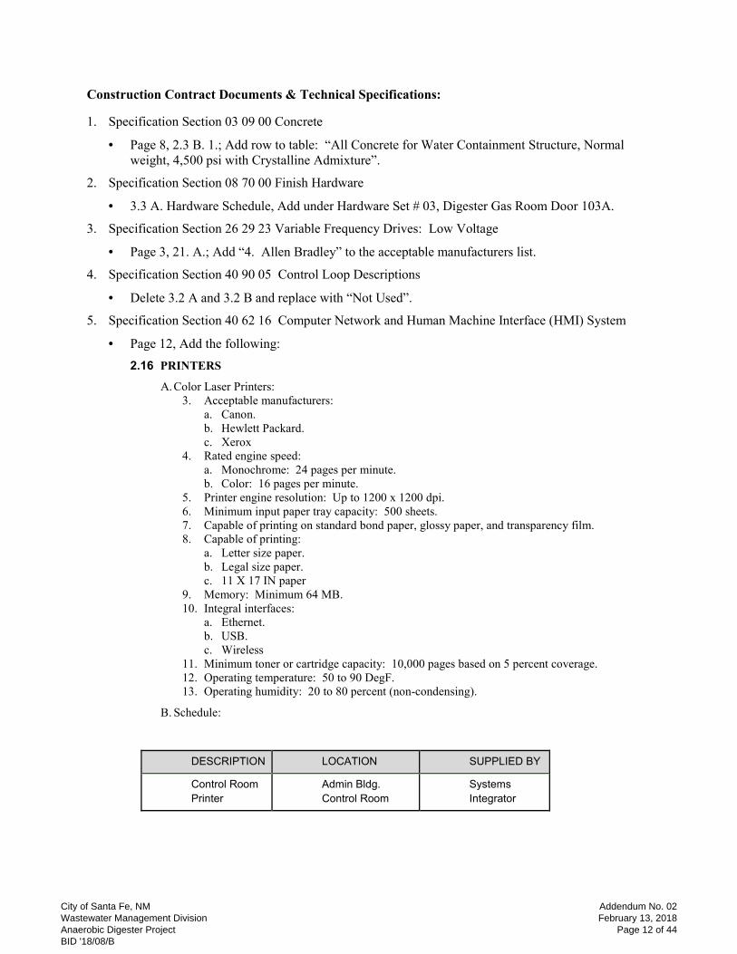
2.16 PRINTERS
A. Color Laser Printers:
3. Acceptable manufacturers:
a. Canon.
b. Hewlett Packard.
c. Xerox
4. Rated engine speed:
a. Monochrome: 24 pages per minute.
b. Color: 16 pages per minute.
5. Printer engine resolution: Up to 1200 x 1200 dpi.
6. Minimum input paper tray capacity: 500 sheets.
7. Capable of printing on standard bond paper, glossy paper, and transparency film.
8. Capable of printing:
a. Letter size paper.
b. Legal size paper.
c. 11 X 17 IN paper
9. Memory: Minimum 64 MB.
10. Integral interfaces:
a. Ethernet.
b. USB.
c. Wireless
11. Minimum toner or cartridge capacity: 10,000 pages based on 5 percent coverage.
12. Operating temperature: 50 to 90 DegF.
13. Operating humidity: 20 to 80 percent (non-condensing).
B. Schedule:
DESCRIPTION LOCATION SUPPLIED BY
Control Room
Printer
Admin Bldg.
Control Room
Systems
Integrator
City of Santa Fe, NM Wastewater Management Division Anaerobic Digester Project BID '18/08/B
Addendum No. 02February 13, 2018
Page 12 of 44
6. Specification Section 46 73 34 Digester Mixing System: External Pump Type
• Page 4, 2.7 A.; Add, “7. Electric, Variable Speed”.
7. Specification Section 46 73 36 Packaged Digester Gas Treatment System, Replace specification in
it’s entirety with the attached.
8. Specification Section 46 76 21 Belt Filter Press
• Page 3, 2.3 A. 1. a.; Change “1,900” to “700 – 1,600”;
• Page 3, 2.3 A. 1. C.; Change “15 percent” to “12 – 15 percent”.
• Page 3, 2.3 A. 1. H.; Change “15 – 20 lb/dry ton” to “20 – 15 lb/dry ton”.
• Page 6, 2.5 F. 2.; Change “4 rings” to “1 ring with 4 injection points”.
• Page 11, 3.2 B. 6; Change “Article 2.2” to “Article 2.3”.
• Page 5, Add the following:
3. Local Operator Panel:
a. All components in the panel shall be completely factory wired. All external control
connection points shall terminate on terminal blocks with ferrules on wire ends to
prevent fraying of wires during connection and servicing. There shall be a minimum of
10% spare terminal connection points supplied.
b. The enclosure shall be NEMA 4X, Type 304 stainless steel. The interior mounting panel
shall also be Type 304 stainless steel. Minimum dimensions shall be 30 IN high, 30 IN
wide, and 12 IN deep.
c. The panel shall contain an Operator Interface Terminal (OIT) with a color touchscreen
display, Allen-Bradley Panelview Plus 1500, with an Ethernet communication port.
d. On the face of the panel, in addition to the OIT, shall be the following:
1) Emergency stop push button.
2) Alarm horn and red halogen alarm light, with Acknowledge and Reset push
buttons.
e. The panel shall contain a 4 port industrial Ethernet switch, N-TRON Model 304TX.
f. The panel shall contain a ground fault type service receptacle.
g. Additional items shall be included with the panel as required.
h. All operator functions described below shall be provided through menus and function
keys on the OIT.
i. The OIT shall be capable of automatic or manual start/stop operations, as well as
provide display readings of the following: sludge and polymer actual flow rates, sludge
and polymer desired flow rates, fault monitoring, and pre-set and actual timing
operations, local/remote control status, and auto/manual control status, belt speed.
j. Control wire shall be #16 AWG minimum, shall conform to UL standards, and shall be
type MTW.
k. Each wire segment shall be numbered at each end using tubular heat shrinkable markers
with permanent mechanically stamped. The wire numbers shall correspond to those on
the wiring diagram. Wrap around or clip type numbers are not acceptable.
l. Nameplates shall agree with the wiring diagram, and shall be made of 1/16” thick
laminated acrylic. Letters shall be black on a white background to prevent obscuring
text with dirt build-up, and shall be 1/8” in height.
m. Help Menu
1) A screen shall be provided within the OIT to provide the operator with on-line help
pages for each controlled device. The help pages shall include relevant flow charts
and written descriptions as provided in the O&M manual.
City of Santa Fe, NM Wastewater Management Division Anaerobic Digester Project BID '18/08/B
Addendum No. 02February 13, 2018
Page 13 of 44

Contract Drawings:
1. Sheet 00S-01
• Grid 8-D, Materials of Construction, Normal Weight Concrete, 1.a, Change “4,500 PSI” to
“4,000 PSI”. All other concrete shall be 4,000 PSI.
2. Sheets 01C-05 and 01C-06
• At existing waste gas burner
o Delete “1” NG Pipe” connecting to existing 1” G to waste gas burner.
o Delete “8”-DG Pipe” connecting to waste gas burner.
o Add connection for new 8”-DG to existing 6”-DG where pipes cross. Add note “Connect
new 8”-DG to existing 6”-DG Contractor shall provide all necessary fittings as required
to make the connection”.
o Add 6” plug valve on existing 6”-DG pipe to existing waste gas burner. Locate valve
next to existing waste gas burner.
3. Sheet 01E-01
• Grid 2-C/B, Add note to waste gas burner “Existing Waste Gas Burner”.
• Grid 2-C/B, Add concrete encased ductbank between existing waste gas burners to new handhole
located at Grid 3-C. Add two conduits, 1 for control wire and 1 for spare.
• Ductbank Section 3, Add two conduits, 1 for existing waste gas burner and 1 for spare.
4. Sheet 02S-03
• Sections A and B, add under building slabs “Vapor Retarder”.
• Sections A and B, add between hollow core and rigid insulation “2” concrete topping with WWF
6x6-W2.1xW2.1 or as required by the precast hollowcore supplier”.
5. Sheet 02S-06
• Detail 1, Foundation Plan, delete “T/SLAB EL. 6289.50’” change single door to double pair door
“ PR 3’-0” x 8’-0” and add door tag number “103A”. Change dimension at door from “3’-4”” to
“6’-4”. Door type, material, frame detail shall match doors on equipment building. Provide door
hardware set #03 per specification section 08 70 00.
• Detail 1, Foundation Plan, add note to slab reinforcement “Provide two mats of reinforcement at
turn down. Turn down shall be 6” and longitudinal reinforcement shall match size and spacing of
main reinforcement”.
• Detail 1, Roof Framing Plan, Delete “T/SLAB El. 6300.00”. Revers slope of roof to the South
and Change to “1/4” / FT Slope”.
• Detail 1, Roof Framing Plan, Add at south edge of gas room, “Metal Gutter, Downspout and
Splashblock”.
6. Sheet 02S-07
• Section B, gas room, Change finish floor elevation from “6289.50” to “6290.50”. Change T/Slab
elevation from “6300.00” to “6303.67”. Add dimension between finish floor to bottom of
concrete roof “12’-4””.
• Section B, gas room, Add “Insulating Inserts” to CMU walls.
7. Sheet 02S-08
• Detail C, add to material to foam gutter note “304 Stainless Steel”.
• Detail 1, Add on top of concrete roof “Rigid Insulation and TPO Roofing System”.
City of Santa Fe, NM Wastewater Management Division Anaerobic Digester Project BID '18/08/B
Addendum No. 02February 13, 2018
Page 14 of 44
8. Sheet 02A-01
• Wall Types 1 and 2, delete “2” Zee Furring Channels and 2” Polystyrene Insulation” for both
wall types and add “Insulation Inserts”. All CMU shall have insulation inserts.
9. Sheet 02A-07
• Door and Frame Schedule, add door “103A - PR 3’-0” x 8’-0” ”, Door type, material, frame detail
shall match doors on equipment building, Notes “Insulated, Double Egress” Provide door
hardware set #03 per specification section 08 70 00.
• Room Finish Schedule, Rooms 02D-101 Mechanical, and Room 02D-102 Electrical room,
change ceiling finish from “NA” to “Painted”.
• Roof Finish Schedule, Add Room “Digester Gas Room”, Floor Finish – Epoxy Coated, Wall
Finish – Painted, Ceiling Finish – Painted”.
10. Sheet 02D-03
• Section B, Delete “FF EL: 6289.50”.
11. Sheet 02D-04
• Plan and Section, at the two vacuum pressure relieve valve with flame arrestor with plug valves,
replace the two flange connections with plug valves with one safety selector switch. The two
flame arrestor and vacuum pressure relieve valve assemblies will be installed onto the safety
selector switch.
12. Sheet 02E-01
• MCC-101 Add additional section, section “9”, to the right of section 6 on MCC-101 to
accommodate the addition of VFDs to the digester mixing chopper pumps. Relocate LP-101and
transformer T1 to the west as required. Maintain minimum working clearances for all electrical
equipment.
13. Sheet 04Y-02
• LCP-201, Change “ControlLogix” to “Modicon M580”.
• Note 1, Change to Read “42U network rack”. Clarification, all components on the rack are by the
systems integrator.
• Sheet 06Y-05
• LCP-401, Change “ControlLogix” to “Modicon M580”.
14. Sheets 05A-01, 05A-02, 05A-03,
• Add the following General Notes to each sheet:
“Contractor shall move office equipment and furniture within work areas identified by
Owner to Owner’s designated area.
Contractor can only perform work after Owner’s normal working hours or on weekends
when Administration Building is not occupied by City staff. Contractor shall coordinate
with Owner any work which may be required during Owner’s normal working hours.
Contractor shall implement measures to prevent construction dust from entering adjacent
offices and rooms.”
15. Sheet 06E-01
• MCC-101 One-Line, Mixing Chopper Pump MCP-01 and MCP-02, change motor starter to VFD
for each and Add key note 1 and key note 2 for each.
City of Santa Fe, NM Wastewater Management Division Anaerobic Digester Project BID '18/08/B
Addendum No. 02February 13, 2018
Page 15 of 44
16. Sheet 06E-02
• Add to Keyed Notes “2. Conduit down to existing MCC. Refer to MCC one-line and elevation
on sheet 06E-03 for termination location”.
17. Sheet 06E-06
• MCC-101 Elevation, Mixing Chopper Pump MCP-01 and MCP-02, modify space size to
accommodate the addition of VFDs. Rearrange spaces and add additional MCC section(s) as
required. Rearrange sludge hot water pump P-204 to available space in section 9.
18. Sheet 06Y-02
• Grid A-1, Waste gas burner and mfr control panel are existing. Existing waste gas burner shall be
connected to the new SCADA system.
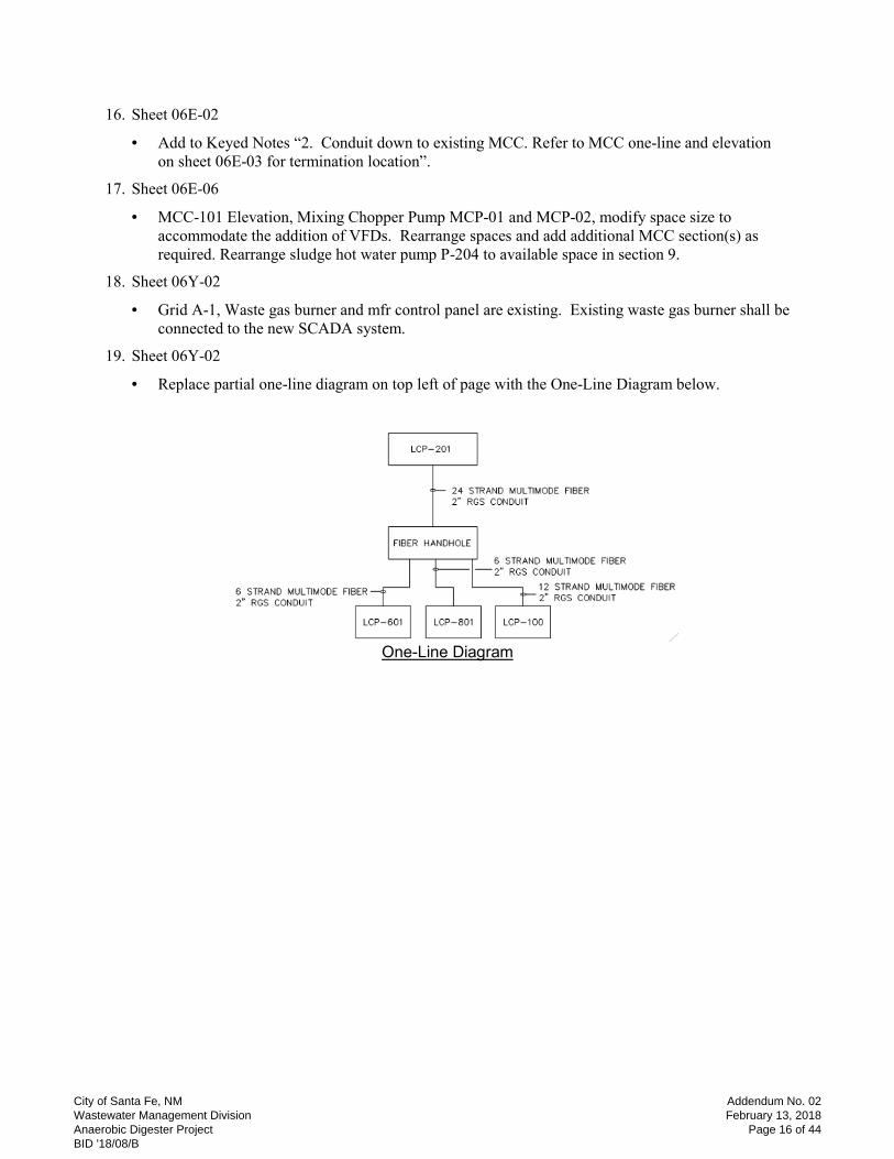
19. Sheet 06Y-02
• Replace partial one-line diagram on top left of page with the One-Line Diagram below.
One-Line Diagram
City of Santa Fe, NM Wastewater Management Division Anaerobic Digester Project BID '18/08/B
Addendum No. 02February 13, 2018
Page 16 of 44
City of Santa Fe, NM Wastewater Management Division Anaerobic Digester Project BID '18/08/B
Addendum No. 02February 13, 2018
Page 17 of 44

City of Santa Fe, NM Wastewater Management Division Anaerobic Digester Project BID '18/08/B
Addendum No. 02February 13, 2018
Page 18 of 44
City of Santa Fe, NM Wastewater Management Division Anaerobic Digester Project BID '18/08/B
Addendum No. 02February 13, 2018
Page 19 of 44
City of Santa Fe, NM Wastewater Management Division Anaerobic Digester Project BID '18/08/B
Addendum No. 02February 13, 2018
Page 20 of 44

City of Santa Fe, NM Wastewater Management Division Anaerobic Digester Project BID '18/08/B
Addendum No. 02February 13, 2018
Page 21 of 44

City of Santa Fe, NM Wastewater Management Division Anaerobic Digester Project BID '18/08/B
Addendum No. 02February 13, 2018
Page 22 of 44

City of Santa Fe, NM Wastewater Management Division Anaerobic Digester Project BID '18/08/B
Addendum No. 02February 13, 2018
Page 23 of 44
City of Santa Fe, NM Wastewater Management Division Anaerobic Digester Project BID '18/08/B
Addendum No. 02February 13, 2018
Page 24 of 44
City of Santa Fe, NM Wastewater Management Division Anaerobic Digester Project BID '18/08/B
Addendum No. 02February 13, 2018
Page 25 of 44
City of Santa Fe, NM Wastewater Management Division Anaerobic Digester Project BID '18/08/B
Addendum No. 02February 13, 2018
Page 26 of 44

City of Santa Fe, NM Wastewater Management Division Anaerobic Digester Project BID '18/08/B
Addendum No. 02February 13, 2018
Page 27 of 44

City of Santa Fe, NM Wastewater Management Division Anaerobic Digester Project BID '18/08/B
Addendum No. 02February 13, 2018
Page 28 of 44
City of Santa Fe, NM Wastewater Management Division Anaerobic Digester Project BID '18/08/B
Addendum No. 02February 13, 2018
Page 29 of 44

City of Santa Fe, NM Wastewater Management Division Anaerobic Digester Project BID '18/08/B
Addendum No. 02February 13, 2018
Page 30 of 44

City of Santa Fe, NM Wastewater Management Division Anaerobic Digester Project BID '18/08/B
Addendum No. 02February 13, 2018
Page 31 of 44
City of Santa Fe, NM Wastewater Management Division Anaerobic Digester Project BID '18/08/B
Addendum No. 02February 13, 2018
Page 32 of 44

City of Santa Fe, NM Wastewater Management Division Anaerobic Digester Project BID '18/08/B
Addendum No. 02February 13, 2018
Page 33 of 44

City of Santa Fe, NM Wastewater Management Division Anaerobic Digester Project BID '18/08/B
Addendum No. 02February 13, 2018
Page 34 of 44
Addendum No. 2
City of Santa Fe Anaerobic Digester
December 2017 - Rev Issued for Construction
PACKAGED DIGESTER GAS TREATMENT SYSTEM 46 73 36 - 1
SECTION 46 73 36 1
PACKAGED DIGESTER GAS TREATMENT SYSTEM 2
PART 1 - GENERAL 3
1.1 SUMMARY 4
A. Section Includes: 5
1. Furnishing a skid mounted digester gas moisture removal, treatment, and compression 6
system. 7
B. Related Sections include but are not necessarily limited to: 8
1. Division 00 - Procurement and Contracting Requirements. 9
2. Division 01 - General Requirements. 10
C. Completely coordinate with work of other trades. 11
1.2 QUALITY ASSURANCE 12
A. Manufacturer Qualifications: 13
1. The Gas Handling and Treatment System shall be furnished by a single manufacturer or 14
supplier to be responsible for proper selection of components, their manufacture and 15
assembly and the proper functioning of the complete units. 16
2. Each component of the Gas Handling and Treatment System shall be the standard product 17
of a manufacturer regularly engaged in the production of this type of equipment. The 18
component to be furnished shall be of proven quality and correct application to this work 19
and shall be designed, constructed and installed in accordance with best practices and 20
methods. Each component and ancillary equipment items furnished under this Section shall 21
be new and unused, and the product of a manufacturer having a successful record of 22
manufacturing and servicing the equipment. 23
3. The Gas Handling and Treatment System shall be furnished by a Supplier that is qualified 24
and experienced in the packaging of digester gas treatment systems. The equipment 25
Supplier shall have at least 5 years of experience in the design, application, and supply of 26
packaged systems and shall submit a list of equipment installations in North America as 27
evidence of meeting the experience requirement. 28
B. Referenced Standards: 29
1. ANSI: 30
a. B16.5, Pipe Flanges and Flanged Fittings 31
2. International Building Code 32
1.3 SUBMITTALS 33
A. Shop Drawings: 34
1. See Section 01 33 00 for requirements for the mechanics and administration of the submittal 35
process. 36
2. Plans and elevations showing location and dimension of components. 37
3. Details of connections, design elements, and relation to adjacent items. 38
B. Product Data: 39
1. Acknowledgement that products submitted meet requirements of standards referenced. 40
2. Manufacturer's installation instructions. 41
3. Fabrication and/or layout drawings showing location of anchor bolts, location, size and 42
connection method including specification designation for all external piping connections, 43
dimensions and weights for all Gas Handling and Treatment System components. 44
4. Descriptive literature, manufacturer catalog cut sheets, specifications, materials of 45
construction for all Gas Handling and Treatment System components. 46
City of Santa Fe, NM Wastewater Management Division Anaerobic Digester Project BID '18/08/B
Addendum No. 02February 13, 2018
Page 35 of 44
Addendum No. 2
City of Santa Fe Anaerobic Digester
December 2017 - Rev Issued for Construction
PACKAGED DIGESTER GAS TREATMENT SYSTEM 46 73 36 - 2
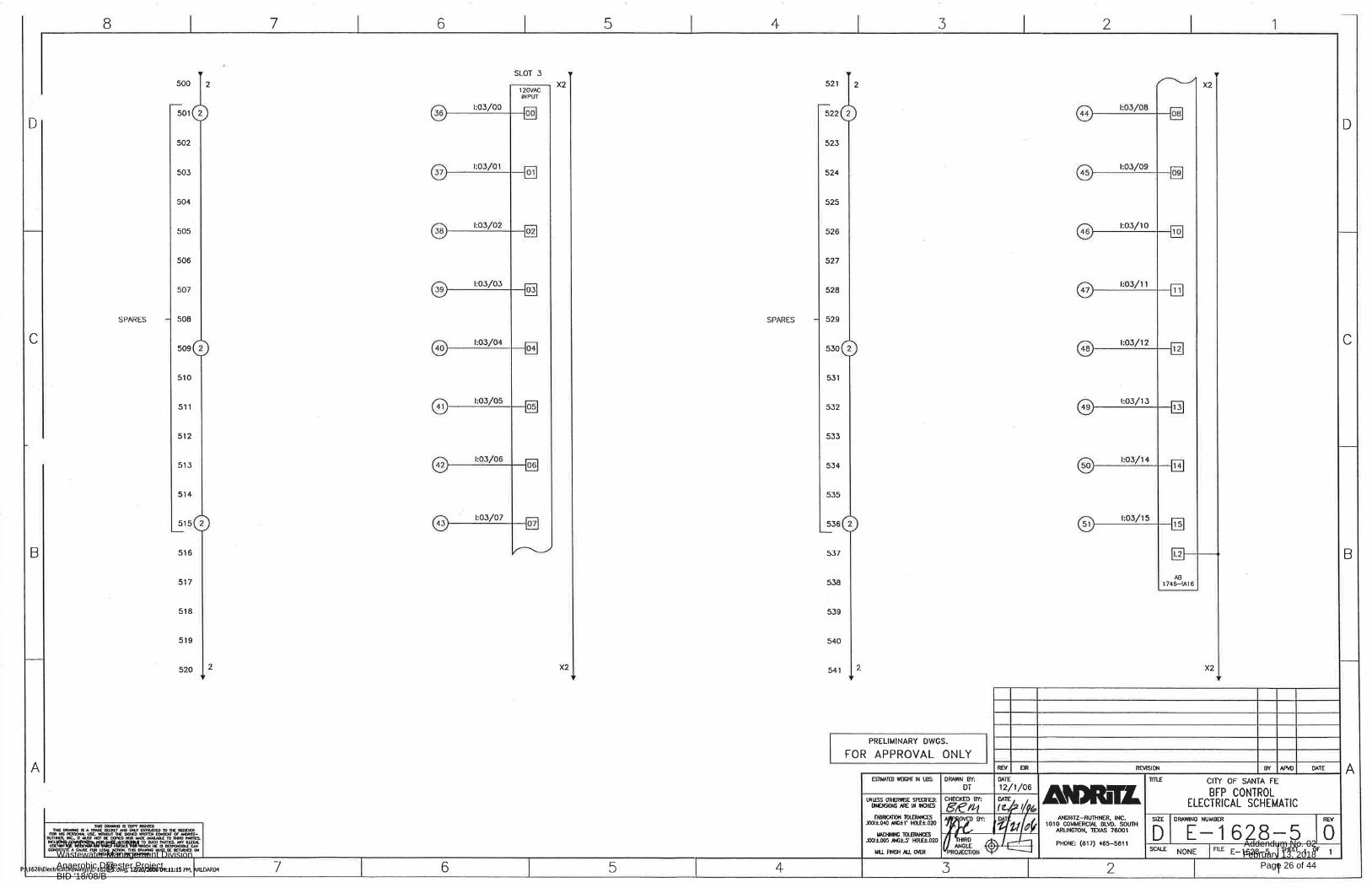
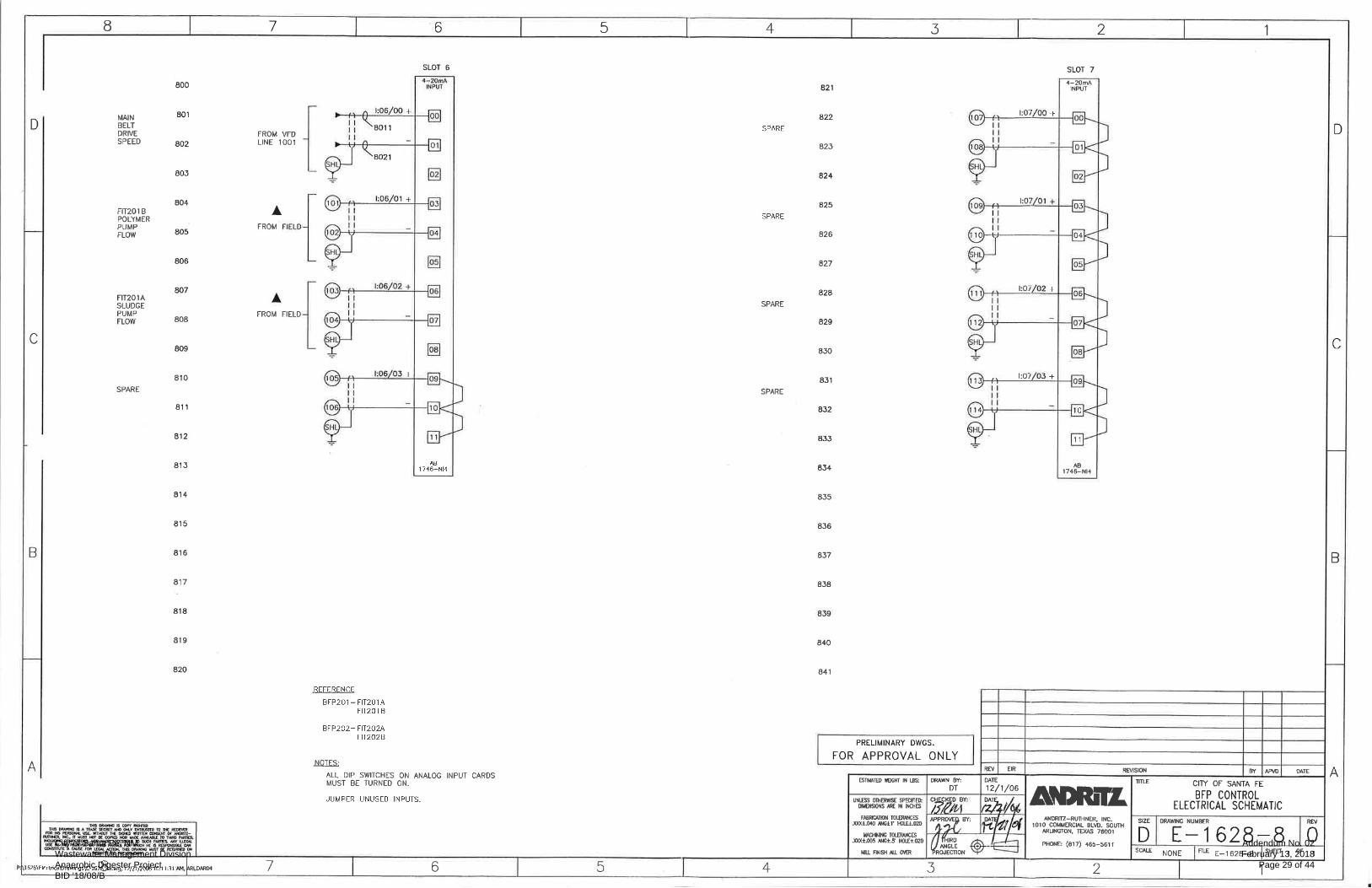
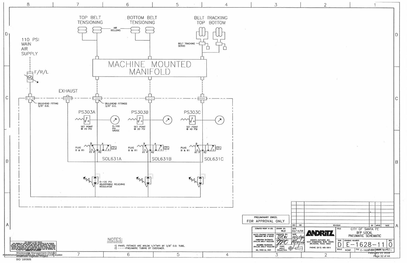
5. Detailed schematic and wiring diagrams showing piping and wiring connections with sizes 1
required and location for the controls of all Gas Handling and Treatment System 2
components. 3
6. Seismic calculations for all skids, tanks, and equipment. 4
7. Manufacturer’s installation, operation and maintenance manuals, bulletins, and spare parts 5
lists for all Gas Handling and Treatment System components. 6
8. Equipment list identifying all equipment, instruments, and ancillary components to be 7
supplied by the Gas Handling and Treatment System Supplier. For equipment, instruments, 8
and ancillary components that will be shipped and pre-installed on a skid package, the 9
equipment list shall identify the skid package that they will be pre-installed upon. 10
Equipment, instruments, and ancillary components that are to be shipped loose, shall be 11
identified as such. 12
9. Wiring diagram showing all electrical external connections. 13
10. PLC I/O list, and program listing. 14
11. Design Data 15
a. Blower: Rotational speed at full load, frequency, voltage, number of phases, full load 16
current, enclosure designation, NEMA code design letter, efficiency, horsepower rating, 17
temperature rise, bearing life rating and method of lubrication. 18
b. Hydrogen Sulfide Scrubber: Pressure drop calculations when the medium is 90 percent 19
spent, minimum and maximum allowable flows, media usage rate based on average 20
H2S concentration 21
c. Heat Exchanger: Inlet and outlet temperatures, flow rates, pressure drops, heat 22
rejection, and heat transfer coefficients for both sections of the exchanger, and weight 23
and volume of moisture condensed from gas stream. 24
d. Refrigeration System: Design heat rejection, flow rates, pressure drops, motor 25
horsepower, assumed ambient temperature, unit efficiency. 26
e. Siloxane Scrubber: Pressure drop calculations when the medium is 90 percent spent, 27
minimum and maximum allowable flows, media usage rate based on average VOC and 28
Siloxane concentrations. 29
f. Particulate Filter: Pressure drop when the filter is 90 percent utilized, removal 30
efficiency 31
12. Certifications. 32
13. Test reports. 33
a. A test report documenting the performance of all components included in the Gas 34
Handling System. Documentation shall be based on shop testing of Gas Handling 35
System on air prior to delivery on site. Flow, pressure, and temperature performance 36
must meet design requirements and be approved by the Owner’s Representative prior to 37
acceptance. 38
14. Supplier Qualifications 39
a. Qualifications for the Gas Handling System Supplier must be submitted prior to 40
approval of the system by the Owner’s Representative. The qualifications information 41
must include at a minimum, reference project with contact information, firm financial 42
statements or other proof of firm financial condition, number of personnel available for 43
service and start up, and experience with digester gas or landfill gas applications. 44
C. Contract Closeout Information: 45
1. Operation and Maintenance Data: 46
a. See Section 01 33 04 for requirements for the mechanics, administration, and the 47
content of Operation and Maintenance Manual submittals. 48
1.4 WARRANTY 49
A. The Gas Handling and Treatment System shall be provided with a one year warranty, effective 50
following start-up, from the Supplier in addition to manufacturer’s warranties for individual 51
components of the Gas Handling System. The warranty certificate shall be submitted in writing 52
and signed by an officer of the Packager’s firm, as part of the submittal package. 53
City of Santa Fe, NM Wastewater Management Division Anaerobic Digester Project BID '18/08/B
Addendum No. 02February 13, 2018
Page 36 of 44

Addendum No. 2
City of Santa Fe Anaerobic Digester
December 2017 - Rev Issued for Construction
PACKAGED DIGESTER GAS TREATMENT SYSTEM 46 73 36 - 3
PART 2 - PRODUCTS 1
2.1 MANUFACTURERS 2
A. Subject to compliance with the Contract Documents, only the following manufacturers are 3
acceptable: 4
1. Unison Solutions 5
2. Engineer approved equal. 6
B. Submit request for substitution in accordance with Section 01 25 13. 7
2.2 SYSTEM REQUIREMENTS 8
A. Furnish all labor, materials, equipment and incidentals to manufacture and supply a skid 9
mounted digester gas moisture removal, treatment, and compression system (the Gas Handling 10
and Treatment System) for the Paseo Real Wastewater Treatment Plant in Santa Fe, New 11
Mexico. The Gas Handling and Treatment System shall include at a minimum, onehydrogen 12
sulfide scrubber, one gas blower, a gas cooling heat exchanger with integral moisture removal, 13
glycol refrigeration system, prefabricated enclosure for compression and moisture removal skid, 14
two siloxane scrubber treatment vessels, one particulate filter, valves, piping and controls as 15
specified herein. The specification indicates there are four skids for the system for the purposes 16
of defining the elements needed for the system. The supplier shall determine the best means for 17
packaging the system in terms of the number of actual skids that are shipped to the project site. 18
19
Item Equipment No.
H2S Scrubber System HS-1 H2S System Air Compressor AC-1 Digester Gas Cooling Chiller Unit Pump CGP-1 Digester Gas Cooling Chiller Unit GCU-1 Digester Gas Cooling Heat Exchanger/Moisture Separator
HX-1
Digester Gas Pressure Booster PB-1 Siloxane Scrubber System SS-1 Particulate Filter PF-1
2.3 PERFORMANCE AND DESIGN REQUIREMENTS 20
A. Design Requirements and Operating Conditions 21
1. Equipment shall be specifically designed and selected for continuous duty for moisture 22
removal, treatment, and compression of digester gas. The approximate composition and 23
characteristics of the digester gas at the inlet to the Gas Handling and Treatment System is 24
indicated as follows: 25
26
Item Value
Specific Gravity 0.7 to 0.9 Nitrogen 0 to 3 percent Methane 55 to 65 percent Carbon Dioxide 35 to 43 percent Hydrogen Sulfide (average) 1000 ppm Hydrogen Sulfide (maximum) 2000 ppm Siloxanes 8 mg/m
3 (total as Si)
VOC 1 ppmv total Temperature 80 to 105 degrees Fahrenheit Moisture Saturated Pressure 6 to 10 inches of water column
27
2. Supports for all vessels and equipment shall be designed to meet the seismic requirements 28
for Santa Fe, New Mexico. 29
3. The system shall have a capacity of 120 scfm. 30
B. Performance Requirements 31
City of Santa Fe, NM Wastewater Management Division Anaerobic Digester Project BID '18/08/B
Addendum No. 02February 13, 2018
Page 37 of 44

Addendum No. 2
City of Santa Fe Anaerobic Digester
December 2017 - Rev Issued for Construction
PACKAGED DIGESTER GAS TREATMENT SYSTEM 46 73 36 - 4
1. The Gas Handling and Treatment System shall treat and compress the gas to the following 1
levels as measured at the discharge of the System: 2
Item Value
Outlet Pressure (from the Gas Handling and Treatment System)
3.0 psig (minimum)
Hydrogen Sulfide 50 ppm (maximum) Siloxane 0.1 mg/m
3 as Si per siloxane species D4, D5, and D6,
25% average reduction in L2, and 50% average reduction in L3.
Relative Humidity 50% Particulate Removal 99 percent reduction of all particles 3 microns and larger Discharge Temperature (maximum)
80 degrees Fahrenheit
3
C. Project / Site Requirements 4
1. All components of the Gas Handling and Treatment System will be located outdoors in an 5
NEC classified Class 1, Division 1 area. 6
2.4 COMPONENTS 7
A. General 8
1. All components of the Gas Handling and Treatment System shall have firmly attached to 9
each component a stainless steel nameplate. The nameplate shall have on it, as a minimum, 10
the name of the manufacturer, the model number and the serial number. Drive motor 11
nameplates shall have on them the name of the manufacturer, model number, serial number, 12
volts, full load current, rated horsepower, service factor, full load rotational speed and 13
temperature rating. 14
B. Hydrogen Sulfide Treatment Skid 15
1. The hydrogen sulfide treatment skid shall include one hydrogen sulfide scrubber vessel, air 16
compressor, support frame, and interconnecting piping. The hydrogen sulfide skid shall 17
connect to the digester gas system through a single 6-inch flanged inlet and a single 6-inch 18
flanged outlet connection. 19
2. The hydrogen sulfide treatment skid shall be sized to limit pressure drop through the vessel 20
and piping to no more than 6 inches of water column. 21
3. All equipment and instruments located within 5 feet of the digester gas process lines and the 22
digester gas handling equipment shall be Listed and Labeled for use in NEC Class 1 23
Division 1 area. 24
4. Hydrogen Sulfide Scrubber Vessel 25
a. The hydrogen sulfide scrubber vessel shall be designed for in situ air regeneration 26
without requiring the removal of the hydrogen sulfide scrubber media. 27
b. Hydrogen sulfide scrubber vessel shall be made of welded stainless steel according to 28
ASME standards. The vessel shall be provided an opening large enough to permit 29
inspection of the vessel and medium exchange. 30
c. The hydrogen sulfide scrubber vessel shall be provided with a 1½-inch drain 31
connection originating from the lowest point of the scrubber vessel. The 1½-inch drain 32
shall be provided with a stainless steel ball valve. 33
d. The hydrogen sulfide scrubber vessel shall be provided with a condensate collection 34
pipe with a timer controlled electronically actuated drip trap. Electronics for the timer 35
and actuator shall be explosion proof and Listed and Labeled for operation in a Class 1 36
Division 1 classified area. The timer and drip trap solenoid shall be rated for 120VAC, 37
single phase, power supply. 38
5. Air Compressor: An air compressor shall be provided to supply regeneration air to the 39
hydrogen sulfide scrubber. Air compressor shall be use 110 V single phase electrical 40
power. 41
6. Hydrogen Sulfide Treatment Skid Piping. 42
City of Santa Fe, NM Wastewater Management Division Anaerobic Digester Project BID '18/08/B
Addendum No. 02February 13, 2018
Page 38 of 44
Addendum No. 2
City of Santa Fe Anaerobic Digester
December 2017 - Rev Issued for Construction
PACKAGED DIGESTER GAS TREATMENT SYSTEM 46 73 36 - 5
a. All equipment provided on the hydrogen sulfide treatment skid shall be pre-piped and 1
connected from the manufacturer. Piping and valving shall be as shown on drawings. 2
b. Digester gas piping shall be schedule 10, 304 stainless steel. 3
c. The digester gas piping shall include shall include digester gas sampling taps with 4
shutoff valve upstream and downstream of the hydrogen sulfide scrubber system. 5
d. Air piping shall be pre-piped by the Supplier of the Gas Handling and Treatment 6
System and shall connect the air compressor to the digester gas piping upstream of the 7
hydrogen sulfide scrubber vessels. Air piping shall be stainless steel. 8
7. Accessories 9
a. Provide a magnahelic type differential pressure gage on each vessel for the monitoring 10
vessel gas pressure drop. The differential pressure gage shall be located to be easily 11
viewed from ground level and shall be calibrated for differential pressure between 0 to 12
10 inches of water column. 13
b. Provide stainless steel ANSI flanged valves on the inlet and outlet of each vessel. 14
c. General Contractor shall provide two 110 V, single phase, electrical outlets on skid to 15
power miscellaneous equipment. Outlets shall be rated for outdoor use with outdoor 16
cover in compliance with National Electrical Code. 17
8. Iron Sponge Media 18
a. The vessel shall be provided fully charged with hydrated ferric oxide (Iron Sponge) 19
media. 20
b. The hydrated ferric oxide media shall consist of wood chips impregnated with fifteen 21
pounds of hydrated ferric oxide per cubic foot. Each scrubber shall be provided with 22
enough Iron Sponge media to provide a 6 month bed life, based on average H2S 23
concentration. 24
c. The General Contractor shall install the initial charge of media for the vessel. 25
C. Digester Gas Moisture Removal and Compression Skid 26
1. The digester gas moisture removal and compression skid shall include one digester gas 27
booster blower, a digester gas cooling heat exchanger with integral moisture separator, 28
temperature controlled enclosure, all necessary drip traps, required instrumentation, a flow 29
control valve, and interconnecting piping. Refer to the drawings for system configuration. 30
2. Interconnecting piping shall be pre-piped by the Supplier. 31
3. The digester gas moisture removal and compression skid shall connect to the digester gas 32
system through a single 6-inch inlet flanged connection and a single 4-inch outlet flanged 33
connection. 34
4. Skid shall have 150-pound ANSI B16.5 flanges at inlet and outlet of skid for direct 35
connections to gas piping. 36
5. All equipment and instruments located within 5 feet of the digester gas process lines and the 37
digester gas handling equipment shall be Listed and Labeled for use in NEC Class 1 38
Division 1 area. 39
6. Digester Gas Cooling Heat Exchanger 40
a. The heat exchanger shall be a dual core, digester gas to digester gas/digester gas to 41
chilled glycol heat exchanger sized such that it cools the saturated digester gas from the 42
inlet temperature plus the heat of compression down to 40 degrees Fahrenheit and 43
reheats the gas to 80 degrees Fahrenheit 44
b. The heat exchanger shall be sized such that moisture can flow freely from the heat 45
exchanger without blocking or causing excessive pressure drop through the unit. 46
c. Heat exchanger components in contact with the digester gas shall be 304 stainless steel. 47
d. The heat exchanger shall be designed to include an integral moisture separator. 48
e. Level switch on heat exchanger housing to warn of drain failure. 49
f. RTD mounted on heat exchanger housing to verify the coldest temperature the gas 50
reaches. 51
g. Bottom drain with strainer, float drain, manual bypass, and piping. 52
7. Digester Gas Pressure Booster Blower. 53
a. The digester gas blower shall be a heavy duty blower designed for continuous service 54
of compressing digester gas as specified herein. 55
City of Santa Fe, NM Wastewater Management Division Anaerobic Digester Project BID '18/08/B
Addendum No. 02February 13, 2018
Page 39 of 44
Addendum No. 2
City of Santa Fe Anaerobic Digester
December 2017 - Rev Issued for Construction
PACKAGED DIGESTER GAS TREATMENT SYSTEM 46 73 36 - 6
b. The booster blower shall be sized to boost 120 cfm of digester gas from atmospheric 1
pressure to an acceptable pressure that will achieve 2 psig at the inlet of the engine fuel 2
trains. 3
c. Digester gas blowers shall include miscellaneous accessories including gauges, 4
switches, valves, discharge silencers, piping, controls, and wiring necessary for a 5
complete installation. 6
d. The casing material shall be for digester gas service. 7
e. The shaft shall be sealed with a mechanical seal and shall not require oil lubrication. 8
f. Digester gas booster blowers shall not exceed 80 dbA at a three foot radius from the 9
blower. Noise enclosures and inlet silencers may be provided as a mitigation method to 10
achieve the 80 dbA requirement. 11
g. Digester gas booster blowers shall be VFD driven. Variable frequency drive shall be 12
furnished and installed in by the General Contractor. The motor shall be inverter duty 13
rated. 14
8. Booster Blower Inlet Filters 15
a. The inlet filters shall be constructed with a 304 stainless steel housing. The filter media 16
shall provide 99 percent removal efficiency of droplets 3 microns and larger. 17
b. The coalescing package shall be provided with a drain connection to a condensate drain 18
pump. Pump will be controlled by high and low level switches. Electronics for the 19
pump and switches shall be explosion proof and Listed and Labeled for operation in a 20
Class 1 Division 1 classified area. Condensate pump shall be rated for 120VAC, single 21
phase power supply. 22
9. Interconnecting Piping 23
a. All equipment provided on the digester gas moisture removal and compression skid 24
shall be pre-piped and connected from the manufacturer. 25
b. Digester gas piping shall be schedule 10, 304 stainless steel.. 26
c. The digester gas piping shall incorporate a recirculation bypass. A thermal mass flow 27
meter shall be included to provide a signal that will allow for actuation of a motorized 28
valve and prevent surge conditions in the booster blowers. Motorized valve shall be 29
460 VAC, 3 phase. 30
d. Interconnecting piping shall include digester gas pressure and temperature indication 31
upstream and downstream of the digester gas cooling heat exchanger. 32
e. Pressure and Temperature transmitters shall be provided between the Digester Gas 33
Moisture Separator and the recirculation bypass. 34
f. Isolation valves shall be provided to isolate the digester gas cooling heat exchanger, the 35
digester gas moisture separator, and both digester gas pressure booster blowers. 36
10. Temperature Controlled Enclosure 37
a. Supplier shall provide a temperature controlled enclosure for the moisture 38
removal/compression skid. 39
b. All electrical inside the enclosure is rated Class I Division 1. 40
c. Enclosure shall be equipped with a steel exterior and ½” plywood interior construction 41
over steel studs. Coordinate with Owner on exterior paint color. 42
d. The interior shall have insulated walls and ceiling. 43
e. The enclosure shall be equipped with two explosion proof incandescent light fixtures. 44
f. A thermostatically controlled heater shall be installed in the enclosure to prevent 45
freezing. 46
g. Combustible gas detection shall be installed for gas detection and warning. 47
h. Ventilation fan and intake louver shall be installed to prevent over-heating inside 48
enclosure. 49
i. Access to the enclosure shall be through double steel entry doors. Coordinate with 50
owner on door hardware. 51
D. Chiller System Skid 52
1. The chiller system skid shall include a refrigerant dryer/chiller and glycol pump to reduce 53
the dew point of the digester gas and allow the removal of siloxanes. 54
City of Santa Fe, NM Wastewater Management Division Anaerobic Digester Project BID '18/08/B
Addendum No. 02February 13, 2018
Page 40 of 44

Addendum No. 2
City of Santa Fe Anaerobic Digester
December 2017 - Rev Issued for Construction
PACKAGED DIGESTER GAS TREATMENT SYSTEM 46 73 36 - 7
2. The Gas Handling and Treatment Supplier must coordinate the digester gas cooling heat 1
exchanger and the refrigerant/dryer system to ensure that the equipment will meet the 2
requirements for cooling the digester gas as described in Paragraph 2.03 E. 3
3. For sizing the coolant pump, the Gas Handling and Treatment Supplier shall assume 40 ft of 4
piping from the coolant supply and return between the digester gas cooling heat exchanger 5
and the refrigerant/dryer system. Supplier shall account for headloss from any valves needed 6
as part of the system. 7
4. The chiller package shall be provided with its own control system to control the chiller 8
motor and chiller pump. Temperature indication of the glycol supply and return 9
temperature shall be provided. The control panel for the chiller package shall be installed 10
on the skid. 11
E. Siloxane Scrubber Skid 12
1. The siloxane scrubber skid shall include two siloxane scrubber vessels, support frame, and 13
interconnecting piping. 14
2. Siloxane Scrubber Vessels 15
a. The siloxane scrubber vessels shall be a custom fabricated, high-performance device 16
that is designed for maximum removal at low pressure drops. 17
b. Siloxane scrubber vessels shall have 150-pound ANSI B16.5 flanges for direct 18
connections to gas piping. Siloxane scrubber vessels shall be fabricated from 304 SS. 19
c. Siloxane scrubber vessels shall be tapped and equipped with a 1-inch threaded and 20
valved drain plug, three 3/4-inch or 1-inch threaded gage couplings and a ½-inch 21
threaded and valved nitrogen purge connection. Two of the three couplings shall serve 22
the differential pressure gage and shall be located upstream and downstream of the 23
activated carbon. The other coupling shall be available for future connections 24
downstream of the activated carbon. The nitrogen purge connection shall be located on 25
the inlet piping of the tank, downstream of the isolation valve. 26
d. The nitrogen purge connections shall be equipped with self-closing, quick-connect 27
couplings. The socket shall be provided with a Male NPT connection. The plug shall 28
be provided with a hose clamp end connection. 29
e. Siloxane scrubber vessels shall be on a prefabricated skid and shall have hinged 12 x 16 30
inch elliptical hand holes and access covers with easy-open swing bolts, toggle bolts, or 31
similar latches. Gasket materials shall be Buna-N. 32
f. Siloxane scrubber vessels shall be equipped with retention screens. Screens shall be 33
removable to accommodate vessel servicing. 34
3. Support Frame 35
a. The treatment vessel shall be supported on a stainless steel,galvanized steel, or powder 36
coated carbon frame designed by a registered Professional Engineer in the State of New 37
Mexico. 38
4. Interconnecting Piping 39
a. All equipment provided on the siloxane scrubber skid shall be pre-piped and connected 40
from the manufacturer and as shown on the drawings. 41
b. Digester gas piping shall be schedule 10, 304 SS. 42
5. Accessories 43
a. Provide a magnahelic type differential pressure gage for the monitoring vessel gas 44
pressure drop. The differential pressure gage shall be located to be easily viewed from 45
ground level and shall be calibrated for differential pressure between 0 to 5 psig. 46
b. Provide ANSI flanged valves on the inlet and outlet of the vessel. 47
c. Provide two 110 V electrical outlets on skid to power miscellaneous equipment. . 48
Outlets shall be rated for outdoor use with outdoor cover in compliance with National 49
Electrical Code 50
6. Siloxane Scrubber Media 51
a. The vessel supplier shall provide the initial charge of virgin activated carbon, graphite 52
molecular sieve, and/or silica molecular sieve for each vessel. 53
City of Santa Fe, NM Wastewater Management Division Anaerobic Digester Project BID '18/08/B
Addendum No. 02February 13, 2018
Page 41 of 44

Addendum No. 2
City of Santa Fe Anaerobic Digester
December 2017 - Rev Issued for Construction
PACKAGED DIGESTER GAS TREATMENT SYSTEM 46 73 36 - 8
b. Activated carbon shall have a hardness of greater than 98 percent, shall have a moisture 1
content less than 3 percent, shall have a carbon tetrachloride (CCl4) adsorption greater 2
than 75 percent, and shall have a total ash level less than 10 percent. Nominal particle 3
diameter shall be 2 mm. 4
c. The scrubbers shall be provided with enough siloxane scrubber media to provide a 6 5
month bed life for each vessel. 6
d. Siloxane scrubber media shall be easily removed and refilled into the siloxane scrubber 7
vessels. Design of the siloxane scrubber skid should be such that all tools required for 8
removal of media and refilling media can be easily operated without causing the 9
disassembly of any part of the skid, other than hatches and opening on the scrubber 10
vessels. 11
e. All specialty tools and apparatus required for the removal and refilling of siloxane 12
scrubber media shall be provided. 13
f. The General Contractor shall install the media in the siloxane vessels. 14
F. Particulate Filters 15
1. One particulate filter shall be provided to remove any remaining particulates immediately 16
prior to sending the digester gas to the engine fuel train. 17
2. Particulate filter shall remove 99 percent of particles in excess of 3 microns. 18
G. Drive Motors 19
1. Drive motors shall be NEC Class 1, Group D, Division 1 explosion-proof, TEXP motors, 20
such as Toshiba, US Motors. Motor shall be inverter duty rated for variable-frequency 21
drive. 22
2. Drive motor horsepower rating shall be such that the motor will not be overloaded over the 23
full range of operating conditions of the gas blower, not including the 1.15 Hp service factor 24
as required herein. 25
3. The motor shall conform as follows: 26
a. Maximum synchronous speed - 3600 rpm 27
b. Slip 3 percent at full load 28
c. Voltage 460 Volts 29
d. Phases 3 30
e. Frequency 60 Hz 31
f. Mounting horizontally on blower skid or mounting frame 32
g. Bearings ball type, anti friction, ABMA L 10 life 100,000 hours 33
h. Bearing lubrication manufacturer's standard 34
i. Service factor 1.15 35
H. Power and Control 36
1. General 37
a. Supplier shall provide all motors and instruments as indicated herein. 38
b. The supplier shall provide a fully functional control system to operate the Gas Handling 39
and Treatment System. The control system shall provide signals to the engine system to 40
allow it to modulate based on digester gas production. 41
c. All power and control equipment shall be wired on skids to terminals for the General 42
Contractor to connect to remote locations. 43
2. Electrical starters and variable frequency drive shall be provided by the General Contractor. 44
3. Pressure and Temperature gauges shall be supplied on all inlets and outlets of each skid. 45
I. Surface Preparation and Field Painting 46
1. All non-stainless steel surfaces shall be primed and painted in the shop as a part of the work 47
under this Section. Powder coated steel is acceptable for support structures. 48
City of Santa Fe, NM Wastewater Management Division Anaerobic Digester Project BID '18/08/B
Addendum No. 02February 13, 2018
Page 42 of 44

Addendum No. 2
City of Santa Fe Anaerobic Digester
December 2017 - Rev Issued for Construction
PACKAGED DIGESTER GAS TREATMENT SYSTEM 46 73 36 - 9
PART 3 - EXECUTION 1
3.1 INSTALLATION 2
A. Supply of anchor bolts, temporary lift equipment, power, water, labor and all other incidentals 3
required for proper installation of the equipment will be provided by the General Contractor. 4
B. Installation shall be in strict accordance with the Gas Handling and Treatment System Supplier’s 5
recommendations and instructions and the best practices of the trade. Anchor bolts shall be set 6
in accordance with the manufacturer's installation drawings or template. Installation shall 7
include connections required for cooling water, power and controls. Installation shall be 8
completed by the General Contractor. General Contractor shall fill vessels with media. 9
3.2 FIELD QUALITY CONTROL 10
A. Functional Test: 11
1. Prior to placing the equipment into operation all equipment described in this Section shall 12
be inspected, in the presence of the Owner’s Representative and the Gas Handling and 13
Treatment System Supplier's representative, for proper connection, proper alignment, quiet 14
operation and satisfactory performance by means of a functional test. The Gas Handling 15
and Treatment System shall be operated under the full range of conditions that can be 16
expected in this installation, including a simulation loss of cooling supply. During the 17
functional test the mechanical elements shall be observed for excessive vibration and noise 18
and for overheating. Furnish and install temporary electric metering equipment to allow 19
observance of the power draw by the unit under the full range of operating conditions. 20
2. Upon completion of the functional tests, certify in writing that the installation is acceptable 21
and will not invalidate any warranty provided for the equipment. 22
B. Performance Test and Media Life Test: 23
1. A Performance Test will be conducted as part of the commissioning process. Immediately 24
following commissioning, raw gas and treated gas samples will be taken by the Supplier of 25
five consecutive days and sent to a lab for analysis. 26
2. The Owner may independently sample and analyze the gas. If the Owner’s sample analysis 27
and the Gas Handling and Treatment System Suppliers analysis differ, a subsequent sample 28
shall be taken and sent to an independent laboratory for verification. If the subsequent 29
analysis shows that the Gas Handling and Treatment System is meeting the performance 30
specifications of this section than the Owner will pay for the subsequent sampling and gas 31
analysis. If the subsequent analysis shows that Gas Handling and Treatment System fails to 32
meet the performance requirements of this specification, then the Gas Handling and 33
Treatment System Supplier shall pay for the subsequent sampling and gas analysis. 34
3. Failure to meet the performance requirements listed in this Section shall be cause for 35
replacement or repair at the Gas Handling and Treatment System at Supplier’s expense. 36
4. . A Media Life test shall be conducted two months following commissioning of the Gas 37
Handling and Treatment System and again four months after commissioning of the Gas 38
Handling and Treatment System to determine the level of digester gas treatment. 39
5. The Media Life Test shall be conducted using the original iron sponge media and siloxane 40
scrubber media supplied as part of the original contract. Test procedures shall be provided 41
by the Gas Handling and Treatment System Supplier and approved by the Owner’s 42
Representative. Chemical analysis shall be provided by the Gas Handling and Treatment 43
System Supplier. 44
6. The Gas Handling and Treatment System Supplier may request monthly samples and gas 45
analysis of the digester gas prior to treatment to verify that the digester gas is in compliance 46
with the Design Requirements and Operating Conditions of this Section. All equipment and 47
gas analyses required for the monthly testing shall be paid by the Gas Handling and 48
Treatment System Supplier. If requested by the Supplier, The Owner can perform the 49
sampling for Supplier requested analysis. 50
C. Service Support 51
City of Santa Fe, NM Wastewater Management Division Anaerobic Digester Project BID '18/08/B
Addendum No. 02February 13, 2018
Page 43 of 44
Addendum No. 2
City of Santa Fe Anaerobic Digester
December 2017 - Rev Issued for Construction
PACKAGED DIGESTER GAS TREATMENT SYSTEM 46 73 36 - 10
1. The Supplier of the Gas Handling and Treatment System shall provide a service proposal 1
for 5 years that supports the system. The service proposal shall include gas testing, labor, 2
equipment, disposal, and replacement of the siloxane removal media and hydrogen sulfide 3
scrubber media to allow for consistent operation of the hydrogen sulfide and siloxane 4
removal systems. The services proposal shall assume that H2S and Siloxane media will be 5
replaced every six months. In addition, the proposal shall include a unit cost for additional 6
H2S or Siloxane media replacements. A monthly report shall be provided by the Supplier 7
based on the gas samples collected. The monthly report shall summarize test results and 8
recommend any operation changes. All costs associated with this service proposal shall be 9
included as a bid alternate. 10
3.3 SYSTEMS STARTUP 11
A. Field Startup and Training 12
1. The Supplier of the Gas Handling and Treatment System shall provide three days of startup 13
training services for this system. Training shall include how to take gas samples and 14
preparation on chain of custody for sample taking. 15
END OF SECTION 17
City of Santa Fe, NM Wastewater Management Division Anaerobic Digester Project BID '18/08/B
Addendum No. 02February 13, 2018
Page 44 of 44