for closed hydronic heating & chilled water systems acondicionado/separadore… · for closed...
TRANSCRIPT
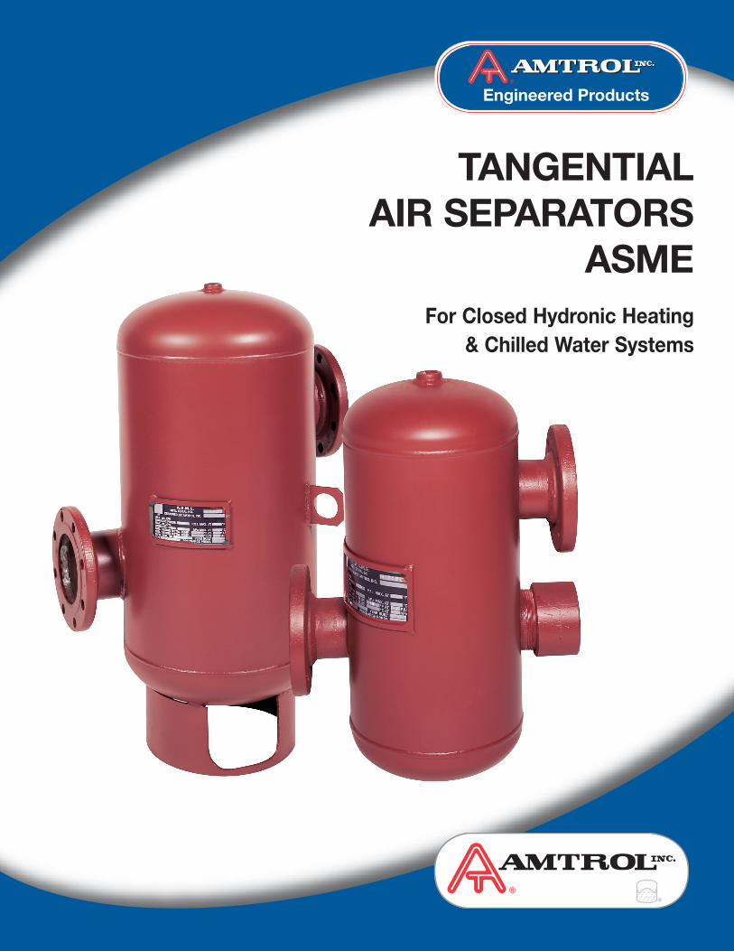
TANGENTIAL AIR SEPARATORS
ASMEFor Closed Hydronic Heating
& Chilled Water Systems
The AMTROL® Advantage .......................... 2
Advantages ................................................ 2
Benefits....................................................... 2
Features...................................................... 3
1" - 24" Air Separator Specifications .......... 3
Designing the Ideal System Flow Rate........ 4
Table of Contents
WHERE BETTER IDEAS FLOW
The AMTROL® Advantage• AMTROL – A world-leading provider of advanced water
system solutions supplies a complete line of quality-engineered, cost efficient, heating and water systems that you can count on.
• First to design and patent EXTROL®‚ expansion tanks,redefining hydronic heating and chilled water systems forever.
• ISO 9001 – 2000 Certified.
• With over 50 years experience, AMTROL sets the standardfor service, reliability, innovation, design, and manufacture ofwater system equipment.
• Fully qualified technical staff available to help ensure solid solutions for your water and heating needs.
Advantages of Air Separation andEliminationThe proper application of both the pressurization (EXTROL®‚Expansion Tanks) and air elimination (AMTROL Tangential AirSeparator) devices will solve your “System Air” problems.These key components are necessary in the design and construction of closed circulation systems.
The AMTROL line of tangential air separators are ASME vessels designed with tangential openings to create a lowvelocity vortex where entrained air is separated and removedfrom circulating water or anti-freeze in a closed system. Inaddition, these tangential air separators can be suppliedwith a stainless steel strainer to collect unwanted systemdebris.
AMTROL tangential air separators are ideally suited to help eliminate problems often associated with trapped system air such as blocked terminal units, inefficient pump operation and performance, and costly corrosion and fouling of equipment.
AMTROL’s Engineering Handbook reviews this subject in detail. Ask your localAMTROL representative for your copy.
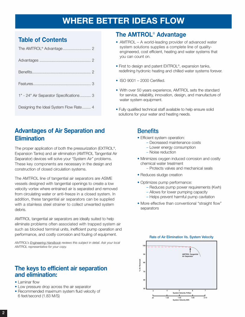
The keys to efficient air separationand elimination:• Laminar flow• Low pressure drop across the air separator• Recommended maximum system fluid velocity of
6 feet/second (1.83 M/S)
100
503
% A
ir R
emov
ed
System Velocity Ft/Sec
60
70
80
90
4 5 6 7
.91System Velocity M/S
1.22 1.52 1.83 2.13
AMTROL TangentialAir Separator
Rate of Air Elimination Vs. System Velocity
Benefits• Efficient system operation:
– Decreased maintenance costs– Lower energy consumption– Noise reduction
• Minimizes oxygen induced corrosion and costlychemical water treatment
– Protects valves and mechanical seals
• Reduces sludge creation
• Optimizes pump performance:– Reduces pump power requirements (Kwh)– Allows for lower pumping capacity– Helps prevent harmful pump cavitation
• More effective than conventional “straight flow”separators
2
TANGENTIAL AIR SEPARATORS ASME Models AS and AS-L
Materials of Construction• Steel – ANSI 150# flange construction• All steel body construction• Stainless steel strainer
Maximum Operating Conditions Maximum working pressure:125 psig (8.8 bar)
150 psig (10.5 bar)
Maximum operating temperature: 350°F/177°C
Features• Designed, constructed, and tested per ASME Section VIII,
Division 1 standards• 1 to 24 inch sizes• Tangential design with low velocity vortex action• Flanged or grooved pipe connectors• Removable, stainless steel strainer available• Blowdown connection to enable cleaning of unit and strainer • NPT vent connection
Model Model Ship Wt. Ship Wt.Number Number
Dimensionswithout with
without with A B C D E F G H I J K M* Strainer StrainerStrainer Strainer in. in. mm in. mm in. mm in. mm in. mm in. in. in. in. mm in. mm in. mm lbs. kg lbs. kg
1-AS-L — 1 41⁄2 114 12 305 4 102 4 102 7 178 3⁄4 3⁄4 15⁄16 - - - - - - 15 7 - -
2-AS-L 2-AS 2 10 254 23 584 8 203 71⁄2 191 161⁄4 413 3⁄4 3⁄4 3 - - - - 14 356 65 30 70 32
21⁄2-AS-L 21⁄2-AS 21⁄2 10 254 23 584 8 203 71⁄2 191 161⁄4 413 3⁄4 3⁄4 3 - - - - 14 356 65 30 70 32
3-AS-L 3-AS 3 10 254 23 584 8 203 71⁄2 191 17 432 3⁄4 3⁄4 3 - - - - 14 356 70 32 75 34
4-AS-L 4-AS 4 12 305 241⁄2 622 10 254 71⁄4 184 203⁄4 527 3⁄4 3⁄4 31⁄2 - - - - 161⁄2 419 75 34 80 36
5-AS-L 5-AS 5 16 406 341⁄2 876 12 305 111⁄4 286 24 610 3⁄4 3⁄4 41⁄4 123⁄4 324 45⁄8 117 211⁄2 546 145 66 180 82
6-AS-L 6-AS 6 18 457 41 1041 14 356 131⁄2 343 26 660 3⁄4 3⁄4 41⁄4 14 356 45⁄8 117 23 584 200 91 250 114
8-AS-L 8-AS 8 24 610 52 1321 18 457 17 432 32 813 3⁄4 3⁄4 53⁄4 16 406 45⁄8 117 29 737 375 170 455 207
10-AS-L 10-AS 10 30 762 591⁄2 1511 22 559 183⁄4 476 40 1016 3⁄4 3⁄4 73⁄4 24 610 45⁄8 117 35 889 650 295 770 350
12-AS-L 12-AS 12 36 914 70 1778 26 660 22 559 46 1168 3⁄4 3⁄4 73⁄4 30 762 125⁄8 321 40 1016 960 436 1150 523
14-AS-L 14-AS 14 42 1067 74 1880 30 762 22 559 52 1321 3⁄4 3⁄4 13 30 762 133⁄8 340 48 1219 1950 886 2200 1000
16-AS-L 16-AS 16 48 1219 90 2286 32 813 29 737 64 1626 3 3 15 42 1067 121⁄2 318 56 1422 3800 1727 4300 1955
18-AS-L 18-AS 18 54 1372 102 2591 36 914 331⁄4 845 64 1626 3 3 16 42 1067 123⁄8 314 62 1575 4300 1955 4900 2227
20-AS-L 20-AS 20 60 1524 102 2591 30 762 36 914 70 1778 3 3 19 45 1143 615⁄16 176 68 1727 4800 2182 5600 2545
22-AS-L 22-AS 22 60 1524 119 3023 48 1219 353⁄8 899 70 1778 3 3 18 45 1143 7 178 68 1727 5300 2409 6300 2864
24-AS-L 24-AS 24 72 1829 137 3480 43 1092 445⁄8 1133 82 2083 3 3 22 45 1143 8 203 80 2032 6900 3136 8000 3636
1"- 24" Air Separators Specifications
C
B
M
F
D
E
E
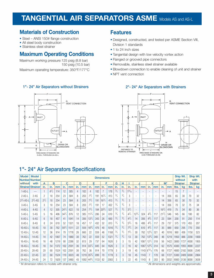
GVENT CONNECTION
HDRAW OR
BLOWDOWN
OUTLET
IINLET
A
A
K
JRING BASE STANDARD ON
5-AS THROUGH 24-AS
DISTANCE TOREMOVE STRAINER
* M dimension refers to models with strainer only. * All dimensions and weights are approximate.
2"- 24" Air Separators with Strainers1"- 24" Air Separators without Strainers
3
TANGENTIAL AIR SEPARATORS ASME Models AS and AS-L
P/N: 9017-107 MC# 2336 (08/07) ©2007 AMTROL Inc.Printed in USA
*Refer to installation manual for warranty information or visit our website at www.amtrol.com
Model Vel. 4 ft./sec. Vel. 1.2 m/sec.Vel. 6 ft./sec. Vel. 1.8 m/sec. Vel. 8 ft./sec. Vel. 2.4 m/sec.Vel.10 ft./sec. Vel.3 m/sec.
No. gpm L/sec. gpm L/sec. gpm L/sec. gpm L/sec.
1 AS-L 10 .631 15 1 20 1.26 25 1.57
2 AS-L 42 2.65 63 4 84 5 105 7
2 1/2 AS-L 60 3.78 90 6 120 7.5 150 9.5
3 AS-L 93 6 140 9 185 12 230 15
4 AS-L 160 10 240 15 320 20 400 25
5 AS-L 250 16 375 24 500 32 630 40
6 AS-L 360 23 540 34 720 45 900 57
8 AS-L 630 40 940 59 1250 79 1580 100
10 AS-L 990 62 1500 95 1980 125 2470 156
12 AS-L 1400 88 2100 133 2800 177 3500 221
14 AS-L 1680 106 2500 158 3350 211 4200 265
16 AS-L 2200 139 2800 177 3500 221 5000 316
19 AS-L 3300 208 4200 265 5200 328 7500 473
20 AS-L 4500 284 5600 353 7000 442 10000 631
24 AS-L 5500 347 7000 442 8800 555 12500 789
Maximum Flow Rate Based On Design Velocity
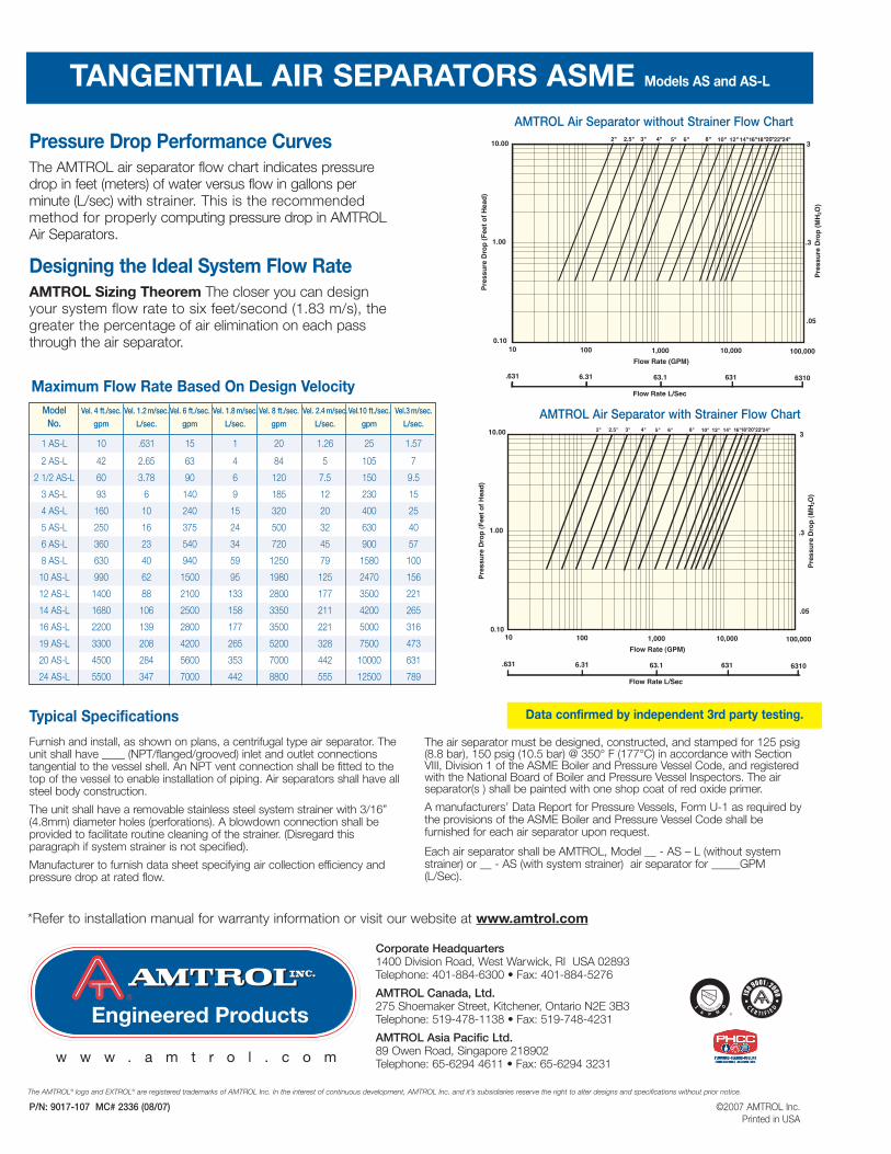
Pressure Drop Performance CurvesThe AMTROL air separator flow chart indicates pressuredrop in feet (meters) of water versus flow in gallons perminute (L/sec) with strainer. This is the recommendedmethod for properly computing pressure drop in AMTROLAir Separators.
Designing the Ideal System Flow RateAMTROL Sizing Theorem The closer you can designyour system flow rate to six feet/second (1.83 m/s), thegreater the percentage of air elimination on each passthrough the air separator.
10 100 1,000 10,000 100,000
.631 6.31 63.1 631 6310
Flow Rate (GPM)
Flow Rate L/Sec
10.00
1.00
0.10
Pre
ssu
re D
rop
(F
eet
of
Hea
d)
3
.3
.05
Pre
ssu
re D
rop
(M
H2O
)
AMTROL Air Separator with Strainer Flow Chart
AMTROL Air Separator without Strainer Flow Chart
Typical Specifications
Furnish and install, as shown on plans, a centrifugal type air separator. Theunit shall have ____ (NPT/flanged/grooved) inlet and outlet connectionstangential to the vessel shell. An NPT vent connection shall be fitted to thetop of the vessel to enable installation of piping. Air separators shall have allsteel body construction.
The unit shall have a removable stainless steel system strainer with 3/16”(4.8mm) diameter holes (perforations). A blowdown connection shall beprovided to facilitate routine cleaning of the strainer. (Disregard thisparagraph if system strainer is not specified).
Manufacturer to furnish data sheet specifying air collection efficiency and pressure drop at rated flow.
The air separator must be designed, constructed, and stamped for 125 psig(8.8 bar), 150 psig (10.5 bar) @ 350° F (177°C) in accordance with SectionVIII, Division 1 of the ASME Boiler and Pressure Vessel Code, and registeredwith the National Board of Boiler and Pressure Vessel Inspectors. The airseparator(s ) shall be painted with one shop coat of red oxide primer.
A manufacturers’ Data Report for Pressure Vessels, Form U-1 as required bythe provisions of the ASME Boiler and Pressure Vessel Code shall befurnished for each air separator upon request.
Each air separator shall be AMTROL‚ Model __ - AS – L (without systemstrainer) or __ - AS (with system strainer) air separator for _____GPM(L/Sec).
The AMTROL® logo and EXTROL® are registered trademarks of AMTROL Inc. In the interest of continuous development, AMTROL Inc. and it’s subsidiaries reserve the right to alter designs and specifications without prior notice.
®
Corporate Headquarters1400 Division Road, West Warwick, RI USA 02893Telephone: 401-884-6300 • Fax: 401-884-5276
AMTROL Canada, Ltd.275 Shoemaker Street, Kitchener, Ontario N2E 3B3Telephone: 519-478-1138 • Fax: 519-748-4231
AMTROL Asia Pacific Ltd.89 Owen Road, Singapore 218902Telephone: 65-6294 4611 • Fax: 65-6294 3231w w w . a m t r o l . c o m
Data confirmed by independent 3rd party testing.