for contract no. 12-0n2204 at 12-ora-23.8 identified … · identified by project id 121300182 ......
TRANSCRIPT
INFORMATION HANDOUT For Contract No. 12-0N2204
At 12-Ora-23.8
Identified by Project ID 121300182
AGREEMENTS
University of California at Irvine Memorandum of Understanding (MOU)
Audio Visual System Narrative
Caltrans District 12
Caltrans District 12 Page 1 of 39 AV System Narrative –CD 2014-March -31
Caltrans District 12 Audio Video System Narrative Bid Set Documents 2014-March-31
TABLE OF CONTENTS INTRODUCTION ........................................................................................................... 3 BASELINE SUMMARY................................................................................................. 3 General Guidlines ............................................................................................................ 6
Computer Room (RM. 125) ......................................................................................... 6 AV Systems Isolated Ground and Power Recommendations ...................................... 8 Design Criteria and Considerations ........................................................................... 10
AV Systems - Overview ................................................................................................ 12 CONTROL SYSTEM(S) ............................................................................................... 12
AV Network ............................................................................................................... 12 AV Control Hardware ................................................................................................ 13
AUDIO SYSTEMS ........................................................................................................ 14 Digital Signal Processor ............................................................................................. 14
VIDEO SYSTEMS ........................................................................................................ 16 Grass Valley Triaxis .................................................................................................. 16 Conference Video Switcher(s) ................................................................................... 17 IPTV ........................................................................................................................... 17
AV System – Room Summaries .................................................................................... 18 TRANSPORTATION MANAGEMENT CENTER ..................................................... 18
RM. 116 – Video Wall Displays ................................................................................ 18 RM. 123 – Video Wall Processing Room .................................................................. 20 RM. 116 – Transportation Management Center Ops Floor ....................................... 20 RM. 230 Visitor Corridor .......................................................................................... 21
LOCAL DISPLAYS AND CONTROL SCREENS ...................................................... 22 RM. 101 - Lobby........................................................................................................ 22 RM. 201 – Division Chief Traffic Operations Conference Room ............................. 22 RM. 231 – System Support Area ............................................................................... 23
LOCAL TOUCH SCREENS ......................................................................................... 24 RM. 108 – CHP Area Commander ............................................................................ 24 RM. 117 – Operations Shift Leader ........................................................................... 24 RM. 118 – TMC Operations Branch Chief ................................................................ 24 RM. 217 – Traffic Systems Development Branch Chief ........................................... 25 RM. 220 – Electrical Systems Branch Chief ............................................................. 25 RM. 247 – Traffic Operations Division Chief .......................................................... 25
911 Call Center .............................................................................................................. 26 RM. 112 – CHP Communications Supervisor ........................................................... 26
Caltrans District 12
Caltrans District 12 Page 2 of 39 AV System Narrative –CD 2014-March -31
RM. 113 – 911 CHP Call Center ............................................................................... 26 Message/Data Board ...................................................................................................... 27
RM. 123/RM. 116 ...................................................................................................... 27 RM. 242/243 .............................................................................................................. 27
CONFERENCE ROOMS .............................................................................................. 28 RM. 227/228 – Traffic System Development Lab..................................................... 29 RM. 242/243 – EOC-Training Rooms 1 & 2 ............................................................. 30 RM. 215 – Video Tel-Conference Room ................................................................... 32 RM. 213 – Briefing Room ......................................................................................... 34 RM. 143 – 1st Floor conference Room ...................................................................... 36
TOURGUIDE SYSTEM (WIRELESS) ........................................................................ 38 ALS/Tourguide System ............................................................................................. 38
REMOTE LOCATIONS INTERFACE ........................................................................ 38 UCI Interface System ................................................................................................. 38
INSTALLATION CONSIDERATIONS ....................................................................... 39 Demolition and Rebuild ............................................................................................. 39 Wire Removal ............................................................................................................ 39
Caltrans District 12
Caltrans District 12 Page 3 of 39 AV System Narrative –CD 2014-March -31
INTRODUCTION This document describes the existing AV systems installed at the Caltrans District 12 Transportation Management Center (TMC) and outlines a new design for a facility upgrade to take advantage of current and emerging technologies that will serve the facility for up to fifteen years in the future. This document is not a complete reference and must be reviewed in conjunction with the following documents:
1. Audiovisual Systems Scope of Work Specification 2. AV Systems Documents:
a. AV System Narrative (This Document) b. AV System Equipment List c. AV System Facility Impact Reports (Estimated Power and Heat Loads)
3. AV Systems Drawings: a. General Notes and Conditions b. Division of Responsibilities chart c. Junction Box-Wire Schedule d. Floor and Ceiling Plans e. Single Line Connection Diagrams f. Rack Elevations g. Typical Details
4. Crossover/Installation Plan
The equipment callouts provided herein are for reference only. Options for technology approaches are noted below. Prior to equipment procurement and shop drawings submittals, the AV Contractor shall verify current models of equipment listed and advise the Owner which models are suitable for use in this project that meet or exceed the design intent specified herein. The AV Contractor shall strive to use the most current model of equipment listed in the design specification provided it meets or exceeds the performance requirements. This document gives some general parameters for typical back of house requirements and outlines approaches. The AV System shall be designed to support the routing and viewing of multiple video/audio sources throughout the facility. The technology shall allow for future upgrades and expansion that will minimize equipment and infrastructure upgrade costs where possible. BASELINE SUMMARY Details of the current systems installed at the Caltrans District 12 Transportation Management Center are documented in the “As-Built” drawings. The following is an outline of the major components. The current system is based around three separate video switching systems running analog video signals, an audio switching system plus an overall control system. Additional subsystems for audio processing and assisted listening are also part of the overall setup. The first part of the system is centered on a Grass Valley Triaxis analog video switcher than routes all of the highway observation cameras installed in the field. Theses cameras are currently delivered to the facility either as an MPEG encoded stream via the ATMS network or a Standard Definition – Serial
Caltrans District 12
Caltrans District 12 Page 4 of 39 AV System Narrative –CD 2014-March -31
Digital Interface (SD-SDI) video signal where they are split off for delivery to other entities. The incoming camera signals are converted to analog, composite video by a series of Gecko transcoders then connected to the Grass Valley switcher for internal distribution to systems throughout facility as well as VHS tape based recording units.
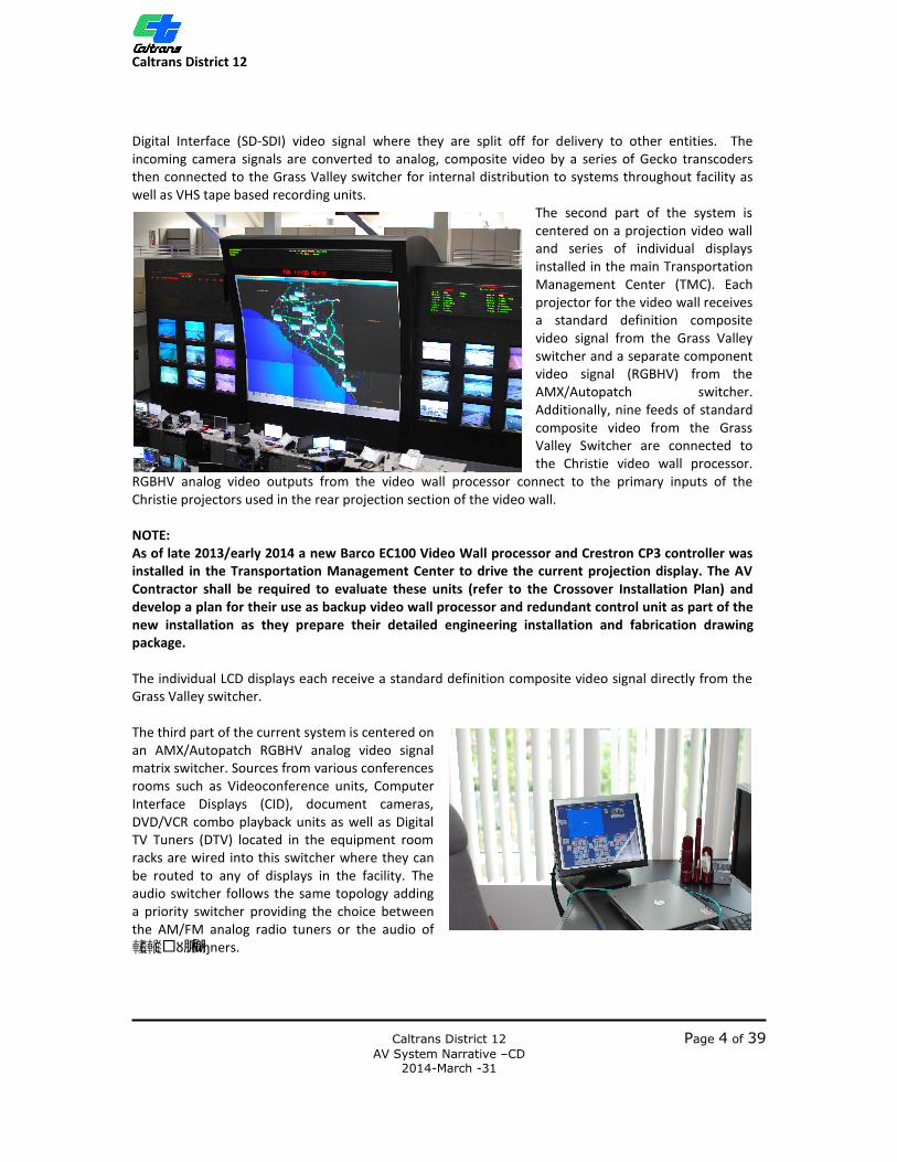
The second part of the system is centered on a projection video wall and series of individual displays installed in the main Transportation Management Center (TMC). Each projector for the video wall receives a standard definition composite video signal from the Grass Valley switcher and a separate component video signal (RGBHV) from the AMX/Autopatch switcher. Additionally, nine feeds of standard composite video from the Grass Valley Switcher are connected to the Christie video wall processor.
RGBHV analog video outputs from the video wall processor connect to the primary inputs of the Christie projectors used in the rear projection section of the video wall. NOTE: As of late 2013/early 2014 a new Barco EC100 Video Wall processor and Crestron CP3 controller was installed in the Transportation Management Center to drive the current projection display. The AV Contractor shall be required to evaluate these units (refer to the Crossover Installation Plan) and develop a plan for their use as backup video wall processor and redundant control unit as part of the new installation as they prepare their detailed engineering installation and fabrication drawing package. The individual LCD displays each receive a standard definition composite video signal directly from the Grass Valley switcher. The third part of the current system is centered on an AMX/Autopatch RGBHV analog video signal matrix switcher. Sources from various conferences rooms such as Videoconference units, Computer Interface Displays (CID), document cameras, DVD/VCR combo playback units as well as Digital TV Tuners (DTV) located in the equipment room racks are wired into this switcher where they can be routed to any of displays in the facility. The audio switcher follows the same topology adding a priority switcher providing the choice between the AM/FM analog radio tuners or the audio of 䡭䡮� 脈樃Ѐ Ѐ ȣ ɱners.

Caltrans District 12
Caltrans District 12 Page 5 of 39 AV System Narrative –CD 2014-March -31
The control component of the current system as installed is a Crestron Pro2. Crestron TPS 6000 and TPS 4000 touchscreens installed in various locations are connected to the control system via Crestron’s proprietary control protocol known as Crestnet. Each touch screen also receives a composite video signal from the Grass Valley switcher, an RGBHV signal from the AMX/Autopatch signal and an audio feed from the audio switcher. The Panasonic flat panel displays installed in conference rooms and other locations interface to the control system via Crestnet and a Crestron Crestnet to RS-232 convertor. This method allows the touchscreens to control the local AV equipment and preview video selections before switching them to the larger displays. A series of Crestron RF signal transmitters are installed throughout that provide the ability to use Crestron wireless remote controls. Each touchscreen, whether wired or wireless, is programmed with two modes of operation; regular “end user” and a “super user” that allows for greater access into the system. The current AV system in the Caltrans District 12 also includes a collection of audio processing equipment and auto-mixers that are used in conjunction with wireless microphone systems and assisted listening transmitters that provide audio to ceiling speakers installed in conference rooms and wireless headset receivers.
Block diagram of Video Switchers as Currently installed.
Caltrans District 12
Caltrans District 12 Page 6 of 39 AV System Narrative –CD 2014-March -31
GENERAL GUIDLINES Computer Room (RM. 125) The current AV systems are installed in Room #125, called the “Computer Room”. Four equipment racks are dedicated to AV systems that support the conference rooms and various flat panel displays installed throughout the facility. The system design shall seek to consolidate equipment as older technologies are replaced and utilize the current footprint for four new racks. Additional space for AV equipment racks is available behind the current video wall. It is required that the computer room shall have a climate controlled HVAC system designed and installed to maintain temperatures from 18°C (65°F) to 24°C (75°F) and 20% to 80% Relative Humidity, Non-Condensing.
Note: Since there are multiple AV and computer systems currently operating to serve the facility needs, an HVAC system is in place and presumed to meet these requirements. Facility impact reports have been provided throughout the design process and are part of the AV System Design documents. The AV Contractor shall continue to revise and update the Facility Impact requirements and share them with the Facility’s HVAC engineers to ensure that any AV system equipment specified does not exceed the system’s capacity.
It is recommended that the AV equipment located in the Computer Room and in each room be powered from a separately derived, isolation transformer, with an isolated (technical) ground AC power system. See page 8, AV Systems Isolated Ground and Power Recommendations for additional details.
Note: The Caltrans District 12 Transportation Management Center (TMC) has three levels of power systems. White outlets denote utility power and should not be used for AV equipment. Orange outlets denote Critical Power and Red outlets denote Essential Power. The AV Contractor shall coordinate with the Facility Electrical Engineer and the project Electrical Contractor to ensure that AV system equipment is connected to correct power source and that AC receptacles are moved or installed as per the AV System Design drawings.
All network distribution, control, AV source, monitoring, and signal switching; routing, processing, and transmitting equipment shall be located in the Computer Room (RM. 125) or in local conference room equipment racks. Ethernet over CAT6 Unshielded Twisted Pair (UTP), CAT6 Shielded Twisted Pair (STP) cable, and/or Multimode Fiber Optic shall provide communication links between the Computer Room and auxiliary equipment closets (if required) and peripheral equipment at remote equipment locations. Copper cable used for Ethernet communications shall follow standards set by the Facility. All cable used in this project is to be plenum rated. The equipment racks and remote equipment locations shall provide room for basic terminations, and in most cases, allow room for expansion of the system. Equipment racks to be provided shall follow standards set by the facility.
Caltrans District 12
Caltrans District 12 Page 7 of 39 AV System Narrative –CD 2014-March -31
General guidelines: • Provide minimum 36” clearance to the front, rear and at least one side of the AV Equipment
racks • Coordination required with Architect for equipment rack locations, conduit stub ups and
additional equipment racks needed by others.
The Facility utilizes a raised floor system for cable runs from RM. 125 (Computer Room) to equipment in RM. 116 (OPs floor). Cable runs from RM. 125 to the second floor shall go under the floor to the “in floor” conduit that connects RM. 116 to the IDF closet RM. 141. From there cable is to be routed up to RM. 245 on the second floor and distributed to the respective end devices. RM. 245 will include a secondary Ethernet Switch for connections to all second floor devices. Fiber optic cable for Video distribution shall pass through this room to the end devices in a single home run with no splices. In some instances routing through RM. 245 may exceed distances limitations as per the manufacturer’s performance specifications for particular devices and cable technology. The AV Contractor shall coordinate with the Electrical Contractor to determine the shortest path to these devices to ensure proper system performance.
See AV System drawings for an overview of network cable and video-over-fiber distribution.
During installation, Computer Room (RM. 125) power, high voltage terminations, and low voltage conduit and/or cable tray shall be provided by the General Contractor and/or their subcontractors. The AV Contractor shall provide the equipment rack assemblies and all low voltage terminations within those racks.
Caltrans District 12
Caltrans District 12 Page 8 of 39 AV System Narrative –CD 2014-March -31
AV Systems Isolated Ground and Power Recommendations The following is provided for informational purposes. It is noted that the Caltrans D12 facility has electrical power distribution system in place that meets or exceeds these recommendations. It is standard practice in our industry that AV systems use isolation transformers and isolated (technical) grounding to prevent interference from other systems installed in the facility. Examples of this practice can be found at http://www.middleatlantic.com/power.htm.
It is standard practice that the isolation transformers are specified and designed into the system by the Electrical Engineer (EE) based upon the estimated power loads provided and supplied as part of the Facility Impact Estimated Power and Heat Load reports.
Electrosonic recommends using an isolation transformer and isolated ground between all AVC system outlets and the first breaker panel after the transformer to prevent any potential electrical interference in the audio and video systems and to maintain the highest quality presentation. Without using a separately derived power source (transformer) for all AVC show system racks, and field equipment such as projectors and flat panel displays, there is the potential for interference from electric motors used in Show Action Equipment (SAE), the HVAC systems, or other subsystem electronics that we cannot be aware of at this time. The long history of successful implementations of isolated grounding systems as outlined in the document referenced above provide us the confidence that this is the best approach.
Although Uninterruptable Power Supplies (UPS) have been specified, they are intended to maintain power to computer based equipment in the event of voltage sags or blackouts for a short duration, and to allow the safe shutdown of all systems if the blackout condition lasts. All mission critical systems, such as control computers, audio interfaces, computer screens installed in equipment racks shall be on a dedicated uninterruptable power supply (UPS) sized to provide adequate run-time power to the serving equipment. All video wall components and touch screens utilized by the AV system shall be connected to the critical power systems provided at the CalTrans Facility. The Owner shall provide directions at the time of installation. Refer to the AV System Design Drawings and Documentation for further information regarding computer room layout, electrical grounding requirements and estimated power and heat loads.

Caltrans District 12
Caltrans District 12 Page 9 of 39 AV System Narrative –CD 2014-March -31
Please Note: The AV System Design Documents and Drawings specify cable for the AV system only. Conduit routing and cable tray design is to be done by the project Electrical Engineer. Conduit and cable tray installation, high voltage power for equipment shall be provided and installed by the General Contractor and/or their subcontractors. Low voltage cable supply, installation and termination shall be the responsibility of the AV Contractor. These costs should be clearly reflected in the AV Contractor’s bid response. During installation, all AV system low voltage cable shall be installed with a minimum of 10 ft. extra past the termination point indicated by the AV junction boxes on the plan drawings and shall provide enough length of cable to reach past the intended termination point in the relative equipment rack. Information regarding junction box installation, heights and conditions and exceptions is provided in a junction box scheduled included in the drawing package.

Caltrans District 12
Caltrans District 12 Page 10 of 39 AV System Narrative –CD 2014-March -31
Design Criteria and Considerations The Caltrans District 12 AV Systems design shall be based on the following criteria and considerations:
1. All image, audio, and control source (PC or video player based) distribution, switching, routing, processing, and transmitting shall be centrally located in the Computer Room (RM. 125) and distributed to the common areas. Conference rooms shall have local source devices and local presentation switcher/controllers.
2. Fiber optic, Shielded Twisted Pair (STP), Unshielded Twisted Pair (UTP) and other low-voltage
cabling infrastructure shall provide communication and signal links between the Computer room (RM. 125) and equipment at remote locations.
Note: The use of Fiber optic cable for point to point video connections ensures that bandwidth will be available for high resolution video signals being used today and for even greater resolution signals that may be implemented over the lifespan of this system. This also circumvents the possibility of having copper cable runs that exceed the length specification for transmitting high resolution signals where the direct routes through the Facility are not possible.
Fiber cable in conjunction with AV Extender/Receiver pairs provide the advantage of being able have audio and control signals transported to end devices when needed over the same cable. Multicore fiber cable ensures there are spares cores available in case of damage during installation or additional equipment that may be implemented in the future.
3. Infrastructure in the Computer Room (RM. 125) and remote equipment locations shall include: • Fiber optic or CAT6 connectivity points to accommodate present and future Local Area
Network (LAN) needs for AV system demands • Layer 3 Managed Ethernet switches for simple and rapid signal routing • Gigabit infrastructure for high bandwidth data management • Dedicated point to point Fiber optic or CAT5e drops for image distribution requirements,
such as Video over category cable • Multi Core Fiber-Optic (Multi-Mode) drops for image, audio, and control distribution
requirements
4. Control shall be dedicated system based, be configurable for redundant control applications, have the ability to accept digital I/O for interfacing relays control input sensors, and be capable of controlling serial RS-232, 422, 485, SMPTE Time-Code, DMX-512, Midi, ArtNet and Ethernet TCP/IP.
5. The AV system shall have an astronomical clock tracking time of day, month, and year. 6. The AV system shall be capable of receiving faults and error logs, and capable of providing flags
to the operations department for performing servicing and/or maintenance.
Caltrans District 12
Caltrans District 12 Page 11 of 39 AV System Narrative –CD 2014-March -31
7. It has been confirmed with the City of Irvine that that is no requirement for the AV systems to be muted via fire alarm contact closures. Audio and video shall continue to operate in the event of a building alarm event.
8. Projected and/or displayed video content shall be vivid, immersive, powerful, brilliant and free
of artifacts.
9. The specified technology shall allow for future upgrades and expansion that will minimize equipment and infrastructure upgrade costs.
10. The AV Systems shall implement a network-based system architecture allowing the owner and/or the technical director to change, maintain and troubleshoot many of the system features from remote locations, such as home or office PC’s. Managed network switches using Virtual Local Area Networks (VLAN) shall maintain the integrity of the numerous audio signals, while adding flexibility to the equipment rack placement and wiring demands, and simplifying the fabrication and termination of the system.
11. All AV system equipment shall be new and shall be permanently labeled with the
manufacturer’s name, model number and serial number. All active circuitry shall be rated for continuous use, 24/7 operation. Custom-built devices shall be constructed of materials and components that meet or exceed AV specification requirements and shall only be used when no commercially made equivalent is available. Finish colors of any equipment in public view shall be approved by the Owner or Architect. Select equipment can be custom painted if necessary.
12. The Audio delivery system shall be multi-channel point source based.
13. The Audio DSP processing system shall be capable of supporting multiple audio channels allowing audio to be routed independently of video signals if required.
14. All mission critical systems, such as control computers, and/or audio interfaces, computer screens, and touch screens utilized shall be on a dedicated, uninterruptable power supply (UPS), sized to provide adequate run-time power to the serving equipment so that a proper shut-down can be initiated. Close coordination shall be required with the facility to determine the power requirements and emergency power transfer for all field installed displays and equipment.
15. All Audio, Video, and Control equipment that are not local to a specific area shall be rack
mounted within professional grade AV Racks in corresponding equipment rooms. The equipment racks and/or remote equipment locations shall provide room for basic terminations and allow, where possible, room for expansion of the system.

Caltrans District 12
Caltrans District 12 Page 12 of 39 AV System Narrative –CD 2014-March -31
AV SYSTEMS - OVERVIEW The equipment and cable based on analog standards can no longer keep pace with high resolution video signals available today and to come in the future. While the current systems provide the ability to route any video source to any display, there is a patch work of differing signal types that adds a level of complication to the operation. The recommendations below are presented to meet the following criteria:
• The system shall be designed with technologies that will last for up to fifteen years. • The infrastructure/cable shall support future upgrades and be able to adapt to anticipated
advancements in technology without requiring major upgrades within the fifteen year window.
• The Control system(s) shall be upgraded to the latest versions available that offer more powerful instruction processing, TCP/IP connections to other equipment either currently in use of part of the upgrade as well as small Power-over-Ethernet (POE) touch panels that can replace existing button panels.
• Audio routing and processing systems shall be consolidated into a single comprehensive system that shall recreate the existing functionality with virtual devices in a Digital Signal Processor as well as expanding the capabilities for routing audio whether along with or separate from the video signals.
• Video systems shall be consolidated streamlined simplified where applicable while being able to provide a video signal routing capability greater that what is currently available.
CONTROL SYSTEM(S) The control system shall be comprised of two primary elements. The first is to integrate all of the devices on a gigabit Ethernet Network built around layer 3 managed switches. The second is the new generation of control computer/system, hardware. AV Network – All AV equipment with Local Area Network (LAN) ports and/or any AV data programming ports installed throughout the facility shall be connected to a series of Layer 3 managed switches installed in the Computer Room (RM. 125), the Rear Projection Room (RM. 123), the IDF closet on the second floor (RM. 245) and in local presentation racks in the various conference rooms. Each switch shall be capable of data transfers at 10/100/1000 Mbps on all ports. Ethernet switches shall be interconnected with fiber optic cable to create a single AV network. Redundant connections shall be incorporated to ensure critical rooms can remain connected to the AV network in the event of cable failures. Media converters shall be used to interface the Ethernet signals over the fiber optic cable to the remote equipment and programming ports if the cable distances exceed the Ethernet limit of 330 ft. (100m). The AV network can utilize at least one connection to the facility network for remote access. This allows designated facility computers to be granted access to the AV systems. Custom programmed screens that allow control and monitoring of the AV system. The Facility’s’s IT department can allow access from the outside into the AV Network for remote trouble shooting. This is an operational management choice to be made in the future.

Caltrans District 12
Caltrans District 12 Page 13 of 39 AV System Narrative –CD 2014-March -31
In addition, the current use of the Crestron RF Gateways should be removed. The equipment is obsolete and there is more advantage to replacing the transmitters with Wireless Access Points (WAP). Custom APPs can be installed on wireless devices such as iPhones and iPads that provide control screens. This network-based system architecture shall allow the Owner and the AV Integrator to change, maintain and troubleshoot many of the system features from remote locations. Multiple managed network switches using Virtual Local Area Networks (VLAN) shall maintain the integrity of the numerous signals, add flexibility to the equipment rack placement and wiring demands, and simplify the fabrication and termination of the system.
NOTE: The AV Contractor shall maintain ongoing discussions and coordination with the Facility IT staff in order to address the Owner’s IT needs in regards to the Facility network at large throughout the installation process. The AV Network outlined above is a preferred installation method that allows the AV Contractor to build and test systems in their shop before delivery to site and allows them to continue testing and programming once the AV equipment racks are installed and operational. Caltrans has stated their preference that follows this model of creating and maintaining the AV Network as separate from the Facility Network. There may be instances where facility computers may require access to certain pieces of AV hardware. This design shall work to identify those instances and the AV Contractor shall work with the Caltrans IT department to ensure the functionality can be provided without violating any network policies that are in place.
AV Control Hardware – Control for the current system is centered on a pair of Crestron Pro controllers, Crestron TPS 6000 touchscreens, Crestnet distribution blocks and Crestron Audio volume controllers. The recommended upgrade path is to utilize the latest generation of network based control hardware. The new generations of control hardware employ faster processors that are capable of issuing more instructions per second than previous models. A network based system will provide a greater level of control to a greater number of devices ensuring that the system will remain a viable piece of hardware for anticipated 15 year lifespan of this design. Considering the projected demands, the recommended AV Control System is the Crestron 3-Series Control System®. This model provides the TCP/IP control capabilities required for current equipment as well as the future. The CP3 retains Crestnet capability allowing this project to maintain this functionality where desired and it offers easy interface with building management systems through the BACNET protocol should this become a requirement in the future. Recommended Equipment: § Cisco Small Business 500 Series or Catalyst Managed Switches
o Must meet Caltrans standards § Cisco Wireless Access Points (As Per CalTrans Standards) § Fiber to Copper Media Convertors (if required) § Owner Furnished Computer for Basic Programming § Crestron CP3 3-Series Control System

Caltrans District 12
Caltrans District 12 Page 14 of 39 AV System Narrative –CD 2014-March -31
AUDIO SYSTEMS Currently the audio systems in the Caltrans District 12 facility are built on three separate components, the AMX/Autopatch Audio Switcher; Shure Auto Mixers and Lectrosonics Digital Signal Processors with dedicated volume controllers feeding into multichannel amplifiers driving ceiling speakers in corridors and conference rooms, the EOC training center and the Transportation Management Center (TMC); and an assisted listening system comprised of wireless microphones, receivers, an automixer and Telex wireless audio transmitters and headsets. Outputs from the AMX/Autopatch Audio Switcher are connected by cable running directly to the flat panel displays where small Radio Design Labs amplifiers drive the local display speakers. This and the use of aging equipment provide the opportunities for the upgrades and improvements noted below. Digital Signal Processor – The AMX/Audio Patch audio switcher shall be eliminated. The AV System Design/Upgrade shall use a network based audio and Integrated System Platform that provides all the audio routing, processing control and monitoring for a facility and designed specifically for the rigorous requirements of large-scale applications. All of the Shure automixers, Lectrosonics processors and Crestron Volume control Cards shall be eliminated and their functions will be recreated inside the DSP system. This will provide a comprehensive integration of all audio signals in the system and add functionality that the current system does not offer as well as provided easy upgrade paths and expandability by adding Input/Output frames and cards as needed. Outputs from audio sources shall be connected to the DSP for routing and equalization before being distributed to the respective amplifiers. The DSP system shall be network enabled, provide a single software interface for programming. The DSP system shall provide a means of distributing digital audio from the central processors to analog breakout boxes located near the amplifiers. The DSP system shall be programmed to direct discrete sources to the various zones as well as allow for an audio file or signal to be routed to all zones. The DSP System shall employ a standards-based, low-latency Gigabit Ethernet network implementation and be responsible for audio routing between devices ensuring that all signals are transmitted from source to destination in less than 1/3rd of a millisecond. The DSP System Shall be capable of transmitting a minimum of 128 audio input channels and 128 audio output channels to and from the main processor. The DSP System shall have audiophile quality, 32-bit floating point distribution and high performance A/D and D/A converters resulting in outstanding fidelity and a total system latency – any input to any output with up to 10 network switch hops – of less than 2.5 milliseconds. In addition to low latency distribution, the DSP system shall also support long-haul IP streaming of audio over Wide Area Networks (WAN) as well as auto-discovery and configuration of end nodes.
Note: At this time there is no direct audio interface required between the Facility’s existing paging systems.

Caltrans District 12
Caltrans District 12 Page 15 of 39 AV System Narrative –CD 2014-March -31
All of the currently used amplifiers shall be up graded to models that directly interface to the DSP system and provide complete control and monitoring of their function. Speakers shall be replaced with models similar to those currently installed in the facility.
Caltrans District 12
Caltrans District 12 Page 16 of 39 AV System Narrative –CD 2014-March -31
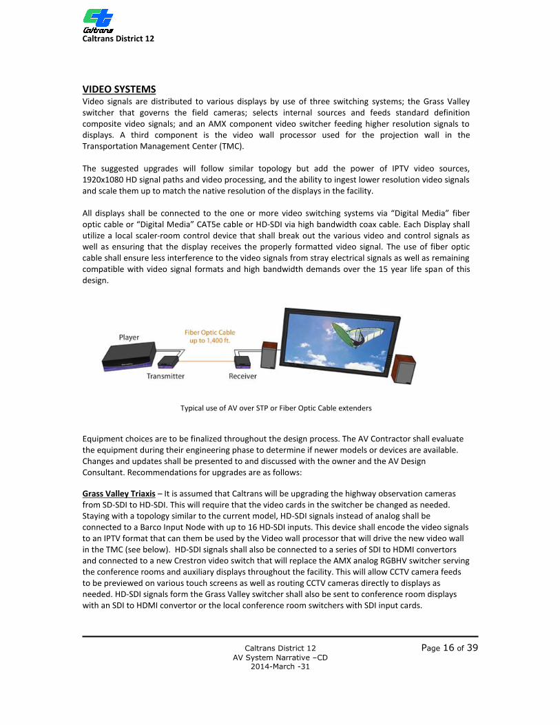
VIDEO SYSTEMS Video signals are distributed to various displays by use of three switching systems; the Grass Valley switcher that governs the field cameras; selects internal sources and feeds standard definition composite video signals; and an AMX component video switcher feeding higher resolution signals to displays. A third component is the video wall processor used for the projection wall in the Transportation Management Center (TMC). The suggested upgrades will follow similar topology but add the power of IPTV video sources, 1920x1080 HD signal paths and video processing, and the ability to ingest lower resolution video signals and scale them up to match the native resolution of the displays in the facility. All displays shall be connected to the one or more video switching systems via “Digital Media” fiber optic cable or “Digital Media” CAT5e cable or HD-SDI via high bandwidth coax cable. Each Display shall utilize a local scaler-room control device that shall break out the various video and control signals as well as ensuring that the display receives the properly formatted video signal. The use of fiber optic cable shall ensure less interference to the video signals from stray electrical signals as well as remaining compatible with video signal formats and high bandwidth demands over the 15 year life span of this design.
Typical use of AV over STP or Fiber Optic Cable extenders
Equipment choices are to be finalized throughout the design process. The AV Contractor shall evaluate the equipment during their engineering phase to determine if newer models or devices are available. Changes and updates shall be presented to and discussed with the owner and the AV Design Consultant. Recommendations for upgrades are as follows:
Grass Valley Triaxis – It is assumed that Caltrans will be upgrading the highway observation cameras from SD-SDI to HD-SDI. This will require that the video cards in the switcher be changed as needed. Staying with a topology similar to the current model, HD-SDI signals instead of analog shall be connected to a Barco Input Node with up to 16 HD-SDI inputs. This device shall encode the video signals to an IPTV format that can them be used by the Video wall processor that will drive the new video wall in the TMC (see below). HD-SDI signals shall also be connected to a series of SDI to HDMI convertors and connected to a new Crestron video switch that will replace the AMX analog RGBHV switcher serving the conference rooms and auxiliary displays throughout the facility. This will allow CCTV camera feeds to be previewed on various touch screens as well as routing CCTV cameras directly to displays as needed. HD-SDI signals form the Grass Valley switcher shall also be sent to conference room displays with an SDI to HDMI convertor or the local conference room switchers with SDI input cards.

Caltrans District 12
Caltrans District 12 Page 17 of 39 AV System Narrative –CD 2014-March -31
Conference Video Switcher(s) – The current AMX/Autopatch RGBHV switcher shall be replaced with a new digital video matrix switcher that is capable of ingesting different signal types, (analog and digital) then outputting into a digital video format. The new generations of digital media switchers provide this transcoding capability. In addition they use extender boxes placed near the displays and connect back to the main switcher via fiber optic cable or CAT5e cable. Various control and audio signals can be carried along these cables thus minimizing the cable infrastructure requirements. The new system shall employ a (64) input by (64) output switcher in the equipment room to handle all of the source equipment installed there along with a set of feeds from the Grass Valley switcher. Conference rooms, 143, 215, 213, the lab (RM. 227) and the EOC Training rooms 242/243 shall be equipped with local presentation switchers that directly ingest local sources such as document cameras, DVD/Hard Disc recorders, computer interfaces, video conference devices, wireless video receiver, and HD-SDI signals from the Grass Valley switcher and wall plates for additional equipment. Outputs from these switchers drive the local displays directly. Additional outputs from these local presentation switchers shall connect back to the Computer Room (RM.125) allowing source equipment to be routed to other rooms as needed. Secondary HDMI inputs on the various flat panel displays can be fed directly from the Grass Valley switcher in the Computer Room (RM.125). Standalone displays such as the lobby and the support room on the second floor shall be fed directly from the switcher in the Crestron switcher in the Computer Room (RM.125). Touch screens installed in various offices and rooms throughout the facility shall employ a “Graphics Engine” that shall connect to two outputs of a video switch. The screen shall connect to the Graphic engine via Digital Media cable. This cable shall carry all video and control signal to and from the touch screen and shall provide the ability to preview two separate video signals.
IPTV – In addition to the above hardwired methods, the design upgrade proposes leveraging the power of IPTV protocols to provide a greater level of flexible routing. At least part of the Caltrans CCTV Highway observation cameras are transmitted to the facility as IPTV encoded video streams. By using decoder boxes or using ITPV decoder cards in video switcher or video wall processors, the system can scan the network and ingest these video streams for display on the video wall or other systems. Computers and servers running a content management systems software shall be able to seek out these signals, configure desired views on desktop computers. These views can be displayed on the large video wall in the TMC, shared across the Local Area Network (LAN), or shared across the Wide Area Network (WAN) with other Caltrans facilities. This will require close coordination with the Facility’s IT department to ensure there is an understanding of bandwidth, functionality and security.
Caltrans District 12
Caltrans District 12 Page 18 of 39 AV System Narrative –CD 2014-March -31
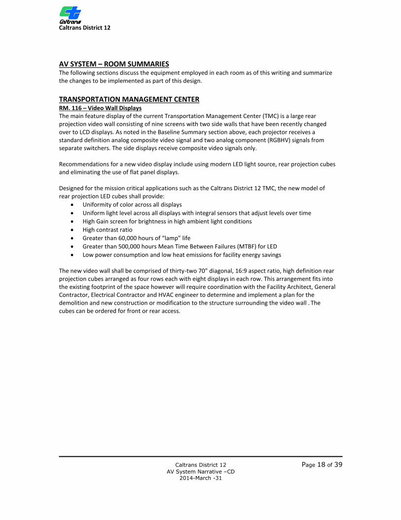
AV SYSTEM – ROOM SUMMARIES The following sections discuss the equipment employed in each room as of this writing and summarize the changes to be implemented as part of this design. TRANSPORTATION MANAGEMENT CENTER RM. 116 – Video Wall Displays The main feature display of the current Transportation Management Center (TMC) is a large rear projection video wall consisting of nine screens with two side walls that have been recently changed over to LCD displays. As noted in the Baseline Summary section above, each projector receives a standard definition analog composite video signal and two analog component (RGBHV) signals from separate switchers. The side displays receive composite video signals only. Recommendations for a new video display include using modern LED light source, rear projection cubes and eliminating the use of flat panel displays. Designed for the mission critical applications such as the Caltrans District 12 TMC, the new model of rear projection LED cubes shall provide:
• Uniformity of color across all displays • Uniform light level across all displays with integral sensors that adjust levels over time • High Gain screen for brightness in high ambient light conditions • High contrast ratio • Greater than 60,000 hours of “lamp” life • Greater than 500,000 hours Mean Time Between Failures (MTBF) for LED • Low power consumption and low heat emissions for facility energy savings
The new video wall shall be comprised of thirty-two 70” diagonal, 16:9 aspect ratio, high definition rear projection cubes arranged as four rows each with eight displays in each row. This arrangement fits into the existing footprint of the space however will require coordination with the Facility Architect, General Contractor, Electrical Contractor and HVAC engineer to determine and implement a plan for the demolition and new construction or modification to the structure surrounding the video wall . The cubes can be ordered for front or rear access.
Caltrans District 12
Caltrans District 12 Page 19 of 39 AV System Narrative –CD 2014-March -31
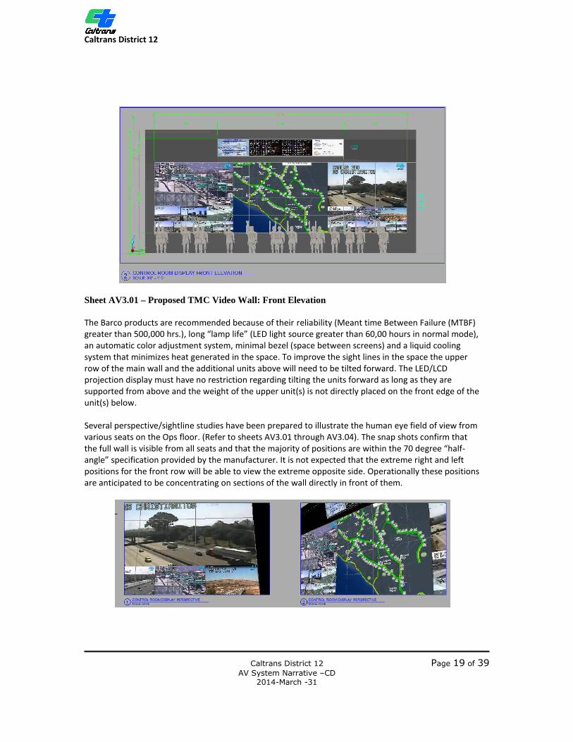
Sheet AV3.01 – Proposed TMC Video Wall: Front Elevation The Barco products are recommended because of their reliability (Meant time Between Failure (MTBF) greater than 500,000 hrs.), long “lamp life” (LED light source greater than 60,00 hours in normal mode), an automatic color adjustment system, minimal bezel (space between screens) and a liquid cooling system that minimizes heat generated in the space. To improve the sight lines in the space the upper row of the main wall and the additional units above will need to be tilted forward. The LED/LCD projection display must have no restriction regarding tilting the units forward as long as they are supported from above and the weight of the upper unit(s) is not directly placed on the front edge of the unit(s) below. Several perspective/sightline studies have been prepared to illustrate the human eye field of view from various seats on the Ops floor. (Refer to sheets AV3.01 through AV3.04). The snap shots confirm that the full wall is visible from all seats and that the majority of positions are within the 70 degree “half-angle” specification provided by the manufacturer. It is not expected that the extreme right and left positions for the front row will be able to view the extreme opposite side. Operationally these positions are anticipated to be concentrating on sections of the wall directly in front of them.

Caltrans District 12
Caltrans District 12 Page 20 of 39 AV System Narrative –CD 2014-March -31
The AV Contractor shall work closely with the General Contractor to first dismantle the existing wall and displays them implement the video wall mounting as per plans to be provided by Draper Design. The GC shall build the surrounding wall and finish cladding. The AV Contractor shall review the “Crossover/Installation” document included with the AV System Design documents for an understanding of the temporary systems that must be put in place before demolition of the video wall can begin. RM. 123 – Video Wall Processing Room A new video wall processor with digital input cards as well as IPTV receiver cards shall drive the video wall. The video wall processor shall allow any number of display configurations across all of the displays by using “window” or “perspective” presets. The processer shall ingest a set number of digital video inputs from the Grass Valley switch, a server running the ATMS client software. To leverage the power of IPTV streams, the video wall processor can include IPTV decoder cards that can switch between any available IPTV streams that are placed on the network. This can include cameras directly encoded or desktop computers running software that allows the creation of custom views to be easily shared among other local computers, the local video wall, or other facilities running the same software. The video wall processing system shall require a management server, media management hardware, output nodes and input nodes. The system shall offer several ways of accessing and presenting video. The AV Installer shall work closely with the manufacturer to refine the equipment selections and to program the system to meet the needs of the Owner and the work flow requirements of the staff working on the operations floor. RM. 116 – Transportation Management Center Ops Floor RM. 116 currently has (7) Crestron Touch screen control panels installed at key positions, (6) Flush mounted speakers in the left and right walls, local video source connected back to the analog video switcher. The Ops floor workstations have Pelco quad monitors for preview traffic cameras and other computer systems with screens that are not part of this AV Upgrade scope. These items will remain to be integrated into the new furniture that is under consideration at the time of this writing and may already be installed at the time of the AV System upgrade installation. The current system also includes a Crestron RF Gateway and Wireless mic antennae installed as part of the control system and Tourguide system.
The current system has the ability to connect (7) computers into the video switcher systems using Extron video extenders. This function is not used in the present system and these Extron units will be removed.
The new AV Systems upgrade shall include a Digital Media transmitter that shall allow for connection of a local Blu-ray disc player. The video signal shall connect to the 64x64 Crestron Switcher in RM. 125. Control is back channeled over this same fiber connection providing control from the administrator’s touch screen.
The Ops floor will have (8) new Crestron Touchscreens installed and programmed to the Owner’s requirements for each station. Functionality shall be similar across all screens. The AV Installer shall work with the Owner to customize each screen for the tasks of each station if needed. All screens shall have a password protected “super user” admin privileges mode allowing for deeper technical control of
Caltrans District 12
Caltrans District 12 Page 21 of 39 AV System Narrative –CD 2014-March -31
the video wall systems and local AV equipment. This functionality shall apply to all touch screen noted in throughout.
The users working in the space have several screens at their workstations. The AV Installer, working with the Owner shall ensure that the touch screen interfaces are programmed to be clean, clear and intuitive for the end users in order to enhance their work flow.
Each of the touch screens shall be driven from a Crestron Digital Graphic Engine (Crestron DGE2) installed in RM. 125 and connected to via Crestron Digital Media 8G+ cable. Each touch screen shall have two video preview windows and the ability to monitor any source connected to the 64x64 Crestron switcher. Each video screen shall have the ability to direct highway camera feeds to large “windows” defined on the TMC video wall.
Each touch screen shall have the ability to route the audio from any source connected to the Crestron video switcher and the QSC Digital Signal Processor (DSP) to the speakers in the room. Audio can be programmed to follow certain video selections from a designated screen or it can be programmed to be completely separate allowing for multiple video images to be previewed or displayed on the video wall while switching between the audio sources desired. The AV contractor shall work with the Owner to program the desired switching functionality.
The Crestron RF gateway transmitter associated with this space shall be removed. A Wireless Access Point (WAP) installed in RM. #116 shall allow remote panel control of the devices in RM. #116. Using a customized Crestron APP for iPad or other tablet device, the staff will be able enter the space and control the local equipment.
The Wireless Mic antenna, Telex Transmitter and associated wires shall be removed and replaced with a Sennheiser multichannel Tour guide wireless mic and personal receiver system.
Installation Considerations: • Analog wires to be removed when no longer needed • Custom touch screen programming, refinement and modifications to meet the
Owner’s desired functionality including a regular “End User” screen and a “Super User” screen
RM. 230 - Visitor Corridor RM. 230 is on the second floor and is the balcony that traverses the building at the rear of the TMC Ops Center (RM. 116). There are currently four JBL flush mounted ceiling speakers installed along the corridor.
The AV System Design/Upgrade specifies that four new flush mounted ceiling speakers are to be installed here. The speakers shall be feed from a single amplifier channel of a 70 volt amp installed in the computer room (RM. 125). The DSP system and control system shall be programmed to direct whatever audio source is hear in the RM. 116 speakers to the RM. 230 speakers. The control screen shall have a separate volume control for RM. 230 allowing the staff to balance the sound levels.
Installation Considerations: • Replace current speaker wire with new wire as per the Junction box and cable
schedule in the AV System Design drawings. • Custom touch screen programming, refinement and modifications to meet the
Owner’s desired functionality including a regular “End User” screen and a “Super User” screen

Caltrans District 12
Caltrans District 12 Page 22 of 39 AV System Narrative –CD 2014-March -31
LOCAL DISPLAYS AND CONTROL SCREENS RM. 101 - Lobby The Lobby currently has a 55” Panasonic Plasma display connected to the Autopatch router via RGBHV analog video signals. Audio is connected to small RDL amplifier that drives external speakers. Control of the display is via an external Crestron control box and utilizes the Crestron RF gateway and a Crestron wireless touch panel that allows staff to enter the space and make the desired changes. Wireless microphone antennae and a Telex wireless Audio Transmitter are installed in the ceiling above the adjacent room (RM. 145) as part of a “tour guide” audio system. The AV System Design/Upgrade replaces the plasma display with a 55” LED/LCD display that consumes less power and presents a clearer, brighter picture. Video shall be fed to this display from the Crestron 64x64 Digital Media Switcher in RM. 125 via fiber optic cable that connects to a local Crestron room controller/scaler. This method reduces the overall cable requirements to the display location, combines video processing, audio delivery and control signals all over one cable while maintaining a high quality digital video signal. The Crestron RF gateway transmitters associated with this space shall be removed. A new Cisco wireless access point shall be installed in the lobby that connects back to the AV network switch in RM. 125. Using a customized Crestron APP for iPad or other tablet device, the staff will again be able enter the space and control the local equipment. The Wireless Mic antenna, Telex Transmitter and associated wires shall be removed and replaced with a Sennheiser multichannel Tour guide wireless mic and personal receiver system.
Installation Considerations: • Analog wires to be removed when no longer needed • Develop mobile APP (Crestron) to meet the Owner’s function requirements
RM. 201 – Division Chief Traffic Operations Conference Room RM. 201, the outer reception area and conference space currently has a 55” plasma display installed with cable for analog video signals sourced from the Autopatch router and the Grass Valley Switcher. Audio is connected to small RDL amplifier that drives external speakers. A portable AV cart with a CRT TV and Video player are used at the conference table when needed. RM. 247 has one Crestron touchscreen installed that provides video preview and control of the display in RM. 201.
The AV System Design/Upgrade replaces the plasma display with a 55” LED/LCD display that consumes less power and presents a clearer, brighter picture. Video shall be feed to this display from the Crestron 64x64 Digital Media Switcher in RM. 125 via fiber optic cable that connects to a local Crestron room controller/scaler. This method reduces the overall cable requirements to the display location, combines video processing, audio delivery and control signals all over one cable while maintaining a high quality digital video signal. The AV System Design/Upgrade does not call for any additional video or audio processing equipment in this space or any replacements for the portable AV cart and its associated equipment. One Blu-Ray DVD play shall be provided as loose equipment for use in this space.
Caltrans District 12
Caltrans District 12 Page 23 of 39 AV System Narrative –CD 2014-March -31
Installation Considerations: • Analog wires to be removed when no longer needed • Custom touch screen programming, refinement and modifications to meet the
Owner’s desired functionality including a regular “End User” screen and a “Super User” screen
RM. 231 – System Support Area RM. 231 currently has a 55” Panasonic Plasma display connected to the Autopatch router via RGBHV analog video signals. Audio is connected to small RDL amplifier that drives external speakers. Control of the display is via a wall mounted Crestron touch screen.
The AV System Design/Upgrade replaces the plasma display with a 55”LED/LCD display that consumes less power and presents a clearer, brighter picture. Video shall be fed to this display from the Crestron 64x64 Digital Media Switcher in RM. 125 via fiber optic cable that connects to a local Crestron room controller/scaler. This method reduces the overall cable requirements to the display location, combines video processing, audio delivery and control signals all over one cable while maintaining a high quality digital video signal.
External speakers shall be powered from the internal amplifier of the display and a new touchscreen shall be installed with a custom screen allowing for control of the display and source selection.
The AV system upgrade specifies replacing the touch screen with a Crestron V15 touchscreen driven by a Crestron DGE2 touchscreen engine installed in RM. 125. Creston Digital Media 8G+ Cable from RM. 125 shall connect the two devices. Two outputs from the main switcher in the RM.125 connected to the DGE shall be available in preview windows programed in the new touchscreen. The user shall be able to choose from any available video source and route it the display. The AV Installer shall work with the Owner to create the Graphic User Interface (GUI) and program the desired functionality of this screen. The Crestron RF gateway transmitters associated with this space shall be removed. A new Cisco wireless access point shall be installed in the space that connects back to the AV network switch in RM. 125. Using a customized Crestron APP for iPad or other tablet device, the staff will be able enter the space and control the local equipment.
Installation Considerations: • Analog wires to be removed when no longer needed • Custom touch screen programming, refinement and modifications to meet the
Owner’s desired functionality including a regular “End User” screen and a “Super User” screen
Caltrans District 12
Caltrans District 12 Page 24 of 39 AV System Narrative –CD 2014-March -31
LOCAL TOUCH SCREENS RM. 108 – CHP Area Commander RM. 108 currently has one Crestron touchscreen providing preview feeds of the highway CCTV Highway cameras from the Grass Valley switcher and various sources from the Autopatch router.
The AV System Design/Upgrade specifies replacing the touch screen with a Crestron V15 driven by a Crestron DGE2 touchscreen engine installed in RM. 125. Creston Digital Media 8G+ Cable from RM. 125 shall terminate at a wall plate and allow the touch screen to be disconnected. The touch screen shall have two preview windows for viewing sources connected to the new Crestron 64x64 switcher. The AV Installer shall work with the Owner to create the Graphic User Interface (GUI) and program the desired functionality of this screen.
Installation Considerations: • Analog wires to be removed when no longer needed • Custom touch screen programming, refinement and modifications to meet the
Owner’s desired functionality including a regular “End User” screen and a “Super User” screen
RM. 117 – Operations Shift Leader RM. 117 currently has no equipment.
The AV System Design/Upgrade specifies adding a touch screen with a Crestron V15 driven by a Crestron DGE2 touchscreen engine installed in RM. 125. Creston Digital Media 8G+ Cable from RM. 125 shall terminate at a wall plate and allow the touch screen to be disconnected. The touch screen shall have two preview windows for viewing sources connected to the new Crestron 64x64 switcher. The AV Installer shall work with the Owner to create the Graphic User Interface (GUI) and program the desired functionality of this screen.
Installation Considerations: • Analog wires to be removed when no longer needed • Custom touch screen programming, refinement and modifications to meet the
Owner’s desired functionality including a regular “End User” screen and a “Super User” screen
RM. 118 – TMC Operations Branch Chief RM. 118 currently has one Crestron touchscreen providing preview feeds of the highway CCTV Highway cameras from the Grass Valley switcher and various sources from the Autopatch router.
The AV System Design/Upgrade specifies replacing the touch screen with a Crestron V15 driven by a Crestron DGE2 touchscreen engine installed in RM. 125. Creston Digital Media 8G+ Cable from RM. 125 shall terminate at a wall plate and allow the touch screen to be disconnected. The touch screen shall have two preview windows for viewing sources connected to the new Crestron 64x64 switcher. The AV Installer shall work with the Owner to create the Graphic User Interface (GUI) and program the desired functionality of this screen.
Installation Considerations: • Analog wires to be removed when no longer needed • Custom touch screen programming, refinement and modifications to meet the
Owner’s desired functionality including a regular “End User” screen and a “Super User” screen
Caltrans District 12
Caltrans District 12 Page 25 of 39 AV System Narrative –CD 2014-March -31
RM. 217 – Traffic Systems Development Branch Chief RM. 217 currently has one Crestron touchscreen providing preview feeds of the highway CCTV Highway cameras from the Grass Valley switcher and various sources from the Autopatch router.
The AV System Design/Upgrade specifies replacing the touch screen with a Crestron V15 driven by a Crestron DGE2 touchscreen engine installed in RM. 125. Creston Digital Media 8G+ cable shall be used to connect the two components. Cable from RM. 125 shall terminate at a wall plate and allow the touch screen to be disconnected. The touch screen shall have two preview windows for viewing sources connected to the new Crestron 64x64 switcher. The AV Installer shall work with the Owner to create the Graphic User Interface (GUI) and program the desired functionality of this screen.
Installation Considerations: • Analog wires to be removed when no longer needed • Custom touch screen programming, refinement and modifications to meet the
Owner’s desired functionality. RM. 220 – Electrical Systems Branch Chief RM. 220 currently has one Crestron touchscreen providing preview feeds of the highway CCTV Highway cameras from the Grass Valley switcher and various sources from the Autopatch router.
The AV System Design/Upgrade specifies replacing the touch screen with a Crestron V15 driven by a Crestron DGE2 touchscreen engine installed in RM. 125. Creston Digital Media 8G+ cable shall be used to connect the two components. Cable from RM. 125 shall terminate at a wall plate and allow the touch screen to be disconnected. The touch screen shall have two preview windows for viewing sources connected to the new Crestron 64x64 switcher. The AV Installer shall work with the Owner to create the Graphic User Interface (GUI) and program the desired functionality of this screen.
Installation Considerations: • Analog wires to be removed when no longer needed • Custom touch screen programming, refinement and modifications to meet the
Owner’s desired functionality including a regular “End User” screen and a “Super User” screen
RM. 247 – Traffic Operations Division Chief RM. 247 currently has one Crestron touchscreen providing preview feeds of the highway CCTV Highway cameras from the Grass Valley switcher and various sources from the Autopatch router as well as controlling video selections seen on the display in RM. 201.
The AV System Design/Upgrade specifies replacing the touch screen in with a Crestron V15 driven by a Crestron DGE2 touchscreen engine installed in RM. 125. Creston Digital Media 8G+ cable shall be used to connect the two components. Cable from RM. 125 shall terminate at a wall plate and allow the touch screen to be disconnected. The touch screen shall have two preview windows for viewing sources connected to the new Crestron 64x64 switcher. The AV Installer shall work with the Owner to create the Graphic User Interface (GUI) and program the desired functionality of this screen.
Installation Considerations • Analog wires to be removed when no longer needed • Custom touch screen programming, refinement and modifications to meet the
Owner’s desired functionality including a regular “End User” screen and a “Super User” screen
Caltrans District 12
Caltrans District 12 Page 26 of 39 AV System Narrative –CD 2014-March -31
911 CALL CENTER RM. 112 – CHP Communications Supervisor RM. 112 currently has one Crestron touchscreen providing preview feeds of the highway CCTV Highway cameras from the Grass valley switcher and various sources from the Autopatch router. Its primary function is to control the video feeds seen on the two 55” displays installed in RM. #113 911 Call Center. In addition, this touch screen controls a DVD player installed in the Call Center that is connected to the Autopatch router.
The AV System Design/Upgrade specifies replacing the touch screen with a Crestron V15 driven by a Crestron DGE2 touchscreen engine installed in RM. 125. Creston Digital Media 8G+ cable shall be used to connect the two components.
The AV contractor shall work with the Owner to define the programing and functionality of this touch screen.
Installation Considerations: • Analog wires to be removed when no longer needed • Custom touch screen programming, refinement and modifications to meet the
Owner’s desired functionality including a regular “End User” screen and a “Super User” screen
RM. 113 – 911 CHP Call Center RM. 113 currently has two 55” Panasonic Plasma displays connected to the Autopatch router via RGBHV analog video signals. Audio is connected to small RDL amplifiers that drive external speakers. Control of the display is via an external Crestron control box. The primary control point is the touch screen in RM. 112. RM. 113 also utilizes the Crestron RF gateway and a Crestron wireless touch panel that allows staff to enter the space and make the desired changes. Wireless microphone antennae and a Telex wireless Audio Transmitter are installed in the ceiling above as part of a “tour guide” audio system. The AV System Design/Upgrade replaces the plasma displays with a 55” LED/LCD displays that consumes less power and presents a clearer, brighter picture. Video shall be feed to these displays from the Crestron 64x64 Digital Media Switcher in RM. 125 via fiber optic cable that connects to a local Crestron room controller/scaler. This method reduces the overall cable requirements to the display location, combines video processing, audio delivery and control signals all over one cable while maintaining a high quality digital video signal. A Crestron Digital Media transmitter shall allow for connection of a local Blu-ray disc player. The video signal shall connect to the 64x64 Crestron Switcher in RM. 125. Control is back channeled over this same fiber connection providing control from the touch screen in RM. 112. The Crestron RF gateway transmitters associated with this space shall be removed. A Wireless Access Point (WAP) installed in RM. #116 shall allow remote panel control of the devices in RM. 113. Using a customized Crestron APP for iPad or other tablet device, the staff will again be able enter the space and control the local equipment if desired. The Wireless Mic antenna, Telex Transmitter and associated wires shall be removed and replaced with a Sennheiser multichannel Tour guide wireless mic and personal receiver system.
Installation Considerations: • Analog wires to be removed when no longer needed

Caltrans District 12
Caltrans District 12 Page 27 of 39 AV System Narrative –CD 2014-March -31
MESSAGE/DATA BOARD RM. 123/RM. 116 The TMC is currently utilizing LED boards to display various messages. The system uses a less than friendly user interface to update. The AV System Design/Upgrade replaces the current LED boards with Barco LED-LIT Rear Projection displays mounted above the main video wall and powered by video network appliances. These devices provide various levels of programming interfaces that range from using supplied templates to complete customization via centralized spreadsheets accessed by users that enter the information needed. The AV Installer shall work closely Owner’s IT staff and the manufacturer to develop the required Graphic User Interface and provide access from facility computers allowing designated staff to update the message boards as required.
Installation Considerations: • Removal of the current LED displays as part of the system demolition plan • Removal of old cable once no longer required
RM. 242/243 RM. 242 currently has an LED based message board. The system uses a less than friendly user interface to update. The AV System Design/Upgrade replaces the current LED boards with a 65” LED/LCD display powered by video network appliances. These devices provide various levels of programming interfaces that range from using supplied templates to complete customization via centralized spreadsheets accessed by users that enter the information needed. The AV Installer shall work closely Owner’s IT staff and the manufacturer to develop the required Graphic User Interface and provide access from facility computers allowing designated staff to update the message boards as required.
Installation Considerations: • Removal of the current LED displays as part of the system demolition plan • Removal of old cable once no longer required
Caltrans District 12
Caltrans District 12 Page 28 of 39 AV System Narrative –CD 2014-March -31
CONFERENCE ROOMS As noted above, the currently topology used at Caltrans District 12 has all sources coming into a central switcher in the computer Room (RM. 125) and all displays are connected to this switcher using analog video signals over copper cable. This new AV system Design modifies this approach to take advantage of the new presentation switchers offered by Crestron and utilize Creston’s Digital Media protocol to transport video signals over fiber optic or copper CAT5e cable. A local presentation switcher/controller shall be installed in a small equipment rack. Local source equipment such as document cameras, computers, DVD/hard disc Recorder, Video conference equipment and interface connection boxes built into tables shall all be connected to the local presentation switcher. The switcher shall be capable of ingesting analog or digital video signals and transcoding to the designated output format. This allows the use of older equipment that may still be required to be used. The main outputs shall feed the local display(s) or projector. Additional inputs and outputs shall connect back to a new digital video switcher in the Computer Room (#125) and the HD-SDI signals from the Grass Valley Switcher. This will allow the video signals from the highway observation cameras or other video sources to be routed into particular conference room systems or have the local sources in one room be routed to the switcher in another room. Each local switcher is a network enabled device and is capable of being controlled remotely by the main controller in the Computer Room (Rm. 125) or by the specified local controller. These systems shall capable of utilizing room scheduling software that inform users when the rooms are in use as well as setting rooms to default configurations when scheduled. Touch screens installed in various offices and rooms throughout the facility shall employ a “Graphics Engine” that shall connect to two outputs of a video switch. The screen shall connect to the Graphic Engine via Digital Media cable. This cable shall carry all video and control signal to and from the touch screen and shall provide the ability to preview two separate video signals. Control screens can also be created and exported to wireless handheld devices such as smart phones or tablets. Using local switchers as described provides the following advantages:
• Standalone system simplifies infrastructure wiring. • Localized controller and video source switching eliminates single point of failure for conference
rooms. • Still provides the “any-source-to any-destination” model currently employed. • Provides remote room control and scheduling if desired.
While there are similarities in approach to each of the conference rooms, there are also differences as outlined below.

Caltrans District 12
Caltrans District 12 Page 29 of 39 AV System Narrative –CD 2014-March -31
RM. 227/228 – Traffic System Development Lab RM. 227/228 currently has Crestron touch screen, Crestron controller and various media sources and is used to test programing before being implemented on the active systems.
The AV System Design/Upgrade specifies adding a 55” LED/LCD screen with external speakers that is connected to a Crestron DM-MD8x8 Digital Media switcher via Crestron Digital Media 8G+ cable and a Creston room controller/scaler.
The Crestron switcher shall connect to the large 64x64 switcher in RM. 125 via fiber optic cable and interface devices or cards as needed as well as connecting to the Grass Valley switcher’s HD-SDI signals via high bandwidth coax cable. This allow sources installed locally to be shared with other rooms as well as ingesting signals from other rooms and the common equipment in RM. 125 to be displayed here.
Local source equipment shall include an Owner furnished and configured computer with local keyboard, monitor and mouse, a Blu-ray disc player/recorder with internal hard disc drive, document camera, and a wireless video receiver that allows a user’s iPad or iPhone to be connected into the system and routed to the local display. The lab shall also include a DVD/VCR unit allowing the staff to play older archived tapes or transfer them to a disc format. A panel on the equipment rack shall allow for additional sources such as a laptop computer to be connected to the system. A network enabled audio interface device shall be included to provide audio pathways to and from the main DSP system in RM. 125 and allow for local audio to be routed to other rooms, or other audio sources sent to the local system.
The system shall include a Crestron CP3 controller programmed for the local room and shall include the necessary programming hooks into the main system for making selections on the 64x64 router. A new Crestron touch screen shall be installed driven from a Crestron DGE2 touch screen engine. The touch screen shall have two preview windows. The Lab screen may need addtional programming. The main user of this system is the AV technical support person who may require hooks into the other systems for trouble shooting. The AV Installer shall work closely with the Owner to program the touch screen to meet their requirements.
A local Network switch shall have CAT6 and Fiber connections to other switches in the system in order function as part of the overall AV network. See AV System design drawings for details. A local wireless access point installed in the equipment rack shall provide the wireless video connectivity noted above.
All equipment shall be installed in a credenza rack system with finish panels of the Owner’s choosing. A disconnect panel installed on the wall shall allow for the rack to be moved around the room or completely disconnected if required.
Installation Considerations: • Remove existing equipment • Coordinate with EC to remove or relocate junction boxes as needed. • Analog wires to be removed when no longer needed • Custom touch screen programming, refinement and modifications to meet the
Owner’s desired functionality including a regular “End User” screen and a “Super User” screen
• Programming for local controller with required connections to and from other systems
Caltrans District 12
Caltrans District 12 Page 30 of 39 AV System Narrative –CD 2014-March -31
RM. 242/243 – EOC-Training Rooms 1 & 2 RM. 242/243 currently has a touch screen control panel that operates three mounted plasma displays, a video projector and a drop down projection screen as well as controlling the room volume and selecting video sources. A series of wall plates provide connectivity into and out of the current analog video switching system. Wireless microphone antennas and a wireless headset transmitter are installed in the ceiling with corresponding equipment located in RM. 125. Together these are part of the current “tour guide” system. (See details and upgrade suggestions below.) Four ceiling speakers are driven from amplifiers installed in RM. 125. RM. 242 also includes a Polycom video conferencing unit integrated into the analog switching system. In addition, two floor boxes with audio, video and network connections that integrate into the systems. The AV System Design/Upgrade replaces the plasma displays with a 65” LED/LCD screens with external speakers that consumes less power and presents a clearer, brighter picture. This display shall connect to a Crestron DM-MD8x8 Digital Media switcher via Crestron Digital Media 8G+ cable and a Creston Room controller/scaler. The Crestron switcher shall connect to the large 64x64 switcher in RM. 125 via fiber optic cable and interface devices or cards as needed as well as connecting to the Grass Valley switcher’s HD-SDI signals via high bandwidth coax cable. This allow sources installed locally to be shared with other rooms as well as ingesting signals from other rooms and the common equipment in RM. 125 to be displayed here. Local source equipment shall include an Owner furnished and configured computer with local keyboard, monitor and mouse, a recently upgraded Video Conference Unit, a Blu-ray disc player/recorder with internal hard disc drive, document camera, and a wireless video receiver that allows a user’s iPad or iPhone to be connected into the system and routed to the local display. Crestron Digital Media Transmitters shall be installed in the floor boxes and on two wall locations to provide connection points into the system. A network enabled audio interface device shall be included to provide audio pathways to and from the main DSP system in RM. 125 and allow for local audio to be routed to other rooms, or other audio sources sent to the local system. New wireless microphone receivers shall be installed in RM. 125 and connected to the DSP system. Audio can then be routed back to the room or directed to new amplifiers in RM. 125 driving new speakers in the room. In addition a new wireless transmitter in RM. 125 and a new local antenna shall allow the personal wireless receivers (provided as part of the tour guide system) to be used on a dedicated channel in this room. The new system will now have the ability to use the wireless microphone for voice lift in the room as well as routing any associated audio to the wireless headsets for assisted listening. The system shall include a Crestron CP3 controller programmed for the local room and shall include the necessary programming hooks into the main system for making selections on the 64x64 router. A new Crestron touch screen shall be installed driven from a Crestron DGE2 touch screen engine. The touch screen shall have two preview windows. The AV Installer shall work closely with the Owner to program the touch screen to meet their requirements. A local Network switch shall have CAT6 and/or Fiber connections to other switches in the system in order function as part of the overall AV network. See AV System design drawings Sheet AV7.01 for details. A local wireless access point installed in the equipment rack shall provide the wireless video connectivity noted above. All equipment shall be installed in a slide out, rotating rail racks integrated into the existing furniture.

Caltrans District 12
Caltrans District 12 Page 31 of 39 AV System Narrative –CD 2014-March -31
Installation Considerations:
• Remove existing equipment • Coordinate with Electrical Contractor to remove or relocate junction boxes as needed. • Coordinate with Electrical Contractor for the installation of dimming ballast for room
lights • Room lights to be controlled by local touch screen • Analog wires to be removed when no longer needed • Custom touch screen programming, refinement and modifications to meet the
Owner’s desired functionality including a regular “End User” screen and a “Super User” screen
• Programming for local controller with required connections to and from other systems

Caltrans District 12
Caltrans District 12 Page 32 of 39 AV System Narrative –CD 2014-March -31
RM. 215 – Video Tel-Conference Room RM. 215 currently has a touch screen control panel that operates two mounted plasma displays, controls the room volume and selected video sources. A series of wall plates provide connectivity into and out of the current analog video switching system. Wireless microphone antennas and a wireless headset transmitter are installed in the ceiling with corresponding equipment located in RM. 125. Together these are part of the current “tour guide” system. (See details and upgrade suggestions below.) Four ceiling speakers are driven from amplifiers installed in RM. 125. This room also includes a Polycom video conferencing unit integrated into the analog switching system. The AV System Design/Upgrade replaces the plasma displays with a 55” LED/LCD screens with external speakers that consumes less power and presents a clearer, brighter picture. This display shall connect to a Crestron DM-MD8x8 Digital Media switcher via Crestron Digital Media 8G+ cable and a Creston Room controller/scaler. The Crestron switcher shall connect to the large 64x64 switcher in RM. 125 via fiber optic cable and interface devices or cards as needed and interface devices or cards as needed as well as connecting to the Grass Valley switcher’s HD-SDI signals via high bandwidth coax cable. This allow sources installed locally to be shared with other rooms as well as ingesting signals from other rooms and the common equipment in RM. 125 to be displayed here. Local source equipment shall include an Owner furnished and configured computer with local keyboard, monitor and mouse, a recently upgraded Video Conference Unit, a Blu-ray disc player/recorder with internal hard disc drive, document camera, and an Apple TV wireless Video receiver that allows a user’s iPad or iPhone to be connected into the system and routed to the local display. Two pop up boxes installed in a conference table with Crestron Digital Media Transmitters installed shall provide connection points into the system. A network enabled audio interface device shall be included to provide audio pathways to and from the main DSP system in RM. 125 and allow for local audio to be routed to other rooms, or other audio sources sent to the local system. New wireless microphone receivers shall be installed in RM. 125 and connected to the DSP system. Audio can then be routed back to the room or directed to new amplifiers in RM. 125 driving new speakers in the room. In addition a new wireless transmitter in RM. 125 and a new local antenna shall allow the personal wireless receivers (provided as part of the tour guide system) to be used on a dedicated channel in this room. The new system will now have the ability to use the wireless microphone for voice lift in the room as well as routing any associated audio to the wireless headsets for assisted listening. The system shall include a Crestron CP3 controller programmed for the local room and shall include the necessary programming hooks into the main system for making selections on the 64x64 router. A new Crestron touch screen shall be installed driven from a Crestron DGE2 touch screen engine. The touch screen shall have two preview windows. The AV Installer shall work closely with the Owner to program the touch screen to meet their requirements. A local Network switch shall have CAT6 and/or Fiber connections to other switches in the system in order function as part of the overall AV network. See AV System design drawings Sheet AV7.01 for details. A local wireless access point installed in the equipment rack shall provide the wireless video connectivity noted above. All equipment shall be installed in a credenza rack system with finish panels of the Owner’s choosing. A disconnect panel installed on the wall shall allow for the rack to be moved around the room or
Caltrans District 12
Caltrans District 12 Page 33 of 39 AV System Narrative –CD 2014-March -31
completely disconnected if required. Extron AV track shall be installed along the floor to provide a clean method of distributing signal cables out into the room where a conference table would be expected to be placed. The end of the AV track shall have AC power, Network and Video inputs that connect to the local system. These will in also connected to the table mounted pop up box noted above.
Installation Considerations: • Remove existing equipment • Coordinate with Electrical Contractor to remove or relocate junction boxes as needed • Room lights to be controlled by local touch screen • Analog wires to be removed when no longer needed • Custom touch screen programming, refinement and modifications to meet the
Owner’s desired functionality including a regular “End User” screen and a “Super User” screen
• Programming for local controller with required connections to and from other systems
Caltrans District 12
Caltrans District 12 Page 34 of 39 AV System Narrative –CD 2014-March -31
RM. 213 – Briefing Room RM. 213 currently has a wall mounted control panel that operates a drop down plasma display and controls the room volume. A series of wall plates provide connectivity into and out of the current analog video switching system. Wireless microphone antennas and a wireless headset transmitter are installed in the ceiling with corresponding equipment located in RM. 125. Together these are part of the current “tour guide” system. (See details and upgrade suggestions below.) Four ceiling speakers are driven from amplifiers installed in RM. 125. The AV System Design/Upgrade specifies removal of the drop down video screen along with its wall mounted control switch and adding a 55” LED/LCD screen with external speakers fixed to the wall. This display shall connect to a Crestron DM-MD8x8 Digital Media switcher via Crestron Digital Media 8G+ cable and a Creston Room controller/scaler. The Crestron switcher shall connect to the large 64x64 switcher in RM. 125 via fiber optic cable and interface devices or cards as needed and interface devices or cards as needed as well as connecting to the Grass Valley switcher’s HD-SDI signals via high bandwidth coax cable. This allow sources installed locally to be shared with other rooms as well as ingesting signals from other rooms and the common equipment in RM. 125 to be displayed here. Local source equipment shall include an Owner furnished and configured computer with local keyboard, monitor and mouse, a Blu-ray disc player/recorder with internal hard disc drive, document camera, and a wireless video receiver that allows a user’s iPad or iPhone to be connected into the system and routed to the local display. A pop up box installed in a conference table with Crestron Digital Media Transmitter installed shall provide connection points into the system. A network enabled audio interface device shall be included to provide audio pathways to and from the main DSP system in RM. 125 and allow for local audio to be routed to other rooms, or other audio sources sent to the local system. New wireless microphone receivers shall be installed in RM. 125 and connected to the DSP system. Audio can then be routed back to the room or directed to new amplifiers in RM. 125 driving new speakers in the room. In addition a new wireless transmitter in RM. 125 and a new local antenna shall allow the personal wireless receivers (provided as part of the tour guide system) to be used on a dedicated channel in this room. The new system will now have the ability to use the wireless microphone for voice lift in the room as well as routing any associated audio to the wireless headsets for assisted listening. The system shall include a Crestron CP3 controller programmed for the local room and shall include the necessary programming hooks into the main system for making selections on the 64x64 router. A new Crestron touch screen shall be installed driven from a Crestron DGE2 touch screen engine. The touch screen shall have two preview windows. The AV Installer shall work closely with the Owner to program the touch screen to meet their requirements. A local Network switch shall have CAT6 and/or Fiber connections to other switches in the system in order function as part of the overall AV network. See AV System design drawings for details. A local wireless access point installed in the equipment rack shall provide the wireless video connectivity noted above. All equipment shall be installed in a credenza rack system with finish panels of the Owner’s choosing. A disconnect panel installed on the wall shall allow for the rack to be moved around the room or completely disconnected if required. Extron AV track shall be installed along the floor to provide a clean

Caltrans District 12
Caltrans District 12 Page 35 of 39 AV System Narrative –CD 2014-March -31
method of distributing signal cables out into the room where a conference table would be expected to be placed. The end of the AV track shall have AC power, Network and Video inputs that connect to the local system. These will in also connected to the table mounted pop up box noted above.
Installation Considerations: • Remove existing equipment • Coordinate with EC to remove or relocate junction boxes as needed. • Analog wires to be removed when no longer needed • Custom touch screen programming, refinement and modifications to meet the
Owner’s desired functionality including a regular “End User” screen and a “Super User” screen
• Programming for local controller with required connections to and from other systems

Caltrans District 12
Caltrans District 12 Page 36 of 39 AV System Narrative –CD 2014-March -31
RM. 143 – 1st Floor conference Room RM. 143 currently has a touch screen control panel that operates a wall mounted plasma display and controls the room volume and selected video sources. A series of wall plates provide connectivity into and out of the current analog video switching system. Wireless microphone antennas and a wireless headset transmitter are installed in the ceiling with corresponding equipment located in RM. 125. Together these are part of the current “tour guide” system. (See details and upgrade suggestions below.) Four ceiling speakers are driven from amplifiers installed in RM. 125. The AV System Design/Upgrade replaces the plasma display with a 55” LED/LCD screen with external speakers that consumes less power and presents a clearer, brighter picture. This display shall connect to a Crestron DM-MD8x8 Digital Media switcher via Crestron Digital Media 8G+ cable and a Creston Room controller/scaler. The Crestron switcher shall connect to the large 64x64 switcher in RM. 125 via fiber optic cable and interface devices or cards as needed and interface devices or cards as needed as well as connecting to the Grass Valley switcher’s HD-SDI signals via high bandwidth coax cable. This allow sources installed locally to be shared with other rooms as well as ingesting signals from other rooms and the common equipment in RM. 125 to be displayed here. Local source equipment shall include an Owner furnished and configured computer with local keyboard, monitor and mouse, a Blu-ray disc player/recorder with internal hard disc drive, document camera, and a wireless video receiver that allows a user’s iPad or iPhone to be connected into the system and routed to the local display A pop up box installed in a conference table with Crestron Digital Media Transmitter installed shall provide connection points into the system. A network enabled audio interface device shall be included to provide audio pathways to and from the main DSP system in RM. 125 and allow for local audio to be routed to other rooms, or other audio sources sent to the local system. New wireless microphone receivers shall be installed in RM. 125 and connected to the DSP system. Audio can then be routed back to the room or directed to new amplifiers in RM. 125 driving new speakers in the room. In addition a new wireless transmitter in RM. 125 and a new local antenna shall allow the personal wireless receivers (provided as part of the tour guide system) to be used on a dedicated channel in this room. The new system will now have the ability to use the wireless microphone for voice lift in the room as well as routing any associated audio to the wireless headsets for assisted listening. The system shall include a Crestron CP3 controller programmed for the local room and shall include the necessary programming hooks into the main system for making selections on the 64x64 router. A new Crestron touch screen shall be installed driven from a Crestron DGE2 touch screen engine. The touch screen shall have two preview windows. The AV Installer shall work closely with the Owner to program the touch screen to meet their requirements. A local Network switch shall have CAT6 and/or Fiber connections to other switches in the system in order function as part of the overall AV network. See AV System design drawings Sheet AV7.01 for details. A local wireless access point installed in the equipment rack shall provide the wireless video connectivity noted above. All equipment shall be installed in a credenza rack system with finish panels of the Owner’s choosing. A disconnect panel installed on the wall shall allow for the rack to be moved around the room or completely disconnected if required. Extron AV track shall be installed along the floor to provide a clean method of distributing signal cables out into the room where a conference table would be expected to
Caltrans District 12
Caltrans District 12 Page 37 of 39 AV System Narrative –CD 2014-March -31
be placed. The end of the AV track shall have AC power, Network and Video inputs that connect to the local system. These will in also connected to the table mounted pop up box noted above.
Installation Considerations: • Remove existing equipment • Coordinate with EC to remove or relocate junction boxes as needed. • Analog wires to be removed when no longer needed • Custom touch screen programming, refinement and modifications to meet the
Owner’s desired functionality including a regular “End User” screen and a “Super User” screen
• Programming for local controller with required connections to and from other systems

Caltrans District 12
Caltrans District 12 Page 38 of 39 AV System Narrative –CD 2014-March -31
TOURGUIDE SYSTEM (WIRELESS) ALS/Tourguide System Currently a series of wireless microphones and Telex transmitters are used to create a “Tourguide” system. While functional, it does not provide the signal separation needed. The AV System Design/Upgrade specifies the use of a Sennheiser Wireless Tourguide System. This multichannel digital wireless system shall allow a presenter and group to travel freely throughout the facility. The presenter shall carry a handheld transmitter or Bodypack transmitter with lapel microphone. Group members are given individual wireless headset receivers tuned to the same frequency as the transmitter. A second channel can be used for quests requiring language translation. This system adds a functional improvement over the current method by eliminating the need for the presenter’s microphone to be within close proximity of fixed antennae throughout the facility. In conference rooms, the same headsets can be set to specific channels dedicated to that room and any studio generated in that room can be routed to the headsets for ADA compliance of Assisted Listening needs or general voice assist. REMOTE LOCATIONS INTERFACE UCI Interface System Caltrans provides two dedicated feeds from the Grass Valley switcher to the UC Irvine Transportation Management Studies Department in the Aardvark Research building. The analog video signals from the Grass Valley switcher are connected to V-Brick codec devices that convert the signal to Ethernet. The outputs from these devices are connected to a Cisco Ethernet switch which in turn is connected to two dedicated fiber optic lines that are terminated in an Ethernet switch at UCI and input into a corresponding V-Brick codec which converts the signal back to analog video. The signals are then ingested into the local video switch for display as needed. One Crestron TPS-6000 touch screen is located in the control booth at UCI. This unit is connected to the UCI Ethernet switch. Back at CalTrans, signals form this touch screen are passed to the Crestron Pro2 controller allowing the staff at UCI to select highway camera feeds for display. The AV System Design/Upgrade specifies a new Crestron touch screen to be installed at UCI with new programming to reflect the facility’s needs. No other video equipment changes are proposed or included in the design as of this writing.
Installation Considerations:
• Remove Existing equipment • Custom touch screen programming, refinement and modifications to meet the
Owner’s desired functionality.

Caltrans District 12
Caltrans District 12 Page 39 of 39 AV System Narrative –CD 2014-March -31
INSTALLATION CONSIDERATIONS This section is provided to highlight certain items pertaining to the execution of this projection installation. Demolition and Rebuild – Most important is that during the installation the TMC can never go fully offline. To accomplish this it is recommended that an alternate and temporary video system be installed that projects the ATMS map and other feeds from the camera system as needed. This will allow the current video wall system to be isolated from the room and dismantled. Once the space is clear, framing of the wall can begin, utilities can be moved as needed and the new displays can be installed, wired, tested and programmed. Wire Removal – A full scope of work shall be developed as the design progresses. It is noted that as part of the AV installation, the AV Installer shall carefully remove all old wire that is deemed obsolete in regard to the new system design. This will require evaluating the As-Built drawings and other documents provided to determine the extent of this work and price the job accordingly. For more details and options see the AV Systems Crossover Plan document.
- End of Document -