for distribution - not only use committeeballots.api.org/copm/colm/ballots/docs/2552_reaf.pdf ·...
TRANSCRIPT

Reaffirmed, September 2012
For Com
mittee U
se O
nly - N
ot for
Dist
ributi
on

S T D 2552-65 0732270 0067667 O r
USA Standard
A USA Standard implies a consensus of those substantially concerned with its scope and provisions. A USA Standard is intended as a guide to aid the manufacturer, the consumer, and the general public. The existence of a USA Standard does not in any respect preclude anyone, whether he has approved the standard or not, from manu- facturing, marketing, purchasing, or using products, processes, or procedures not con- forming to the standard. USA Standards are subject to periodic review and users are cautioned to obtain the latest editions. Producers of goods made in conformity with a USA Standard are encouraged to state on their own responsibility in advertising, pro- motion material, or on tags or labels that the goods are produced in conformity with particular USA Standards.
NOTE: API Standard 9662-ASTM D l@S was approved a8 a USA Standard Dec. 30,1966.
For Com
mittee U
se O
nly - N
ot for
Dist
ributi
on

STD 2552-b5 0732240 00b7bhB 2 r
FOREWORD The standard in this publication is one of a series approved jointly by the American
Petroleum Institute and the American Society for Testing and Materials. This standard is the result of a cooperative arrangement established by the two organizations to develop and jointly approve and publish standards dealing with quantitative and quali- tative measurements of petroleum products and lubricants.
The American Petroleum Institute and the American Society for Testing and Ma- terials take no position as to whether any method, apparatus, or product mentioned herein is covered by an existing patent, nor as to the validity of any patent alleged to cover any such method, apparatus, or product. Furthermore, the information contained in this standard does not grant the right, by implication or otherwise, for manufacture, sale, or use in connection with any method, apparatus, or product covered by letters patent; nor does if. insure anyone against liability for infringement of letters patent.
This standard may be used by anyone desiring to do so, but neither the American Petroleum Institute nor the American Society for Testing and Materials shall be held responsible or liable in any way either for loss or damage resulting therefrom, or for the violation of any federal, state, or municipal regulations with which i t may conflict.
Suggested revisions are invited and should be submitted to the director of the Divi- sion of Science and Technology, American Petroleum Institute, 1271 Avenue of the Americas, New York, N. Y. 10020.
\
----.---- -
For Com
mittee U
se O
nly - N
ot for
Dist
ributi
on

S T D 2552-65 0732290 0 0 b 7 b b q T
COKTENTS PAGE
Scope. . . . . . . . . . . . . . . . . . . . . . . . . . . . . . . . . . . . . . . . . . . . . . . . , . . . . . . . . . . . . . . . . . . . . . . . . . . . . . . Definition . . . . . . . . . . . . . . . . . . . . . . . . . . . . . . . . . . . . . . . . , . . . . . . . . . . . . . . . . . . . . . . . . . . . . . . . . . Outline of Procedure.. . . . . . . . . . ~. . . . . . . . . . . . . . . . . . . . . . . . . . . . . . . . . . . . . . . Liquid Calibratio . . . . . . . . . . . . . . . . . . . . . . . . . . . . . . . . . . . . . . . . . . . . . . . . . . . . . . . . . . .
Tank-Measuring Equipment. . . . . . . . . . . .
PART I. SPHERICAL TANKS
. . . . . .
............................ . . . . . . . . . . . . . . . . . . . . . . . . . . . . . . . . . . . . . . . . . . .
...................................... Field Measurements. . . . . . . . . . . . . . . . . . . . . . . . . . . . . . . . . . . . .
Effect of Thermal Changes on Spherical .Tank Shells. . . . .
Definitions. . . . . . . . . . . . . . . . . . . . . . . . . . . . . . . . . . . . . . . . . . . . . . . . . . . . . . . . . . . . . . . . . . . . . . . . . . Outline of Procedure. . . . . . . . . . . . . . . . . . . . . . . . . . . . . . . . . . . . . . . . . . . Liquid Calibration. . . . Calibration by Meter. . . . . . . . . . . . . . . . . . . . . . . . . . . . . . . . . . .
. . . . . . . . . . . . . . . . . . . . . . . . . . . . . . . . . . . . . . . . . . . . . . , . . . . . . . . . . . . . . . . . . . . .
PART II. SPHEROIDAL TANKS
. . . . . . . . . . . . . . . . . . . , . . . . . . . . . . . . . . . . . . . . . . . . . . . . . . . . . . . . . , .
Calibration by Tank . . . . . . . Tank-Measuring Equipment. . . . . . . . . . . . Volume Below ne . . . . . . . . . . . . . . . . . . . . . . . . . . . . . . . . . . . . . . . . Field Measure . . . . . . . . . . . . . . . . . . . . . . . . . . . . . . . . . . . . . . . . . . . . . . . . . . Calculations. . . . . . . . . . . . . . . . . , . . . . . . . . . . . . . . . . . . . . . . . . . . . . . . . . . . . . . . . . . . . . Effect of Thermal Changes on Smooth Spherical Tank Shells.. . . . . . . . . . . . . . . . .
. . . . . . . . . . . . . . . . . . . . . . . . . . . . . . . . . . . . . . . . . . . . . . . . . . ................................ < . . . . . .
APPENDIX I-Sample Calculation for a 38-Ft-Diameter Spherical Tank . . . . . . . . . . . . . . APPENDIX II-Sample Calculation for a 5000-Bbl Spheroidal Tank. . . . . . . . . . . . . . . . . . APPENDIX III-Procedure for Computing the Volume Correction for Thermal Expsn-
sion or Contraction of Spherical and Smooth Spheroidal Tanks. . . . . . . . . . . , . . . . .
7
9 10 10 11 11 11 11 11 11 12 13 14
16
For Com
mittee U
se O
nly - N
ot for
Dist
ributi
on

S T D 2552-65 0732290 0067670 Or
Standard Method for
MEASUREMENT AND CALIBRATION OF SPHERES AND SPHEROIDS]
API Standard : 2552
ASTM Designation: D 1408 - 65 ADOPTED, 1965:~~
This standard of the American Petroleum Institute issued under the fixed designation API 2552 is also a standard of the American Society for Testing and Materials issued under the k e d designa- tion D 1408; the final number indicates the year of original adop- tion as standard, or, in the case of revision, the year of last revision.
Scope
1. This standard describes the proce- dures for calibrating spheres and spheroids which are used as liquid containers. It is presented in two parts: Part I (Sections 2 to 10) outlines the procedures for the measurement and calibration of spherical tanks; Part II (Sections 11 to 20) out-
This method was adopied as a joins API-ASTX stardard i f z 1965.
Definition 2. A Sphere is a stationary liquid stor-
age tank, supported on columns so that the entire tank shell is abovegrade. There
Under the standardization procedures of the API and the ASTlM, this standard is under
%-tTo?W<API Centrai Committee on Petroleum Measurement and the -ASTA4 Committee D-2 on Petroleum Products and Lubricants.
*The A P I method was adopted as API Standard 2552 in October, 1965.
Prior to its present publication, the API Recommended Practice 50B mas originally adopted as tentative in November, 1937, and as ñnd in November, 1941; the second edition mas issued in May, 1942; the third edition was issued in June, 1949, and reissued in January, 1952; the fourth edition was issued in June, 1957.
3Revised and adopted as standard June, 1965, by action of the ASTM at the Annual Meeting and confirming letter ballot.
Prior to adoption as ASTM standard, this method was published as tentative from 1956 and revised in 1958.
lines the procedures for the measurement and calibration of spheroidal tanks.
KOTE 1.-Calibration procedures for other types of tanks are contained in the follom- ing standards: API Standard 2650-ASTM D 1220: Meas-
urement and Calibration of Upright Cylindrical Tanks
PART I. SPHERICAL TANKS are, usually, no internal structural mem- bers. A typical sphere is shown in Figs. 1 and 2.
Outline of Procedure
3. (u) Practical difñculties limit tape paths for measuring great circles on the sphere where the tape will lie flat and not tend to slip sidewise. Three repre- sentative great circles are chosen-one at the horizontal equator and two passing vertically through the poles at right anales to each other. The total volume is
API Standard 2561-ASTM D 140: Meas- urement and Calibration of Horizontal Tanks
API Standard 2663-ASTM D 1407: Meas- urement and Calibration of Barges
API Standard 2564-ASTM D 1409: Meas- urement and Calibration of Tank Cars
API Standard 2555-ASTM D 14012: Liquid Calibration of Tanks
or dead capacity exists. This same point is zero gage.
Liquid Calibration
4. (u) Liquid Calibration is preferred for any tank or portion of a tank not susceptibIe to adequate or accurate meas- urement (see API Standard 2555-ASTbi D 1406).
( b ) Capacity Tab2e.-The capacity table should be prepared in any desired increments (usually % in.) using graphs or mathematical methods to establish a ..,
calculated based on these three measure- ments. Partial volumes are then distri- buted over the measured inside height by a formula or table based on the partial voIume versus depth in a true sphere.
line is the lowest point of the spherical shell inside the sphere. No water bottom
smooth curve.
Calibration by Meter
5. The sphere may initially be either empty or fuU. Calibration should pro-
( b ) In a sphere the bottom capacity ceed by introducing or wit.hdrawing liquid. Met& readings should be taken for each inch of the upper 25 per cent
For Com
mittee U
se O
nly - N
ot for
Dist
ributi
on
8
u 0732270 0 0 6 7 6 7 3 2r - 1
STD 2552-65
MEASUREMEST AKD CALIBRATIOS OF SPHERES AKD SPHEROIDS (API 2552-ASTA1 D 1408)
I I \ \
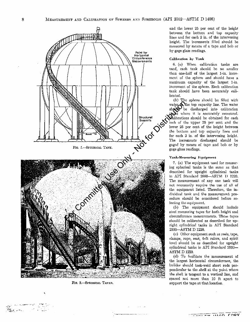
FIG. SPHERICAL TANE.
Structural Supports
/
RQ. 8.aPHEBICAL TANKS.
and the lower 25 per cent of the height between the bottom and top capacity lines and for each 2 in. of the intervening height. The increments filled should be measured by means of a tape and bob or by gage glass readings.
Calibration by Tank U. (a) When calibration tanks are
used, each tank should be no smaller than one-half of the largest 1-in. incre- ment of the sphere and should have a maxiinum capacity of the largest 1-in. increment of the sphere. Each calibration tank should have been accurately cali- brated.
( b ) The sphere should be Med with water to the top capacity line. The water should be discharged into calibration tanks where it is accurately measured. Calibrations should be obtained for each inch of the upper 25 per cent and the lower 25 per cent of the height between the bottom and top capacity lines and for each 2 in. of the intervening height. The increments discharged should be gaged by means of tape and bob or by gage glass readings.
Tank-Measuring Equipment 7. ( u ) The equipment used for measur-
ing spherical tanks is the same as that described for upright cylindrical tanks in M I Standard 2550-ASTM D 1220. The measurement of any one tank will not necessarily require the use of all of the equipment listed. Therefore, the in- dividual tank and the measurement pro- cedure should be considered before se- lecting the equipment.
( b ) The equipment should include steel measuring tapes for both height and circumference measurements. These tapes should be calibrated as described for up- right cylindrical tanks in API Standard 2550-ASTAI D 1220.
(c) Other equipment such as reels, tape, clamps, rope, seat, 6-ft rulers, and spirit level should be as described for upright cylindrical tanks in API Standard 2550- ASTM D 1220.
(d ) To facilitate the measurement of the largest horizontal circumference, the builder should tack-weld short rods per- pendicular to the shell at the point where the shell is tangent to a vertical line, and spaced not more than 10 ft apart to support the tape at that location.
PROBLEM HARD COPY
For Com
mittee U
se O
nly - N
ot for
Dist
ributi
on
STD 2552-65 4 0732270 0067672 'p
MEASUREMEST Ahm CALIBRATIOX O F SPHERES Ahm SPHEROIDS (API 2552-AST31 D 1408) 9
Field Measurements 8. (u) Measure the circumference of the
horizontal great circle a t the equator. The columns supporting a sphere usualllr extend a few inches above the equator; where this occurs step-overs mill be re- quired. It is permissible to make this circumference measurement at a location just above the tops of the columns where the tape path is clear. When this is done, record the measured circumference, C, and the height, H , above the equator a t which G a a s measured.
(b) Measure the circumference of a vertical great circle passing through the poles.
( c ) Measure the circumference of an- other vertical great circle at right angles to the first vertical great circle.
(d ) Measure the total inside height, D, a t the vertical centerline of the sphere.
( e ) There is usually a manhole or other fitting a t this centerline. In this event, measure the vertical inside height, D,, , at a convenient distance, m, from the centerline. Record D, and m for later calculation of the centerline height.
(f) Spherical tanks should be re-cali- brated as a result of the following condi- tions :
(1) When the deadwood is changed, or additional deadwood such as concrete is installed inside the tank. (9) When the tank is repaired or
changed in any manner which may affect the total or incremental volume. (3) When the tank is moved.
Calculations 9. (u) If the field measurement of the
outside circumference [Section 8 (u) ] was made a t a height, H, above the equator to clear the tops of the columns, com- pute the outside circumference, Co, at t.he equator as follows:
Co = dc2 + (27rW ( b ) Correct each outside circumference
to the inside of the shell plates, by sub- tracting 2rt. For t, use the weighted
Definitions
11. (u) A Spheroid is a stationary liq- uid storage tank having a shell of double curvature. Any horizontal cross-section is circular and a vertical cross-section is
average thickness along each tape path. Designate the corrected circumferences Cl, C2, and Ca.
( c ) Compute the total volume as fol- lows :
CI x c2 x c3 6 2
V =
( d ) If the vertical inside height, D,, was measured a t a distance, m, from the centerline of the sphere to a manhole or other fitting [Section 8 (e)], calculate the total inside height, D, a t the centerline as follows:
D = d D m 2 + 4 n ? ( e ) Compute the partial volume a t each
desired incremental depth. A method em- ploying a calculating machine may be set up as follows :
V = total volume of sphere. G = gage increment. A = one-half of the vertical inside
Let:
height.
A - H M = - G
H = gage h-eight to bottom of increment. For the bottom increment:
A M = - G
A ! ! - A!! v m = xi - (7)
For each succeeding increment:
V m = Vm+i + MKz
The volume of each increment above the bottom increment is MR, greater thhan that of the increment directly below.
NOTE 2.-Tables of partial volumes are available but the interpolations required are
PART II. SPHEROIDAL TANKS a series of circular arcs. The height is reduced compared with that of a sphere. The bottom rests directly on a prepared grade. The spheroid has a base plate rest- ing on the grade and projecting beyond
often more laborious than machine calcuia- tion using the foregoing procedure. A sample calculation for a 3û-ft-diameter spherical tank is shoKn in Appendix I.
Effect of Thermal Changes on Spherical Tank Shells 10. (a) The effect of expansion or con-
traction of tanks containing liquids a t normal temperature may be disregarded. Correction for expansion or contraction will not be necessary except under con- ditions of use requiring very accurate re- sults as to the partial or total volumes of heated or refrigerated contents.
( b ) When corrections for temperature effect are required, it is necessary to estimate the service temperature of the contents and compute volume correc- tions due to the difference in temperature from 60 F, the normal calibration tem- perature. Compute the volume correction as follows: Volume correction, per cent = K ( t . - 60) where : K = a coefficient (see Appendix III) . t , = service temperature of tank shell, in
The coefficient, K , is based upon a low-carbon steel having a coefficient of thermal expansion of 0.0000065 per deg F. When the tank is con- structed of a Werent metal, the coef- ficient of expansion shall be calcu- lated in accordance with Appendix III.
( c ) For noninsulated metal tanks, the temperature of the shell may be taken as the mean of the adjacent liquid and ambient air temperatures on the inside and the outside of the shell a t the same location. In applying these principles to both spheres and spheroids, only the horizontal dimensions are functions of tank calibration corrections. The liquid height dimension is a function of gaging the liquid level; accordingly, the effect of thermal expansion or contraction on innage and outage gage readings should be considered separately.
degrees Fahrenheit.
the shell. Structural members rest on the base plate and support the overhanging part of the shell for a short dista.nce above t.he base plate. A drip bar is welded to the shell in a horizontal circle just above the
For Com
mittee U
se O
nly - N
ot for
Dist
ributi
on

10
S T D 2552-65 1 0732290 0067673 b r
MEASURENEXT AND CALIBRATIOK OF SPHERES ASD SPHEROIDS (API 2552-ASTM D 1408)
--
FIG. ~ . - S M O O T H SPHEROIDAL TANK.
FIG. 4.-xODED SPHEROIDAL TANK.
FIG. ~.-NODED SPHEROIDAL TAXE.
structural supports to intercept rain wa- ter.
3, usua.11~ has no inside structural mem- bers to support the shell or roof.
í c ) A Noded Snheroid. shown in Fim.
( b ) A Smooth Spheroid, shown in Fig. members inside the tank.
Outline of Procedure '
12. Practical difficulties prohibit meas- uring a spheroid except a t two locations. One of these is on the shell a t the upper edge of the drip bar; the other is at the largest horizontal circumference where the shell is tangent to a vertical line. At other locations it would be difficult, if not impossible, to support the meas- uring tape. The theoretical horizontal radii are calculated and then adjusted to conform with the measured circumfer- ences.
Liquid Calibration
13. ( a ) Liquid calibration is preferred for any tank or portion of a tank not sus- ceptible to adequate or accurate meas- urement. Because circumferential meas- urements on a spheroid are limited to two, liquid calibration (see BPI Standard 2555-ASTiLI D 1406) is preferred to the measurement procedure.
(b) Adequate facilities are not always available and the measurement procedure is given as a satisfactory alternative for spheroids. When visibly distorted, the spheroid should be liquid calibrated.
( c ) Liquid calibration may be per- formed by meter, using either water or a product of low volatility such as No. 2 fuel oil. If calibration tanks are used, the liquid should be water.
(a) When calibrated by liquid, the spheroid should have been filled a t least once with a liquid a t least as heavy as the liquid to be stored.
( e ) When calibrat.ion tanks are used, they shall be accurately calibrated by the critical measurement procedure (as ont- lined in API Standard 2550-ASThI D 1220), or by the water draw procedure, into National Bureau of Standards stand- ardized measures (as outlined in APZ Standard 1101 : Measurement of Petro- leum Liquid Hydrocarbons by Positive Displacement Meter) ,
(f) When meters are used, they should be installed, operated, and proved accord- ing to the systems outlined in API Stand- ard 1101 (see also API Standard 2555- ASTM D 1406).
(9) Capacity Table.-The capacity table should be prepared in any desired increments (usually % in.) using graphs or mathematical methods to establish a smooth curve.
I PWOBLEH HARD COPY
For Com
mittee U
se O
nly - N
ot for
Dist
ributi
on

S T D 2552-65 I 0732270 0067674 -q 11 A!rEASUREhIENT AND CALIBRATION O F S P H E R E S AND SPHEROIDS (MI 2552-ASTM D 1408)
.Calibration by Meter
14. The spheroid may initially be either empty or fuil. Calibration should pro- ceed by introducing or withdrawing liquid. Meter readings should be taken for each inch of the upper 25 per cent and the lower 25 per cent of the height between the bottom and top capacity lines and for each 2 in. of the intervening height. The increments med should be measured by means of a tape and bob or by gage glass readings. After emptying the spheroid, the elevation of the datum plate relative to the bottom capacity line should be checked.
Calibration by Tank
15. (u) When calibration tanks are used, each tank should be no smaller than one-half of the largest 1-in. increment of the spheroid and should have a maximum capacity of the largest 1-in. increment of the spheroid. Each calibration tank should have been accurately calibrated.
(b ) The spheroid should be ñlled with water to the top capacity line. The water should be discharged into calibration tanks where it is accurately measured. Calibrations should be obtained for each inch of the upper 25 per cent and the lower 25 per cent of the height between the bottom and top capacity lines and for each 2 in. of the intervening height. The increments discharged should be gaged by means of a tape and bob or by gage glass readings. After the water is discharged, the level of t.he datum plate relative to the bottom capacity line should be checked.
Tank-Measuring Equipment
16. (u) The equipment used for meas- uring spheroids is the same as that de- scribed for upright cylindrical tanks in API Standard 255O-ASTM D 1220. The measurement of any one tank mill not re- quire the use of all of the equipment listed. Therefore, the individual tank and the measurement procedure should be considered before selecting the equip- ment.
( b ) The equipment should include steel measuring tapes for both height and circumference measurements. These tapes should be calibrated as described for upright cylindrical tanks in API Standard 2550-ASTM D 1220.
L
(c) Other equipment such a5 reels, tape, clamps, rope, seat, 6-ft rulers, and spirit level should be as described for upright cylindrical tanks in API Standard 2550- ASTM D 1220.
( d ) To facilitate the measurement of the largest horizontal circumference, the builder should tack-weld short rods per- pendicular to the shell a t the point where the shell is tangent to a vertical line and spaced no more than 10 f t apart to sup- port the tape at that location.
Volume Below Bottom Capacity Line
17. (u) The volume below the bottom capacity line is not usually included in the tank capacity. Zero gage or the gage datum should coincide with the level of t.he bottom capacity line. The main cali- bration table should not include any volume below that level.
( b ) In noded spheroids, a circular girder a t the bottom node forms a dam which a t very low levels would permit the product surface or the interface surface of a water bottom to stand at different levels in the bottom troughs. To avoid t.his condition, equalization holes should be provided in the circular girder by the builder, and the bottom capacity line should be above these holes. The eleva- tion below datum of the lowest point a t which the water level will equalize be- tween nodes should be noted on the calibration table.
(c) If a dam plate or weir is used to keep water away from the outlet connec- tion, its elevation relative to the datum should be noted on the calibration table.
( d ) The volume below the bottom capacity line should be noted on the calibration table. It should be marked “approximate,” unless it was obtained by liquid calibration. An audiary table giving incremental volumes below the bottom capacity line may be furnished if required.
Field Measurements
18. (u) Measure the elevation of the datum plate relative to the bottom capac- ity line.
(b ) Measure the elevation of the top of the drip bar at four points equally spaced around the spheroid, relative to the bottom capacity line.
(c) Measure the outside circumference of the spheroid a t the largest horizontal
circumference where the shell is tangent to a vertical line, supporting the tape on the rods provided by the builder.
( d ) Measure the outside circumference of the spheroid on the shell a t the upper edge of the drip bar.
NOTE $.-During the measurements pre- scribed in Paragraphs (c) and (4, the spheroid should be approximately 75 per cent full.
(e) Spheroidal tanks should be re- calibrated as a result of the following conditions :
(1) When the deadwood is changed, or additional deadwood such as concrete is installed inside the tank.
(2) When the trank is repaired or changed in any manner which may affect the total or incremental volume.
(3) When the tank is moved.
Calculations
19. (u) Using dimensions from the builder’s drawings, compute the hori- zontal radius to the inside of the shell a t the midheight of each 1-in. increment of depth above the capacity line.
( b ) Similarly compute the inside hori- zontal radius a t the largest horizontal circle and at the elevation of the top of the drip bar.
(c) Divide the field measurements [Section 18(c) and ( d ) ] by 2 í ~ to get the average outside radius a t each of these locations and subtract the horizontal thicknesses to get the inside radius.
( d ) Adjust all horizontal radii com- puted in Paragraph (u) by multiplying by the inside radius from Paragraph (c) and dividing by the corresponding calcu- lated inside radius from Paragraph ( b ) . Use the drip bar adjustment to an eleva- tion midway between the drip bar and the largest horizontal circumference. Use the largest horizontal circumference adjust- ment for all higher increments.
(e) Using the adjusted radii, compute the volume of each 1-in. increment as- suming that each is a cylinder.
(f) Correct for deadwood. (9) Complete the gage table by totaling
the net incremental volumes, starting with zero a t the bottom capacity line. The gage table may. be prepared in any desired increments (usually ‘/8 in.) using graphs or mathematical methods to establish a smooth curve.
(h) Record on the gage table the ele-
For Com
mittee U
se O
nly - N
ot for
Dist
ributi
on
0732270 0067675 O r S T D 2552-65
12 MEASUREMENT Ahm CALIBRATION OF SPHERES AND SPHEROIDS ( 0 1 2552-ASTM D 1408)
vation of the datum plate with relation NOTE 5.-A sample calculation for a the shell of smooth spheroidal tanks, to the bottom capacity line. 50C~û-bbl spheroidal tank is d o m in AP- causing change in the incrementa.1 01
total tank volumes as a result of Wer- pendix II. notation stating whether it mas pre- Effect of Thermal Changes on Smooth ences in temperature, may be computed pared from data obtained by water Spherical Tank sheus as described for spherical tanks in Section calibration or by the measurement method. 20. The effect of volume changes in 10.
(i) The capacity bble should bear a
For Com
mittee U
se O
nly - N
ot for
Dist
ributi
on

- - - STD 2552-b5 0732290 O067676 q-
APPESDIX I
SAMPLE CALCULATION FOR A 38-FT-DIAMETER SPHERICAL TAXI<
h o a i REPORT OF F I E L D MEASTiREbíENTS : Horizontal circumference, Cl = 119.680 ft Circumference taken in a vertical plane, CP = 119.760 f t Circumference taken 90 deg from Cf in a vertical plane, C3 = 119.740 f t Inside vertical height measured 34 in. off centerline, D, = 37 f t 636 in. Distance C mas taken above equator, H = 10 in.
CORRECTED HORIZONTAL CIRCUhlFEREXCE :
có = za /F = 6.283186 1/(19.01766)2 + (0.8333333)2
Ca = 119.7945 ft
INSIDE CIRCUMFERENCES :
Cl = 119.7945 f t - (0.72 in. X ~ / 6 ) = 119.4175 f t . (Plate thickness = 0.68 in. and 0.76 in.;
C2 = 119.760 f t - (0.8783333 in. X r / G ) = 119.4048 f t CI = 119.740 f t - (0.6783333 in. X r/G) = 119.3848 f t . (Plate thickness = 0.65 in., 0.68 in.,
and 0.72 in.; Weighted average = 0.6783333 in.)
Average = 72 in.)
VERTICAL CEPITERLINE DIANETER:
D = dDm2 + 4mQ = d(37.56250)2 + 4(2.833333)2 = 37.98754 f t
where: m = distance off centerline, in feet. D = vertical diameter at centerline, in feet.
Vo~uam OF SPHERE: Cl X C; X C3 119.4175 X 119.4048 X 119.3848
- = = 28,746.68 CU f t 6 9 59,21764
V =
1728 231 X 42
V = 28,746.68 X ~ = 5120.002 bbl
PARTIAL VOLUMES FOR INCREMENTAL T'ALUES (>d-IN. INCREMENTS) :
V = 5120.002 bbl G = 1 in.
X 12 = 227.9252 in. 37.98754
2 A = - - -
Inside height = 37.98754 f t
where: G = incremental height, in inches. A = one-half vertical height of tank, in inches.
G - = O.CM387404 A
13
For Com
mittee U
se O
nly - N
ot for
Dist
ributi
on

1'4
226'. 9252 225.9252 224.9252 223.9252
. . .
STD 2552-65 0732270 0067677 3~
MEASUREXEST AKD CALIBRATION OF SPHERES ASD SPHEROIDS ( M I 2552-ASTX D 1408)
0.07381* 0.22100 O. 36753 O. 513.12 O. 65866
. . .
(:y = 0.00000008445453
3 - (s)" = 2.999981
K - - 1 - 4" (d> - [3 - ($y] = 16.84753
= 0.0006486110 K z = %(A)
VOLUNE OF BOWOX INCREMENT :
A G
M = - = 227.9252
Vm = 16.84753 - 16.77372 = 0.07381 bbl
VOLUNE OF EACH SUCCEEDING IPICREMENT: v m = v m + i + I M R 2
I incremental Height
O f t 1 in . . . . . . . . . . . . . . . . O f t 2 in . . . . . . . . . . . . . . . . O f t 3 in . . . . . . . . . . . . . . . . O f t 4 in . . . . . . . . . . . . . . . . O f t 5 in . . . . . . . . . . . . . . . .
* Volume of bottom increment included in Z MKz .
APPEi\i?)IX II
Partial Volume
1.83442 . . .
Barrels per W in. (Diff. Vol. i 8)
0.0642 O. 0823
. . .
SAMPLE CALCULATION FOR A 5000-BBL SPHEROIDAL TANK
FROM REPORT OF FIELD MEASUREMENTS:
(u) Datum plate set a t elevation of bottom capacity line. ( b ) Top of drip bar to bottom capacity line:
( I ) 5 f t 8% in. (2) 5 f t 9 in. (S) 5 f t 9 in. (4) 5 f t 936 in. Average = 5 f t 9 in. (checks with blueprint).
(c) Maximum horizontal circumference = 129.680 f t . (d ) Circumference a t drip bar = 118.330 it.
CALCULATIONS :
Inside radius at maximum circumference = 129.680 f 2a - 0.0225 ft- (plate)
Inside radius at maximum circumference (from blueprint) = 20.6oô80 f t = 20.61671 f t
Multiplier for adjusting radii in upper portion of tank = 2oG1671 - - 1.000481 20.60680
Inside radius a t drip bar = (118.330 + 2n) - (horizontal thickness of plate) = 18.83280 - 0.03222 = 18.80058 f t
175.1425 O33 149.5008 12
Horizontal thickness of plate = - X = 0.03222 f t
For Com
mittee U
se O
nly - N
ot for
Dist
ributi
on

S T D 2552-65
150.8981 in. 152.9748 in. 154.9843 in.
0732290 0067678 5 r
O. O023 0.9194 7.3552 14.9144
O. 9217 O . 9449 O . O023
22. G736 O . 9472
O. 9699 O. 9722 0.0023
15 aIEASUREMENT AND CALIBRATION O F SPHERES AND SPHEROIDS ( M I 2552-ASTA4 D 1408)
where: 175.1425 = outside radius of vertical curvature, in inches. 149.5008 = horizontal distance from drip bar t.0 center of radius of vertical curvature,
in inches. 0.33 = p1at.e thickness a t drip bar, in inches.
Inside radius a t drip bar (from blueprint) = 18.78130 f t
Multiplier for adjusting radii in lower portion of tank = 18.80058 = 1.001027
. - ’
18.78130
EXAMPLE OF RUN SHEET (PARTIAL)
Horizontal IncrementalHeight I h 1 a 1 R 1 1 .
I I I I I I
. . . . 1 . . . . I . . . . I . ... I . . . . I . . . . _ I . . . .
I I
De$g’!;.bbl Net, bbl per % in. Total, bbl Horizontal Radius X Gross bbl Applicable Radius per d in.
Multiplier (O.WoM0.17610 R ) I I I I
I . . ’ ’ . . . . I . . . . I . . . . I _ . . . .
where (see Fig. 6 ) : h = vertical distance from center of segment to bottom capacity line. a = vertical distance from center of segment to center of radius of vertical curvature. R = radius of vertical curvature. L = horizontal distance from centerline of tank to center of radius of vertical curvature.
For Com
mittee U
se O
nly - N
ot for
Dist
ributi
on

16
STD 2552-65 0732290 0067677 7 r MEASURENEXT fim CALIBRATIOX OF SPHERES AND SPHEROIDS ( M I 2552-ASTM D 1408)
APPENDIX III
PROCEDURE FOR COMPUTING THE VOLUME CORRECTION FOR THERMAL EX- PANSION OR CONTRACTION OF SPHERICAL AND SMOOTH SPHEROIDAL TANKS
Value of H/D
FIQ. VOL^ CORRECTION COEFFICIENT FOR THERMAL EXPANSION OR CONTRACTION OB SPHERICAL AND SMOOTH SPHEROIDAL TANKS CONSTRUCTED OF LOW-CARBON STEEL.
For Com
mittee U
se O
nly - N
ot for
Dist
ributi
on

S T D 2552-65 1 - - 0 7 3 2 2 9 0 0 ~ -
MEASUREMEXT AKD CALIBRATIOX OF SPHERES AND SPHEROIDS (API 2552-ASTM D 1408) 17
The basis and method of correcting the volume of spherical and smooth spheroidal tanks which have been affected by changes in temperature is described in Section 10. The coefficient, KI, is obtained from the curve shown in Fig. 7 which is based on a mean thermal expansion co- efficient, ant, of 0.0000065 per deg F. The value, KI, taken from the curve must be adjusted to the actual thermal expansion, m, of the tank material a t the actual tank temperature, t . For low-carbon steel and structural aluminum the values of am are:
Tank Shell Temperature, 1, OF
SteeI -70 t o -21 -20 to +28 +29 t o 78 79 to 128 129 to 177 178 t o 227 228 to 276 277 t o 326 327 t o 376 377 to 425
-70 to -11 -10 to +49 4-50 t o 109 110 t o 169 170 to 229 230 t o 289 290 to 349 350 to 409
Aluminum
Value of Q ~ Z per "F
0.0000060 0.0000061 0.0000062 0.0000063 0.0000064 0.0000065 0.0000066 0.0000067 0.0000068 0,0000069
o.oooo122 o. oooo124 O. oooO126 O.ooOo128 O.oooO130
O.oooO134 O.ooOo136
The value of K for use in Section 10 is equal t o Ki from the curve shown in Fig. 7, divided by 0.0000065 per deg F and multiplied by the proper value of am for the tank shell material and temperat.ure; that is:
where: cum = the mean coefficient of linear expansion between temperatures, t , and 60 F.
4M-Sept. 1966
\
For Com
mittee U
se O
nly - N
ot for
Dist
ributi
on