for-document - request recommendation use lng as fuel ... · pdf filehazid hazid report report...
TRANSCRIPT

Proposed text of a derogation for the motor tank vessel “Argos GL” regarding the use of LNG for propulsion
Transmitted by the Government of the Netherlands
Attached is the proposed text of a possible derogation for a vessel regarding the use of LNG for propulsion.
INF.4Economic Commission for Europe
Inland Transport Committee
Working Party on the Transport of Dangerous Goods
Joint Meeting of Experts on the Regulations annexed to the European Agreement concerning the International Carriage of Dangerous Goods by Inland Waterways (ADN)
Twenty-seventh session Geneva, 24-28 August 2015 Agenda item 3 (b) Implementation of the ADN: Special authorizations, derogations and equivalents
English
29 May 2015

INF.4
2
Decision of the ADN Administrative Committee relating to the motor tank vessel “Argos GL”
Derogation No. x/2015 of 28 August 2015
The competent authority of the Netherlands is authorized to issue a trial certificate of approval to the motor tank vessel ‘Argos-GL’, European Number of Identification (ENI) to be determined, for the use of liquefied natural gas (LNG) as fuel for the propulsion installation.
Pursuant to paragraph 1.5.3.2 of the Regulations annexed to ADN, the above-mentioned vessel may deviate from the requirements of 7.1.3.31 and 9.1.0.31.1 until 30 June 2019. The Administrative Committee has decided that the use of LNG is sufficiently safe if the following conditions are met at all times:
1. The vessel has a valid ship’s certificate according to the Rhine Vessel Inspection Regulations, based on recommendation 19/2014 dated 9 September 2014 of the CCNR.
2. A HAZID study by the recognized classification society (Annex 1) shows that the safety level of the LNG propulsion system is sufficient. This study covered, but was not limited to, the following issues:
- Interaction between the cargo and LNG; - Effect of LNG spillage on the construction; - Effect of cargo fire on the LNG installation; - Different types of hazard posed by using LNG and diesel as fuel; - Adequate safety distance during bunkering operations.
3. The information that LNG is used as fuel is included in the dangerous goods report to traffic management and in emergency notifications;
4. All data related to the use of the LNG propulsion system shall be collected by the carrier. The data shall be sent to the competent authority on request;
5. An annual evaluation report shall be sent to the UNECE secretariat for information of the Administrative Committee. The evaluation report shall contain at least information on the following:
(a) system failures;
(b) leakages;
(c) bunkering data (LNG);
(d) pressure data;
(e) abnormalities, repairs and modifications of the LNG system including the tank;
(f) operational data;
(g) inspection report by the classification society which classed the vessel.
Attached documents:
- Annex 1: HAZID Study - Annex 2: Deviations from IGF Code - Annex 3: Project description - Annex 4: Bunkering procedure - Annex 5: Crew Training - Annex 6: Third party verification DNV-GL - Annex 7: CCNR Recommendations

Annex 1 to RV (14) 59 = RV/G (14) 92 = JWG (14) 86
Working together for a safer world
Report no: 50102448 R01 Rev: 00
Date: 29 April 2014
Argos Bunkering LNG Fuel System HAZID HAZID Report
Report for: Lloyd's Register EMEA

Report no: 50102448 R01 Rev: 00 Page i
Date: 29 April 2014 ©Lloyd’s Register 2014
Summary
Argos Bunkering LNG Fuel System HAZID
HAZID Report
Security classification of this report: Distribute only after client's acceptance
Report no:
50102448 R01
Revision:
00
Report date:
29 April 2014
Prepared by:
Afshan Hussain Consultant __________________________
Reviewed by:
Chris Swift Principal Consultant __________________________
Approved by:
Dr Andrew Franks Managing Director __________________________
Entity name and address:
Lloyd's Register Consulting - Energy Limited
Regus Manchester Business Park
3000 Aviator Way
Manchester
M22 5TG
United Kingdom
Client name and address:
Lloyd's Register EMEA
K.P. van der Mandelelaan 41-A
Rotterdam
3062 MB
The Netherlands
Our contact:
Chris Swift
T: +44 (0) 7917 088169
Client contact:
Bas Joorman
T: +31 (0)6 53600397
Lloyd’s Register Group Limited, its subsidiaries and affiliates and their respective officers, employees or agents are, individually and collectively, referred to in this clause as ‘Lloyd’s Register’. Lloyd’s Register assumes no responsibility and shall not be liable to any person for any loss, damage or expense caused by reliance on the information or advice in this document or howsoever provided, unless that person has signed a contract with the relevant Lloyd’s Register entity for the provision of this information or advice and in that case any responsibility or liability is exclusively on the terms and conditions set out in that contract. Except as permitted under current legislation no part of this work may be photocopied, stored in a retrieval system, published, performed in public, adapted, broadcast, transmitted, recorded or reproduced in any form or by any means, without the prior permission of the copyright owner. Enquiries should be addressed to Lloyd’s Register, 71 Fenchurch Street, London, EC3M 4BS. ©Lloyd’s Register 2014.

Report no: 50102448 R01 Rev: 00 Page ii
Date: 29 April 2014 ©Lloyd’s Register 2014
Document history
Revision Date Description/changes Changes made by
00 29/04/2014 HAZID Report
Glossary/abbreviations
FSRU Floating Storage and Regasification Unit
HAZID Hazard Identification
HAZOP Hazard and Operability
IOSH Institution of Occupational Health and Safety
ISO International Standards Association
HP High Pressure
LNG Liquefied Natural Gas
LOPA Layer of Protection Analysis
LP Low Pressure
LPG Liquefied petroleum Gas
LR Lloyd’s Register Group
N2 Nitrogen
NG Natural Gas
P&ID Piping and Instrumentation Diagram
PBU Pressure Build Up
QRA Quantitative Risk Assessment
SME Subject Matter Expert
ToR Terms of Reference

Report no: 50102448 R01 Rev: 00 Page iii
Date: 29 April 2014 ©Lloyd’s Register 2014
Table of contents Page
1 Introduction ..................................................................................................................................... 1
2 Design Details ................................................................................................................................ 1
2.1 LNG Fuel Supply System ..................................................................................................... 2
2.2 LNG Storage Tank and Cold Box ........................................................................................ 2
2.3 Tank Room ........................................................................................................................... 2
2.4 Vaporizer .............................................................................................................................. 2
2.5 PBU (Pressure Build-up Unit) .............................................................................................. 2
3 HAZID ............................................................................................................................................. 3
3.1 HAZID Objectives................................................................................................................. 3
3.2 Study Team and Attendance ............................................................................................... 3
3.3 Study Methodology .............................................................................................................. 9
3.4 Risk Rating .........................................................................................................................11
3.5 HAZID Study Results .........................................................................................................12
3.5.1 HAZID Meeting ................................................................................................................ 12
3.5.2 Study Preparation and References ................................................................................. 12
3.5.3 Study Nodes .................................................................................................................... 12
3.5.4 Study Minutes ................................................................................................................. 13
3.5.5 Main HAZID Issues ......................................................................................................... 13
3.5.6 Items for Further Consideration ....................................................................................... 14
3.5.7 Consequence Assessment and Risk Assessment Results ............................................. 14
3.5.8 Overall HAZID Assumptions............................................................................................ 15
4 Conclusions ..................................................................................................................................16
Appendix A – HAZID Minutes Appendix B – HAZID P&I Diagrams

Report no: 50102448 R01 Rev: 00 Page 1
Date: 29 April 2014 ©Lloyd’s Register 2014
1 Introduction
ARGOS is proposing an LNG fuelled Bunkering vessel which uses Liquefied Natural Gas
(LNG) as the primary fuel, with a fuel oil powered engine as backup. The proposed design is
at an early stage and has the following overall features:
Single LNG storage tank located below deck;
The Pressure Build-up Unit and Vaporiser;
Fuel supply (Natural Gas) to the engines;
Cold box Ventilation System; and,
Engine Room Ventilation System.
To help manage safety risks a HAZID of the proposed design has been undertaken. The
principal objective of the HAZID is to increase confidence that safety related aspects of the
design are appropriate. Further objectives are covered in Section 3 and detailed in the Terms
of Reference (ToR); Lloyd’s Register Consulting Document No 50102448 TN01 Rev 00.
2 Design Details
Details of the proposed design are shown in the reference documents listed in Table 2.1.
Table 2.1 – Reference Documents
Document Title Document Reference and Date
Issued By
Piping and Instrumentation Diagram – LNG Fuel system – Page TB01
1406-1100-100, 17-03-2014 Cryonorm Systems
Piping and Instrumentation Diagram – LNG Fuel system – Page TC01
1406-1100-100, 17-03-2014 Cryonorm Systems
Piping and Instrumentation Diagram – LNG Fuel system – Page TD01
1406-1100-100 Rev. 1, 17-03-2014
Cryonorm Systems
LNG & Fuel Oil Bunker T – mts "ARGO GL" Hazard Area Plan
201-18 Drawing no.10 31.12.2013
Rommerts Ship Design
LNG Bunkering Development in Europe
Argos LNG bunkership project CCNR feb 2014.pdf
Argos
Safety Diagram Safety Diagram.pdf -
Argos Gas Engine Ventilation Calculations
Argos gas engine ventilation calculations.pdf
Argos
These documents were made available to the study attendees prior to the study and were
provided as hard copies during the study.
The process design, based on details in the reference documents, is summarised below.

Report no: 50102448 R01 Rev: 00 Page 2
Date: 29 April 2014 ©Lloyd’s Register 2014
2.1 LNG Fuel Supply System
The main features of the LNG fuel system are:
A single LNG storage tank with cold box fitted immediately adjacent to the tank, both installed in a separate tank room;
The cold box is an enclosed space with ventilation that extracts air from the tank room, passes it through the cold box and discharges to a vent stack;
A separate ventilation system for the tank room;
A fuel supply system to three 3 MWM LNG generator sets; and,
A back-up diesel driven generator installed in a separate engine room.
2.2 LNG Storage Tank and Cold Box
The LNG storage tank is a vacuum insulated pressure vessel with double walls. 'Super
insulation' fills the space between the two walls. The inner vessel is constructed from
austenitic-stainless steel. The vessel is fitted with internal baffles. The outer vessel is
designed as secondary containment with a vent through a drop-off disk into the cold box.
2.3 Tank Room
The Tank Room is attached to the lower section of the storage tank and contains the LNG
storage tank, vaporizer (including PBU), all LNG connections and valves. This space is
monitored to detect gas leakage using gas detectors. It is currently proposed to provide the
room with a mechanical forced ventilation system with a capacity of at least 30 air changes
per hour.
2.4 Vaporizer
The function of the vaporizer is to convert LNG into natural gas for engine use. Heat is
supplied from the engine cooling system. A closed loop water/glycol system is used as the
heat transfer medium in a secondary loop the vaporizer shell (glycol/water) is made of
austenitic-stainless steel and the tubes in the vaporizer and PBU are made of austenitic-
stainless steel 316.
2.5 PBU (Pressure Build-up Unit)
The pressure build up unit is used to provide pressure in the LNG storage tank, in order to
supply LNG to the vaporizer. The PBU and vaporizer form a single combined unit, located in
the tank room.

Report no: 50102448 R01 Rev: 00 Page 3
Date: 29 April 2014 ©Lloyd’s Register 2014
3 HAZID
3.1 HAZID Objectives
The objectives of the HAZID were to identify:
1. Hazards and how they can be realised (i.e. the accident scenarios – What can go wrong and how?);
2. The consequences that may result;
3. Existing measures/safeguards that minimise leaks, ignition and potential consequences, and maximise spill containment; and
4. Recommendations to eliminate or minimise safety risks.
3.2 Study Team and Attendance
The study was facilitated by Mr Chris Swift from Lloyd’s Register Consulting over two days on
April 15th and 16
th 2014. The HAZID Study team consisted of a range of Subject Matter
Experts (SMEs) with knowledge and experience of the design. Team members, a summary of
their qualifications, experience and attendance at each node of the study are detailed in Table
3.1 and Table 3.2 below and in the HAZID minutes in Appendix A.
Mr Swift is a Principal Consultant with Lloyd’s Register Consulting Mr Swift, and Lloyd’s
Register Consulting, is independent and has no vested interest in the outcome of the HAZID.
Having an independent facilitator is very important as it allows the facilitator to take an
objective, unbiased view.
An essential role of the HAZID facilitator is to ensure that the HAZID methodology is used
effectively and productively and the facilitator needs to have a deep understanding and
considerable experience in the technique plus technical competence.
Mr Swift is a Chartered Chemical Engineer with a Master’s Degree in Process Safety and
Loss Prevention, with training and experience in a variety of safety study techniques such as
HAZID. Relevant training includes:
Guide Word Approach to HAZOP, IBC, 1993
Safety Study Guarantor Training, Rhodia, 1996
Layer of Protection Analysis (LOPA), IChemE, 2009
Mr Swift has been a Consultant with Lloyd’s Register Consulting for five years and during this
time has facilitated a number of HAZID studies that have provided experience in marine and
flammable gas systems, these include:
HAZID of a diesel/LPG fuelled tanker (2102).
Conceptual phase HAZID of options for use of a modular nuclear reactor for vessel propulsion (2012).
Conceptual phase HAZID for an oil rig decommissioning vessel (2012).
HAZID, spill size evaluation and frequency assessment for increased tanker/jetty operations (2012).
HAZID and assessment of risks of jetty modifications (2012).
Conceptual phase HAZID and ENVID of carbon capture plant (2012).
HAZID of alternate ship propulsion systems (2011).

Report no: 50102448 R01 Rev: 00 Page 4
Date: 29 April 2014 ©Lloyd’s Register 2014
HAZID of options for ballast water treatment systems (2011).
QRA of an onshore LNG regasification terminal (2011)
Risk assessment of onshore gas processing facility and pipeline (2011).
QRA of offshore FSRU/LNG carriers (2011).
Risk assessment of offshore FSRU/LNG terminal. (2011).
HAZID, spill size evaluation and frequency assessment of tanker transfer operations (2009).
Prior to joining Lloyd’s Register Consulting Mr Swift was an Engineer and Process Safety
Engineer, working for a multinational chemical producer. During 22 years of working for this
company Mr Swift gained experience in both the design and operation of a range of
processes, including high pressure flammable systems. Mr Swift has extensive experience in
safety study techniques such as HAZID and attended his first study in 1985. As a Process
Safety Engineer Chris has facilitated over 100 studies over a 15 year period.

Report no: 50102448 R01 Rev: 00 Page 5
Date: 29 April 2014 ©Lloyd’s Register 2014
Table 3.1 - HAZID Team Members
First Name
Last Name
Company Position Professional Qualifications
Experience E-Mail Address
Chris Swift Lloyd's Register Consulting
Principal Safety Consultant, HAZID Study Chair
BSc (Hons) Chemical Engineering MSc Process Safety & Loss Prevention MIChemE, CEng, Grad IOSH"
Process design and assessment of safety on operational sites (22 years). Safety Consultant (5 years). Safety Study Chair experience (18 years).
Afshan Hussain Lloyd's Register Consulting
Safety Consultant, HAZID Study Scribe
BEng (Hons) Chemical Engineering
Safety consultant in the Oil and Gas industry. Experienced study scribe.
Bas Joormann Lloyd's Register EMEA
Principal Specialist IWW
BSc Naval Architecture
25 years’ experience, mainly on Statutory Issues.
Matthijs Breel Lloyd's Register EMEA
Senior Specialist Machinery Systems
BEng (Hons) Mechanical Engineering
25 years’ experience in Engines.
Liviu Porumb Lloyd's Register EMEA
Senior Specialist Electro technical Systems
MSc Electrical Engineering
6 years plan approval and field surveys for LR. 4 year design and commissioning electrical systems for ships.
Leendert
Korvink Flag State (NSI)
Observer BEng (Hons) Mechanical Engineering
> 15 years’ experience in shipping.

Report no: 50102448 R01 Rev: 00 Page 6
Date: 29 April 2014 ©Lloyd’s Register 2014
First Name
Last Name
Company Position Professional Qualifications
Experience E-Mail Address
Peter Petersen DNV GL Observer BSc Civil Engineering
25 years’ experience in (petro) chemical and offshore industry. Involved in Risk Based Inspection studies, services in the area of Asset Operations/Mechanical Integrity, preparation of Safety Reports, QRA's and risk management audits and technical integrity audits. More than 10 years’ experience with performance of risk identification studies (HAZID/HAZOP/What-If), SIL/LOPA-studies, both as leader and as scribe.
Jim Kriebel MWM Benlux
Sales/Project Engineer
Electrical Engineering
+15 years’ experience in Gas Engine Sales.
Stefan Kuijs Cryonorm Projects B.V.
Project Engineer/Project Manager
BSc Mechanical Engineering
4 years’ experience - Engineering, design, construction-, installation, commissioning and start-up of several Cryogenic systems.
Daniel Tabbers Windex Engineering
BV Ventilation Construction Engineer
2 years in HVAC Systems. [email protected]
Ubbo Rommerts Rommerts Ship Design
Naval Architect/Technical Manager
Ship Design 15 years’ experience working in Ship building environment which includes technical/financial design,

Report no: 50102448 R01 Rev: 00 Page 7
Date: 29 April 2014 ©Lloyd’s Register 2014
First Name
Last Name
Company Position Professional Qualifications
Experience E-Mail Address
building and inspections.
Claudia van Batenburg
Raster Technical Account Manager
BSc Electrical Engineering
More than 10 years’ experience in engineering, project management and technical account management in the field of industrial automation in the (Petro) chemical plants, both on and offshore.
Claudia is involved in projects executed according Safety standards IEC 61508/61511 and projects containing SIL Classification and Verification. In her work she is regularly engaged in several safety meetings.
Jereon van Tilborg
D&A Electric
Managing Director
Designer 24 years’ experience in ship electrics.
Piet van den Ouden
ARGOS Project Manager BSc Process and Safety Automation
Project Management and Business Economics
Over 25 years in offshore and onshore oil and gas industry, including work on a chemical plant, implementing SIL safety Standards.
Member of the Dutch NEN PGS 33 workgroup to making safety standards for LNG filling stations.

Report no: 50102448 R01 Rev: 00 Page 8
Date: 29 April 2014 ©Lloyd’s Register 2014
Table 3.2 – Node attendance
First Name Last Name
Node attendance
1.1 LNG Storage Tank
1.2 PBU and Vaporiser
1.3 Gas supply to Engines and the Engines
1.4 Cold Box Ventilation System
1.5 Engine Room Ventilation System
Chris Swift Present Present Present Present Present
Afshan Hussain Present Present Present Present Present
Bas Joormann Present Present Present Present Present
Matthijs Breel Present Present Present Present Present
Liviu Porumb Present Present Present Present Present
Leendert Korvink Partial Partial Absent Absent Present
Peter Petersen Present Partial Present Present Absent
Jim Kriebel Present Not Required Present Not Required Not Required
Stefan Kuijs Present Present Present Present Present
Daniel Tabbers Present Present Present Present Present
Ubbo Rommerts Present Present Present Present Present
Claudia van Batenburg Present Present Present Present Present
Jereon van Tilborg Present Present Present Present Present
Piet van den Ouden Present Partial Present Absent Present

Report no: 50102448 R01 Rev: 00 Page 9
Date: 29 April 2014 ©Lloyd’s Register 2014
3.3 Study Methodology
The approach taken for the study was based on Lloyd’s Register Consulting experience, and
guidance from the following sources on the requirements and best practice for conducting
studies:
HAZOP, Guide to Best Practice, 2nd Edition. IChemE (2008)
BS ISO 31000: 2009, Risk Management – Principles and Guidelines
BS ISO 31010: 2010, Risk Management – Risk Assessment Techniques
The two BS ISO Standards provide useful information on the overall techniques for hazard
identification and risk assessment. The IChemE publication provides specific guidance and
while this is primarily aimed at Hazard and Operability (HAZOP) studies, which are a more
detailed form of HAZID, the guidance provided is useful to the methodology employed for this
HAZID. For example, both types of studies are team based with a facilitator and the
approaches used for study arrangements and reporting are similar. The publication
recognises that the HAZID conducted for this study is an approach that is often undertaken
early in the process design.
The HAZID technique adopted for this study is a checklist based approach used for identifying
scenarios that may lead to releases of material or hazardous events. The technique involves
the definition of discrete process sections, termed “Nodes”, and the application of a checklist
to these Nodes to identify deviations that may lead to a safety or operational problem
(Scenario).
For each Node a checklist of possible hazards is used to identify possible scenarios. A study
checklist, consisting of a list of HAZID prompts, was developed prior to undertaking the HAZID,
as shown in Table 3.3. These prompts were based on previous experience and indicate the
types of hazards that were thought to be applicable to the types of treatment systems being
considered. The list is not exhaustive and the HAZID was not limited to these prompts.
For each item in the list of prompts the team considered realistic scenarios that could lead to
an accident and identified possible causes and outcomes from the accident. After evaluating
the potential consequences of accident scenarios, measures that would be expected to be in
place for prevention, control and mitigation were identified. If these were thought to be
inadequate or insufficient information was available, items for further consideration were
raised.
Minutes of the review were recorded in the PHA-Pro 8 software package by the study Scribe
and are shown in Appendix A. During the meetings the minutes were projected onto a screen.
This allowed team members to comment on the minutes.
Table 3.3 - HAZID Prompts
1. Equipment
1.1 Equipment - failures Could equipment failure be hazardous? e.g. loss of function,
collapse, disintegration, component failure, incorrect
construction materials, overloading, operation outside of
design, release of flammable materials, generation of ignition
sources, rotating seals?
1.2 Control System failures If the control system (total or part) failed what would happen?
1.3 Electrical system failures Are there electrical hazards with the equipment being used?

Report no: 50102448 R01 Rev: 00 Page 10
Date: 29 April 2014 ©Lloyd’s Register 2014
Are electrical supplies present in the area? (Possible damage
to electrical systems).
1.4 Utility failures If utilities were lost (power, air etc.) would this lead to a
dangerous situation?
2. Materials
2.1 Flammable/Oxidising
materials
Are flammable or oxidising materials present or could they be
released in error? Vapour, liquid, solid, residues, chemical
reaction?
2.2 Toxic/asphyxiant
materials
Are toxic/asphyxiant materials present or could they be
released in error? Vapour, liquid, solid, residues, chemical
reaction. Including Eco toxic materials?
2.3 Corrosive materials Are toxic materials present or could they be released in error?
Vapour, liquid, solid, residues, chemical reaction?
2.4 Inerts Are inert materials present (N2, CO2 etc.) or could they be
released in error? Asphyxiation hazards?
2.5 Water Is water present or could it be released in error? Could it
deem Hazardous?
3. Operating Parameters
3.1 Temperature
Are temperatures very high or low, above boiling point, flash
point or auto ignition point? Can decomposition occur? Burns
to personnel, damage to equipment? Ice formation.
Solidification of materials?
3.2 Pressure High pressure or vacuum – effects of leaks. HP/LP interfaces
3.3 Flow High, low or reverse flows?
3.4 Level High or low levels – can tanks be overfilled or run dry?
4. Location/Environment
4.1 Location Hazards
Are there hazards associated with the work location? e.g.
slips, trips, falls, working at height, difficult access, confined
spaces, working over water etc.
4.2 Other activities Would any other activities be taking place in the area? Could
they present a hazard or could this activity affect the other
activities?
4.3 Ambient Conditions Could extremes in ambient conditions or weather be a
problem?

Report no: 50102448 R01 Rev: 00 Page 11
Date: 29 April 2014 ©Lloyd’s Register 2014
5. Operating Modes
5.1 Operation on inland water
ways
Are there any hazards associated with operating on inland
water ways using the technology? i.e. operation alongside, in
emergency or blackout conditions.
5.2 Other Operations Are there any hazards while the ship is docked or undergoing
inspection, maintenance, commissioning or decommissioning?
The Terms of Reference (Lloyd’s Register Consulting Document No: 50102448 TN01 Rev 00)
was circulated to team members prior to the HAZID to provide additional details of the HAZID
approach taken.
3.4 Risk Rating
Risks identified during the HAZID were rated in accordance with a risk matrix provided by
Lloyd’s Register Consulting as shown in the Figure below. This matrix is based on Lloyd’s
Register Consulting experience in using and developing matrices on behalf of operators in the
oil and gas industries. An assessment of risk both before and after considering safeguards
was undertaken. This is a typical approach taken during risk assessments and is beneficial
as it allows the identification of scenarios that have the highest potential for harm and
provides a ‘measure’ of the effectiveness of additional safeguards.
Figure 1: Risk Matrix
It should be noted that the risk ranking is only based on the assessment of risk to personnel
and that low severity consequences that could result in minor injury have been excluded from
the assessment. This approach helps to ensure that the study team only concentrate on
significant risks; which is considered to be an appropriate approach for a HAZID at this stage
of design.

Report no: 50102448 R01 Rev: 00 Page 12
Date: 29 April 2014 ©Lloyd’s Register 2014
3.5 HAZID Study Results
3.5.1 HAZID Meeting
The HAZID meeting was undertaken between 15th and 16
th April 2014 in Room 5.5 at the
Business Centre Netherlands (BCN), Barbizonlaan 25, 2908 MB Capelle a/d Ijssel, Rotterdam,
The Netherlands.
The meeting room was adequately sized for the number of team members and was provided
with the required equipment for undertaking the HAZID. Breaks for refreshments and Lunch
were provided throughout the meetings.
3.5.2 Study Preparation and References
Prior to commencing the Study a Terms of Reference (ToR), Lloyd’s Register Consulting
Document No: 50102448 TN01 Rev 00, was produced by Lloyd’s Register Consulting and
issued to each of the team members. The ToR provided details of the HAZID approach, study
schedule, team members, properties of LNG and reference to some incidents that have
involved releases of LNG.
Team members were also supplied with the reference documents listed in Table 2.1 –
Reference Documents prior to the study.
At the start of the meeting short introductory presentations were given to the study team by
the Project Manager of Argos Energies and Lloyd’s Register Consulting, providing an
overview of the project and HAZID technique, respectively.
3.5.3 Study Nodes
The fuel system was split into the Nodes listed in Table 3.4 for the study. Prior to considering
each node a brief overview of the equipment and its operation was given. This ensured that
the team were fully aware of the extent of the Node and its function.
Table 3.4 - Nodes
Node Description
Study Details
Session Date Start
Time
Finish
Time
Duration
(Minutes)
1.1. LNG Storage
Tank 1 15/04/2014 9.10am 2.30pm 275
1.2. PBU and
Vaporiser 4 16/04/2014 11.00am 2.30pm 165
1.3. Gas Supply to
Engines and
the Engines
2 15/04/2014 2.45pm 5.10pm 145
1.4.
Cold Box
Ventilation
System
3 16/04/2014 9.05am 11.00am 115
1.5. Engine Room
Ventilation
System
5 16/04/2014 2.35pm 3.35pm 60

Report no: 50102448 R01 Rev: 00 Page 13
Date: 29 April 2014 ©Lloyd’s Register 2014
Node 1.5 also detailed the Engine Room Ventilation System. It should be noted that very little
information was available for the design of this system.
The approximate time spent studying each Node is shown in Table 3.4 and the HAZID
minutes in Appendix A. Times include breaks for refreshments but not the lunch breaks. Node
1.1 (LNG Storage Tank) was the most complicated node and took the longest time to study.
Details of team attendance during each day of the study are shown in the HAZID Minutes in
Appendix A and Table 3.1. Notable absences during the study, and Nodes reviewed at the
time of absence were:
15th April 2014
Leendert Korvink (ILT) was not present during the afternoon session (part of Node 1.1
and fully for Node 1.3).
16th April 2014
Piet van den Ouden (Argos) was not present for approximately 1.5 hours (Part of
Node 1.4).
Leendert Korvink (ILT) was not present during the morning session (part of Node 1.2
and fully for Node 1.4).
Jim Kriebel (MWM Benelux) was not available all day (Nodes 1.4, 1.2 and 1.5).
Peter Petersen (DNV GL) was not present during the afternoon session (Part of Node
1.2 and fully for Node 1.5).
None of the absences are judged to have reduced the overall competence of the team.
Note that the order selection of nodes for each day of the study was based on the availability
of personnel. e.g. the node detailing the gas supply to the engines was considered on day one
when Jim Kriebel (MWM Benelux) was available.
3.5.4 Study Minutes
On completion of the HAZID the study minutes were spell checked and proof read. Changes
to spelling or grammar have not been specifically identified. The study minutes are shown in
Appendix A. It is recognised that it is important that the context of the minutes are not
changed during checking and a copy of the study minutes in unchecked format has been
retained and can be made available if required.
3.5.5 Main HAZID Issues
The main issues identified during the HAZID are as follows:
Failure of the pressure control valve 5150NG – Could lead to the gas supply to the engines which can lead to surges of gas or slightly high pressure to the downstream system, possibly up to 10 barg to PCV5182NG. This can lead to damage to the downstream system, possibly up to the engine inlet as it is not rated for 10 barg. Also, failure of this PCV can lead to release of Natural gas onto the engine.
Gas Supply Control system failure - Control system failure can lead to pressure control valves being too far open. This can lead to over pressurization of the downstream gas systems and subsequent release of natural gas
Lesser concerns identified during the HAZID, which could be improved:
Overfilling of the LNG tank – an overfill of the tank due to human error, bunkering or level instrumentation failure can lead to possible over pressurization of the tank leading to failure if the bunkering pressure is high.

Report no: 50102448 R01 Rev: 00 Page 14
Date: 29 April 2014 ©Lloyd’s Register 2014
Loss of tank vacuum – Failure of the outer tank/insulation degradation can lead to loss of insulation leading to heat transfer into the inner tank, leading to vaporisation in the tank, pressure increase and possible overpressure of the tank leading to rupture
Piping leakage associated with the LNG tank - Small releases of NG or LNG into the tank room, could cause possible fire/explosion if ignited. Also possible brittle fracture of the deck if exposed to LNG.
Natural Gas present in the tank room - Possible asphyxiation of personnel if NG concentration is too high.
Vessel impact - Container dropped onto the vessel during bunkering can cause possible damage to the LNG tank leading to fire/explosion.
Overheating due to external fire – Can lead to escalation of loss of containment of the LNG system.
Tube leak in heat exchanger E-5150 – leads to a LNG release into the shell of the heat exchanger. Rapid vaporisation leads to pressure into the water/glycol system which can cause possible rupture of the water/glycol system if the system is over pressurized.
Pump failure leading to loss of circulation around the closed loop system - No flow of water/glycol around the closed loop system, reduces vaporisation capacity leading to possible carry-over of LNG into the NG feed. This can lead to possible failure of the gas supply line to the engine due to low temperatures.
Control System failure leads to high flow to the PBU through valve 5130 - Pressure increase in the storage tank can lead to possible rupture, leakage of the tank or possible over pressurization in the tank room.
Control System Failure in the gas line after PCV5150NG - High flow of LNG through the vaporiser as the downstream system is de pressurised can lead to possible carry through of LNG if the vaporiser capacity is exceeded leading to LNG release from the gas piping system.
Leak from the LNG piping system into the cold box - due to fatigue/weld failure, LNG can be released into the cold box which will collect in the base of the box and form a liquid level. LNG will also vaporise to form NG which will be vented through the cold box extraction system to the vent stack. If the extraction system is not sufficient for the leak size gas will be released into the tank room leading to the possibility of over pressurization of the tank room and fire/explosion if ignited.
NG release into the engine room from the NG fuel supply - Release of NG into the engine room which is not rated for explosive atmospheres. Possible explosion if the gas accumulates and ignites.
3.5.6 Items for Further Consideration
Where required, items for further consideration were generated. A total of 27 considerations
were raised and these are shown in the HAZID Minutes in Appendix A.
No specific dates were set for completing these items and the items were assigned to
companies rather than individuals. This approach was taken as all of the items should be
considered immediately as part of the project schedule.
3.5.7 Consequence Assessment and Risk Assessment Results
Throughout the study, consequences that could have significant effects on people were rated
in accordance with the matrix shown in Figure 1. Scenarios that had no notable effects on
personnel were not rated, nor were scenarios where the hazards were functions of existing
operations. This means that the ratings are only relevant to significant hazards related to the
design
Risk ranking was undertaken before the consideration of possible improvements. The results
of the ranking, showing the numbers of consequence/likelihoods in each category, are shown
in Figure 2.

Report no: 50102448 R01 Rev: 00 Page 15
Date: 29 April 2014 ©Lloyd’s Register 2014
Figure 2: Risk Ranking – Before Possible Improvements
Multiple fatalities C 6 5 3 2 HIGH
Single fatality or
multiple major
injuries
B 3 3 1 MEDIUM
Major injury A 3 1 LOW
L1 L2 L3 L4 L5Remote Ext. Unlikely V. Unlikely Unlikely Likely
Likelihood (Chance per year / Chance in Vessel Lifetime)
Co
ns
eq
ue
nc
e (
Se
ve
rity
)
10-6/y 10-5/y 10-4/y 10-3/y
1 in 4,000 1 in 400 1 in 401 in 40,000
Prior to considering possible improvements two scenarios had risks rated as ‘high’. This
reflects a degree of concern in the design and these concerns have been summarised as the
‘Main HAZID Issues’ detailed previously. The majority of ratings (18) are in the ‘Medium’ risk
category with seven in the ‘Low’ category. This reflects the fact that a HAZID at this stage of
design with a relatively short duration study will primarily identify the most significant hazards.
It should be noted that as the project is at an early stage, risk ranking is difficult, particularly
where there are uncertainties in design.
3.5.8 Overall HAZID Assumptions
A number of overall assumptions are generally made as part of the basis for a HAZID of this
type, these are:
Personnel involved with operation and maintenance of the LNG fuel system will be competent. It is therefore important that personnel have been trained in the use and maintenance of any new equipment.
Safety systems will be designed to achieve an appropriate level of reliability. This includes any shutdown system or process alarm.
Personnel will respond to alarms in sufficient time and will take appropriate action.
Throughout the study it was assumed that any releases of LNG could find an ignition source and be ignited. The consequences of ignition could result in a number of outcomes, such as a pool fire, jet fire, or explosion. These outcomes are described in the ToR. As the outcome will depend upon a number of factors such as release size, location, ventilation and duration before ignition, it is not possible in a study of this nature to assess all possible outcomes. The overall assumption has been made that releases could result in a fire or explosion and the severity category of release has been based on the team’s judgement.
Rules, standards, codes and legislation for marine systems will apply where applicable. While a detailed review of applicable rules, standards, codes and legislation was not undertaken as part of the study it was recognised that these are relevant. Where relevant, reference was made to standards and codes during the meeting.

Report no: 50102448 R01 Rev: 00 Page 16
Date: 29 April 2014 ©Lloyd’s Register 2014
4 Conclusions
HAZID of the proposed Argos Bunkering LNG Fuel System Argos Bunkering LNG Fuel
System HAZID identified a number of possible scenarios that could harm personnel with a
total of two ‘high’ risk ratings being identified prior to the consideration of additional
safeguards. The main issues identified related to:
Failure of the pressure control valve 5150NG – Could lead to the gas supply to the engines which can lead to surges of gas or slightly high pressure to the downstream system, possibly up to 10 barg to PCV5182NG. This can lead to damage to the downstream system, possibly up to the engine inlet as it is not rated for 10 barg. Also, failure of this PCV can lead to release of Natural gas onto the engine hence causing possible damage to the engine.
Gas Supply Control system failure - Control system failure can lead to pressure control valves being too far open. This can lead to over pressurization of the downstream gas systems, possibly up to the engine inlet as it is not rated for 10 barg.
Twenty Seven items for further consideration have been identified. The responses to these items along with details of potential failure scenarios and safeguards identified in the study will further improve the design from a safety risk perspective.

Report no: 50102448 R01 Rev: 00
Date: 29 April 2014 ©Lloyd’s Register 2014
Appendix A
HAZID Study Minutes

Report no: 50102448 R01 Rev: 00
Date: 29 April 2014 ©Lloyd’s Register 2014
General Administration:
Facility Information:
Company: Lloyd's Register EMEA
Location: 71 Fenchurch Street, London, UK
Unit: -
Project Name: ARGOS LNG BUNKERING FUEL SYSTEM HAZID
Project ID: 50102448
Revision: 00
Study Duration:
Start: 15/04/2014
End: 16/04/2014
Issue Date: 15/04/2014
Comments:
Methodology Methodology:
Scope: To identify hazards associated with the design, operation and bunkering of the Argos LNG fuel system
Study: Early Stage HAZID based on a checklist of possible causes of failure (Equipment, Location/Environment, Materials, Operating Conditions, Operating Modes).

Report no: 50102448 R01 Rev: 00
Date: 29 April 2014 ©Lloyd’s Register 2014
Team Members
First Name
Last Name
Company Position Professional
Qualifications Experience E-Mail Address
Node Attendance
1.1. LNG
Storage Tank
1.2. PBU and
Vaporiser
1.3. Gas
Supply to
Engines and
the Engine
s
1.4. Cold Box
Ventilation System
1.5. Engine Room
Ventilation System
Chris Swift Lloyd's Register Consulting
HAZID Study Chair Principal Safety Consultant
BSc (Hons) Chemical Engineering. MSc. Process Safety & Loss Prevention MIChemE, CEng, Grad IOSH
Process design and assessment of safety on operational sites (22 years). Safety Consultant (5 years). Safety Study Chair experience (18 years).
[email protected] Present Present Present Present Present
Afshan Hussain Lloyd's Register Consulting
Safety Consultant, HAZID Study Scribe
BEng (Hons) Chemical Engineering
Safety consultant in the Oil and Gas industry. Experienced study scribe.
[email protected] Present Present Present Present Present
Bas Joormann Lloyd's Register EMEA
Principal Specialist IWW
BSc Naval Architecture
25 years’ experience, mainly on Statutory Issues
[email protected] Present Present Present Present Present
Matthijs Breel Lloyd's Register EMEA
Senior Specialist Machinery Systems
BEng (Hons) Mechanical Engineering
25 years’ experience in Engines. [email protected] Present Present Present Present Present
Liviu Porumb Lloyd's Register EMEA
Senior Specialist Electro technical Systems
MSc Electrical Engineering
6 years plan approval and field surveys for LR. 4 year design and commissioning electrical systems for ships.
[email protected] Present Present Present Present Present
Leendert Korvink Flag State (NSI)
Observer BEng (Hons) Mechanical Engineering
> 15 years’ experience in shipping [email protected] Partial Partial Absent Absent Present

Report no: 50102448 R01 Rev: 00
Date: 29 April 2014 ©Lloyd’s Register 2014
First Name
Last Name
Company Position Professional
Qualifications Experience E-Mail Address
Node Attendance
1.1. LNG
Storage Tank
1.2. PBU and
Vaporiser
1.3. Gas
Supply to
Engines and
the Engine
s
1.4. Cold Box
Ventilation System
1.5. Engine Room
Ventilation System
Peter Petersen DNV GL Observer BSc Civil Engineering
25 years’ experience in (petro) chemical and offshore industry. Involved in Risk Based Inspection studies, services in the area of Asset Operations/Mechanical Integrity, preparation of Safety Reports, QRA's and risk management audits and technical integrity audits. More than 10 years’ experience with performance of risk identification studies (HAZID/HAZOP/What-If), SIL/LOPA-studies, both as leader and as scribe.
[email protected] Present Partial Present Present Absent
Jim Kriebel MWM Benlux
Sales/Project Engineer
Electrical Engineering
+15 years’ experience in Gas Engine Sales
[email protected] Present Not Required
Present Not Required
Not Required
Stefan Kuijs Cryonorm Projects B.V.
Project Engineer/Project Manager
BSc Mechanical Engineering.
4 years’ experience - Engineering, design, construction, installation, commissioning and start-up of several Cryogenic systems.
Present Present Present Present Present
Daniel Tabbers Windex Engineering
BV Ventilation Construction Engineer
2 years in HVAC Systems [email protected] Present Present Present Present Present
Ubbo Rommerts Rommerts Ship Design
Technical Manager
Naval Architect 15 years’ experience working in Ship building environment which includes technical/financial design, building and inspections.
[email protected] Present Present Present Present Present

Report no: 50102448 R01 Rev: 00
Date: 29 April 2014 ©Lloyd’s Register 2014
First Name
Last Name
Company Position Professional
Qualifications Experience E-Mail Address
Node Attendance
1.1. LNG
Storage Tank
1.2. PBU and
Vaporiser
1.3. Gas
Supply to
Engines and
the Engine
s
1.4. Cold Box
Ventilation System
1.5. Engine Room
Ventilation System
Claudia van Batenburg
Raster Technical Account Manager
BSc Electrical Engineering
More than 10 years’ experience in engineering, project management and technical account management in the field of industrial automation in the (Petro) chemical plants, both on and offshore. Claudia is involved in projects executed according Safety standards IEC 61508/61511 and projects containing SIL Classification and Verification. In her work she is regularly engaged in several safety meetings.
Present Present Present Present Present
Jereon van Tilborg
D&A Electric
Managing Director
Designer 24 years’ experience in ship electrics
[email protected] Present Present Present Present Present
Piet van den Ouden
ARGOS Project Manager
BSc Process and Safety Automation Project Management and Business Economics
Over 25 years in offshore and onshore oil and gas industry, including work on a chemical plant, implementing SIL safety Standards. Member of the Dutch NEN PGS 33 workgroup to making safety standards for LNG filling stations
Present Partial Present Absent Present

Report no: 50102448 R01 Rev: 00
Date: 29 April 2014 ©Lloyd’s Register 2014
Sessions
Daily Attendance
Team Members 1. 15/04/2014 2. 15/04/2014 3. 16/04/2014 4. 16/04/2014
Attendance Attendance Attendance Attendance
Afshan Hussain Present Present Present Present
Bas Joormann Present Present Present Present
Chris Swift Present Present Present Present
Claudia van Batenburg Present Present Present Present
Daniel Tabbers Present Present Present Present
Jereon van Tilborg Present Present Present Present
Jim Kriebel Present Present Not Required Not Required
Leendert Korvink Present Absent Absent Present
Liviu Porumb Present Present Present Present
Matthijs Breel Present Present Present Present
Peter Petersen Present Present Present Absent
Piet van den Ouden Present Present Partial Present
Stefan Kuijs Present Present Present Present
Ubbo Rommerts Present Present Present Present
Date am/pm Leader Scribe
1. 15/04/2014
am Chris Swift Afshan Hussain
2. 15/04/2014
pm Chris Swift Afshan Hussain
3. 16/04/2014
am Chris Swift Afshan Hussain
4. 16/04/2014
pm Chris Swift Afshan Hussain

Report no: 50102448 R01 Rev: 00
Date: 29 April 2014 ©Lloyd’s Register 2014
Nodes Process: 1. ARGOS LNG BUNKERING FUEL SYSTEM
Nodes Design/Operating Details
Study Details
Notes Session Date Start Time
Finish Time
Duration (Minutes)
1.1. LNG Storage Tank
As detailed in project reference documents and ToR
1 15/04/2014 9.10am 12.30pm 140
2 15/04/2014 1.15pm 2.30pm 75
1.2. PBU and Vaporiser
As detailed in project reference documents and ToR
5 16/04/2014 11.00am 2.30pm
1.3. Gas Supply to Engines and the Engines
As detailed in project reference documents and ToR
3 15/04/2014 2.45pm 5.10pm
1.4. Cold Box Ventilation System
As detailed in project reference documents and ToR
4 16/04/2014 9.05am 11.00am
1.5. Engine Room Ventilation System
Description provided at the study 6 16/04/2014 2.35pm 3.35pm

Report no: 50102448 R01 Rev: 00
Date: 29 April 2014 ©Lloyd’s Register 2014
Study Minutes Process: 1. ARGOS LNG BUNKERING FUEL SYSTEM
Node: 1.1. LNG Storage Tank
Item/Activity HAZID Prompt Causes Consequences Safeguards S L R Remarks/Consideratio
ns Responsibility Notes
1.1.1. Equipment
1.1.1.1 Equipment - failures
Overfilling of the tank due to human error due to bunkering or level instrumentation failure.
Possible over pressurization of the tank leading to failure if the bunkering pressure is high. Possible fire/explosion if ignited
1. Multiple relief valves on the tank (4 x 50%, 3-way valve isolation).
C L1
2. High pressure trip on the bunkering feed line (PT5105) closes isolation valves on bunkering line.
3. High pressure trip on the bunkering feed line (PT5102) closes isolation valves on bunkering line.
4. High level trip on the bunkering feed line (LT5102) closes isolation valves on bunkering line.
5. Electrical equipment rated for Zone 1 (ATEX).
6. Secondary containment around the storage tank contains leaks from the storage tank itself not pipe works around the tank.
7. Control interface with the bunkering system if there is a fault (level pressure, manual operation).
8. Pre alarm through the control system, shuts down to an independent safety system.
9. Training and procedure in bunkering operation.
10. Fire extinguishing system in the cold box and separate system in the LNG propulsion room.
11. Stainless steel drip tray beneath the Cold Box, for

Report no: 50102448 R01 Rev: 00
Date: 29 April 2014 ©Lloyd’s Register 2014
Process: 1. ARGOS LNG BUNKERING FUEL SYSTEM
Node: 1.1. LNG Storage Tank
Item/Activity HAZID Prompt Causes Consequences Safeguards S L R Remarks/Consideratio
ns Responsibility Notes
small releases.
Leak into the containment around the LNG tank. Possibly caused by material/weld failure of the inner tank.
Release of LNG into the annulus, this will vaporise leading to pressure increase in the annulus. Pressure rise in the annulus leading to operation of the drop-off disk. NG release into the tank room, if the extraction system capacity is exceeded. Possible Fire/explosion in the room in an ignition source is present. Possible over pressurization if large quantity of NG is entered.
1. Electrical equipment rated for Zone 1 (ATEX).
C L2 1. Review the ventilation system sizing with regards to the maximum credible release rate from the drop off disk. What size hole in the LNG tank will lead to the ventilation system being exceeded.
Cryonorm 1. If the drop off disk fails to operate there could be over pressurisation of the outer shell.
2. Tank design constructed, tested in accordance with LR requirements.
3. The ventilation system is sized for 30 hch.
4. Drop of disk alarm.
5. Gas detection and alarm within the tank room.
6. Two independent ventilation systems in the room (connected to the UPS) with redundant fans.
Loss of vacuum caused by failure of the outer tank/insulation degradation.
Loss of insulation leading to heat transfer into the inner tank, leading to vaporisation in the tank, pressure increase and possible overpressure of the tank leading to rupture.
1. Perlite insulation is not used as it has been found to settle - super insulation used instead.
C L2 2. Include procedures for venting the tank in event of loss of vacuum in the O&M.
Argos/Cryonorm
2. Periodic checks of vacuum using portable instrument. Vacuum can be restored by portable instrumentation.
3. Drop off disk will provide alarm on loss of vacuum.
4. Multiple relief valves on the tank (4 x 50%, 3-way valve isolation).
5. Monitoring of process conditions indicates loss of vacuum, frosting may be visible on the exterior of the tank.
Leakage from liquid or vapour piping
Small releases of NG or LNG into the tank room,
1. Stainless steel drip tray with low temperature (TT5180)
C L2 3. Ensure that the stainless steel drip
Rommerts/Cryonorm

Report no: 50102448 R01 Rev: 00
Date: 29 April 2014 ©Lloyd’s Register 2014
Process: 1. ARGOS LNG BUNKERING FUEL SYSTEM
Node: 1.1. LNG Storage Tank
Item/Activity HAZID Prompt Causes Consequences Safeguards S L R Remarks/Consideratio
ns Responsibility Notes
associated with the LNG tank.
possible fire/explosion if ignited. Possible brittle fracture of the deck if exposed to LNG.
shut down of the LNG system.
tray is designed to contain the contents/releases of the bunkering line.
2. Electrical equipment rated for Zone 1 (ATEX).
4. Ensure that measures are in place to prevent spraying of releases onto surfaces that are not stainless steel.
Rommerts/Cryonorm
3. Piping system tested in accordance with LR requirements.
4. All welded construction, no flanges.
5. Gas detection alarm and trip. 1oo3 for alarm and 2oo3 for trip.
1.1.1.2 Control
system
failures
Mal operation of the PBU (control failure or operator error). Refer to Node 2.
Bunkering control system failure.
Possible overfilling of the storage tank as described above. Leading to lead loss of bunkering which is a delay.
1. If the bunkering supply pressure is higher than the tank design pressure on the storage, there is a risk if tank rupture and the relief valve will operate.
Control system failure leads to filling through the lower inlet pipe, this leads to pressure build up. Ultimately the tank pressure will reach the bunkering supply pressure and bunkering will stop - which is an operational delay.
1. Independent shut down of the bunkering system, if the pressure in the tank is high.
5. Consider requirements for ensuring that the bunkering supply used is limited to a pressure that could not lead to tank failure.
Cryonorm
2. Supervision and monitoring of the bunkering system.
Bunkering through the top inlet line leads to cooling of the tank and reduce pressure in the tank. Increase in bunkering time.
1. Monitoring of bunkering operations and tank temperature and pressure.
Failure of a sensor on the control
Bunkering system shuts down.
1. Bunkering system designed to fail to a safe condition.
6. Include position sensors on control
Cryonorm

Report no: 50102448 R01 Rev: 00
Date: 29 April 2014 ©Lloyd’s Register 2014
Process: 1. ARGOS LNG BUNKERING FUEL SYSTEM
Node: 1.1. LNG Storage Tank
Item/Activity HAZID Prompt Causes Consequences Safeguards S L R Remarks/Consideratio
ns Responsibility Notes
system or loss of movement of a valve.
valves, HV5115NG and HV5110NG.
1.1.1.3 Electrical
system
failures
Loss of power supply to control system.
Whole LNG system shuts down, including bunkering system.
1. Control system is on UPS.
2. Valves are fail closed.
1.1.1.4 Utility failures
Instrument air (as for the control system).
-
1.1.2. Materials
1.1.2.1 Flammable/
oxidising
materials
No credible causes identified (acknowledged that LNG is flammable).
-
1.1.2.2 Toxic/
asphyxiant materials
NG present in the tank room
Possible asphyxiation of personnel if NG concentration is too high.
1. Ventilation system.
B L3 7. Treat areas where NG is present as confined spaces and provide the required warnings and procedures.
Argos
2. Personal oxygen monitors used.
1.1.2.3 Corrosive materials
No credible causes identified.
-
1.1.2.4 Inerts
Air present in the tank at start-up.
If air remains in the tank, there will be an inert gas bubble in the top of the tank.
1. Purging and venting of the tank on start-up.
Air present in the tank due to bunkering operation (in the connections).
Build of inerts in the tank may lead to operational problems.
1. Tank can be vented to the vaporiser to remove inerts.
1.1.2.5 Water
Water in the bunkering connection due to atmospheric moisture/poor storage of the bunkering connection.
Icing inside the LNG system leading to blockage of piping or instrumentation connection. Process interruption if piping systems are blocked. Loss of fuel supply to the engines.
1. System can be emptied and ice removed.
2. Good bunkering practice. e.g. storage of hoses etc. to prevent air/water ingress. Purging of bunkering system to remove air/moisture.
3. Back-up engine with Gas oil fuel.
4. Monitoring of gas pressure and flow to the engines will

Report no: 50102448 R01 Rev: 00
Date: 29 April 2014 ©Lloyd’s Register 2014
Process: 1. ARGOS LNG BUNKERING FUEL SYSTEM
Node: 1.1. LNG Storage Tank
Item/Activity HAZID Prompt Causes Consequences Safeguards S L R Remarks/Consideratio
ns Responsibility Notes
indicate partial loss of fuel supply as ice forms.
1.1.3. Operating Parameters
1.1.3.1 Temperature
No deviations identified
-
1.1.3.2 Pressure
Material trapped between two isolation valves.
LNG temperature increases leading to rupture and release of LNG if ignited.
1. Thermal relief valves with vents to the vent stack.
1. Scenario not rated as the area is not normally occupied - injury to personnel is not likely.
2. Globe valves used (avoids issues associated in ball valves).
3. Electrical equipment rated for Zone 1 (ATEX).
4. Gas detection system/fire detection system. Firefighting systems.
5. Ventilation system removes NG.
1.1.3.3 Flow
Bunkering flow too high, to control failure or bunkering system design.
Wear to valve seats due to high velocity.
1. Bunkering system specification will include maximum flow rate to reduce wear to valve seats.
2. Valves can be removed and repaired.
3. Flow indication and alarm at the bunkering station (on board fixed installation).
4. Procedures for setting bunkering rate.
1.1.3.4 Level
As considered previously
1.1.4. Location/
Environment
1.1.4.1 Location hazards
Container dropped onto the vessel during bunkering.
Possible damage to the LNG tank leading to fire/explosion.
1. The tank is protected by the deck above and other equipment.
C L1
2. Tank is a double walled pressure vessel.
3. Bunkering line is protected against impact by covering.
Collision due to marine incident
Possible damage to the LNG tank leading to
1. Tank is a double walled pressure vessel.
C L1

Report no: 50102448 R01 Rev: 00
Date: 29 April 2014 ©Lloyd’s Register 2014
Process: 1. ARGOS LNG BUNKERING FUEL SYSTEM
Node: 1.1. LNG Storage Tank
Item/Activity HAZID Prompt Causes Consequences Safeguards S L R Remarks/Consideratio
ns Responsibility Notes
fire/explosion. 2. The tank is located D/5 from the bottom of the vessel.
3. Tank is a double walled vessel.
4. Additional protection on the inner bulkhead and shell side of the vessel.
Flooding of compartment following collision. Possible damage to equipment in the space. Possible damage to tank control valve leading to loss of control.
1. Valves of fail-safe closed and cabling is located in the middle of the vessel, not at risk of flooding.
8. Check the consequence of immersing the LNG control valve in water - PV5130NG/PV5120NG.
Cryonorm
Tank is dislodged from its mounting due to impact/floating.
1. Tank is fixed to protect against floating.
2. Tank supports designed for vertical/horizontal/transverse shock waves.
Overheating due to external fire
Escalation of loss of containment of LNG system.
1. Relief valves on the LNG tank sized for fire scenarios.
C L1 9. Update P&ID to show extent of the cold box.
Cryonorm
2. Relief valves are located in the cold box.
3. Water sprays on the deck can be used for firefighting (monitors).
4. Tank has secondary containment with insulation which reduces heat input.
5. Control for prevention of leaks and ignition [as above].
1.1.4.2 Other
activities
Dropped object/struck by something during maintenance.
As considered above.
Maintenance and inspection activities.
No additional hazards identified. These activities

Report no: 50102448 R01 Rev: 00
Date: 29 April 2014 ©Lloyd’s Register 2014
Process: 1. ARGOS LNG BUNKERING FUEL SYSTEM
Node: 1.1. LNG Storage Tank
Item/Activity HAZID Prompt Causes Consequences Safeguards S L R Remarks/Consideratio
ns Responsibility Notes
are covered by standard procedures.
Access is provided to all equipment and can be removed.
1.1.4.3 Ambient conditions
No additional causes identified.
1.1.5. Operating
Modes
1.1.5.1 Operation
on inland
water ways
Dynamic loads on the tank due to vessel movement due to extreme weather conditions
No significant consequences identified - the tank is designed for the range of operation and emergency stop.
Sloshing Not considered to be a significant issue as the tank is small.
1. Tanker has internal baffles.
1.1.5.2 Other
operations
Purging for Start-up or maintenance/
inspection.
Nitrogen supply required for purging from bunkering system. Possibility of over pressure if the nitrogen supply is at too high pressure. Tank rupture if over pressured.
1. Relief valves on the tank
B L1
2. Manual tank valve on the vent is open during purging (X5109NG).
3. High pressure alarm and shut off of purging connection.
Sunk vessel Entire LNG system submerged, including the relief vent. Tank contents will increase in temperature, leading to pressure build-up of the tank, which will eventually rupture if not relieved. Release of LNG into water, which will reach the surface, possible flash fire if ignited.
1. Tank will withstand external pressures due to being submerged.
C L1 11. Evaluate the consequences of being submerged on the relief valve capacities (including thermal relief valves).
2. Relief system will operate but at reduced capacity and increased set pressure due to the presence of water in the vent.
3. Approximately 20 days before pressure build up will become a problem.
4. Designed in accordance to ADN standards - to high a standard of damage stability.
Dead ship As loss of power, as considered previously.
1.1.6. Other
1.1.6.1 Emptying Piping does not allow Bunkering pipe cannot be 1. Thermal relief valves on A L2 10. Provide details of Cryonorm

Report no: 50102448 R01 Rev: 00
Date: 29 April 2014 ©Lloyd’s Register 2014
Process: 1. ARGOS LNG BUNKERING FUEL SYSTEM
Node: 1.1. LNG Storage Tank
Item/Activity HAZID Prompt Causes Consequences Safeguards S L R Remarks/Consideratio
ns Responsibility Notes
of the bunkering connection.
free draining into the tank
totally emptied after bunkering leading to build up of pressure, as the pipe warms and possible release.
isolated sections.
the bunkering line route and method to ensure that it is empty after bunkering.
2. Bunkering line rated for 20 barg.
Process: 1. ARGOS LNG BUNKERING FUEL SYSTEM
Node: 1.2. PBU and Vaporiser
Item/Activity HAZID Prompt Causes Consequences Safeguards S L R Remarks/Consideratio
ns Responsibility Notes
1.2.1. Equipment
1.2.1.1 Equipment - failures
Tube leak in exchanger E-5150.
LNG release into the shell of the heat exchanger. Rapid vaporisation leading to pressure into the water/glycol system. Possible rupture of the water/glycol system if the system is over pressurized - hot water release followed by NG. Possible fire/explosion if release ignited.
1. Relief valve on the closed loop system sized for tube rupture in E-5150.
C L3 22. Ensure that the relief valve sizing takes into account pressure loss through the piping up to the relief valve and the possibility of LNG entering the valve.
Cryonorm
2. Pressure transmitter in the closed loop system (PT1815), closes down the LNG system if there is a pressure increase in the closed loop system.
3. Secondary heat loop piping system and equipment designed for 10 barg.
4. The shell and tube exchanger is inspected and approved according to appropriate codes and practices for LNG.
5. Instrumentation in the secondary loop rated for flammable atmospheres.
6. Firefighting systems on the vessel.
Plate leak in Exchanger E-1820
Engine water leak into the closed loop system (dependant on the relative
1. May be detectable from system pressure monitors.
23. Consider using different colour additives to the
1. A plate failure in E-1820 will be a hidden failure.
2. Exchanger plates are

Report no: 50102448 R01 Rev: 00
Date: 29 April 2014 ©Lloyd’s Register 2014
Process: 1. ARGOS LNG BUNKERING FUEL SYSTEM
Node: 1.2. PBU and Vaporiser
Item/Activity HAZID Prompt Causes Consequences Safeguards S L R Remarks/Consideratio
ns Responsibility Notes
system pressures). Pressure increase in the closed loop system not thought to be significant as the system is designed for 10 barg.
stainless steel and are in a relatively non corrosive environment.
engine water and circulation water to indicate leakage. Note: Sampling will be required if this is done.
Closed loop water leaks into the engine water system (dependant on the relative system pressures). Loss of water in the closed loop leads to low pressure but circulation will continue.
1. Low flow switches on the secondary loop with alarm and shut down.
24. Install Pressure indications with alarm and shut down on the secondary loop and engine water system.
Cryonorm
Loss of circulation around the closed loop system due to pump failure.
No flow of water/glycol around the closed loop system. Reduced vaporisation capacity leading to possible carry-over of LNG into the NG feed. Note this will take some time as residual heat in the shell of the heat exchanger. Possible failure of the gas supply line to the engine due to low temperatures. Release of LNG possible fire/explosion.
1. Redundant circulation pumps on automatic changeover.
C L2 25. Confirm in the event of a shut down that it is not credible to get LNG into the exit of the vaporiser into piping that is not rated for low temperatures.
Cryonorm
2. Low flow alarm and shut down on the circulation system.
3. A low temperature shut off valve on the outlet of the LNG tank.
Loss in pressure in the air space in the expansion vessel
(V-1800).
Slight reduction in pressure in the circulation liquid which is not a significant failure.
If additional water is added to make up the pressure, the system could become hydraulically full leading to
1. Pressure relief valve on the water system.
1. It is not planned to have an automatic air bleed valve on the closed loop water system, as this could be a release point of an LNG leak were to enter the water system.

Report no: 50102448 R01 Rev: 00
Date: 29 April 2014 ©Lloyd’s Register 2014
Process: 1. ARGOS LNG BUNKERING FUEL SYSTEM
Node: 1.2. PBU and Vaporiser
Item/Activity HAZID Prompt Causes Consequences Safeguards S L R Remarks/Consideratio
ns Responsibility Notes
rupture as the temperature increases. Loss of circulation as detailed in previous scenarios.
1.2.1.2 Control
System
failures
Control failure leads to high flow to the PBU through valve 5130.
Pressure increase in the storage tank, possible leading to rupture or leakage of the tank. Possible Fire/explosion if ignited, possible over pressurization in the tank room (refer to node 1).
1. Copy from Node 1 [Revalidated: CHRIS TO COMPLETE]
C L1 1. Control shut off valves are designed to be very high integrity.
2. Safety system will close the valves to the PBU (assuming these can operate prior to failure of the control system).
3. Manual valve can be closed (refer to node 1).
Control failure leads to valves on the inlet to the vaporiser being fully open (e.g. valve 5120NG or 5125NG).
Normal operating condition is that these valves are fully open. Flow rate in the system is a function of gas demand from the engine system. No significant consequences (refer to scenario were there has been a gas line rupture).
1. Failure of these valves to close when required is a failure of the emergency system.
Control failure leads to valves on the inlet to the vaporiser fail to open (e.g. valve 5120NG or 5125NG).
No pressure into the top of the storage tank leading to reduced flow to the engine, leading to loss of power.
1. Process alarms on the flow system e.g. flow and pressure will indicate loss of gas supply
2. Alarms on the engine.
3. Diesel engine can be used as a backup power supply.
Control system fails and does not feed sufficient LNG to the vaporiser.
Reduced flow to the engine, leading to loss of power.
1. Process alarms on the flow system e.g. flow and pressure will indicate loss of gas supply
2. Alarms on the engine.
3. Diesel engine can be used as a backup power supply.
Control system failure leading to the
High temperature water in the vaporiser/PBU which
1. High temperature alarm/shut down system which stops hot

Report no: 50102448 R01 Rev: 00
Date: 29 April 2014 ©Lloyd’s Register 2014
Process: 1. ARGOS LNG BUNKERING FUEL SYSTEM
Node: 1.2. PBU and Vaporiser
Item/Activity HAZID Prompt Causes Consequences Safeguards S L R Remarks/Consideratio
ns Responsibility Notes
closed loop water system being too hot. Due to temperature control failure or electrical heater being operated when not required.
results in higher temperature gas being fed to the fuel systems and engines. Maximum temperature specification for the engine exceeded leading to possible damage/engine shut down and loss of power.
water circulation and LNG circulation system (prevents engine damage).
2. Temperature transmitters on the outlet of the vaporiser (5150 and 5155) which stops hot water circulation and LNG circulation system (prevents engine damage).
3. Diesel engine can be used as a backup power supply.
4. Electrical heater has a small heating capacity and if constantly on will not lead to overheating of the system.
Control system failure leading to the closed loop water system being too cold or fouling of heat exchangers.
Lower vaporization in the vaporiser and PBU leading to reduced flow to the engine and loss of power.
1. Process alarms on the flow system e.g. flow and pressure will indicate loss of gas supply
2. Alarms on the engine.
3. Diesel engine can be used as a backup power supply.
4. Electrically heater can be used if the control failure associated with the hot water system.
Failure in the gas line after PCV5150NG
High flow of LNG through the vaporiser as the downstream system is de pressurised. Possible carry through of LNG if the vaporiser capacity is exceeded leading to LNG release from the gas piping system.
1. Shut down system in the gas system operates on loss of pressure and closes the LNG storage tank valves.
C L3
2. Low temperature shut down on the exit temperature from the vaporiser (5150 and 5155).
3. Flow indication may provide alarm/trip (depending on the leak position).
1.2.1.3 Electrical Loss of power supply Loss of heating in 1. Shut down system in the gas 1. Pumps are not on

Report no: 50102448 R01 Rev: 00
Date: 29 April 2014 ©Lloyd’s Register 2014
Process: 1. ARGOS LNG BUNKERING FUEL SYSTEM
Node: 1.2. PBU and Vaporiser
Item/Activity HAZID Prompt Causes Consequences Safeguards S L R Remarks/Consideratio
ns Responsibility Notes
system
failures
to the circulation pumps
vaporiser and PBU as considered above
system operates on loss of pressure and closes the LNG storage tank valves.
emergency power supply as the system can be shut down safely.
2. Low temperature shut down on the exit temperature from the vaporiser (5150 and 5155).
3. Flow indication may provide alarm/trip (depending on the leak position).
4. Diesel engine can be used as a backup power supply.
Loss of power supply to the electrical heater on the circulation system
Unable to start up as the permissive in the control system will not operate until the closed loop reaches a required temperature.
1. Diesel engine can be used as a backup power supply.
1.2.1.4 Utility
failures
Loss of instrument air
System fails to safe state, loss of power to the engines.
1. Diesel engine can be used as a backup power supply.
1.2.2. Materials
1.2.2.1 Flammable/
oxidising
materials
No consequences identified.
1.2.2.2 Toxic/
asphyxiant materials
As for node 4 - as of NG leaks into the cold box.
1.2.2.3 Corrosive materials
Corrosion in the closed loop water system.
Possible cause of leak as detailed above.
1. Corrosion exhibitor in the water system included in the glycol mix.
2. [Revalidated]
1.2.2.4 Inerts
No consequences identified.
1.2.2.5 Water
Draining of water required for maintenance - note

Report no: 50102448 R01 Rev: 00
Date: 29 April 2014 ©Lloyd’s Register 2014
Process: 1. ARGOS LNG BUNKERING FUEL SYSTEM
Node: 1.2. PBU and Vaporiser
Item/Activity HAZID Prompt Causes Consequences Safeguards S L R Remarks/Consideratio
ns Responsibility Notes
problem water can be drained from the system.
Leakage of water from the system
Water may be released onto the deck or the tank room. No significant hazard identified but water may need to be drained.
1. Separate drainage system from the tank room which can be used to pump out water.
1.2.3. Operating Parameters
1.2.3.1 Temperature
Total freezing of the water contents in the vaporiser/PBU considered but not thought to be a credible event.
1.2.3.2 Pressure
No additional scenarios identified.
1.2.3.3 Flow
No additional scenarios identified.
1.2.3.4 Level
Water addition required for filling the secondary loop system prior to start-up or after maintenance.
No significant consequence as this is a standard requirement for this type of system.
26. Include details of filling and venting on the P&ID diagram.
Cryonorm
1.2.4. Location/
Environment
1.2.4.1 Location hazards
Dropped object is a possible cause for leak from the water system.
As detailed above. 1. A pipe routed close to structures and is very short; therefore risk of damage is minimal.
1.2.4.2 Other
activities
No additional scenarios identified.
1.2.4.3 Ambient conditions
No additional scenarios identified.
1.2.5. Operating Modes
1.2.5.1 Operation
on inland
water ways
Time to start up the system from cold using the electrical heater.
Delay in start-up if the heater is not large enough.
1. No specific criteria for start-up. Note: power can be supplied from the diesel fuelled system or from shore.
1.2.5.2 Other
operations
No additional scenarios identified.

Report no: 50102448 R01 Rev: 00
Date: 29 April 2014 ©Lloyd’s Register 2014
Process: 1. ARGOS LNG BUNKERING FUEL SYSTEM
Node: 1.2. PBU and Vaporiser
Item/Activity HAZID Prompt Causes Consequences Safeguards S L R Remarks/Consideratio
ns Responsibility Notes
1.2.6. Other
Process: 1. ARGOS LNG BUNKERING FUEL SYSTEM
Node: 1.3. Gas Supply to Engines and the Engines
Item/Activity HAZID Prompt Causes Consequences Safeguards S L R Remarks/Consideratio
ns Responsibility Notes
1.3.1. Equipment
1.3.1.1 Equipment - failures
Failure of the pressure control valve 5150NG
Maybe surges of gas or slightly high pressure to the downstream system, possibly 10 barg to PCV5182NG - leading to damage to the downstream system, possibly up to the engine inlet as it is not rated for 10 barg. Possible fire/explosion if gas released.
1. Relief valves after the second stage pressure reduction.
B L3
2. High pressure shut down at the engine inlet which closes isolation valves.
3. Flow measurement in 4 locations which shuts off the gas supply.
4. Majority of the gas pipe is located outside the vessel, which prevents build-up of gas if there is a leak.
5. Firefighting equipment in the on the vessel.
6. Control of ignition sources on the vessel.
As above but possible feed of 10 barg NG to the engine. Possible damage to the engine and leak of NG at the engine. Leading to possible fire/explosion in the engine system.
1. Relief valves after the second stage pressure reduction.
C L4 12. Clarify the design of the TRV5185 relief valve, will it protect the engine from overpressure from the high pressure gas supply.
MWM
2. High pressure shut down at the engine inlet which closes
13. Consider designing the fuel supply
Argos/Cryonorm/MWM

Report no: 50102448 R01 Rev: 00
Date: 29 April 2014 ©Lloyd’s Register 2014
Process: 1. ARGOS LNG BUNKERING FUEL SYSTEM
Node: 1.3. Gas Supply to Engines and the Engines
Item/Activity HAZID Prompt Causes Consequences Safeguards S L R Remarks/Consideratio
ns Responsibility Notes
isolation valves.
system to withstand failure of PCV5150NG (high pressure - up to PCV5182NG). Note that similar failures in the downstream gas train.
3. Flow measurement in 4 locations which shuts off the gas supply.
4. Gas detection in the engine with alarm and shut down.
5. Firefighting equipment in the engine room.
6. Control of ignition sources on the vessel.
7. Ventilation system in the engine room.
Gas supply to engine open for maintenance leading to gas release. If isolation valves are passing.
Release of gas at the engine leading to possible fire/explosions and harm to personnel.
1. Multiple isolation valves on the gas train (including hand valves).
A L3
2. Firefighting equipment in the engine room.
3. Control of ignition sources on the vessel.
4. Ventilation system in the engine room.
1.3.1.2 Control
system
failures
Control system failure leads to pressure control valves being too far open.
Possible over pressurization of the downstream gas systems as detailed above,
1. PCV5150NG designed to fail closed.
C L4 14. Ensure that PT5160 and connections are rated for maximum pressure in failure scenarios.
Cryonorm 1. It is proposed to install another shut off valve after PT5160NG to protect against high pressure. Operated by the safety shut down system.
2. Independent high pressure shut down using PT5160.
Control system closes one of the feed valve.
Leading to loss of fuel to one or all of engines, dependant on the failure.
1. Alarms on flow and pressure.
2. Gas oil fuelled back-up engine.
Fault condition in an engine.
Gas valves will close and any engine will stop.
1. As the engine runs down gas in the fuel supply will be
15. Include consideration of this
MWM 1. It is required that the engine is approved by

Report no: 50102448 R01 Rev: 00
Date: 29 April 2014 ©Lloyd’s Register 2014
Process: 1. ARGOS LNG BUNKERING FUEL SYSTEM
Node: 1.3. Gas Supply to Engines and the Engines
Item/Activity HAZID Prompt Causes Consequences Safeguards S L R Remarks/Consideratio
ns Responsibility Notes
Possibility of gas remaining in the line between the shut off valves and the engines.
used.
remaining volume of gas in the approval process of the engine.
Lloyd's Register.
Engine over speed condition.
No significant effects on the gas system, the engine will only consume the gas that is provided.
Isolation valve on engine inlet fails to operate when required.
Gas continues to be fed to the engine when not required. Gas will pass through the engine to the exhaust. Possible ignition in the engine and the exhaust system.
1. Double block isolation on the inlet to the engine.
B L1 16. Install an automated bleed valve between isolation valves on the inlet to the engines (X5193NG and X5194NG for engine 1, as similar for other engines).
MWM 1. This is required to comply with LR rules.
2. Engine will withstand some overpressure or will be fitted with relief system from explosion.
3. Fail safe closed action on the isolation valves.
4. Limit switches on the isolation valve which provide alarm if valves not closed fully.
1.3.1.3 Electrical
system
failures
No additional scenarios identified.
1.3.1.4 Utility failures
Cooling system failure on the engine.
Engine stops as detailed above.
Oil system failure on the engine.
Engine stops as detailed above.
1.3.2. Materials
1.3.2.1 Flammable/
oxidising
materials
No additional scenarios identified.
1.3.2.2 Toxic/
asphyxiant materials
No additional scenarios identified.
1.3.2.3 Corrosive materials
External corrosion of the gas line and components on the deck.
If corrosion is severe leading to loss of containment and fire.
1. Routine painted line
B L4
2. Inspection of line
3. Emergency shutdown of the furl system if the leak occurs.

Report no: 50102448 R01 Rev: 00
Date: 29 April 2014 ©Lloyd’s Register 2014
Process: 1. ARGOS LNG BUNKERING FUEL SYSTEM
Node: 1.3. Gas Supply to Engines and the Engines
Item/Activity HAZID Prompt Causes Consequences Safeguards S L R Remarks/Consideratio
ns Responsibility Notes
4. Controls of ignition sources.
5. Firefighting system on the deck.
Use of aluminium component in the gas line to the engine.
Aluminium components will not withstand fire scenarios and could fail.
1. No components are manufactured from aluminium.
1.3.2.4 Inerts
No additional scenarios identified.
1.3.2.5 Water
No additional scenarios identified.
1.3.3. Operating Parameters
1.3.3.1 Temperature
No significant scenarios identified.
1.3.3.2 Pressure
No additional scenarios identified.
1.3.3.3 Flow
No additional scenarios identified.
1.3.3.4 Level
Not applicable.
1.3.4. Location/
Environment
1.3.4.1 Location
hazards
Dropped object or impact to the piping system on the deck.
Failure of the gas line leading to fire on the deck of the vessel.
1. Control of lifting operations on the vessel.
B L3
2. Line has some impact protection (but would not withstand a dropped container).
3. Fuel system shut down.
4. Firefighting system on deck.
5. Bunkering connection arm does not pass over this fuel line.
Vibration. No specific consequences identified related to this design. Note: vibration related failures and hose failure due to poor installation are known failure modes.

Report no: 50102448 R01 Rev: 00
Date: 29 April 2014 ©Lloyd’s Register 2014
Process: 1. ARGOS LNG BUNKERING FUEL SYSTEM
Node: 1.3. Gas Supply to Engines and the Engines
Item/Activity HAZID Prompt Causes Consequences Safeguards S L R Remarks/Consideratio
ns Responsibility Notes
Use of single walled piping on the engine, possible leak if this fails due to vibration leading to fire in the engine room.
1. Gas detection in the engine room
B L2
2. Ventilation system prevents build-up of gas. Note that if the ventilation system is proved to be sufficient there is no requirement for double walled piping on the engine.
3. Firefighting system in the engine room.
4. Shut down of the gas supply.
5. Design to standards and inspected accordingly.
Collision with another vessel or dock.
Not a significant issue as the pipe is routed away from the side of the vessel.
1.3.4.2 Other
activities
Engine removal for maintenance.
Not a significant issue identified, the system will operate with 1 or more engine removed.
1.3.4.3 Ambient conditions
No significant scenarios identified.
1.3.5. Operating Modes
1.3.5.1 Operation
on inland
water ways
No significant scenarios identified.
1.3.5.2 Other
operations
No significant scenarios identified.
1. Engines and fuel systems designed is appropriate for inland water way operation.
1.3.5.3 Parallel
operation of
the gas oil
fuelled
engine and
Maybe required if a gas engine is damaged or during changeover between gas and oil operation.
No significant consequence, the system is designed for parallel operation.

Report no: 50102448 R01 Rev: 00
Date: 29 April 2014 ©Lloyd’s Register 2014
Process: 1. ARGOS LNG BUNKERING FUEL SYSTEM
Node: 1.3. Gas Supply to Engines and the Engines
Item/Activity HAZID Prompt Causes Consequences Safeguards S L R Remarks/Consideratio
ns Responsibility Notes
the NG
engine.
1.3.5.4 Engine acceleration and step loads
Required during operation of the vessel.
Gas fuelled engines are less responsive than oil fuelled engines, this is not a significant issue with this design, the system will meet the required criteria.
1.3.5.5 Purging at
start-up of
the engines
No significant scenarios identified.
1. Engines and fuel systems designed is appropriate for inland water way operation.
1.3.6. Other
Process: 1. ARGOS LNG BUNKERING FUEL SYSTEM
Node: 1.4. Cold Box Ventilation System
Item/Activity HAZID Prompt Causes Consequences Safeguards S L R Remarks/Consideratio
ns Responsibility Notes
1.4.1. Equipment
1.4.1.1 Equipment - failures
Leak from the LNG piping system into the cold box - due to fatigue/weld failure
LNG released into the cold box, which will collect in the base of the box and form a liquid level. LNG will also vaporise to form NG which will be vented through the cold box extraction system to the vent stack. If the extraction system is not sufficient for the leak size gas will be released into the tank room leading to the possibility of over pressurization of the tank room and fire/explosion if ignited.
1. Electrical equipment rated for Zone 1 (ATEX).
C L2 17. Check if the cold box extraction system can remove the maximum flow of NG formed from guillotine failure of the largest bore connection in the cold box e.g. all the liquid released is vaporised.
Cryonorm 1. if recommendation 17 deems to be correct than recommendation 18 may not be required.
2. The ventilation system is sized for 30 hch.
18. Make the root valves on the liquid outlets from the LNG tank accessible in emergency conditions i.e. so they can be
Cryonorm

Report no: 50102448 R01 Rev: 00
Date: 29 April 2014 ©Lloyd’s Register 2014
Process: 1. ARGOS LNG BUNKERING FUEL SYSTEM
Node: 1.4. Cold Box Ventilation System
Item/Activity HAZID Prompt Causes Consequences Safeguards S L R Remarks/Consideratio
ns Responsibility Notes
operated manually if the automatic shut off valves fail.
3. Piping system is designed in accordance to B31.3.
20. If it is not possible to remotely/manually operate the root valves, evaluate the consequences of a prolonged release into the cold box i.e. would the cold box be overfilled and overflow into the tank room.
Cryonorm
4. All materials used are by approval of Lloyd's Register.
5. Gas detection and alarm within the tank room.
6. Two independent ventilation systems in the room (connected to the UPS) with redundant fans.
7. Equipment in the cold box is protected against impact from the LNG tank.
8. Shut off valve on the LNG outlets operates on Gas detection (Note this only applies for leaks after the shut off valve).
9. Firefighting systems in the tank room and the cold box.
10. Cold box is designed to withstand the LNG weight released into it.
Failure of one of the cold box extraction fans.
Reduction in extraction capacity
1. Redundant second fan.
2. Fans are on separate power systems.
3. One fan is on a UPS.
4. Operation and load alarms on the fans provide indication that stopped.
5. Extraction system in the tank room will provide some ventilation.

Report no: 50102448 R01 Rev: 00
Date: 29 April 2014 ©Lloyd’s Register 2014
Process: 1. ARGOS LNG BUNKERING FUEL SYSTEM
Node: 1.4. Cold Box Ventilation System
Item/Activity HAZID Prompt Causes Consequences Safeguards S L R Remarks/Consideratio
ns Responsibility Notes
Failure of non-return flap on the fan outlet.
Flap fails to closed position leading to reduction in extraction capacity.
1. Power consumption of fan will indicate loss of flow.
19. Consider protecting the counter weights on the non-return valves to prevent movement being blocked.
Windex/Argos
2. Visual inspection of counter weight on the valve will indicate whether in the wrong position.
3. Valves designed/approved for marine duty in this environment.
Flap fails to the open position leading to recirculation of air around the non-operating fan.
1. Valves designed/approved for marine duty in this environment.
2. Visual inspection of counter weight on the valve will indicate whether in the wrong position.
3. Power consumption of fan will indicate loss of flow.
Blockage of the mist eliminator on the air inlet to the tank room.
Reduction/loss of air flow. 1. The mist eliminator is large, total blockage is not thought to be credible.
2. Alarms on the extraction system motors will indicate/alarm loss of air flow.
1.4.1.2 Control
system
failures
Second fan does not speed up/start when the first fan fails.
Reduction in extraction capacity
1. Extraction system in the tank room will provide some ventilation.
2. Operation and load alarms on the fans provide indication that stopped.
3. One fan is on a UPS.
4. Fans are on separate power systems.
5. Redundant second fan.

Report no: 50102448 R01 Rev: 00
Date: 29 April 2014 ©Lloyd’s Register 2014
Process: 1. ARGOS LNG BUNKERING FUEL SYSTEM
Node: 1.4. Cold Box Ventilation System
Item/Activity HAZID Prompt Causes Consequences Safeguards S L R Remarks/Consideratio
ns Responsibility Notes
Control system operates both fans simultaneously when only one required.
Increased levels of noise 1. Motor status indication/alarm in the control system.
1.4.1.3 Electrical
system
failures
Power supply lost to the fans.
Loss of extraction capacity 1. Fans are on separate power systems.
2. One fan is on a UPS.
3. Alarms in the control system - decision can be made whether to shut down the LNG system and to run on the diesel engine.
1.4.1.4 Utility
failures
No new cause identified
1.4.2. Materials
1.4.2.1 Flammable/
oxidising
materials
No new cause identified
1.4.2.2 Toxic/
asphyxiant materials
Refer to node 1 for confined space entry.
1.4.2.3 Corrosive materials
No new cause identified
1.4.2.4 Inerts
No new cause identified
1.4.2.5 Water
Moisture (humidity) in the air drawn through the tank room and cold box.
Icing of cryogenic systems. Ice build-up may lead to operability difficulty or equipment damage if build up is severe (e.g. valve stems bent).
1. Insulation of cold surfaces.
2. Design includes consideration of ice build-up.
3. Cryogenic valves with long stems used.
Mist drawn into in the tank room and cold box through the air inlet.
Icing of cryogenic systems. Ice build-up may lead to operability difficulty or equipment damage if build up is severe (e.g. valve
1. Insulation of cold surfaces.
2. Design includes consideration of ice build-up.
3. Cryogenic valves with long stems used.

Report no: 50102448 R01 Rev: 00
Date: 29 April 2014 ©Lloyd’s Register 2014
Process: 1. ARGOS LNG BUNKERING FUEL SYSTEM
Node: 1.4. Cold Box Ventilation System
Item/Activity HAZID Prompt Causes Consequences Safeguards S L R Remarks/Consideratio
ns Responsibility Notes
stems bent). 4. Mist eliminator on the inlet.
1.4.3. Operating Parameters
1.4.3.1 Temperature
Operation at low ambient conditions considered but not thought to be an issue.
1.4.3.2 Pressure
Room may operate at slight under pressure - not considered to be a problem.
1.4.3.3 Flow
Overall flow of air through the tank room is not considered to be sufficient to be an operational problem. Velocities are not high enough to be a nuisance.
1.4.3.4 Level
Refer to previous scenarios.
1.4.4. Location/
Environment
1.4.4.1 Location
hazards
No additional scenarios identified (refer to node 1).
Air inlet to the tank room located in a hazardous area (flammables).
Possibility of flammable atmosphere entering the tank room and cold room.
21. Verification of extent of hazardous area according to rules is required.
Rommerts
1.4.4.2 Other
activities
No problems identified with access for maintenance and removal of equipment’s - this has already been included in design.
1.4.4.3 Ambient No additional

Report no: 50102448 R01 Rev: 00
Date: 29 April 2014 ©Lloyd’s Register 2014
Process: 1. ARGOS LNG BUNKERING FUEL SYSTEM
Node: 1.4. Cold Box Ventilation System
Item/Activity HAZID Prompt Causes Consequences Safeguards S L R Remarks/Consideratio
ns Responsibility Notes
conditions
scenarios identified.
1.4.5. Operating Modes
1.4.5.1 Operation
on inland
water ways
No additional scenarios identified.
1.4.5.2 Other
operations
No additional scenarios identified.
1.4.6. Other
Process: 1. ARGOS LNG BUNKERING FUEL SYSTEM
Node: 1.5. Engine Room Ventilation System
Item/Activity HAZID Prompt Causes Consequences Safeguards S L R Remarks/Consideratio
ns Responsibility Notes
1.5.1. Equipment
1.5.1.1 Equipment - failures
No redundancy in fan operation due to equipment, power or control failure.
Insufficient ventilation, reduced protection if there is a release of NG. Possible over heating of engines if ventilation system is not adequate. If air supply is not sufficient then adequate combustion air may not be available.
1. Installed redundant fans available.
2. System will be shut down if insufficient fans are available.
3. Alarms on the fan systems.
4. Diesel engine used for vessel power supply.
5. Engines will provide alarm and shut down on high temperature.
6. Engine combustion air requirement is small in comparison to overall ventilation flow.
Too many fans running due to equipment or control failure.
No significant consequences identified other than waste of energy.
Non return damper failed closed on a fan.
Common duct to the fans - No significant consequences identified due to system

Report no: 50102448 R01 Rev: 00
Date: 29 April 2014 ©Lloyd’s Register 2014
Process: 1. ARGOS LNG BUNKERING FUEL SYSTEM
Node: 1.5. Engine Room Ventilation System
Item/Activity HAZID Prompt Causes Consequences Safeguards S L R Remarks/Consideratio
ns Responsibility Notes
configuration.
Non return damper failed open on a fan.
Fan operates against a closed discharge damper, loss of flow as detailed above.
1. Power indication on the power will indicate operation against the closed discharge.
NG release into the engine room from the NG fuel supply.
Release of NG into the engine room which is not rated for explosive atmospheres. Possible explosion if the gas accumulates and ignites.
1. Ventilation system designed to remove releases of NG; however it is acknowledged that a short term explosive atmosphere could occur.
C L3 27. Additional validation that the hazardous area is acceptable is required using CFD modeling.
Argos 1. This topic is a subject to ongoing discussions.
2. Emergency shutdown system based on gas detection and flow measurement/comparison with engine usage (note that this is not a safety system acceptable by Lloyd's Register).
1.5.1.2 Control
system
failures
No additional scenarios identified.
1.5.1.3 Electrical
system
failures
No additional scenarios identified.
1.5.1.4 Utility
failures
No additional scenarios identified.
1.5.2. Materials
1.5.2.1 Flammable/
oxidising
materials
Present in an engine room environment, possible cause of fire.
No significant impact on this ventilation system.
1.5.2.2 Toxic/
asphyxiant materials
No significant difference to normal ventilation system requirements.
1.5.2.3 Corrosive materials
No significant difference to normal ventilation system requirements.

Report no: 50102448 R01 Rev: 00
Date: 29 April 2014 ©Lloyd’s Register 2014
Process: 1. ARGOS LNG BUNKERING FUEL SYSTEM
Node: 1.5. Engine Room Ventilation System
Item/Activity HAZID Prompt Causes Consequences Safeguards S L R Remarks/Consideratio
ns Responsibility Notes
1.5.2.4 Inerts
No significant difference to normal ventilation system requirements.
1.5.2.5 Water
As for tank room - moisture content less significant.
1.5.3. Operating Parameters
1.5.3.1 Temperature
No additional scenarios identified.
1.5.3.2 Pressure
Positive pressure in the engine room due to multiple fans running.
Door may be difficult to open/closing and may strike someone on opening.
1. Warning signs on the Door
A L2
2. Special door mechanism with two steps for opening (allows pressure release).
1.5.3.3 Flow
No additional scenarios identified.
1.5.3.4 Level
Not applicable
1.5.4. Location/
Environment
1.5.4.1 Location
hazards
Suction and discharge location considered - no problems identified.
1.5.4.2 Other
activities
Following shut down of engines in fault conditions there is a possibility that small quantities of NG may contain in the system and enter the engine room.
Possible ignition of small quantities of NG on start-up.
1. Gas detection in the engine room.
A L2
2. Portable Gas testing around the engines.
1.5.4.3 Ambient
conditions
No additional scenarios identified.
1.5.5. Operating Modes
1.5.5.1 Operation
on inland
water ways
No additional scenarios identified.

Report no: 50102448 R01 Rev: 00
Date: 29 April 2014 ©Lloyd’s Register 2014
Process: 1. ARGOS LNG BUNKERING FUEL SYSTEM
Node: 1.5. Engine Room Ventilation System
Item/Activity HAZID Prompt Causes Consequences Safeguards S L R Remarks/Consideratio
ns Responsibility Notes
1.5.5.2 Other
operations
Maintenance - no issues identified, the engines must be shut down prior to maintenance. Note that maintenance activity on a non-operational engine is allowed whilst the others are operating as long as the engine is adequately isolated according to requirements.
1.5.6. Other
1.5.6.1 Fire in the
engine room
Fire due to gas release or oil fire etc.
Requirement for reduced air flow into the engine room to reduce oxygen availability.
1. Ventilation system stops if there is a fire condition automatically.
2. Air inlet dampers can be closed if required.
3. Firefighting system in the engine room.
Remarks/Considerations
Remarks/Considerations Place(s) Used Responsibility
1. Review the ventilation system sizing with regards to the maximum credible release rate from the drop off disk. What size hole in the LNG tank will lead to the ventilation system being exceeded.
Consequences: 1.1.1.1.2.1 Cryonorm
2. Include procedures for venting the tank in event of loss of vacuum in the O&M.
Consequences: 1.1.1.1.3.1 Argos/Cryonorm
3. Ensure that the stainless steel drip tray is designed to contain the contents/releases of the bunkering line.
Consequences: 1.1.1.1.4.1 Rommerts/Cryonorm

Report no: 50102448 R01 Rev: 00
Date: 29 April 2014 ©Lloyd’s Register 2014
Remarks/Considerations Place(s) Used Responsibility
4. Ensure that measures are in place to prevent spraying of releases onto surfaces that are not stainless steel.
Consequences: 1.1.1.1.4.1 Rommerts/Cryonorm
5. Consider requirements for ensuring that the bunkering supply used is limited to a pressure that could not lead to tank failure.
Consequences: 1.1.1.2.2.2 Cryonorm
6. Include position sensors on control valves, HV5115NG and HV5110NG.
Consequences: 1.1.1.2.3.1 Cryonorm
7. Treat areas where NG is present as confined spaces and provide the required warnings and procedures.
Consequences: 1.1.2.2.1.1 Argos
8. Check the consequence of immersing the LNG control valve in water - PV5130NG/PV5120NG.
Consequences: 1.1.4.1.2.2 Cryonorm
9. Update P&ID to show extent of the cold box.
Consequences: 1.1.4.1.3.1 Cryonorm
10. Provide details of the bunkering line route and method to ensure that it is empty after bunkering.
Consequences: 1.1.6.1.1.1 Cryonorm
11. Evaluate the consequences of being submerged on the relief valve capacities (including thermal relief valves).
Consequences: 1.1.5.2.2.1 Cryonorm
12. Clarify the design of the TRV5185 relief valve, will it protect the engine from overpressure from the high pressure gas supply.
Consequences: 1.3.1.1.1.2 MWM
13. Consider designing the fuel supply system to withstand failure of PCV5150NG (high pressure - up to PCV5182NG). Note that similar failures in the downstream gas train.
Consequences: 1.3.1.1.1.2 Argos/Cryonorm/MWM
14. Ensure that PT5160 and connections are rated for maximum pressure in failure scenarios.
Consequences: 1.3.1.2.1.1 Cryonorm
15. Include consideration of this remaining volume of gas in the approval process of the engine.
Consequences: 1.3.1.2.3.1 MWM
16. Install an automated bleed valve between isolation valves on the inlet to the engines (X5193NG and X5194NG for engine 1, as similar for other engines).
Consequences: 1.3.1.2.5.1 MWM
17. Check if the cold box extraction system can remove the maximum flow of NG formed from guillotine failure of the largest bore connection in the cold box e.g. all the liquid released is vaporised.
Consequences: 1.4.1.1.1.1 Cryonorm
18. Make the root valves on the liquid outlets from the LNG tank accessible in emergency conditions i.e. so they can be operated manually if the automatic shut off valves fail.
Consequences: 1.4.1.1.1.1 Cryonorm
19. Consider protecting the counter weights on the non-return valves to prevent movement being blocked.
Consequences: 1.4.1.1.3.1 Windex/Argos
20. If it is not possible to remotely/manually operate the root valves, evaluate the consequences of a prolonged release into the cold box i.e. would the cold box be overfilled and overflow into the tank room.
Consequences: 1.4.1.1.1.1 Cryonorm
21. Verification of extent of hazardous area according to rules is required.
Consequences: 1.4.4.1.2.1 Rommerts
22. Ensure that the relief valve sizing takes into account pressure loss through the piping up to the relief valve and the possibility of LNG entering the valve.
Consequences: 1.2.1.1.1.1 Cryonorm
23. Consider using different colour additives to the engine water and circulation water to indicate leakage. Note: Sampling will be required if this is done.
Consequences: 1.2.1.1.2.1 Argos/Cryonorm/MWM
24. Install Pressure indications with alarm and shut down on the secondary loop and engine water system.
Consequences: 1.2.1.1.2.2 Cryonorm
25. Confirm in the event of a shut down that it is not credible to get LNG into the exit of the vaporiser into piping that is not rated for low temperatures.
Consequences: 1.2.1.1.3.1 Cryonorm
26. Include details of filling and venting on the P&ID diagram.
Consequences: 1.2.3.4.1.1 Cryonorm
27. Additional validation that the hazardous area is acceptable is required using CFD modelling.
Consequences: 1.5.1.1.5.1 Argos

Report no: 50102448 R01 Rev: 00
Date: 29 April 2014 ©Lloyd’s Register 2014
Risk Matrix
L1 L2 L3 L4 L5
C
B
A
Likelihood
Sev
erit
y
Severity
Severity Description Likelihood
L1 L2 L3 L4 L5
C Multiple fatalities
B Single fatality or multiple major injuries

Report no: 50102448 R01 Rev: 00
Date: 29 April 2014 ©Lloyd’s Register 2014
Severity Description Likelihood
L1 L2 L3 L4 L5 A Major injury
Likelihood
Code Description Chance Per Year Chance Per Vessel Lifetime
L1 Remote <10E-6 > 1 in 40,000
L2 Extremely Unlikely 10E-6 to 10E-5 1 in 40,000 to 1 in 4,000
L3 Very Unlikely 10E-5 to 10E-4 1 in 4,000 to 1 in 400
L4 Unlikely 10E-4 to 10E-3 1 in 400 to 1 in 40
L5 Likely 10E-3 to 10E-2 1 in 40 to 1 in 4
Risk Ranking
Code Description
Low
Medium
High

Report no: 50102448 R01 Rev: 00
Date: 29 April 2014 ©Lloyd’s Register 2014
Appendix B
HAZID P&IDs

Report no: 50102448 R01 Rev: 00
Date: 29 April 2014 ©Lloyd’s Register 2014

Report no: 50102448 R01 Rev: 00
Date: 29 April 2014 ©Lloyd’s Register 2014
Node 1.1 (LNG Storage Tank) and Node 1.2 (PBU and Vaporiser)

Report no: 50102448 R01 Rev: 00
Date: 29 April 2014 ©Lloyd’s Register 2014
Node 1.2 (PBU and Vaporiser) and Node 1.3 (Gas Supply to the Engines)

Report no: 50102448 R01 Rev: 00
Date: 29 April 2014 ©Lloyd’s Register 2014
Node 1.3 (Gas Supply to the Engines)

Report no: 50102448 R01 Rev: 00
Date: 29 April 2014 ©Lloyd’s Register 2014
Annex 2 to RV (14) 59 = RV/G (14) 92 = JWG (14) 86
Overview of the deviations from the IGF code (IMO-Resolution MSC.285(86)
IGF code (June 2009 version)
Deviation Situation on board
1.1.2 reference to SOLAS
An Inland Water Way vessel does not need to comply with SOLAS
2. LNG tank design:
Tank IMO Type C
LNG storage tank is no IMO Type C tank
The LNG tank is designed in accordance with the EN 13458-2 standard, with additional calculations for accelerations of the vessel of 2g (horizontal), and 1g (vertical)
2.8.1.2
pipe connections to the tank normally mounted above highest liquid level
Not all pipe connections to the tank are above highest liquid level
The tank concept requires a bottom connection to be able to build pressure in the tank for consumption.
Furthermore the filling level is determined by means of the bottom connection.
2.8.1.4
outlet from pressure relief valves located at least 6m or B/3 (whichever is the greatest) above weather deck
Due to low air draught capacity of the vessel when passing bridges this height is not possible
The actual opening of piping in the vent stack is located 2 m above main deck, which is higher than the high jets of the cargo tanks.
2.8.3.4
Drip tray below the tank (and tank filling station)
No drip tray fitted under the tank
The tank will be double walled. The stainless steel outer tank will function as secondary barrier for the inner tank.
A drip tray with a capacity of 1 m3 is
foreseen under the cold box including the root valves of the tank.

1
Argos Bunkering b.v.
Gasoil/LNG bunker ship project

2
Table of Contents
1. Introduction .................................................................................................................................... 3
2. Strategy ........................................................................................................................................... 3
2.1 Vision ............................................................................................................................................. 3
2.2 Mission .......................................................................................................................................... 3
3. Gasoil/LNG bunker ship project ..................................................................................................... 4
3.1 Design ............................................................................................................................................ 4
3.2 Operational functions ................................................................................................................... 4
3.2.1 Gasoil cargo ................................................................................................................................ 4
3.2.2 LNG cargo ................................................................................................................................... 4
3.2.3 LNG propulsion .......................................................................................................................... 5
3.2.4 Facilitator for practical LNG training ......................................................................................... 5
4. Crew Competence & course ........................................................................................................... 5
Appendix:
A. General arrangement of the ship B. LNG bunker procedures
Argos Bunkering b.v. Waalhaven Z.z. 11 3089 JH Rotterdam

3
1. Introduction Argos is the largest independent player (not listed on the stock exchange or state affiliated) in the Western European downstream oil market, combining storage and distribution with the international trade in and sale of mineral oils and biofuels.
2. Strategy To further expanding its current activities, in scale as well as geographically, Argos will focus on a wider spectrum of low-emission energy products with safety, sustainability and environment getting high priority at all times. These could also include activities that at first sight do not fit within the current portfolio.
2.1 Vision
Our vision on the bunker fuel in the maritime sector is that:
this will change in the near further regarding SECA area regulations for the see going vessels
national and internal stringent environment regulations for propulsion engines used for vessels in inland waterways
economic drivers to use other type of bunker fuel For the above criteria, LNG as bunker fuel can satisfy our customers to comply with dear needs. Benefits of LNG as a fuel: With regard to other fuels LNG provides the following advantages:
± 20% less CO2 (carbon dioxide) than gasoil
± 95% les NOX (nitrogen oxide) than gasoil
No emission of SOX
Price is competitively when compared to gasoil
2.2 Mission
Argos acts upon the changing demand for alternative energy sources by introducing the first LNG bunkering vessel in 2015. Suitable to provide LNG as a fuel to inland shipping and see going vessels. For operational and economic reasons, we made the decision to design an combined gasoil/LNG bunker ship. Because in “one call” from our customers we can provide gasoil and LNG as bunker fuel. It‘s the extra services we can give.

4
3. Gasoil/LNG bunker ship project The work area of this ship is mainly in ARA (Amsterdam, Rotterdam, Antwerp) ports. This means that the movability of this ship should be perfect to handle.
3.1 Design
The main dimensions of the ship are: Length 11л meters With 13,5 meters The ship is designed with an extra (“Schelde huid”) double side construction to protect the ship for external impact. The following volumes are on this ship available for transport: Gasoil 4 tanks of 380 m³ total 1520 m³ (volume 100%) LNG cargo 2 tanks of 935 m³ total 1870 m³ (volume 100%) For LNG propulsion we will use a LNG tank of 40 m³ (volume 100%) See appendix A : General arrangement of the ship. The maximum movability of this ship will be handled by, 2 L drives (650 kW each) in the after ship
and 1channel bow thruster (500 kW). 5Ŝǘŀƛƭ ŘŜǎŎNJƛLJǘƛƻƴ ŀƴŘ ŘNJŀǿƛƴƎǎ ƻŦ ǘƘŜ [bD LJNJƻLJdzƭǎƛƻƴ ǎȅǎǘŜƳ ŀNJŜ ƛƴŎƭdzŘŜŘ ƛƴ ǘƘŜ I!½L5 NJŜLJƻNJǘ ƻŦ [ƭƻȅŘΩǎ wŜƎƛǎǘŜNJΣ NJŜLJƻNJǘ ƴdzƳōŜNJ рлмлнппуπwлмΣ ŘŀǘŜ нфπпπнлмпΣ όǎŜŜ ŀLJLJŜƴŘƛȄ м ƻŦ ǘƘƛǎ NJŜŎƻƳƳŜƴŘŀǘƛƻƴύΦ
3.2 Operational functions 3.2.1 Gasoil cargo As Argos Bunkering organization we have a lot of expertise in the World of bunkering regarding operational, and environment regulations on the inland waterways including management skills at our office in Rotterdam to operate the bunker fleet in a safe way. We will use those expertise in our project. We will use similar systems, nautical technical equipment, cargo pumps e.g.
3.2.2 LNG cargo We will use for the LNG cargos tanks, GTT membrane technology to optimal the volume of the LNG tanks in relation with the deign of the ship. With redundant Boill off Gas installations the LNG shall be conditioned. For LNG bunkering, we will use Lloyds Register LNG hoses. Depending on the size of the ship of our customer, we shall use our bunker arm to make a safe connection with a double isolated LNG hose.

5
3.2.3 LNG propulsion The main reasons to use LNG for propulsion for this ship are:
Environment benefits
The economics are positive in relation to use gasoil
Strategic choice, what we sell , we use also for our purpose
To get experience in the LNG marked
The design of our LNG propulsion system is similar of the other inland waterway projects the company Cryonom Projects designed. The expertise of other projects is used for our project. The main different is, we will use a smaller LNG propulsion tank. We will bunker ourselves from the LNG cargo tanks. The power management of the ship will be handled by 3 x MWM gas engines of 400 ekW. Installed in the front engine room. For back-up we will use a Caterpillar diesel of 450 ekW, installed in the after engine room.
3.2.4 Facilitator for practical LNG training We are member of the European LNG master plan project, this also creates obligations. As member of the several workings groups we have the opportunity to facilitate students and teacher/ trainers on the ship in a separate training room to transferring knowledge and see in practice the operational activities on the ship regarding LNG bunkering e.g. In cooperation with STC bv. (Shipping and Transport College) also member of the European LNG master plan we will develop a practical LNG bunkering training for our crew and also available for other crew members out site our organization.
4. Crew Competence & course Crew on board of an inland LNG bunker vessels shall be qualified according to:
ADN requirements applicable for gas carriers
followed a general LNG training (theoretical) at STC b.v. (Shipping and Transport College)
followed specific LNG bunker training (theoretical)
followed the LNG bunker training on our LNG bunker ship (practical) The main purpose of the courses is to familiarize the crew of inland waterway vessels with the properties and hazards of LNG and to get knowledge how to work with LNG as fuel onboard the vessel. For instance in case of bunkering and maintenance. The course will include a theoretical part, consisting of the main LNG topics and a practical training on board of the vessel in which the theoretical items will be dealt with in practice.


1
OPERATIONAL
LNG BUNKERING PROCEDURES

2
Table of Contents
1. Purpose ........................................................................................................................................... 3
2. General ............................................................................................................................................ 3
3. Crew competence ........................................................................................................................... 3
4. Communication and Connection .................................................................................................... 3
4.1 Communication ............................................................................................................................. 3
4.2 Connection .................................................................................................................................... 4
5. Pre Bunkering .................................................................................................................................. 4
5.2.Bunker check list ........................................................................................................................... 4
5.2 Line–up .......................................................................................................................................... 4
6. Bunkering ........................................................................................................................................ 5
7. After- Bunkering ............................................................................................................................. 5
7.1 Inerting of the LNG bunker hose .................................................................................................. 5
7.2 Documents .................................................................................................................................... 5
Appendix:
A. LNG bunker transfer check list “truck -> ship” B. LNG bunker transfer check list “ship -> ship”
Argos Bunkering b.v. Waalhaven Z.z. 11 3089 JH Rotterdam

3
1. Purpose To fill the LNG holding tank(s) in a safe way, the following procedures should be followed closely:
2. General Only class approved LNG bunker ship suppliers are allowed to perform ship to ship bunkering in the ports. Before the vessel’s LNG storage tanks can be filled on a certain place, (local) authorities should be
informed. These authorities could demand for extra safety precautions. The authority’s approval for
the bunker transfer must be available before bunkering is started.
3. Crew competence Crew on board of an inland LNG bunker vessels shall be qualified according to:
ADN requirements applicable for gas carriers
followed a general LNG training (theoretical)
followed specific LNG bunker training (theoretical)
followed the LNG bunker training on our LNG bunker ship (practical)
4. Communication and Connection
4.1 Communication
As a general principle, the LNG bunker ship has to provide the communication equipment (radio) to the receiving ship.
A dedicated working channel for communication has to be agreed upon and duly tested prior to the transfer operation.
The ESD link between the ships (SIGTTO system for sea going vessels) is available.
The bunker vessel’s emergency plan including the emergency signals have to be communicated to the receiving vessel prior to the transfer operation.

4
4.2 Connection
The LNG transfer line connection system has to be equipped with a dry disconnect coupling.
LNG hoses have to be adequately supported to prevent contact with sharp edges and freezing to surfaces.
Spill containment arrangements such as drip trays shall be adequately installed, of an
appropriate volume and visually inspected (empty).
The ESD link between the ships (SIGTTO system for sea going vessels) is in place.
5. Pre Bunkering All accommodation openings in the LNG bunker area on the receiving ship shall be closed during transfer. Unauthorized personnel transit through the safety zone is not allowed during bunkering unless in case of emergency.
5.2.Bunker check list The bunker transfer checklist (see appendix A and B) is a mutual document with steps to be made by the supplier and the receiver, and signed by authorized persons to confirm that all points are addressed. The LNG bunker supplier is responsible for the checklist to be properly filled in and signed before delivery to the receiving ship. The receiving ship’s Master or the appointed responsible will accept the checklist and issue the order to proceed. The checklist is to be further filled out and signed by the receiving vessel’s responsible, and returned to the bunker operator before starting any transfer.
5.2 Line–up The line-up procedure is to be sure that there is a no nitrogen left in the LNG bunker hose. This means that the LNG bunker hose will connected to the LNG bunker pole on the LNG bunker ship. LNG bunker pole is connected to the LNG gas propulsion system. A minimum of LNG will be pumped trough the LNG bunker hose. When the temperature is below zero and no nitrogen is measured this procedure is finessed.
5
6. Bunkering The bunkering area is an EX-classified and restricted area during bunkering. Only authorized personnel are allowed in the safety zone during bunkering. This is to be adequately supervised by the receiving vessel’s responsible and the LNG bunker ship supplier. The LNG cargo pumps shall be ramped down to an agreed topping up rate when the total transfer amount is almost reached. The final filling requires special attention on the receiving ship to watch the tank level and pressure. When the valves are confirmed to be lined up and the personnel are confirmed to be outside the safety zone, the bunker operator and the receiving ship’s engineers confirm that they are ready to commence bunkering by giving a ready signal via the agreed communication link (VHF or other). ESD system
Manual ESD will be used to prevent dangerous situations
Manual ESD will also be used when there are unforeseen operational actions
The ESD system will automatically stop the bunkering sequence at a maximum liquid level in the fuel tanks.
During bunker transfer the following items should continuously be checked:
The gas pipes, -hose and connectors for leakage
The mooring lines
Forces on the transfer hose
Tank pressure, which can be controlled by use of the top filling spray facility (with this procedure a vapour return is not required)
7. After- Bunkering
7.1 Inerting of the LNG bunker hose
Inerting with nitrogen, is performed in order to remove LNG in the bunker hose. The supplier of the LNG shall make sure nitrogen is available. Nitrogen systems have to be checked prior to inerting. The inerting sequence has to be adequately controlled and monitored. The temperature of the LNG hose, give the status of inerting.
7.2 Documents The LNG supplier is to deliver a document, clearly stating the quantity and quality of fuel transferred, signed by both parties. The undersigned bunker check list stay at the LNG bunker ship and will be archived (available for the port/local authorities).

LNG Bunker Checklist - Truck to Ship - Version 3.0 - June 26th, 2014
FINAL
a/rv14_59fr
LNG Bunker Checklist Truck to Ship
(Version 3.0 - June 26th, 2014)
I. PART A: Pre Operations Checklist (This part should be completed before actual bunker operations start)
Date and time: _________________________________________________
Designated LNG bunker location: _________________________________________________
LNG receiving ship: _________________________________________________
LNG supplying tank truck: _________________________________________________
Check Ship LNG
Truck Terminal Code Remarks
1 Local authorities have granted permission for LNG transfer operations for the specific location and time.
P
2 The terminal has granted permission for LNG transfer operations for the specific location and time.
P
3 Local authorities have been notified of the start of LNG bunker operations as per local regulations.
Time notified: ________ hrs
4 The terminal has been notified of the start of LNG bunker operations as per terminal regulations.
Time notified: ________ hrs
5 Local authorities’ requirements are being observed.
e.g. Port byelaws.
6 Local terminal requirements are being observed.
e.g. Terminal regulations
7
All personnel involved in the LNG bunker operation have the appropriate training and have been instructed on the particular LNG bunker equipment and procedures.
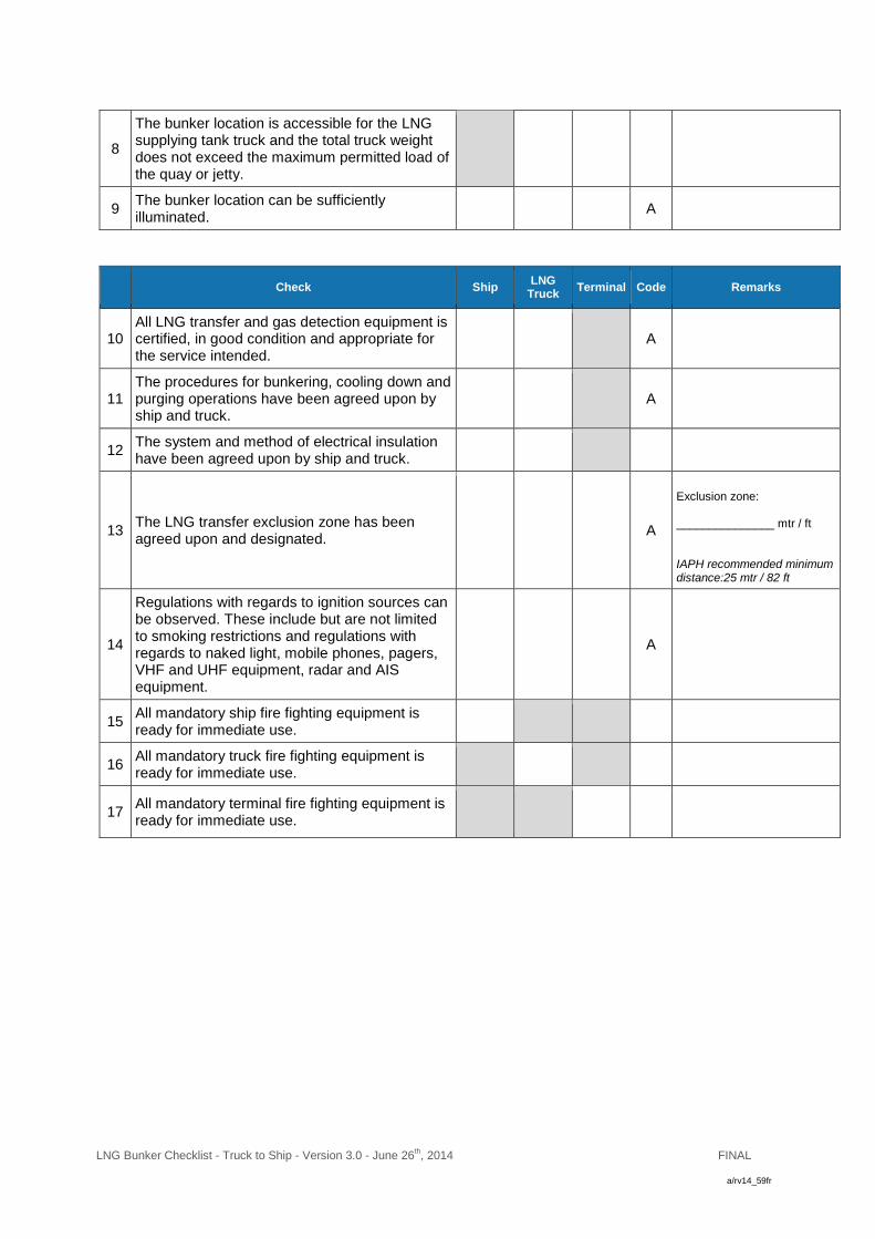
LNG Bunker Checklist - Truck to Ship - Version 3.0 - June 26th, 2014
FINAL
a/rv14_59fr
8
The bunker location is accessible for the LNG supplying tank truck and the total truck weight does not exceed the maximum permitted load of the quay or jetty.
9 The bunker location can be sufficiently illuminated.
A
Check Ship LNG
Truck Terminal Code Remarks
10 All LNG transfer and gas detection equipment is certified, in good condition and appropriate for the service intended.
A
11 The procedures for bunkering, cooling down and purging operations have been agreed upon by ship and truck.
A
12 The system and method of electrical insulation have been agreed upon by ship and truck.
13 The LNG transfer exclusion zone has been agreed upon and designated.
A
Exclusion zone: _______________ mtr / ft IAPH recommended minimum distance:25 mtr / 82 ft
14
Regulations with regards to ignition sources can be observed. These include but are not limited to smoking restrictions and regulations with regards to naked light, mobile phones, pagers, VHF and UHF equipment, radar and AIS equipment.
A
15 All mandatory ship fire fighting equipment is ready for immediate use.
16 All mandatory truck fire fighting equipment is ready for immediate use.
17 All mandatory terminal fire fighting equipment is ready for immediate use.

LNG Bunker Checklist - Truck to Ship - Version 3.0 - June 26th, 2014
FINAL
a/rv14_59fr
I. PART B: Pre Transfer Checklist
(This part should be completed before actual transfer operations start)
Check Ship LNG
Truck Terminal Code Remarks
18 Present weather and wave conditions are within the agreed limits.
A R
19
The LNG receiving ship is securely moored. Regulations with regards to mooring arrangements are observed. Sufficient fendering is in place.
R
20 There is a safe means of access between the ship and shore.
R
21 The bunker location is sufficiently illuminated.
A R
22 The ship and truck are able to move under their own power in a safe and non-obstructed direction.
R
23
Adequate supervision of the bunker operation is in place both on the ship and at the LNG tank truck and an effective watch is being kept at all times.
24
An effective means of communication between the responsible operators and supervisors on the ship and at truck has been established and tested. The communication language has been agreed upon.
A R
VHF / UHF Channel: ____ Language: ______________________ Primary System: ______________________ Backup System: ______________________
25 The emergency stop signal and shutdown procedures have been agreed upon, tested, and explained to all personnel involved.
A
Emergency Stop Signal: ______________________
26 The predetermined LNG transfer exclusion zone has been established. Appropriate signs mark this area.
A
27 The LNG transfer exclusion zone is free of unauthorized persons, objects and ignition sources.
R
28 External doors, portholes and accommodation ventilation inlets are closed as per operation manual.
R
At no time they should be locked
29 The gas detection equipment has been operationally tested and found to be in good working order.
30 Material Safety Data Sheets (MSDS) for the delivered LNG fuel are available.
A

LNG Bunker Checklist - Truck to Ship - Version 3.0 - June 26th, 2014
FINAL
a/rv14_59fr
Check Ship LNG
Truck Terminal Code Remarks
31
Regulations with regards to ignition sources are observed. These include but are not limited to smoking restrictions and regulations with regards to naked light, mobile phones, pagers, VHF and UHF equipment, radar and AIS equipment.
R
32 Appropriate and sufficient suitable protective clothing and equipment is ready for immediate use.
33
Personnel involved in the connection and disconnection of the bunker hoses and personnel in the direct vicinity of these operations make use of sufficient and appropriate protective clothing and equipment.
34 Hand torches (flashlights) are of an approved explosion proof type.
35 The water spray system has been tested and is ready for immediate use.
If applicable.
36 Spill containment arrangements are of an appropriate volume, in position, and empty.
37 Hull protection system is in place. If applicable.
38 Bunker pumps and compressors are in good working order.
A
If applicable.
39 All remote control valves are well maintained and in good working order.
40 Bunker system gauges, high level alarms and high-pressure alarms are operational, correctly set and in good working order.
41 The ship’s bunker tanks are protected against inadvertent overfilling at all times, tank content is constantly monitored and alarms are correctly set.
R
Intervals not exceeding
___________ minutes
42 All safety and control devices on the LNG installations are checked, tested and found to be in good working order.
43 Pressure control equipment and boil off or re-liquefaction equipment is operational and in good working order.

LNG Bunker Checklist - Truck to Ship - Version 3.0 - June 26th, 2014
FINAL
a/rv14_59fr
Check Ship LNG
Truck Terminal Code Remarks
44
Both on the ship and at the tank truck the ESDs, automatic valves or similar devices have been tested, have found to be in good working order, and are ready for use. The closing rates of the ESDs have been exchanged.
A
ESD Ship:
____________ seconds
45 Initial LNG bunker line up has been checked. Unused connections are closed, blanked and fully bolted.
46
LNG bunker hoses, fixed pipelines and manifolds are in good condition, properly rigged, supported, properly connected, leak tested and certified for the LNG transfer.
47 The LNG bunker connection between the ship and the truck is provided with dry disconnection couplings.
If applicable.
48 The LNG bunker connection between the ship and the LNG bunker truck has adequate electrical insulating means in place.
49
Dry breakaway couplings in the LNG bunker connections are in place, have been visually inspected for functioning and found to be in a good working order.
A
50 The tank truck is electrically grounded and the wheels are chocked.
51 The tank truck engine is off during the connection, purging and disconnection of the LNG bunker hoses.
52 The tank truck engine is switched off during transfer.
Unless the truck engine is required for transfer of LNG.
53 The ship’s emergency fire control plans are located externally.
Location: ______________________
54 An International Shore Connection has been provided.
55 The LNG specifications have been agreed upon by ship and truck.
A
e.g. quality, temperature and density of the LNG.
56
Port authorities have been informed that bunker transfer operations are commencing and have been requested to inform other vessels in the vicinity.

LNG Bunker Checklist - Truck to Ship - Version 3.0 - June 26th, 2014
FINAL
a/rv14_59fr
I. PART C: LNG Transfer Data (This part should be completed before actual transfer operations start)
Agreed starting temperatures and pressures LNG receiving ship LNG supplying truck
LNG tank start temperature: °C / °F
LNG tank start pressure: bar / psi (abs)
Agreed bunker operations
Note the agreed Physical Quantity Unit (PQU): m3 Tonnes _____________
Tank 1 Tank 2
Agreed quantity to be transferred: PQU
Starting pressure: bar / psi
(abs)
Starting rate: PQU
per hour
Max transfer rate: PQU
per hour
Topping of rate: PQU
per hour
Max pressure at manifold: bar / psi
(abs)
Agreed maximums and minimums Maximum Minimum
Maximum working pressure: bar / psi (abs)
Maximum and minimum pressures in the LNG bunker tanks: bar / psi
(abs)
Maximum and minimum temperatures of the LNG: °C / °F
Maximum filling limit of the LNG bunker tanks: %

LNG Bunker Checklist - Truck to Ship - Version 3.0 - June 26th, 2014
FINAL
a/rv14_59fr
Declaration
We, the undersigned, have checked the above items in chapter I parts A, B and C in accordance with the instructions and have satisfied ourselves that the entries we have made are correct.
We have also made arrangements to carry out repetitive checks as necessary and agreed that those items coded ‘R’ in the checklist should be re-checked at intervals not exceeding ______ hours.
If, to our knowledge, the status of any item changes, we will immediately inform the other party.
Ship LNG Truck Terminal
Name
Name Name
Rank
Position Position
Signature
Signature Signature
Date
Date Date
Time
Time Time
Record of repetitive checks
Date
Time
Initials for ship
Initials for truck
Initials for terminal
Guideline for completing this checklist The presence of the letters ‘A’ or ‘R’ in the column entitled ‘Code’ indicates the following: A (‘Agreement’).
This indicates an agreement or procedure that should be identified in the ‘Remarks’ column of the checklist or communicated in some other mutually acceptable form.
R (‘Re-check’).
This indicates items to be re-checked at appropriate intervals, as agreed between both parties, at periods stated in the declaration.
P (‘Permission’)
This indicates that permission is to be granted by authorities. The joint declaration should not be signed until both parties have checked and accepted their assigned responsibilities and accountabilities. When duly signed, this document is to be kept at least one year on board of the LNG receiving vessel.

LNG Bunker Checklist - Truck to Ship - Version 3.0 - June 26th, 2014
FINAL
a/rv14_59fr
II. After LNG Transfer Checklist
(This part should be completed after transfer operations have been completed)
Check Ship LNG
Truck Terminal Code Remarks
57 LNG bunker hoses, fixed pipelines and manifolds have been purged and are ready for disconnection.
A
58 Remote and manually controlled valves are closed and ready for disconnection.
A
59 After disconnection the LNG transfer safety zone has been deactivated. Appropriate signs have been removed.
A
60 Local authorities have been notified that LNG bunker operations have been completed.
Time notified: _______________ hrs
61 The terminal has been notified that LNG bunker operations have been completed.
Time notified: _______________ hrs
62
Port authorities have been informed that bunker transfer operations have ceased and have been requested to inform other vessels in the vicinity.
63 Near misses and incidents have been reported to local authorities.
Report nr: _______________
Declaration
We, the undersigned, have checked the above items in chapter II in accordance with the instructions and have satisfied ourselves that the entries we have made are correct.
Ship LNG Truck Terminal
Name
Name Name
Rank
Position Position
Signature
Signature Signature
Date
Date Date
Time
Time Time

LNG Bunker Checklist - Truck to Ship - Version 3.0 - June 26th, 2014
FINAL
a/rv14_59fr
Guideline for completing this checklist The presence of the letters ‘A’ or ‘R’ in the column entitled ‘Code’ indicates the following: A (‘Agreement’).
This indicates an agreement or procedure that should be identified in the ‘Remarks’ column of the checklist or communicated in some other mutually acceptable form.
R (‘Re-check’).
This indicates items to be re-checked at appropriate intervals, as agreed between both parties, at periods stated in the declaration.
P (‘Permission’)
This indicates that permission is to be granted by authorities. The joint declaration should not be signed until both parties have checked and accepted their assigned responsibilities and accountabilities. When duly signed, this document is to be kept at least one year on board of the LNG receiving vessel.

Version 1.0 – June 10, 2014
Internal transfer, LNG Bunker Checklist (LNG cargo - LNG propulsion tank)
Note: The Internal transfer LNG Bunker Checklist is made in line with the IAPH procedures.
I. PART A: Pre Operations Checklist (This part should be completed before actual bunker operations start)
Date and time:
Port and Berth:
Ship name: Argos GL (LNG Bunker Vessel)
LNG cargo tank no.:
Check
Bunker Vessel
Code
Remarks
1
Local authorities have granted permission for LNG transfer operations for the specific location and time.
P
2
Local authorities have been notified of the start of LNG bunker operations as per local regulations.
Time notified: hrs
3
Local authorities requirements are being observed.
e.g. Port Bye Law.
4
The ship’s class approved bunker plan and operations manual are available.
5
The LNG bunker vessel is moored properly. A
6
The bunker location can be sufficiently illuminated.
A
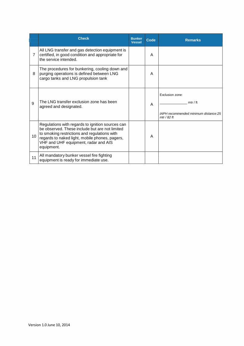
Version 1.0 June 10, 2014
Check
Bunker Vessel
Code
Remarks
7
All LNG transfer and gas detection equipment is certified, in good condition and appropriate for the service intended.
A
8
The procedures for bunkering, cooling down and purging operations is defined between LNG cargo tanks and LNG propulsion tank
A
9
The LNG transfer exclusion zone has been agreed and designated.
A
Exclusion zone:
mtr / ft
IAPH recommended minimum distance:25 mtr / 82 ft
10
Regulations with regards to ignition sources can be observed. These include but are not limited to smoking restrictions and regulations with regards to naked light, mobile phones, pagers, VHF and UHF equipment, radar and AIS equipment.
A
11
All mandatory bunker vessel fire fighting equipment is ready for immediate use.
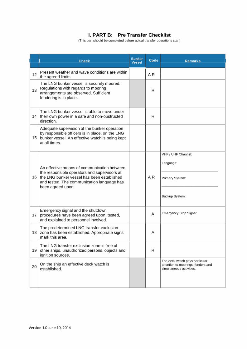
Version 1.0 June 10, 2014
I. PART B: Pre Transfer Checklist (This part should be completed before actual transfer operations start)
Bunker Vessel
Code
Check Remarks 12
Present weather and wave conditions are within the agreed limits.
A R
13
The LNG bunker vessel is securely moored. Regulations with regards to mooring arrangements are observed. Sufficient fendering is in place.
R
14
The LNG bunker vessel is able to move under their own power in a safe and non-obstructed direction.
R
15
Adequate supervision of the bunker operation by responsible officers is in place, on the LNG bunker vessel. An effective watch is being kept at all times.
16
An effective means of communication between the responsible operators and supervisors at the LNG bunker vessel has been established and tested. The communication language has been agreed upon.
A R
VHF / UHF Channel:
Language:
________________________________ Primary System:
________________________________ ___ Backup System:
17
Emergency signal and the shutdown procedures have been agreed upon, tested, and explained to personnel involved.
A
Emergency Stop Signal:
18
The predetermined LNG transfer exclusion zone has been established. Appropriate signs mark this area.
A
19
The LNG transfer exclusion zone is free of other ships, unauthorized persons, objects and ignition sources.
R
20
On the ship an effective deck watch is established.
The deck watch pays particular attention to moorings, fenders and simultaneous activities.

Version 1.0 June 10, 2014
Check Bunker-vessel
Code Remarks
21
External doors, portholes and accommodation ventilation inlets are closed as per operations manual.
R
At no time they should be locked
22 The gas detection equipment has been operational tested and found to be in good working order.
23
Material Safety Data Sheets (MSDS) for the LNG product are available.
A
24
Regulations with regards to ignition sources are observed. These include but are not limited to smoking restrictions and regulations with regards to naked light, mobile phones, pagers, VHF and UHF equipment, radar and AIS equipment.
R
25
Appropriate and sufficient suitable protective clothing and equipment is ready for immediate use.
26
Personnel involved in the connection and disconnection of the bunker hoses and personnel in the direct vicinity of these operations make use of sufficient and appropriate protective clothing and equipment.
27
Hand torches (flashlights) are of an approved explosion proof type.
28
The water spray system has been tested and is ready for immediate use.
29
Spill containment arrangements are of an appropriate volume, in position, and empty.
30
The hull protection system is in place.
31
Bunker pumps and compressors are in good working order.
A
32
All remote control valves are well maintained and in good working order.
33
Bunker system gauges, high level alarms and high pressure alarms are operational, correctly set and in good working order.
34
The ship’s bunker tanks are protected against inadvertent overfilling at all times, tank content is constantly monitored and alarms are correctly set.
R
Intervals not exceeding
minutes
35
All safety and control devices on the LNG installations are checked, tested and found to be in good working order.

Version 1.0 June 10, 2014
Bunker Vessel Check Code Remark
36 Pressure control equipment and boil off or re-
liquefaction equipment is operational and in good working order.
37
On the LNG bunker vessel the ESD’s, automatic valves have been tested, have found to be in good working order, and are ready for use. The closing rates of the ESD’s have been exchanged.
A
ESD LNG cargo tank: seconds
ESD LNG propulsion tank:
seconds
38
Initial LNG bunker line up has been checked. Unused connections are closed, blanked and fully bolted
39
LNG bunker hoses, fixed pipelines and manifolds are in good condition, properly rigged, supported, properly connected, leak tested and certified for the LNG transfer.
40
The LNG bunker connection between the ship and the LNG bunker vessel is provided with dry disconnection couplings.
41
Dry break away couplings in the LNG bunker connections are in place, visual inspected for functioning and found to be in a good working order.
A
42
The ship’s emergency fire control plans are located externally.
Location:
43
An International ESD Connection has been provided.
44
The LNG specifications is known and will be logged in the LNG propulsion log book
A
e.g. quality, temperature and density of the LNG.
45
Port authorities have been informed that bunker transfer operations are commencing and have been requested to inform other vessels in the vicinity

Version 1.0 June 10, 2014
I. PART C: LNG Transfer Data (This part should be completed before actual transfer operations start)
Agreed starting temperatures and pressures
LNG cargo tanks LNG propulsion tank
LNG cargo tank 1 start temperature:
°C / °F
LNG cargo tank 1 start pressure:
bar / psi (abs)
LNG cargo tank 2 start temperature:
°C / °F
LNG cargo tank 2 start pressure:
bar / psi (abs)
Agreed bunker operations
Note the agreed Physical Quantity Unit (PQU): m3 Tones
Tank 1 Tank 2
Agreed quantity to be transferred:
PQU
Starting pressure:
bar / psi (abs)
Starting rate:
PQU per hour
Max transfer rate:
PQU per hour
Topping of rate:
PQU per hour
Max pressure at manifold:
bar / psi (abs)

Version 1.0 June 10, 2014
Agreed maximums and minimums
Declaration I, the undersigned, (skipper or a person authorized by the skipper of the LNG bunker vessel) have checked the above items in chapter I in accordance with the instructions and have satisfied myself that the entries I have made are correct.
Bunker vessel
Name
Position
Signature
Date
Time
Guidelines for completing the Internal LNG cargo – LNG propulsion Bunker Checklist.
The presence of the letters ‘A’ or ‘R’ in the column entitled ‘Code’ indicates the following:
A (‘Agreement’). This indicates an agreement or procedure that should be identified in the ‘Remarks’ column of the checklist or communicated in some other form.
R (‘Re-check’).
This indicates items to be re-checked at appropriate intervals at periods stated in the declaration.
P (‘Permission’) This indicates that permission is to be granted by authorities.
The declaration should not be signed until both parties have checked and accepted their assigned responsibilities and accountabilities.This document is to be kept at least one year on board of the LNG bunker vessel.
Maximum Minimum
Maximum working pressure:
bar / psi (abs)
Maximum and minimum pressures in the LNG bunker tanks:
bar / psi (abs)
Maximum and minimum temperatures of the LNG:
°C / °F
Maximum filling limit of the LNG propulsion tank:
%

Version 1.0 June 10, 2014
II. After LNG Transfer Checklist
(This part should be completed after transfer operations have been completed)
Declaration
I, the undersigned, (skipper or a person authorized by the skipper of the LNG bunker vessel) have checked the above items in chapter II in accordance with the instructions and have satisfied myself that the entries I have made are correct.
Bunker vessel
Name
Position
Signature
Date
Time
Bunker Vessel
Check Code Remarks
46
LNG bunker hoses, fixed pipelines and manifolds have been purged and are ready for disconnection.
A
47
Remote and manual controlled valves are closed and ready for disconnection.
A
48
After disconnection the LNG transfer safety zone has been deactivated. Appropriate signs have been removed.
A
49
Local authorities have been notified that LNG bunker operations are completed.
Time notified:
hrs
50
Port authorities have been informed that bunker transfer operations have ceased and have been requested to inform other vessels in the vicinity.
51
Near misses and incidents have been reported to local authorities.
Report nr:

Version 1.0 June 10, 2014
Guidelines for completing the Internal LNG cargo – LNG propulsion Bunker Checklist.
The presence of the letters ‘A’ or ‘R’ in the column entitled ‘Code’ indicates the following:
A (‘Agreement’).
This indicates an agreement or procedure that should be identified in the ‘Remarks’ column of the checklist or communicated in some other form.
R (‘Re-check’).
This indicates items to be re-checked at appropriate intervals at periods stated in the declaration.
P (‘Permission’) This indicates that permission is to be granted by authorities.
The declaration should not be signed until both parties have checked and accepted their assigned responsibilities and accountabilities.This document is to be kept at least one year on board of the LNG bunker vessel.
***

Annex 5 Description of the training of the crew on board of LNG driven inland
waterway vessel Argos-GL
A. Introduction
The main purpose of the course is to familiarize the crew of inland waterway vessels with the
properties and hazards of LNG and to get knowledge how to work with LNG as fuel onboard the
vessel. For instance in case of operation, bunkering and maintenance.
The course will include a theoretical part, consisting of the topics mentioned under B and a practical
training on board the vessel in which the theoretical items will be dealt with in practice.
The selection of a suitable training institute and the extend of the training in accordance with the
competent authority. The training institute and the extend of the training shall be determined with the
competent authority. Every 2.5 years, the training shall be repeated.
After successful participation, the student shall be issued with a certificate by the training institute.
B. Contents of the LNG course
The LNG course will cover the following topics:
1. Legislation
1.1 General legislation / best practice for ADN, ROSR, European Directive EU
2006/87 and new developments
1.2 Available international legislation concerning LNG (for seagoing / best practices)
IMO, IMDG and new developments
1.3 Rules of the recognized classification societies
1.4 Legislation concerning health and safety
1.5 Local regulations and permits
1.6 Recommendations according to ADN and ROSR
2. Introduction to LNG
2.1 The definition of LNG, critical temperatures, LNG hazards, atmospheric conditions
2.2 Compositions and qualities of LNG, LNG- quality certificates
2.3 MSDS (safety sheet): physical / product characteristics
2.4 Environmental properties

3. Safety
3.1 Hazards and risks
3.2 Risk management
3.3 The use of personal protection
4. The techniques of the installation
4.1 General configuration
4.1 Explanation of the effects of liquefied natural gas
4.2. Temperatures and pressures
4.3 Valves and automatic controls, ATEX
4.4. Alarms
4.5 Materials (hoses, pressure relief valves)
4.6 Ventilation
5. Service & checks of the LNG installation
5.1 Daily maintenance
5.2 Weekly maintenance
5.3 Periodical maintenance
5.4 Failures
5.5 Documentation of maintenance work
6. Bunkering of LNG
6.1 Bunkering procedure LNG
6.4 Gas freeing / flushing of the LNG system
6.5 Check lists and delivery certificate
7. Maintenance
7.1 Gas free certificate
7.2 Gas freeing / flushing of the LNG system before docking
7.3 Inerting of the LNG system
7.4 Procedure de-bunkering of the bunker tank
7.5 First filling of the LNG bunker tank (cool down)
7.6 Start up after dock period

8. Emergency Scenario’s
8.1 Emergency plan
8.2 LNG Spill on deck
8.3 LNG skin contact
8.4 Release of natural gas on deck
8.5 Release of natural gas in enclosed spaces (power stations)
8.6 Fire on deck in the vicinity of the LNG storage tank.
8.7 Fire in engine rooms
8.8 Specific hazard in case of transport of dangerous goods
8.9 Grounding/collision of the vessel
C. The LNG training on board will cover the following topics:
9. Description of practical training on board
9.1 Get familiarized with the content of the ships management system, in particular the
chapters concerning the LNG installation.
9.2 Check safety awareness and the use of safety equipment for LNG
9.3 Awareness of monitoring, controls and alarms of the LNG installation on board.
9.4 Awareness of maintenance and control procedures of the LNG installation.
9.5 Awareness and familiarisation with the bunker procedure (preferable in practice)
9.6 Awareness of the maintenance procedures for docking
9.7 Awareness of the emergency scenarios

BUNKERSHIP LNG FUEL SYSTEM
Third party verification HAZID-study
Argos Bunkering B.V.
Report No.: PP103472-1, Revision: 0
Date: 2014-05-23

Project name: Bunkership LNG Fuel System Det Norske Veritas B.V.
Report title: Third party verification HAZID-study Solutions
Customer: Argos Bunkering B.V. P.O. Box 9599
Contact person: Mr. P. van den Ouden 3007 AN Rotterdam
Date of issue: 2014-05-23 The Netherlands
Project No.: PP103472 +31 (0)10 29 22 600
Organisation unit: Solutions (OEENL411)
Report No.: PP103472-1, revision 0
Summary:
Report of the Third Party verification of the HAZID-study of the LNG fuel system for the new gasoil/LNG
fuelled bunkership of Argos Bunkering B.V. The HAZID-study was performed on April 15th and 16th, 2014
in Capelle aan den IJssel.
Prepared by: Verified by: Approved by:
Peter Petersen Senior Consultant
Matthé Bakker Head
of Section Solutions
Netherlands
Matthé Bakker Head
of Section Solutions
Netherlands
☐ Unrestricted distribution (internal and external) Keywords:
☐ Unrestricted distribution within DNV GL
☒ Limited distribution within DNV GL after 3 years
☐ No distribution (confidential)
☐ Secret
Reference to part of this report which may lead to misinterpretation is not permissible.
Revision Date Reason for Issue Prepared by Verified by Approved by
Draft
2014-05-23
For comments
Peter Petersen
Matthé Bakker
Matthé Bakker
0 2014-05-21 Client comments incorporated Peter Petersen Matthé Bakker Matthé Bakker

DNV GL – Report no. PP103472-1, Revision 0 – www.dnvgl.com Page i
Table of content 1 INTRODUCTION .............................................................................................................. 1
2 REVIEW RESULTS ........................................................................................................... 2
2.1 Preparation of the HAZID-study 2
2.2 Study objective and scope 2
2.3 Study documents 3
2.4 Applied methodology 3
2.5 Risk matrix 4
2.6 Study sections 4
2.7 Team members 4
2.8 Study report 4
3 STUDY SESSIONS ........................................................................................................... 5
3.1 Introduction 5
3.2 Observations 5
4 CONCLUSION ................................................................................................................. 6

DNV GL – Report no. PP103472-1, Revision 0 – www.dnvgl.com Page 1
1 INTRODUCTION
As part of the design process of the LNG fuel system for the new gasoil/LNG fuelled bunker ship of Argos
Bunkering B.V. several studies are being performed. These studies include risk identification studies,
such as HAZID (HAZard IDentification) and HAZOP (HAZard & OPerability) studies.
On request of Argos Bunkering B.V. (Argos), Det Norske Veritas (DNVGL) has performed a third party
verification of the HAZID-study that was performed on April 15th and 16th, 2014 in Capelle aan den IJssel.
The objective of the verification was to evaluate the preparation, execution and reporting of the study.
As part of the verification the study sessions have been attended by DNVGL (observer), furthermore the
following subjects have been reviewed:
Study scope and objective;
Study documents;
Applied methodology;
Selection of study nodes;
Study team composition;
Level of detail of the discussions;
Content and quality of study report.
In forelying report the results of the verification and the observations during the study sessions are
summarized.

DNV GL – Report no. PP103472-1, Revision 0 – www.dnvgl.com Page 2
2 REVIEW RESULTS 2.1 Preparation of the HAZID-study
As part of the preparation of the HAZID-study, the Terms of Reference (ToR) were drafted by Lloyds
Register Consulting (study facilitator and scribe). In the ToR a general introduction of the study objective,
scope, documents, methodology and risk rating system (risk matrix) are given. Furthermore a brief
description of the characteristics of LNG and an overview of historical incidents with LNG are included.
Prior to the study sessions the participants were provided with a copy of the ToR and requested to
familiarise themselves with the methodology, risk rating system and the main design documents.
Observations
The ToR contains the information that is required for the study participants to familiarise themselves
with the study objective, methodology and subject.
2.2 Study objective and scope
The study objectives are laid down in the ToR-document, the main objectives are to identify:
- Hazards and their causes;
- The resulting consequences;
- Existing safeguards and measures;
- Recommendations to eliminate or minimise risks.
Distinction is made between recommendations to prevent leaks and recommendations to mitigate the
consequences of a leak.
The ToR includes a description of the scope of the study (LNG fuel system), the following operating
modes are specifically mentioned:
- Normal operation;
- Start-up;
- Normal shutdown;
- Emergency shutdown.
A brief description of the LNG fuel system is given and reference is made to the main (engineering)
documents.
Observations
From the description in the ToR it is concluded that the main study objective was to identify and discuss
loss of containment events and safety risks. The objective to identify causes, consequences, safeguards
and recommendations for improvement provides the basis for proper hazard identification and risk
evaluation. The study objective is similar to the objective of HAZID studies that are performed in other
industry sectors, although the identification of environmental risks and financial risks (e.g. availability) is
not included. Note: loss of containment is one of the direct causes for environmental and financial risks.
The scope of the study (LNG fuel system) is clearly indicated in the ToR, reference is made to the main
(engineering) documents. Since most study participants were involved in the project and familiar with
the development of the LNG fuel system the brief description of the system is considered sufficient.

DNV GL – Report no. PP103472-1, Revision 0 – www.dnvgl.com Page 3
2.3 Study documents
Prior to the study the underneath mentioned documents were made available to the participants. During
the study, each participant was provided with a hardcopy of these documents.
Drawing number Description
50102448 TN01, rev. 00, dated 14-04-2014 Terms of Reference
--- General description of the ‘Gasoil/LNG bunkership’
project
1406-1100-100 page TB01, rev. 0, dated 17-03-2014 P&ID LNG fuel system
1406-1100-100 page TC01, rev. 0, dated 17-03-2014 P&ID LNG fuel system
1406-1100-100 page TD01, rev. 1, dated 21-03-2014 P&ID LNG fuel system
10 sheet 1 of 1, rev. 0, dated 05-03-2014 General arrangement (GTT tanks)
10 sheet 1 of 1, rev. 0, dated 31-12-2013 Hazard area plan
502 sheet 1 of 7, rev. 0, dated 06-03-2014 Foreship layout
502 sheet 2 of 7, rev. 0, dated 06-03-2014 Foreship layout
502 sheet 3 of 7, rev. 0, dated 06-03-2014 Foreship layout
502 sheet 5 of 7, rev. 0, dated 17-03-2013 Foreship layout - Ventilation ground system
502 sheet 6 of 7, rev. 0, dated 17-12-2013 Foreship layout - Ventilation channel details
502 sheet 7 of 7, rev. 0, dated 17-12-2013 Foreship layout - Ventilation ground system
503 sheet 1 of 2, rev. 0, dated 10-02-2014 LNG propulsion room layout
503 sheet 2 of 2, rev. 0, dated 10-02-2014 LNG propulsion room layout
003 A0001 sheet 1 of 2, rev. 1, dated 25-01-2013 Single line diagram drive network 500V AC
003 A0001 sheet 1 of 2, rev. 1, dated 01-02-2013 Single line diagram 400V AC boardnet
--- Ventilation calculations gas engine room
--- Overview of protection system/levels
Observations
The documents were sent to the study participants for familiarisation and preparation for the study. Most
participants were involved in the development of (a part of) the LNG fuel system and sufficient time was
available for other participants to prepare themselves.
2.4 Applied methodology
The methodology for the HAZID study is described in the ToR. The general approach and the basic
elements of the methodology are explained, the main elements are:
- Definition of the equipment;
- Identification of deviations and causes;
- Evaluation of consequences;
- Evaluation of safeguards;
- Recommendations.
The description includes a list with subjects (HAZID prompts) that forms the basis for the study and is
used to initiate discussions on possible causes and scenarios.
Observations
The selected methodology is commonly used in various industry sectors for identification of hazards and
risks in early project stages. The HAZID prompts are selected taking the characteristics of LNG and the
design of the LNG fuel system into account.
The description of the methodology and selected subjects (HAZID prompts) in the ToR gives sufficient
information for the study participants.
DNV GL – Report no. PP103472-1, Revision 0 – www.dnvgl.com Page 4
2.5 Risk matrix
In order to determine whether additional safeguards are needed and to determine the type of required
safeguards a risk matrix is used. The risk matrix, as proposed by Lloyd’s Register Consulting, is included
in the ToR. A brief explanation of the purpose and the risk rating method is given.
Observations
The risk matrix is proposed by Lloyd’s Register Consulting and has been accepted by Argos prior to the
study sessions. The risk matrix is similar to other matrices that are used in the industry for HAZID
studies, for detailed risk identification studies (such as HAZOP) usually more detailed matrices are used.
In accordance with the objective of the study the matrix includes a scale for safety consequences only.
2.6 Study sections
A (provisional) split of the LNG fuel system in 4 study sections is included in the ToR:
- Vacuum insulated LNG tank;
- PBU/vaporizer and closed loop hot water heating system;
- Natural gas fuel supply to the GNG engines;
- Ventilation system on the cold box.
Observations
The LNG fuel system is split into study sections taking into account the complexity, size and function of
the system. The resulting four sections provide a proper basis for a complete and thorough study. During
the study it was decided to add a 5th section: “Engine room ventilation system”.
2.7 Team members
An overview of identified team members is included in the ToR. The expertise/function of the members
and their role during the HAZID study is included.
Observations
Representatives from the companies involved in the design and the assessment of the fuel system were
invited for the study. In the HAZID-report a detailed overview of the expertise and experience of the
team members is given. Sufficient knowledge and experience with respect to design, operation and
approval of gasoil/LNG fuel systems and associated systems was available during the sessions.
2.8 Study report
The results of the HAZID study and details with respect to the organisation and execution of the study
are laid down in the report of Lloyds Register Consulting (ref. 50102448 rev. 00, dated 29 April 2014).
The report contains the following (main) subjects:
- Description of the fuel system, including reference to design documents;
- HAZID objective and description of applied methodology;
- HAZID study team, including member expertise and experience;
- Study log sheets (causes, consequences, safeguards, recommendations);
- Summary of findings and conclusions.
Observations
The contents and level of detail of the report are similar to HAZID-reports that are produced in other
industry sectors. The report contains the required information for future reference and for further
development of the fuel system design.

DNV GL – Report no. PP103472-1, Revision 0 – www.dnvgl.com Page 5
3 STUDY SESSIONS 3.1 Introduction
To verify the results of the document review and to evaluate the application of the methodology DNVGL
has attended the study sessions that were held on April 15th and 16th, 2014 in Capelle aan den IJssel.
DNVGL was present on April 15th and the morning session of April 16th.
3.2 Observations
In this paragraph a summary is given of the findings and observations of DNVGL.
- The meeting place for the sessions provided sufficient space for the team members. The tables were
set up in U-form which assured that all team members had a clear view on the projector screen.
Enough table space was available for team members to lay out drawings and other documentation.
- Specific software for hazard and risk identification studies was used for recording the discussions
during the sessions. The study sections and the list with subjects (HAZID prompts), as identified
during the preparation for the study, were incorporated in the software.
- Real-time recording and projecting the log sheets on a screen allowed the team members to
comment on the content and wording of the identified scenarios.
- Full reporting was used, this means that all discussed topics are recorded, even those that the team
considered less relevant for safety (“No causes identified”, “No consequences identified”).
- Representatives from the companies involved in the design and the assessment of the fuel system
were included in the study team. In addition to the persons mentioned in the ToR additional team
members were present during the sessions.
- Each participant was provided with hard copies of drawings and other relevant documentation. The
HAZID sections were clearly indicated on the Piping & Instrumentation Diagrams (colour coded).
- At the beginning of the first session an explanation of the background of the development of the LNG
fuel system was given by Argos.
- The HAZID methodology, the objective and the study approach were explained by the study leader.
- Prior to the discussion/analysis of each study section an explanation on the design and operation of
the section was given. During the study it was decided to add a 5th section: “Engine room ventilation
system”, detailed information for this system was not available during the session.
- During the sessions explanations and clarifications on the design of the fuel system were given (Argos,
Cryonorm, MWM Benelux, Windex, …).
- Sufficient time was available for (detailed) discussions during the sessions. Where appropriate, team
members participated in the discussions.
- Based on the discussions and questions that were raised during the sessions, the list with HAZID
prompts (discussion subjects) was adapted. For example, the subject ‘Water’ was added to make sure
that issues with respect to the possible presence of water were properly discussed and analysed.
- Although the main objective of the study was identification of hazards, consequences and existing
safeguarding measures, the participants were occasionally allowed to discuss solutions and other
improvements in detail (‘engineering discussions’).
- At appropriate intervals breaks were held.

DNV GL – Report no. PP103472-1, Revision 0 – www.dnvgl.com Page 6
4 CONCLUSION
The methodology that was selected for the performance of the Hazard Identification study is commonly
used in various industry sectors. The methodology and approach were adapted taking the characteristics
of LNG and the design of the LNG fuel system into account.
During the sessions knowledge and experience with respect to design, operation and approval of
gasoil/LNG fuel systems and associated systems was available. Representatives from the companies
involved in the design and the assessment of the fuel system were present.
Information with respect to the study objective, methodology and subject has been timely sent to the
team members for familiarization and preparation for the sessions.
During the study sessions sufficient time was available for discussion and information exchange between
the team members.
The HAZID-report contains the required information for future reference and for further development of
the fuel system design

ABOUT DNV GL Driven by our purpose of safeguarding life, property and the environment, DNV GL enables organizations
to advance the safety and sustainability of their business. We provide classification and technical assurance along with software and independent expert advisory services to the maritime, oil and gas, and energy industries. We also provide certification services to customers across a wide range of industries. Operating in more than 100 countries, our 16,000 professionals are dedicated to helping our customers make the world safer, smarter and greener.

ZENTRALKOMMISSION FÜR DIE RHEINSCHIFFFAHRT RV (14) 59 RV/G (14) 92
JWG (14) 86 25. September 2014
Or. nl fr/de/nl/en
UNTERSUCHUNGSAUSSCHUSS
ARBEITSGRUPPE UNTERSUCHUNGSORDNUNG GEMEINSAME ARBEITSGRUPPE
Empfehlung für das Tankmotorschiff „Argos GL“ Mitteilung des Sekretariats
_____________________________________________________________________________________________________________________________
Das Sekretariat übermittelt zur Information anliegend die von der Arbeitsgruppe
Untersuchungsordnung nach § 2.19 RheinSchUO ausgesprochene Empfehlung.
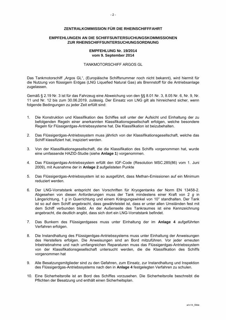
- 2 -
a/rv14_59de
ZENTRALKOMMISSION FÜR DIE RHEINSCHIFFFAHRT
EMPFEHLUNGEN AN DIE SCHIFFSUNTERSUCHUNGSKOMMISSIONEN
ZUR RHEINSCHIFFSUNTERSUCHUNGSORDNUNG
EMPFEHLUNG Nr. 19/2014
vom 9. September 2014
TANKMOTORSCHIFF ARGOS GL
Das Tankmotorschiff „Argos GL“, (Europäische Schiffsnummer noch nicht bekannt), wird hiermit für die Nutzung von flüssigem Erdgas (LNG Liquefied Natural Gas) als Brennstoff für die Antriebsanlage zugelassen.
Gemäß § 2.19 Nr. 3 ist für das Fahrzeug eine Abweichung von den §§ 8.01 Nr. 3, 8.05 Nr. 6, Nr. 9, Nr.
11 und Nr. 12 bis zum 30.06.2019. zulässig. Der Einsatz von LNG gilt als hinreichend sicher, wenn
folgende Bedingungen zu jeder Zeit erfüllt sind:
1. Die Konstruktion und Klassifikation des Schiffes soll unter der Aufsicht und Einhaltung der zu
befolgenden Regeln einer anerkannten Klassifikationsgesellschaft erfolgen, welche besondere Regeln für Flüssigerdgas-Antriebssysteme hat. Die Klassifikation ist beizubehalten.
2. Das Flüssigerdgas-Antriebssystem muss jährlich von der Klassifikationsgesellschaft, welche das
Schiff klassifiziert hat, inspiziert werden.
3. Von der Klassifikationsgesellschaft, die die Klassifikation des Schiffs vorgenommen hat, wurde
eine umfassende HAZID-Studie (siehe Anlage 1) vorgenommen.
4. Das Flüssigerdgas-Antriebssystem erfüllt den IGF-Code (Resolution MSC.285(86) vom 1. Juni
2009), mit Ausnahme der in Anlage 2 aufgelisteten Punkte
5. Das Flüssigerdgas-Antriebssystem ist so ausgeführt, dass Methan-Emissionen auf ein Minimum
reduziert werden.
6. Der LNG-Vorratstank entspricht den Vorschriften für Kryogentanks der Norm EN 13458-2.
Abgesehen von diesen Anforderungen muss der Tank mindestens einer Kraft von 2 g in
Längsrichtung, 1 g in Querrichtung und einem Krängungswinkel von 10° standhalten. Der Tank
ist so auf dem Schiff angebracht, dass gewährleistet ist, dass er unter allen Umständen fest mit
dem Schiff verbunden bleibt. An der Außenseite des Tankraumes ist eine Kennzeichnung
angebracht, die deutlich angibt, dass sich dort ein LNG-Vorratstank befindet.
7. Das Bunkern des Flüssigerdgases muss unter Einhaltung der im Anlage 4 aufgeführten
Verfahren erfolgen.
8. Die Instandhaltung des Flüssigerdgas-Antriebssystems muss unter Einhaltung der Anweisungen
des Herstellers erfolgen. Die Anweisungen sind an Bord mitzuführen. Vor jeder erneuten
Inbetriebnahme und nach umfangreichen Reparaturen muss das Flüssigerdgas-Antriebssystem
von der Klassifikationsgesellschaft untersucht werden, die die Klassifikation des Schiffs
vorgenommen hat
9. Alle Besatzungsmitglieder sind zu den Gefahren, zum Einsatz, zur Instandhaltung und Inspektion
des Flüssigerdgas-Antriebssystems nach den in Anlage 4 festgelegten Verfahren zu schulen. 10. Eine Sicherheitsrolle ist an Bord des Schiffes vorzusehen. Die Sicherheitsrolle beschreibt die
Pflichten der Besatzung und enthält einen Sicherheitsplan.

- 3 -
a/rv14_59de
11. Alle Daten zum Einsatz des Flüssigerdgas-Antriebssystems sind vom Betreiber zu erfassen und müssen mindestens fünf Jahre lang aufbewahrt werden. Die Daten sind der zuständigen Behörde auf Anfrage zuzuschicken.
12. Ein jährlicher Auswertungsbericht, der alle erfassten Daten enthält, wird zur Verteilung an die
Mitgliedstaaten an das Sekretariat der ZKR gesandt. Der Auswertungsbericht soll wenigstens die folgenden Informationen enthalten:
a) Systemausfall;
b) Leckage;
c) Bunkerdaten;
d) Druckdaten;
e) Abweichungen, Reparaturen und Änderungen des Flüssigerdgassystems einschließlich der Tanks;
f) Betriebsdaten;
g) Emissionsdaten, einschließlich Methan-Emissionen;
h) Prüfbericht der Klassifikationsgesellschaft, die die Klassifikation des Schiffs vorgenommen hat.
Anlagen:
Anlage 1: Bericht Nr. Loyd’s Register 50102448 R01 vom 29.4.2014
Anlage 2: Übersicht mit den Abweichungen vom IGF-CODE (IMO Resolution MSC.285 (86))
Anlage 3: Verfahren für das Bunkern von Flüssigerdgas
Anlage 4: Projektbeschreibung „Gasoil/LNG bunker ship project“
Annexes are located on website under RV 2014 EN rv14_59en_2
and RVG 2014 EN rvg14_92en_2
JWG 2014 EN jwg14_86en_2
Les annexes sont enregistrées sur le site sous RV 2014 EN rv14_59en_2
et RVG 2014 EN rvg14_92en_2
JWG 2014 EN jwg14_86n_2
Die Anlagen stehen auf der Website unter RV 2014 EN rv14_59en_2
und RVG 2014 EN rvg14_92en_2
JWG 2014 EN jwg14_86n_2
De bijlagen staan op de website onder RV 2014 EN rv14_59en_2
en RVG 2014 EN rvg14_92en_2
JWG 2014 EN jwg14_86n_2
***

COMMISSION CENTRALE POUR LA NAVIGATION DU RHIN RV (14) 59 RV/G (14) 92
JWG (14) 86 25 septembre 2014
Or. nl fr/de/nl/en
COMITE DU REGLEMENT DE VISITE GROUPE DE TRAVAIL DU REGLEMENT DE VISITE GROUPE DE TRAVAIL COMMUN
Recommandation pour le bateau-citerne « Argos GL »
Communication du Secrétariat _____________________________________________________________________________________________________________________________
Le Secrétariat a l'honneur de distribuer en annexe pour information la recommandation formulée par
le groupe de travail du règlement de visite conformément à l'article 2.19 du RVBR.

- 2 -
a_ext_vi/rv14_59fr_1
COMMISSION CENTRALE POUR LA NAVIGATION DU RHIN
RECOMMANDATIONS AUX COMMISSIONS DE VISITE
RELATIVE AU RÈGLEMENT DE VISITE DES BATEAUX DU RHIN
RECOMMANDATION N° 19/2014
du 9 septembre 2014
AUTOMOTEUR-CITERNE ARGOS GL
L'automoteur-citerne "Argos GL" (numéro européen unique d'identification des bateaux inconnu) est
autorisé par la présente à utiliser du gaz naturel liquéfié (GNL) en tant que combustible pour
l'installation de propulsion.
Conformément à l'article 2.19, chiffre 3, le bâtiment est autorisé à déroger aux dispositions des articles
8.01, chiffre 3 et 8.05, chiffres 6, 9, 11 et 12 jusqu'au 30.06.2019. L’utilisation du GNL est réputée
suffisamment sûre sous réserve que les conditions ci-après soient respectées à tout moment :
1. Le bâtiment doit être construit et classé conformément aux règles et sous le contrôle d'une
société de classification agréée ayant établi des règles spécifiques pour les installations
fonctionnant au GNL. La classe doit être maintenue.
2. Le système de propulsion au GNL doit être inspecté annuellement par la société de classification
qui a classé le bateau.
3. Une étude HAZID exhaustive doit avoir été réalisée par la société de classification qui a classé le
bateau (voir annexe 1).
4. Le système de propulsion au GNL doit être conforme au code IGF (Résolution MSC.285(86) du
1er
juin 2009), à l'exception des points énoncés à l'annexe 2.
5. Le système de propulsion au gaz naturel liquéfié doit être conçu de manière à limiter autant que
possible les émissions de méthane.
6. Le réservoir de stockage de GNL doit être conforme aux exigences de la norme EN 13458-2
relatives aux réservoirs à basse température. Outre cette exigence, le réservoir doit résister à
une poussée de 2 g dans le sens longitudinal et d'1 g dans le sens transversal ainsi qu'à un angle
de gîte de 10°. Le réservoir de stockage doit être installé à bord du bateau de telle sorte qu'il y
demeure fixé en toutes circonstances. Sur la face externe du local où est placé le réservoir doit
être fixé un marquage indiquant clairement que s'y trouve un réservoir de stockage de GNL.
7. L'avitaillement de GNL doit être réalisé conformément aux procédures énoncées à l'annexe 4.
8. L'entretien du système de propulsion au GNL doit être assuré conformément aux instructions du
fabricant. Ces instructions doivent être conservées à bord. Préalablement à toute remise en service à la suite d'une réparation ou d'une modification substantielles, le système de propulsion au GNL doit être examiné par la société de classification qui a classé le bateau.
9. Tous les membres d’équipage doivent avoir suivi une formation sur les dangers, l’utilisation,
l’entretien et l’inspection du système de propulsion au GNL conformément aux procédures énoncées à l'annexe 4.
10. Un dossier de sécurité doit être prévu à bord du bâtiment. Le dossier de sécurité doit décrire les
tâches de l'équipage et doit comporter un plan de sécurité.

- 3 -
a_ext_vi/rv14_59fr_1
11. Toutes les données relatives à l’utilisation du système de propulsion au GNL doivent être
conservées par l'exploitant durant au moins cinq ans. Ces données doivent être communiquées à
l'autorité compétente sur demande.
12. Un rapport annuel d’évaluation comportant l’ensemble des données collectées doit être adressé
au Secrétariat de la CCNR pour distribution aux Etats membres. Ce rapport d'évaluation doit
comporter au minimum les informations suivantes :
a) panne du système ;
b) fuites ;
c) données relatives à l'avitaillement ;
d) données relatives à la pression ;
e) dérogations, réparations et modifications subies par le système GNL, réservoirs compris ;
f) données de fonctionnement ;
g) données relatives aux émissions, y compris les émissions de méthane ;
h) rapport d'inspection de la société de classification qui a classé le bateau. Annexes :
Annexe 1 : Rapport du Lloyds Register n° 50102448 R01 du 29.4.2014
Annexe 2 : Synthèse des dérogations au Code IGF (Résolution de l'OMI MSC.285(86)
Annexe 3 : Description du projet "Gasoil/LNG bunker ship project"
Annexe 4 : Procédure pour l'avitaillement de gaz naturel liquéfié
Annexes are located on website under RV 2014 FR rv14_59fr_2
and RVG 2014 FR rvg14_92fr_2
JWG 2014 FR jwg14_86fr_2
Les annexes sont enregistrées sur le site sous RV 2014 FR rv14_59fr_2
et RVG 2014 FR rvg14_92fr_2
JWG 2014 FR jwg14_86fr_2
Die Anlagen stehen auf der Website unter RV 2014 FR rv14_59fr_2
und RVG 2014 FR rvg14_92fr_2
JWG 2014 FR jwg14_86fr_2
De bijlagen staan op de website onder RV 2014 FR rv14_59fr_2
en RVG 2014 FR rvg14_92fr_2
JWG 2014 FR jwg14_86fr_2
***

CENTRALE COMMISSIE VOOR DE RIJNVAART RV (14) 59 RV/G (14) 92
JWG (14) 86 25 september 2014
Or. nl fr/de/nl/en
COMITÉ REGLEMENT VAN ONDERZOEK WERKGROEP REGLEMENT VAN ONDERZOEK GEMEENSCHAPPELIJKE WERKGROEP
Aanbeveling Motortankschip “Argos GL” Mededeling van het secretariaat _____________________________________________________________________________________________________________________________
Het secretariaat heeft het genoegen u hierbij ter informatie de door de Werkgroep Reglement van
onderzoek overeenkomstig artikel 2.19 van het ROSR geuite aanbeveling te doen toekomen.

- 2 -
a/rvg14_59nl
CENTRALE COMMISSIE VOOR DE RIJNVAART
AANBEVELINGEN AAN DE COMMISSIES VAN DESKUNDIGEN
MET BETREKKING TOT TOEPASSING VAN HET REGLEMENT ONDERZOEK SCHEPEN OP DE
RIJN
AANBEVELING Nr. 19/2014
van 9 september 2014
MOTORTANKSCHIP ARGOS GL
Voor het motortankschip “Argos GL”, (Europees scheepsidentificatienummer nog niet bekend), wordt bij deze de vergunning afgegeven voor het gebruik van vloeibaar aardgas (LNG, Liquefied Natural
Gas) als brandstof voor de voortstuwingsinstallatie.
Op grond van artikel 2.19, derde lid, mag bij genoemd schip worden afgeweken van de artikelen 8.01,
derde lid, 8.05, zesde lid, 8.05, negende lid, 8.05, elfde lid en 8.05, twaalfde lid, tot en met 30.06.2019.
Het gebruik van LNG wordt geacht voldoende veilig te zijn indien te allen tijde aan de volgende
voorwaarden wordt voldaan: 1. Het schip wordt gebouwd en geklasseerd onder toezicht en overeenkomstig de van toepassing
zijnde voorschriften van een erkend classificatiebureau dat specifieke voorschriften voor LNG-installaties hanteert. De klasse blijft gehandhaafd.
2. Het LNG-voortstuwingssysteem wordt jaarlijks gekeurd door het classificatiebureau dat het schip
heeft geklasseerd.
3. Een volledige HAZID-keuring door het classificatiebureau dat het schip heeft geklasseerd is
uitgevoerd (zie bijlage 1).
4. Het LNG-voortstuwingssysteem voldoet aan de IGF-Code (IMO-Resolutie MSC 285(86) van
1 juni 2009), behoudens de in bijlage 2 vermelde onderdelen.
5. Het LNG-voortstuwingssysteem is zodanig uitgevoerd dat uitstoot van methaan maximaal wordt
beperkt.
6. De LNG-opslagtank voldoet aan de voorschriften voor cryogene tanks overeenkomstig de EN
13458-2 standaard. Afgezien van deze eisen, moet de tank minimaal bestand zijn tegen een
kracht van 2 g in het horizontale vlak, 1 g in de verticale richting en een helling van 10°. De tank
is dusdanig op het schip aangebracht dat verzekerd is dat deze onder alle omstandigheden aan
het schip bevestigd blijft. Aan de buitenzijde van de tankruimte zijn tekens aangebracht die
duidelijk weergeven dat er zich daar een LNG-opslagtank bevindt.
7. Bunkeren van LNG wordt uitgevoerd conform de in bijlage 4 vermelde procedures.
8. Het onderhoud van het LNG-voortstuwingssysteem wordt uitgevoerd overeenkomstig de
instructies van de fabrikant. De instructies worden aan boord bewaard. Voordat het
voortstuwingssysteem opnieuw in bedrijf wordt genomen en tevens na een omvangrijke reparatie,
moet het door het classificatiebureau dat het schip heeft geklasseerd, onderzocht worden.
9. Alle bemanningsleden zijn opgeleid in de bestrijding van gevaren alsmede in het gebruik, het
onderhoud en de inspectie van het LNG-voortstuwingssysteem overeenkomstig de in bijlage 4 vermelde procedures.
10. Een veiligheidsrol is beschikbaar aan boord van het schip. De veiligheidsrol beschrijft de taken
van de bemanning en bevat tevens een veiligheidsplan.

- 3 -
a/rvg14_59nl
11. Alle gegevens betreffende het gebruik van het LNG-voortstuwingssysteem worden verzameld
door de vervoerder en moeten minstens vijf jaar worden bewaard. Deze gegevens worden op verzoek naar de bevoegde autoriteit verzonden.
12. Er wordt jaarlijks een evaluatierapport, waarin alle verzamelde gegevens zijn opgenomen,
opgesteld en naar het secretariaat van de CCR gezonden, ter uitdeling onder de lidstaten. Dit evaluatierapport bevat ten minste de volgende informatie:
a) systeemuitval;
b) lekkage;
c) bunkergegevens;
d) drukgegevens;
e) afwijkingen, reparaties en wijzigingen van het LNG-systeem, de tank hieronder begrepen;
f) functioneringsgegevens;
g) uitstootgegevens, methaan hieronder begrepen;
h) verslag van het onderzoek opgesteld door het classificatiebureau dat het schip heeft geklasseerd.
Bijlagen:
Bijlage 1: Rapport Nr. Lloyd’s Register 50102448 R01 dated 29-4-2014
Bijlage 2: Overzicht van de afwijkingen van de IGF-code (IMO-Resolutie MSC.285(86)
Bijlage 3: Project beschrijving ‘Gasoil / LNG bunker ship project’
Bijlage 4: Procedure voor het bunkeren van vloeibaar aardgas
Annexes are located on website under RV 2014 EN rv14_59en_2
and RVG 2014 EN rvg14_92en_2
JWG 2014 EN jwg14_86en_2
Les annexes sont enregistrées sur le site sous RV 2014 EN rv14_59en_2
et RVG 2014 EN rvg14_92en_2
JWG 2014 EN jwg14_86n_2
Die Anlagen stehen auf der Website unter RV 2014 EN rv14_59en_2
und RVG 2014 EN rvg14_92en_2
JWG 2014 EN jwg14_86n_2
De bijlagen staan op de website onder RV 2014 EN rv14_59en_2
en RVG 2014 EN rvg14_92en_2
JWG 2014 EN jwg14_86n_2
***