for downloading d-meter - allen face · notice to international customers d-meter battery charger...
TRANSCRIPT

INSTRUCTION MANUAL
For
DownloadingD-Meter®
ALLEN FACE & COMPANY, L.L.C.2725 Old Wrightsboro Road
Building 12, Unit 5Wilmington, NC 28405
Tel: (910) 763-4501Fax: (910) 763-4502
Web: www.allenface.com
© 2009 Allen Face & Company, L.L.C. – All rights reserved.

Table Of Contents
Section I: BATTERY CHARGING, RE-CALIBRATION, & MAINTENANCE
Charging & Prolonging the Ni-Cad/Li-Ion Power Pack I-1Re-Calibration Requirements I-1Routine Maintenance I-1Returning Your Unit for Service I-2Prolonging Battery Performance I-3Notice to Overseas Customers I-4
Section II: SETTING-UP & OPERATING the DOWNLOAD SOFTWARE
Loading the D-Meter® Download Software onto Your PC’s Hard Drive II-1
Section III: GENERAL OPERATION
Recommended Run Pattern III-1Unit Power-Up & Memory Clearance III-1“Start New Session ?” Query III-1The “<OFF>” Screen III-2Zeroing The D-Meter *Version 3.06i and newer software eliminatedthe zeroing procedure * III-2-7Making a Run III-8Displaying Run Results III-8Check Codes III-9Automatic Retention of All Run Records III-9Downloading of All Run Records to Excel® III-9
Section IV: DETAILED KEY & LIGHT DESCRIPTIONS IV-1-2
Section V: DETAILED SCREEN DESCRIPTIONS
Status / Information Screens V-1Query Screens V-2Instruction Screens V-3Results Screens V-3Battery Status Screens V-4Error Message Screens V-4-5

Table Of Contents (cont)
Section VI: D-METER PROJECT MANAGEMENT VI-1
Section VII: STANDARD FF/FL FLOOR TOLERANCE SPECIFICATION VII-1
Section VIII: ACCEPTANCE OF TEST INSTRUMENTS VIII-1

I. BATTERY CHARGING, RE-CALIBRATION, & MAINTENANCE
A. Charging the Ni-Cad/ Li-Ion Power Pack (International Customers see Page I-4)
To charge / recharge the D-Meter’s internal power pack, plug the charger into a 115 volt groundedoutlet and plug the charger lead into the socket on the left hand side of the unit. Please see thenotice on prolonging battery performance on page I-3.
B. Re-Calibration Requirements
The D-Meter’s calibration is set at the factory and cannot be changed by the operator. Unless theunit is dropped or otherwise obviously damaged, the factory calibration should remain constantwell beyond the re-calibration period.
Every D-Meter must be returned to the factory annually (for domestic customers) or tri-annually(for international customers) for re-calibration and refurbishment to maintain the warranty. (Thereis a nominal charge for this service.) The re-calibration date is displayed on the D-Meter’s screenevery time the unit is turned on. Normal turn around time for all factory services is one week(excluding transit time). Replacement units may be borrowed free of charge, if a request is made atleast two weeks in advance (freight both ways to be paid by the borrower).
D-Meters in current calibration are fully warranted indefinitely for both parts and labor (absentobvious abuse).
C. Routine Maintenance
1. Use a commercial glass cleaner (e.g. Windex®) and a soft cloth to clean all exterior surfaces.NEVER use any type of organic solvent to clean the unit.
2. For the D-Meter software to work properly, the bottoms of the black rubber “shoes” mountedon the swivel feet must remain clean and properly positioned.
3. If the unit “hangs-up” and the display cannot be returned to the <OFF> screen by pressing the<STOP/ESC> key, reset the entire system by pressing the POWER <OFF> andPOWER<ON> keys. Only the readings in the run being recorded when the unit is reset willbe lost.
***************************************************************************************
Warning! The D-meter is a sealed unit. NEVER attempt to remove either of the end plates.
!!! IRREPARABLE ELECTRONIC DAMAGE WILL OCCUR !!!
***************************************************************************************
( I – 1 )

***************************************************************************************
Warning! NEVER immerse the unit.NEVER run the unit through standing water.NEVER expose the unit to steady rain.
!!! IRREPARABLE ELECTRONIC DAMAGE WILL OCCUR !!!
***************************************************************************************
Warning! All liabilities attendant to the use of any D-Meter shall reside entirely with theuser. AF&Co does not warrant the accuracy or adequacy of any of theinformation provided by the D-Meter and will not be liable for any damagessuffered as a consequence of any use thereof or reliance thereupon by any party.
***************************************************************************************
4. Questionable or troublesome units should be returned immediately to the factory for inspectionand repair along with a note describing the problems in detail.
5. When returning a unit for service or recalibration, please remove the manual and accessoriesfrom the case.
ALLEN FACE & COMPANY, L.L.C.2725 Old Wrightsboro Road
Building 12, Unit 5Wilmington, NC 28405
Tel: (910) 763-4501Fax: (910) 763-4502
Web: www.allenface.com
***************************************************************************************
Note: Please include your business card (or other identifying note) inside the case along withspecific instructions regarding billing and return shipment. Unless arranged otherwise,return shipment will be ground via a carrier of our choice
***************************************************************************************
( I – 2 )

!! READ THIS PAGE CAREFULLY !!
PROLONGING NI-CAD BATTERY PERFORMANCE
NOTE: IF YOUR METER IS EQUIPPED WITH A LI-ION BATTERY PACK THE FOLLOW-ING TEXT DOES NOT APPLY AND YOU CAN SKIP THIS PAGE. LI-IONBATTERIES CAN BE CHARGED AT ANY TIME AND DO NOT RETAIN AMEMORY.
IF YOUR METER IS EQUIPPED WITH A NI-CAD BATTERY PACK, PLEASE READTHE FOLLOWING:
REPEATED RE-CHARGING OF NI-CAD BATTERIES THAT HAVE NOT BEEN FULLYDISCHARGED AND/OR LEAVING THE BATTERY PACK CONNECTED TO THECHARGER LONGER THAN 8 HOURS CAN CAUSE THE NI-CAD BATTERIES TODEVELOP A “MEMORY”. THIS WILL REDUCE THE LENGTH OF TIME THAT THEBATTERY PACK WILL SUPPLY POWER TO THE METER. IF THIS HAPPENS, THEBATTERY PACK IS NOT “BAD”; IT JUST NEEDS RECONDITIONING.
THE CHARGER SUPPLIED WITH THE UNIT AUTOMATICALLY SHUTS DOWN AFTERTHE BATTERY PACK IS COMPLETELY CHARGED. WHEN YOU PLUG THE CHARGERINTO THE METER, THE RED LIGHT ON THE CHARGER INDICATES THAT THE UNIT ISCHARGING. WHEN THE RED LIGHT GOES OUT, THE BATTERY PACK IS FULLYCHARGED.
FOLLOW THE STEPS BELOW TO RECONDITION THE BATTERY PACK & MAXIMIZETHE METER’S RUN TIME:
1. AT LEAST ONCE A MONTH, TURN THE METER ON AND LET THE BATTERYDRAIN TILL THE METER SHUTS DOWN. (THIS WILL COMPLETELY DISCHARGETHE BATTERY PACK.)
2. AFTER FULL DISCHARGING, RECHARGE THE BATTERY PACK USING THECHARGER SUPPLIED WITH THE METER. LEAVE THE CHARGER CONNECTEDUNTIL ITS RED LIGHT GOES OFF (THUS INDICATING THAT THE BATTERY PACKIS FULLY CHARGED).
3. IF YOU NOTICE THAT THE UNIT IS “RUNNING DOWN” SOONER THAN YOUTHINK IT SHOULD, REPEAT STEPS 1 AND 2 ABOVE.
4. IF YOU STILL HAVE PROBLEMS, PLEASE CALL 910-763-4501
(I - 3)

NOTICE TO INTERNATIONAL CUSTOMERS
D-METER BATTERY CHARGER REQUIREMENTS
The battery charger supplied with your D-Meter is designed to operate on 60 cycle, 115 volt, ACelectricity. If your electricity is different, you will have to acquire an appropriate battery chargerfrom your local electronics supplier.
The replacement battery charger should have the following operating characteristics:
Output Voltage : 11 - 13 volts DCOutput Current : 500 - 800 milliampsPolarity : Center pole positive ( + )
WARNING ! DO NOT USE A CHARGER OF OPPOSITE POLARITY ! USING ACENTER POLE NEGATIVE ( - ) CHARGER WILL DESTROY THEUNIT’S CIRCUIT BOARD !
If you want to splice the plug off the charger we supplied onto your charger, please note that theWHITE STRIPED wire is the POSITIVE ( + ) lead.
BARREL ( - ) NEGATIVE
CENTER HOLE ( + )POSITIVE
( I – 4 )

II. SETTING-UP & OPERATING the DOWNLOAD SOFTWARE
A. Loading the F/D-Meter® Download Software onto Your PC’s Hard Drive
The Download Manager is available at our web site www.AllenFace.com under the meterdownloads tab.
The following instructions should be followed to correctly install the Allen Face DownloadManager software.
1. Uninstall any existing version of the Allen Face download programs. To remove go to ControlPanel>Add Remove Programs ( Programs and Features in Vista and Windows 7). Locate theAllen Face Download Manager and click uninstall.
2. At our web site www.AllenFace.com click on the meter downloads tab and scroll to thebottom of the page and open the zipfile “3mb” at the bottom of the page. Extract the file.
3. Double click on the AllenFace.Meter.Install.msi and follow the setup instructions. Acceptingthe defaults will work for most installations.
4. Once the program is installed, a shortcut will appear on your desktop. Double click to launchthe manager.
5. Install the driver for the USB to Serial adapter that was supplied with the meter (if this is ameter that was recently purchased).
B. System Requirements
1. Intel x86 or x64 processor, 512 MB RAM, Intel Duo Core Processor or above.
2. Operating Systems A. Windows XP sp3 B. Windows Vista C. Windows 7
3. Net Framework 3.5 sp1 – Typically downloaded via Windows Update
C. Running the F/D-Meter® Download Software
Please download the PDF under the zip file at our web site. This file will explain how to use the newdownload and its features.
(II – 1)

III. GENERAL OPERATION
A. Recommended Run Pattern
Select the run pattern to be measured. ASTM E-1155 (see Appendix) requires that measurementlines conform to one of the following two schemes:
1. Runs parallel and perpendicular to the longest slab boundary, where the aggregate run length ineach direction is approximately equal, or
2. Runs of any length all oriented at 45o to the longest slab boundary.
It is strongly recommended that all tests always be performed using an “X” the bays approach –even if the N/S and E/W column spacing are net exactly equal. Standardizing the run pattern on thebay diagonals offers a number of practical advantages:
1. The minimum q and z sampling requirement will always be well satisfied.2. Uniform coverage is automatically obtained.3. No run location decisions are required of the operator.4. No measurement line diagrams ever have to be produced or archived.5. Straight line runs without the aid of a taught string reference is facilitated.6. Tests can always be easily duplicated in the future.7. Results from different projects can always be reasonably compared.
B. Unit power-up & Memory Clearance
Press the <ON> button to turn the unit ON. Observe the various system status screens duringpower up. Respond to all memory status inquiries as prompted:
Pressing the <VOID PREV RUN> button at the VOID Clears Memory prompt initiates thememory clearance routine. Pressing the <GO/OK> button at the Are You Sure? query will thenpermanently delete all resident run records from memory by writing zeros over their memorylocations. Be careful! Cleared (and voided) runs are unrecoverable.
Pressing <STOP/ESC> exits the memory clearance routine at any prompt.
C. Start New Session? Query
If the operation mode remains unchanged from the previous power up, the Start New Session?query will appear. Pressing the <STOP/ESC> key (to answer "NO") to this query will cause theruns collected during this power up to be added to those of the previous active session. Pressingthe <GO/OK> key (to answer "YES") to this query will close the previous active session and putthe runs collected during this power up into their own new session number.
(III – 1)
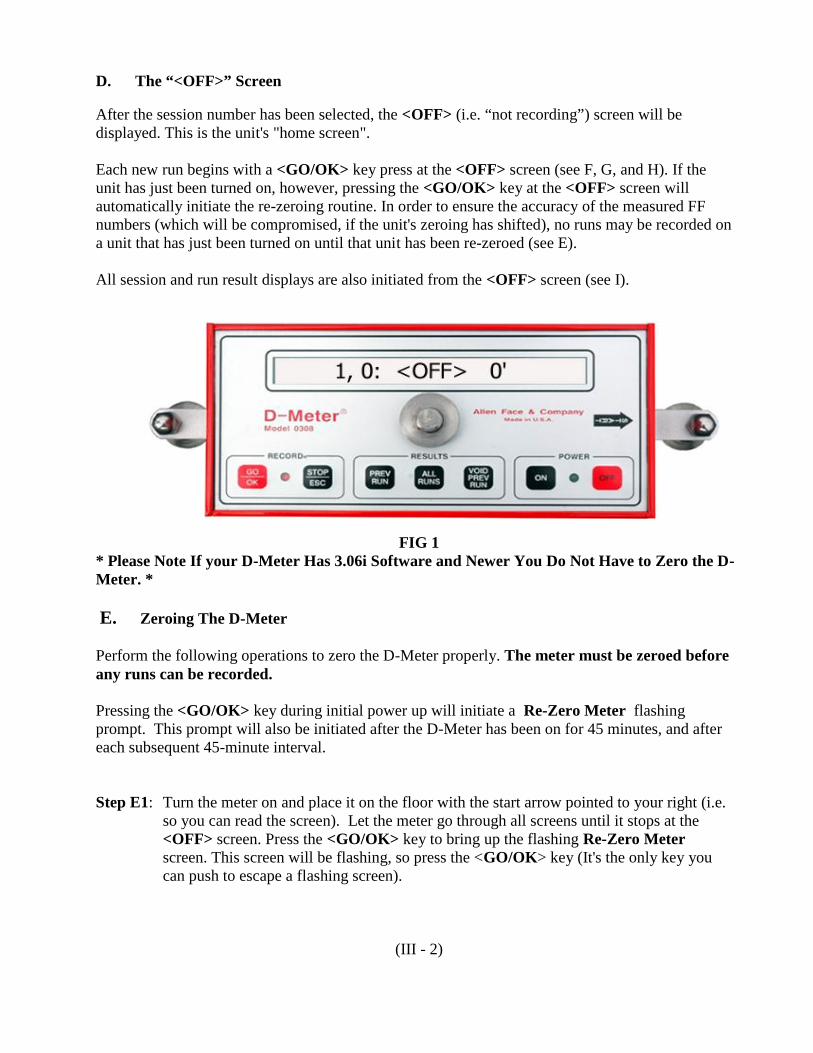
D. The “<OFF>” Screen
After the session number has been selected, the <OFF> (i.e. “not recording”) screen will bedisplayed. This is the unit's "home screen".
Each new run begins with a <GO/OK> key press at the <OFF> screen (see F, G, and H). If theunit has just been turned on, however, pressing the <GO/OK> key at the <OFF> screen willautomatically initiate the re-zeroing routine. In order to ensure the accuracy of the measured FFnumbers (which will be compromised, if the unit's zeroing has shifted), no runs may be recorded ona unit that has just been turned on until that unit has been re-zeroed (see E).
All session and run result displays are also initiated from the <OFF> screen (see I).
FIG 1* Please Note If your D-Meter Has 3.06i Software and Newer You Do Not Have to Zero the D-Meter. *
E. Zeroing The D-Meter
Perform the following operations to zero the D-Meter properly. The meter must be zeroed beforeany runs can be recorded.
Pressing the <GO/OK> key during initial power up will initiate a Re-Zero Meter flashingprompt. This prompt will also be initiated after the D-Meter has been on for 45 minutes, and aftereach subsequent 45-minute interval.
Step E1: Turn the meter on and place it on the floor with the start arrow pointed to your right (i.e.so you can read the screen). Let the meter go through all screens until it stops at the<OFF> screen. Press the <GO/OK> key to bring up the flashing Re-Zero Meterscreen. This screen will be flashing, so press the <GO/OK> key (It's the only key youcan push to escape a flashing screen).
(III - 2)

FIG 2
Step E2: This flashing screen is telling you that the D-Meter has to be zeroed before you canproceed. Press the <GO/OK> key.
FIG 3
Step E3: The next screen will say Want To Continue? (Fig 3). If you want to proceed with thezeroing procedure, press the <GO/OK> key. If not, press the <STOP/ESC> key to goback to the <OFF> screen.
Step E4: The flashing PUSH <GO> When Ready screen (Fig 4) will come up next. When you'vegotten the meter into position to take the first zero reading, and have marked the posi-tions of the feet on the floor with a pencil, push the <GO/OK> key. The meter will thendisplay the Do Not Move screen (Fig 5) and take the required reading. Be sure to holdthe unit as still and perpendicular as possible while this measurement is being taken.
(III-3)

FIG 4
FIG 5
FIG 6
(III-4)

Step E5: After the initial zeroing reading is taken, the Reverse Meter screen will appear (Fig 6).This screen directs you to pick the meter up and reverse it end-for-end. Using yourpencil marks, put the left foot on the floor where the right foot was, and put the right footon the floor where the left foot was.
The start arrow should now be pointing to your left (Fig 7). The Reverse Meter screenwill disappear after a few seconds, and the flashing PUSH <GO> When Ready screenwill appear again
FIG 7
Step E6: When you're ready to take the second zeroing reading, push the <GO/OK> key. Themeter will then display the Do Not Move screen (Fig 8) and take the required reading.Be sure to hold the unit as still as possible while this measurement is being taken.
FIG 8
(III-5)

Step E7: There are now 2 possibilities. Either:
1) The zeroing was successful, in which case the Meter Is Zeroed screen (Fig 10 - rev)will appear briefly, and the unit will then return to the <OFF> screen - leaving youready to make your first run.
or
2) The zeroing was unsuccessful, in which case the Zeroing Failed and Do ZeroingAgain screens will appear briefly, and the unit will then start flashing the PUSH<GO> When Ready screen - sending you back to Step E4.
FIG 9
FIG 10 (reversed)
(III-6)

F. Starting the Run
Step F1: After the unit has been zeroed, the meter automatically goes back to the <OFF> screen(Fig 11). You are now ready to make a run.
To start a run, place the meter on the floor at the first reading position with the STARTarrow pointing down the run.
FIG 11
Step F2: Holding the handle straight up and down, press the <GO/OK> key. The maximumallowable run length message will appear briefly, the RED and GREEN lights will gooff; and the screen will then go blank while the first reading is being taken. Once thefirst reading has been recorded, the RED and GREEN lights will come back on, and ascreen like that shown in Fig 12 will appear - showing you the distance measured, thevalue recorded, and the direction down the run.
FIG 12
(III-7)

G. Continuing the Run
Step G1: Push the handle away from you to tilt the unit forward on its front foot, slightly raisingthe rear foot off the floor. As soon as you start to move the unit, the RED and GREENlights will go off, and the screen will go blank. Without letting the front foot slide on thefloor, simultaneously twist and pull back on the handle to rotate the unit 1800. Set the oldrear foot down on the run line in front of the front pivot foot - in effect, making a stepdown the run line. The unit is now in the next reading position.
***************************************************************************************
Warning! When making a run, never move the unit while the screen and lights are off. Ifyou don't wait for the screen and lights to come back on before initiating thenext step, no reading will be taken, the reading sequence will be compromised,and the FF and FL results will be invalid.
The direction arrows shown in Fig 12 can be used at any time to check whether areading has been skipped. They must always point in the direction that thereadings are being taken. Otherwise, the run has been corrupted.
***************************************************************************************
Step G2: Hold the handle upright and keep still until the next reading is taken - whereupon theRED and GREEN lights and screen will come back on - thereby indicating that the unitis ready to take another step down the run line. Now, either go back to Step G1 (if youwant to take another reading), or go ahead to Step H1 (if you want to end the run).
H. Ending the Run
Step H1: Every D-Meter run must be between 11 feet and 240 feet long. Within this range of runlengths, a run may be ended at any location simply by pushing the <STOP/ESC> key.The unit will then immediately display the Computing Run ##,## screen, and once thedata have been processed, will automatically return to the <OFF> screen (Fig 1).
Step H2: You may now return to Step F1 to start the next run.
I. Displaying Results
Individual run results and profile elevations are displayed using the <PREV RUN> and <GO/OK>keys. Session results (showing the combined results for all runs in the session) are displayed using the<ALL RUNS> key. Individual runs are deleted using the <VOID PREV RUN> and <GO/OK>keys. The <OFF> screen can be reached at any time by pressing the <STOP/ESC> key. See SectionIV for a detailed explanation of the required key press sequences.
(III-8)

J. Check Codes
Included in each <ALL RUNS> display of session results is a twelve (12) character “Check Code”which encrypts the session's FF/FL results and all pertinent data collection information. ThisCheck Code feature provides absolute, independent confirmation of all displayed session values,and (as explained in the following example) allows any Owner to gain complete confidence in theaccuracy of any overall results submitted by any Contractor.
A Contractor self-tests his FF/FL numbers and submits his session results to the Owner alongwith the associated Check Code. The Owner then goes on-line to www.allenface.com and typesthe Check Code given to him by the Contractor into the Check Code De-Cryptor, which theninstantly displays the corresponding FF/FL results and associated sampling information. Amatch between the Contractor's reported results and those displayed by the De-Cryptorprovides the Owner instant and absolute confirmation of the Contractor’s veracity.
K. Automatic Retention of All Run Records
The unit may be turned off at any time simply by pressing the <OFF> key. The unit may also turnitself off, if the power pack's voltage drops too low. However, no matter how the unit is shutdown, all resident run data will be preserved. In fact, pressing the <GO/OK> key after power upat the Are You Sure? is the only way that run records can be cleared from memory. When theoperator clears the memory in this way, the total run capacity is reset to 99 runs, and the next runand session numbers (see below) are reset to 1.
All individual run records are organized under “session numbers”, and the run numbers shown onthe <OFF> and <ON> screens now consist of two parts: the associated session number and thesequential run number. Run number “3, 14”, for example, was recorded during the third session andwas the fourteenth run in memory.
Every time the unit is turned ON, a new session begins. Turning the unit OFF terminates the currentsession. This protocol allows runs taken on different projects (or slabs) to be collected underdifferent session numbers and thus be kept separate from one another. The <ALL RUNS> routinereports the aggregate FF/FL results for all the runs collected during each individual session as wellas the aggregate FF/FL results for all the sessions combined (i.e. all the
L. Downloading of All Run Records to PC
Section II describes how to install and use the Allen Face Download Manager on your PC or laptop.
All D-Meters have been fitted with serial communication ports and are fully capable (with therequisite cabling and PC software) of downloading all retained data directly into Microsoft Excel.After connecting the unit to an unused COM port on any PC or laptop running both Excel and theAllen Face Download Manager, from the <OFF> screen all resident run data can be downloaded tothe host computer in a matter of seconds.
(III-9)

IV. FACEPLATE KEY & LED DESCRIPTIONS
A. POWER Section
1. <ON> key : Turns power “On"
2. <OFF> key : Turns power “Off"
3. GREEN LED :a. When not recording a run:
Steady ON indicates unit is turned ONFlashing ON/OFF indicates low battery
b. When recording a run:Steady ON indicates unit is ready to be moved to next reading positionSteady OFF indicates unit is being moved or taking a reading
B. RECORD Section
1. <GO/OK> key:
Deletes all runs in memory and resets unit from the Are You Sure? screenDisplays selected run results from the OK Shows Run s,r screenDisplays individual point elevations from the Run r: Show H’s? screenDeletes selected run from memory from the OK Voids Run s,r screenDisplays Re-Zero Unit? query from the flashing Re-Zero Meter screenDisplays raw readings from Show Raw Output? screen
2. <STOP/ESC> key:
Exits memory clearance routine from the <VOID> Clears Runs screenExits memory clearance routine from the Are You Sure? screenStops run recording and starts run calculation from the <ON> screenDisplays <ESC> = Utilities screen from the <OFF> screenDisplays run date & time, battery status, session number, Re Zero Unit ? query, and
Show Raw Output ? query from the <ESC> = Utilities screenReturns to the <OFF> screen after any error message
3. RED LED :a. Normally OFF when not recording a run:b. When recording a run:
Steady ON indicates unit is ready to be moved to next reading positionSteady OFF indicates unit is being moved or taking a reading
(IV-1)

C. RESULTS Section
1. <PREV RUN> key: Displays <OK> Shows Run s,r screen from the <OFF> screen
Repeated key pushes scroll through all recorded run numbers, starting with last run madeWhen desired run appears in <OK> Shows Run s,r screen, pressing the <GO/OK> key
will display the results for that run
2. <ALL RUNS> key: Sequentially displays composite run results for all sessions.
3. <VOID PREV RUN> key: Displays <OK> Voids Run s,r screen from <OFF> screen
Repeated key pushes scroll through all recorded run numbers, starting with last run madeWhen desired run appears in <OK> Voids Run s,r screen, pressing the <GO/OK> key will
display the Are You Sure? screenPressing the <GO/OK> key will then delete the selected run from memory, while pressing
the <STOP/ESC> key will return to the next <OK> Voids Run s,r screen
***************************************************************************************Warning! Voided runs are un-recoverable.
****************************************************************************************
(IV - 2)

V. DETAILED SCREEN DESCRIPTIONS
A. STATUS / INFORMATION SCREENS
D-Meter [d #.##] Software version identification
(c) 2009: Allen Face Software copyright notice
FF/FL per ASTM E1155 ASTM conformity verification
S/N: #### The unit’s serial number
Re-calibrate by: M, D, Y Required re-calibration date
***************************************************************************************Note! Warranty terms require each unit to be returned annually (every 3 years for international
units) to the factory for re-calibration. Fees and terms are posted on www.allenface.com.Turn around time for routine re-calibrations averages less than 3 days. Free loaner units areavailable upon request (customer pays all freight charges).
***************************************************************************************
Battery: xxxx Current charge status of the battery
No Runs Stored Run memory is empty
rr Runs Stored rr run records are currently stored in memory
Deleting All Records / Memory clearance has been orderedRe-starting Unit
rr Runs Left rr runs can still be recorded before the memory is full
<OFF> ss, rr ff’ The "OFF" screen is the unit's "home" screen from which allroutines are initiated. ss is the current session number. rr isthe last run number recorded. ff are the total feet traveled inrecording all the runs in session ss.
<ON> rr: ff’ +/- i.iii < The "ON” screen shows that a run is being recorded. rr isthe run number being recorded. ff are the current total feettraveled in making run rr. +/- i.iii is the instantaneouselevation difference from the rear foot to the front foot (ininches). The sign (+ or -) indicates whether the elevationdifference is uphill (+) or downhill (-).
(V - 1)

Max Run Length = 240’ Reminder that the run length can not exceed 240 feet
Computing Run rr Run rr just recorded is now being calculated.
Serial I/O Active The unit is communicating with another computer through theserial download cable.
B. QUERY SCREENS
<Void> Clears Runs Pressing the <VOID PREV RUN> key at this start-up promptwill initiate memory clearance & unit reset. Pressing the<STOP/ESC> key at this prompt will skip the memoryclearance routine and retain all current run records.
Are You Sure ? At the <Void> Clears Runs query, memory clearance hasbeen initiated by pressing the <VOID PREV RUN> key.Pressing the <GO/OK> key now will permanently delete allrun records and force a full reset. Pressing the <STOP/ESC>key instead will exit the memory clearance routine and retainall current run records.
<OK> Shows Run rr Pressing the <GO/OK> key at this prompt causes the resultsfor run rr to be displayed. Pressing the <PREV RUN> keyat this prompt scrolls rr to the next lower run number.Pressing the <STOP/ESC> key at this prompt exits the runresults selection routine and returns to the <OFF> screen.
Run: rr Show H’s ? Pressing the <GO/OK> key at this query initiates thesequential display of the point elevations (on 1 foot centers)down run number rr .
<OK> Voids Run rr Pressing the <GO/OK> key at this prompt causes the recordfor run rr to be deleted permanently from memory. Pressingthe <VOID PREV RUN> key at this prompt scrolls rr to thenext lower run number. Pressing the <STOP/ESC> key at thisprompt exits the void run results selection routine and returnsto the <OFF> screen.
Start New Session ? Pressing the <GO/OK> key at this query opens a new sessionfor collecting the next sequence of runs. Pressing the<STOP/ESC> key at this query exits the start new sessionroutine and returns to the <OFF> screen.
(V - 2)

C. INSTRUCTION SCREENS
Don’t Move Unit is automatically recording a static reading. Do not movethe unit until both the screen and RED and GREEN lightscome back ON.
.Go Unit is ready to be moved to the next reading position.
D. RESULTS SCREENS
Run Date: mm/dd/yy In month / day / year format, either the GMT date the subjectrun was recorded, or the GMT date of the last run in thesubject session
Run Time: hh:mm GMT In hour : minute format, either the GMT time the subject runwas recorded, or the GMT time of the last run in the subjectsession
NO Runs Saved Memory is empty. There are no run records to display.
Run rr Voided Run number rr has been deleted from memory and can nolonger be displayed.
ss,rr: L= ###.0 ft Length in feet of run rr in session ss .
ss,rr: FF= ###.# FF number result for run rr in session ss
ss,rr: FL= ###.# FL number result for run rr in session ss
ss,rr: FE= ###.# FE number result for run rr in session ss
90% CI = <aaa.a,- zzz.z> 90% confidence interval (see ASTM E1155) for the FF, FL,or FE value being reported. The lower limit of the confidenceinterval is aaa.a , and the upper limit is zzz.z .
$$$$ $$$$ $$$$ $$$$ Session Check Code
ff: H = iiii + The profile elevation ff feet from the start point of thesubject run. Value shown is actual point elevation in inchesmultiplied by 1000. The + or - sign indicates whether theelevation is above (+) or below (-) the mean profile elevation.
(V - 3)

***************************************************************************************Note! For consistency of reporting and graphing, every run profile is arbitrarily referenced
to its mean elevation. Thus, elevation “000.0” (i.e. the x-axis) simply corresponds tothe average profile elevation (i.e. the area under the run profile above the x-axis willalways equal the area above the run profile under the x-axis.)
***************************************************************************************
All ss Sessions The results which follow are the aggregation of all the runscontained in all ss sessions in memory.
Session ss The results which follow are the aggregation of all the runscontained in session number ss.
rr Runs fffff.0 ft Aggregate length of all rr runs in current session ss.
rr Runs FF=###.# Aggregate FF number for all rr runs in current session ss
rr Runs FL=###.# Aggregate FL number for all rr runs in current session ss
rr Runs FE=###.# Aggregate FE number for all rr runs in current session ss
E. BATTERY STATUS SCREENS
Battery : bb% Power pack voltage is at bb % of its nominal max value.
Battery : Full Power pack voltage is at > 99% of its nominal max value.
<Recharge Battery> Power pack voltage is approaching its nominal minimumoperating value. There are less than 15 minutes of operatingpower remaining.
<ReCharge Unit ASAP> Power pack voltage is at its nominal minimum.
<Turn Unit Off ASAP> Turn unit OFF and re-charge for at least 3 hours.
F. ERROR MESSAGE SCREENS
Run Structure Error Subject run record has been corrupted. Clearing the memoryof all runs at unit start-up will usually correct this problem. Ifproblem persists, however, then unit must be returned tofactory for service.
(V - 4)

Memory Error Current run pointer has been corrupted. Clearing the memoryof all runs at unit start-up will usually correct this problem. Ifproblem persists, however, unit must be returned to factoryfor service.
Operator Error Operator has somehow violated the operational protocol.
Run rr Too Short Run rr has been terminated before 11’ – 0” have beenmeasured.
Softfail @ fff’ ii" A reading outside the permitted range has been taken in<ON> mode. Press the <STOP/ESC> key to cancel the runand return to the <OFF> screen.
Run Length > 240’ Max The length of the run being recorded has exceeded themaximum 240’– 0” allowable.
.Run ss, rr Cancelled The run being recorded has suffered a fatal recording errorand has been cancelled. Press the <STOP/ESC> key to returnto the <OFF> screen.
<OK>=Yes <ESC>=NO A key other than the <GO/OK> or <STOP/ESC> key hasbeen pressed in response to a query screen requiring a “Yes”or “No” answer. Press the <GO/OK> key for “Yes”, or the<STOP/ESC> key for “No”.
(V - 5)

VI. D-METER PROJECT MANAGEMENT
Proper reporting of daily FF and FL results (which used to require manual generation of the green DailyPlacement Report, the light blue In-Place Area Report, the dark blue Remaining Area Report, and theyellow FF/FL Quality Control Charts) has now been fully automated. With AF&Co's new Excel reportgenerator, daily report preparation should now take less than 10 minutes.
Go to www.allenface.com , click the Project Management button on the left side of the home page, anddownload the Daily Report & Charts Excel program to your PC. Open the program and customize theblue font fields as desired to create your own standard report template.
Each line of the Daily Report & Chart corresponds to a separate slab placement. After testing the firstfloor slab placement on any new project, be sure to record the following:
Specified OAFFSpecified OAFLSpecified MLFFSpecified MLFLTest DateSlab DesignationSlab AreaMeasured FFMeasured FL
Now to report the results for that first floor slab, open your Daily Report & Chart template, customizethe project identification fields, and type the various specified FF and FL values into the header. Savethis modified template in a new folder for the project.
Re-open the template you just created and type the test date, slab name, slab area, and measured FF/FLnumbers into the top line. Print both pages, save the file using today's date as the file name, anddistribute the 2-page report. That's it.
After collecting the test results for each new slab, simply open the previous report file, add the new datato the next line, print both pages, save this latest amended report as a new file using today's date as thefile name, and distribute the 2 new modified pages.
The 2-page Daily Report & Chart contains all of the information necessary to manage the flatness andlevelness of any new floor installation. In doing so, it avoids all of the unnecessary complications thatare created by the extraneous and voluminous distribution of the individual run results.
(VI - 1)

VII. STANDARD FF/FL FLOOR TOLERANCE SPECIFICATION
A. Designation: The floor area bounded by column lines (___), (___), (___), and (___) isdesignated the Random Traffic Floor. Any floor slab which comprises a portion of the RandomTraffic Floor is designated a Random Traffic Slab.
B. Local Flatness/Levelness: Except as set forth in Paragraph D below, the Random Traffic Floorshall conform to the following minimum F-number requirements:
Specified Overall Values : OAFF- ( X ) / OAFL- ( 3X / 5 )Minimum Local Values : MLFF- ( 3X / 5 ) / MLFL- ( 9X / 25 )
C. General Conformity to Design Grade: Except as set forth in Paragraph D below, the entireRandom Traffic Floor shall fall within +- 3/4" of its specified elevation.
D. Exceptions: Both the OAFL and MLFL levelness tolerances set forth in Paragraph B above shallnot apply to any Random Traffic Slab that is to be inclined or cambered. Likewise, no FLlevelness tolerances will be applied to any un-shored elevated construction. The generalconformity to design grade tolerance set forth in Paragraph C above will apply to un-shoredelevated slab constructions, but in all such cases, the tolerance will be increased to + - 1-1/4".
E. Testing: All floor flatness, levelness, and grade conformity tests shall be made (at the Owner'sexpense) on each newly installed Random Traffic Slab within 8 hours after completion of thefinal troweling operation. FF and FL tests shall be made by a factory certified technician inaccordance with ASTM E1155 (latest revision) using an "D-Meter" as manufactured by AllenFace & Company of Wilmington, NC. Grade conformity tests shall be made using an optical orlaser level. Results of all floor tolerance tests - including a formal notice of acceptance or rejec-tion of the work - shall be provided to the contractor within 12 hours after testing. Failure toadhere to the testing and reporting requirements set forth in this paragraph shall constitute defacto acceptance of the work.
NOTE: Weekends and holidays shall be ignored when computing specified testing andreporting deadlines.
F. Remedy for Out-of-Tolerance Work: The entire Random Traffic Floor shall be subdivided intoMinimum Local Floor Sections bounded either by the column and half-column lines, or theconstruction and control joints, whichever subdivision yields the smaller areas.
All Minimum Local Floor Sections measuring at or above both the specified MLFF and MLFLnumbers shall be accepted for F-number compliance as constructed. All Minimum Local FloorSections which fail to meet or exceed both the specified MLFF and the specified MLFL shall becorrected in their entirety. Such corrective work on elevated slabs may take the form of grindingor depression-and-re-topping. Such corrective work on slabs-on-grade may take the form ofgrinding, depression-and-re-topping, or removal-and-replacement. In all cases, the particularmethod of correction to be employed shall be determined solely by the Owner.
(VII - 1)

If the entire Random Traffic Floor, when completed, fails to meet or exceed both the specifiedOAFF-number and the specified OAFL-number , then liquidated damages shall be paid by theContractor to the Owner in an amount equal to:
$1.00 x [ Total balance of ft2 measuring below Specified OAFF ] x[ Specified OAFF / Actual OAFF ]
or
$$1.00 x [ Total balance of ft2 measuring below Specified OAFL ] x[ Specified OAFL / Actual OAFL ]
whichever is the greater amount. The defective square footages to be used in the above formulaeshall be calculated using the "VI. D-Meter Project Management" procedure published in the D-Meter Manual by:
Allen Face & Company, LLC2725 Old Wrightsboro Road (12-5)
Wilmington, NC 28405Tel: (910) 763-4501Fax: (910) 763-4502
G. Additional Information: A complete description of the F-Number System may be found ineither the Apr ’87 issue of CSI’s Construction Specifier or the Jan ’89 issue of ACI’s ConcreteInternational.
(VII - 2)

D-Meter®
ALLEN FACE & COMPANY, L.C.
ACI / ASTM “Acceptance” of F-Number Test Instruments
The question occasionally arises as to ACI’s and/or ASTM’s “acceptance” of the D-Meter for floortolerance testing. Unfortunately, such questions fundamentally misunderstand the roles that both theseorganizations play in promulgating the F-Number System. In fact, neither ACI or ASTM are involved inany way in the approval of any particular proprietary instrument for the testing of F-Numbers. Thestatus of the D-Meter relative to ACI’s or ASTM’s “acceptance” is, therefore, no different from that of theProfileograph, or the Dipstick, or the FloorPro, or the F-Meter, or any other instrument intended for themeasurement of floor profiles.
In its committee 117 (Tolerances) and 302 (Floor Construction) documents, ACI only providesinformation regarding specification format, the particular F-Number values to be specified for various floorcategories, the testing time limits, and the exact testing procedure (i.e. ASTM E-1155) to be used. However,nowhere in ACI will be found any list of “approved” floor profile testing devices.
Likewise, Paragraph 6 (“Apparatus”) of ASTM E-1155 establishes only minimal requirements for the testdevice to be used. Indeed, it was the specific intention of the task group that developed E-1155 (stronglyencouraged by key members of ACI-117) that the user be given wide latitude in selecting his test apparatus,so that neither ACI nor ASTM could ever be accused of collusion in promoting sales of the Dipstick, whichwas, at that time, by far the most practical device available for measuring F-Numbers. This ambition toallow a wide variety of test devices was (and still remains) entirely consistent with ASTM’s long-standingpolicy mandating the use of any particular proprietary product. Note 3 still clearly reflects that ambition:
Since the basis of the results to be obtained with this test method will vary directly with the accuracy ofthe particular measurement device employed, all project participants should agree on the exact testapparatus to be used prior to the application of this test method for contract specification enforcement.
Though often misunderstood to be otherwise, ASTM’s mission has never involved the direct acceptanceand/or rejection of proprietary test equipment, and consequently, nowhere in ASTM will be found any listof “approved” floor profile testing devices.
The D-Meter fully conforms to the Type II Apparatus requirements set forth in Paragraph 6.1.2 of ASTME-1155. As far as ASTM is concerned, this fact alone is sufficient to categorize the D-Meter as an“acceptable device” for the measurement of FF and FL numbers in accordance with that testprocedure.
I hope this information helps to dispel any concerns regarding the D-Meter’s utility vis-a-vis ASTM E-1155. Of course, if any questions persist regarding this or any other issue, please do not hesitate to call us at910-763-4501. Thank you for your interest in the D-meter
Philip J. KeiserCustomer Relations Manager
(VIII-1)