for harley-davidson flh series...
TRANSCRIPT

Harley-Davidson® FLH – 1987 to 2008 TRIKE CONVERSION
CHAMPION TRIKES
Installation Guide Page 1 of 33 Revision 16 Illustrations / Photography By: Terry T. Emelio Tech. Writing By Terry T. Emelio Tech Advisor: Jan Myburgh
Trike Conversion Installation Guide for
Harley-Davidson® FLH Series Motorcycles Model Years 1987 to 2008
Revision 16
CAUTION : Failure to follow these instructions can lead to serious personal injury and/or property damage and may void the warranty
Champion Motorcycle Accessories International, Inc.
dba Champion Sidecars 11841 Monarch Street, CA 92841
(800) 875-0949 (714) 847-0949 Fax (714) 847-1539 www.championtrikes.com

Harley-Davidson® FLH – 1987 to 2008 TRIKE CONVERSION
CHAMPION TRIKES
Installation Guide Page 2 of 33 Revision 16 Illustrations / Photography By: Terry T. Emelio Tech. Writing By Terry T. Emelio Tech Advisor: Jan Myburgh
Champion Trikes
Trike Conversion Kit for Harley-Davidson® FLH ’87-’08 Series Motorcycles

Harley-Davidson® FLH – 1987 to 2008 TRIKE CONVERSION
CHAMPION TRIKES
Installation Guide Page 3 of 33 Revision 16 Illustrations / Photography By: Terry T. Emelio Tech. Writing By Terry T. Emelio Tech Advisor: Jan Myburgh
Table of Contents
1 General Information .............................................................................................................................................5
1.1 Installation Information ..................................................................................................................................5 1.1.1 “Lowered Bikes” ....................................................................................................................................5
1.2 For Your Safety..............................................................................................................................................5 1.3 Important Safety Precautions ........................................................................................................................5 1.4 Specifications .................................................................................................................................................6
2 Removal of Original Parts ...................................................................................................................................7 3 Installation of Trike Conversion Kit ......................................................................................................................8
3.1 Remove Pivot Assemblies from OEM Swing Arm. ........................................................................................8 3.1.1 1987 – 2001 Models .............................................................................................................................8 3.1.2 2002 - 2008 ...........................................................................................................................................8
3.2 Install Pivot Assemblies to Champion Swing Arm .........................................................................................8 3.2.1 1987 – 2001 Models .............................................................................................................................8 3.2.2 2002 - 2008 ...........................................................................................................................................9
3.3 Installing Champion Swing Arm to Vehicle (All Models)................................................................................9 3.3.1 1999 And Earlier Models.......................................................................................................................9 3.3.2 2000 to 2008 Models ......................................................................................................................... 10
3.4 Installing Drive Pulley (Aluminum Rear End Assembly) ............................................................................. 11 3.5 Installing Aluminum Rear End Assembly to Swing Arm ............................................................................. 12 3.6 Install Drive Pulley to Differential ................................................................................................................ 14 3.7 Install Right Axle Housing Assembly to Swing Arm ................................................................................... 15 3.8 Install Left Axle Housing Assembly ............................................................................................................ 16 3.9 Install Shock Mount and Seat Rail Mount to Vehicle Frame ...................................................................... 17
3.9.1 1987 - 1996 Models ........................................................................................................................... 17 3.9.2 1997 – 2007 ....................................................................................................................................... 18 3.9.3 2008 Models ...................................................................................................................................... 18
3.10 Install Champion Battery Tray (1987 – 1992 Models Only) ................................................................... 19 3.11 Relocate Relays (1987 – 1992 Models Only) ........................................................................................ 19 3.12 Install Body Frame to Vehicle ................................................................................................................ 19
3.12.1 1987 to 1992 Only .............................................................................................................................. 19 3.12.2 All Models........................................................................................................................................... 19 3.12.3 Install Body Frame to Hanger Plates -1987 to 1996 Models ............................................................. 20 3.12.4 Install Body Frame to Hanger Plates -1997 to 2008 Models ............................................................. 20
3.13 Install Shock Absorbers.......................................................................................................................... 21 3.14 Aligning and Tensioning Rear Drive Pulley ............................................................................................ 21 3.15 Install Brake Lines .................................................................................................................................. 22 3.16 Final Check of Drive Belt Tension .......................................................................................................... 22 3.17 Install Mufflers and Tail Pipes ................................................................................................................ 22
3.17.1 1999 & Down Model Years ................................................................................................................ 22 3.17.2 2000 to 2008 model Years ................................................................................................................. 23
3.18 Install Trike Body to Vehicle ................................................................................................................... 24 3.19 Install Tour Box Frame ........................................................................................................................... 24
3.19.1 1997-2005 .......................................................................................................................................... 24 3.19.2 2006-2008 .......................................................................................................................................... 24 3.19.3 1997-2005 .......................................................................................................................................... 25 3.19.4 Install Seat Rail (1991-1996 only) ...................................................................................................... 25
3.20 Install Tour Box ...................................................................................................................................... 25 3.20.1 1987-1996 .......................................................................................................................................... 25 3.20.2 2006- 2008 ......................................................................................................................................... 25
3.21 Modify Side Covers ................................................................................................................................ 25 3.21.1 1987 to 1992 Models ......................................................................................................................... 25
Harley-Davidson® FLH – 1987 to 2008 TRIKE CONVERSION
CHAMPION TRIKES
Installation Guide Page 4 of 33 Revision 16 Illustrations / Photography By: Terry T. Emelio Tech. Writing By Terry T. Emelio Tech Advisor: Jan Myburgh
3.21.2 1993 to 1996 Models ......................................................................................................................... 26 3.21.3 1997 to 2008 Models ......................................................................................................................... 27
3.22 Install Seat Mount Adapter To Seat - 1987 – 1992 Only ....................................................................... 27 4 Install Frame Stiffeners to Vehicle Frame ........................................................................................................ 28
4.1 1987 – 2002 Models ................................................................................................................................... 28 4.2 2003 – 2007 Models ................................................................................................................................... 29 4.3 2008 Models ............................................................................................................................................... 31
5 Radio / CB Relocation (Rear Mounted Units) .................................................................................................. 32 5.1 Install Radio Mount Tabs ............................................................................................................................ 32
5.1.1 1993 – 1996 Models Only .................................................................................................................. 32 6 Trailer Hitch Receiver (Optional) ...................................................................................................................... 32
6.1 Install Trailer Hitch Receiver ....................................................................................................................... 32 7 Hardware .......................................................................................................................................................... 33

Harley-Davidson® FLH – 1987 to 2008 TRIKE CONVERSION
CHAMPION TRIKES
Installation Guide Page 5 of 33 Revision 16 Illustrations / Photography By: Terry T. Emelio Tech. Writing By Terry T. Emelio Tech Advisor: Jan Myburgh
1 General Information The Champion Sidecars Trike Conversion Kit is designed with the utmost consideration for safety, quality and ease of installation. The kit comes complete with all necessary hardware and fasteners. However, it is assumed that the installer has advanced/professional skills in motorcycle servicing. It is recommended that installer obtain an OEM service manual for the vehicle on which the Trike kit is to be installed.
1.1 Installation Information
The information contained in this Installation Guide is intended for use by technicians of advanced to professional skill levels. Attempting installation without the proper training, tools and equipment could cause injury to you or others. It could also damage the vehicle or cause an unsafe condition. 1.1.1 “Lowered Bikes”
CAUTION: Champion's FLH trike kits are designed for installation on motorcycles that have not been "lowered." If the Champion kit is installed on a lowered bike, the rear wheels are likely to rub on the underside of the trike body. Champion's FLH trike kit re-uses the OEM rear air shocks and does not add any new shocks. The seat-height of a lowered FLH/FLT bike will be less than the normal 26-27 inches. In some cases a "lowering kit," has been installed in which the kit hardware pre-loads (by compressing) the OEM shocks. This kit hardware will have to be removed in order to properly install the Champion kit. In other cases, the bike may come from the factory already lowered (example: FLHX Street Glide) using shocks that are about 1.5 inches shorter than the "standard" shocks. In this case, a set of standard-length shocks (13 inches) have to be purchased in order for proper installation of the Champion kit.
1.2 For Your Safety
Because this guide in intended for technicians of advanced to professional skill levels, we do not provide warnings about many basic shop safety practices. If you have not received shop safety training or do not feel confident about your knowledge of safety practices, we recommend that you do not attempt to perform the procedures described in this guide. Some of the most important general safety precautions are given below. Champion Sidecars cannot warn you of every conceivable hazard that can arise. Only you can decide whether or not you should perform a given task.
1.3 Important Safety Precautions
a. Make sure you have a clear understanding of all basic shop safety practices and that you wear appropriate clothing and use safety equipment. Be especially careful of the following:
· Read all directions before you begin, and make sure you have the tools, the parts and the skills required
to perform the tasks safely and completely.
· Protect your eyes by using proper safety glasses, goggles or face shields anytime you hammer, drill, grind, pry or work around pressurized air or liquids, and springs or other stored-energy components.
· Use other protective wear when necessary, for example gloves or safety shoes. Handling hot or sharp
parts can cause severe burns or cuts.
Harley-Davidson® FLH – 1987 to 2008 TRIKE CONVERSION
CHAMPION TRIKES
Installation Guide Page 6 of 33 Revision 16 Illustrations / Photography By: Terry T. Emelio Tech. Writing By Terry T. Emelio Tech Advisor: Jan Myburgh
· Protect yourself and others when you have a vehicle up in the air. Anytime you lift a vehicle, either by
hoist or a jack, make sure that it is securely supported.
b. Make sure the engine is turned off before you begin work.
· Carbon Monoxide poisoning from exhaust gases: Be sure there is adequate ventilation whenever you run the engine.
· Burns from hot parts: Let the engine and exhaust system cool before working on those areas. · Injury from moving parts: If running the engine, keep hands, fingers and clothing away from moving/rotating parts.
c. Gasoline vapor and hydrogen gases from batteries are explosive. To reduce the possibility of fire or explosion, be careful when working near gasoline and batteries.
d. Use only nonflammable solvent, not gasoline, to clean parts
e. Never drain or store gasoline in an open container.
f. Keep all cigarettes, sparks or flame away from the battery and all fuel related parts.
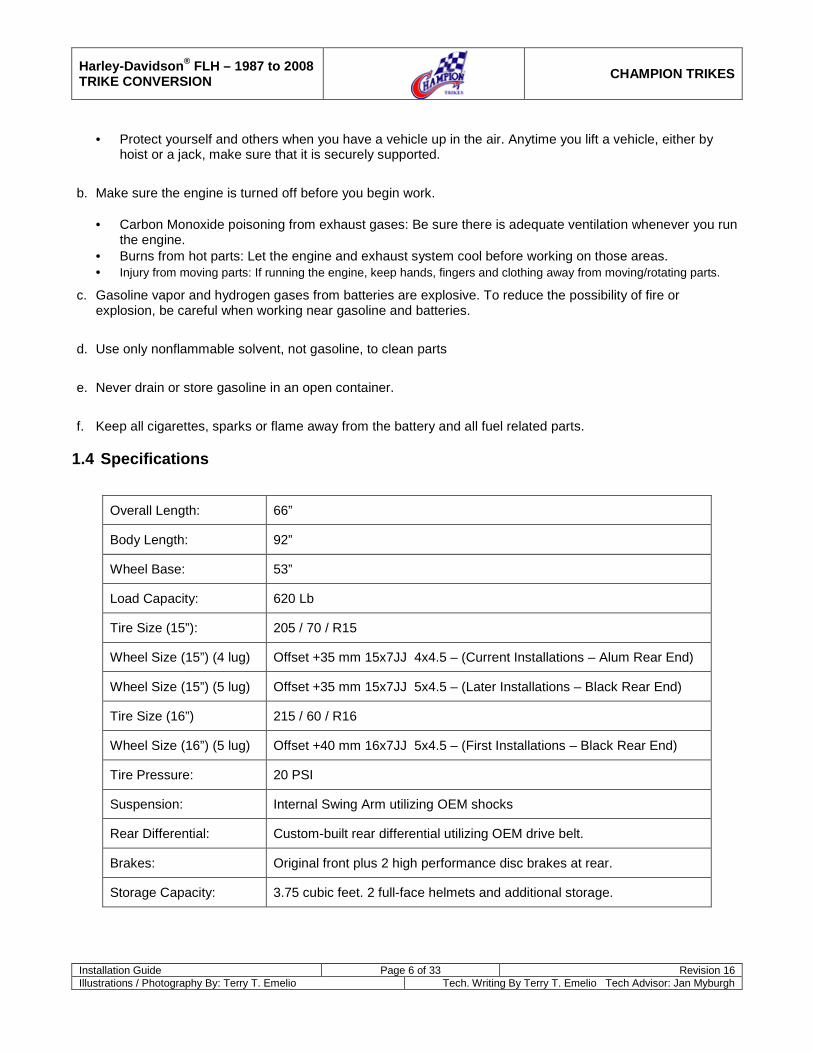
1.4 Specifications
Overall Length: 66”
Body Length: 92”
Wheel Base: 53”
Load Capacity: 620 Lb
Tire Size (15”): 205 / 70 / R15
Wheel Size (15”) (4 lug) Offset +35 mm 15x7JJ 4x4.5 – (Current Installations – Alum Rear End)
Wheel Size (15”) (5 lug) Offset +35 mm 15x7JJ 5x4.5 – (Later Installations – Black Rear End)
Tire Size (16”) 215 / 60 / R16
Wheel Size (16”) (5 lug) Offset +40 mm 16x7JJ 5x4.5 – (First Installations – Black Rear End)
Tire Pressure: 20 PSI
Suspension: Internal Swing Arm utilizing OEM shocks
Rear Differential: Custom-built rear differential utilizing OEM drive belt.
Brakes: Original front plus 2 high performance disc brakes at rear.
Storage Capacity: 3.75 cubic feet. 2 full-face helmets and additional storage.

Harley-Davidson® FLH – 1987 to 2008 TRIKE CONVERSION
CHAMPION TRIKES
Installation Guide Page 7 of 33 Revision 16 Illustrations / Photography By: Terry T. Emelio Tech. Writing By Terry T. Emelio Tech Advisor: Jan Myburgh
2 Removal of Original Parts
a. Disconnect the Battery.
b. Secure and raise motorcycle 9 to 10 inches using a quality motorcycle lift.
c. Remove the following from the vehicle. See OEM manual for detailed instructions. Items to be retained for re-installation after modification are noted.
· Fuel Tank –
o 1987 – 2007 Models: To be re-installed after installation of engine mount stiffeners. o 2008 Models : It is NOT necessary to remove fuel tank as stiffeners are not required.
· Seat - to be re-installed; without modification (1993 – 2008) / after modification (1987 – 1992)
· Left and right side covers - to be re-installed after modification. (Right side cover supplied by Champion
Sidecars 1987 – 1992 Models)
· Tour Box - to be re-installed without modification.
· Left and right saddle bags.
· Left and right rear crash bars, saddlebag rails.
· Tour Box mounting frame.
· Left and right passenger foot rests - to be re-installed without modification.
· Left and right mufflers
· Rear wheel NOTE: Prior to removing rear wheel, depress foot brake and secure in down position (e.g., zip-tie to floor board). This will prevent fluid flow when rear brake Caliper is removed.
· Remove Rear Caliper (disconnect brake line at Caliper).
NOTE: Cap line to prevent introduction of dust / debris into line. Remove Caliper.
· Rear drive pulley: 1987-2003 to be re-installed without modification. 2004-2008 use Champion supplied pulley.
· Rear Fender
· Swing Arm
· 1987 – 1992 Models: Purchase 1995 FLH Seat Hand Rail, HD Part No. 91583-97 (Not furnished by Champion Sidecars).

Harley-Davidson® FLH – 1987 to 2008 TRIKE CONVERSION
CHAMPION TRIKES
Installation Guide Page 8 of 33 Revision 16 Illustrations / Photography By: Terry T. Emelio Tech. Writing By Terry T. Emelio Tech Advisor: Jan Myburgh
3 Installation of Trike Conversion Kit
3.1 Remove Pivot Assemblies from OEM Swing Arm.
3.1.1 1987 – 2001 Models
a. Pry the spacer and plastic retaining ring from one side of the swing arm.
b. Place the swing arm in an arbor or hydraulic press. Place the press collar (Swing Arm Assembly Tool, Part No. HD-96200-80) on the outside diameter of the swing arm. Figure 1
c. Using a long extension and socket, press the clevebloc out of the swing arm.
d. NOTE: The clevebloc is a fluid filled bushing. ALWAYS press on the clevebloc outer sleeve.
e. Repeat above steps for opposite end of swing arm. 3.1.2 2002 - 2008
a. See OEM manual for pivot assembly removal instructions, noting use of HD special tools. Keep the bearings - to be installed later.
b. Modify Outer Spacers
· Machine or drill outer spacers to match large (¾”) bore as shown. Figure 2
· Ensure spacers slide freely over full length of pivot shaft.
3.2 Install Pivot Assemblies to Champion Swing Arm
3.2.1 1987 – 2001 Models
a. Place a new
b. NOTE: It is strongly recommended that NEW tolerance rings and clevebloc’s be used when installing pivot components to Champion Swing Arm. Using the PRESS PLUG, press the spacer, plastic ring and clevebloc into one side of the Swing Arm. Insure that the stepped surface of the clevebloc is flush with the outer surface of the Champion Swing Arm.
tolerance ring on a clevebloc.
Figure 3
c. Repeat above steps for opposite end of Swing Arm.
OEM Swing Arm Pivot Assembly
Figure 1
Before After Figure 2
Flush
Figure 3

Harley-Davidson® FLH – 1987 to 2008 TRIKE CONVERSION
CHAMPION TRIKES
Installation Guide Page 9 of 33 Revision 16 Illustrations / Photography By: Terry T. Emelio Tech. Writing By Terry T. Emelio Tech Advisor: Jan Myburgh
3.2.2 2002 - 2008
a. Install OEM pivot bearings to Swing Arm, from outside, inwards. Figure 4
CAUTION: When installing bearing, always press on outer race.
b. Install inner spacer to Swing Arm, from outside, inwards (opposite of OEM installation). Figure 4
c. Install modified outer spacer to Swing Arm, from inside, outwards (opposite of OEM installation). Figure 4
3.3 Installing Champion Swing Arm to Vehicle (All Models)
NOTE: 1993 to 2001 Models- If the Swing Arm does not fit over the transmission boss, check that the clevebloc’s are approximately 4-9/16” apart.
a. Coat OE pivot shaft with Loctite ANTI-SEIZE.
b. Position Champion Swing Arm (with brake line T-Block screw on cross bar pointing upward) to rear of transmission. Figure 5
3.3.1 1999 And Earlier Models
a. Install rubber mount to pivot shaft, small diameter of boss facing outward with the slot at top.
b. From left side of vehicle, install pivot shaft through Champion Swing Arm and transmission mount.
c. From right side of vehicle, install rubber mount, washer and nut to pivot shaft. Leave nut lose enough to allow rubber mounts to rotate.
d. Install left and right Swing Arm brackets. Ensure rubber mount index tabs fully engage bracket slots. Hand tight mounting bolts.
e. Torque pivot bolt nut to 45 lbs. ft.
f. Remove left and right Swing Arm brackets
g. Install supplied white stabilizer bushings on both sides pivot shaft nuts, using small amount of grease, making sure to align of center hole with pivot shaft and nut. Figure 6, Figure 7 & Figure 8
h. Re-install left and right Swing Arm brackets. Ensure rubber mount index tabs fully engage bracket slots. Torque mounting bolts to 34-42 ft. lbs.
Figure 4
Figure 5
Figure 6
Figure 7
Brake Line T-Block Screw

Harley-Davidson® FLH – 1987 to 2008 TRIKE CONVERSION
CHAMPION TRIKES
Installation Guide Page 10 of 33 Revision 16 Illustrations / Photography By: Terry T. Emelio Tech. Writing By Terry T. Emelio Tech Advisor: Jan Myburgh
3.3.2 2000 to 2008 Models
a. Install pivot shaft through swing-arm and transmission.
b. Install rubber mounts to left and right ends of shaft (flat side to swing arm).
c. Install left and right swing-arm brackets. Ensure bracket index tabs fully engage bracket slots. Snug down mounting bolts.
d. Install OEM spacers and lock nuts to pivot shaft ends. Hold right side nut and torque left side to 45 lbs. ft. Hold left side and torque right side to 45 lbs. ft. Figure 9
e. Remove left swing-arm bracket.
f. Install supplied steel bushing into rubber mount and over shaft spacer and nut (shoulder in bushing hole inboard). Figure 10
g. Install urethane bushing to shaft end. Figure 10
h. Re-install left swing-arm bracket. Ensure bracket index tab fully engages bracket slot. Torque bracket bolts to 34-42 lbs. ft. Figure 11
i. Remove right swing-arm bracket.
j. Repeat steps f and g for right side pivot.
k. Re-install right swing-arm bracket. Ensure index tab fully engages bracket slot. Torque bracket bolts to 34-42 lbs. ft.
Figure 8
Figure 9
Figure 10
Figure 11

Harley-Davidson® FLH – 1987 to 2008 TRIKE CONVERSION
CHAMPION TRIKES
Installation Guide Page 11 of 33 Revision 16 Illustrations / Photography By: Terry T. Emelio Tech. Writing By Terry T. Emelio Tech Advisor: Jan Myburgh
3.4 Installing Drive Pulley (Aluminum Rear End Assembly)
CAUTION: Do not use air driven impact tools to assemble the Champion Aluminum Rear End Assembly. NOTE: Use only the Champion supplied hardware when installing drive pulley to differential.
NOTE: 2004-2008 models use a CS supplied narrow Sprocket (Can also use HD Heavy Duty belt and wide sprocket).
a. Remove the three ¾” bolts securing the left half of the rear end assembly to the connector tubes. Figure 12
b. Separate the two halves of the rear end assembly, leaving the differential on the right half. Figure 12
c. Install pulley to differential using the supplied hardware and red Loctite. Figure 13
2000 - 2003 Models: Install supplied Sprocket Adapter to differential prior to installation of rear pulley.
d. Torque bolts to 55 ft. lbs.
e. Install carrier bearing to differential. Ensure bearing is properly and fully seated on the differential. Figure 14
f. Reunite the left and right halves of the differential assembly. Ensure proper engagement of the axle into the differential and that the carrier bearing is true in the bearing flange of the left axle assembly. Figure 15
g. Re-install the three ¾” bolts, flat washers and split washers. Snug but do not tighten hardware as adjustments will be made later. Figure 15
Figure 12
Figure 13
Figure 14
Figure 15
Connector tube

Harley-Davidson® FLH – 1987 to 2008 TRIKE CONVERSION
CHAMPION TRIKES
Installation Guide Page 12 of 33 Revision 16 Illustrations / Photography By: Terry T. Emelio Tech. Writing By Terry T. Emelio Tech Advisor: Jan Myburgh
3.5 Installing Aluminum Rear End Assembly to Swing Arm
a. Install the supplied M10 Adjuster Bolts and Jam Nuts to Adjuster Plates (one bolt and nut per plate). Figure 16
b. Install adjuster plates to the rear end assembly using the supplied hardware. Install plates to the rear end with the adjuster bolt to the outboard side. Snug but do not tighten hardware as adjustments will be made later. Figure 17
Qty per
side Description
4 3/8”-24 x 2-1/2”L socket head cap screw (no washer on head)
4 3/8”SAE flat washers 4 3/8”-24 NyLoc nuts
1996 and Previous Models-
c. Passing the left end through the drive belt, install the rear end assembly (with adjuster plates) to the swing arm using the supplied hardware. Snug but do not tighten hardware as adjustments will be made later. Figure 18 & Figure 19
Qty per
side Description
4 3/8”-24 x 1-1/2” hex head bolt 8 3/8” flat washers 4 3/8”-24 NyLoc nuts
1997 to 2008 Models- § Install one Spacer Block (see illustration below) between the
left and right adjuster plates and the swing arm using the supplied hardware listed below.
§
Qty per side Description
4 3/8”-24 x 2-1/4” hex head bolt 8 3/8” flat washers 4 3/8”-24 NyLoc nuts
Figure 16
Figure 17
(view of left side from rear)
Figure 18
Figure 19
Adjuster bolt to outboard side

Harley-Davidson® FLH – 1987 to 2008 TRIKE CONVERSION
CHAMPION TRIKES
Installation Guide Page 13 of 33 Revision 16 Illustrations / Photography By: Terry T. Emelio Tech. Writing By Terry T. Emelio Tech Advisor: Jan Myburgh
d. Remove the upper and lower rear connector tubes and position drive belt onto the rear pulley. Figure 20
e. Reinstall the upper and lower rear connector tubes. Apply 2-3 drops of oil to the connector tube bolts, install and torque to 150 lb. ft. Figure 21
f. Remove the lower front connector tube bolts, apply 2-3 drops of oil to the bolts, re-install and torque to 150 lb. ft. Figure 22
Figure 20
Figure 21
Figure 22

Harley-Davidson® FLH – 1987 to 2008 TRIKE CONVERSION
CHAMPION TRIKES
Installation Guide Page 14 of 33 Revision 16 Illustrations / Photography By: Terry T. Emelio Tech. Writing By Terry T. Emelio Tech Advisor: Jan Myburgh
3.6 Install Drive Pulley to Differential
a. Remove the two 3/4” x 1 1/2” L Socket Head Cap Screws (5/8” Allen wrench) from the Bullhorns connecting the left side of the Axle Housing to the right. Figure 23
b. Separate the left side Axle Housing from the right, leaving the differential attached to the right side assembly. Figure 24
c. 2000 - 2003 Models: Install Sprocket Adapter to differential. Figure 24
d. Install rear drive pulley to CS. supplied Rear Differential using supplied five 7/16” Hex Bolts and five 7/16” Flat Washers. Apply RED Loctite to bolts. Figure 25
NOTE: Use only the Champion supplied hardware when installing drive pulley to differential.
e. Torque bolts to 55 ft. lbs. NOTE: 2004 Up models use a CS supplied narrow Sprocket (Can also use HD Heavy Duty belt and wide sprocket).
Figure 23
Figure 24
Figure 25
Note: 2004 to 2008 model kits are shipped with the drive pulley preinstalled. It is only necessary to loosen the two ¾” bolts (Figure 23) and rotate the “horns” to slip the drive belt in. Replace the two ¾” bolts and install the complete Rear End to the swing arm using the instructions below for the attachment of the Rear End to the adjustment plates.
“Bull Horns”
Remove bolts
Harley-Davidson® FLH – 1987 to 2008 TRIKE CONVERSION
CHAMPION TRIKES
Installation Guide Page 15 of 33 Revision 16 Illustrations / Photography By: Terry T. Emelio Tech. Writing By Terry T. Emelio Tech Advisor: Jan Myburgh
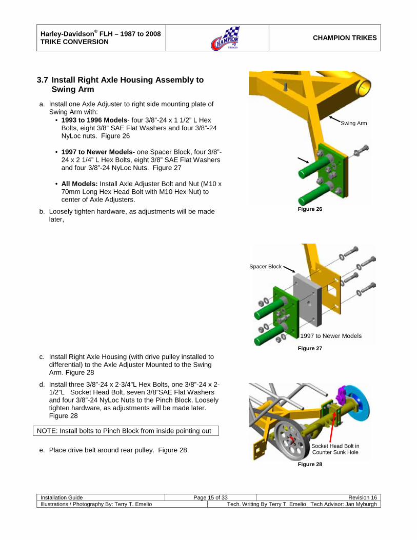
3.7 Install Right Axle Housing Assembly to Swing Arm
a. Install one Axle Adjuster to right side mounting plate of Swing Arm with:
· 1993 to 1996 Models- four 3/8”-24 x 1 1/2” L Hex Bolts, eight 3/8” SAE Flat Washers and four 3/8”-24 NyLoc nuts. Figure 26
· 1997 to Newer Models- one Spacer Block, four 3/8”-
24 x 2 1/4” L Hex Bolts, eight 3/8” SAE Flat Washers and four 3/8”-24 NyLoc Nuts. Figure 27
· All Models: Install Axle Adjuster Bolt and Nut (M10 x
70mm Long Hex Head Bolt with M10 Hex Nut) to center of Axle Adjusters.
b. Loosely tighten hardware, as adjustments will be made later,
c. Install Right Axle Housing (with drive pulley installed to differential) to the Axle Adjuster Mounted to the Swing Arm. Figure 28
d. Install three 3/8”-24 x 2-3/4”L Hex Bolts, one 3/8”-24 x 2-1/2”L Socket Head Bolt, seven 3/8”SAE Flat Washers and four 3/8”-24 NyLoc Nuts to the Pinch Block. Loosely tighten hardware, as adjustments will be made later. Figure 28
NOTE: Install bolts to Pinch Block from inside pointing out
e. Place drive belt around rear pulley. Figure 28
Figure 26
Figure 27
Figure 28
Swing Arm
Socket Head Bolt in Counter Sunk Hole
Spacer Block
1997 to Newer Models
Harley-Davidson® FLH – 1987 to 2008 TRIKE CONVERSION
CHAMPION TRIKES
Installation Guide Page 16 of 33 Revision 16 Illustrations / Photography By: Terry T. Emelio Tech. Writing By Terry T. Emelio Tech Advisor: Jan Myburgh
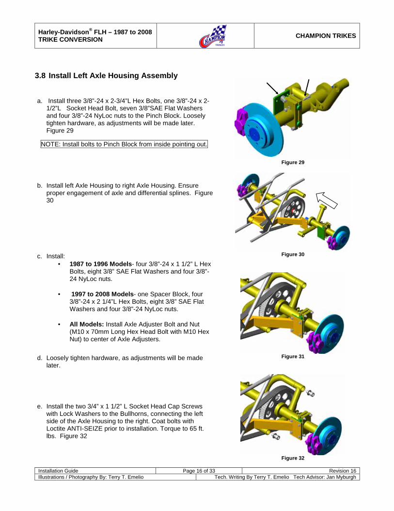
3.8 Install Left Axle Housing Assembly
a. Install three 3/8”-24 x 2-3/4”L Hex Bolts, one 3/8”-24 x 2-1/2”L Socket Head Bolt, seven 3/8”SAE Flat Washers and four 3/8”-24 NyLoc nuts to the Pinch Block. Loosely tighten hardware, as adjustments will be made later. Figure 29
NOTE: Install bolts to Pinch Block from inside pointing out.
b. Install left Axle Housing to right Axle Housing. Ensure proper engagement of axle and differential splines. Figure 30
c. Install: · 1987 to 1996 Models- four 3/8”-24 x 1 1/2” L Hex
Bolts, eight 3/8” SAE Flat Washers and four 3/8”-24 NyLoc nuts.
· 1997 to 2008 Models- one Spacer Block, four
3/8”-24 x 2 1/4”L Hex Bolts, eight 3/8” SAE Flat Washers and four 3/8”-24 NyLoc nuts.
· All Models: Install Axle Adjuster Bolt and Nut
(M10 x 70mm Long Hex Head Bolt with M10 Hex Nut) to center of Axle Adjusters.
d. Loosely tighten hardware, as adjustments will be made later.
e. Install the two 3/4” x 1 1/2” L Socket Head Cap Screws with Lock Washers to the Bullhorns, connecting the left side of the Axle Housing to the right. Coat bolts with Loctite ANTI-SEIZE prior to installation. Torque to 65 ft. lbs. Figure 32
Figure 29
Figure 30
Figure 31
Figure 32

Harley-Davidson® FLH – 1987 to 2008 TRIKE CONVERSION
CHAMPION TRIKES
Installation Guide Page 17 of 33 Revision 16 Illustrations / Photography By: Terry T. Emelio Tech. Writing By Terry T. Emelio Tech Advisor: Jan Myburgh
3.9 Install Shock Mount and Seat Rail Mount to Vehicle Frame
3.9.1 1987 - 1996 Models
a. Install Shock Mount to vehicle frame. Use hardware as noted in illustration. Figure 33
Figure 33
b. Install Seat Rail Mount. Use hardware as noted in illustration. Figure 34
Figure 34
3/8-24 x 2-3/4” Hex Bolts Gr8 3/8” SAE Flat Washer
3/8’ ID Spacer* 3/8” SAE Flat Washer 3/8” SAE Flat Washer 3/8” SAE Flat Washer
3/8”-24 NyLoc Nut
*1987-1992: 1-1/ 8” Long Spacer *1993-1996: 1” Long Spacer
5/16”-18 x 1” Hex Bolts Gr5 5/16” SAE Flat Washer 5/16” SAE Flat Washer
5/16”-18 NyLoc Nut
Spacer
Shock Tower
Motorcycle Frame Plates
Seat Rail Mount
1993 -1996 5/16”-18 x 1 ¾” Hex Bolt 5/16” SAE Flat Washer
5/16” I.D. x 3/8” L Spacer 5/16” SAE Flat Washer
5/16”-18 Nyloc Nut
1987 - 1992 5/16”-18 x 1” Hex Bolt 5/16” SAE Flat Washer 5/16” SAE Flat Washer
5/16”-18 Nyloc Nut
1993 - 1996 ½”-20 x 2-3/4” Bolt Gr8
½” SAE Flat Washer (Outside) ½” SAE Flat Washer (Inside)
½”-20 Nyloc Nut
1987 - 1992 ½”-20 x 2-3/4” Bolt Gr8
One ½” SAE Flat Washer (Outside) One ½” SAE Flat Washer (Between
Frame and Shock Tower) One ½” SAE Flat Washer (Outside)
½”-20 Nyloc Nut ½” ID X ¾ OD x .22 Thk Spacer
Harley-Davidson® FLH – 1987 to 2008 TRIKE CONVERSION
CHAMPION TRIKES
Installation Guide Page 18 of 33 Revision 16 Illustrations / Photography By: Terry T. Emelio Tech. Writing By Terry T. Emelio Tech Advisor: Jan Myburgh
3.9.2 1997 – 2007
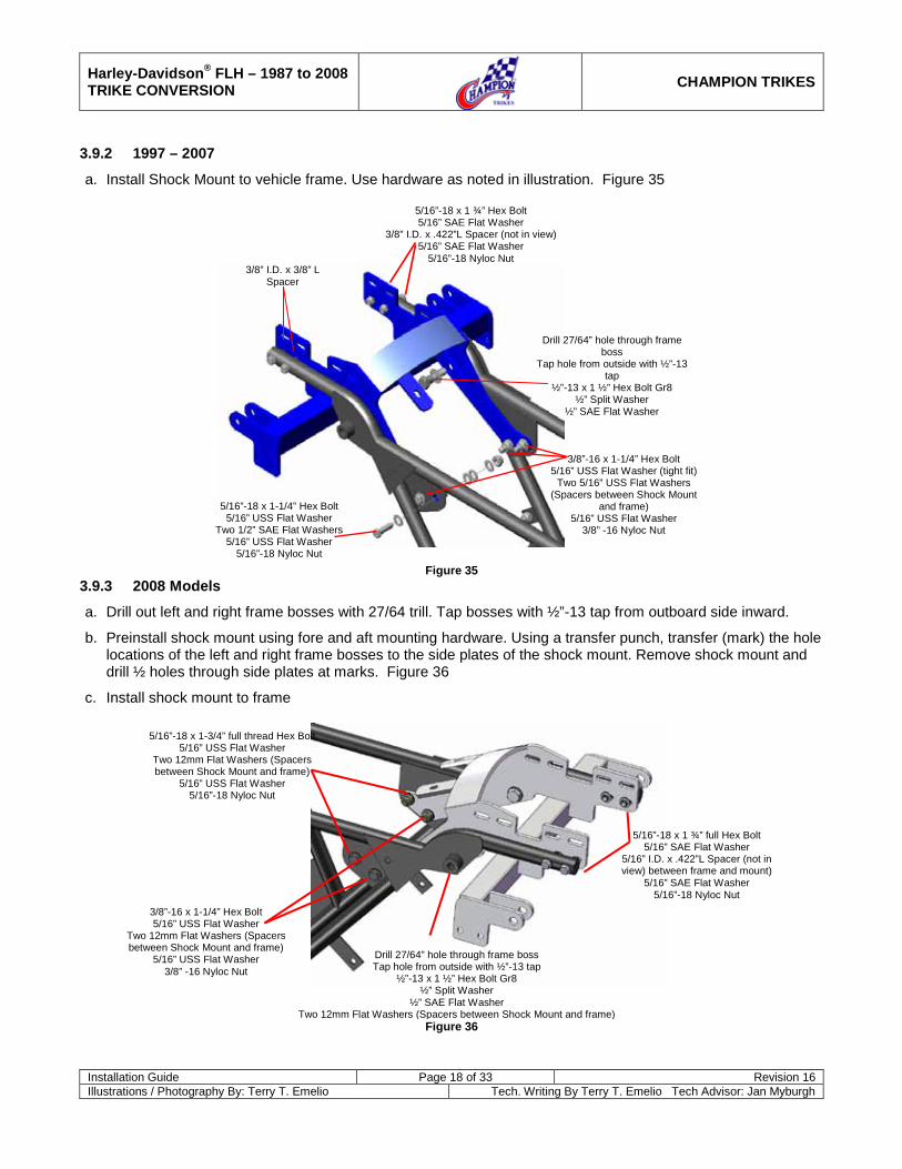
a. Install Shock Mount to vehicle frame. Use hardware as noted in illustration. Figure 35
Figure 35
3.9.3 2008 Models
a. Drill out left and right frame bosses with 27/64 trill. Tap bosses with ½”-13 tap from outboard side inward.
b. Preinstall shock mount using fore and aft mounting hardware. Using a transfer punch, transfer (mark) the hole locations of the left and right frame bosses to the side plates of the shock mount. Remove shock mount and drill ½ holes through side plates at marks. Figure 36
c. Install shock mount to frame
Figure 36
Drill 27/64” hole through frame boss Tap hole from outside with ½”-13 tap
½”-13 x 1 ½” Hex Bolt Gr8 ½” Split Washer
½” SAE Flat Washer Two 12mm Flat Washers (Spacers between Shock Mount and frame)
5/16”-18 x 1 ¾” full Hex Bolt 5/16” SAE Flat Washer
5/16” I.D. x .422”L Spacer (not in view) between frame and mount)
5/16” SAE Flat Washer 5/16”-18 Nyloc Nut
3/8”-16 x 1-1/4” Hex Bolt 5/16” USS Flat Washer
Two 12mm Flat Washers (Spacers between Shock Mount and frame)
5/16” USS Flat Washer 3/8” -16 Nyloc Nut
5/16”-18 x 1-3/4” full thread Hex Bolt 5/16” USS Flat Washer
Two 12mm Flat Washers (Spacers between Shock Mount and frame)
5/16” USS Flat Washer 5/16”-18 Nyloc Nut
Drill 27/64” hole through frame boss
Tap hole from outside with ½”-13 tap
½”-13 x 1 ½” Hex Bolt Gr8 ½” Split Washer
½” SAE Flat Washer
5/16”-18 x 1 ¾” Hex Bolt 5/16” SAE Flat Washer
3/8” I.D. x .422”L Spacer (not in view) 5/16” SAE Flat Washer
5/16”-18 Nyloc Nut 3/8” I.D. x 3/8” L
Spacer
3/8”-16 x 1-1/4” Hex Bolt 5/16” USS Flat Washer (tight fit)
Two 5/16” USS Flat Washers (Spacers between Shock Mount
and frame) 5/16” USS Flat Washer
3/8” -16 Nyloc Nut
5/16”-18 x 1-1/4” Hex Bolt 5/16” USS Flat Washer
Two 1/2” SAE Flat Washers 5/16” USS Flat Washer
5/16”-18 Nyloc Nut

Harley-Davidson® FLH – 1987 to 2008 TRIKE CONVERSION
CHAMPION TRIKES
Installation Guide Page 19 of 33 Revision 16 Illustrations / Photography By: Terry T. Emelio Tech. Writing By Terry T. Emelio Tech Advisor: Jan Myburgh
3.10 Install Champion Battery Tray (1987 – 1992 Models Only)
a. Set Champion Battery Tray into position over frame cross bar and Shock Mount. Figure 37
b. Align bolt hole of forward hanger with hole in frame cross bar. Mark hole position of rear hanger on Shock Mount.
c. Drill ¼” hole through Shock Mount.
d. Install Champion Battery Tray to vehicle and Shock Mount and using:
Front Hanger One ¼”-20 x 1” L Hex Bolt Two ¼” SAE Flat Washers One ¼” NyLoc Nut
Rear Hanger One ¼”-20 x2” L Hex Bolt Two ¼” SAE Flat Washers One ¼” NyLoc Nut
NOTE: For future removal of battery, removal of seat handrail and seat mounting bracket will be necessary.
3.11 Relocate Relays (1987 – 1992 Models Only)
a. Unscrew and the two remove relays from the outside of oil tank.
b. Relocate relays inside of frame structure and secure.
3.12 Install Body Frame to Vehicle
3.12.1 1987 to 1992 Only
a. Prior to installing Body Frame to vehicle, weld the included Body Frame hanger tab to vehicle frame as shown. New tab location should mirror OEM tab on left side of frame. Figure 38
Caution: Duplicate welds as on OEM tab. Do not
weld around circumference of frame tubing.
3.12.2 All Models
a. Install Body Frame Hanger Plates (slotted holes at top) to left and right ends of Shock Mount. Figure 39
Hardware: · Four 3/8"-24 x 1-1/2" Hex Bolts · Eight 3/8"-24 USS Flat Washers · Four 3/8" NyLoc nuts · Eight Star Lock Washers against metal parts.
Figure 37
Figure 38
Figure 39

Harley-Davidson® FLH – 1987 to 2008 TRIKE CONVERSION
CHAMPION TRIKES
Installation Guide Page 20 of 33 Revision 16 Illustrations / Photography By: Terry T. Emelio Tech. Writing By Terry T. Emelio Tech Advisor: Jan Myburgh
3.12.3 Install Body Frame to Hanger Plates -1987 to 1996 Models
Figure 40
3.12.4 Install Body Frame to Hanger Plates -1997 to 2008 Models
Figure 41
Outside: 3/8”-24 x 1-1/2” Hex Bolt
3/8” USS Flat Washer 3/8” Star Lock Washer
Inside: 3/8” Star Lock Washer 3/8” USS Flat Washer
3/8”-24 Nyloc Nut
Outside: 3/8”-24 x 1 ¼” Hex Bolt
3/8” Flat Washer Inside:
3/8” Flat Washer outside 3/8”-24 Nyloc Nut
Use Rear Bolt Hole Location
Outside: 3/8”-24 x 1-1/2” Hex Bolt
3/8” USS Flat Washer 3/8” Star Lock Washer
Inside: 3/8” Star Lock Washer 3/8” USS Flat Washer
3/8”-24 Nyloc Nut
Outside: 3/8”-24 x 1 ¼” Hex Bolt
3/8” Flat Washer Inside:
3/8” Flat Washer outside 3/8”-24 Nyloc Nut
Use Front Bolt Hole Location

Harley-Davidson® FLH – 1987 to 2008 TRIKE CONVERSION
CHAMPION TRIKES
Installation Guide Page 21 of 33 Revision 16 Illustrations / Photography By: Terry T. Emelio Tech. Writing By Terry T. Emelio Tech Advisor: Jan Myburgh
3.13 Install Shock Absorbers
a. Install OEM shock absorbers (air line fitting to rear) between rear end assembly and Shock Mount. Figure 42
b. Hardware:
c. Upper Shock Mounting bolts (per side) § 1/2"-20 x 2 3/4”L Hex Head Bolt Gr8 § 1/2" Flat Washer § Two 1/2" S.S. Flat Washers (between shock eye and
mount tab) § 1/2" Flat Washer § 1/2" NyLoc Nut
Lower Shock Mounting bolts (per side) § 1/2"-20 x 3" L Hex Head Bolt § Two 1/2" Flat Washers § 1/2" NyLoc Nut
NOTE: Install Shock Mounting bolts from inside
of frame, outward. This will facilitate future removal of shocks without removing the trike body
NOTE: Air fill valve will be installed to trunk of trike body inner liner in supplied hole
3.14 Aligning and Tensioning Rear Drive Pulley
The slots in the Swing Arm/Adjuster Mount plates allow approximately 3/8" lateral movement of the rear axle assembly. Approximately 1 1/4" fore and aft movement is accomplished by sliding the Axle Housing on the pins of the axle Adjuster plates.
a. Square axle Adjusters with Swing Arm mount plates and tighten hardware.
b. Set belt tension by moving axle assembly forward or rearward as necessary. Belt should have approximately 1-1/2” of total vertical movement. Tighten pinch block hardware.
c. Measure distance between forward face of pinch clamp and plate of axle Adjuster. Ensure left and right sides of Axle Housing are equal distant.
NOTE: Belt tension should be checked prior to final assembly (mounting body) of trike kit. Check with vehicle secure, on jack stands, engine running and transmission in gear. Note position and tension of belt while running. Stop engine and adjust accordingly.
Figure 42
Air fitting to rear

Harley-Davidson® FLH – 1987 to 2008 TRIKE CONVERSION
CHAMPION TRIKES
Installation Guide Page 22 of 33 Revision 16 Illustrations / Photography By: Terry T. Emelio Tech. Writing By Terry T. Emelio Tech Advisor: Jan Myburgh
3.15 Install Brake Lines
a. Install Braided Brake Lines to Calipers, with swivel fitting into caliper. Figure 43
b. Install T-Block to bolt at center cross brace of Swing Arm with 1/4" NyLoc Nut. Connect Brake Lines to T-Block. Figure 44
c. Connect OEM brake line from rear master cylinder to T-Block using 10mm single Banjo Bolt and two Crush Washers. Figure 44
d. Use supplied zip-ties to secure Braided Line to Swing Arm.
e. Using brake fluid as specified on the Master cylinder, bleed rear brake system.
o Toughly bleed system using the upper
3.16 Final Check of Drive Belt Tension
bleeders. Once complete, pressure bleed the system once at the lower bleeders.
a. Re-check and adjust belt tension and alignment as outlined in section 3.12. Feathering rear brakes during engine running check will help identify any problems with belt alignment and tracking on pulleys.
3.17 Install Mufflers and Tail Pipes
3.17.1 1999 & Down Model Years
a. Slide left and right CS Supplied Drop Down Tubes to OEM header pipe using OEM clamp to secure. Do not tighten at this time.
b. Install CS supplied muffler’s inlets to Drop Down Tubes using CS-supplied clamps. Figure 45
c. Install exhaust end of mufflers to the muffler mount tabs at rear of Body Frame. Install hardware as follows: Install 5/16"-18 x 2" L Hex Head Bolts and Flat Washers from top to bottom, 1 Rubber Spacer at top and bottom of muffler bracket, one Dome Washer under Rubber Spacer and one 5/16"-18 NyLoc nut. Figure 46
NOTE: Tighten NyLoc nuts until only 1 thread of bolt end is visible outside of nut. This is to allow the mufflers to move with engine vibration. DO NOT OVER-TIGHTEN NUTS.
Figure 43
Figure 44
Figure 45
Figure 46

Harley-Davidson® FLH – 1987 to 2008 TRIKE CONVERSION
CHAMPION TRIKES
Installation Guide Page 23 of 33 Revision 16 Illustrations / Photography By: Terry T. Emelio Tech. Writing By Terry T. Emelio Tech Advisor: Jan Myburgh
3.17.2 2000 to 2008 model Years Note: 2000 & up models utilize the OEM mufflers.
a. Cut 2-3/8” from the end of the right side (RHS) OEM exhaust pipe. The left hand side (LHS) OEM exhaust may also have to be cut to align it properly – cut in ¼” increments until it aligns correctly.
b. Install muffler hangers to body frame as shown using supplied hardware. Do not over tighten bolts to over compress rubber vibration rubbers (only two threads exposed). Figure 47 & Figure 48
Figure 47
c. Install OEM mufflers to hangers using the supplied (four) 5/16-18 x ¾ long bolts and (four) 5/16 split washers. Do not tighten at this time. Figure 49
d. Install left (Figure 50) and right (Figure 51) exhaust extension tubes between mufflers and exhaust pipes using the OEM and supplied clamps as shown.
e. Ensure proper alignment / connection of exhaust tubes extensions and mufflers.
f. Tighten clamps and muffler mounting bolts.
Figure 48
Figure 49
Figure 50
Figure 51

Harley-Davidson® FLH – 1987 to 2008 TRIKE CONVERSION
CHAMPION TRIKES
Installation Guide Page 24 of 33 Revision 16 Illustrations / Photography By: Terry T. Emelio Tech. Writing By Terry T. Emelio Tech Advisor: Jan Myburgh
3.18 Install Trike Body to Vehicle
Note: The installation/alignment of the body is an iterative process to find the correct position of body in relation to the wheels The four holes already in the body are primarily for shipping purposes. These holes might line up with the pre-drilled body frame holes when the body is fitted. Follow instructions below to re-drill holes if required.
a. Place trike body into position over vehicle and onto Body Frame. Figure 52
b. Locate the four holes pre drilled into trike body and install one 3/8"-24 x 1-1/4" L and one 3/8"–1 ½” Fender Washer from inside of body at each hole. Install 3/8" SAE Flat Washer and 3/8”-24 NyLoc nut to each bolt.
c. Locate left and right center body mount tabs. Drill a 3/8" hole up through tab and body (tab is predrilled) Install bolts
d. Connect trike wire loom to OEM tail light harness connector. § (1987-1992). Requires use of CS-supplied harness
adapter. Ground: Black
§ (1993-1996) Connect accessory blue wire (single wire) to
12V power source on vehicle. § (1997-2008) Requires use of CS-supplied harness adapter.
Do not connect blue wire (single wire) to accessory.
e. Install wheels.
3.19 Install Tour Box Frame
3.19.1 1997-2005
a. Install Tour Box frame to Shock Mount with the eight 3/8"-24 x 1-1/4" L Hex Head Bolts, sixteen 3/8" SAE Flat Washers, eight 3/8"-24 NyLoc nuts. Figure 53
3.19.2 2006-2008 Note: PRIOR to installing tour box frame, modification to tour box must be made. See step
a. Requires the supplied spacer plates to be installed between the tour box frame and the shock mount (both sides). Figure 54
Figure 52
Figure 53
Figure 54
Spacer block

Harley-Davidson® FLH – 1987 to 2008 TRIKE CONVERSION
CHAMPION TRIKES
Installation Guide Page 25 of 33 Revision 16 Illustrations / Photography By: Terry T. Emelio Tech. Writing By Terry T. Emelio Tech Advisor: Jan Myburgh
3.19.3 1997-2005
a. Use four ¼ x 7/8 Hex Head Bolts and1/4 Flat washers .Use holes in galvanized steel plate as guide and drill new 5/16 holes, using forward set of holes. This moves the tour box back. Figure 55
3.19.4 Install Seat Rail (1991-1996 only)
a. Install seat rail to tour box frame and Seat Rail Mount as shown. Figure 56
3.20 Install Tour Box
3.20.1 1987-1996
a. Install tour box to tour box frame with OEM hardware.
3.20.2 2006- 2008
a. Center the tour box frame to the bottom of the tour box with the rear cross brace of the frame in the rear groove of the tour box.
b. Mark the mounting hole locations of the frame to the box and drill a 5/16 hole through each mark.
c. Install tour box frame to shock mount (see step 3.17.2)
d. Install box to frame with supplied hardware (four ¼” x 7/8 hex head bolts and washers). Install with bolt head inside tour box.
3.21 Modify Side Covers
3.21.1 1987 to 1992 Models NOTE: Edge trim can be reused if desired. NOTE: Remove rubber trim and grommet from OEM right side-cover and install to side-cover supplied by Champion Sidecars
a. Carefully remove rubber trim from rear section of side covers.
b. Cut in area shown above to allow clearance for the trike Body Frame. Figure 57 (next page)
c. Check side cover fit to motorcycle with attention to fit around trike Body Frame. Trim as necessary.
d. Replace edge trim with appropriate glue (e.g., super glue).
e. Install covers to motorcycle.
Figure 55
Figure 56
Two ¼"-7/8" L Hex Bolts Four ¼" Flat Washers Two ¼" NyLoc Nuts
Four 5/16"-18 x 1" L Hex Bolt Eight 5/16" SAE Flat Washers
Four 5/16"-18 NyLoc Nuts

Harley-Davidson® FLH – 1987 to 2008 TRIKE CONVERSION
CHAMPION TRIKES
Installation Guide Page 26 of 33 Revision 16 Illustrations / Photography By: Terry T. Emelio Tech. Writing By Terry T. Emelio Tech Advisor: Jan Myburgh
Figure 57
3.21.2 1993 to 1996 Models
Figure 58
a. Carefully remove rubber trim from rear section of side covers.
b. Mark side cover as shown (Figure 58). End of line at top, should be approximately ½" behind mounting tab.
c. Cut covers along mark.
d. Check side cover fit to motorcycle with attention to fit around trike Body Frame. Trim as necessary.
e. Replace edge trim with appropriate glue (e.g., super glue).
f. Install covers to motorcycle.

Harley-Davidson® FLH – 1987 to 2008 TRIKE CONVERSION
CHAMPION TRIKES
Installation Guide Page 27 of 33 Revision 16 Illustrations / Photography By: Terry T. Emelio Tech. Writing By Terry T. Emelio Tech Advisor: Jan Myburgh
3.21.3 1997 to 2008 Models
Figure 59
a. Carefully remove rubber trim from rear section of side covers.
b. Cut in area shown above to allow clearance for the trike Body Frame. Figure 59
c. Check side cover fit to motorcycle with attention to fit around trike Body Frame. Trim as necessary.
d. Replace edge trim with appropriate glue (e.g., super glue).
e. Install covers to motorcycle.
3.22 Install Seat Mount Adapter To Seat - 1987 – 1992 Only
a. Loosely install seat mount adapter to tour box mount.
b. Position and align seat to vehicle.
c. Note and mark location and position seat over seat mount adapter. Figure 60
d. Remove seat from vehicle and drill 3/16” holes and install seat mount adapter to seat using supplied 3/16” rivets
e. Install seat to vehicle.
Figure 60

Harley-Davidson® FLH – 1987 to 2008 TRIKE CONVERSION
CHAMPION TRIKES
Installation Guide Page 28 of 33 Revision 16 Illustrations / Photography By: Terry T. Emelio Tech. Writing By Terry T. Emelio Tech Advisor: Jan Myburgh
4 Install Frame Stiffeners to Vehicle
Frame
4.1 1987 – 2002 Models (CH-F01-011)
Vibration Damper with Rod Ends supplied by Champion Sidecars. Figure 61
a. Prepare Mounting Surfaces
· Remove fuel tank (If not already removed).
· Remove the adjuster rod securing the engine to the frame.
· Position frame stiffener plates as shown.
· Mark frame around plates. Figure 62
· Mark (scribe) drill location of strut rod-end hole though OE bracket to left hand stiffener tab. Figure 60 (arrow)
· Remove left hand stiffener plate and mark (scribe) drill location of strut rod-end hole though OE bracket to right hand stiffener tab. Figure 63 (arrow)
· Drill 3/8” hole through each stiffener plate at locations marked..
· Sand the area of the frame inside of marks to remove all paint and roughen surface. Figure 64
· Coarse sand the inboard faces of the stiffener plates.
b. Bond Plates to Frame
· Install stiffener plates to vehicle frame with strut and hardware to check fit of parts. Plates must lay flush against frame. Bend stiffener plate tabs as necessary to ensure flush fit.
· Thoroughly mix contents of Champion supplied epoxy tubes.
· Apply mixture to sanded surface of frame and unpainted surfaces of stiffener plates.
· Position plates to frame and install and tighten 3/8" nut and bolt to secure plate tabs to frame tab.
· Clamp plates to frame.
· Allow at least 8 hours to dry.
Figure 61
Figure 62
Figure 63
Figure 64

Harley-Davidson® FLH – 1987 to 2008 TRIKE CONVERSION
CHAMPION TRIKES
Installation Guide Page 29 of 33 Revision 16 Illustrations / Photography By: Terry T. Emelio Tech. Writing By Terry T. Emelio Tech Advisor: Jan Myburgh
c. Install Engine Mount and Hardware.
· Set new engine mount rod assembly to length of OEM rod assembly.
· Install engine mount to frame tab with supplied 3/8"-
16 x 2 1/4" Button Head Allen Screws, three 5/16" USS Flat Washers and one 3/8"-16 NyLoc nut as shown. Figure 65
· Install engine mount to engine bracket with supplied
3/8"-24 x 2" L Hex Head Bolt, four 5/16" USS Flat Washers and one 3/8"-24 NyLoc nut as shown. Figure 66
4.2 2003 – 2007 Models (CH-F01-037)
a. Pre-installation
· Remove the fuel tank and top of the wire cover over the frame spine. Remove OEM adjuster strut. Position the right side stiffener tab (Figure 67) onto frame (between frame and plastic) and mark its general position on the plastic wire loom channel.
· Remove stiffener plate and trim the channel. Only
the portion of the cover that contacts the frame need be removed. Figure 68
· Re-position and clamp the right side stiffener tab
onto frame.
· Plate must lay flush against frame and OEM tab. If necessary, bend stiffener plate to ensure flush fit and reinstall to frame.
NOTE: Do not alter the OEM frame tabs.
· Mark (scribe) drill location of strut rod-end hole though OE bracket to right hand stiffener tab. Figure 69
· Mark the frame around the stiffener tab where it
contacts the frame. Remove stiffener plate. Figure 69
Figure 65
Figure 66
Figure 67
FRONT
Figure 68
Figure 69
Harley-Davidson® FLH – 1987 to 2008 TRIKE CONVERSION
CHAMPION TRIKES
Installation Guide Page 30 of 33 Revision 16 Illustrations / Photography By: Terry T. Emelio Tech. Writing By Terry T. Emelio Tech Advisor: Jan Myburgh
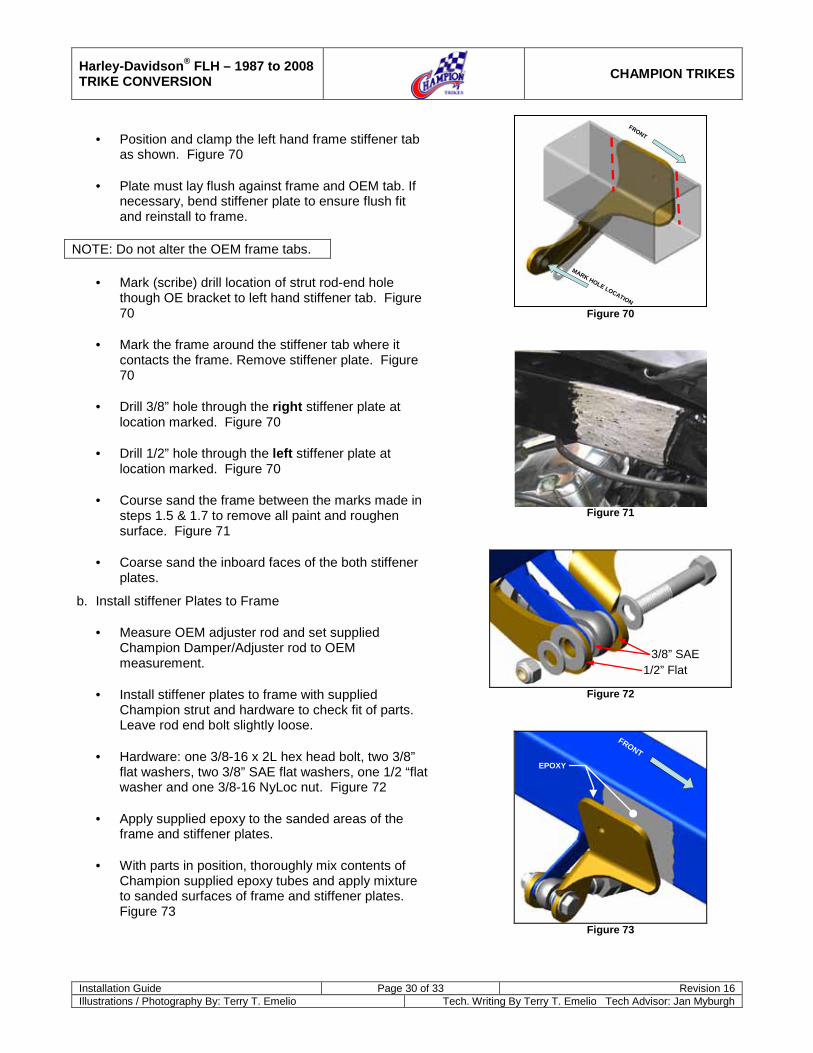
· Position and clamp the left hand frame stiffener tab
as shown. Figure 70 · Plate must lay flush against frame and OEM tab. If
necessary, bend stiffener plate to ensure flush fit and reinstall to frame.
NOTE: Do not alter the OEM frame tabs.
· Mark (scribe) drill location of strut rod-end hole though OE bracket to left hand stiffener tab. Figure 70
· Mark the frame around the stiffener tab where it
contacts the frame. Remove stiffener plate. Figure 70
· Drill 3/8” hole through the right stiffener plate at
location marked. Figure 70 · Drill 1/2” hole through the left stiffener plate at
location marked. Figure 70 · Course sand the frame between the marks made in
steps 1.5 & 1.7 to remove all paint and roughen surface. Figure 71
· Coarse sand the inboard faces of the both stiffener
plates.
b. Install stiffener Plates to Frame
· Measure OEM adjuster rod and set supplied Champion Damper/Adjuster rod to OEM measurement.
· Install stiffener plates to frame with supplied
Champion strut and hardware to check fit of parts. Leave rod end bolt slightly loose.
· Hardware: one 3/8-16 x 2L hex head bolt, two 3/8”
flat washers, two 3/8” SAE flat washers, one 1/2 “flat washer and one 3/8-16 NyLoc nut. Figure 72
· Apply supplied epoxy to the sanded areas of the
frame and stiffener plates.
· With parts in position, thoroughly mix contents of Champion supplied epoxy tubes and apply mixture to sanded surfaces of frame and stiffener plates. Figure 73
Figure 70
Figure 71
3/8” SAE1/2” Flat
Figure 72
FRONT
EPOXY
Figure 73
FRONT
MARK HOLE LOCATION

Harley-Davidson® FLH – 1987 to 2008 TRIKE CONVERSION
CHAMPION TRIKES
Installation Guide Page 31 of 33 Revision 16 Illustrations / Photography By: Terry T. Emelio Tech. Writing By Terry T. Emelio Tech Advisor: Jan Myburgh
· Clamp stiffener plates to frame and tighten rod end
bolt. Figure 74
· From left to right side, drill hole through frame as shown. Figure 75
· Install supplied 1/4-20 x 3-1/2”L countersunk screw
and 1/4-20 NyLoc nut through stiffener plates and frame. Securely tighten. Figure 76
c. Install Engine Mount and Hardware.
· Let assembly stand (clamp in place) and allow at least 8 hours drying.
· When dried, remove clamp and loosen bolt securing
adjuster rod to installed stiffener plates
· Secure adjuster rod to engine mounting bracket with the supplied 3/8"-16 x 1-3/4" L Hex Head Bolt, two 3/8” Flat Washers, OEM spacer and one 3/8"-16 NyLoc nut as shown. Figure 77
· Tighten all hardware.
4.3 2008 Models
a. Use only the vibration mount and rod ends supplied by Champion to replace the OEM engine mount using the OEM bolts and nuts
FRONT
CLAMP
TIGHT
Figure 74
Figure 75
Figure 76
OEM Spacer
Figure 77
DRILL L
FRONT

Harley-Davidson® FLH – 1987 to 2008 TRIKE CONVERSION
CHAMPION TRIKES
Installation Guide Page 32 of 33 Revision 16 Illustrations / Photography By: Terry T. Emelio Tech. Writing By Terry T. Emelio Tech Advisor: Jan Myburgh
5 Radio / CB Relocation (Rear Mounted Units)
For under-trunk mounted Radios and/or CB units.
5.1 Install Radio Mount Tabs
5.1.1 1993 – 1996 Models Only
a. Mount radio tabs to OEM radio using OEM hardware. Figure 78
b. Position radio assembly (wire connections to front)) to top of shock tower frame cross bar
c. Center assembly on cross bar and mark holes and drill ¼" holes. Figure 79
d. Install two ¼"-20 x 2" L Hex Bolts, four ¼" SAE Flat Washers and two ¼-20 NyLoc nuts to radio mount tabs and tighten.
6 Trailer Hitch Receiver (Optional)
6.1 Install Trailer Hitch Receiver
a. Install hitch receiver to trike Body Frame with supplied eight 5/16"-18 x 1" L Hex Bolts and 5/16” SAE Flat Washers. Figure 80
b. Electrical connectors not supplied. Mounting tab for connector socket is located on hitch receiver.
c. Color code for wiring as follows: (Confirm by testing)
Old Harness
New Universal Harness
(From Mid 2007)
Running lights Confirm by testing BROWN
Brake lights RED RED Turn signal,
right GREEN GREEN
Turn signal, left YELLOW YELLOW
Accessory BLUE BLUE
Ground Confirm by testing (BLACK or White) BLACK
Figure 78
Figure 79
Figure 80

Harley-Davidson® FLH – 1987 to 2008 TRIKE CONVERSION
CHAMPION TRIKES
Installation Guide Page 33 of 33 Revision 16 Illustrations / Photography By: Terry T. Emelio Tech. Writing By Terry T. Emelio Tech Advisor: Jan Myburgh
7 Hardware
FLH 87-96 TRIKE HARDWARE KIT PART #: HWK-F00-001
Qty Part Number Description A. ADJUSTMENT PLATES TO REAR END
2 HW-375-060 3/8-24x2-1/2 shcs 6 HW-375-056 3/8-24x2-3/4 hhcs gr8 8 HW-375-006 3/8-24x1-1/2 hhcs gr8
16 HW-375-011 3/8-24 nylock nut 30 HW-375-016 3/8 sae f/w
2 HW-M10-001 M10x1.25x70 hhcs full thread
2 HW-M10-009 M10x1.25 hex nut B. SHOCK TOWER MOUNTS TO BODY FRAME
2 HW-500-003 1/2-20x2 3/4 hhcs gr8 2 HW-375-056 3/8-24x2 3/4 hhcs gr8 4 ?? 5/16-18x1 3/4 hhcs gr8 2 HW-500-013 1/2-20 nylock nut 2 HW-375-011 3/8-24 nylock nut 4 HW-312-009 5/16-18 nylock nut 4 HW-500-020 1/2 sae f/w 8 HW-375-016 3/8 sae f/w 8 HW-312-017 5/16 sae f/w
C. BODY FRAME TO BIKE 8 HW-375-006 3/8-24x1 1/2 hhcs gr8 2 HW-375-043 3/8-24x1 1/4 hhcs gr8
20 HW-375-016 3/8 sae f/w 10 HW-375-011 3/8-24 nylock nut
16 HW-375-050 3/8 combination tooth lock washer
1 HW-250-012 1/4-20x1 hhcs gr8 4 HW-250-004 1/4 sae f/w 2 HW-250-005 1/4-20 nylock nut 2 HW-250-020 1/4-20x2 hhcs gr8
D. SHOCKS 4 HW-500-005 1/2-20x2 1/2 hhcs gr8 4 HW-500-013 1/2-20 nylock nut 8 HW-500-020 1/2 sae f/w 4 HW-500-033 1/2x7/8 AN960-C816 f/w ss
E. BODY TO TRIKE FRAME 6 HW-375-043 3/8-24x1 1/4 hhcs gr8 6 HW-375-007 3/8x1 1/2 fender washer 6 HW-375-016 3/8 sae f/w 6 HW-375-011 3/8-24 nylock nut
F. TOP BOX 8 ?? 3/8-24x1 hhcs gr8 8 HW-375-011 3/8-24 nylock nut
16 HW-375-016 3/8 sae f/w 2 HW-250-010 1/4-20x7/8 hhcs gr8 2 HW-250-005 1/4-20 nylock nut 4 HW-250-004 1/4 sae f/w 4 HW-312-005 5/16-18x1 hhcs gr8 4 HW-312-009 5/16-18 nylock nut 8 HW-312-017 5/16 sae f/w
FLH 97-08 TRIKE HARDWARE KIT PART #: HWK-F00-002
Qty Part # Description A. HANGER BRACKETS
8 HW-375-006 3/8-24x1-1/2 hhcs gr8 2 HW-375-043 3/8-24x1-1/4 hhcs gr8 20 HW-375-016 3/8 sae f/w 16 HW-375-050 3/8 combination tooth l/w 10 HW-375-011 3/8-24 nylock nut
B. SWING ARM TO REAR END 8 HW-375-002 3/8-24x2-1/4 hhcs gr8 2 HW-375-060 3/8-24x2-1/2 shcs 6 HW-375-056 3/8-24x2-3/4 hhcs gr8 30 HW-375-016 3/8 sae f/w 16 HW-375-011 3/8-24 nylock nut
2 HW-M10-001 M10x1.25x70 hhcs full thread
2 HW-M10-009 M10x1.25 hex nut
C. SHOCK TOWER 2 HW-500-024 1/2-13x1-1/2 hhcs gr8 4 HW-500-020 1/2 sae f/w 2 HW-500-021 1/2 l/w 3 HW-375-059 3/8-16x1-1/4 hhcs gr8 3 HW-375-012 3/8-16 nylock nut 1 HW-312-022 5/16-18x1-1/4 hhcs gr8 4 ??? 5/16-18x1-3/4 hhcs gr8 12 HW-312-017 5/16 sae f/w 14 HW-312-040 5/16 uss f/w 5 HW-312-009 5/16-18 nylock nut
D. SHOCKS 4 HW-500-005 1/2-20x2-1/2 hhcs gr8 8 HW-500-020 1/2 sae f/w
4 HW-500-033 1/2x7/8 AN960-C816 f/w ss
4 HW-500-013 1/2-20 nylock nut E. BODY TO FRAME
6 HW-375-043 3/8-24x1 1/4 hhcs gr8 6 HW-375-016 3/8 sae f/w 6 HW-375-007 3/8x1-1/2 fender washer 6 HW-375-011 3/8-24 nylock nut
F. TOP BOX 8 ?? 3/8-24x1 hhcs gr8 16 HW-375-016 3/8 sae f/w 8 HW-375-011 3/8-24 nylock nut 2 HW-250-010 1/4-20x7/8 hhcs gr8 4 HW-250-004 1/4 sae f/w 2 HW-250-005 1/4-20 nylock nut