for intelligent dispensing peristaltic pump bt10 1f ,...
TRANSCRIPT
GOLANDER PUMP
Operation Manual For Intelligent Dispensing Peristaltic Pump
BT101F, BT301F, BT601F
http://golanderpump.com
1-678-587-8806
Contents Safety Cautions ..................................................................................... 1 1 Description ......................................................................................... 1 2 Functions and Features ...................................................................... 2 3 Components and Connectors ............................................................. 3 4 Display Panel and Operating Keypads ............................................... 4
4.1 Keypad ..................................................................................... 4 4.2 LCD Touch Screen Display ....................................................... 5 4.3 System Settings ..................................................................... 10
5 External Control Interface ................................................................. 17 6 Operation Instructions ...................................................................... 17
6.1 Before Operation .................................................................... 17 6.2 Power Connection .................................................................. 18 6.3 First Run Wizard .................................................................... 18 6.4 Flow Rate Calibration ............................................................. 19 6.5 Working Mode ........................................................................ 22 6.6 Wizard .................................................................................... 26 6.7 External Control Mode ............................................................ 29 6.8 Communication Mode ............................................................ 32 6.9 Footswitch .............................................................................. 33
7 Maintenance .................................................................................... 35 7.1 Warranty................................................................................. 35 7.2 Regular Maintenance ............................................................. 35 7.3 Malfunction Solutions ............................................................. 35
8 Dimensions ...................................................................................... 37 9 Naming Rule .................................................................................... 37 10 Specifications ................................................................................. 38
BT-01F Intelligent Dispensing Peristaltic Pump
Safety Cautions
Danger: Please use correct AC power voltage source shown on the sticker on the equipment to avoid any damage. Please do not open the case. High voltages exist and are
accessible. Use extreme caution when servicing internal components. For maintenance, please contact the manufacturer or distributor directly. Danger: Turn drive off before removing or installing tubing. Fingers or loose clothing could get caught in drive mechanism.
Warning: Tubing breakage may result in fluid being sprayed from pump. Use appropriate measures to protect operator and
equipment. Warning: Remove power from pump before attempting any maintenance or any cleaning operation is started. Warning: Remove power from pump before connecting or disconnecting the external control device or communication interface. Warning: Pump is provided with a grounded plug, it must be well grounded at all times. Warning: This product is not designed for, nor intended for use in patient connected applications; including, but not limited to, medical and dental use.
1 Description
BT-01F intelligent dispensing peristaltic pump provides intuitive and clear interface with color LCD touch screen. There are four operation modes available: Volume Dispense Mode, Time Dispense Mode, Copy Dispense Mode and Flow Mode. The system minimizes working noise due to the intelligent cooling fan control. With RS485 MODBUS interface, the pump is easy to communicate with external device, such as PC, HMI or PLC. This pump series includes:
• BT101F, flow rate: 0.00011-720 mL/min, speed: 0.1-150 rpm • BT301F, flow rate: 0.006-1600 mL/min, speed: 0.1-350 rpm • BT601F, flow rate: 0.006-2900 mL/min, speed: 0.1-600 rpm
1
BT-01F Intelligent Dispensing Peristaltic Pump
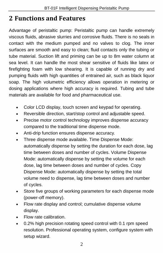
2 Functions and Features
Advantage of peristaltic pump: Peristaltic pump can handle extremely viscous fluids, abrasive slurries and corrosive fluids. There is no seals in contact with the medium pumped and no valves to clog. The inner surfaces are smooth and easy to clean; fluid contacts only the tubing or tube material. Suction lift and priming can be up to 8m water column at sea level. It can handle the most shear sensitive of fluids like latex or firefighting foam with low shearing. It is capable of running dry and pumping fluids with high quantities of entrained air, such as black liquor soap. The high volumetric efficiency allows operation in metering or dosing applications where high accuracy is required. Tubing and tube materials are available for food and pharmaceutical use.
• Color LCD display, touch screen and keypad for operating. • Reversible direction, start/stop control and adjustable speed. • Precise motor control technology improves dispense accuracy
compared to the traditional time dispense mode. • Anti-drip function ensures dispense accuracy. • Three dispense mode available. Time Dispense Mode:
automatically dispense by setting the duration for each dose, lag time between doses and number of cycles. Volume Dispense Mode: automatically dispense by setting the volume for each dose, lag time between doses and number of cycles. Copy Dispense Mode: automatically dispense by setting the total volume need to dispense, lag time between doses and number of cycles.
• Store five groups of working parameters for each dispense mode (power-off memory).
• Flow rate display and control; cumulative dispense volume display.
• Flow rate calibration. • 0.2% high precision rotating speed control with 0.1 rpm speed
resolution. Professional operating system, configure system with setup wizard.
2
BT-01F Intelligent Dispensing Peristaltic Pump • Intelligent temperature control to minimize working noise. • External logic level signal can control start/stop, direction and
easy dispense functions; external analog signal can adjust the rotating speed. Signal is optically isolated.
• With RS485 MODBUS interface, easy to communicated with external device.
• Internal double-deck isolation structure; circuit board with conformal coating makes it dust-proof and moisture proof.
• Anti-electromagnetic interference feature, wide input voltage range for complex power environment.
• ABS plastic housing, streamlined shape. • Drive multi-channels and various types of pump heads. • Optional footswitch and remote infrared control.
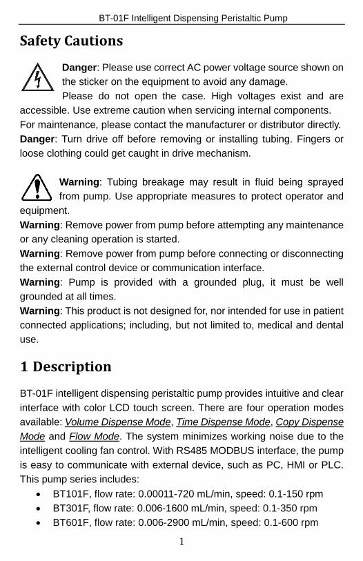
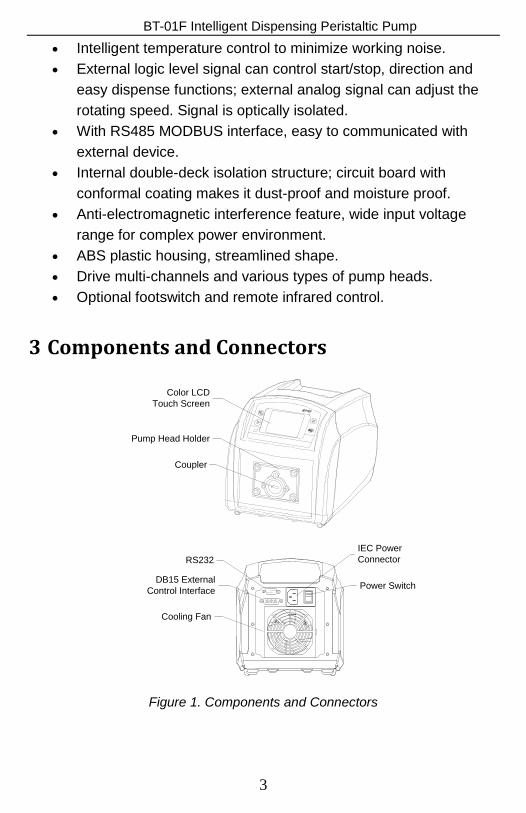
3 Components and Connectors
Color LCD Touch Screen
Pump Head Holder
Coupler
IEC Power Connector
Power SwitchDB15 External Control Interface
RS232
Cooling Fan
Figure 1. Components and Connectors
3
BT-01F Intelligent Dispensing Peristaltic Pump
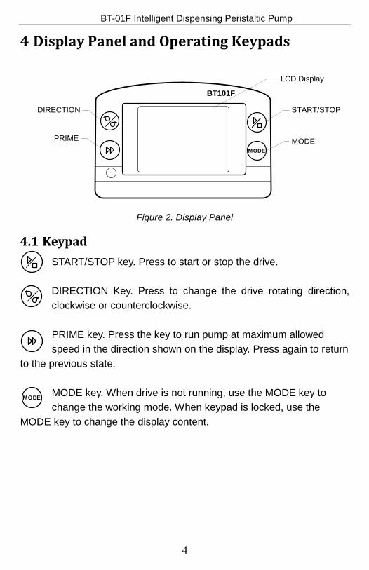
4 Display Panel and Operating Keypads
START/STOP
MODE
DIRECTION
PRIMEMODE
BT101F
LCD Display
Figure 2. Display Panel
4.1 Keypad START/STOP key. Press to start or stop the drive. DIRECTION Key. Press to change the drive rotating direction, clockwise or counterclockwise.
PRIME key. Press the key to run pump at maximum allowed speed in the direction shown on the display. Press again to return
to the previous state.
MODE key. When drive is not running, use the MODE key to change the working mode. When keypad is locked, use the
MODE key to change the display content.
MODE
4
BT-01F Intelligent Dispensing Peristaltic Pump
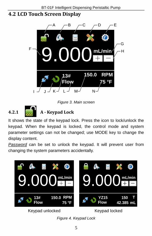
4.2 LCD Touch Screen Display
9.000mL/min+ -
13# 150.0 RPM
A B C D E
FG
H
I J K L M N
Flow 75 °F
Figure 3. Main screen
4.2.1 A - Keypad Lock
It shows the state of the keypad lock. Press the icon to lock/unlock the keypad. When the keypad is locked, the control mode and system parameter settings can not be changed; use MODE key to change the display content. Password can be set to unlock the keypad. It will prevent user from changing the system parameters accidentally.
9.000 mL/min+ -
13# 150.0 RPM75 °FFlow
9.000 mL/min+ -
YZ15 150 T42.385Flow mL
Keypad unlocked Keypad locked
Figure 4. Keypad Lock
5
BT-01F Intelligent Dispensing Peristaltic Pump
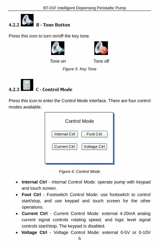
4.2.2 B - Tone Button
Press this icon to turn on/off the key tone.
Tone on Tone off
Figure 5. Key Tone
4.2.3 C - Control Mode
Press this icon to enter the Control Mode interface. There are four control modes available.
Control Mode
Internal Ctrl
Current Ctrl
Foot Ctrl
Voltage Ctrl
Figure 6. Control Mode
• Internal Ctrl - Internal Control Mode: operate pump with keypad and touch screen.
• Foot Ctrl - Footswitch Control Mode: use footswitch to control start/stop, and use keypad and touch screen for the other operations.
• Current Ctrl - Current Control Mode: external 4-20mA analog current signal controls rotating speed, and logic level signal controls start/stop. The keypad is disabled.
• Voltage Ctrl - Voltage Control Mode: external 0-5V or 0-10V 6
BT-01F Intelligent Dispensing Peristaltic Pump analog voltage signal controls rotating speed, and external logic level signal controls start/stop and direction. The keypad is disabled.
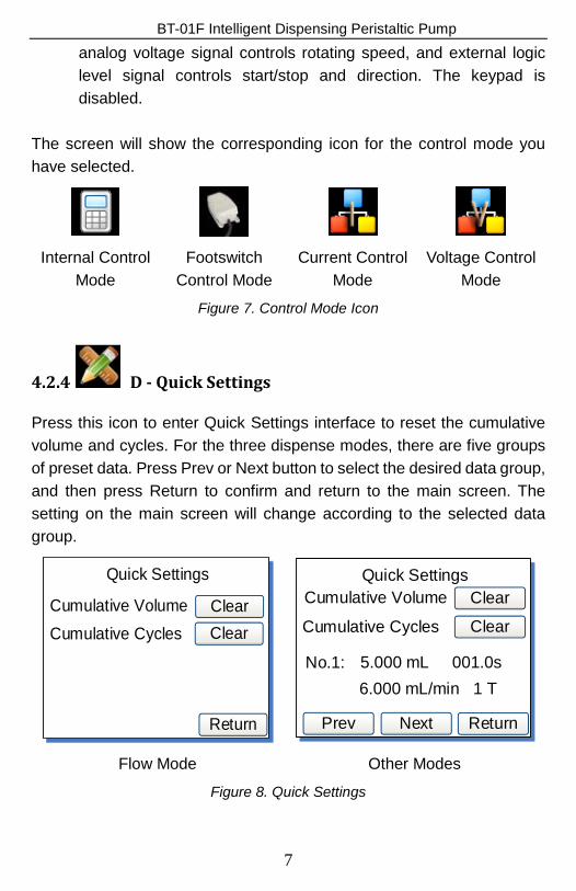
The screen will show the corresponding icon for the control mode you have selected.
Internal Control
Mode Footswitch
Control Mode Current Control
Mode Voltage Control
Mode
Figure 7. Control Mode Icon
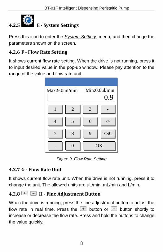
4.2.4 D - Quick Settings
Press this icon to enter Quick Settings interface to reset the cumulative volume and cycles. For the three dispense modes, there are five groups of preset data. Press Prev or Next button to select the desired data group, and then press Return to confirm and return to the main screen. The setting on the main screen will change according to the selected data group.
Quick Settings
Return
Cumulative Volume ClearCumulative Cycles Clear
Quick Settings
Return
Cumulative Volume Clear
Cumulative Cycles Clear
No.1: 5.000 mL 001.0s 6.000 mL/min 1 T
NextPrev
Flow Mode Other Modes
Figure 8. Quick Settings
7
BT-01F Intelligent Dispensing Peristaltic Pump
4.2.5 E - System Settings
Press this icon to enter the System Settings menu, and then change the parameters shown on the screen.
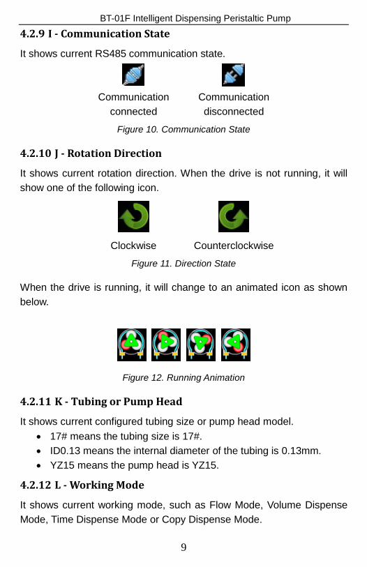
4.2.6 F - Flow Rate Setting
It shows current flow rate setting. When the drive is not running, press it to input desired value in the pop-up window. Please pay attention to the range of the value and flow rate unit.
1 -32
.
7
4
8
->65
9
0
ESC
OK
0.9Max:9.0ml/min Min:0.6ul/min
Figure 9. Flow Rate Setting
4.2.7 G - Flow Rate Unit
It shows current flow rate unit. When the drive is not running, press it to change the unit. The allowed units are µL/min, mL/min and L/min.
4.2.8 H - Fine Adjustment Button
When the drive is running, press the fine adjustment button to adjust the flow rate in real time. Press the button or button shortly to increase or decrease the flow rate. Press and hold the buttons to change the value quickly.
8
BT-01F Intelligent Dispensing Peristaltic Pump
4.2.9 I - Communication State
It shows current RS485 communication state.
Communication
connected Communication disconnected
Figure 10. Communication State
4.2.10 J - Rotation Direction
It shows current rotation direction. When the drive is not running, it will show one of the following icon.
Clockwise Counterclockwise
Figure 11. Direction State
When the drive is running, it will change to an animated icon as shown below.
Figure 12. Running Animation
4.2.11 K - Tubing or Pump Head
It shows current configured tubing size or pump head model. • 17# means the tubing size is 17#. • ID0.13 means the internal diameter of the tubing is 0.13mm. • YZ15 means the pump head is YZ15.
4.2.12 L - Working Mode
It shows current working mode, such as Flow Mode, Volume Dispense Mode, Time Dispense Mode or Copy Dispense Mode.
9
BT-01F Intelligent Dispensing Peristaltic Pump
4.2.13 M - Speed or Cumulative Cycles
It shows current speed or cumulative dispense cycles, switched by pressing MODE key. If the speed is higher than the maximum allowed speed, it will show U_Overflow; if the speed is lower than the minimum allowed speed, it will show D_Overflow. The cumulative cycles can be reset on Quick Settings menu.
4.2.14 N - Internal Temperature or Cumulative Volume
It shows the temperature inside the drive or cumulative volume that the pump has delivered. The cumulative volume can be reset on Quick Settings menu. The default display temperature is in Fahrenheit. To change display temperature in Celsius, please go to System Information window (see Figure 23), press the “75 °F” area, the display will change to Celsius, which is 24 °C. Press the “24 °C” area again, the display will switch back to Fahrenheit.
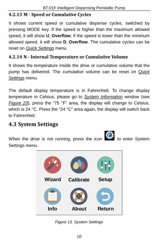
4.3 System Settings
When the drive is not running, press the icon to enter System Settings menu.
Wizard Calibrate Setup
Info About Return
Figure 13. System Settings
10
BT-01F Intelligent Dispensing Peristaltic Pump
4.3.1 Wizard
It’s a Wizard to set up the parameters. The system will select appropriate tubing and pump head for you.
4.3.2 Calibrate
Pump will accurately show current flow rate/volume after Flow Rate Calibration. Note: The calibration is necessary to display flow rate precisely.
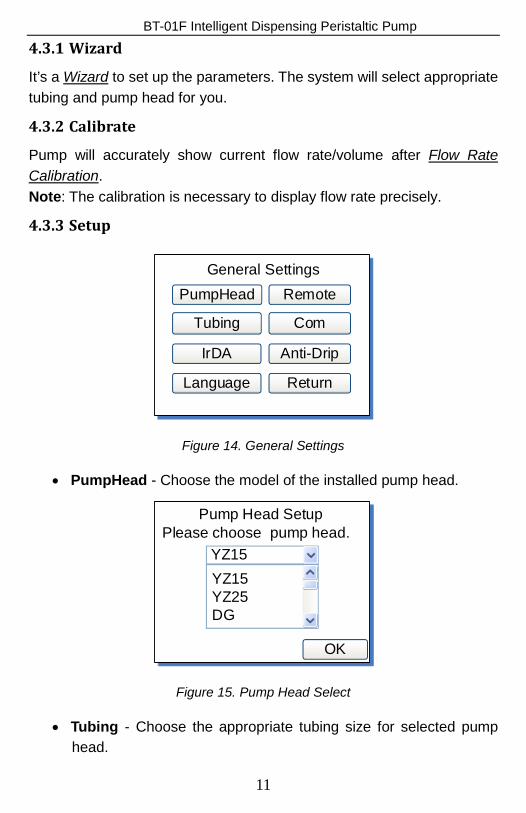
4.3.3 Setup
General SettingsPumpHead
Tubing
IrDA
Language
Remote
Com
Anti-Drip
Return
Figure 14. General Settings
• PumpHead - Choose the model of the installed pump head.
Pump Head Setup
YZ15
OK
YZ15 YZ25DG
Please choose pump head.
Figure 15. Pump Head Select
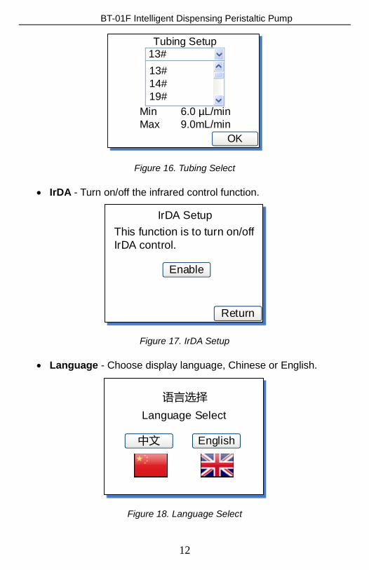
• Tubing - Choose the appropriate tubing size for selected pump head.
11
BT-01F Intelligent Dispensing Peristaltic Pump
Tubing Setup13#
OK
13# 14#19#
Min 6.0 µL/minMax 9.0mL/min
Figure 16. Tubing Select
• IrDA - Turn on/off the infrared control function.
IrDA Setup
Return
This function is to turn on/off IrDA control.
Enable
Figure 17. IrDA Setup
• Language - Choose display language, Chinese or English.
语言选择
English
Language Select
中文
Figure 18. Language Select
12
BT-01F Intelligent Dispensing Peristaltic Pump
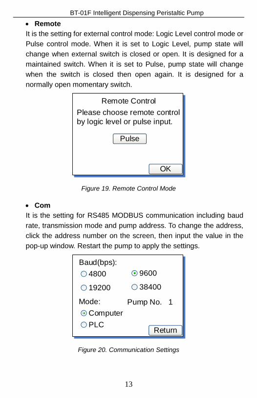
• Remote It is the setting for external control mode: Logic Level control mode or Pulse control mode. When it is set to Logic Level, pump state will change when external switch is closed or open. It is designed for a maintained switch. When it is set to Pulse, pump state will change when the switch is closed then open again. It is designed for a normally open momentary switch.
Remote Control
OK
Please choose remote control by logic level or pulse input.
Pulse
Figure 19. Remote Control Mode
• Com It is the setting for RS485 MODBUS communication including baud rate, transmission mode and pump address. To change the address, click the address number on the screen, then input the value in the pop-up window. Restart the pump to apply the settings.
Baud(bps):
Return
Mode:
4800
19200
9600
38400
Pump No. 1ComputerPLC
Figure 20. Communication Settings
13
BT-01F Intelligent Dispensing Peristaltic Pump
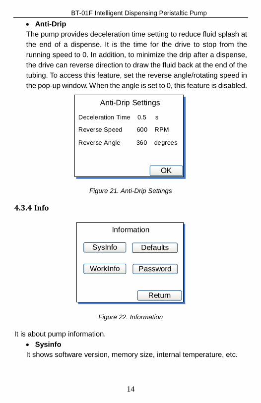
• Anti-Drip The pump provides deceleration time setting to reduce fluid splash at the end of a dispense. It is the time for the drive to stop from the running speed to 0. In addition, to minimize the drip after a dispense, the drive can reverse direction to draw the fluid back at the end of the tubing. To access this feature, set the reverse angle/rotating speed in the pop-up window. When the angle is set to 0, this feature is disabled.
Anti-Drip Settings
OK
Reverse Angle 360 degrees
Reverse Speed 600 RPM
Deceleration Time 0.5 s
Figure 21. Anti-Drip Settings
4.3.4 Info
Information
SysInfo
WorkInfo
Defaults
Password
Return
Figure 22. Information
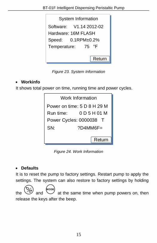
It is about pump information. • Sysinfo It shows software version, memory size, internal temperature, etc.
14
BT-01F Intelligent Dispensing Peristaltic Pump
System Information
Return
Software: V1.14 2012-02Hardware: 16M FLASHSpeed: 0.1RPM±0.2%Temperature: 75 °F
Figure 23. System Information
• Workinfo It shows total power on time, running time and power cycles.
Work Information
Return
Power on time: 5 D 8 H 29 MRun time: 0 D 5 H 01 MPower Cycles: 0000038 TSN: ?D4MM6F=
Figure 24. Work Information
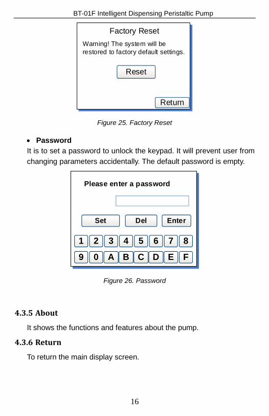
• Defaults It is to reset the pump to factory settings. Restart pump to apply the settings. The system can also restore to factory settings by holding
the and MODE
at the same time when pump powers on, then release the keys after the beep.
15
BT-01F Intelligent Dispensing Peristaltic Pump
Factory Reset
Return
Warning! The system will be restored to factory default settings.
Reset
Figure 25. Factory Reset
• Password It is to set a password to unlock the keypad. It will prevent user from changing parameters accidentally. The default password is empty.
Please enter a password
Set
1
Del Enter
8765432
9 FEDCBA0
Figure 26. Password
4.3.5 About
It shows the functions and features about the pump.
4.3.6 Return
To return the main display screen.
16
BT-01F Intelligent Dispensing Peristaltic Pump
5 External Control Interface
1 2 3 4 5 6 7 8
9 10 11 12 13 14 15
DB15
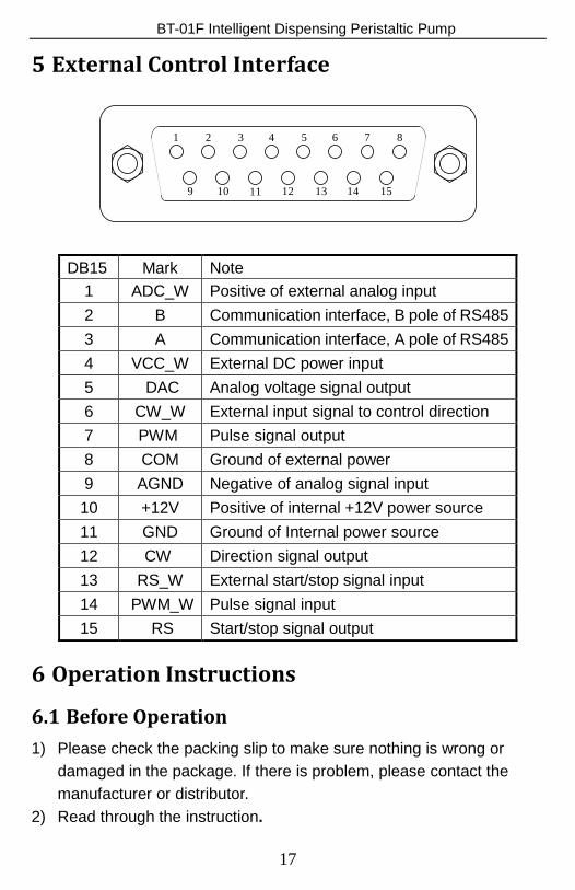
Mark Note 1 ADC_W Positive of external analog input 2 B Communication interface, B pole of RS485 3 A Communication interface, A pole of RS485 4 VCC_W External DC power input 5 DAC Analog voltage signal output 6 CW_W External input signal to control direction 7 PWM Pulse signal output 8 COM Ground of external power 9 AGND Negative of analog signal input 10 +12V Positive of internal +12V power source 11 GND Ground of Internal power source 12 CW Direction signal output 13 RS_W External start/stop signal input 14 PWM_W Pulse signal input 15 RS Start/stop signal output
6 Operation Instructions
6.1 Before Operation 1) Please check the packing slip to make sure nothing is wrong or
damaged in the package. If there is problem, please contact the manufacturer or distributor.
2) Read through the instruction.
17
BT-01F Intelligent Dispensing Peristaltic Pump 3) There should be more than 200 mm space for the back of the pump
when it is running.
6.2 Power Connection The voltage of the power supply should be marked on the sticker of the pump. Please make sure to use the right power source for the pump. Please plug the power cord into the power connector on the rear of the pump and plug the opposite end of the power cord into an electrical outlet. Flip the power switch located on the rear of the pump.
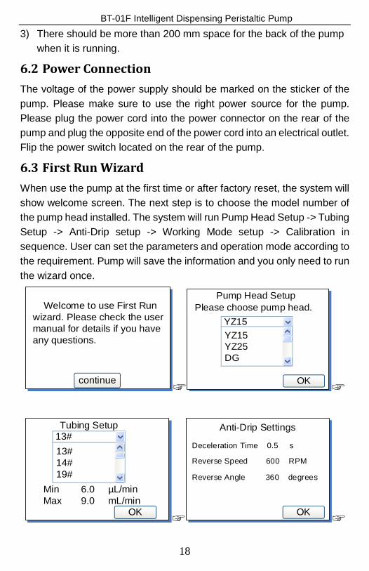
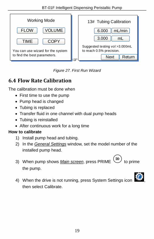
6.3 First Run Wizard When use the pump at the first time or after factory reset, the system will show welcome screen. The next step is to choose the model number of the pump head installed. The system will run Pump Head Setup -> Tubing Setup -> Anti-Drip setup -> Working Mode setup -> Calibration in sequence. User can set the parameters and operation mode according to the requirement. Pump will save the information and you only need to run the wizard once.
continue
Welcome to use First Run wizard. Please check the user manual for details if you have any questions.
☞
Pump Head Setup
YZ15
OK
YZ15 YZ25DG
Please choose pump head.
☞
Tubing Setup13#
OK
13# 14#19#
Min 6.0 µL/minMax 9.0 mL/min
☞
Anti-Drip Settings
OK
Reverse Angle 360 degrees
Reverse Speed 600 RPM
Deceleration Time 0.5 s
☞
18
BT-01F Intelligent Dispensing Peristaltic Pump
Working Mode
FLOW
TIME
VOLUME
COPY
You can use wizard for the system to find the best parameters.
☞
13# Tubing Calibration
Return
6.000 mL/min
3.000 mL
Next
Suggested testing vol >3.000mLto reach 0.5% precision.
--
Figure 27. First Run Wizard
6.4 Flow Rate Calibration The calibration must be done when
• First time to use the pump • Pump head is changed • Tubing is replaced • Transfer fluid in one channel with dual pump heads • Tubing is reinstalled • After continuous work for a long time
How to calibrate 1) Install pump head and tubing. 2) In the General Settings window, set the model number of the
installed pump head.
3) When pump shows Main screen, press PRIME to prime the pump.
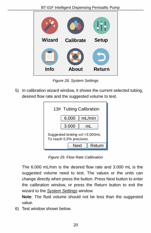
4) When the drive is not running, press System Settings icon , then select Calibrate.
19
BT-01F Intelligent Dispensing Peristaltic Pump
Wizard Calibrate Setup
Info About Return
Figure 28. System Settings
5) In calibration wizard window, it shows the current selected tubing, desired flow rate and the suggested volume to test.
13# Tubing Calibration
Return
6.000 mL/min
3.000 mL
Next
Suggested testing vol >3.000mLTo reach 0.5% precision.
Figure 29. Flow Rate Calibration
The 6.000 mL/min is the desired flow rate and 3.000 mL is the suggested volume need to test. The values or the units can change directly when press the button. Press Next button to enter the calibration window, or press the Return button to exit the wizard to the System Settings window. Note: The fluid volume should not be less than the suggested value.
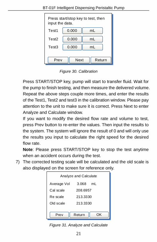
6) Test window shown below.
20
BT-01F Intelligent Dispensing Peristaltic Pump
Press start/stop key to test, then input the data.
Return
0.000 mL
0.000 mL
Next
Test1
Test2
Test3 0.000 mL
Prev
Figure 30. Calibration
Press START/STOP key, pump will start to transfer fluid. Wait for the pump to finish testing, and then measure the delivered volume. Repeat the above steps couple more times, and enter the results of the Test1, Test2 and test3 in the calibration window. Please pay attention to the unit to make sure it is correct. Press Next to enter Analyze and Calculate window. If you want to modify the desired flow rate and volume to test, press Prev button to re-enter the values. Then input the results to the system. The system will ignore the result of 0 and will only use the results you input to calculate the right speed for the desired flow rate. Note: Please press START/STOP key to stop the test anytime when an accident occurs during the test.
7) The corrected testing scale will be calculated and the old scale is also displayed on the screen for reference only.
Analyze and Calculate
Return
Average Vol 3.068 mL
Cal scale 208.6957
Re scale 213.3330
Old scale 213.3330
OKPrev
Figure 31. Analyze and Calculate
21
BT-01F Intelligent Dispensing Peristaltic Pump The scale is a coefficient for the tubing. The calculated scale should be close to the reference scale (the “Re scale” shown on Figure 31). Otherwise, please check the following and press Prev to test again.
• The accuracy of the volume measurement • The volume unit setting • The model of the pump head setting • The tubing size setting • The liquid viscosity. When it is too high, the flow rate may not be
linear to the speed. • If dual pump heads are used for one channel
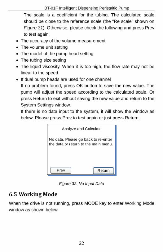
If no problem found, press OK button to save the new value. The pump will adjust the speed according to the calculated scale. Or press Return to exit without saving the new value and return to the System Settings window. If there is no data input to the system, it will show the window as below. Please press Prev to test again or just press Return.
Analyze and Calculate
Return
No data. Please go back to re-enter the data or return to the main menu.
Prev
Figure 32. No Input Data
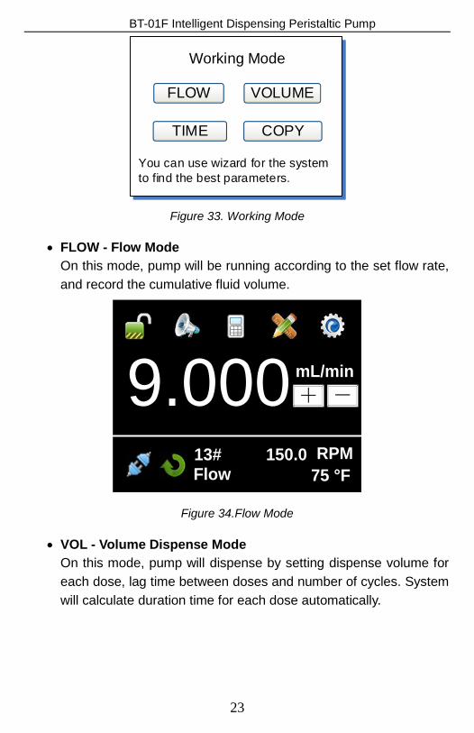
6.5 Working Mode When the drive is not running, press MODE key to enter Working Mode window as shown below.
22
BT-01F Intelligent Dispensing Peristaltic Pump
Working Mode
FLOW
TIME
VOLUME
COPY
You can use wizard for the system to find the best parameters.
Figure 33. Working Mode
• FLOW - Flow Mode On this mode, pump will be running according to the set flow rate, and record the cumulative fluid volume.
9.000 mL/min+ -
13# 150.0 RPM75 °FFlow
Figure 34.Flow Mode
• VOL - Volume Dispense Mode On this mode, pump will dispense by setting dispense volume for each dose, lag time between doses and number of cycles. System will calculate duration time for each dose automatically.
23
BT-01F Intelligent Dispensing Peristaltic Pump
5.000mL
13# 150.0 RPM0033.33Vol 01
9.000mL/min
001.0 S
2 T
A
B
C
D
SE
F
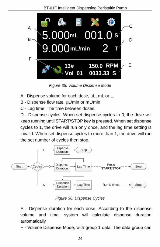
Figure 35. Volume Dispense Mode
A - Dispense volume for each dose, µL, mL or L. B - Dispense flow rate, µL/min or mL/min. C - Lag time. The time between doses. D - Dispense cycles. When set dispense cycles to 0, the drive will keep running until START/STOP key is pressed. When set dispense cycles to 1, the drive will run only once, and the lag time setting is invalid. When set dispense cycles to more than 1, the drive will run the set number of cycles then stop.
Cycles
Stop
Start Dispense Duration
Dispense Duration1
0
Dispense DurationN Lag Time
Lag Time StopPress START/STOP
StopRun N times
Figure 36. Dispense Cycles
E - Dispense duration for each dose. According to the dispense volume and time, system will calculate dispense duration automatically. F - Volume Dispense Mode, with group 1 data. The data group can
24
BT-01F Intelligent Dispensing Peristaltic Pump be selected from the Quick Settings menu.
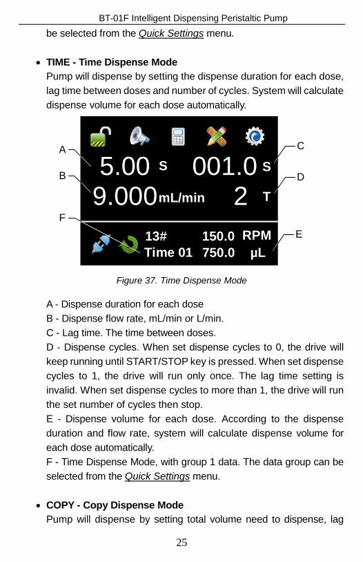
• TIME - Time Dispense Mode
Pump will dispense by setting the dispense duration for each dose, lag time between doses and number of cycles. System will calculate dispense volume for each dose automatically.
5.00 S
13# 150.0 RPMTime 01
9.000mL/min
001.0 S
2 T
A
B
C
D
750.0 µLE
F
Figure 37. Time Dispense Mode
A - Dispense duration for each dose B - Dispense flow rate, mL/min or L/min. C - Lag time. The time between doses. D - Dispense cycles. When set dispense cycles to 0, the drive will keep running until START/STOP key is pressed. When set dispense cycles to 1, the drive will run only once. The lag time setting is invalid. When set dispense cycles to more than 1, the drive will run the set number of cycles then stop. E - Dispense volume for each dose. According to the dispense duration and flow rate, system will calculate dispense volume for each dose automatically. F - Time Dispense Mode, with group 1 data. The data group can be selected from the Quick Settings menu.
• COPY - Copy Dispense Mode Pump will dispense by setting total volume need to dispense, lag
25
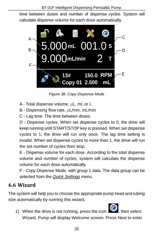
BT-01F Intelligent Dispensing Peristaltic Pump time between doses and number of dispense cycles. System will calculate dispense volume for each dose automatically.
5.000mL
13# 150.0 RPMCopy 01
9.000mL/min
001.0 S
2 T
A
B
C
D
2.500 mLE
F
Figure 38. Copy Dispense Mode
A - Total dispense volume, µL, mL or L B - Dispensing flow rate, µL/min, mL/min C - Lag time. The time between doses. D - Dispense cycles. When set dispense cycles to 0, the drive will keep running until START/STOP key is pressed. When set dispense cycles to 1, the drive will run only once. The lag time setting is invalid. When set dispense cycles to more than 1, the drive will run the set number of cycles then stop. E - Dispense volume for each dose. According to the total dispense volume and number of cycles, system will calculate the dispense volume for each dose automatically. F - Copy Dispense Mode, with group 1 data. The data group can be selected from the Quick Settings menu.
6.6 Wizard The system will help you to choose the appropriate pump head and tubing size automatically by running this wizard.
1) When the drive is not running, press the icon , then select Wizard. Pump will display Welcome screen. Press Next to enter
26
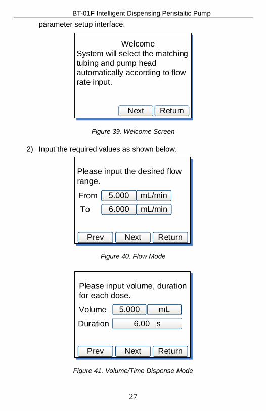
BT-01F Intelligent Dispensing Peristaltic Pump parameter setup interface.
Return
WelcomeSystem will select the matching tubing and pump head automatically according to flow rate input.
Next
Figure 39. Welcome Screen
2) Input the required values as shown below.
Next
Please input the desired flow range.
Return
FromTo
Prev
5.000
6.000
mL/min
mL/min
Figure 40. Flow Mode
Next
Please input volume, duration for each dose.
Return
VolumeDuration
Prev
5.000
6.00 s
mL
Figure 41. Volume/Time Dispense Mode
27
BT-01F Intelligent Dispensing Peristaltic Pump
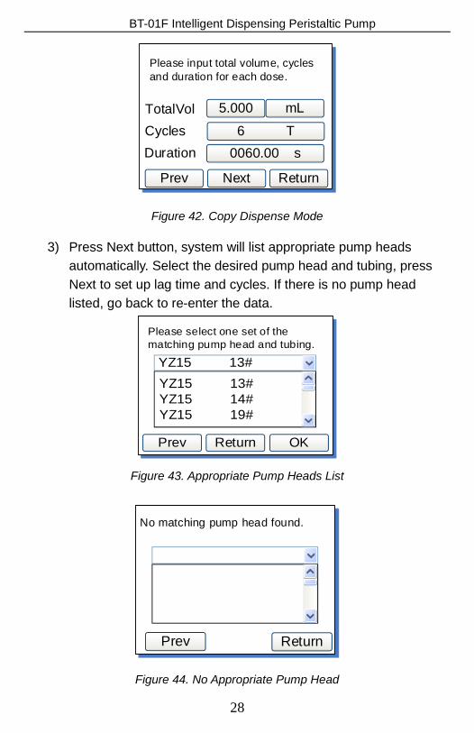
Next
Please input total volume, cycles and duration for each dose.
Return
TotalVolCycles
Prev
5.0006 T
mL
Duration 0060.00 s
Figure 42. Copy Dispense Mode
3) Press Next button, system will list appropriate pump heads automatically. Select the desired pump head and tubing, press Next to set up lag time and cycles. If there is no pump head listed, go back to re-enter the data.
Return
Please select one set of the matching pump head and tubing.
Prev
YZ15 13#YZ15 13#YZ15 14#YZ15 19#
OK
Figure 43. Appropriate Pump Heads List
Return
No matching pump head found.
Prev
Figure 44. No Appropriate Pump Head
28
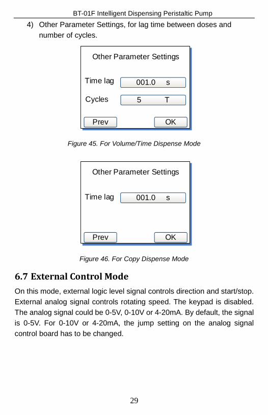
BT-01F Intelligent Dispensing Peristaltic Pump 4) Other Parameter Settings, for lag time between doses and
number of cycles.
Other Parameter Settings
OK
Time lag
Cycles
Prev
001.0 s
5 T
Figure 45. For Volume/Time Dispense Mode
Other Parameter Settings
OK
Time lag
Prev
001.0 s
Figure 46. For Copy Dispense Mode
6.7 External Control Mode On this mode, external logic level signal controls direction and start/stop. External analog signal controls rotating speed. The keypad is disabled. The analog signal could be 0-5V, 0-10V or 4-20mA. By default, the signal is 0-5V. For 0-10V or 4-20mA, the jump setting on the analog signal control board has to be changed.
29
BT-01F Intelligent Dispensing Peristaltic Pump
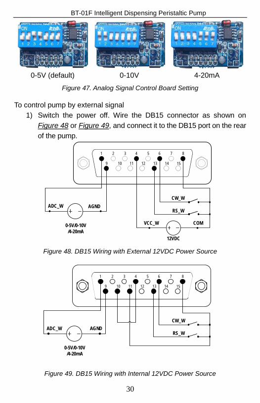
0-5V (default) 0-10V 4-20mA
Figure 47. Analog Signal Control Board Setting
To control pump by external signal 1) Switch the power off. Wire the DB15 connector as shown on
Figure 48 or Figure 49, and connect it to the DB15 port on the rear of the pump.
1 2 3 4 5 6 7 8
9 10 11 12 13 14 15
ADC_W AGND
0-5V/0-10V/4-20mA
12VDC
VCC_W COM
RS_W
CW_W
Figure 48. DB15 Wiring with External 12VDC Power Source
1 2 3 4 5 6 7 8
9 10 11 12 13 14 15
ADC_W AGND
0-5V/0-10V/4-20mA
RS_W
CW_W
Figure 49. DB15 Wiring with Internal 12VDC Power Source
30
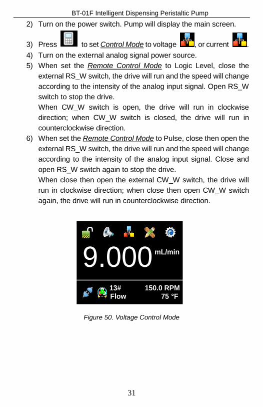
BT-01F Intelligent Dispensing Peristaltic Pump 2) Turn on the power switch. Pump will display the main screen.
3) Press to set Control Mode to voltage , or current . 4) Turn on the external analog signal power source. 5) When set the Remote Control Mode to Logic Level, close the
external RS_W switch, the drive will run and the speed will change according to the intensity of the analog input signal. Open RS_W switch to stop the drive. When CW_W switch is open, the drive will run in clockwise direction; when CW_W switch is closed, the drive will run in counterclockwise direction.
6) When set the Remote Control Mode to Pulse, close then open the external RS_W switch, the drive will run and the speed will change according to the intensity of the analog input signal. Close and open RS_W switch again to stop the drive. When close then open the external CW_W switch, the drive will run in clockwise direction; when close then open CW_W switch again, the drive will run in counterclockwise direction.
9.000 mL/min
13#Flow
150.0 RPM°F75
Figure 50. Voltage Control Mode
31
BT-01F Intelligent Dispensing Peristaltic Pump
9.000mL/min
13#Flow
150.0 RPM°F75
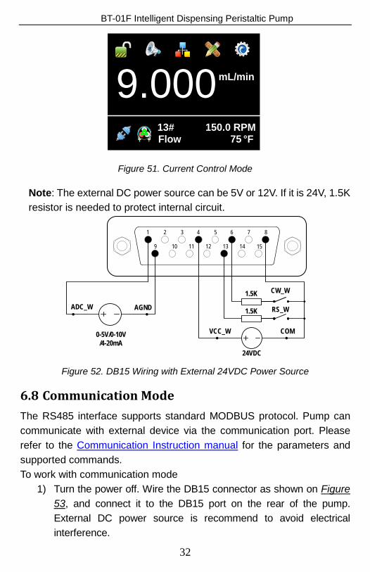
Figure 51. Current Control Mode
Note: The external DC power source can be 5V or 12V. If it is 24V, 1.5K resistor is needed to protect internal circuit.
1 2 3 4 5 6 7 8
9 10 11 12 13 14 15
ADC_W AGND
0-5V/0-10V/4-20mA
24VDC
VCC_W COM
RS_W
CW_W1.5K
1.5K
Figure 52. DB15 Wiring with External 24VDC Power Source
6.8 Communication Mode The RS485 interface supports standard MODBUS protocol. Pump can communicate with external device via the communication port. Please refer to the Communication Instruction manual for the parameters and supported commands. To work with communication mode
1) Turn the power off. Wire the DB15 connector as shown on Figure 53, and connect it to the DB15 port on the rear of the pump. External DC power source is recommend to avoid electrical interference.
32
BT-01F Intelligent Dispensing Peristaltic Pump
1 2 3 4 5 6 7 8
9 10 11 12 13 14 15
12VDC
VCC_W COM
B
A
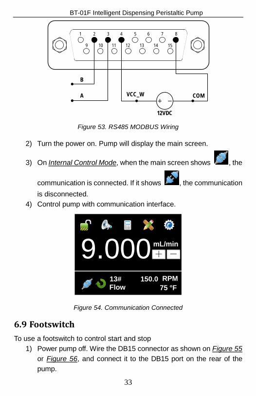
Figure 53. RS485 MODBUS Wiring
2) Turn the power on. Pump will display the main screen.
3) On Internal Control Mode, when the main screen shows , the
communication is connected. If it shows , the communication is disconnected.
4) Control pump with communication interface.
9.000 mL/min+ -
13# 150.0 RPM75 °FFlow
Figure 54. Communication Connected
6.9 Footswitch To use a footswitch to control start and stop
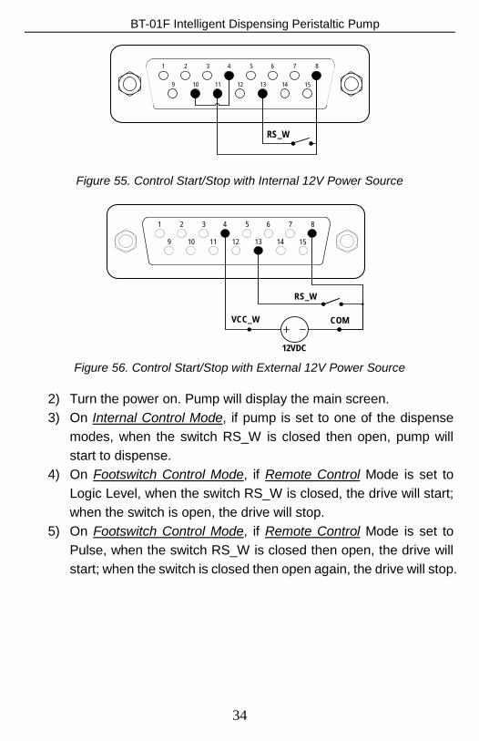
1) Power pump off. Wire the DB15 connector as shown on Figure 55 or Figure 56, and connect it to the DB15 port on the rear of the pump.
33
BT-01F Intelligent Dispensing Peristaltic Pump
1 2 3 4 5 6 7 8
9 10 11 12 13 14 15
RS_W
Figure 55. Control Start/Stop with Internal 12V Power Source
1 2 3 4 5 6 7 8
9 10 11 12 13 14 15
12VDC
VCC_W COM
RS_W
Figure 56. Control Start/Stop with External 12V Power Source
2) Turn the power on. Pump will display the main screen. 3) On Internal Control Mode, if pump is set to one of the dispense
modes, when the switch RS_W is closed then open, pump will start to dispense.
4) On Footswitch Control Mode, if Remote Control Mode is set to Logic Level, when the switch RS_W is closed, the drive will start; when the switch is open, the drive will stop.
5) On Footswitch Control Mode, if Remote Control Mode is set to Pulse, when the switch RS_W is closed then open, the drive will start; when the switch is closed then open again, the drive will stop.
34
BT-01F Intelligent Dispensing Peristaltic Pump
9.000mL/min+ -
13#Flow
150.0 RPM°F75
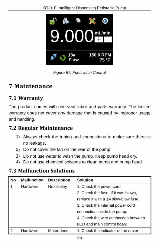
Figure 57. Footswitch Control
7 Maintenance
7.1 Warranty The product comes with one-year labor and parts warranty. The limited warranty does not cover any damage that is caused by improper usage and handling.
7.2 Regular Maintenance 1) Always check the tubing and connections to make sure there is
no leakage. 2) Do not cover the fan on the rear of the pump. 3) Do not use water to wash the pump. Keep pump head dry. 4) Do not use chemical solvents to clean pump and pump head.
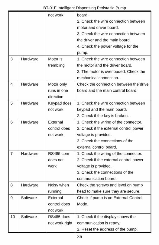
7.3 Malfunction Solutions No Malfunction Description Solution 1 Hardware No display 1. Check the power cord
2. Check the fuse. If it was blown, replace it with a 1A slow-blow fuse 3. Check the internal power cord connection inside the pump. 4. Check the wire connection between LCD and main control board.
2 Hardware Motor does 1. Check the indicator of the driver
35
BT-01F Intelligent Dispensing Peristaltic Pump
not work board. 2. Check the wire connection between motor and driver board. 3. Check the wire connection between the driver and the main board. 4. Check the power voltage for the pump.
3 Hardware Motor is trembling
1. Check the wire connection between the motor and the driver board. 2. The motor is overloaded. Check the mechanical connection.
4 Hardware Motor only runs in one direction
Check the connection between the drive board and the main control board.
5 Hardware Keypad does not work
1. Check the wire connection between keypad and the main board. 2. Check if the key is broken.
6 Hardware External control does not work
1. Check the wiring of the connector. 2. Check if the external control power voltage is provided. 3. Check the connections of the external control board.
7 Hardware RS485 com does not work
1. Check the wiring of the connector. 2. Check if the external control power voltage is provided. 3. Check the connections of the communication board.
8 Hardware Noisy when running
Check the screws and level on pump head to make sure they are secure.
9 Software External control does not work
Check if pump is on External Control Mode.
10 Software RS485 does not work right
1. Check if the display shows the communication is ready. 2. Reset the address of the pump.
36
BT-01F Intelligent Dispensing Peristaltic Pump
3. Check whether on the bus there are two pumps using the same address
If the problem can not be solved, please contact the manufacturer
or distributor.
8 Dimensions
182257
198
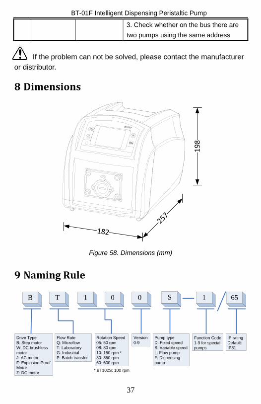
Figure 58. Dimensions (mm)
9 Naming Rule
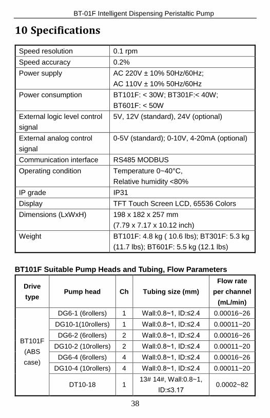
TB 1 0 0 S
Drive TypeB: Step motorW: DC brushless motorJ: AC motorF: Explosion Proof MotorZ: DC motor
1 65
Function Code1-9 for special pumps
Version0-9
Rotation Speed05: 50 rpm08: 80 rpm10: 150 rpm *30: 350 rpm60: 600 rpm
Flow RateQ: MicroflowT: LaboratoryG: IndustrialP: Batch transfer
IP ratingDefault: IP31
Pump typeD: Fixed speedS: Variable speedL: Flow pumpF: Dispensing pump
* BT102S: 100 rpm
37
BT-01F Intelligent Dispensing Peristaltic Pump
10 Specifications
Speed resolution 0.1 rpm Speed accuracy 0.2% Power supply AC 220V ± 10% 50Hz/60Hz;
AC 110V ± 10% 50Hz/60Hz Power consumption BT101F: < 30W; BT301F:< 40W;
BT601F: < 50W External logic level control signal
5V, 12V (standard), 24V (optional)
External analog control signal
0-5V (standard); 0-10V, 4-20mA (optional)
Communication interface RS485 MODBUS Operating condition Temperature 0~40°C,
Relative humidity <80% IP grade IP31 Display TFT Touch Screen LCD, 65536 Colors Dimensions (LxWxH) 198 x 182 x 257 mm
(7.79 x 7.17 x 10.12 inch) Weight BT101F: 4.8 kg ( 10.6 lbs); BT301F: 5.3 kg
(11.7 lbs); BT601F: 5.5 kg (12.1 lbs) BT101F Suitable Pump Heads and Tubing, Flow Parameters
Drive type
Pump head Ch Tubing size (mm) Flow rate
per channel (mL/min)
BT101F (ABS case)
DG6-1 (6rollers) 1 Wall:0.8~1, ID:≤2.4 0.00016~26 DG10-1(10rollers) 1 Wall:0.8~1, ID:≤2.4 0.00011~20 DG6-2 (6rollers) 2 Wall:0.8~1, ID:≤2.4 0.00016~26
DG10-2 (10rollers) 2 Wall:0.8~1, ID:≤2.4 0.00011~20 DG6-4 (6rollers) 4 Wall:0.8~1, ID:≤2.4 0.00016~26
DG10-4 (10rollers) 4 Wall:0.8~1, ID:≤2.4 0.00011~20
DT10-18 1 13# 14#, Wall:0.8~1,
ID:≤3.17 0.0002~82
38
BT-01F Intelligent Dispensing Peristaltic Pump
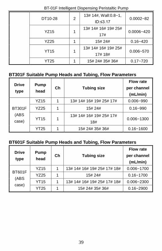
DT10-28 2 13# 14#, Wall:0.8~1,
ID:≤3.17 0.0002~82
YZ15 1 13# 14# 16# 19# 25#
17# 0.0006~420
YZ25 1 15# 24# 0.16~420
YT15 1 13# 14# 16# 19# 25#
17# 18# 0.006~570
YT25 1 15# 24# 35# 36# 0.17~720
BT301F Suitable Pump Heads and Tubing, Flow Parameters
Drive type
Pump head
Ch Tubing size Flow rate
per channel (mL/min)
BT301F (ABS case)
YZ15 1 13# 14# 16# 19# 25# 17# 0.006~990
YZ25 1 15# 24# 0.16~990
YT15 1 13# 14# 16# 19# 25# 17#
18# 0.006~1300
YT25 1 15# 24# 35# 36# 0.16~1600
BT601F Suitable Pump Heads and Tubing, Flow Parameters
Drive type
Pump head
Ch Tubing size Flow rate
per channel (mL/min)
BT601F (ABS case)
YZ15 1 13# 14# 16# 19# 25# 17# 18# 0.006~1700 YZ25 1 15# 24# 0.16~1700 YT15 1 13# 14# 16# 19# 25# 17# 18# 0.006~2300 YT25 1 15# 24# 35# 36# 0.16~2900
39