for k-series, lh-series, and dlh-series open - steel … spec 5nov15 final.pdf · american national...
TRANSCRIPT
American National Standard SJI 100 - 2015
Page 1 of 38
K-Series Adopted by the Steel Joist Institute November 4, 1985 LH/DLH-Series Adopted by the Steel Joist Institute May 10, 2006
Joist Girders Adopted by the Steel Joist Institute November 4, 1985 Revised to November 10, 2014, Effective January 1, 2015
1.1 SCOPE The Standard Specification for K-Series, LH-Series, DLH-Series Open Web Steel Joists and for Joist Girders, hereafter referred to as the Specification, covers the design, manufacture, application, and erection stability and handling of Joist Girders and Open Web Steel Joists K-Series, LH-Series, and DLH-Series in buildings or other structures, where other structures are defined as those structures designed, manufactured, and erected in a manner similar to buildings. Joist Girders and K-Series, LH-Series, and DLH-Series joists shall be designed using Allowable Stress Design (ASD) or Load and Resistance Factor Design (LRFD) in accordance with this Specification. Included as part of this specification are KCS joists, K-Series; Joist Substitutes, K-Series; and Top Chord Extensions and Extended Ends, K-Series. 1.2 OTHER REGULATIONS Joist Girders and K-Series, LH-Series, and DLH-Series joists shall be erected in accordance with the Occupational Safety and Health Administration (OSHA), 29 CFR Part 1926, Safety Standards for Steel Erection, Subpart R – Steel Erection. The erection of Joist Girders and K-Series, LH-Series, and DLH-Series joists 144 ft. (43.9 m) or less in length shall be in accordance with the requirements of Section 1926.757, Open Web Steel Joists. Joist Girders and DLH–Series joists greater than 144 ft. (43.9 m) in length shall be in accordance with the requirements of Section 1926.756 Beams and Columns. 1.3 APPLICATION This Specification includes Section 1 through Section 6. The user notes shall not be part of the Specification. User Note: User notes are intended to provide practical guidance in the use and application of this Specification. 1.4 DEFINITIONS The following terms shall, for the purposes of this Specification, have the meanings shown in this Section. Where terms are not defined in this Section, those terms shall have their ordinary accepted meanings in the context in which it applies. Joist Girders, K-Series, LH-Series, and DLH-Series shall be open web, in-plane load-carrying steel members utilizing hot-rolled or cold-formed steel, including cold-formed steel whose yield strength has been attained by cold working. Joist Girders shall be open web steel trusses used as primary framing members designed as simple spans supporting in-plane concentrated loads for a floor or roof system. These concentrated loads shall be considered to act at the top chord
STANDARD SPECIFICATION
FOR K-SERIES, LH-SERIES, AND DLH-SERIES OPEN
WEB STEEL JOISTS AND FOR JOIST GIRDERS.
SECTION 1.
SCOPE AND DEFINITIONS
American National Standard SJI 100 - 2015
Page 2 of 38
panel points of the Joist Girders unless otherwise specified. The Joist Girder standard designation in ASD shall be established by its nominal depth in inches (mm), the letter “G”, followed by the number of joist spaces, the letter “N”, and finally the load in kips (kN) at each panel point, and the letter “K”. The Joist Girder standard designation in LRFD shall be established by its nominal depth in inches (mm), the letter “G”, followed by the number of joist spaces, the letter “N”, and finally the factored load in kips (kN) at each panel point, and the letter “F”. Joist Girders shall be designed in accordance with this specification to support the loads defined by the specifying professional.
Joist Girders shall be designed and manufactured as either simple framing members with underslung ends and bottom chord extensions or as part of an ordinary steel moment frame (OMF). Where used as part of an OMF the specifying professional shall be responsible for carrying out all the required frame analyses (i.e. first-order and second-order), provide all the required load information and stiffness data to the joist manufacturer, and indicate the type of Joist Girder to column connections that are being designed on the structural drawings. User Note: Joist Girders have been standardized in depths from 20 inches (508 mm) through 120 inches (3048 mm), for spans from 20 feet (6096 mm) through 120 feet (36576 mm). Where this Specification refers to “steel joists”, this shall mean the K-Series, LH-Series, and DLH-Series joists. User Note: Joists are suitable for the direct support of floors and roof slabs or decks. The K-Series joists are standardized in depths from 10 inches (254 mm) through 30 inches (762 mm), for spans up through 60 feet (18288 mm). The LH-Series joists are standardized in depths from 18 inches (457 mm) through 48 inches (1219 mm), for spans up through 96 feet (29261 mm). The DLH-Series joists are standardized in depths from 52 inches (1321 mm) through 120 inches (3048 mm), for spans up through 240 feet (73152 mm). The K-Series, LH-Series and DLH-Series standard joist designations shall be established by their nominal depth, followed by the letters K, LH or DLH as appropriate, and then by the Section Number designation assigned. The Section Number designations shall range from 01 to 25. The K-Series, LH-Series and DLH-Series standard joist designations listed in the following Standard Load Tables shall support the uniformly distributed loads as provided in the applicable tables:
Standard LRFD Load Table Open Web Steel Joists, K-Series – U.S. Customary Units Standard ASD Load Table Open Web Steel Joists, K-Series – U.S. Customary Units Standard LRFD Load Table Longspan Steel Joists, LH-Series – U.S. Customary Units Standard ASD Load Table Longspan Steel Joists, LH-Series – U.S. Customary Units Standard LRFD Load Table Deep Longspan Steel Joists, DLH-Series – U.S. Customary Units Standard ASD Load Table Deep Longspan Steel Joists, DLH-Series – U.S. Customary Units Standard LRFD Load Table Open Web Steel Joists, K-Series – S.I. Units Standard ASD Load Table Open Web Steel Joists, K-Series – S.I. Units Standard LRFD Load Table Longspan Steel Joists, LH-Series – S.I. Units Standard ASD Load Table Longspan Steel Joists, LH-Series – S.I. Units Standard LRFD Load Table Deep Longspan Steel Joists, DLH-Series – S.I. Units Standard ASD Load Table Deep Longspan Steel Joists, DLH-Series – S.I. Units
Wherever a standard SJI Section Number is specified in the joist designation (i.e. 18K4, 32LH10) and other design load cases are also specified for the joist, the steel joist shall be designed for the corresponding total load as shown in the Standard Load Tables as a minimum. User Note: Six standard types of K-Series, LH-Series and DLH-Series joists are designed and manufactured. These types are underslung (top chord bearing) or square-ended (bottom chord bearing), with parallel chords or with single or double pitched top chords. The Standard Load Tables apply for a pitched top chord up to 1/2 inch per foot (1:24). The steel joist or Joist Girder designation depth shall be the depth at mid-span. An alternate method of specifying a standard K-Series, LH-Series, or DLH-Series joist shall be permitted by providing the designation in a “load/load” sequence. The format used shall be ddKtl/ll, ddLHtl/ll, or ddDLHtl/ll where:
American National Standard SJI 100 - 2015
Page 3 of 38
dd is the nominal depth of the joist in inches (mm) tl is the total uniformly distributed load applied to the joist top chord, plf (kN/m) ll is the uniform live load for which the deflection shall be checked and limited as required by this Specification, plf (kN/m)
User Note: The load/load K-Series, LH-Series, or DLH-Series joists can be specified in depths from 10 inches (254 mm) through 120 inches (3048 mm) and spans up through 240 feet (73152 mm). The maximum uniformly distributed load-carrying capacity of 2400 plf (35.03 kN/m) in ASD and 3600 plf (52.54 kN/m) in LRFD has been established for this alternate K-Series, LH-Series, or DLH-Series format. The maximum capacity for any given load/load joist designation is a function of span, depth and chord member size. When requirements exceed the standard K-Series load table limitations for loading, span, and depth, an LH-Series designation is recommended to facilitate the proper determination of minimum seat depth, end anchorage, bridging size, deck attachment, etc. Thus, any joist exceeding a 30 inch depth, a span of 60 feet, an in-kip moment of Depth x 61 kips in ASD or Depth x 91.5 kips in LRFD, or an end reaction of 9.2 kips in ASD or 13.8 kips in LRFD should be designated as an LH-Series which allows for a cross-reference with a standard LH designation as listed in this Specification for seat, end anchorage, bridging, attachment tables, etc. A KCS Joist is a particular type of K-Series joist, and shall be designed in accordance with this Specification based on an envelope of moment and shear capacity, rather than uniform load capacity, to support uniform plus concentrated loads or other non-uniform loads. The KCS Joists shall be selected from standardized depths from 10 inches (254 mm) through 30 inches (762 mm), for spans up through 60 feet (18288 mm). The maximum total safe uniformly distributed load-carrying capacity of a KCS Joist, K-Series, shall be 550 plf (8.02 kN/m) in ASD or 825 plf (12.03 kN/m) in LRFD. A KCS Joist shall be parallel chord only and shall be permitted to be underslung or bottom chord bearing. The KCS Joists, K-Series, standard designations shall be established by their nominal depth, followed by the letters “KCS”, and then by the Section Number designation assigned. The Section Number designations shall range from 1 to 5. A KCS Joist shall not be designated using the alternate “load/load” method. The KCS Joists, K-Series, standard designations listed in the following Standard Load Tables shall provide the moment capacity and shear capacity as listed in the applicable tables:
Standard LRFD Load Table for KCS Open Web Steel Joists – U.S. Customary Units Standard ASD Load Table for KCS Open Web Steel Joists – U.S. Customary Units Standard LRFD Load Table for KCS Open Web Steel Joists – S.I. Units Standard ASD Load Table for KCS Open Web Steel Joists – S.I. Units
Where an open web configuration becomes impractical, a Joist Substitute, K-Series, shall be designed in accordance with this Specification to support uniform loads when the span is less than 10 feet (3048 mm). The maximum total safe uniformly distributed load-carrying capacity of a Joist Substitute shall be 550 plf (8.02 kN/m) in ASD or 825 plf (12.03 kN/m) in LRFD. The Joist Substitutes, K-Series, standard designations shall be established by their nominal depth, i.e. 2.5, followed by the letter “K” and then by the chord size designation assigned. The chord size designations shall range from 1 to 3. The Joist Substitutes, K-Series, standard designations listed in the following Load Tables shall support the uniformly distributed loads as provided in the applicable tables:
User Note: The Joist Substitutes, K-Series, are standardized as 2.5 inch (64 mm) deep sections for spans up through 10’-0” (3048 mm).
LRFD Simple Span Load Table for 2.5 Inch K–Series Joist Substitutes – U.S. Customary Units ASD Simple Span Load Table for 2.5 Inch K–Series Joist Substitutes – U.S. Customary Units LRFD Simple Span Load Table for 64 mm K–Series Joist Substitutes – S.I. Units ASD Simple Span Load Table for 64 mm K–Series Joist Substitutes – S.I. Units
LRFD Outriggers Load Table for 2.5 Inch K–Series Joist Substitutes – U.S. Customary Units ASD Outriggers Load Table for 2.5 Inch K–Series Joist Substitutes – U.S. Customary Units LRFD Outriggers Load Table for 64 mm K–Series Joist Substitutes – S.I. Units ASD Outriggers Load Table for 64 mm K–Series Joist Substitutes – S.I. Units

American National Standard SJI 100 - 2015
Page 4 of 38
A Top Chord Extension or Extended End, K-series, shall be a joist accessory that shall be designed in accordance with this Specification to support uniform loads when one or both ends of an underslung joist needs to be cantilevered beyond its bearing seat. User Note: The Top Chord Extensions and Extended Ends are standardized as an “S” Type (top chord angles extended only) and an “R” Type (top chord and bearing seat angles extended), respectively.
Standard designations for the “S” Type shall range from S1 to S12 for spans from 0’-6” to 4’-6” (152 to 1372 mm). Standard designations for the “R” Type shall range from R1 to R12 for spans from 0’-6” to 6’-0” (152 to 1829 mm). The maximum total safe uniformly distributed load-carrying capacity of either an “R” or “S” Type extension shall be 550 plf (8.02 kN/m) in ASD or 825 plf (12.03 kN/m) in LRFD. The “S” Type Top Chord Extensions and “R” Type Extended Ends listed in the following Standard Load Tables shall support the uniformly distributed loads as provided in the applicable tables:
LRFD Top Chord Extension Load Table (S Type) – U.S. Customary Units ASD Top Chord Extension Load Table (S Type) – U.S. Customary Units LRFD Top Chord Extension Load Table (R Type) – U.S. Customary Units ASD Top Chord Extension Load Table (R Type) – U.S. Customary Units LRFD Top Chord Extension Load Table (S Type) – S.I. Units ASD Top Chord Extension Load Table (S Type) – S.I. Units LRFD Top Chord Extension Load Table (R Type) – S.I. Units ASD Top Chord Extension Load Table (R Type) – S.I. Units
1.5 STRUCTURAL DESIGN DRAWINGS AND SPECIFICATIONS The structural design drawings and specifications shall meet the requirements in the Code of Standard Practice for Steel Joists and Joist Girders, except for deviations specifically identified in the design drawings and/or specifications.
SECTION 2.
REFERENCED
SPECIFICATIONS, CODES
AND STANDARDS
2.1 REFERENCES
The standards listed below shall be considered as part of the requirements of this Specification. Where conflicts occur between this Specification and a referenced standard, the provisions of this Specification shall take precedence unless otherwise stated. This section lists the standards that are referenced in this Specification. The standards are listed in alphabetical order by name of standards developer organization, with the specific standard designations, title and dates of each of the referenced standards below.
American Institute of Steel Construction, Inc. (AISC), Chicago, IL
ANSI/AISC 360-10 Specification for Structural Steel Buildings American Iron and Steel Institute (AISI), Washington, DC
ANSI/AISI S100-2012 North American Specification for the Design of Cold-Formed Steel Structural Members
American Society of Civil Engineers (ASCE), Reston, VA
SEI/ASCE 7-10 Minimum Design Loads for Buildings and Other Structures
American National Standard SJI 100 - 2015
Page 5 of 38
American Society of Testing and Materials, ASTM International (ASTM), West Conshohocken, PA
ASTM A6/A6M-13A, Standard Specification for General Requirements for Rolled Structural Steel Bars, Plates, Shapes, and Sheet Piling
ASTM A36/A36M-12, Standard Specification for Carbon Structural Steel
ASTM A242/242M-13 (2013), Standard Specification for High-Strength Low-Alloy Structural Steel
ASTM A307-12a, Standard Specification for Carbon Steel Bolts and Studs, 60 000 PSI Tensile Strength
ASTM A325/325M-13, Standard Specification for Structural Bolts, Steel, Heat Treated, 120/105 ksi [830 MPa] Minimum Tensile Strength
ASTM A370-12a, Standard Test Methods and Definitions for Mechanical Testing of Steel Products
ASTM A500/A500M-13, Standard Specification for Cold-Formed Welded and Seamless Carbon Steel Structural Tubing in Rounds and Shapes
ASTM A501-07 Standard Specification for Hot-Formed Welded and Seamless Carbon Steel Structural Tubing
ASTM A529/A529M-05(2009), Standard Specification for High-Strength Carbon-Manganese Steel of Structural Quality
ASTM A572/A572M-13a, Standard Specification for High-Strength Low-Alloy Columbium-Vanadium Structural Steel
ASTM A588/A588M-10, Standard Specification for High-Strength Low-Alloy Structural Steel, up to 50 ksi [345 MPa] Minimum Yield Point, with Atmospheric Corrosion Resistance
ASTM A606/A606M-09a, Standard Specification for Steel, Sheet and Strip, High-Strength, Low-Alloy, Hot-Rolled and Cold-Rolled, with Improved Atmospheric Corrosion Resistance
ASTM A992/A992M-11, Standard Specification for Structural Steel Shapes
ASTM A1008/A1008M-13, Standard Specification for Steel, Sheet, Cold-Rolled, Carbon, Structural, High-Strength Low-Alloy and High-Strength Low-Alloy with Improved Formability, Solution Hardened, and Bake Hardenable
ASTM A1011/A1011M-13, Standard Specification for Steel, Sheet and Strip, Hot-Rolled, Carbon, Structural, High-Strength Low-Alloy, High-Strength Low-Alloy with Improved Formability, and Ultra-High Strength ASTM A1065/A1065M-09(2014) Standard Specification for Cold-Formed Electric-Fusion (ARC) Welded High-Strength Low-Alloy Structural Tubing in Shapes with 50 ksi (345 MPA) Minimum Yield Point ASTM A1085-13 Standard Specification for Cold-Formed Welded Carbon Steel Hollow Structural Sections (HSS)
American Welding Society (AWS), Miami, FL
AWS A5.1/A5.1M-2012, Specification for Carbon Steel Electrodes for Shielded Metal Arc Welding
AWS A5.5/A5.5M:2006, Specification for Low-Alloy Steel Electrodes for Shielded Metal Arc Welding
AWS A5.17/A5.17M-97:R2007, Specification for Carbon Steel Electrodes and Fluxes for Submerged Arc Welding
AWS A5.18/A5.18M:2005, Specification for Carbon Steel Electrodes and Rods for Gas Shielded Arc Welding
AWS A5.20/A5.20M:2005, Specification for Carbon Steel Electrodes for Flux Cored Arc Welding
AWS A5.23/A5.23M:2011, Specification for Low-Alloy Steel Electrodes and Fluxes for Submerged Arc Welding
AWS A5.28/A5.28M:2005, Specification for Low-Alloy Steel Electrodes and Rods for Gas Shielded Arc Welding
AWS A5.29/A5.29M:2010, Specification for Low-Alloy Steel Electrodes for Flux Cored Arc Welding User Note: The following informative references provide practical guidance in the use and application of this specification:
American National Standard SJI 100 - 2015
Page 6 of 38
Code of Federal Regulations (CFR), Occupational Safety and Health Administration (OSHA), 29 CFR Part 1926, Safety Standards for Steel Erection; Subpart R - Steel Erection; January 18, 2001, Washington, D.C. Steel Joist Institute (SJI), Florence, SC
SJI-COSP-2015, Code of Standard Practice for Steel Joists and Joist Girders
Technical Digest No. 3 (2007), Structural Design of Steel Joist Roofs to Resist Ponding Loads
Technical Digest No. 5 (2014), Vibration of Steel Joist-Concrete Slab Floors
Technical Digest No. 6 (2010), Structural Design of Steel Joist Roofs to Resist Uplift Loads
Technical Digest No. 8 (2008), Welding of Open Web Steel Joists and Joist Girders
Technical Digest No. 9 (2008), Handling and Erection of Steel Joists and Joist Girders
Technical Digest No. 10 (2003), Design of Fire Resistive Assemblies with Steel Joists
Technical Digest No. 11 (2007), Design of Lateral Load Resisting Frames Using Steel Joists and Joist Girders The Society for Protective Coatings (SSPC), Steel Structures Painting Manual, Volume 2, Systems and Specifications, Paint Specification No. 15, Steel Joist Shop Primer, May 1, 1999, Pittsburgh, PA. 3.1 STEEL The steel used in the manufacture of Joist Girders and K-Series, LH-Series, and DLH-Series joists shall conform to one of the following ASTM specifications:
ASTM A36/A36M, Carbon Structural Steel
ASTM A242/A242M, High-Strength Low-Alloy Structural Steel
ASTM A500/A500M, Cold-Formed Welded and Seamless Carbon Steel Structural Tubing in Rounds and Shapes
ASTM A529/A529M, High-Strength Carbon-Manganese Steel of Structural Quality
ASTM A572/A572M, High-Strength Low-Alloy Columbium-Vanadium Structural Steel
ASTM A588/A588M, High-Strength Low-Alloy Structural Steel up to 50 ksi [345 MPa] Minimum Yield Point with Atmospheric Corrosion Resistance
ASTM A606/A606M, Steel, Sheet and Strip, High-Strength, Low-Alloy, Hot-Rolled and Cold-Rolled, with Improved Atmospheric Corrosion Resistance
ASTM A992/A992M, Structural Steel Shapes
ASTM A1008/A1008M, Steel, Sheet, Cold-Rolled, Carbon, Structural, High-Strength Low-Alloy, High-Strength Low-Alloy with Improved Formability, Solution Hardened, and Bake Hardenable
ASTM A1011/A1011M, Steel, Sheet and Strip, Hot-Rolled, Carbon, Structural, High-Strength Low-Alloy, High-Strength Low-Alloy with Improved Formability, and Ultra-High Strength
EXCEPTION: Steel used in the manufacture of Joist Girders and K-Series, LH-Series, and DLH-Series joists shall be permitted to be of suitable quality ordered or produced to other than the listed ASTM specifications, provided that such material in the state used for final assembly and manufacture is weldable and is proven by tests performed by the producer or manufacturer to have properties, in accordance with Section 3.2.
SECTION 3.
MATERIALS
American National Standard SJI 100 - 2015
Page 7 of 38
3.2 MECHANICAL PROPERTIES
3.2.1 Minimum Yield Strength: Steel used for Joist Girders and K-Series, LH-Series, and DLH-Series joists shall have a minimum yield strength determined in accordance with one of the procedures specified in this section, which is equal to the yield strength assumed in the design.
User note: The term "Yield Strength" as used herein designates the yield level of a material as determined by the applicable method outlined in paragraph 13.1 “Yield Point”, and in paragraph 13.2 “Yield Strength”, of ASTM A370, Standard Test Methods and Definitions for Mechanical Testing of Steel Products, or as specified in Section 3.2.3.
Evidence that the steel furnished meets or exceeds the design yield strength shall, if requested, be provided in the form of an affidavit or by witnessed or certified test reports. For material used without consideration of increase in yield strength resulting from cold forming, the specimens shall be taken from as-rolled material. In the case of such material, the mechanical properties of which conform to the requirements of one of the listed ASTM specifications in Section 3.1, the test specimens and procedures shall conform to those of the applicable ASTM specification and to ASTM A370.
3.2.2 Other Materials: For materials where the mechanical properties do not conform to the requirements of one of the ASTM specifications listed in Section 3.1, these materials shall conform to the following requirements: a) The specimens shall comply with ASTM A370, b) The specimens shall exhibit a yield strength equal to or exceeding the design yield strength, c) The specimens shall have an elongation of not less than 20 percent in 2 inches (51 mm) for sheet strip, or 18
percent in 8 inches (203 mm) for plates, shapes and bars with adjustments for thickness for plates, shapes and bars as prescribed in either ASTM A36/A36M, A242/A242M, A500/A500M, A529/A529M, A572/A572M, A588/A588M, or A992/A992M, whichever ASTM specification is applicable, on the basis of design yield strength.
d) The number of tests for a), b), and c) above shall be as prescribed in ASTM A6/A6M for plates, shapes, and bars; and ASTM A606/A606M, A1008/A1008M and A1011/A1011M for sheet and strip.
3.2.3 As-Formed Strength: If as-formed strength is utilized, the test reports shall show the results of tests performed on full section specimens in accordance with the provisions of the AISI S100. The reports shall also indicate compliance with the following additional requirements:
a) The yield strength calculated from the test data shall equal or exceed the design yield strength. b) Where tension tests are made for acceptance and control purposes, the tensile strength shall be at least 8
percent greater than the yield strength of the section. c) Where compression tests are used for acceptance and control purposes, the specimen shall withstand a gross
shortening of 2 percent of its original length without cracking. The length of the specimen shall be not greater than 20 times the least radius of gyration.
d) If any test specimen fails to pass the requirements of the subparagraphs (a), (b), or (c) above, as applicable, two retests shall be made of specimens from the same lot. Failure of one of the retest specimens to meet such requirements shall be the cause for rejection of the lot represented by the specimens.
3.3 WELDING ELECTRODES
3.3.1 Welding Electrodes: The welding electrodes used for arc welding shall be in accordance with the following:
a) For connected members both having a specified minimum yield strength greater than 36 ksi (250 MPa), one of the following electrodes shall be used:
AWS A5.1: E70XX AWS A5.5: E70XX-X
AWS A5.17: F7XX–EXXX, F7XX–ECXXX flux electrode combination
American National Standard SJI 100 - 2015
Page 8 of 38
AWS A5.18: ER70S-X, E70C-XC, E70C-XM AWS A5.20: E7XT-X, E7XT-XM AWS A5.23: F7XX–EXXX-XX, F7XX–ECXXX-XX AWS A5.28: ER70S-XXX, E70C-XXX AWS A5.29: E7XTX-X, E7XTX-XM
b) For connected members both having a specified minimum yield strength of 36 ksi (250 MPa) or one having a specified minimum yield strength of 36 ksi (250 MPa), and the other having a specified minimum yield strength greater than 36 ksi (250 MPa), one of the following electrodes shall be used:
AWS A5.1: E60XX AWS A5.17: F6XX-EXXX, F6XX-ECXXX flux electrode combination
AWS A5.20: E6XT-X, E6XT-XM AWS A5.29: E6XTX-X, E6XTX-XM or any of those listed in Section 3.3.1(a).
3.3.2 Other Welding Methods: Other welding methods, providing equivalent strength as demonstrated by tests, shall be permitted to be used.
3.4 PAINT The standard shop paint shall be considered an impermanent and provisional coating. User Note: The standard shop paint is intended to protect the steel for only a short period of exposure in ordinary atmospheric conditions. When specified, the standard shop paint shall conform to one of the following:
a) The Society for Protective Coatings, SSPC Paint Specification No. 15.
b) Or, shall be a shop paint which meets the minimum performance requirements of SSPC Paint Specification No. 15.
103.1 METHOD 4.1 METHOD Joist Girders support steel joists or other secondary members and shall be designed in accordance with this Specification as simply-supported primary load-carrying members for in-plane loading. Steel joists shall be designed in accordance with this Specification as simply-supported trusses supporting a floor or roof deck so constructed as to brace the top chord of the steel joists against lateral buckling. Where any applicable design feature is not specifically covered herein, the design shall be in accordance with the following Specifications:
a) Where the steel used consists of hot-rolled shapes, bars or plates, AISC 360.
b) For members which are cold-formed from sheet or strip steel, AISI S100.
4.1.1 Design Basis:
Steel joist and Joist Girder designs shall be in accordance with the provisions in this Specification using Load and Resistance Factor Design (LRFD) or Allowable Strength Design (ASD) as specified by the specifying professional for the project. 4.1.2 Loads, Forces and Load Combinations:
SECTION 4.
DESIGN AND MANUFACTURE
American National Standard SJI 100 - 2015
Page 9 of 38
The loads and forces used for the steel joist and Joist Girder design shall be calculated by the specifying professional in accordance with the applicable building code and specified and provided on the structural drawings. For nominal concentrated loads, which have been accounted for in the specified uniform loads, the addition of chord bending moments or an added shop or field web member due to these nominal concentrated loads shall not be required provided that the sum of the concentrated loads within a chord panel does not exceed 100 pounds and the attachments are concentric to the chord. When exact dimensional locations for concentrated loads which do not meet the above criteria are provided by the specifying professional, the joist shall be designed for the loads and load locations provided without the need for additional field applied web members at the specified locations. The load combinations shall be specified by the specifying professional on the structural drawings in accordance with the applicable building code. In the absence of an applicable building code, the load combinations shall be those stipulated in SEI/ASCE 7 Section 2.3 and Section 2.4 as appropriate. For LRFD designs, the load combinations in SEI/ASCE 7, Section 2.3 shall apply. For ASD designs, the load combinations in SEI/ASCE 7, Section 2.4 shall apply.
4.2 DESIGN AND ALLOWABLE STRESSES
4.2.1 Design Using Load and Resistance Factor Design (LRFD) Joists and Joist Girders shall have their components so proportioned that the required stresses, fu, shall not exceed
Fn where
fu = required stress ksi (MPa) Fn = nominal stress ksi (MPa)
= resistance factor
Fn = design stress ksi (MPa) 4.2.2 Design Using Allowable Strength Design (ASD) Joists and Joist Girders shall have their components so proportioned that the required stresses, f, shall not exceed
Fn / where
f = required stress ksi (MPa) Fn = nominal stress ksi (MPa)
= safety factor
Fn/ = allowable stress ksi (MPa) 4.2.3 Stresses:
The calculation of design stress or allowable stress for chords shall be based on a yield strength, Fy, of the material used in manufacturing equal to 50 ksi (345 MPa). The calculation of design stress or allowable stress for all other joist elements shall be based on a yield strength, Fy, of the material used in manufacturing, but shall not be less than 36 ksi (250 MPa) nor greater than 50 ksi (345 MPa).Yield strengths greater than 50 ksi shall not be used for the design of any members.
4.2.3.1 Tension: t = 0.90 (LRFD), t = 1.67 (ASD)
Design Stress = 0.9Fy (LRFD) (4.2-1)
Allowable Stress = 0.6Fy (ASD) (4.2-2)
4.2.3.2 Compression: c = 0.90 (LRFD), c = 1.67 (ASD)

American National Standard SJI 100 - 2015
Page 10 of 38
Design Stress = 0.9Fcr (LRFD) (4.2-3)
Allowable Stress = 0.6Fcr (ASD) (4.2-4)
Where:
For members with y
k E4.71r QF
y
e
QF
F
cr yF =Q 0.658 F (4.2-5)
For members with y
k E>4.71r QF
ecr F877.0F (4.2-6)
Where Fe = Elastic buckling stress determined in accordance with Equation 4.2-7
2
e 2
EF =
kr
(4.2-7)
In the above equations, is the length, k is the effective length factor, and r is the corresponding radius of gyration of the member as defined in Section 4.3. E is equal to 29,000 ksi (200,000 MPa).
For hot-rolled sections and cold-formed angles, Q shall be taken as the full reduction factor for slender compression members as determined in accordance with AISC 360-10.
Exception: Where a compression web member is a crimped-end angle member intersecting at the first bottom chord panel point, whether hot-rolled or cold-formed, then Q shall be determined as follows:
Q = [5.25/(w/t)] + t 1.0 (4.2-8a) Where: w = angle leg length, inches
t = angle leg thickness, inches or,
Q = [5.25/(w/t)] + (t/25.4) 1.0 (4.2-8b) Where: w = angle leg length, millimeters
t = angle leg thickness, millimeters
For all other cold-formed sections the method of calculating the nominal compression strength shall be in accordance with AISI S100.
4.2.3.3 Bending: b = 0.90 (LRFD), b = 1.67 (ASD)
Bending calculations shall be based on the elastic section modulus. For chords and web members other than solid rounds: Fn = Fy
American National Standard SJI 100 - 2015
Page 11 of 38
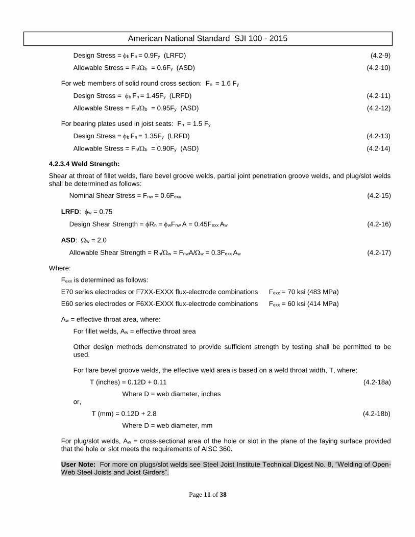
Design Stress = b Fn = 0.9Fy (LRFD) (4.2-9)
Allowable Stress = Fn/b = 0.6Fy (ASD) (4.2-10) For web members of solid round cross section: Fn = 1.6 Fy
Design Stress = b Fn = 1.45Fy (LRFD) (4.2-11)
Allowable Stress = Fn/b = 0.95Fy (ASD) (4.2-12) For bearing plates used in joist seats: Fn = 1.5 Fy
Design Stress = b Fn = 1.35Fy (LRFD) (4.2-13)
Allowable Stress = Fn/b = 0.90Fy (ASD) (4.2-14)
4.2.3.4 Weld Strength:
Shear at throat of fillet welds, flare bevel groove welds, partial joint penetration groove welds, and plug/slot welds shall be determined as follows:
Nominal Shear Stress = Fnw = 0.6Fexx (4.2-15)
LRFD: w = 0.75
Design Shear Strength = Rn = wFnw A = 0.45Fexx Aw (4.2-16)
ASD: w = 2.0
Allowable Shear Strength = Rn/w = FnwA/w = 0.3Fexx Aw (4.2-17)
Where:
Fexx is determined as follows:
E70 series electrodes or F7XX-EXXX flux-electrode combinations Fexx = 70 ksi (483 MPa)
E60 series electrodes or F6XX-EXXX flux-electrode combinations Fexx = 60 ksi (414 MPa)
Aw = effective throat area, where:
For fillet welds, Aw = effective throat area
Other design methods demonstrated to provide sufficient strength by testing shall be permitted to be used. For flare bevel groove welds, the effective weld area is based on a weld throat width, T, where:
T (inches) = 0.12D + 0.11 (4.2-18a)
Where D = web diameter, inches or,
T (mm) = 0.12D + 2.8 (4.2-18b)
Where D = web diameter, mm
For plug/slot welds, Aw = cross-sectional area of the hole or slot in the plane of the faying surface provided that the hole or slot meets the requirements of AISC 360. User Note: For more on plugs/slot welds see Steel Joist Institute Technical Digest No. 8, “Welding of Open-Web Steel Joists and Joist Girders”.

American National Standard SJI 100 - 2015
Page 12 of 38
Strength of resistance welds and complete-joint-penetration groove or butt welds in tension or compression (only where the stress is normal to the weld axis) shall be equal to the base metal strength:
t = c = 0.90 (LRFD) t = c = 1.67 (ASD)
Design Stress = 0.9 Fy (LRFD) (4.2-19) Allowable Stress = 0.6 Fy (ASD) (4.2-20)
4.3 MAXIMUM SLENDERNESS RATIOS
The slenderness ratios, 1.0/r and 1.0s /r of members as a whole or any component part shall not exceed the values given in Table 4.3-1, Part A.
4.3.1 Effective Slenderness Ratios: The effective slenderness ratio, k/r to be used in calculating the nominal stresses, Fcr and F’e, is the largest value as determined from Table 4.3-1, Part B and Part C, and modified where required with equation 4.3-1. The effective length k shall be taken as 1.0 for all components in Joist Girders. 4.3.2 Compressive Members: In compression members where fillers or ties are used, they shall be spaced so that
the s/rz ratio of each component does not exceed the governing /r ratio of the member as a whole. The terms used in Table 4.3-1 shall be defined as follows:
= length center-to-center of panel points, except = 36 inches (914 millimeters) for calculating /ry of the top chord member for joists, and for Joist Girders this distance shall be the unbraced length between joists which are positively attached to the top chord, in. (mm).
s = maximum length center-to-center between panel point and filler (tie), or between adjacent fillers (ties), in. (mm).
rx = member radius of gyration about the horizontal axis of the joist or Joist Girder cross section, in. (mm).
ry = member radius of gyration about the vertical axis of the joist or Joist Girder cross section, in. (mm).
rz = least radius of gyration of a member component, in. (mm).
Compression web members shall be those web members subject to compressive axial loads under gravity loading. 4.3.3 Tension Members: Tension web members shall be those web members subject to tension axial loads under gravity loading, and which shall be permitted to be subject to compressive axial loads under alternate loading conditions User Note: An example of a non-gravity alternate loading condition is net uplift. 4.3.4 Top Chords: For top chords, the end panel(s) shall be the panels between the bearing seat and the first primary interior panel point comprised of at least two intersecting web members.
4.3.5 Built-Up Web Members: For built-up web members composed of two interconnected shapes, where s/rz > 40,
a modified slenderness ratio y m
k
r shall replace
y
k
r in equations 4.2-5, 4.2-6, and 4.2-7, where:
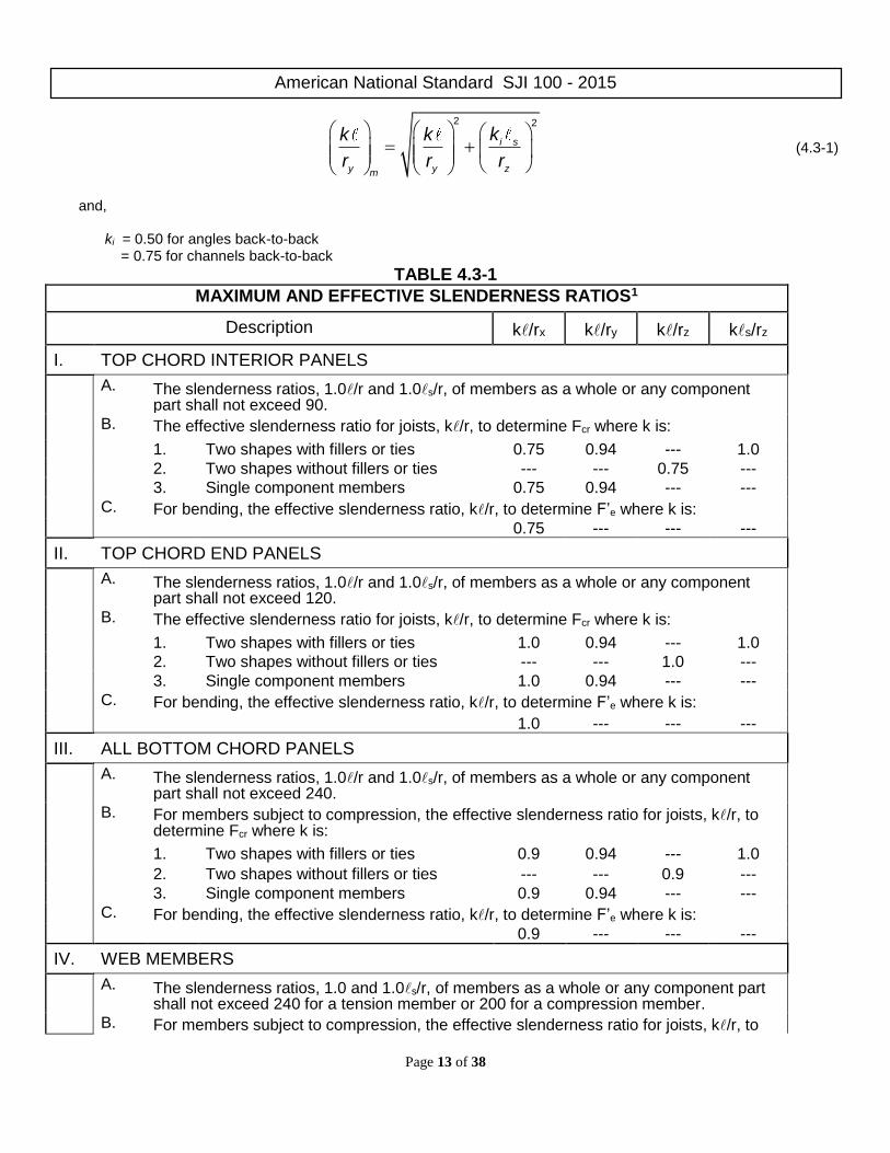
American National Standard SJI 100 - 2015
Page 13 of 38
2 2
i s
y y zm
kk k
r r r (4.3-1)
and,
ki = 0.50 for angles back-to-back
= 0.75 for channels back-to-back
TABLE 4.3-1
MAXIMUM AND EFFECTIVE SLENDERNESS RATIOS1
Description k/rx k/ry k/rz ks/rz
I. TOP CHORD INTERIOR PANELS
A. The slenderness ratios, 1.0/r and 1.0s/r, of members as a whole or any component part shall not exceed 90.
B. The effective slenderness ratio for joists, k/r, to determine Fcr where k is:
1. Two shapes with fillers or ties 0.75 0.94 --- 1.0
2. Two shapes without fillers or ties --- --- 0.75 ---
3. Single component members 0.75 0.94 --- ---
C. For bending, the effective slenderness ratio, k/r, to determine F’e where k is:
0.75 --- --- ---
II. TOP CHORD END PANELS
A. The slenderness ratios, 1.0/r and 1.0s/r, of members as a whole or any component part shall not exceed 120.
B. The effective slenderness ratio for joists, k/r, to determine Fcr where k is:
1. Two shapes with fillers or ties 1.0 0.94 --- 1.0
2. Two shapes without fillers or ties --- --- 1.0 ---
3. Single component members 1.0 0.94 --- ---
C. For bending, the effective slenderness ratio, k/r, to determine F’e where k is:
1.0 --- --- ---
III. ALL BOTTOM CHORD PANELS
A. The slenderness ratios, 1.0/r and 1.0s/r, of members as a whole or any component part shall not exceed 240.
B. For members subject to compression, the effective slenderness ratio for joists, k/r, to determine Fcr where k is:
1. Two shapes with fillers or ties 0.9 0.94 --- 1.0
2. Two shapes without fillers or ties --- --- 0.9 ---
3. Single component members 0.9 0.94 --- ---
C. For bending, the effective slenderness ratio, k/r, to determine F’e where k is:
0.9 --- --- ---
IV. WEB MEMBERS
A. The slenderness ratios, 1.0 and 1.0s/r, of members as a whole or any component part shall not exceed 240 for a tension member or 200 for a compression member.
B. For members subject to compression, the effective slenderness ratio for joists, k/r, to

American National Standard SJI 100 - 2015
Page 14 of 38
determine Fcr where k is:
1. Two shapes with fillers or ties 0.75 1.0 --- 1.0
2. Two shapes without fillers or ties --- --- 1.0 ---
3. Single component members 0.75 0.9* --- ---
*For end tension web members subject to compression, k shall equal 0.8
(1) The effective length k shall equal 1.0 for all components of Joist Girders.
4.4 MEMBERS
4.4.1 Chords
The joist and Joist Girder bottom chord shall be designed as an axially loaded tension member.
For Joist Girders, the radius of gyration of the bottom chord about its vertical axis shall not be less than /240 where
is the distance between lines of bracing. The radius of gyration of a Joist Girder top chord about the vertical axis shall not be less than Span/575. For steel joists, the radius of gyration of the top chord about its vertical axis shall not be less than the results of equation 4.4-1 or 4.4-2:
j
y br j
dr 124+0.67d +28
L
, in. (4.4-1a)
j
y br j
dr 124+0.026d +0.34
L, mm (4.4-1b)
or,
y br
r 170 (4.4-2)
Where:
dj is the steel joist depth, in. (mm)
L is the joist span length, ft. (m)
ry is the radius of gyration of the top chord about the vertical axis of the joist cross section, in. (mm)
br is the spacing in inches (millimeters) between lines of bridging as specified in Section 5.5.3.1.
A steel joist top chord shall be considered as laterally braced by the floor slab or roof deck provided the requirements of Section 5.9 are met. A Joist Girder top chord shall be considered as laterally braced by the steel joists provided positive attachment is made. The outstanding part of the top chord member shall be designed such that the allowable reaction from a single joist shall not exceed equation 4.4-3 or 4.4-4:
Pp and Pp (1.6 – fau/QFy) (LRFD, = 0.9) (4.4-3)
Pp/and Pp/ (1.6 – fa/QFy) (ASD, = 1.67) (4.4-4)
Where:
Fy = Specified minimum yield strength, ksi (MPa)
Pp = Plastic failure mode = [(t2Fy)/[2(b-k)]][g+5.66(b-k)], kips (N)
Q = Form factor defined in Section 4.2.3.2
b = width of the outstanding part of the top chord member, in. (mm)
American National Standard SJI 100 - 2015
Page 15 of 38
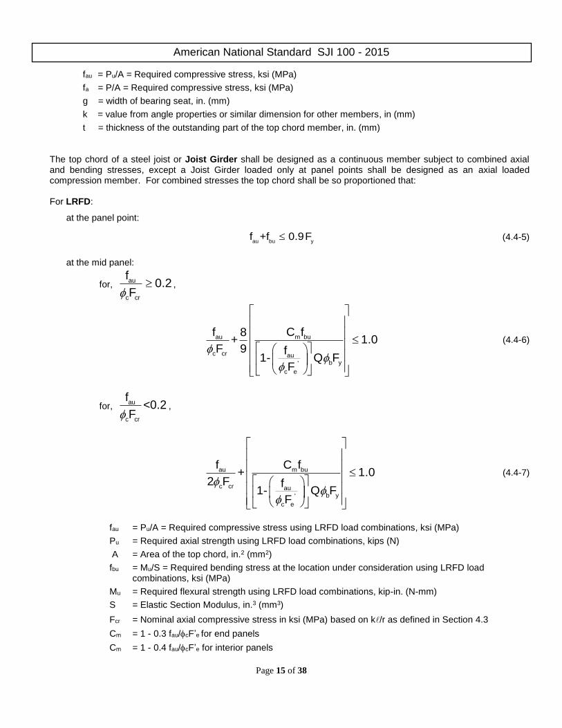
fau = Pu/A = Required compressive stress, ksi (MPa)
fa = P/A = Required compressive stress, ksi (MPa)
g = width of bearing seat, in. (mm)
k = value from angle properties or similar dimension for other members, in (mm)
t = thickness of the outstanding part of the top chord member, in. (mm)
The top chord of a steel joist or Joist Girder shall be designed as a continuous member subject to combined axial and bending stresses, except a Joist Girder loaded only at panel points shall be designed as an axial loaded compression member. For combined stresses the top chord shall be so proportioned that:
For LRFD:
at the panel point:
au bu yf +f 0.9F (4.4-5)
at the mid panel:
for,
au
c cr
f0.2
F,
au m bu
c cr aub y'
c e
f C f8+ 1.0
F 9 f1- Q F
F
(4.4-6)
for,
au
c cr
f<0.2
F,
au m bu
c cr aub y'
c e
f C f+ 1.0
2 F f1- Q F
F
(4.4-7)
fau = Pu/A = Required compressive stress using LRFD load combinations, ksi (MPa)
Pu = Required axial strength using LRFD load combinations, kips (N)
A = Area of the top chord, in.2 (mm2)
fbu = Mu/S = Required bending stress at the location under consideration using LRFD load combinations, ksi (MPa)
Mu = Required flexural strength using LRFD load combinations, kip-in. (N-mm)
S = Elastic Section Modulus, in.3 (mm3)
Fcr = Nominal axial compressive stress in ksi (MPa) based on k/r as defined in Section 4.3
Cm = 1 - 0.3 fau/cF’e for end panels
Cm = 1 - 0.4 fau/cF’e for interior panels

American National Standard SJI 100 - 2015
Page 16 of 38
c
b
Q = Form factor defined in Section 4.2.3.2
= Resistance factor for compression = 0.9
= Resistance factor for flexure = 0.9
Fy = Specified minimum yield strength, ksi (MPa)
F′e =
2
2
x
E
k /r, ksi (MPa),
where is the length, k is the effective length factor, and rx is the corresponding radius of gyration of the member as defined in Section 4.3
E = Modulus of elasticity, 29,000 ksi (200,000 MPa)
For ASD:
at the panel point:
a b yf +f 0.6F (4.4-8)
at the mid panel:
for, a
a
f0.2
F,
a m b
a ab
e
f C f8+ 1.0
F 9 1.67f1- QF
F'
(4.4-9)
for a
a
f<0.2
F,
a m b
a ab
e
f C f+ 1.0
2F 1.67f1- QF
F'
(4.4-10)
fa = P/A required compressive stress using ASD load combinations, ksi (MPa)
A = Area of the top chord, in.2 (mm2)
P = Required axial strength using ASD load combinations, kips (N)
fb = M/S = required bending stress at the location under consideration using ASD load combinations, ksi (MPa)
S = Elastic Section Modulus, in.3 (mm3)
M = Required flexural strength using ASD load combinations, k-in. (N-mm)
Fa = Allowable axial compressive stress based on k/r as defined in Section 4.3; 0.6Fcr, ksi (MPa)
Fb = Allowable bending stress; 0.6Fy, ksi (MPa)

American National Standard SJI 100 - 2015
Page 17 of 38
Cm = 1 - 0.50 fa/F’e for end panels
Cm = 1 - 0.67 fa/F’e for interior panels Q = Form factor defined in Section 4.2.3.2
F′e =
2
2
x
E
k /r, ksi (MPa),
where is the length, k is the effective length factor, and rx is the corresponding radius of gyration of the member as defined in Section 4.3
E = Modulus of elasticity, 29,000 ksi (200,000 MPa)
The top chord and bottom chord shall be designed such that at each joint complies with equation 4.4-11 or 4.4-12:
fvmod ≤ vFn (LRFD, v = 1.00) (4.4-11)
fvmod ≤ Fn/v (ASD, v = 1.50) (4.4-12)
Fn = nominal shear stress = 0.6Fy, ksi (MPa)
ft = axial stress = P/A, ksi (MPa)
fv = shear stress = V/bt, ksi (MPa)
fvmod = modified shear stress = 2 212 t v
4f + f
b = length of vertical part(s) of cross section, in. (mm)
t = thickness of vertical part(s) of cross section, in. (mm)
It shall not be necessary to design the top chord and bottom chord for the modified shear stress, fvmod, where a round bar web member is continuous through a joint. The minimum required shear of section 4.4.2 (25 percent of the maximum end reaction) shall not be required when evaluating Equation 4.4-11 or 4.4-12. KCS Joist, K-Series, chords shall be designed for a flat positive bending moment envelope where the moment capacity is constant at all interior panels. The top chord end panel(s) shall be designed for an axial load based on the force in the first tension web resulting from the specified shear. A uniform load of 550 plf (8020 N/m) in ASD or 825 plf (12030 N/m) in LRFD shall be used to check bending in the end panel(s). The top chord interior panels shall be designed for an axial stress resulting from the constant moment capacity plus the bending stress. The bending stress shall be determined from the smaller uniform load derived from the constant moment and constant shear, not to exceed 550 plf (ASD) or 825 (LRFD). The constant moment and shear shall be those values as listed in the Standard Load Table for KCS Open Web Steel Joists.
4.4.2 Web
The vertical shears to be used in the design of the web members shall be determined by including all loads, but such vertical shears shall be not less than 25 percent of the maximum end reaction from the design load combinations.
4.4.2.1 Redundant Web Members: Redundant web members used in modified Warren type web systems shall be designed to resist the gravity loads supported by the member plus an additional axial load of ½ of 1.0 percent of the top chord axial force. For a Joist Girder, this total axial load shall not be less than 2 percent of the top chord axial force. 4.4.2.2 Joist Girders: For Joist Girders, the tension web members shall be designed to resist at least 25 percent of their axial force in compression. 4.4.2.3 KCS Joist Web Forces: KCS Joist web forces shall be determined based on a flat shear envelope, and the following:

American National Standard SJI 100 - 2015
Page 18 of 38
a) All webs shall be designed for a vertical shear equal to the specified shear capacity. b) All webs shall be designed for 100 percent stress reversal except for the first tension web which remains
in tension under all simple span gravity loads. 4.4.2.4 Single Component Web Member: In those cases where a single component web member is attached to the outside of the stem of a tee or double angle chord or any other orientation of a single web member which creates an out-of-plane moment, the web member design shall account for the stresses due to eccentricity.
4.4.2.4.1 Uncrimped Single Angle Web Members For 1 inch uncrimped single angle web members where one leg is placed flat against one chord member in the gap, the resulting eccentricities and the effects in loading shall be considered in the design. A minimum of 50 percent of the required weld shall be deposited to each chord angle. For angles subjected to tensile loading, the following requirements shall be met:
For LRFD: combined axial and bending stresses shall be proportioned in accordance with Eq. 4.4-5.
For ASD: combined axial and bending stresses shall be proportioned in accordance with Eq. 4.4-8.
For angles subjected to compression loading, the following requirements shall be met:
For LRFD:
at the panel point, combined axial and bending stresses shall be proportioned in accordance with Eq. 4.4-5.
at the mid length, the strength shall meet Eqs. 4.4-6 or 4.4-7, and 4.4-13:
au
c crz
f1.0
F (4.4-13)
where
fau = Pu/A = Required tensile or compressive stress, ksi (MPa)
Pu = Required axial strength using LRFD load combinations, kips (N)
A = Area of the uncrimped angle web, in.2, (mm2)
fbu = Mu/S = required bending stress, ksi (MPa)
Mu = Required flexural strength =
y
2
gapchordP5.0 u , kip-in. (N-mm)
S = Minimum Elastic Section Modulus, in.3 (mm3)
Fcr = Fcrx, ksi (MPa)
Fcrx = Nominal axial compressive stress in ksi (MPa) based on k/rx,
where is the length, k is the effective length factor, and rx is the corresponding radius of gyration of the member as defined in Section 4.3
Fcrz = Nominal axial compressive stress in ksi (MPa) based on k/rz where k = 1.0
Cm = 1.0

American National Standard SJI 100 - 2015
Page 19 of 38
Fy = Specified minimum yield strength, ksi (MPa)
eF =
2
2
x
E
k r , ksi (MPa)
Q = Form factor defined in Section 4.2.3.2
For ASD:
at the panel point, combined axial and bending stresses shall be proportioned in accordance with Eq. 4.4-8.
at the mid length the strength shall meet Eqs. 4.4-9 or 4.4-10, and 4.4-14:
a
az
f1.0
F (4.4-14)
where
fa = P/A = Required tensile or compressive stress, ksi (MPa)
P = Required axial strength using ASD load combinations, kips (N)
A = Area of the uncrimped angle web, in.2, (mm2)
fb = M/S = required bending stress, ksi (MPa)
S = Minimum Elastic Section Modulus, in.3 (mm3)
M = Required flexural strength =
y
2
gapchordP5.0 , kip-in. (N-mm)
Fa = Fax, ksi (MPa)
Fax = Nominal axial compressive stress in ksi (MPa) based on k/rx,
where is the length, k is the effective length factor, and rx is the corresponding radius of gyration of the member as defined in Section 4.3
Faz = Nominal axial compressive stress in ksi (MPa) based on K/rz, where k = 1.0
Fb = Allowable bending stress; 0.6Fy, ksi (MPa)
Alternate methods of design shall be permitted provided they provide strength equal to or greater than those given. Alternate design procedures shall be submitted to the Steel Joist Institute’s consulting engineer for approval.
4.4.3 Fillers and Ties Fillers or ties added on chord or web compression members shall be designed and connected for a force equal to 2% of the required member axial force. 4.4.4 Joist and Joist Girder Extensions
Joist and Joist Girder extensions shall be designated as one of three extension types, as follows: top chord extensions (TCX), extended ends, or full depth cantilevers.
American National Standard SJI 100 - 2015
Page 20 of 38
Design criteria for joist extensions shall be specified using one of the following methods:
a) A joist top chord extension (TCX), extended end, or full depth cantilevered end shall be designed for the load from the Standard Load Tables based on the design length and designation of the specified joist. In the absence of other design information, the joist manufacturer shall design the joist extension for this loading as a default.
b) A loading diagram shall be provided for the joist extension, extended end, or full depth cantilevered end. The
diagram shall include the magnitude and location of the loads to be supported, as well as the applicable load combinations.
c) 2½” deep steel joist extensions shall be permitted to be specified using extension designations found in the
Top Chord Extension Load Table (S Type) for TCXs or the Top Chord Extension Load Table (R Type) for extended ends.
Any deflection requirements or limits due to the accompanying loads and load combinations on the steel joist or Joist Girder extension shall be provided by the specifying professional, regardless of the method used to specify the extension. Unless otherwise specified, the joist manufacturer shall check the extension for the specified deflection limit under uniform live load acting simultaneously on both the joist base span and the extension.
The joist manufacturer shall consider the effects of steel joist or Joist Girder extension loading on the base span of the steel joist or Joist Girder. This shall include carrying the design bending moment due to the loading on the extension into the top chord end panel(s), and the effect on the overall steel joist or Joist Girder chord and web axial forces. In the case of a K-Series Standard Type ‘R’ Extended End or ‘S’ TCX, the design bending moment shall be determined by the tabulated extension section modulus (S) multiplied by the appropriate allowable (ASD) or design (LRFD) flexural stress.
Bracing of extensions shall be clearly indicated on the structural drawings.
4.5 CONNECTIONS
4.5.1 Methods
Member connections and splices shall be made by attaching the members to one another by arc or resistance welding or other accredited methods in accordance with the following:
a) Welded Connections
1) Selected welds shall be inspected visually by the manufacturer. Prior to this inspection, weld slag shall be removed.
2) Cracks shall be repaired.
3) Thorough fusion shall exist between weld and base metal for the required design length of the weld; such fusion shall be verified by visual inspection.
4) Unfilled weld craters shall not be included in the design length of the weld.
5) Undercut shall not exceed 1/16 inch (2 mm) for welds oriented parallel to the principal stress.
6) The sum of surface (piping) porosity diameters shall not exceed 1/16 inch (2 mm) in any 1 inch (25 mm) of design weld length.
7) Weld spatter that does not interfere with paint coverage shall be considered acceptable.
b) Welded Connections for Crimped-End Angle Web Members 1) The connection of each end of a crimped angle web member to each side of the chord shall consist of a
weld group made of more than a single line of weld. The design weld length shall include, at minimum, an end return of two times the nominal weld size.
American National Standard SJI 100 - 2015
Page 21 of 38
c) Welding Program
1) Manufacturers shall have a program for establishing weld procedures and operator qualification, and for weld sampling and testing.
User Note: For more information on welding, see Steel Joist Institute Technical Digest 8 - Welding of Open Web Steel Joists and Joist Girders.
d) Weld Inspection by Outside Agencies (See Section 5.14)
1) The agency shall arrange for visual inspection to determine that welds meet the acceptance standards of Section 4.5.1.
User Note: Ultrasonic, X-ray, and magnetic particle testing are inappropriate for joists due to the configurations of the components and welds.
4.5.2 Strength
4.5.2.1 Joint Connections: Joint connections shall develop the maximum force due to any of the design loads, but not less than 50 percent of the strength of the member in tension or compression, whichever force is the controlling factor in the selection of the member.
4.5.2.2 Shop Splices: Shop splices shall be permitted to occur at any point in chord or web members. Splices shall be designed for the member force, but not less than 50 percent of the member strength. All component parts comprising the cross section of the chord or web member (including reinforcing plates, rods, etc.) at the point of the splice, shall develop an ultimate tensile force of at least 1.2 times the product of the yield strength and the full design area of the chord or web. The “full design area” shall be defined as the minimum required area such that the required stress will be less than the design (LRFD) or allowable (ASD) stress.
4.5.3 Field Splices
Field Splices shall be designed by the manufacturer and shall be either bolted or welded. Splices shall be designed for the member force, but not less than 50 percent of the member strength.
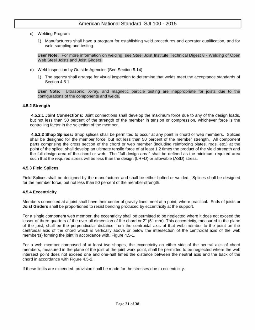
4.5.4 Eccentricity
Members connected at a joint shall have their center of gravity lines meet at a point, where practical. Ends of joists or Joist Girders shall be proportioned to resist bending produced by eccentricity at the support.
For a single component web member, the eccentricity shall be permitted to be neglected where it does not exceed the lesser of three-quarters of the over-all dimension of the chord or 2” (51 mm). This eccentricity, measured in the plane of the joist, shall be the perpendicular distance from the centroidal axis of that web member to the point on the centroidal axis of the chord which is vertically above or below the intersection of the centroidal axis of the web member(s) forming the joint in accordance with. Figure 4.5-1. For a web member composed of at least two shapes, the eccentricity on either side of the neutral axis of chord members, measured in the plane of the joist at the joint work point, shall be permitted to be neglected where the web intersect point does not exceed one and one-half times the distance between the neutral axis and the back of the chord in accordance with Figure 4.5-2. If these limits are exceeded, provision shall be made for the stresses due to eccentricity.
American National Standard SJI 100 - 2015
Page 22 of 38
Figure 4.5-1 Figure 4.5-2 4.6 CAMBER Steel joists and Joist Girders 100’-0” or less shall have a manufactured camber in accordance with Table 4.6-1:
TABLE 4.6-1
TOP CHORD LENGTH APPROXIMATE CAMBER
20'-0″ (6096 mm) 1/4″ (6 mm)
30'-0″ (9144 mm) 3/8″ (10 mm)
40'-0″ (12192 mm) 5/8″ (16 mm)
50'-0″ (15240 mm) 1″ (25 mm)
60'-0″ (18288 mm) 1 1/2″ (38 mm)
70'-0″ (21336 mm) 2″ (51 mm)
80'-0″ (24384 mm) 2 3/4″ (70 mm)
90'-0″ (27432 mm) 3 1/2″ (89 mm)
100'-0″ (30480 mm) 4 1/4″ (108 mm)
For lengths exceeding 100’-0”, manufactured camber equal to Span/300 shall be used. User Note: The specifying professional shall give consideration to coordinating this approximate camber with adjacent framing. 4.7 VERIFICATION OF DESIGN AND MANUFACTURE User Note: This Section is included as part of this Specification since the verification of design and manufacture is a requirement of any Steel Joist Institute member company in order to be in compliance with this Specification. This Section applies only to a Steel Joist Institute member manufacturer.
4.7.1 Design Calculations
Companies manufacturing any K-Series, LH-Series, DLH-Series Joists or Joist Girders shall submit design data to the Steel Joist Institute, or an independent agency approved by the Steel Joist Institute, for verification of compliance with this Specification. Design data shall be submitted in detail and in the format specified by the Steel Joist Institute. 4.7.2 Tests of Chord and Web Members
American National Standard SJI 100 - 2015
Page 23 of 38
Each manufacturer shall, at the time of design review by the Steel Joist Institute, verify by tests that the design, in accordance with Section 4.1 through Section 4.5, provides the theoretical strength of critical members. Such tests shall be evaluated considering the actual yield strength of the members of the test joists.
Material tests for determining mechanical properties of component members shall be conducted.
4.7.3 Tests of Joints and Connections
Each manufacturer shall, at the time of design review by the Steel Joist Institute, verify by shear tests on representative joints of typical joists that connections will meet the provision of Section 4.5.2. Chord and web members shall be permitted to be reinforced for such tests. 4.7.4 In-Plant Inspections
Each manufacturer shall verify their ability to manufacture K-Series, LH-Series, DLH-Series Joists and Joist Girders through periodic In-Plant Inspections. Inspections shall be performed by an independent agency approved by the Steel Joist Institute. The frequency, manner of inspection, and manner of reporting shall be determined by the Steel Joist Institute. The plant inspections shall not represent a guarantee of the quality of any specific joists; this responsibility shall lie fully and solely with the individual manufacturer.
5.1 USAGE
5.1.1 Scope: This Specification shall apply to any type of structure where floors or roofs are to be supported directly by steel joists installed as hereinafter specified or where steel joists are to be supported directly by Joist Girders installed as hereinafter specified. Where joists or Joist Girders are used other than on simple spans under uniformly distributed loading for joists, or under equal concentrated gravity loading for Joist Girders, as prescribed in Section 4.1, they shall be designed to limit the required stresses to those listed in Section 4.2. The magnitude and location of all loads and forces to be considered in the joist or Joist Girder design shall be provided on the structural drawings. 5.1.2 Continuous Frame Action: Where a rigid connection of the bottom chord is to be made to a column or other structural support, the steel joist or Joist Girder is then no longer simply-supported, and the system shall be investigated for continuous frame action by the specifying professional. The specifying professional shall design the supporting structure, including the design of columns, connections, and moment plates. This design shall account for the stresses caused by lateral forces and the stresses due to connecting the bottom chord to the column or other structural support. The designed detail of a rigid type connection and moment plates shall be shown on the structural drawings by the specifying professional. The moment plates shall be furnished by other than the joist manufacturer. User Note: For further reference concerning continuous frame action and their connections, refer to Steel Joist Institute Technical Digest No. 11, “Design of Lateral Load Resisting Frames Using Steel Joists and Joist Girders”.
5.2 SPAN Except for joist substitutes, the span of a joist or Joist Girder shall not exceed 24 times the depth. Design length shall equal the span minus 4 inches (102 mm) as shown in Figure 5.2-1 “Definition of Span”.
SECTION 5.
APPLICATION

American National Standard SJI 100 - 2015
Page 24 of 38
Figure 5.2-1
DEFINITION OF SPAN
(U. S. Customary Units)
American National Standard SJI 100 - 2015
Page 25 of 38
5.3 DEPTH Steel joists or Joist Girders shall have either parallel chords or a top chord pitch of up to 1/2 inch per foot (1:24). The steel joist or Joist Girder designation depth or nominal depth shall be the depth at mid-span, except for double pitched joists which shall be the depth at the ridge. 5.4 END SUPPORTS Consideration of the reactions, vertical and lateral, shall be taken by the specifying professional in the design of the steel support, or the steel bearing plate on masonry or concrete. The standard location of the end reaction shall be 2” (51 mm) from the end of the span (exclusive of extensions) at each end of the steel joist or Joist Girder as shown in Figure 5.2-1 “Definition of Span”. The standard end reaction location shall require the minimum bearing lengths shown in Table 5.4-1.
TABLE 5.4-1
JOIST SECTION
NUMBER1
STANDARD CLEAR BEARING LENGTH
MINIMUM BEARING LENGTH
ON STEEL
K1-12 4” (102 mm) 2 ½” (64 mm)
LH02-06 6” (152 mm) 2 ½” (64 mm)
LH07-17, DLH10-17, JG 6” (152 mm) 4” (102 mm)
DLH18-25, JG2 6” (152 mm) 6” (152 mm)
(1)Last digit(s) of joist designation shown in Load Table. (2) Joist Girders with a self weight greater than 50 plf.
If the specifying professional requires the end reaction to be located at a distance from the face of support more than the standard clear bearing length values shown in Table 5.4-1 minus 2” (51 mm), the structural drawings shall indicate the required special location of the end reaction. The seat depth shall also be increased to the special minimum bearing seat depth per Table 5.4-3.
5.4.1 Masonry and Concrete
5.4.1.1 Scope: A K-Series, LH-Series, DLH-Series Joist or Joist Girder end supported by masonry or concrete shall bear on steel bearing plates and shall be designed as steel bearing. 5.4.1.2 Bearing Length: The ends of K-Series Joists shall extend a distance of not less than 4 inches (102 mm) over the face of masonry or concrete support unless it is deemed necessary to bear less than 4 inches (102 mm) over the support. The ends of LH-Series, DLH-Series Joists and Joist Girders shall extend a distance of not less than 6 inches (152 mm) over the face of masonry or concrete support unless it is deemed necessary to bear less than 6 inches (152 mm) over the support. 5.4.1.3 Anchorage: K-Series, LH-Series, DLH-Series Joists and Joist Girders shall be anchored to the steel bearing plate per Section 5.7. The steel bearing plate shall be located not more than 1/2 inch (13 mm) from the face of the wall. If the steel bearing plate is located more than 1/2 inch (13 mm) from the face of the wall, or the minimum bearing over the masonry or concrete support cannot be provided as shown in Table 5.4-1, special consideration shall be given to the design of the steel bearing plate and the masonry or concrete by the specifying professional. The steel bearing plate width shall not be less than that shown in Table 5.4-2 perpendicular to the length of the joist. The plate is to be designed by the specifying professional and shall be furnished by other than the joist manufacturer.

American National Standard SJI 100 - 2015
Page 26 of 38
TABLE 5.4-2
JOIST SECTION
NUMBER1 MINIMUM BEARING PLATE WIDTH
K1-12, LH02-06 7” (178 mm)
LH07-17, DLH10-17, JG 9” (229 mm)
DLH18-25, JG2 14” (356 mm)
(1)Last digit(s) of joist designation shown in Load Table. (2) Joist Girders with a self weight greater than 50 plf.
5.4.2 Steel The ends of K-Series, LH-Series, DLH-Series Joists and Joist Girders shall be anchored to the support per Section 5.7.
5.4.3 Bearing Depth The standard non-sloping bearing seat depths shall be as shown in Table 5.4-3. If the steel joist slopes 3/8 inch per foot or greater, the high end bearing seat shall require additional depth due to the slope. User Note: The Steel Joist Institute Code of Standard Practice provides guidance for determining additional seat depth requirements for sloped joists.
TABLE 5.4-3
JOIST SECTION
NUMBER1
STANDARD BEARING
SEAT DEPTH
STANDARD CLEAR BEARING
LENGTH SPECIAL MINIMUM BEARING SEAT DEPTH2
K1-12 2 ½” (64 mm) 4” (102 mm) 0.6 x (RP + 2 ½” (64 mm))
LH02-17, DLH10-17 5” (127 mm) 6” (152 mm) 0.6 x (RP + 4” (102 mm))
DLH18-25 7 ½” (191 mm) 6” (152 mm) 0.6 x (RP + 4“ (102 mm)) + 2 ½” (64 mm)
JG 7 ½” (191 mm) 6” (152 mm) RP + 4” (102 mm)
(1)Last digit(s) of joist designation shown in Load Table. (2) RP is equal to the distance the reaction is to occur from the face of the wall or leading edge of support member. The equation is not applicable for the high end of a sloped joist or Joist Girder.
When the specifying professional requires the steel joist or Joist Girder reaction to occur at or near the centerline of the wall or other support, a special bearing seat depth shall be required and a note shall be placed on the structural drawings identifying where the reaction is to occur. The specified bearing seat depth shall be increased according to Table 5.4-3 to allow for this special requirement.
5.5 BRIDGING or BRACING Joist Girders shall be proportioned such that they can be erected without bridging. Therefore, the following requirements shall be met:
a) The ends of the bottom chord shall be restrained from lateral movement to brace the girder from overturning. For Joist Girders at columns in steel frames, restraint shall be provided by a stabilizer plate on the column.

American National Standard SJI 100 - 2015
Page 27 of 38
b) No other loads shall be placed on the Joist Girder until the steel joists bearing on the Joist Girder are in place and positively attached to the Joist Girder.
User Note: See Section 5.12 for bridging or bracing required for uplift forces. Steel joist top and bottom chord bridging shall be required and shall consist of one or both of either horizontal or diagonal bridging. 5.5.1 Horizontal Bridging
Horizontal bridging lines shall consist of continuous horizontal steel members. The /r ratio of the bridging member
shall not exceed 300, where is the distance in inches (millimeters) between attachments and r is the least radius of gyration of the bridging member.
5.5.2 Diagonal Bridging
Diagonal bridging lines shall consist of cross-bracing with a /r ratio of not more than 200, where is the distance in inches (millimeters) between connections and r is the least radius of gyration of the bracing member. Where cross-
bracing members are connected at their point of intersection, the distance shall be taken as the distance in inches (millimeters) between connections at the point of intersection of the bridging members and the connections to the chords of the joists.
5.5.2.1 Diagonal Erection Bridging
User Note: Joists exhibit varying degrees of stability dependent upon the span, depth, member sizes, self weight and other parameters. Bolted diagonal Erection Bridging which must be installed prior to releasing hoisting cables may be required. Where required as identified below, bolted diagonal Erection Bridging shall be required and shall be in accordance with the following:
(a) For joist spans up through and including 60 feet (18288 mm) in length;
Welded horizontal bridging shall be permitted except where the row of bridging nearest the center is required to be bolted diagonal Erection Bridging as indicated by the Red shaded area in the Load Tables. Hoisting cables shall not be released until this row of bolted diagonal Erection Bridging is completely installed and anchored. Bolted diagonal Erection Bridging shall be provided as required in the SJI Load Tables wherever a standard SJI Section Number designation is specified. For spans 60 feet (18288mm) or less, in the absence of a standard SJI Section Number designation, minimum bolted diagonal Erection Bridging requirements shall be determined by:
1) Matching the joist design to an equivalent standard SJI Section Number designation to determine the
span at which Erection Bridging is needed as designated in the tables; or
2) Using Equation 5.5-1 to determine the joist stability and the need for Erection Bridging.
2 4
2
b b a cW
a
; If ,
actual
u
w
w > 1.00 Erection Bridging is not required. (5.5-1)
2
2 3
24a
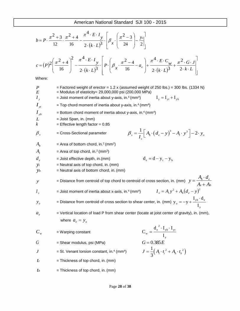
American National Standard SJI 100 - 2015
Page 28 of 38
224
32
32
4
16
42
12
32oy
xLk
yIE
Pb
Lk
JG
Lk
wCE
ax
PLk
yIE
Pc e2
2
32
4
16
42
32
42
16
422
Where:
P = Factored weight of erector = 1.2 x (assumed weight of 250 lbs.) = 300 lbs. (1334 N)
E = Modulus of elasticity= 29,000,000 psi (200,000 MPa)
yI = Joist moment of inertia about y-axis, in.4 (mm4) ybyty III
ytI = Top chord moment of inertia about y-axis, in.4 (mm4)
ybI = Bottom chord moment of inertia about y-axis, in.4 (mm4)
L = Joist Span, in. (mm)
k = Effective length factor = 0.85
x = Cross-Sectional parameter 3 31
2x b e t o
x
A d y A y yI
bA = Area of bottom chord, in.2 (mm2)
tA = Area of top chord, in.2 (mm2)
ed = Joist effective depth, in.(mm) bte yydd
ty = Neutral axis of top chord, in. (mm)
by = Neutral axis of bottom chord, in. (mm)
y = Distance from centroid of top chord to centroid of cross section, in. (mm) b e
t b
A dy
A A
xI = Joist moment of inertia about x-axis, in.4 (mm4) 22 ydAyAI ebtx
oy = Distance from centroid of cross section to shear center, in. (mm)
y
eyb
oI
dIyy
ea = Vertical location of load P from shear center (locate at joist center of gravity), in. (mm),
where oe ya
wC = Warping constant
y
ytyb
2
e
wI
IIdC
G = Shear modulus, psi (MPa) EG 385.0
J = St. Venant torsion constant, in.4 (mm4) 2 21
3t t b b
J A t A t
tt = Thickness of top chord, in. (mm)
bt = Thickness of top chord, in. (mm)
American National Standard SJI 100 - 2015
Page 29 of 38
uw = Ultimate lateral buckling load L
Wwu
12
, plf L
Wwu
, (kN/m)
actualw = Joist self-weight, plf (kN/m)
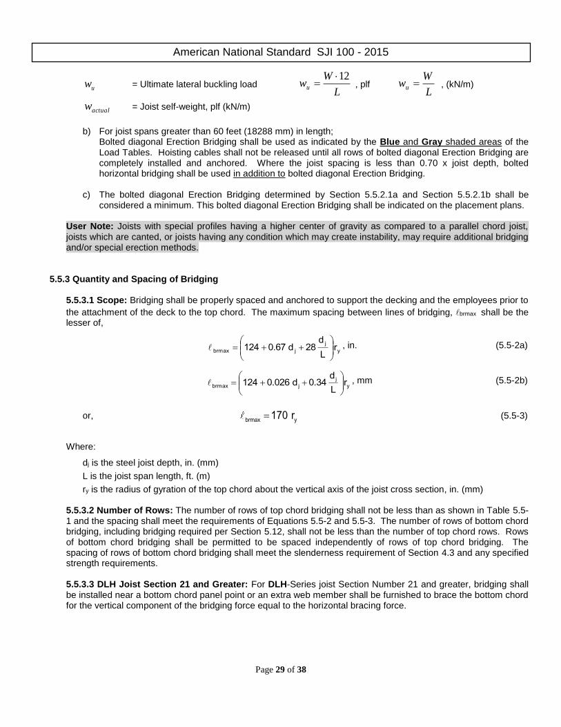
b) For joist spans greater than 60 feet (18288 mm) in length; Bolted diagonal Erection Bridging shall be used as indicated by the Blue and Gray shaded areas of the Load Tables. Hoisting cables shall not be released until all rows of bolted diagonal Erection Bridging are completely installed and anchored. Where the joist spacing is less than 0.70 x joist depth, bolted horizontal bridging shall be used in addition to bolted diagonal Erection Bridging.
c) The bolted diagonal Erection Bridging determined by Section 5.5.2.1a and Section 5.5.2.1b shall be
considered a minimum. This bolted diagonal Erection Bridging shall be indicated on the placement plans. User Note: Joists with special profiles having a higher center of gravity as compared to a parallel chord joist, joists which are canted, or joists having any condition which may create instability, may require additional bridging and/or special erection methods.
5.5.3 Quantity and Spacing of Bridging
5.5.3.1 Scope: Bridging shall be properly spaced and anchored to support the decking and the employees prior to
the attachment of the deck to the top chord. The maximum spacing between lines of bridging, brmax shall be the lesser of,
y
j
jbrmax rL
d28d0.67124
, in. (5.5-2a)
y
j
jbrmax rL
d0.34d0.026124
, mm (5.5-2b)
or, brmax y
170 r (5.5-3)
Where:
dj is the steel joist depth, in. (mm)
L is the joist span length, ft. (m)
ry is the radius of gyration of the top chord about the vertical axis of the joist cross section, in. (mm)
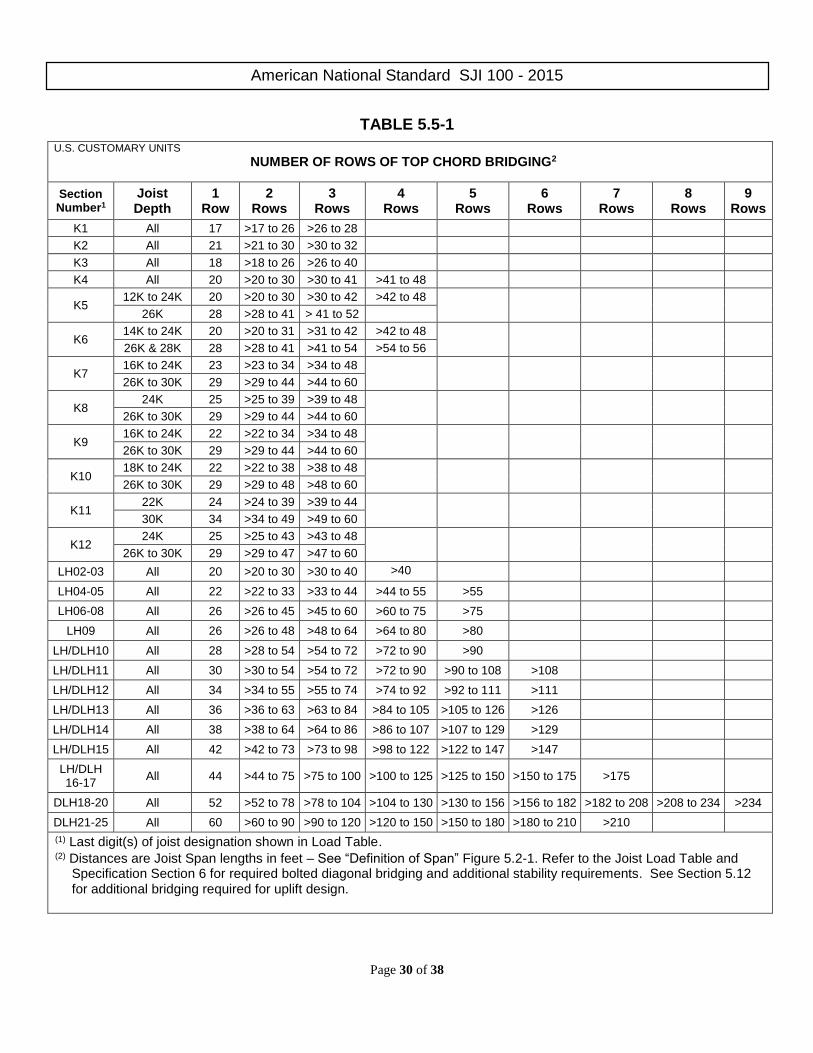
5.5.3.2 Number of Rows: The number of rows of top chord bridging shall not be less than as shown in Table 5.5-1 and the spacing shall meet the requirements of Equations 5.5-2 and 5.5-3. The number of rows of bottom chord bridging, including bridging required per Section 5.12, shall not be less than the number of top chord rows. Rows of bottom chord bridging shall be permitted to be spaced independently of rows of top chord bridging. The spacing of rows of bottom chord bridging shall meet the slenderness requirement of Section 4.3 and any specified strength requirements.
5.5.3.3 DLH Joist Section 21 and Greater: For DLH-Series joist Section Number 21 and greater, bridging shall be installed near a bottom chord panel point or an extra web member shall be furnished to brace the bottom chord for the vertical component of the bridging force equal to the horizontal bracing force.
American National Standard SJI 100 - 2015
Page 30 of 38
TABLE 5.5-1
U.S. CUSTOMARY UNITS
NUMBER OF ROWS OF TOP CHORD BRIDGING2
Section Number1
Joist Depth
1 Row
2 Rows
3 Rows
4 Rows
5 Rows
6 Rows
7 Rows
8 Rows
9 Rows
K1 All 17 >17 to 26 >26 to 28
K2 All 21 >21 to 30 >30 to 32
K3 All 18 >18 to 26 >26 to 40
K4 All 20 >20 to 30 >30 to 41 >41 to 48
K5 12K to 24K 20 >20 to 30 >30 to 42 >42 to 48
26K 28 >28 to 41 > 41 to 52
K6 14K to 24K 20 >20 to 31 >31 to 42 >42 to 48
26K & 28K 28 >28 to 41 >41 to 54 >54 to 56
K7 16K to 24K 23 >23 to 34 >34 to 48
26K to 30K 29 >29 to 44 >44 to 60
K8 24K 25 >25 to 39 >39 to 48
26K to 30K 29 >29 to 44 >44 to 60
K9 16K to 24K 22 >22 to 34 >34 to 48
26K to 30K 29 >29 to 44 >44 to 60
K10 18K to 24K 22 >22 to 38 >38 to 48
26K to 30K 29 >29 to 48 >48 to 60
K11 22K 24 >24 to 39 >39 to 44
30K 34 >34 to 49 >49 to 60
K12 24K 25 >25 to 43 >43 to 48
26K to 30K 29 >29 to 47 >47 to 60
LH02-03 All 20 >20 to 30 >30 to 40 >40
LH04-05 All 22 >22 to 33 >33 to 44 >44 to 55 >55
LH06-08 All 26 >26 to 45 >45 to 60 >60 to 75 >75
LH09 All 26 >26 to 48 >48 to 64 >64 to 80 >80
LH/DLH10 All 28 >28 to 54 >54 to 72 >72 to 90 >90
LH/DLH11 All 30 >30 to 54 >54 to 72 >72 to 90 >90 to 108 >108
LH/DLH12 All 34 >34 to 55 >55 to 74 >74 to 92 >92 to 111 >111
LH/DLH13 All 36 >36 to 63 >63 to 84 >84 to 105 >105 to 126 >126
LH/DLH14 All 38 >38 to 64 >64 to 86 >86 to 107 >107 to 129 >129
LH/DLH15 All 42 >42 to 73 >73 to 98 >98 to 122 >122 to 147 >147
LH/DLH 16-17
All 44 >44 to 75 >75 to 100 >100 to 125 >125 to 150 >150 to 175 >175
DLH18-20 All 52 >52 to 78 >78 to 104 >104 to 130 >130 to 156 >156 to 182 >182 to 208 >208 to 234 >234
DLH21-25 All 60 >60 to 90 >90 to 120 >120 to 150 >150 to 180 >180 to 210 >210
(1) Last digit(s) of joist designation shown in Load Table. (2) Distances are Joist Span lengths in feet – See “Definition of Span” Figure 5.2-1. Refer to the Joist Load Table and
Specification Section 6 for required bolted diagonal bridging and additional stability requirements. See Section 5.12 for additional bridging required for uplift design.

American National Standard SJI 100 - 2015
Page 31 of 38
5.5.4 Sizing of Bridging
Horizontal and diagonal bridging shall be capable of resisting the nominal unfactored horizontal compressive force, Pbr given in Equation 5.5-4.
Pbr = 0.0025 n At Fconstruction , kips (N) (5.5-4)
Where:
n = 8 for horizontal bridging
n = 2 for diagonal bridging
At = cross sectional area of joist top chord, in.2 (mm2)
Fconstruction = assumed ultimate stress in top chord to resist construction loads, determined in accordance with the following:
ksi12.2
r
0.9
EF
2
y
brmax
2
onconstructi
(5.5-5a)
MPa 84.1
r
0.9
EF
2
y
brmax
2
onconstructi
(5.5-5b)
Where:
E = Modulus of Elasticity of steel = 29,000 ksi (200,000 MPa)
and brmax
yr
is determined from Equations 5.5-2 or 5.5-3
The bridging nominal horizontal unfactored compressive forces, Pbr, shall be in accordance with Table 5.5-2.
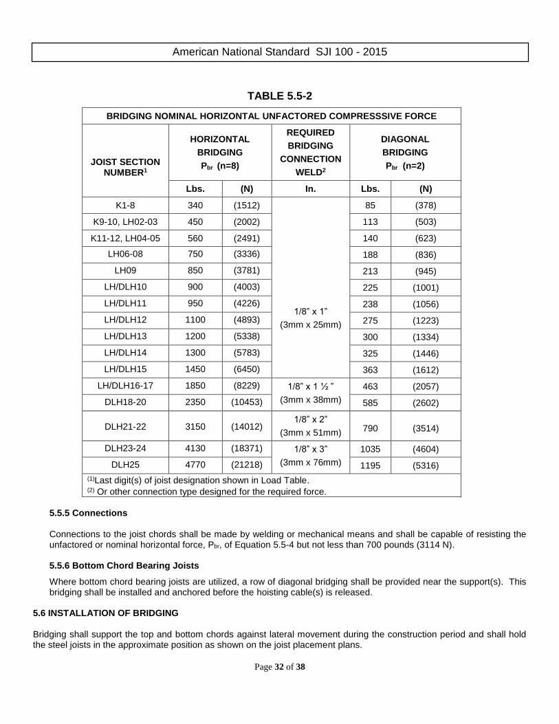
American National Standard SJI 100 - 2015
Page 32 of 38
TABLE 5.5-2
BRIDGING NOMINAL HORIZONTAL UNFACTORED COMPRESSSIVE FORCE
JOIST SECTION NUMBER1
HORIZONTAL
BRIDGING
Pbr (n=8)
REQUIRED
BRIDGING
CONNECTION
WELD2
DIAGONAL
BRIDGING
Pbr (n=2)
Lbs. (N) In. Lbs. (N)
K1-8 340 (1512)
1/8” x 1”
(3mm x 25mm)
85 (378)
K9-10, LH02-03 450 (2002) 113 (503)
K11-12, LH04-05 560 (2491) 140 (623)
LH06-08 750 (3336) 188 (836)
LH09 850 (3781) 213 (945)
LH/DLH10 900 (4003) 225 (1001)
LH/DLH11 950 (4226) 238 (1056)
LH/DLH12 1100 (4893) 275 (1223)
LH/DLH13 1200 (5338) 300 (1334)
LH/DLH14 1300 (5783) 325 (1446)
LH/DLH15 1450 (6450) 363 (1612)
LH/DLH16-17 1850 (8229) 1/8” x 1 ½ ”
(3mm x 38mm)
463 (2057)
DLH18-20 2350 (10453) 585 (2602)
DLH21-22
3150
(14012) 1/8” x 2”
(3mm x 51mm)
790
(3514)
DLH23-24 4130 (18371) 1/8” x 3”
(3mm x 76mm)
1035 (4604)
DLH25 4770 (21218) 1195 (5316)
(1)Last digit(s) of joist designation shown in Load Table. (2) Or other connection type designed for the required force.
5.5.5 Connections
Connections to the joist chords shall be made by welding or mechanical means and shall be capable of resisting the unfactored or nominal horizontal force, Pbr, of Equation 5.5-4 but not less than 700 pounds (3114 N).
5.5.6 Bottom Chord Bearing Joists
Where bottom chord bearing joists are utilized, a row of diagonal bridging shall be provided near the support(s). This bridging shall be installed and anchored before the hoisting cable(s) is released.
5.6 INSTALLATION OF BRIDGING Bridging shall support the top and bottom chords against lateral movement during the construction period and shall hold the steel joists in the approximate position as shown on the joist placement plans.
American National Standard SJI 100 - 2015
Page 33 of 38
The ends of all bridging lines terminating at walls or beams shall be anchored thereto. 5.7 BEARING SEAT ATTACHMENTS 5.7.1 Masonry and Concrete
Ends of K-Series, LH-Series, and DLH-Series Joists and Joist Girders resting on steel bearing plates on masonry or structural concrete shall be attached thereto, as shown in Table 5.7-1, with a minimum of two fillet welds, or with two bolts, or the equivalent.
5.7.2 Steel
Ends of K-Series, LH-Series, and DLH-Series Joists and Joist Girders resting on steel supports shall be attached thereto, as shown in Table 5.7-1, with a minimum of two fillet welds, or with two bolts, or the equivalent. Where K-Series, LH-Series and DLH-Series Joists and Joist Girders are used to provide lateral stability to the supporting member, the final connection shall be made by welding or as designated by the specifying professional.
TABLE 5.7-1
JOIST SECTION NUMBER 1
MINIMUM FILLET WELD MINIMUM BEARING SEAT BOLTS
FOR ERECTION
K1-12 2– 1/8” x 2 1/2” (3 x 64 mm) 2– 1/2” (13 mm) A307
LH02-06 2– 3/16” x 2 1/2” (5 x 64 mm)
LH07-17, DLH10-17, JG 2– 1/4” x 2 1/2” (6 x 64 mm) 2– 3/4” (19 mm) A307
DLH18-25, JG2 2– 1/4” x 4” (6 x 102 mm) 2– 3/4” (19 mm) A325
(1)Last digit(s) of joist designation shown in load table. (2) Joist Girders with a self weight greater than 50 plf.
5.7.3 Uplift
Where uplift forces are a design consideration, roof joists shall be anchored to resist such forces and shall meet the requirements of Section 5.12.
5.8 JOIST SPACING Joists shall be spaced so that the loading on each joist does not exceed the design load (LRFD or ASD) for the particular joist designation and span as shown in the applicable load tables. 5.9 FLOOR AND ROOF DECKS
5.9.1 Material
Floor and roof decks shall be permitted to consist of cast-in-place or pre-cast concrete or gypsum, cold-formed steel, wood, or other suitable material capable of supporting the required load at the specified joist spacing.
5.9.2 Thickness
Cast-in-place slabs shall be not less than 2 inches (51 mm) thick.

American National Standard SJI 100 - 2015
Page 34 of 38
5.9.3 Centering Centering for cast-in-place slabs shall be permitted to be ribbed metal lath, corrugated steel sheets, paper-backed welded wire fabric, removable centering or any other suitable material capable of supporting the slab at the designated joist spacing.
Centering shall not cause lateral displacement or damage to the top chord of joists during installation or removal of the centering or placing of the concrete.
5.9.4 Bearing
Slabs or decks shall bear uniformly along the top chords of the joists.
5.9.5 Attachments
The spacing of attachments along the joist top chord shall not exceed 36 inches (914 mm). Such attachments of the slab or deck to the top chords of joists shall be capable of resisting the forces given in Table 5.9-1.
TABLE 5.9-1
JOIST SECTION NUMBER1
NOMINAL FORCE REQUIRED2
K1-12 100 lbs/ft. (1.46 KN/m)
LH02-04 120 lbs/ft. (1.75 kN/m)
LH05-09 150 lbs/ft. (2.19 kN/m)
LH/DLH10-17 200 lbs/ft. (2.92 kN/m)
DLH18-19 250 lbs/ft. (3.65 kN/m)
DLH20-21 300 lbs/ft. (4.38 kN/m)
DLH22-24 420 lbs/ft. (6.13 kN/m)
DLH25 520 lbs/ft. (7.59 kN/m) (1)Last digit(s) of joist designation shown in Load Table. (2)Nominal bracing force is unfactored.
5.9.6 Wood Nailers
Where wood nailers are used, such nailers in conjunction with deck or slab shall be firmly attached to the top chords of the joists in conformance with Section 5.9.5.
5.9.7 Joist With Standing Seam Roofing or Laterally Unbraced Top Chords
Where the roof systems do not provide lateral stability for the steel joists in accordance with Section 5.9.5 sufficient stability shall be provided to brace the steel joists laterally under the full design load. For this condition, the compression chord design shall include the effects of both the in-plane and out-of-plane buckling of the steel joist (i.e., buckling about the vertical axis of the steel joist cross section). In any case where the attachment requirement of Section 5.9.5 is not achieved, out-of-plane strength shall be achieved by adjusting the bridging spacing and/or increasing the compression chord area and the y-axis radius of gyration. The effective slenderness ratio about the vertical axis equals 0.94 L/ry; where L is the bridging spacing in inches (millimeters) and ry is the radius of gyration of the top chord in inches (millimeters). The maximum bridging spacing shall not exceed that specified in Section 5.5.3. User Note: Some examples of roof systems which may not provide adequate top chord lateral stability may be standing seam roofs, skylights, or other openings which do not provide top chord attachments per Section 5.9.5.

American National Standard SJI 100 - 2015
Page 35 of 38
Horizontal bridging members attached to the compression chords and their anchorages shall be designed for a compressive axial force, Pbr, given in Equation 5.9-1.
Pbr = 0.001nP + 0.004P√n ≥ 0.0025nP, kips (N) (5.9-1)
Where n is the number of joists between end anchors and P is the chord design force in kips (N)
The attachment force between the horizontal bridging member and the compression chord shall be 0.01P. Horizontal bridging attached to the tension chords shall be proportioned so that the slenderness ratio between attachments does not exceed 300. Diagonal bridging shall be proportioned so that the slenderness ratio between attachments does not exceed 200.
5.10 DEFLECTION The deflection due to the design live load shall not exceed the following:
Floors: 1/360 of span. Roofs: 1/360 of span where a plaster ceiling is attached or suspended, or 1/240 of span for all other cases. The specifying professional shall give consideration to the effects of deflection and vibration in the selection of joists. User Note: For further information on vibration, refer to Steel Joist Institute Technical Digest 5, “Vibration of Steel Joist-Concrete Slab Floors". 5.11 PONDING The ponding investigation shall be performed by the specifying professional. User Note: For further reference, refer to Steel Joist Institute Technical Digest 3, “Structural Design of Steel Joist Roofs to Resist Ponding Loads” and AISC 360. 5.12 UPLIFT Where uplift forces due to wind are a design requirement, these forces shall be indicated on the structural drawings in terms of NET uplift in pounds per square foot (Pascals). The structural drawings shall indicate if the net uplift is based upon an LRFD or ASD load combination. When these forces are specified, they shall be considered in the design of joists, Joist Girders, and required bridging or bracing. Wherever uplift due to wind forces is a design consideration, the following shall be required:
a) For joists, a single line of bottom chord bridging shall be provided near the first bottom chord panel points. b) For Joist Girders, if the ends of the bottom chord are not strutted and extended to column stabilizer plates,
bracing shall be provided near the first bottom chord panel points. User Note: For further reference, refer to Steel Joist Institute Technical Digest 6, “Structural Design of Steel Joist Roofs to Resist Uplift Loads.” 5.13 DIAPHRAGMS AND COLLECTORS Where diaphragm collector forces due to wind or seismic forces are a design requirement, these forces shall be indicated on the structural drawings. The structural drawings shall indicate the nominal (unfactored) forces. The structural drawings shall also indicate the Seismic Design Category, and the Seismic Force Resisting System type, and applicable seismic design coefficients. When this data is specified, joist collectors or chords in horizontal diaphragm systems, shall be designed in conformance with the provisions of Section 4 through Section 6. End connections and splices in joists incorporated into Seismic Force Resisting System (SFRS) as horizontal diaphragms as collectors or chords shall adhere
American National Standard SJI 100 - 2015
Page 36 of 38
to the requirements stipulated by the applicable building code. 5.14 INSPECTION Joists shall be inspected by the manufacturer before shipment to verify compliance of materials and workmanship with the requirements of this Specification. User Note: If the purchaser requires an inspection of the steel joists or Joist Girders by someone other than the manufacturer's own inspectors, they shall be permitted to reserve the right to do so in their "Invitation to Bid" or the accompanying "Job Specifications". Arrangements shall be made with the manufacturer for such inspection of the joists or Joist Girders at the manufacturing shop by the purchaser's inspectors at purchaser's expense. 5.15 PARALLEL CHORD SLOPED JOISTS AND JOIST GIRDERS The span of a parallel chord sloped joist or Joist Girder shall be defined by the length along the slope. Minimum depth, load-carrying capacity, and bridging requirements shall be determined by the sloped definition of span. The Load Table capacity shall be the component normal to the joist.
SECTION 6
ERECTION STABILITY
AND HANDLING
As a minimum, erection stability and handling of joists and Joist Girders shall meet the requirements of this Section 6.
User Note: Additional requirements for erection of steel joists and Joist Girders can be found in Steel Joist Institute Technical Digest No. 9, “Handling and Erection of Steel Joists and Joist Girders”. 6.1 STABILITY REQUIREMENTS User Note: It is not recommended that an erector climb on unbridged joists, extreme caution shall be exercised since unbridged joists exhibit some degree of instability under the erector's weight.
a) In steel framing, where joists/Joist Girders are utilized at column lines, the joists/Joist Girder shall be field-bolted at the column. Before hoisting cables are released and before an employee is allowed on the joists/Joist Girder the following conditions shall be met: 1) The seat at each end of the joists/Joist Girder is attached in accordance with Section 5.7. Where a bolted
seat connection is used for erection purposes, as a minimum, the bolts shall be snug tightened. The snug tight condition shall be defined as the tightness that exists where all plies of a joint are in firm contact. This shall be attained by a few impacts of an impact wrench or the full effort of an employee using an ordinary spud wrench.
2) Where stabilizer plates are required the joists/Joist Girder bottom chord shall engage the stabilizer plate.
During the construction period, the contractor shall provide means for the adequate distribution of loads so that the carrying capacity of any joist or Joist Girder is not exceeded.
b) Before an employee is allowed on the steel joist: BOTH ends of joists at columns (or joists designated as column
joists) shall be attached to its supports. For all other joists a minimum of one end shall be attached before the employee is allowed on the joist. The attachment shall be in accordance with Section 5.7.
Where a bolted seat connection is used for erection purposes, as a minimum, the bolts shall be snug tightened.

American National Standard SJI 100 - 2015
Page 37 of 38
The snug tight condition shall be defined as the tightness that exists where all plies of a joint are in firm contact. This shall be attained by a few impacts of an impact wrench or the full effort of an employee using an ordinary spud wrench.
c) On steel joists that do not require erection bridging as shown by either the unshaded area of the Load Tables or
as determined by Section 5.5.2.1, only one employee shall be allowed on the steel joist until all bridging is installed and anchored.
d) Where the span of the steel joist is within the Red shaded area of the Load Table, or in the absence of a standard
SJI Section Number designation and Erection Bridging is required in accordance with Section 5.5.2.1, the following shall apply:
1) The row of bridging nearest the midspan of the steel joist shall be bolted diagonal Erection Bridging; and 2) Hoisting cables shall not be released until this bolted diagonal Erection Bridging is installed and anchored,
unless an alternate method of stabilizing the joist has been provided; and 3) No more than one employee shall be allowed on these spans until all other bridging is installed and anchored.
e) Where the span of the steel joist is within the Blue shaded area of the Load Table, the following shall apply:
1) All rows of bridging shall be bolted diagonal bridging; and 2) Hoisting cables shall not be released until the two rows of bolted diagonal Erection Bridging nearest the third
points of the steel joist are installed and anchored; and 3) No more than two employees shall be allowed on these spans until all bridging is installed and anchored.
f) Where the span of the steel joist is in the Gray shaded area of the Load Table, the following shall apply:
1) All rows of bridging shall be bolted diagonal bridging; and 2) Hoisting cables shall not be released until all bridging is installed and anchored; and 3) No more than two employees shall be allowed on these spans until all other bridging is installed and
anchored.
g) Where permanent bridging terminus points cannot be used during erection, additional temporary bridging terminus points shall be required to provide lateral stability.
h) In the case of bottom chord bearing joists, the ends of the joist shall be restrained laterally per Section 5.5.6
before releasing the hoisting cables. i) After the joist is straightened and plumbed, and all bridging is completely installed and anchored, the ends of the
joists shall be fully connected to the supports in accordance with Section 5.7. 6.2 LANDING AND PLACING LOADS
a) Except as stated in Section 6.2(d), no "construction loads” shall be allowed on the steel joists until all bridging is installed and anchored, and all joist bearing ends are attached.
User Note: For definition of “construction load” see Code of Federal Regulations (CFR), Occupational Safety and Health Administration (OSHA), 29 CFR Part 1926, Safety Standards for Steel Erection; Subpart R - Steel Erection, §1926.751 Definitions; January 18, 2001, Washington, D.C.
b) During the construction period, loads placed on the steel joists shall be distributed so as not to exceed the
capacity of the steel joists.
c) The weight of a bundle of joist bridging shall not exceed a total of 1000 pounds (454 kilograms). The bundle of joist bridging shall be placed on a minimum of three steel joists that are secured at one end. The edge of the bridging bundle shall be positioned within 1 foot (0.30 m) of the secured end.

American National Standard SJI 100 - 2015
Page 38 of 38
d) No bundle of deck shall be placed on steel joists until all bridging has been installed and anchored and all joist bearing ends attached, unless the following conditions are met:
1) The contractor has first determined from a “qualified person” and documented in a site-specific erection plan that the structure or portion of the structure is capable of supporting the load;
2) The bundle of decking is placed on a minimum of three steel joists;
3) The joists supporting the bundle of decking are attached at both ends;
4) At least one row of bridging is installed and anchored;
5) The total weight of the decking does not exceed 4000 pounds (1816 kilograms); and
6) The edge of the bundle of decking is placed within 1 foot (0.30 meters) of the bearing surface of the joist end.
User Note: For definition of “qualified person” see Code of Federal Regulations (CFR), Occupational Safety and Health Administration (OSHA), 29 CFR Part 1926, Safety Standards for Steel Erection; Subpart R - Steel Erection, §1926.751 Definitions; January 18, 2001, Washington, D.C.
e) The edge of the construction load shall be placed within 1 foot (0.30 meters) of the bearing surface of the joist
end. 6.3 FIELD WELDING
All field welding shall be performed in accordance with the structural drawings. Field welding shall not damage the joists or Joist Girders. On cold-formed steel members whose yield strength has been attained by cold working, and whose as-formed strength is used in the design, the total length of weld at any one point shall not exceed 50 percent of the overall developed width of the cold-formed section.
6.4 HANDLING
Particular attention shall be considered for the handling and erection of K-Series, LH-Series, DLH-Series steel joists and Joist Girders. Damage to the joists and accessories shall be avoided. Hoisting cables shall be attached at panel point locations and those locations shall be selected to minimize erection stresses.
Each joist shall be adequately braced laterally before any loads are applied. If lateral support is provided by bridging, the bridging lines as defined in Section 6.1(c), 6.1(d), 6.1(e), and 6.1(f) shall be anchored to prevent lateral movement.
6.5 FALL ARREST SYSYTEMS
Steel joists and Joist Girders shall not be used as anchorage points for a fall arrest system unless written direction to do so is obtained from a “qualified person”.
User Note: For definition of “qualified person” see Code of Federal Regulations (CFR), Occupational Safety and Health Administration (OSHA), 29 CFR Part 1926, Safety Standards for Steel Erection; Subpart R - Steel Erection, §1926.751 Definitions; January 18, 2001, Washington, D.C.