for lenovo cloud network operating system · 20.04.2016 · læs sikkerhedsforskrifterne, før du...
TRANSCRIPT

Lenovo ThinkSystem NE1032T RackSwitch
Installation GuideFor Lenovo Cloud Network Operating System

Important Product Information:
Before using this information and the product it supports, read Appendix B, “Notices“ of this manual. Also read the product Warranty Information document and the Important Notices document included with the product.
Second Edition (January 2018)
© Copyright Lenovo 2018Portions © Copyright IBM Corporation 2014.
LIMITED AND RESTRICTED RIGHTS NOTICE: If data or software is delivered pursuant a General Services Administration “GSA” contract, use, reproduction, or disclosure is subject to restrictions set forth in Contract No. GS-35F-05925.
Lenovo and the Lenovo logo are trademarks of Lenovo in the United States, other countries, or both.

© Copyright Lenovo 2018 Contents 3
Contents
Safety Information . . . . . . . . . . . . . . . . . . . . . . . 7Safety Statements . . . . . . . . . . . . . . . . . . . . . . . . . . . . 9Other Important Safety Notices . . . . . . . . . . . . . . . . . . . . . 13
ThinkSystem NE1032T . . . . . . . . . . . . . . . . . . . . . . 15Port Configuration . . . . . . . . . . . . . . . . . . . . . . . . 15Transceiver Configuration . . . . . . . . . . . . . . . . . . . . . 15Orientation, Airflow, and Redundancy. . . . . . . . . . . . . . . . 15Management . . . . . . . . . . . . . . . . . . . . . . . . . . . 15Additional Features . . . . . . . . . . . . . . . . . . . . . . . . 15
NE1032T Documentation . . . . . . . . . . . . . . . . . . . . . . . 16Notices and Statements in this Document . . . . . . . . . . . . . . 16Related Documentation . . . . . . . . . . . . . . . . . . . . . . 16
Switch Components . . . . . . . . . . . . . . . . . . . . . . . 19Switch Unit . . . . . . . . . . . . . . . . . . . . . . . . . . . . . 20Management Panel . . . . . . . . . . . . . . . . . . . . . . . . . . 21
Mini-USB Serial Console Port . . . . . . . . . . . . . . . . . . . . 21RJ45 Management Port. . . . . . . . . . . . . . . . . . . . . . . 22
RJ45 Management LEDs . . . . . . . . . . . . . . . . . . . . 22Reset Button . . . . . . . . . . . . . . . . . . . . . . . . . . . 22System Status LEDs . . . . . . . . . . . . . . . . . . . . . . . . 23USB Port . . . . . . . . . . . . . . . . . . . . . . . . . . . . . 23
Switching Ports. . . . . . . . . . . . . . . . . . . . . . . . . . . . 24SFP+ Ports . . . . . . . . . . . . . . . . . . . . . . . . . . . . 24SFP+ LEDs . . . . . . . . . . . . . . . . . . . . . . . . . . . . 25
Rear Panel . . . . . . . . . . . . . . . . . . . . . . . . . . . . . . 26Fans . . . . . . . . . . . . . . . . . . . . . . . . . . . . . . . 26Fan LEDs . . . . . . . . . . . . . . . . . . . . . . . . . . . . 26Power Supply . . . . . . . . . . . . . . . . . . . . . . . . . . 27Power LEDs . . . . . . . . . . . . . . . . . . . . . . . . . . . 29
Installing NE1032T Hardware and Options. . . . . . . . . . . . . . 31Before Installing the NE1032T . . . . . . . . . . . . . . . . . . . . . 32
Required Tools . . . . . . . . . . . . . . . . . . . . . . . . . . 33Package Contents . . . . . . . . . . . . . . . . . . . . . . . . . 33Environmental Requirements . . . . . . . . . . . . . . . . . . . . 33Preventing Electric Shock . . . . . . . . . . . . . . . . . . . . . 34Handling Static-Sensitive Devices . . . . . . . . . . . . . . . . . . 36Cabling Guidelines . . . . . . . . . . . . . . . . . . . . . . . . 36
Installing the NE1032T in a Rack . . . . . . . . . . . . . . . . . . . . 37Installing the NE1032T in a Standard Equipment Rack . . . . . . . . . 37Installing the NE1032T in a Lenovo System x or Power Rack . . . . . . 40Installing the NE1032T in a Lenovo iDataPlex Rack . . . . . . . . . . 44Installing the Air-Duct Option . . . . . . . . . . . . . . . . . . . 47

4 Lenovo NE1032T Installation Guide
Installing Port Transceivers . . . . . . . . . . . . . . . . . . . . . . 51Installing an SFP Copper Transceiver . . . . . . . . . . . . . . . . 51Installing an SFP Optical Transceiver . . . . . . . . . . . . . . . . 52Installing an SFP+ Optical Transceiver . . . . . . . . . . . . . . . . 53
Removing and Replacing Components . . . . . . . . . . . . . . . 55Removing Port Transceivers . . . . . . . . . . . . . . . . . . . . . . 56Removing and Replacing a Power Supply Module . . . . . . . . . . . . 57
Removing the Power Supply Module . . . . . . . . . . . . . . . . 58Replacing the Power Supply Module . . . . . . . . . . . . . . . . 59
Removing and Replacing a Fan Module . . . . . . . . . . . . . . . . . 61Removing the Fan Module . . . . . . . . . . . . . . . . . . . . . 61Replacing the Fan Module . . . . . . . . . . . . . . . . . . . . . 62
Removing the NE1032T from a Standard Equipment Rack . . . . . . . . . 63Removing the NE1032T from a Lenovo System x or Power Rack . . . . . . 64Removing the NE1032T from a Lenovo iDataPlex Rack . . . . . . . . . . 66Removing the Air-Duct Option . . . . . . . . . . . . . . . . . . . . . 68Replacing the NE1032T . . . . . . . . . . . . . . . . . . . . . . . . 69
Preparing and Returning the NE1032T . . . . . . . . . . . . . . . . 69Configuring Vital Product Data . . . . . . . . . . . . . . . . . . . 69
Initializing the NE1032T . . . . . . . . . . . . . . . . . . . . . 71System Status LEDs . . . . . . . . . . . . . . . . . . . . . . . . . . 72Connecting to the Switch . . . . . . . . . . . . . . . . . . . . . . . 73
Using the Serial Console Port . . . . . . . . . . . . . . . . . . . . 73Using the Management Port . . . . . . . . . . . . . . . . . . . . 73
Logging Into the Switch . . . . . . . . . . . . . . . . . . . . . . . . 74Default Configuration Files . . . . . . . . . . . . . . . . . . . . . . 75Configuring the Management Interface for Remote Access . . . . . . . . . 76
Out-of-Band Management Interface Configuration . . . . . . . . . . 77In-Band Management Interface Configuration. . . . . . . . . . . . . 77
Updating Firmware . . . . . . . . . . . . . . . . . . . . . . . . . . 78The Boot Management Menu . . . . . . . . . . . . . . . . . . . . . . 79
Boot Recovery Mode. . . . . . . . . . . . . . . . . . . . . . . . 80Recover from a Failed Image Upgrade using TFTP. . . . . . . . . . . 81Recovering from a Failed Image Upgrade using XModem Download . . 83Physical Presence . . . . . . . . . . . . . . . . . . . . . . . . . 85
Troubleshooting . . . . . . . . . . . . . . . . . . . . . . . . 87System LED Is Not Lit . . . . . . . . . . . . . . . . . . . . . . . . . 88Port Link LED Is Not Lit . . . . . . . . . . . . . . . . . . . . . . . . 89Temperature Sensor Warning . . . . . . . . . . . . . . . . . . . . . 90Switch Does Not Initialize (Boot) . . . . . . . . . . . . . . . . . . . . 91

© Copyright Lenovo 2018 Contents 5
Getting Help and Technical Assistance . . . . . . . . . . . . . . . 93
Notices . . . . . . . . . . . . . . . . . . . . . . . . . . . . 95Trademarks . . . . . . . . . . . . . . . . . . . . . . . . . . . . . 97Important Notes . . . . . . . . . . . . . . . . . . . . . . . . . . . 98Recycling Information . . . . . . . . . . . . . . . . . . . . . . . . . 99Particulate Contamination . . . . . . . . . . . . . . . . . . . . . . . 100Telecommunication Regulatory Statement . . . . . . . . . . . . . . . . 101Electronic Emission Notices . . . . . . . . . . . . . . . . . . . . . . 102
Federal Communications Commission (FCC) Statement . . . . . . . . 102Industry Canada Class A Emission Compliance Statement . . . . . . . 102Avis de Conformité à la Réglementation d'Industrie Canada . . . . . . 102Australia and New Zealand Class A Statement . . . . . . . . . . . . 102European Union - Compliance to the Electromagnetic Compatibility Directive 103Germany Class A Statement . . . . . . . . . . . . . . . . . . . . 103Japan VCCI Class A Statement . . . . . . . . . . . . . . . . . . . 104Japan Electronics and Information Technology Industries Association (JEITA) Statement . . . . . . . . . . . . . . . . . . . . . . . . . 104Korea Communications Commission (KCC) Statement . . . . . . . . . 105Russia Electromagnetic Interference (EMI) Class A statement . . . . . . 105People’s Republic of China Class A electronic emission statement . . . . 105Taiwan Class A compliance statement . . . . . . . . . . . . . . . . 105Taiwan BSMI RoHS declaration . . . . . . . . . . . . . . . . . . . 106
Technical Specifications . . . . . . . . . . . . . . . . . . . . 107Physical Characteristics . . . . . . . . . . . . . . . . . . . . . . . . 108Environmental Specifications. . . . . . . . . . . . . . . . . . . . . . 109Power Specifications . . . . . . . . . . . . . . . . . . . . . . . . . 110Switching Performance . . . . . . . . . . . . . . . . . . . . . . . . 111

6 Lenovo NE1032T Installation Guide

© Copyright Lenovo 2018 Safety Information 7
Safety Information
Before installing this product, read the Safety Information.
Antes de instalar este produto, leia as Informações de Segurança.
Prije instalacije ovog produkta obavezno pročitajte Surgonosne Upute.
Před instalací tohoto produktu si přečtěte příručku bezpečnostních instrukcí.
Læs sikkerhedsforskrifterne, før du installerer dette produkt.
Lees voordat u dit product installeert eerst de veiligheidsvoorschriften.
Ennen kuin asennat tämän tuotteen, lue turvaohjeet kohdasta Safety Information.
Avant d'installer ce produit, lisez les consignes de sécurité.
Vor der Installation dieses Produkts die Sicherheitshinweise lesen.’
Πριν εγκαταστήσετε το προϊόν αυτό, διαβάστε τις Πληροφορίες ασφαλείας(safety information).
A termék telepítés előtt olvassa el a Biztonsági előírásokat!
Prima di installare questo prodotto, leggere le Informazioni sulla Sicurezza.
Πред да инсталира овој продукт, прочитајте информацијата за безбедност.
Les sikkerhetsinformasjonen (Safety Information) før du installerer dette produktet.
Przed zainstalowaniem tego produktu, należy zapoznać się z książką “Informacje dotyczace bezpieczeństwa” (Safety Information).
Antes de instalar este produto, leia as Informações sobre Segurança.
Перед установкой продукта прочтитe инcтрyкции по тexникe безопасности.

8 NE1032T Installation Guide
Pred inštaláciou tohto zariadenia si prečítajte Bezpečnostné predpisy.
Pred namestitvijo tega proizvoda preberite Varnostne informacije.
Antes de instalar este producto, lea la información de seguridad.
Läs säkerhetsinformationen innan du installerar den här produkten.
Bu ürünü kurmadan önce güvenlik bilgilerini okuyun.
Youq mwngz yungh canjbinj neix gaxgonq, itdingh aeu doeg aen canjbinj soengq cungj vahgangj ancien suisik.

© Copyright Lenovo 2018 Safety Information 9
Safety StatementsImportant
Each caution and danger statement in this document is labeled with a number. This number is used to cross reference the English-language caution or danger statement with the translated versions of the caution or danger statement in the Safety Information document.
For example, if a caution statement is labeled “Statement 1,” translations for that caution statement are in the Safety Information document under “Statement 1.”
Be sure to read all caution and danger statements in this document before you perform the procedures. Read any additional safety information that comes with the system or optional device before you install the device.
Following is a compilation of the statements found throughout this manual.
Statement 3
CAUTION:
When laser products (such as CD-ROMs, DVD drives, fiber optic devices, or transmitters) are installed, note the following:
Do not remove the covers. Removing the covers of the laser product could result in exposure to hazardous laser radiation. There are no serviceable parts inside the device.
Use of controls or adjustments or performance of procedures other than those specified herein might result in hazardous radiation exposure.
DANGER
Class 1 Laser Product
Laser Klasse 1
Laser Klass 1
Luokan 1 Laserlaite
Appareil À Laser de Classe 1
Some laser products contain an embedded Class 3A or Class 3B laser diode. Note the following.
Laser radiation when open. Do not stare into the beam, do not view directly with optical instruments, and avoid direct exposure to the beam.

10 NE1032T Installation Guide
Statement 5
CAUTION:
The power control button on the device and the power switch on the power supply do not turn off the electrical current supplied to the device. The device also might have more than one power cord. To remove all electrical current from the device, ensure that all power cords are disconnected from the power source.
Statement 8
CAUTION:
Never remove the cover on a power supply or any part that has the following label attached.
Hazardous voltage, current, and energy levels are present inside any component that has this label attached. There are no serviceable parts inside these components. If you suspect a problem with one of these parts, contact a service technician.
Statement 13
DANGER:
1
2
Overloading a branch circuit is potentially a fire hazard and a shock hazard under certain conditions. To avoid these hazards, ensure that your system electrical requirements do not exceed branch circuit protection requirements. Refer to the information that is provided with your device for electrical specifications.

© Copyright Lenovo 2018 Safety Information 11
Statement 25
CAUTION:
This product contains a Class 1M laser. Do not view directly with optical instruments.
Statement 26
CAUTION:
Do not place any object on top of rack-mounted devices.
Statement 31
DANGER Electrical current from power, telephone, and communication cables is hazardous.
To avoid a shock hazard:
Do not connect or disconnect any cables or perform installation, maintenance, or reconfiguration of this product during an electrical storm.
Connect all power cords to a properly wired and grounded power source.
Connect to properly wired power sources any equipment that will be attached to this product.
When possible, use one hand only to connect or disconnect signal cables.
Never turn on any equipment when there is evidence of fire, water, or structural damage.
Disconnect the attached ac power cords, dc power sources, network connections, telecommunications systems, and serial cables before you open the device covers, unless instructed otherwise in the installation and configuration procedures.
Connect and disconnect cables as described in the following table when you install, move, or open covers on this product or attached devices.

12 NE1032T Installation Guide
Statement 37
DANGER
To Connect:
1.Turn OFF all power sources and equipment that is to be attached to this product.
2.Attach signal cables to the product.
3.Attach power cords to the product.
For ac systems, use appliance inlets.
For dc systems, ensure correct polarity of -48 V dc connections: RTN is + and -48 V dc is -. Earth ground should use a two-hole lug for safety.
4.Attach signal cables to other devices.
5.Connect power cords to their sources.
6.Turn ON all the power sources.
To Disconnect:
1.Turn OFF all power sources and equipment that is to be attached to this product. For ac systems, remove all power
cords from the chassis power receptacles or interrupt power at the ac power distribution unit.
For dc systems, disconnect dc power sources at the breaker panel or by turning off the power source. Then, remove the dc cables.
2.Remove the signal cables from the connectors.
3.Remove all cables from the devices.
When you populate a rack cabinet, adhere to the following guidelines:
Always lower the leveling pads on the rack cabinet.
Always install the stabilizer brackets on the rack cabinet.
Always install the heaviest devices in the bottom of the rack cabinet.
Always install devices starting from the bottom of the rack cabinet.
Do not extend multiple devices from the rack cabinet simultaneously, unless the rack-mounting instructions direction you to do so. Multiple devices extended into the service position can cause your rack cabinet to tip.
If you are not using the Lenovo 9308 rack cabinet, securely anchor the rack cabinet to ensure its stability.

© Copyright Lenovo 2018 Safety Information 13
Other Important Safety NoticesThis product is also designed for IT power distribution systems with phase-to-phase voltage of 230V.
This product is not intended for use in the direct field of view at visual display workplaces.
Machinenlärminformations-Verordnung—3. GPSGV, der höchste Shalldruckpegel beträgt 70 dB (A) oder weniger.

14 NE1032T Installation Guide

© Copyright Lenovo 2018 15
Chapter 1. ThinkSystem NE1032T
This Installation Guide provides information about the Lenovo RackSwitch Lenovo ThinkSystem NE1032T RackSwitch (referred to as NE1032T throughout this document).
This Installation Guide provides information about the Lenovo ThinkSystem NE1032T RackSwitch (referred to as NE1032T throughout this document).
The NE1032T uses a wire-speed, non-blocking switching fabric that provides simultaneous wire-speed transport of multiple packets at low latency on all ports.
Port Configuration
The NE1032T contains the following ethernet ports:
Twenty-four 1000/10G BASE-T RJ45 ports
Eight 10 Gigabit Ethernet (GbE) Small Form Pluggable Plus (SFP+) ports
Transceiver Configuration
The 10G BASE-T RJ45 ports, when used in 10 GbE mode, must use CAT6 copper cabling. When used in 1000 base T mode, the ports can be populated with CAT5E copper cabling.
SFP+ ports, when used in 10 GbE mode, can be populated with optical transceiver modules or active or passive Direct-Attach Cables (DACs). When used in legacy 1 GbE mode, the ports can be populated with optical or copper transceiver modules.
Orientation, Airflow, and Redundancy
The NE1032T is 1U in height and can be mounted horizontally or vertically, depending on your application. Mounting options are available for a variety of rack systems.
For superior reliability, the NE1032T uses redundant, hot-swap power supply modules and three hot-swap fan modules. Module options are available for either front-to-rear airflow, or rear-to-front airflow.
Management
You can manage the switch through the local console port, or through a remote network connection, or SNMP-based network management software.
Additional Features
Other features supported on your switch depend on the specific firmware installed. For more information, see the Application Guide and Command Reference for your specific switch and its installed firmware.

16 NE1032T Installation Guide
NE1032T DocumentationThis Installation Guide provides information and instructions for installing the NE1032T, updating the firmware, and solving problems. For other information about configuration and management of the switch, refer to the documents described in “Related Documentation” on page 16.
Notes:
The illustrations in this document might differ slightly from your hardware.
The console output described or referenced in this document might differ slightly from that displayed by your system. Output varies according to the type of Lenovo chassis and the firmware versions and options that are installed.
Notices and Statements in this Document
The following notices and statements are used in this document:
Note: These notices provide important tips, guidance, or advice.
Important: These notices provide information or advice that might help you avoid inconvenient or problem situations.
Attention: These notices indicate potential damage to programs, devices, or data. An attention notice is placed just before the instruction or situation in which damage could occur.
Caution: These statements indicate situations that can be potentially hazardous to you. A caution statement is placed just before the description of a potentially hazardous procedure step or situation.
Danger: These statements indicate situations that can be potentially lethal or extremely hazardous to you. A danger statement is placed just before the description of a potentially lethal or extremely hazardous procedure step or situation.
Related Documentation
Additional or updated product documents may be available from the Lenovo website. Such documents may cover features not described in the original documentation that comes with the switch, or may include technical updates or corrections.
You can obtain up-to-date information on the Lenovo support website:
http://support.lenovo.com/Note: Changes are made periodically to the Lenovo website. Procedures for locating firmware and documentation might vary slightly from what is described in this document.
For information about switch hardware and firmware features, specifications, and standards, including their configuration, see the Application Guide for your specific switch and its installed firmware.

© Copyright Lenovo 2018 Chapter 1: ThinkSystem NE1032T 17
For information about the switch, statistics, and individual configuration parameters, see the Command Reference guide for your specific switch and its installed firmware.
For a list of compatible switch components and options (such as rack-mounting kits, modules, cords, and cables), see the Lenovo Networking Catalog.

18 NE1032T Installation Guide

© Copyright Lenovo 2018 19
Chapter 2. Switch Components
This chapter describes the NE1032T hardware components.

20 NE1032T Installation Guide
Switch UnitThe NE1032T is a 1U rack-mountable GbE switch. You can mount the switch in either the horizontal or vertical orientation.
The following illustrations show the features on the front and rear of the switch.
Figure 1. ThinkSystem NE1032T front panel
Figure 2. ThinkSystem NE1032T management panel detail
Figure 3. ThinkSystem NE1032T rear panel IEC320
Power ConnectorIEC320
Power Connector
Fan Modules Power Supply Modules

© Copyright Lenovo 2018 Chapter 2: Switch Components 21
Management PanelThe following parts comprise the management panel.
Mini-USB Serial Console Port
The mini-USB serial console port on the front management panel is available for switch console management. The port operates using RS-232 serial communications. A compatible console cable kit is included with the switch.
To connect a computer or terminal to the switch using the included kit, first connect the console cable to the mini-USB serial console port on the front panel. Connect one end of the Category 5 patch cable to the RJ45 port on the console cable and the other end of the patch cable to the RJ45-to-DB9 adapter, which then connects to the computer or terminal (see the following illustration).
Figure 4. Mini-USB console cable connections
If using cables other than those from the included cable kit, ensure that they are compatible with the port pin assignments shown in the following tables.
Table 1. Switch mini-USB port connector pin assignments
Pin Number Function
1 No connect
2 SIN (RS-232 Input)
3 SOUT (RS-232 Output)
4 No connect
5 GND (Ground)
To PCTerminal
To Switch Mini-USBConsole Port
RJ45-to-DB9 AdapterCategory 5
Patch CableSwitch
Console Cable

22 NE1032T Installation Guide
RJ45 Management Port
The RJ45 management port on the front panel supports 10/100/1000BASE-T, in-line switch management.
To attach an RJ45 connector to the switch, push the RJ45 cable connector into the port connector until it clicks into place.
To disconnect the RJ45 cable, squeeze the release tab and gently pull the cable connector out of the switch connector.
RJ45 Management LEDsThe RJ45 management port LEDs are oriented as shown in the following figure.
Figure 5. RJ45 management port LEDs
Status LEDs for the RJ45 management port are described in the following table.
Reset Button
The Reset button is recessed within a hole on the front panel. Use a straightened paper clip or similar object to press the Reset button. The Reset button allows technicians to reset the switch as follows:
Normal reset—press and release reset button. The switch will start a forced reload procedure without saving the current configuration. This action is intended for when the switch is unresponsive and needs to be restarted to resume its normal functions.
Table 2. RJ45 status LEDs behavior
LED State Functional Meaning
Link Flashing green Activity
Steady green Link up
Off No link
Speed Steady green 1000 Mbps connection
Off 10 Mbps connection or no link
Speed LEDLink LED

© Copyright Lenovo 2018 Chapter 2: Switch Components 23
System Status LEDs
The following table describes the behavior of the system status LEDs:
Note 1: Support for the stacking feature depends on the installed firmware. To determine whether your switch supports stacking, see the Application Guide for your specific switch and firmware version.
Note 2: If service required is due to a stacking error, this LED flashes or is steady green, depending on its last known good state.
USB Port
The USB port enables you to connect a USB drive to the switch. You can copy files from the switch to the USB drive, or from the USB drive to the switch. You can also start the switch using files on the USB drive.
The supported file system formats for USB drives are FAT32 and NTFS (read-only).Note: When using a NTFS formatted USB drive, copying operations are limited to read-only. Files can be copied from the USB drive to the switch, but copying files to the NTFS formatted USB drive results in failure.
For more information about using the USB drive, see the Lenovo ThinkSystem NE1032T RackSwitch Release Notes.
Table 3. System status LEDs behavior
LED State Functional Meaning
All Off Total power failure.
- Service Steady blue An operational command has been sent to light the LED so that this device can be more readily located.
Flashing blue Service is required due to failure of the general system, its cooling fans, stacking function1 or its power supply. The specific failure is indicated in conjunction with the other system status LEDs.
- Power Steady green Power is OK.
Flashing green Power supply failure or disconnection. Service is required.
- Fans Steady green Fans are OK.
Flashing green Fan failure. Service is required.
- Stacking1 Steady green Device is a Backup/Member in a stack.2
Flashing green Device is the Master in a stack.2
Off Device is not a stacking member.

24 NE1032T Installation Guide
Switching PortsThe NE1032T contains the following switching ports:
Twenty-four 1000/10G BASE-T RJ45 ports
Eight 10GbE Small Form Pluggable Plus (SFP+) ports
For a list of compatible transceivers and DACs, see the Lenovo Networking Catalog.
The switching ports are described in the following sections. For information about ports on the management panel, see “Management Panel” on page 21.
SFP+ Ports
Eight 10 GbE SFP+ ports are available on the front panel. These ports accept supported optical or copper SFP or SFP+ transceivers or DACs. Transceivers must be purchased separately.
Statement 3
CAUTION:
When laser products (such as CD-ROMs, DVD drives, fiber optic devices, or transmitters) are installed, note the following:
Do not remove the covers. Removing the covers of the laser product could result in exposure to hazardous laser radiation. There are no serviceable parts inside the device.
Use of controls or adjustments or performance of procedures other than those specified herein might result in hazardous radiation exposure.
DANGER
Class 1 Laser ProductLaser Klasse 1Laser Klass 1Luokan 1 LaserlaiteAppareil À Laser de Classe 1
Some laser products contain an embedded Class 3A or Class 3B laser diode. Note the following.
Laser radiation when open. Do not stare into the beam, do not view directly with optical instruments, and avoid direct exposure to the beam.

© Copyright Lenovo 2018 Chapter 2: Switch Components 25
SFP+ LEDs
Status LEDs for the SFP+ ports are described in the following table.
Statement 3
CAUTION:
When laser products (such as CD-ROMs, DVD drives, fiber optic devices, or transmitters) are installed, note the following:
Do not remove the covers. Removing the covers of the laser product could result in exposure to hazardous laser radiation. There are no serviceable parts inside the device.
Use of controls or adjustments or performance of procedures other than those specified herein might result in hazardous radiation exposure.
DANGER
Class 1 Laser Product
Laser Klasse 1
Laser Klass 1
Luokan 1 Laserlaite
Appareil À Laser de Classe 1
Table 4. SFP+ port status LED behavior
LED State Functional Meaning
Link/Activity Steady green Link up
Off No link
Flashing green Activity
Some laser products contain an embedded Class 3A or Class 3B laser diode. Note the following.
Laser radiation when open. Do not stare into the beam, do not view directly with optical instruments, and avoid direct exposure to the beam.

26 NE1032T Installation Guide
Rear PanelThe rear panel is composed of the following components.
Fans
For cooling, the rear panel of the NE1032T has three bays for hot-swap fan modules. Three fan modules are required for redundancy. When three fan modules are used, if there is a failure of one of the fans, the switch reports the condition, the other fans continue to run, and the switch continues to operate normally.
You can replace one failed hot-swap fan module while the switch is operating. If a second fan fails, the switch reports the condition and shuts down to prevent overheating.
CAUTION:Be sure to finish the replacement procedure promptly. The switch could overheat if left without cooling for an extended period.
Compatible fan options are listed in the Lenovo Networking Catalog.
Fan operation and internal temperatures are monitored. If the air temperature exceeds a desired threshold, the environmental monitor displays warnings.Note: If a fan fails, the maximum operating temperature drops from +40°C (104°F) to +35°C (95°F).
Fan LEDs
If there is a failure of one or more fans, the front panel Fan LED flashes.
Additional Fan LED indicators are located on the rear panel of the switch, on the individual fan modules.
The following table describes the fan module LED behavior.
Table 5. Fan module status LED behavior
LED State Functional Meaning
On Fan is operational
Off Fan module has no power.
Flashing Fan speed has failed. Replace the fan module.

© Copyright Lenovo 2018 Chapter 2: Switch Components 27
Power Supply
The rear panel of the NE1032T has two bays for hot-swap power supply modules. Each power supply module has an individual IEC 320 C14 power connector. The power cord attaches to a universal grounded AC power source.
Compatible power options are listed in the Lenovo Networking Catalog.
Statement 5
CAUTION:
The power control button on the device and the power switch on the power supply do not turn off the electrical current supplied to the device. The device also might have more than one power cord. To remove all electrical current from the device, ensure that all power cords are disconnected from the power source.
Statement 31
DANGER
1
2
Electrical current from power, telephone, and communication cables is hazardous.
To avoid a shock hazard:
Do not connect or disconnect any cables or perform installation, maintenance, or reconfiguration of this product during an electrical storm.
Connect all power cords to a properly wired and grounded power source.
Connect to properly wired power sources any equipment that will be attached to this product.
When possible, use one hand only to connect or disconnect signal cables.
Never turn on any equipment when there is evidence of fire, water, or structural damage.
Disconnect the attached ac power cords, dc power sources, network connections, telecommunications systems, and serial cables before you open the device covers, unless instructed otherwise in the installation and configuration procedures.
Connect and disconnect cables as described in the following table when you install, move, or open covers on this product or attached devices.
28 NE1032T Installation Guide
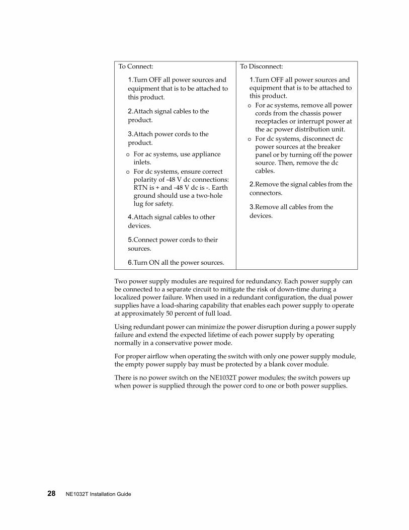
Two power supply modules are required for redundancy. Each power supply can be connected to a separate circuit to mitigate the risk of down-time during a localized power failure. When used in a redundant configuration, the dual power supplies have a load-sharing capability that enables each power supply to operate at approximately 50 percent of full load.
Using redundant power can minimize the power disruption during a power supply failure and extend the expected lifetime of each power supply by operating normally in a conservative power mode.
For proper airflow when operating the switch with only one power supply module, the empty power supply bay must be protected by a blank cover module.
There is no power switch on the NE1032T power modules; the switch powers up when power is supplied through the power cord to one or both power supplies.
To Connect:
1.Turn OFF all power sources and equipment that is to be attached to this product.
2.Attach signal cables to the product.
3.Attach power cords to the product.
For ac systems, use appliance inlets.
For dc systems, ensure correct polarity of -48 V dc connections: RTN is + and -48 V dc is -. Earth ground should use a two-hole lug for safety.
4.Attach signal cables to other devices.
5.Connect power cords to their sources.
6.Turn ON all the power sources.
To Disconnect:
1.Turn OFF all power sources and equipment that is to be attached to this product. For ac systems, remove all power
cords from the chassis power receptacles or interrupt power at the ac power distribution unit.
For dc systems, disconnect dc power sources at the breaker panel or by turning off the power source. Then, remove the dc cables.
2.Remove the signal cables from the connectors.
3.Remove all cables from the devices.
© Copyright Lenovo 2018 Chapter 2: Switch Components 29
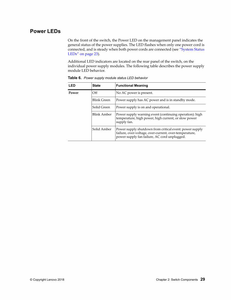
Power LEDs
On the front of the switch, the Power LED on the management panel indicates the general status of the power supplies. The LED flashes when only one power cord is connected, and is steady when both power cords are connected (see “System Status LEDs” on page 23).
Additional LED indicators are located on the rear panel of the switch, on the individual power supply modules. The following table describes the power supply module LED behavior.
Table 6. Power supply module status LED behavior
LED State Functional Meaning
Power Off No AC power is present.
Blink Green Power supply has AC power and is in standby mode.
Solid Green Power supply is on and operational.
Blink Amber Power supply warning event (continuing operation): high temperature, high power, high current, or slow power supply fan.
Solid Amber Power supply shutdown from critical event: power supply failure, over-voltage, over-current, over-temperature, power supply fan failure, AC cord unplugged.

30 NE1032T Installation Guide

© Copyright Lenovo 2018 31
Chapter 3. Installing NE1032T Hardware and Options
This chapter describes how to install the NE1032T hardware and options. The following topics are covered:
“Before Installing the NE1032T” on page 32 How to record important product information Tools required for installation A list of items included in the package Environmental requirements Vital safety information
Installing the switch in one of the supported rack types “Installing the NE1032T in a Standard Equipment Rack” on page 37 “Installing the NE1032T in a Lenovo System x or Power Rack” on page 40
“Installing the Air-Duct Option” on page 47
“Installing Port Transceivers” on page 51Note: For information on removing or replacing installed NE1032T components, see Chapter 4, “Removing and Replacing Components“.
32 NE1032T Installation Guide
Before Installing the NE1032T
Attention: Product information is required in order to register your NE1032T, update its firmware, place a service call, or replace the unit.
Some of the product information labels may be hidden from view once the NE1032T is installed. To prevent the need to remove the switch in order to read required product information, locate and record the information shown on Table 7 prior to installation.
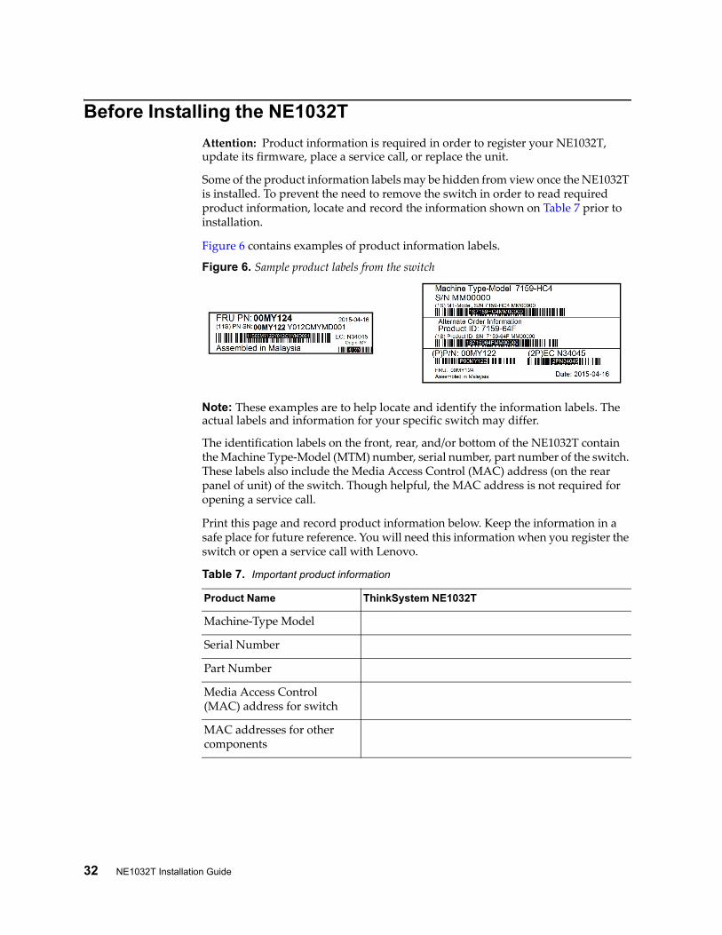
Figure 6 contains examples of product information labels.
Figure 6. Sample product labels from the switch
Note: These examples are to help locate and identify the information labels. The actual labels and information for your specific switch may differ.
The identification labels on the front, rear, and/or bottom of the NE1032T contain the Machine Type-Model (MTM) number, serial number, part number of the switch. These labels also include the Media Access Control (MAC) address (on the rear panel of unit) of the switch. Though helpful, the MAC address is not required for opening a service call.
Print this page and record product information below. Keep the information in a safe place for future reference. You will need this information when you register the switch or open a service call with Lenovo.
Table 7. Important product information
Product Name ThinkSystem NE1032T
Machine-Type Model
Serial Number
Part Number
Media Access Control (MAC) address for switch
MAC addresses for other components

© Copyright Lenovo 2018 Chapter 3: Installing NE1032T Hardware and Options 33
For convenience, once the NE1032T is installed and initialized, you can use the following command in the switch firmware interface to display the product serial number and other required information:
For more information, see “Configuring Vital Product Data” on page 69.
Required Tools
You need the following tools or equipment to install the NE1032T:
Standard flat-blade screwdriver
#2 Phillips screwdriver
Electrostatic discharge wrist strap
Package Contents
The basic NE1032T package contains the following items:
One ThinkSystem NE1032T unit with front-to-rear or rear-to-front airflow
One two-post mounting kit for standard 19” equipment racks: Two mounting brackets Screws to attach brackets to the switch unit Screws to attach the switch unit to the equipment rack
One console cable kit that includes: One Mini-USB to RJ45 console cable One Category 5 patch cable One RJ45 to DB9 adapter
One Important Notices document
One Warranty Information document
For a list of compatible switch components and options (such as rack-mounting kits, modules, cords, and cables), see the Lenovo Networking Catalog.
Environmental Requirements
This section describes the basic environmental requirements for the NE1032T. Make sure the location where you install the switch meets the following requirements:
Install the switch unit in a dry, clean, well-ventilated area.
Provide adequate space in the front and back of the switch unit, to ensure proper air flow.
Make sure that an adequate grounded power supply is within reach of the switch unit.
Make sure that twisted-pair cable is routed away from power lines, fluorescent lighting fixtures and other sources of electrical interference.
NE1032T> display sys-info

34 NE1032T Installation Guide
Preventing Electric Shock
This product does not contain any user-serviceable parts. Do not remove the cover of this device.
The NE1032T AC power module is designed to work with single-phase power systems that have a grounded neutral conductor. For your safety, a power cord with a ground attachment plug is available to order for use with this product. To avoid electrical shock, always use an appropriate power cord and plug with a properly grounded outlet.
Power cords for this product that are used in the United States and Canada are listed by Underwriter's Laboratories (UL) and certified by the Canadian Standards Association (CSA).
For units intended to be operated at 115 volts: Use a UL-listed and CSA-certified cord set consisting of a minimum of 18 AWG, Type SVT or SJT, three-conductor cord, a maximum of 15 feet in length and a parallel blade, grounding-type attachment plug rated 15 amperes, 125 volts.
For units intended to be operated at 230 volts (U.S. use): Use a UL-listed and CSA-certified cord consisting of a minimum of 18 AWG, Type SVT or SJT, three-conductor cord, a maximum of 15 feet in length and a tandem blade, grounding-type attachment plug rated 15 amperes, 250 volts.
For units intended to be operated at 230 volts (outside the U.S.): Use a cord set with a grounding-type attachment plug. The cord set should have the appropriate safety approvals for the country in which the equipment will be installed.
Power cords for this product for a specific country or region are usually available only in that country or region.
Power cord installation should also conform to the recommendations listed in “Cabling Guidelines” on page 36.

© Copyright Lenovo 2018 Chapter 3: Installing NE1032T Hardware and Options 35
Statement 31
DANGER Electrical current from power, telephone, and communication cables is hazardous.
To avoid a shock hazard:
Do not connect or disconnect any cables or perform installation, maintenance, or reconfiguration of this product during an electrical storm.
Connect all power cords to a properly wired and grounded power source.
Connect to properly wired power sources any equipment that will be attached to this product.
When possible, use one hand only to connect or disconnect signal cables.
Never turn on any equipment when there is evidence of fire, water, or structural damage.
Disconnect the attached ac power cords, dc power sources, network connections, telecommunications systems, and serial cables before you open the device covers, unless instructed otherwise in the installation and configuration procedures.
Connect and disconnect cables as described in the following table when you install, move, or open covers on this product or attached devices.
To Connect:
1. Turn OFF all power sources and equipment that is to be attached to this product.
2. Attach signal cables to the product.
3. Attach power cords to the product.
For ac systems, use appliance inlets.
For dc systems, ensure correct polarity of -48 V dc connections: RTN is + and -48 V dc is -. Earth ground should use a two-hole lug for safety.
4. Attach signal cables to other devices.
5. Connect power cords to their sources.
6. Turn ON all the power sources.
To Disconnect:
1. Turn OFF all power sources and equipment that is to be attached to this product.
For ac systems, remove all power cords from the chassis power receptacles or interrupt power at the ac power distribution unit.
For dc systems, disconnect dc power sources at the breaker panel or by turning off the power source. Then, remove the dc cables.
2. Remove the signal cables from the connectors.
3. Remove all cables from the devices.

36 NE1032T Installation Guide
Handling Static-Sensitive Devices
Attention: Static electricity can damage the switch and other electronic devices. To avoid damage, keep static-sensitive devices in their static-protective packages until you are ready to install them.
To reduce the possibility of electrostatic discharge, observe the following precautions:
Limit your movement. Movement can cause static electricity to build up around you.
The use of a grounding system is recommended. For example, wear an electrostatic-discharge wrist strap, if one is available.
Handle the device carefully, holding it by its edges or its frame.
Do not touch solder joints, pins, or exposed printed circuitry.
Do not leave the device where others can handle and damage it.
While the device is still in its static-protective package, touch it to an unpainted metal part of any unpainted metal surface on a grounded rack component in the rack in which you are installing the device, for at least 2 seconds. This drains static electricity from the package and from your body.
Remove the device from its package and install it directly into the switch without setting it down. If it is necessary to set down the device, put it back into its static-protective package. Do not place the device on a switch cover or on a metal surface.
Take additional care when you handle devices during cold weather. Heating reduces indoor humidity and increases static electricity.
Cabling Guidelines
Make sure that all connection cables comply with the following recommendations:
Make sure that the cables and cabling components comply with industry standards.
Dress and affix cables to the rack to minimize the stress on the I/O connectors, connector cages, and cables. If possible, use horizontal and vertical cable managers to minimize obstruction of the airflow and other equipment.
Use wide Velcro straps to reduce pressure points.
Position large or heavy cable bundles under other cable bundles to prevent crushing or stress. Over-bundling, or placing multiple bundles on top of each other, can degrade performance.
Make sure that the radius of any bend does not exceed the vendor recommended minimum bend radius.
Do not stress cables and connectors by applying additional twists, tension beyond load ratings, stapling, or applying nylon tie-wraps with a tie-wrap puller.

© Copyright Lenovo 2018 Chapter 3: Installing NE1032T Hardware and Options 37
Installing the NE1032T in a RackThe NE1032T can be rack-mounted using one of the following mounting kits:
For a standard 19-inch equipment rack, use the 2-post rack mounting brackets and screws included with the switch. Installation instructions begin on page 37.
For a Lenovo System x or Power 4-post rack, use the Lenovo Adjustable 19” 4-Post Rail Kit. This kit must be purchased separately. Installation instructions begin on page 40.
Installing the NE1032T in a Standard Equipment Rack
This section describes how to install the NE1032T in a standard 19-inch equipment rack using the mounting kit included with the switch. For information about mounting the switch in other supported racks, see the appropriate section in this chapter.
The following parts are included in the standard mounting kit.
Attention: The rack-mounting frame may be unable to support the weight of the switch with only the front post mounting brackets (2-post application). If the switch has an undesirable amount of sag, it is recommended to use a 4-post mounting kit.
Attention: For earthquake stability, mount the switch in a 4-post rack.
Table 8. 2-post rack mount kit parts
Item number Description Quantity
1 Mounting brackets 2
2 M4 screws 8
3 M6 screws 4
4 M6 clip nuts 4
5 M6 cage nuts 4

38 NE1032T Installation Guide
Statement 26
CAUTION:
Do not place any object on top of rack-mounted devices.
To install the NE1032T in a standard equipment rack, complete the following steps:
1. Locate, record, and retain the product switch information in order to configure and register your product. See “Before Installing the NE1032T” on page 32.Note: If this switch is a replacement switch, copy the product information from the original switch onto the RID label that is shipped with replacement switch and affix the new label to the bottom of the new switch.
2. Attach a mounting bracket (Item 1) to each side of the switch with M4 screws (Item 2). Torque the screws to approximately 2.0 newton-meters (Nm) ± 0.1 Nm (17.7 inch-pounds).
21

© Copyright Lenovo 2018 Chapter 3: Installing NE1032T Hardware and Options 39
3. From the front, slide the switch into the rack at the desired height.
4. Secure the switch unit to the rack posts with M6 screws (Item 3) and either clip nuts (Item 4) or cage nuts (Item 5). Torque the screws to approximately 5.7 Nm ± 0.1 Nm (50 inch-pounds).
5. Connect all external cables in accordance with the “Cabling Guidelines” on page 36.
6. Initialize the switch. See Chapter 5, “Initializing the NE1032T“, on page 71.
7. If the switch is a replacement unit, set Vital Product Data (see “Configuring Vital Product Data” on page 69).
63
4

40 NE1032T Installation Guide
Installing the NE1032T in a Lenovo System x or Power Rack
This section describes how to install the NE1032T in a Lenovo System x or Power 4-post rack, using the Lenovo Adjustable 19” 4-Post Rail Kit.
This kit must be purchased separately. It includes the following parts:
Note: When using a System x or Power 4-post rack, the 4-Post Rail Kit is compatible with the optional air-duct kit (available separately). See “Installing the Air-Duct Option” on page 47 for details.
Statement 26
CAUTION:
Do not place any object on top of rack-mounted devices.
Table 9. Lenovo Adjustable 19” 4-Post Rail Kit parts
Item number Description Quantity
1 Switch front bracket 2
2 M4 screws 16
3 M6 screws 8
4 M6 clip nuts 8
5 M6 cage nuts 8
6 M3.5 screws 4
7 Rear mounting bracket 1
8 Rear mounting bracket with cord exit 1
9 Filler plate 1

© Copyright Lenovo 2018 Chapter 3: Installing NE1032T Hardware and Options 41
To install the NE1032T in a System x or Power rack, complete the following steps:
1. Locate, record, and retain the product switch information in order to configure and register your product. See “Before Installing the NE1032T” on page 32.Note: If this switch is a replacement switch, copy the product information from the original switch onto the RID label that is shipped with replacement switch and affix the new label to the bottom of the new switch.
2. Attach the front mounting brackets (Item 1) to each side of the switch with M4 screws (Item 2). Torque the screws to approximately 2.0 newton-meters (Nm) ± 0.1 Nm (17.7 inch-pounds).
2
61
1

42 NE1032T Installation Guide
3. From the front, slide the switch into the rack at the desired height.
4. Secure the switch to the front rack posts with M6 screws (Item 3) and either clip nuts (Item 4) or cage nuts (Item 5). Torque the screws to approximately 5.7 Nm ± 0.1 Nm (50 inch-pounds).
5. Slide the rear mounting brackets (Item 7 and Item 8) into the slots available on the front mounting brackets.
5
10
3
8
7

© Copyright Lenovo 2018 Chapter 3: Installing NE1032T Hardware and Options 43
6. Attach the filler plate (Item 9) and rear mounting brackets to the rear rack posts with M6 screws (Item 3), and either clip nuts (Item 4) or cage nuts (Item 5). Torque the screws to approximately 5.7 Nm ± 0.1 Nm (50 inch-pounds).
7. Secure the rear brackets to the front brackets with M3.5 screws (Item 6). Torque the screws to approximately 0.5 Nm (4 inch-pounds).
8. If installing the 1U air-duct option, see the instruction on page 47.
9. Connect all external cables in accordance with the “Cabling Guidelines” on page 36.
10. Initialize the switch. See Chapter 5, “Initializing the NE1032T“.
11. If the switch is a replacement unit, set Vital Product Data (see “Configuring Vital Product Data” on page 69).
3
10
59
1
7 8
6

44 NE1032T Installation Guide
Installing the NE1032T in a Lenovo iDataPlex Rack
This section describes how to install the NE1032T in a Lenovo iDataPlex rack. The iDataPlex mounting kit allows the switch to be mounted either horizontally or vertically.
The kit must be purchased separately. It includes the following parts:
Attention: The rack-mounting frame may not be able to support the weight of the networking switch with only the front post mounting brackets (2-post application). If the switch has an undesirable amount of sag, it is recommended to use a 4-post mounting kit.
Attention: For earthquake stability, mount the switch in a 4-post rack.
Statement 26
CAUTION:
Do not place any object on top of rack-mounted devices.
Table 10. Lenovo Adjustable 19” 4-Post Rail Kit parts
Item number Description Quantity
1 Switch front brackets 2
2 M4 screws 16
3 M6 screws 8
4 M6 clip nuts 8
5 M6 locking washers 8
6 Switch rear brackets 2
7 Rear alignment plates 2

© Copyright Lenovo 2018 Chapter 3: Installing NE1032T Hardware and Options 45
To install the NE1032T in an iDataPlex rack, complete the following steps:
1. Locate, record, and retain the product switch information in order to configure and register your product. See “Before Installing the NE1032T” on page 32.Note: If this switch is a replacement switch, copy the product information from the original switch onto the RID label that is shipped with replacement switch and affix the new label to the bottom of the new switch.
2. Attach front mounting brackets (Item 1) and rear mounting brackets (Item 6) to each side of the switch with M4 screws (Item 2). Torque the screws to approximately 2 newton-meters (Nm) +/- 0.1 Nm (17.7 inch-pounds).
3. From the front, slide the switch into the rack at the desired height.
4. Secure the switch to the front rack posts with M6 screws (Item 3), and clip nuts (Item 4). Torque the screws to approximately 5.7 Nm +/- 0.1 Nm (50 inch-pounds).
1 2
6
3
4

46 NE1032T Installation Guide
5. Attach the rear alignment plate (Item 7) to the rear rack posts with M6 screws (Item 3), and clip nuts (Item 4). Torque the screws to approximately 5.7 Nm +/- 0.1 Nm (50 inch-pounds).
6. If installing the 1U air-duct option, see the instruction on page 47.
7. Connect all external cables in accordance with the “Cabling Guidelines” on page 36.
8. Initialize the switch. See Chapter 5, “Initializing the NE1032T“.
9. If the switch is a replacement unit, set Vital Product Data (see “Configuring Vital Product Data” on page 69).
7
3
4

© Copyright Lenovo 2018 Chapter 3: Installing NE1032T Hardware and Options 47
Installing the Air-Duct Option
The NE1032T supports an optional 1U air duct to maximize air flow conditions in a 19” rack.
The air-duct option is only supported when the switch is installed on a 4-post rack mount kit basis. If the switch is installed on a rack using default 2-post rack mount kit, it will not support the air-duct option.
For information on removing an installed 1U air-duct option, see “Removing the Air-Duct Option” on page 68.
The following table lists the parts included with the air-duct option kit.
Attention: The rack-mounting frame may not be able to support the weight of the networking switch with only the front post mounting brackets (2-post application). If the switch has an undesirable amount of sag, it is recommended to use a 4-post mounting kit.
Attention: For earthquake stability, mount the switch in a 4-post rack.
Table 11. Air-duct Option Kit parts
Item Number Description Quantity
1 Cable tie 4
2 1U Duct sleeve (long) 1
3 Mounting bracket (left) 1
4 Mounting bracket (right) 1
5 Foam carrier assembly 2
6 M3.5 screws 6
1
6
5
48 NE1032T Installation Guide
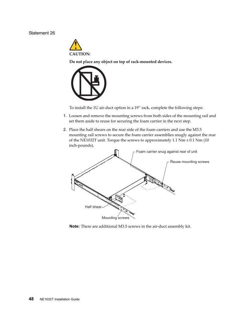
Statement 26
CAUTION:
Do not place any object on top of rack-mounted devices.
To install the 1U air-duct option in a 19” rack, complete the following steps:
1. Loosen and remove the mounting screws from both sides of the mounting rail and set them aside to reuse for securing the foam carrier in the next step.
2. Place the half shears on the rear side of the foam carriers and use the M3.5 mounting rail screws to secure the foam carrier assemblies snugly against the rear of the NE1032T unit. Torque the screws to approximately 1.1 Nm ± 0.1 Nm (10 inch-pounds).
Note: There are additional M3.5 screws in the air-duct assembly kit.
Half shear
Foam carrier snug against rear of unit
Reuse mounting screws
Mounting screws

© Copyright Lenovo 2018 Chapter 3: Installing NE1032T Hardware and Options 49
3. Secure the air-duct mounting bracket to the rails with M6 screws. Torque the screws to approximately 5.7 Nm ± 0.1 Nm (50 inch-pounds).
Note: Reuse the original M6 screws used to fasten the 4-post rack mounting brackets to secure the air duct mounting brackets with 4-post mounting brackets together.
4. Secure the air-duct mounting bracket to the rack chassis with M3.5 screws. Torque the screws to approximately 1.1 Nm ± 0.1 Nm (10 inch-pounds).
5. Plug the power cords into their respective NE1032T power connectors and using tie wraps, secure the power cords to the mounting rails.
M3.5 screws
Air duct mounting bracket
M6 screws
Tie wraps
Tie wraps
Power connection
Power connection

50 NE1032T Installation Guide
6. Gently slide the air-duct unit side flanges into the card guides until the unit is seated firmly. Make sure that the foam strip is oriented on top.
7. Secure the air-duct unit to the air-duct brackets with the two M4 thumbscrews.
M4thumbscrews
Side flangesCard guides
Foam

© Copyright Lenovo 2018 Chapter 3: Installing NE1032T Hardware and Options 51
Installing Port TransceiversThe NE1032T supports copper and optical transceivers.
To install a supported transceiver, see the following sections:
“Installing an SFP Copper Transceiver” on page 51
“Installing an SFP Optical Transceiver” on page 52
“Installing an SFP+ Optical Transceiver” on page 53
Installing an SFP Copper Transceiver
Approved 1 GbE SFP copper transceivers are supported in some breakout adapters that can be installed in SFP+ port slots. The SFP copper transceiver provides an RJ45 connector that accepts a standard 10/100/1000BASE-T (Category 5) cable.
Approved 1 GbE SFP copper transceivers are supported in G8296 SFP+ port slots. The SFP copper transceiver provides an RJ45 connector that accepts a standard 10/100/1000BASE-T (Category 5) cable in 100/1000T base T mode. When used in 10 GbE mode, you must use CAT6 copper cabling.
To install an SFP copper transceiver in an SFP+ port slot on the switch, complete the following steps.Note: To avoid damage to the cable or the SFP transceiver, do not connect the cable before you install the transceiver.
1. Remove the safety cap and pull the locking lever into the down (unlocked) position.
2. Insert the transceiver into the slot until it clicks into place. Use minimal pressure when you insert the transceiver. Do not use excessive force when you insert the transceiver or you might damage the transceiver or the slot.
Note: The transceiver has a mechanical guide key to prevent you from inserting the transceiver in an incorrect orientation.
3. Pull up the locking lever to lock the transceiver into place.
4. Connect the cable following the “Cabling Guidelines” on page 36.
To remove an SFP copper transceiver, disconnect the cable, and pull down the locking lever to release the transceiver. After you remove the transceiver, replace the safety cap.

52 NE1032T Installation Guide
Installing an SFP Optical Transceiver
Approved 1 GbE SFP optical transceivers are supported in NE1032T SFP+ port slots and in some breakout adapters that can be installed in SFP+ port slots. The SFP optical transceiver provides two fiber-optic cable connectors for connecting to external ports.
Statement 3
CAUTION:
When laser products (such as CD-ROMs, DVD drives, fiber optic devices, or transmitters) are installed, note the following:
Do not remove the covers. Removing the covers of the laser product could result in exposure to hazardous laser radiation. There are no serviceable parts inside the device.
Use of controls or adjustments or performance of procedures other than those specified herein might result in hazardous radiation exposure.
DANGER
Class 1 Laser Product
Laser Klasse 1
Laser Klass 1
Luokan 1 Laserlaite
Appareil À Laser de Classe 1
Some laser products contain an embedded Class 3A or Class 3B laser diode. Note the following.
Laser radiation when open. Do not stare into the beam, do not view directly with optical instruments, and avoid direct exposure to the beam.

© Copyright Lenovo 2018 Chapter 3: Installing NE1032T Hardware and Options 53
To install an SFP optical transceiver in an SFP+ port slot on the switch, complete the following steps.Note: To avoid damage to the cable or the SFP transceiver, do not connect the cable before you install the transceiver.
1. Remove the safety cap and pull the locking lever into the down (unlocked) position.
2. Insert the transceiver into the slot until it clicks into place. Use minimal pressure when you insert the transceiver. Do not use excessive force when you insert the transceiver or you might damage the transceiver or the slot.
Note: The transceiver has a mechanical guide key to prevent you from inserting the transceiver in an incorrect orientation.
3. Pull up the locking lever to lock the transceiver into place.
4. Connect the fiber-optic cable following the “Cabling Guidelines” on page 36.
To remove an SFP optical transceiver, disconnect the fiber-optic cable, and pull down the locking lever to release the transceiver. After you remove the transceiver, replace the safety cap.
Installing an SFP+ Optical Transceiver
Approved 10 GbE SFP+ optical transceivers are supported in NE1032T SFP+ port slots and in some breakout adapters that can be installed in SFP+ port slots. The SFP+ optical transceiver provides two fiber-optic cable connectors for connecting to external ports.
Statement 3
CAUTION:
When laser products (such as CD-ROMs, DVD drives, fiber optic devices, or transmitters) are installed, note the following:
Do not remove the covers. Removing the covers of the laser product could result in exposure to hazardous laser radiation. There are no serviceable parts inside the device.
Use of controls or adjustments or performance of procedures other than those specified herein might result in hazardous radiation exposure.
DANGER
Some laser products contain an embedded Class 3A or Class 3B laser diode. Note the following.
Laser radiation when open. Do not stare into the beam, do not view directly with optical instruments, and avoid direct exposure to the beam.

54 NE1032T Installation Guide
Class 1 Laser Product
Laser Klasse 1
Laser Klass 1
Luokan 1 Laserlaite
Appareil À Laser de Classe 1
To install an SFP+ optical transceiver in an SFP+ port slot on the switch, complete the following steps.Note: To avoid damage to the cable or the SFP+ transceiver, do not connect the cable before you install the transceiver.
1. Remove the safety cap and pull the locking lever into the down (unlocked) position.
2. Insert the transceiver into the slot until it clicks into place. Use minimal pressure when you insert the transceiver into the slot. Do not use excessive force when you insert the transceiver or you might damage the transceiver or the slot.
Note: The transceiver has a mechanical guide key to prevent you from inserting the transceiver in an incorrect orientation.
3. Pull up the locking lever to lock the transceiver into place.
4. Connect the fiber-optic cable following the “Cabling Guidelines” on page 36.
To remove an SFP+ optical transceiver, disconnect the fiber-optic cable, and pull down the locking lever to release the transceiver. After you remove the transceiver, replace the safety cap.

© Copyright Lenovo 2018 55
Chapter 4. Removing and Replacing Components
This chapter describes how to remove NE1032T hardware components for replacement. The following topics are covered:
“Removing Port Transceivers” on page 56
Removing and replacing hot-swap modules “Removing and Replacing a Power Supply Module” on page 57 “Removing and Replacing a Fan Module” on page 61
Removing the switch from one of the supported rack types “Removing the NE1032T from a Standard Equipment Rack” on page 63 “Removing the NE1032T from a Lenovo System x or Power Rack” on page 64
“Removing the Air-Duct Option” on page 68
“Replacing the NE1032T” on page 69

56 NE1032T Installation Guide
Removing Port Transceivers
Statement 3
CAUTION:
When laser products (such as CD-ROMs, DVD drives, fiber optic devices, or transmitters) are installed, note the following:
Do not remove the covers. Removing the covers of the laser product could result in exposure to hazardous laser radiation. There are no serviceable parts inside the device.
Use of controls or adjustments or performance of procedures other than those specified herein might result in hazardous radiation exposure.
DANGER
Class 1 Laser Product
Laser Klasse 1
Laser Klass 1
Luokan 1 Laserlaite
Appareil À Laser de Classe 1
To remove one of the installed SFP or SFP+ transceiver modules from the switch, complete the following steps:
1. Disconnect the port cable from the transceiver.
2. Pull down the locking lever to release the transceiver.
3. Gently slide the transceiver out of the switch.
4. After you remove the transceiver, replace the safety cap.
To replace the transceiver module, see the appropriate section under “Installing Port Transceivers” on page 51.
Some laser products contain an embedded Class 3A or Class 3B laser diode. Note the following.
Laser radiation when open. Do not stare into the beam, do not view directly with optical instruments, and avoid direct exposure to the beam.
© Copyright Lenovo 2018 Chapter 4: Removing and Replacing Components 57
Removing and Replacing a Power Supply ModuleThe rear panel of the NE1032T has two bays for hot-swap power supply modules. Two active power supply modules are required for load-sharing and redundancy. If one power supply module fails, you can replace it without powering off the switch or disrupting switch functions.
For proper airflow when operating the switch with only one power supply module, the empty power supply bay must be closed by a blank power filler plate.

58 NE1032T Installation Guide
Removing the Power Supply Module
Statement 5
CAUTION:
The power control button on the device and the power switch on the power supply do not turn off the electrical current supplied to the device. The device also might have more than one power cord. To remove all electrical current from the device, ensure that all power cords are disconnected from the power source.
To remove a hot-swap power supply module, complete the following steps:
1. Remove the power cord from the module’s power connector.
2. Press the release latch of the power supply module, and slide the module out of the bay.
Attention: Do not leave the power-supply bay empty for more than 90 seconds while the switch is operating. Either replace the power supply module or install a blank power filler plate.
To return the component to customer service for replacement, see Appendix A, “Getting Help and Technical Assistance“ to help you gather all the required information that is necessary to return a component. After you remove the component, securely pack the component for shipping.
1
2

© Copyright Lenovo 2018 Chapter 4: Removing and Replacing Components 59
Replacing the Power Supply Module
Statement 31
DANGER
Electrical current from power, telephone, and communication cables is hazardous.
To avoid a shock hazard:
Do not connect or disconnect any cables or perform installation, maintenance, or reconfiguration of this product during an electrical storm.
Connect all power cords to a properly wired and grounded power source.
Connect to properly wired power sources any equipment that will be attached to this product.
When possible, use one hand only to connect or disconnect signal cables.
Never turn on any equipment when there is evidence of fire, water, or structural damage.
Disconnect the attached ac power cords, dc power sources, network connections, telecommunications systems, and serial cables before you open the device covers, unless instructed otherwise in the installation and configuration procedures.
Connect and disconnect cables as described in the following table when you install, move, or open covers on this product or attached devices.

60 NE1032T Installation Guide
To replace a hot-swap power supply module, complete the following steps:
1. Select an empty power supply module bay on the rear of the switch. If the target bay is protected by a blank power filler plate, remove the blank.
2. Insert the power supply module into the selected power-supply bay and gently push it into the slot until it latches. Each power supply module has a mechanical guide key to prevent you from inserting the module incorrectly.
3. Connect the power cord to the power supply module and to an appropriate universal grounded AC power source.
4. Make sure that the power supply module’s LEDs are green.
To Connect:
1.Turn OFF all power sources and equipment that is to be attached to this product.
2.Attach signal cables to the product.
3.Attach power cords to the product.
For ac systems, use appliance inlets.
For dc systems, ensure correct polarity of -48 V dc connections: RTN is + and -48 V dc is -. Earth ground should use a two-hole lug for safety.
4.Attach signal cables to other devices.
5.Connect power cords to their sources.
6.Turn ON all the power sources.
To Disconnect:
1.Turn OFF all power sources and equipment that is to be attached to this product. For ac systems, remove all power
cords from the chassis power receptacles or interrupt power at the ac power distribution unit.
For dc systems, disconnect dc power sources at the breaker panel or by turning off the power source. Then, remove the dc cables.
2.Remove the signal cables from the connectors.
3.Remove all cables from the devices.

© Copyright Lenovo 2018 Chapter 4: Removing and Replacing Components 61
Removing and Replacing a Fan ModuleThe rear panel of the NE1032T has three bas for hot-swap fan modules. Three active fan modules are required for redundancy.
With active fan modules in all fan bays, if one fan fails, the switch will send an error message and continue operation. You can then replace the failed fan without powering off the switch or disrupting switch functions. If a second fan fails, the switch will send another error message, write a log message to flash memory, and shut down to prevent overheating.
Removing the Fan Module
CAUTION:Be sure to finish the replacement procedure promptly. The switch could overheat if left without cooling for an extended period.
To remove a hot-swap fan module, complete the following steps:
1. Loosen the retainer screw.
2. Grasp the extractor handle and gently pull the fan module from the slot.
Attention: If the inlet air temperature is above 35°C (95°F) while the switch is in operation, replace the fan module within five minutes to avoid overheating the switch.
To return the component to customer service for replacement, see Appendix A, “Getting Help and Technical Assistance“ to help you gather all the required information that is necessary to return a component. After you remove the component, securely pack the component for shipping.
Retainer Screw

62 NE1032T Installation Guide
Replacing the Fan Module
To replace a hot-swap fan module, complete the following steps:
1. Select an empty fan module bay on the rear of the switch. If the target bay is covered by a blank fan filler plate, loosen the retainer screw and slide the filler plate out of the slot.
2. Remove the new fan module from the antistatic shielded bag.
3. Slide the fan module into the card guides in the open slot and gently push it all the way into the slot, so that it firmly engages with the connector (see the illustration). Each fan module has a mechanical guide key to prevent you from inserting the module incorrectly.
4. Tighten the retaining screw on the fan module. Torque the screw to approximately 0.25 Nm +/- 0.1 Nm (2 inch-pounds).
5. Make sure that the fan module’s LED is lit.
Retainer Screw

© Copyright Lenovo 2018 Chapter 4: Removing and Replacing Components 63
Removing the NE1032T from a Standard Equipment RackThis section describes how to remove the NE1032T from a standard 19-inch equipment rack. For information about removing the switch from other supported racks, see the appropriate section in this chapter.
To remove the NE1032T from a standard rack, complete the following steps:
1. Disconnect all external cables.
2. If the air-duct option has been installed, remove it as described in “Removing the Air-Duct Option” on page 68.
3. Loosen and remove M6 screws, washers, and clip nuts (or cage nuts) to release the switch unit from the rack.
4. Slide the switch unit out of the rack.
5. Loosen and remove the M4 screws attaching the mounting bracket on each side of the switch.
6. If replacing the unit with another NE1032T, see “Replacing the NE1032T” on page 69.
63
4
21

64 NE1032T Installation Guide
Removing the NE1032T from a Lenovo System x or Power Rack
This section describes how to remove the NE1032T from a Lenovo System x or Power 4-post rack.
To remove the NE1032T from a System x or Power rack, complete the following steps:
1. Disconnect all external cables.
2. If the air-duct option has been installed, remove it as described in “Removing the Air-Duct Option” on page 68.
3. Loosen and remove M3.5 screws that secure the rear brackets to the front brackets.
4. Loosen and remove the M6 screws, washers, and clip nuts (or cage nuts) that attach the filler plate and rear mounting brackets to the rear rack posts.
5. Slide the rear mounting brackets out of their slots in the front mounting brackets.
3
10
59
8
7

© Copyright Lenovo 2018 Chapter 4: Removing and Replacing Components 65
6. Loosen and remove the M6 screws, washers, and clip nuts (or cage nuts) connecting the front mounting brackets to the front rack posts.
7. Slide the NE1032T unit out of the rack.
8. Loosen and remove the M4 screws that attach the front mounting brackets to each side of the switch.
9. If replacing the unit with another NE1032T, see “Replacing the NE1032T” on page 69.
5
10
3
2
61
1

66 NE1032T Installation Guide
Removing the NE1032T from a Lenovo iDataPlex RackThis section describes how to remove the NE1032T from a Lenovo iDataPlex rack.
To remove the NE1032T from an iDataPlex rack, complete the following steps:
1. Disconnect all external cables.
2. If the 1U air-duct option has been installed, remove it as described in “Removing the Air-Duct Option” on page 68.
3. Loosen and remove the M6 washers, screws, and clip nuts that attach the alignment plate.
4. Loosen and remove the M6 washers and screws that mount the switch into the rack.
7
3
5
4
5
3
4

© Copyright Lenovo 2018 Chapter 4: Removing and Replacing Components 67
5. Slide the switch out of the rack.
6. Loosen and remove the M4 screws that attach front and rear mounting brackets to each side of the switch.
7. If replacing the unit with another NE1032T, see “Replacing the NE1032T” on page 69.
1 2
6

68 NE1032T Installation Guide
Removing the Air-Duct OptionThe NE1032T supports an optional 1U air duct to maximize air flow conditions in a Lenovo Power Systems Group rack.
To remove an installed 1U air-duct option from a 19” rack, complete the following steps.
1. Loosen the M4 thumbscrews securing the air-duct unit to the mounting brackets.
2. Slide the 1U air-duct unit out of the rack.
To return the component to customer service for replacement, see Appendix A, “Getting Help and Technical Assistance“ to help you gather all the required information. After you remove the component, securely pack it for shipping.
For instructions to install a replacement air-duct option, see “Installing the Air-Duct Option” on page 47.
M4thumbscrews

© Copyright Lenovo 2018 Chapter 4: Removing and Replacing Components 69
Replacing the NE1032T
Preparing and Returning the NE1032T
If replacing the NE1032T, remove all associated components and options according to the instructions in this chapter. Remove and retain clips, cords, cables, modules, caps or blanks, air-duct option (if installed), and any mounting hardware. These items can then be reinstalled on the replacement unit.
When you remove the NE1032T from the rack, record the product Machine Type-Model (MTM) number and serial number to use for the replacement switch. See “Before Installing the NE1032T” on page 32 to locate the product information labels on the switch or through the switch firmware interface.
To return the chassis to customer service for replacement, see Appendix A, “Getting Help and Technical Assistance“ to help you gather all the required information that is necessary to return a component. After you remove the NE1032T unit, securely pack it for shipping.
Replace power and fan modules. For details, see “Removing and Replacing a Power Supply Module” on page 57 and “Removing and Replacing a Fan Module” on page 61.
Install the replacement NE1032T hardware as directed in Chapter 3, “Installing NE1032T Hardware and Options“). Once the hardware is installed, configure the Vital Product Data (VPD) on the replacement switch as shown in the following section.
Configuring Vital Product Data
After you install the replacement NE1032T hardware (the new unit), you must configure the new unit to use the VPD of the unit which was removed (the old unit), in order to avoid losing any licensed electronic entitlement data. The required information consists of the old unit’s MTM and serial number, which was collected from the old unit according to “Before Installing the NE1032T” on page 32.
To configure the VPD on a new switch, complete the following steps.
1. Log in to the new NE1032T as directed in Chapter 5, “Initializing the NE1032T“. At the login prompt, the default username is admin and the default password is admin.
2. Use the following CLI commands to enter the Executive configuration mode:
NE1032T> enableNE1032T# configure [device]NE1032T(config)#

70 NE1032T Installation Guide
3. Set the new switch to use the Machine Type-Model (MTM) number of the old unit. For example:
where 1234-56X is the MTM from your old unit.Note: The MTM shown here is merely an example. Use the actual MTM recorded from your old NE1032T unit.
4. Set the new switch to use the serial number of the old unit. For example:
where XX01234567 is the serial number of your old unit.Note: The serial number shown here is merely an example. Use the actual serial number recorded from your old NE1032T unit.
5. Reset the switch using the following command:
6. When prompted for confirmation, enter y. The switch will then restart.
7. After the switch reboots, return to the command prompt and verify that the VPD information is correct using the following command:
For more information about using the switch interface, see the Application Guide and Command Reference for the NE1032T and its corresponding Lenovo Network Operating System and firmware version.
NE1032T(config)# hardware mtm 1234-56XNew MTM value: 1234-56XPlease reset the system for the new changes to take effect
NE1032T(config)# hardware esn XX01234567
NE1032T# reload
NE1032T> display sys-info
*** display boot ***Current ZTP State: EnableCurrent FLASH software: active image: version 10.4.2.0 standby image: version 10.4.2.0 Uboot: version 10.4.2.0Currently set to boot software active imageCurrent port mode: default
Currently scheduled reboot time: none
...System Name: NE1032TSystem Description: NE1032TSystem Model: LENOVO NE1032TSystem Manufacture Date: 1304System Serial Number: XX01234567...

© Copyright Lenovo 2018 71
Chapter 5. Initializing the NE1032T
When you supply power to the NE1032T, the switch initializes automatically for basic functions.
Statement 5
CAUTION:
The power control button on the device and the power switch on the power supply do not turn off the electrical current supplied to the device. The device also might have more than one power cord. To remove all electrical current from the device, ensure that all power cords are disconnected from the power source.
1
2

72 NE1032T Installation Guide
System Status LEDsThe following LEDs on the switch front panel indicate the overall system status:
Power - Steady green if the both power cords are connected, or flashing green if the only one power cord is connected.
Service - Off if the system is OK, or flashing if service is required.
For additional LED indicators, see the appropriate section in Chapter 2, “Switch Components“.

© Copyright Lenovo 2018 Chapter 5: Initializing the NE1032T 73
Connecting to the SwitchUse the switch Command-Line Interface (CLI) to perform additional configuration tasks. You can access the CLI using the serial console port or management port.
Using the Serial Console Port
You can access the switch CLI through the serial console port on the front panel of the switch. This port uses RS-232 serial communications. Use the console cable kit to connect the serial console port to a terminal or a computer running a terminal emulation program.
The console port terminal-emulation requirements are as follows:
Default baud rate = 9,600 bps
Character size = 8 characters
Parity = none
Stop bits = 1
Data bits = 8
Flow control = none
Using the Management Port
If the switch is connected to a network that employs DHCP, you can also access the switch CLI through the RJ45 management port. This port uses Ethernet communications and can be accessed using Telnet or SNMP via the IP address provided by the network’s DHCP server.

74 NE1032T Installation Guide
Logging Into the SwitchWhen the switch starts, it performs initial self tests, and then prompts for the login. For example:
At the prompt, type the switch username and password and press Enter. The default username is admin and the default password is admin.Note: If the switch has already started prior to your connection, you may need to press Enter to display the password prompt.
After successfully logging into the switch, the following CLI prompt will be displayed:
********* Booting Lenovo CNOS image 1 *********4019996 bytes read in 338 ms (11.3 MiB/s)30611 bytes read in 139 ms (214.8 KiB/s)********* Booting active image 1 *********Booting OS Starting udevINIT: version 2.88 bootingINIT: version 2.88 bootingmknod /dev/blade-irq c 249 0 - OK
…
Poky (Yocto Project Reference Distro) 2.1.2 NE1032T /dev/ttyS0
NE1032T login:
NOS version 10.4.2.0 LENOVO NE1032T, Thu Feb 9 16:09:11 PST 2017
NE1032T>

© Copyright Lenovo 2018 Chapter 5: Initializing the NE1032T 75
Default Configuration FilesThe switch firmware contains default configuration files that are loaded at the factory. When the switch first initializes, the default configuration files are loaded into the active switch memory. The default settings allow the switch to perform basic functions with minimal effort by the system administrator.
Custom configuration settings made by the administrator will override the default settings and can be saved so that they are retained if the switch is rebooted. However, if desired, you can revert the custom configuration settings to the original factory defaults. The original factory default configuration files are a permanent part of the firmware; you cannot deleted them or change their original definitions.
To reset the switch to its factory defaults, you can use one of the following methods:
Use the CLI to reset the switch to factory defaults:Erase the switch startup configuration:
Enter y at the prompt to confirm the erasing process and then reload the switch:
Using the Management Boot Menu by selecting Change configuration to factory default. For more details, see “The Boot Management Menu” on page 79.
NE1032T> enableNE1032T# save erase
Warning: This command will erase the startup-configuration.Do you wish to proceed anyway? (y/n) [n] y
NE1032T# reload

76 NE1032T Installation Guide
Configuring the Management Interface for Remote AccessTo manage the switch remotely using Telnet or SNMP you must first configure the management interface. You can use DHCP to automatically configure the interface (enabled by default), or you can manually configure the following IP parameters:
IP address and subnet mask
Gateway address
By default, DHCP is enabled on the management interface. If there is no DHCP offer received, the switch uses the default management IP address (192.168.50.50/24). This address is overwritten when a DHCP address is received for that interface. If DHCP is enabled and there is no static address configured for DHCP, requests will continue to be sent. This feature does not change existing DHCP functionality.
To configure the management interface for remote management, you can choose between following two options:
configure an out-of-band management IP address and a default gateway
configure an in-band management IP address over a Switch Virtual Interface (SVI) interface and an associated default gateway
After you configure the IP address for your switch and you have an existing network connection, you can use the Telnet program from an external management station to access and control the switch. The management station and your switch must be on the same IP subnet.
The switch CLI allows you to configure and control the switch over the network using the Telnet program. You can use the CLI to perform many basic network management functions. In addition, you can configure the switch for management using an SNMP-based network management system.
For more information about using the CLI, see the Command Reference guide for your specific switch and firmware version.

© Copyright Lenovo 2018 Chapter 5: Initializing the NE1032T 77
Out-of-Band Management Interface Configuration
Complete the following steps to configure an out-of-band management IP address and a default gateway:
1. Log onto the switch using the serial console port or management port on the NE1032T front panel.
2. Enter the management interface configuration mode:
3. Configure an IP address and subnet mask:
4. Configure the out-of-band default gateway:
In-Band Management Interface Configuration
Complete the following steps to configure an in-band management IP address over an SVI interface and an associated default gateway:
1. Log onto the switch using the serial console port or management port on the NE1032T front panel.
2. Enter the SVI interface configuration mode:
3. Configure the in-band management IP address:
4. Configure the in-band default gateway:
NE1032T> enableNE1032T# configure deviceNE1032T(config)# interface mgmt 0NE1032T(config-if)#
NE1032T(config-if)# ip address 10.254.87.6/24NE1032T(config-if)# exitNE1032T(config)#
NE1032T(config)# vrf context managementNE1032T(config-vrf)# ip route 0.0.0.0/0 205.21.17.1NE1032T(config-vrf)# exitNE1032T(config)#
NE1032T> enableNE1032T# configure [device]NE1032T(config)#
NE1032T(config)# interface vlan 1NE1032T(config-if)# ip address 10.254.87.6/24NE1032T(config-if)# exitNE1032T(config)#
NE1032T(config)# ip route 0.0.0.0/0 205.21.17.1

78 NE1032T Installation Guide
Updating FirmwareIf firmware updates are available, you can download them from the Lenovo website. The switch might have features that are not described in the documentation that comes with the switch, and the documentation might be updated occasionally to include information about those features, or technical updates might be available to provide additional information that is not included in the switch documentation.
Configuration settings are lost during a firmware update. Before updating the firmware, save a copy of the configuration to a separate device. In the event of a failed update, the saved configuration can be restored. For more information about the configuration file, see the Command Reference guide for your specific switch and firmware version.
Attention: Installing the wrong firmware update might cause the network switch to malfunction. Before you install a firmware, read any release notes, readme files and change history files that are provided with the downloaded update. These files contain important information about the update and the procedure for installing the update, including any special procedure for updating from an early firmware version to the latest version.
To check for firmware and documentation updates, go to the Lenovo website:http://support.lenovo.com/
Note: Changes are made periodically to the Lenovo website. Procedures for locating firmware and documentation might vary slightly from what is described in this document.

© Copyright Lenovo 2018 Chapter 5: Initializing the NE1032T 79
The Boot Management MenuThe Boot Management menu allows you to switch the NOS image, reset the default user password, or to recover from a failed software installation.
You can interrupt the startup process and enter the Boot Management menu from the serial console port. When the system displays the following message, pressShift + B. The Boot Management menu will appear.
The Boot Management menu allows you to perform the following actions:
To change the booting image, press I and follow the screen prompts.
To reset the switch configuration to factory defaults, press C and follow the screen prompts.
To boot in recovery mode, press R.
To reset the Network Administrator account (admin) password, press P and follow the screen prompts.
To reset the password required to enter Privileged EXEC configuration mode, press B and follow the screen prompts.
To reload the switch, press Q. The reloading process will start again.
To exit the Boot Management menu, press E. The reloading process continues.
The system is going down for reboot NOW!INIT: reboot: Restarting system
...
Press shift-B for startup menu or shift-R for recovery mode: ..Running Startup Menu
...
Boot Management Menu I - Change booting image C - Change configuration to factory default R - Boot in recovery mode (tftp and xmodem download of images to recover switch) P - Reset the Network Administrator (admin) password B - Reset the password required to enter privileged exec mode Q - Reboot E - ExitPlease choose your menu option:
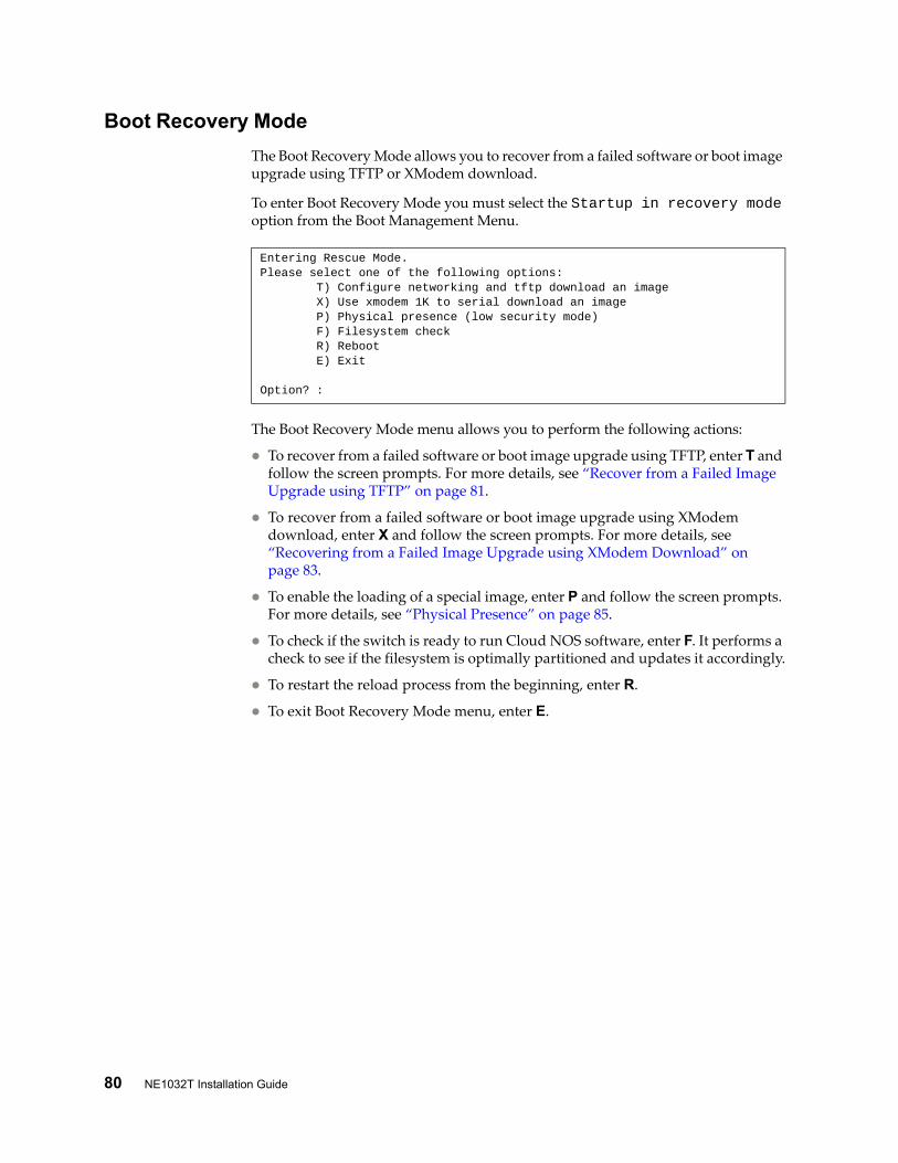
80 NE1032T Installation Guide
Boot Recovery Mode
The Boot Recovery Mode allows you to recover from a failed software or boot image upgrade using TFTP or XModem download.
To enter Boot Recovery Mode you must select the Startup in recovery mode option from the Boot Management Menu.
The Boot Recovery Mode menu allows you to perform the following actions:
To recover from a failed software or boot image upgrade using TFTP, enter T and follow the screen prompts. For more details, see “Recover from a Failed Image Upgrade using TFTP” on page 81.
To recover from a failed software or boot image upgrade using XModem download, enter X and follow the screen prompts. For more details, see “Recovering from a Failed Image Upgrade using XModem Download” on page 83.
To enable the loading of a special image, enter P and follow the screen prompts. For more details, see “Physical Presence” on page 85.
To check if the switch is ready to run Cloud NOS software, enter F. It performs a check to see if the filesystem is optimally partitioned and updates it accordingly.
To restart the reload process from the beginning, enter R.
To exit Boot Recovery Mode menu, enter E.
Entering Rescue Mode.Please select one of the following options: T) Configure networking and tftp download an image X) Use xmodem 1K to serial download an image P) Physical presence (low security mode) F) Filesystem check R) Reboot E) Exit
Option? :

© Copyright Lenovo 2018 Chapter 5: Initializing the NE1032T 81
Recover from a Failed Image Upgrade using TFTP
Use the following procedure to recover from a failed image upgrade using TFTP:
1. Connect a PC to the console port of the switch.
2. Open a terminal emulator program that supports the Telnet protocol (for example, HyperTerminal, SecureCRT, or PuTTY) and input the proper hostname or IP address and the port to connect to the console interface of the switch.
3. Reload the switch and access the Boot Management menu by pressing Shift + B when the following message appears and the dots are being displayed.
4. Enter Boot Recovery Mode by selecting R. The Recovery Mode menu will appear.
5. To start the recovery process using TFTP, select T. The following message will appear:
6. Enter the IP address of the management port:
7. Enter the network mask of the management port:
8. Enter the gateway of the management port:
9. Enter the IP address of the TFTP server:
10. Enter the file path and the filename of the image:
After the procedure is complete, the Recovery Mode menu will be redisplayed.
Press shift-B for startup menu or shift-R for recovery mode: ...
Performing TFTP rescue. Please answer the following questions (enter 'q' to quit):
IP addr :
Netmask :
Gateway :
Server addr:
Image Filename:

82 NE1032T Installation Guide
Following is an example of a successful recovery procedure using TFTP:
Entering Rescue Mode.Please select one of the following options: T) Configure networking and tftp download an image X) Use xmodem 1K to serial download an image P) Physical presence (low security mode) F) Filesystem check R) Reboot E) Exit
Option? : tPerforming TFTP rescue. Please answer the following questions (enter 'q' to quit):IP addr :10.241.6.4Netmask :255.255.255.128Gateway :10.241.6.66Server addr:10.72.97.135Image Filename: NE1032T-CNOS-10.4.2.0.imgs Netmask : 255.255.255.128 Gateway : 10.241.6.66Configuring management port.......................Installing image NE1032T-CNOS-10.4.2.0.imgs from TFTP server 10.72.97.135
Extracting images ... Do *NOT* power cycle the switch.Installing Application: Image signature verified.Installing image as standby image: 100%
Standby image update succeededUpdating install log. File NE1032T-CNOS-10.4.2.0.imgs installed from 10.72.97.135 at 15:29:30 on 12-3-2015Please select one of the following options: T) Configure networking and tftp download an image X) Use xmodem 1K to serial download an image P) Physical presence (low security mode) F) Filesystem check R) Reboot E) Exit
Option? :

© Copyright Lenovo 2018 Chapter 5: Initializing the NE1032T 83
Recovering from a Failed Image Upgrade using XModem Download
Use the following procedure to recover from a failed image upgrade.
1. Connect a PC to the serial port of the switch.
2. Open a terminal emulator program that supports Xmodem download (for example, HyperTerminal, SecureCRT or PuTTY) and select the following serial port characteristics:
Speed: 9,600 bps
Data Bits: 8
Stop Bits: 1
Parity: None
Flow Control: None
3. Reload the switch and access the Boot Management menu by pressing Shift + B when the following message appears and the dots are being displayed.
4. Enter Boot Recovery Mode by selecting R. The Recovery Mode menu will appear.
5. Select X for Xmodem download. You will see the following display:
6. When you see the following message, change the Serial Port speed to 115,200 bps:
7. Press Enter to set the system into download accept mode. When the readiness meter displays (a series of “C” characters), start Xmodem on your terminal emulator. You will see a display similar to the following:
8. Select the image to download. Xmodem initiates the file transfer. When download is complete, you are asked to change the Serial Port speed back to 9,600 bps:
Press shift-B for startup menu or shift-R for recovery mode: ...
Running xmodem rescue.....
Change the baud rate to 115200 bps and hit the <ENTER> key before initiating the download.
... Waiting for the <Enter> key to be hit before the download can start...CC
Change the baud rate back to 9600 bps, hit the <ENTER> key

84 NE1032T Installation Guide
9. Press Enter to start installing the image.
The image install will begin. After the procedure is complete, the Recovery Mode menu will be redisplayed.
Boot image recovery is complete.
Extracting images ... Do *NOT* power cycle the switch.Installing Root Filesystem:Image signature verified. 100%Installing Kernel:Image signature verified. 100%Installing Device Tree:Image signature verified. 100%Installing Boot Loader: 100%Updating install log. File image installed from xmodem at 18:06:02 on 13-3-2015Please select one of the following options: T) Configure networking and tftp download an image X) Use xmodem 1K to serial download an image P) Physical presence (low security mode) F) Filesystem check R) Reboot E) Exit
Option? :

© Copyright Lenovo 2018 Chapter 5: Initializing the NE1032T 85
Physical Presence
Use the following procedure to enable the installation of special images on the switch, when a deeper troubleshooting analysis is required:
1. Connect a PC to the console port of the switch.
2. Open a terminal emulator program that supports a serial port connection and select the following serial port characteristics:
Speed: 9,600 bps
Data Bits: 8
Stop Bits: 1
Parity: None
Flow Control: None
3. Boot the switch and access the Boot Management menu by pressing Shift + B when the following message appears and the dots are being displayed.
4. Enter Boot Recovery Mode by selecting R. The Recovery Mode menu will appear.
5. To begin the Physical Presence procedure, select P. The following warning message will appear and you will be prompted for confirmation (enter y to confirm):
6. A security test will be performed. The system location (blue) LED will blink a number of times between 1 and 12. Enter that number:
7. After entering the correct number, the Recovery Mode menu will reappear. To install a special image, use one of the following procedures:
TFTP (for details, see page 81)
XModem Download (for details, see page 83)Note: You have three attempts to successfully complete the security test. After three incorrect attempts, the switch will reboot.
After the test is completed, the switch will be put in low security mode. This mode will allow you to install special images on the switch. To revert to normal security mode, you must reboot the switch or enter P again in the Recovery Mode menu.
Press shift-B for startup menu or shift-R for recovery mode: ...
WARNING: the following test is used to determine physical presence and if completed will put the switch in low security mode.
Do you wish to continue y/n? y
Hit a key to start the test. The blue location LED will blink a number of times.
...........How many times did the LED blink?

86 NE1032T Installation Guide

© Copyright Lenovo 2018 87
Chapter 6. Troubleshooting
This section contains basic troubleshooting information to help resolve problems that might occur during installation and operation of the switch. If you have problems accessing the switch or working with the firmware, see the NE1032T Application Guide and/or the Command Reference.
For information about calling Lenovo for service, see Appendix A, “Getting Help and Technical Assistance“.

88 NE1032T Installation Guide
System LED Is Not LitSymptom: The power supply LED is not lit.
Solution: Check the power supply to make sure that there is a proper connection to the power source. Make sure that power is available from the power source.

© Copyright Lenovo 2018 Chapter 6: Troubleshooting 89
Port Link LED Is Not LitSymptom: The port link LED is not lit.
Solution 1: Check the port configuration in the firmware (see the Command Reference). If the port is configured with a specific speed or duplex mode, check the other device to make sure that it is set to the same configuration. If the switch port is set to auto-negotiate, make sure that the other device is set to auto-negotiate.
Solution 2: Check the cables that connect the port to the other device. Make sure that they are connected correctly. Make sure that you are using the correct cable type.

90 NE1032T Installation Guide
Temperature Sensor WarningSymptom: A temperature warning is displayed on the management console.
Solution: Make sure that the air circulation vents on the front, back, and sides of the switch are free from obstruction by cables, panels, rack frames, or other materials.
Make sure that all cooling fans inside the switch are running. A fan module LED (rear panel) flashes if there is a failure of the fan. The following CLI command displays fan status:
Lenovo Cloud Network Operating System (CNOS):
If any fan stops during switch operation, contact Customer Support.
NE1032T> display sys-info
© Copyright Lenovo 2018 Chapter 6: Troubleshooting 91
Switch Does Not Initialize (Boot)Symptom: All the switch LEDs stay on, and the command prompt is not displayed on the console.
Solution: The operating system might be damaged. Use the console port to perform a serial upgrade of the switch firmware. See the Command Reference.

92 NE1032T Installation Guide
© Copyright Lenovo 2018 93
Appendix A. Getting Help and Technical Assistance
If you need help, service, or technical assistance or just want more information about Lenovo products, you will find a wide variety of sources available from Lenovo to assist you.
Use this information to obtain additional information about Lenovo and Lenovo products, and determine what to do if you experience a problem with your Lenovo system or optional device.Note: This section includes references to IBM web sites and information about obtaining service. IBM is Lenovo's preferred service provider for the System x, Flex System, and NeXtScale System products.
Before you call, make sure that you have taken these steps to try to solve the problem yourself.
If you believe that you require warranty service for your Lenovo product, the service technicians will be able to assist you more efficiently if you prepare before you call.
Check all cables to make sure that they are connected.
Check the power switches to make sure that the system and any optional devices are turned on.
Check for updated software, firmware, and operating-system device drivers for your Lenovo product. The Lenovo Warranty terms and conditions state that you, the owner of the Lenovo product, are responsible for maintaining and updating all software and firmware for the product (unless it is covered by an additional maintenance contract). Your service technician will request that you upgrade your software and firmware if the problem has a documented solution within a software upgrade.
If you have installed new hardware or software in your environment, check the Lenovo Support portal to make sure that the hardware and software is supported by your product., and where you can check for information to help you solve the problem.
Gather the following information to provide to the service technician. This data will help the service technician quickly provide a solution to your problem and ensure that you receive the level of service for which you might have contracted. Hardware and Software Maintenance agreement contract numbers, if
applicable Machine type number (if applicable–Lenovo 4-digit machine identifier) Model number Serial number Current system UEFI and firmware levels Other pertinent information such as error messages and logs
Start the process of determining a solution to your problem by making the pertinent information available to the service technicians. The IBM service technicians can start working on your solution as soon as you have completed and submitted an Electronic Service Request.

94 NE1032T Installation Guide
You can solve many problems without outside assistance by following the troubleshooting procedures that Lenovo provides in the online help or in the Lenovo product documentation. The Lenovo product documentation also describes the diagnostic tests that you can perform. The documentation for most systems, operating systems, and programs contains troubleshooting procedures and explanations of error messages and error codes. If you suspect a software problem, see the documentation for the operating system or program.

© Copyright Lenovo 2018 95
Appendix B. Notices
Lenovo may not offer the products, services, or features discussed in this document in all countries. Consult your local Lenovo representative for information on the products and services currently available in your area.
Any reference to a Lenovo product, program, or service is not intended to state or imply that only that Lenovo product, program, or service may be used. Any functionally equivalent product, program, or service that does not infringe any Lenovo intellectual property right may be used instead. However, it is the user's responsibility to evaluate and verify the operation of any other product, program, or service.
Lenovo may have patents or pending patent applications covering subject matter described in this document. The furnishing of this document does not give you any license to these patents. You can send license inquiries, in writing, to:
Lenovo (United States), Inc.1009 Think Place - Building OneMorrisville, NC 27560U.S.A.Attention: Lenovo Director of Licensing
LENOVO PROVIDES THIS PUBLICATION “AS IS” WITHOUT WARRANTY OF ANY KIND, EITHER EXPRESS OR IMPLIED, INCLUDING, BUT NOT LIMITED TO, THE IMPLIED WARRANTIES OF NON-INFRINGEMENT, MERCHANTABILITY OR FITNESS FOR A PARTICULAR PURPOSE. Some jurisdictions do not allow disclaimer of express or implied warranties in certain transactions, therefore, this statement may not apply to you.
This information could include technical inaccuracies or typographical errors. Changes are periodically made to the information herein; these changes will be incorporated in new editions of the publication. Lenovo may make improvements and/or changes in the product(s) and/or the program(s) described in this publication at any time without notice.
The products described in this document are not intended for use in implantation or other life support applications where malfunction may result in injury or death to persons. The information contained in this document does not affect or change Lenovo product specifications or warranties.
Nothing in this document shall operate as an express or implied license or indemnity under the intellectual property rights of Lenovo or third parties. All information contained in this document was obtained in specific environments and is presented as an illustration. The result obtained in other operating environments may vary.
Lenovo may use or distribute any of the information you supply in any way it believes appropriate without incurring any obligation to you.
Any references in this publication to non-Lenovo Web sites are provided for convenience only and do not in any manner serve as an endorsement of those Web sites. The materials at those Web sites are not part of the materials for this Lenovo product, and use of those Web sites is at your own risk.

96 NE1032T Installation Guide
Any performance data contained herein was determined in a controlled environment. Therefore, the result obtained in other operating environments may vary significantly. Some measurements may have been made on development-level systems and there is no guarantee that these measurements will be the same on generally available systems. Furthermore, some measurements may have been estimated through extrapolation. Actual results may vary. Users of this document should verify the applicable data for their specific environment.

© Copyright Lenovo 2018 Appendix B: Notices 97
TrademarksLenovo, the Lenovo logo, Flex System, System x, NeXtScale System, and X-Architecture are trademarks of Lenovo in the United States, other countries, or both.
Intel and Intel Xeon are trademarks of Intel Corporation in the United States, other countries, or both.
Internet Explorer, Microsoft, and Windows are trademarks of the Microsoft group of companies.
Linux is a registered trademark of Linus Torvalds.
Other company, product, or service names may be trademarks or service marks of others.

98 NE1032T Installation Guide
Important NotesProcessor speed indicates the internal clock speed of the microprocessor; other factors also affect application performance.
CD or DVD drive speed is the variable read rate. Actual speeds vary and are often less than the possible maximum.
When referring to processor storage, real and virtual storage, or channel volume, KB stands for 1,024 bytes, MB stands for 1,048,576 bytes and GB stands for 1,073,741,824 bytes.
When referring to hard disk drive capacity or communications volume, MB stands for 1,000,000 bytes and GB stands for 1,000,000,000 bytes. Total user-accessible capacity can vary depending on operating environments.
Maximum internal hard disk drive capacities assume the replacement of any standard hard disk drives and population of all hard-disk-drive bays with the largest currently supported drives that are available from Lenovo.
Maximum memory might require replacement of the standard memory with an optional memory module.
Each solid-state memory cell has an intrinsic, finite number of write cycles that the cell can incur. Therefore, a solid-state device has a maximum number of write cycles that it can be subjected to, expressed as total bytes written (TBW). A device that has exceeded this limit might fail to respond to system-generated commands or might be incapable of being written to. Lenovo is not responsible for replacement of a device that has exceeded its maximum guaranteed number of program/erase cycles, as documented in the Official Published Specifications for the device.
Lenovo makes no representations or warranties with respect to non-Lenovo products. Support (if any) for the non-Lenovo products is provided by the third party, not Lenovo.
Some software might differ from its retail version (if available) and might not include user manuals or all program functionality.

© Copyright Lenovo 2018 Appendix B: Notices 99
Recycling InformationLenovo encourages owners of information technology (IT) equipment to responsibly recycle their equipment when it is no longer needed. Lenovo offers a variety of programs and services to assist equipment owners in recycling their IT products. For information on recycling Lenovo products, go to:
http://www.lenovo.com/recycling

100 NE1032T Installation Guide
Particulate ContaminationAttention: Airborne particulates (including metal flakes or particles) and reactive gases acting alone or in combination with other environmental factors such as humidity or temperature might pose a risk to the device that is described in this document.
Risks that are posed by the presence of excessive particulate levels or concentrations of harmful gases include damage that might cause the device to malfunction or cease functioning altogether. This specification sets forth limits for particulates and gases that are intended to avoid such damage. The limits must not be viewed or used as definitive limits, because numerous other factors, such as temperature or moisture content of the air, can influence the impact of particulates or environmental corrosives and gaseous contaminant transfer. In the absence of specific limits that are set forth in this document, you must implement practices that maintain particulate and gas levels that are consistent with the protection of human health and safety. If Lenovo determines that the levels of particulates or gases in your environment have caused damage to the device, Lenovo may condition provision of repair or replacement of devices or parts on implementation of appropriate remedial measures to mitigate such environmental contamination. Implementation of such remedial measures is a customer responsibility..
Contaminant Limits
Particulate • The room air must be continuously filtered with 40% atmospheric dust spot efficiency (MERV 9) according to ASHRAE Standard 52.21.
• Air that enters a data center must be filtered to 99.97% efficiency or greater, using high-efficiency particulate air (HEPA) filters that meet MIL-STD-282.
• The deliquescent relative humidity of the particulate contamination must be more than 60%2.
• The room must be free of conductive contamination such as zinc whis-kers.
Gaseous • Copper: Class G1 as per ANSI/ISA 71.04-19853
• Silver: Corrosion rate of less than 300 Å in 30 days
1 ASHRAE 52.2-2008 - Method of Testing General Ventilation Air-Cleaning Devices for Removal Efficiency by Particle Size. Atlanta: American Society of Heating, Refrigerating and Air-Con-ditioning Engineers, Inc.2 The deliquescent relative humidity of particulate contamination is the relative humidity at which the dust absorbs enough water to become wet and promote ionic conduction.3 ANSI/ISA-71.04-1985. Environmental conditions for process measurement and control systems: Airborne contaminants. Instrument Society of America, Research Triangle Park, North Car-olina, U.S.A.

© Copyright Lenovo 2018 Appendix B: Notices 101
Telecommunication Regulatory StatementThis product may not be certified in your country for connection by any means whatsoever to interfaces of public telecommunications networks. Further certification may be required by law prior to making any such connection. Contact a Lenovo representative or reseller for any questions.

102 NE1032T Installation Guide
Electronic Emission NoticesWhen you attach a monitor to the equipment, you must use the designated monitor cable and any interference suppression devices that are supplied with the monitor.
Federal Communications Commission (FCC) Statement
Note: This equipment has been tested and found to comply with the limits for a Class A digital device, pursuant to Part 15 of the FCC Rules. These limits are designed to provide reasonable protection against harmful interference when the equipment is operated in a commercial environment. This equipment generates, uses, and can radiate radio frequency energy and, if not installed and used in accordance with the instruction manual, may cause harmful interference to radio communications. Operation of this equipment in a residential area is likely to cause harmful interference, in which case the user will be required to correct the interference at his own expense.
Properly shielded and grounded cables and connectors must be used to meet FCC emission limits. Lenovo is not responsible for any radio or television interference caused by using other than recommended cables and connectors or by unauthorized changes or modifications to this equipment. Unauthorized changes or modifications could void the user’s authority to operate the equipment.
This device complies with Part 15 of the FCC Rules. Operation is subject to the following two conditions: (1) this device may not cause harmful interference, and (2) this device must accept any interference received, including interference that might cause undesired operation.
Industry Canada Class A Emission Compliance Statement
This Class A digital apparatus complies with Canadian ICES-003.
Avis de Conformité à la Réglementation d'Industrie Canada
Cet appareil numérique de la classe A est conforme à la norme NMB-003 du Canada.
Australia and New Zealand Class A Statement
Attention: This is a Class A product. In a domestic environment this product may cause radio interference in which case the user may be required to take adequate measures.

© Copyright Lenovo 2018 Appendix B: Notices 103
European Union - Compliance to the Electromagnetic Compatibility Directive
This product is in conformity with the protection requirements of EU Council Directive 2004/108/EC (until April 19, 2016) and EU Council Directive 2014/30/EU (from April 20, 2016) on the approximation of the laws of the Member States relating to electromagnetic compatibility. Lenovo cannot accept responsibility for any failure to satisfy the protection requirements resulting from a non-recommended modification of the product, including the installation of option cards from other manufacturers.
This product has been tested and found to comply with the limits for Class A equipment according to European Standards harmonized in the Directives in compliance. The limits for Class A equipment were derived for commercial and industrial environments to provide reasonable protection against interference with licensed communication equipment.
Lenovo, Einsteinova 21, 851 01 Bratislava, Slovakia
Warning: This is a Class A product. In a domestic environment this product may cause radio interference in which case the user may be required to take adequate measures.
Germany Class A Statement
Deutschsprachiger EU Hinweis:
Hinweis für Geräte der Klasse A EU-Richtlinie zur Elektromagnetischen Verträglichkeit
Dieses Produkt entspricht den Schutzanforderungen der EU-Richtlinie 2014/30/EU (früher 2004/108/EC) zur Angleichung der Rechtsvorschriften über die elektromagnetische Verträglichkeit in den EU-Mitgliedsstaaten und hält die Grenzwerte der Klasse A der Norm gemäß Richtlinie.
Um dieses sicherzustellen, sind die Geräte wie in den Handbüchern beschrieben zu installieren und zu betreiben. Des Weiteren dürfen auch nur von der Lenovo empfohlene Kabel angeschlossen werden. Lenovo übernimmt keine Verantwortung für die Einhaltung der Schutzanforderungen, wenn das Produkt ohne Zustimmung der Lenovo verändert bzw. wenn Erweiterungskomponenten von Fremdherstellern ohne Empfehlung der Lenovo gesteckt/eingebaut werden.
Deutschland:
Einhaltung des Gesetzes über die elektromagnetische Verträglichkeit von Betriebsmittein
Dieses Produkt entspricht dem „Gesetz über die elektromagnetische Verträglichkeit von Betriebsmitteln“ EMVG (früher „Gesetz über die elektromagnetische Verträglichkeit von Geräten“). Dies ist die Umsetzung der EU-Richtlinie 2014/30/EU (früher 2004/108/EC) in der Bundesrepublik Deutschland.
Zulassungsbescheinigung laut dem Deutschen Gesetz über die elektromagnetische Verträglichkeit von Betriebsmitteln, EMVG vom 20. Juli 2007 (früher Gesetz über die elektromagnetische Verträglichkeit von Geräten), bzw. der EMV EU Richtlinie 2014/30/EU (früher 2004/108/EC ), für Geräte der Klasse A.

104 NE1032T Installation Guide
Dieses Gerät ist berechtigt, in Übereinstimmung mit dem Deutschen EMVG das EG-Konformitätszeichen - CE - zu führen. Verantwortlich für die Konformitätserklärung nach Paragraf 5 des EMVG ist die Lenovo (Deutschland) GmbH, Meitnerstr. 9, D-70563 Stuttgart.
Informationen in Hinsicht EMVG Paragraf 4 Abs. (1) 4:
Das Gerät erfüllt die Schutzanforderungen nach EN 55024 und EN 55022 Klasse A.
Nach der EN 55022: „Dies ist eine Einrichtung der Klasse A. Diese Einrichtung kann im Wohnbereich Funkstörungen verursachen; in diesem Fall kann vom Betreiber verlangt werden, angemessene Maßnahmen durchzuführen und dafür aufzukommen.“
Nach dem EMVG: „Geräte dürfen an Orten, für die sie nicht ausreichend entstört sind, nur mit besonderer Genehmigung des Bundesministers für Post und Telekommunikation oder des Bundesamtes für Post und Telekommunikation betrieben werden. Die Genehmigung wird erteilt, wenn keine elektromagnetischen Störungen zu erwarten sind.“ (Auszug aus dem EMVG, Paragraph 3, Abs. 4). Dieses Genehmigungsverfahrenist nach Paragraph 9 EMVG in Verbindung mit der entsprechenden Kostenverordnung (Amtsblatt 14/93) kostenpflichtig.
Anmerkung: Um die Einhaltung des EMVG sicherzustellen sind die Geräte, wie in den Handbüchern angegeben, zu installieren und zu betreiben.
Japan VCCI Class A Statement
This is a Class A product based on the standard of the Voluntary Control Council for Interference (VCCI). If this equipment is used in a domestic environment, radio interference may occur, in which case the user may be required to take corrective actions.
Japan Electronics and Information Technology Industries Association (JEITA) Statement
Japan Electronics and Information Technology Industries Association (JEITA) Confirmed Harmonics Guidelines (products less than or equal to 20 A per phase)
Japan Electronics and Information Technology Industries Association (JEITA) Confirmed Harmonics Guidelines with Modifications (products greater than 20 A per phase).

© Copyright Lenovo 2018 Appendix B: Notices 105
Korea Communications Commission (KCC) Statement
This is electromagnetic wave compatibility equipment for business (Type A). Sellers and users need to pay attention to it. This is for any areas other than home.
Russia Electromagnetic Interference (EMI) Class A statement
People’s Republic of China Class A electronic emission statement
Taiwan Class A compliance statement

106 NE1032T Installation Guide
Taiwan BSMI RoHS declaration
設備名稱:三層交換器 ,型號 (型式):NE1032TEquipment Name , Type Designation (Type)
單元 Unit 限用物質及其化學符號Restricted Substances and their Chemical Symbols
鉛Lead(Pb)
汞Mercury
(Hg)
鎘Cadmium
(Cd)
六價鉻Hexavalent chromium
(Cr+6)
多溴聯苯Polybrominated
biphenyls(PBB)
多溴二苯醚Polybrominated diphenyl ethers
(PBDE)
外殼 ○ ○ ○ ○ ○ ○
印刷電路板 - ○ ○ ○ ○ ○
電源供應器 - ○ ○ ○ ○ ○
線材 - ○ ○ ○ ○ ○備考 1. 〝超出 0.1 wt %〞及 〝超出 0.01 wt %〞係指限用物質之百分比含量超出百分比含量基準值。Note 1: “Exceeding 0.1 wt %” and “exceeding 0.01 wt %” indicate that the percentage content of the restricted sub-stance exceeds the reference percentage value of presence condition.備考 2. 〝○〞係指該項限用物質之百分比含量未超出百分比含量基準值。Note 2: “?” indicates that the percentage content of the restricted substance does not exceed the reference per-centage value of presence.備考 3. 〝-〞係指該項限用物質為排除項目。Note 3: The “–” indicates that the restricted substance corresponds to the exemption.

© Copyright Lenovo 2018 107
Appendix C. Technical Specifications
The NE1032T technical specifications are described in the following sections.

108 NE1032T Installation Guide
Physical CharacteristicsThe physical characteristics of the NE1032T are listed in the following table.
Table 12. Physical characteristics
Specification Physical characteristics
Dimensions (H x W x D) 4.35 x 44.1 x 48.7 cm(1.71 x 17.4 x 19.2 in)
Weight 10.88 kg (25 lb) maximum
Airflow Available options for rear to front,or front to rear airflow

© Copyright Lenovo 2018 Appendix C: Technical Specifications 109
Environmental SpecificationsThe environmental specifications for the NE1032T are listed in the following table.
Table 13. NE1032T environmental specifications
Specification Measurement
Temperature, ambient operating 0°C to +40°C (32° to 104°F)
Temperature (one fan failure), operating
0°C to +35°C (32° to 95°F)
Temperature, storage -40°C to +75°C (-40° to 167°F)
Relative humidity (non-condensing), operating
10 to 90%
Relative humidity (non-condensing), storage
10 to 90%
Altitude, operating 2000 m (6562 ft)
Altitude, storage N/A
Acoustic noise Less than 65dB
Heat dissipation 428 BTU/h (typical)619 BTU/h (maximum)

110 NE1032T Installation Guide
Power SpecificationsThe power specifications for the NE1032T are listed in the following table.
Table 14. NE1032T AC power specifications
Specification Measurement
Number of power supplies 2 (1+1 load sharing/redundant)
AC-input frequency (universal) 50–60 Hz
AC-input voltage (universal) 100–240 VAC
AC inrush current 13A
AC-input current (typical) 1.06A (RMS) @ 120 VAC0.54A (RMS) @ 230 VAC
AC-input current (maximum) 1.51A (RMS) @ 120 VAC0.78A (RMS) @ 230 VAC
Power supply rated output power 770 W each (front-to-rear airflow)770 W each (rear-to-front airflow)
System power dissipation (typical) 125 W
System power dissipation (maximum) 180 W
DC-output current (typical) 9.2 A @ 12 V

© Copyright Lenovo 2018 Appendix C: Technical Specifications 111
Switching PerformanceNote: The specific features supported on your switch, as well as some capacity and performance characteristics, depend on the specific firmware installed. For more information, see the Application Guide and Command Reference for your specific switch and its installed firmware.

112 NE1032T Installation Guide