for making better - university of california, santa barbaramy.ece.ucsb.edu/york/yorklab/useful...
TRANSCRIPT
Agilent AN 1286-1
Hintsfor making
BetterSpectrumAnalyzer
Measurements

2
The spectrum analyzer, like an oscil-loscope, is a basic tool used forobserving signals. Where the oscillo-scope provides a window into thetime domain, the spectrum analyzerprovides a window into the frequencydomain, as depicted in Figure 1.
Figure 2 depicts a simplified blockdiagram of a swept-tuned spectrumanalyzer. In the analyzer, a signal atthe input first travels through theattenuator and the low-pass input fil-ter. The attenuator then limits theamplitude of the signal, while the filtereliminates undesirable frequencies.
Past the input filter, the signal getsmixed with another signal generatedby a voltage controlled oscillator(VCO).
The frequency of the VCO is controlledby a repeating ramp generator, whosevoltage also drives the horizontal axisof the display. As the frequency of theVCO changes, the mixed input signalsweeps through the resolution band-width filter (IF filter), which is fixedin frequency. A detector then measuresthe power level of the signal passingthrough the IF filter, producing a DCvoltage that drives the vertical portion
of the display. As the VCO sweepsthrough its frequency range, a trace is drawn across the screen. This traceshows the spectral content of theinput signal within a selected rangeof frequencies.
There are three essential steps in anyspectrum analyzer measurement:
• Preparing the input signal formeasurement
• Preparing the spectrum analyzerfor measurement
• Interpreting and interrogating theresults
This guide provides useful insightsand tips for more effective use of theheterodyne spectrum analyzer in eachof these areas.
The Heterodyne Spectrum Analyzer
A
f
t
Time Domain
Measurements
Frequency Domain
Measurements
Attenuator
RampGenerator
InputFilter Mixer
Res. BW Filter Detector Video
Filter
LocalOscillator
Display
Y
X
RFInput
VCO
Figure 2. Spectrum analyzer block diagram.
Figure 1. Measurement domain.
3
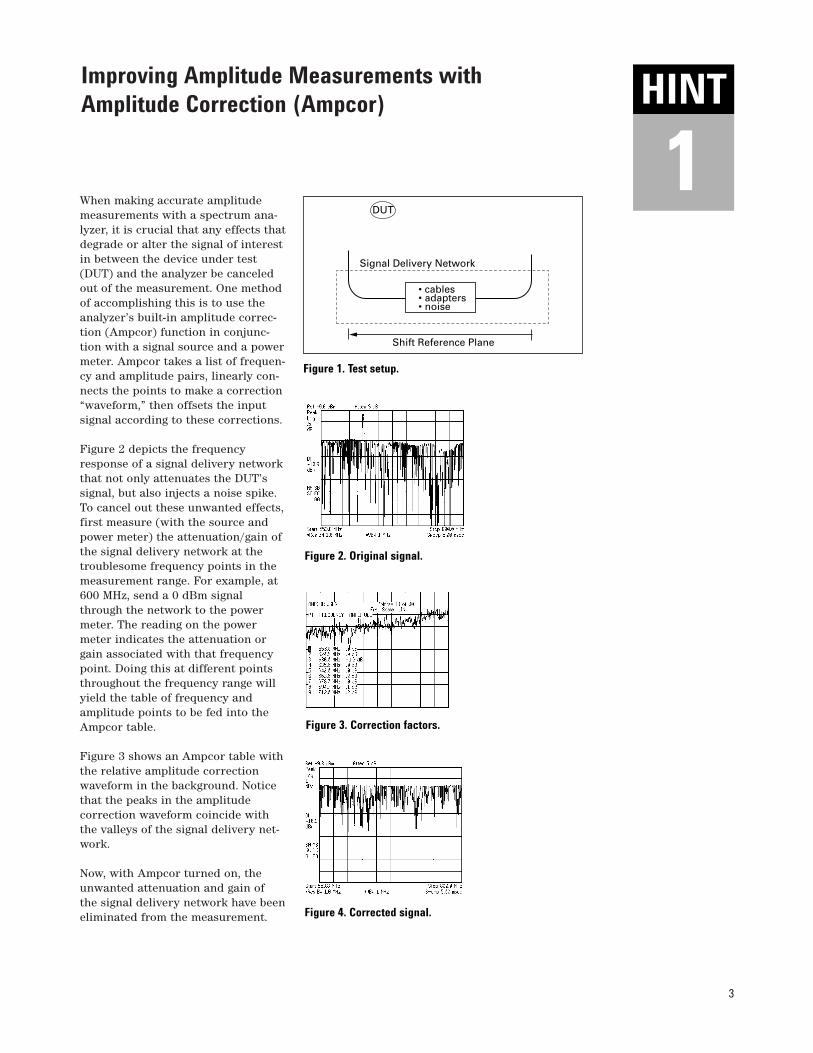
When making accurate amplitudemeasurements with a spectrum ana-lyzer, it is crucial that any effects thatdegrade or alter the signal of interestin between the device under test(DUT) and the analyzer be canceledout of the measurement. One methodof accomplishing this is to use theanalyzer’s built-in amplitude correc-tion (Ampcor) function in conjunc-tion with a signal source and a powermeter. Ampcor takes a list of frequen-cy and amplitude pairs, linearly con-nects the points to make a correction“waveform,” then offsets the inputsignal according to these corrections.
Figure 2 depicts the frequencyresponse of a signal delivery networkthat not only attenuates the DUT’ssignal, but also injects a noise spike.To cancel out these unwanted effects,first measure (with the source andpower meter) the attenuation/gain ofthe signal delivery network at thetroublesome frequency points in themeasurement range. For example, at600 MHz, send a 0 dBm signalthrough the network to the powermeter. The reading on the powermeter indicates the attenuation orgain associated with that frequencypoint. Doing this at different pointsthroughout the frequency range willyield the table of frequency andamplitude points to be fed into theAmpcor table.
Figure 3 shows an Ampcor table withthe relative amplitude correctionwaveform in the background. Noticethat the peaks in the amplitudecorrection waveform coincide withthe valleys of the signal delivery net-work.
Now, with Ampcor turned on, theunwanted attenuation and gain of the signal delivery network have beeneliminated from the measurement.
Improving Amplitude Measurements with Amplitude Correction (Ampcor)
DUT
• cables• adapters• noise
Shift Reference Plane
Signal Delivery Network
Figure 1. Test setup.
Figure 2. Original signal.
Figure 3. Correction factors.
Figure 4. Corrected signal.
HINT
1HINT
4
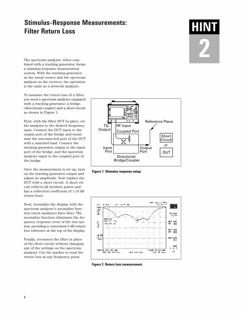
The spectrum analyzer, when com-bined with a tracking generator, formsa stimulus-response measurementsystem. With the tracking generatoras the swept source and the spectrumanalyzer as the receiver, the operationis the same as a network analyzer.
To measure the return loss of a filter,you need a spectrum analyzer equippedwith a tracking generator, a bridge,(directional coupler) and a short-circuitas shown in Figure 1.
First, with the filter DUT in place, setthe analyzer to the desired frequencyspan. Connect the DUT input to theoutput port of the bridge and termi-nate the unconnected port of the DUTwith a matched load. Connect thetracking generator output to the inputport of the bridge, and the spectrumanalyzer input to the coupled port ofthe bridge.
Once the measurement is set up, turnon the tracking generator output andadjust its amplitude. Now replace theDUT with a short circuit. A short cir-cuit reflects all incident power andhas a reflection coefficient of 1 (0 dBreturn loss).
Next, normalize the display with thespectrum analyzer’s normalize func-tion (most analyzers have this). Thenormalize function eliminates the fre-quency response error of the test sys-tem, providing a convenient 0 dB returnloss reference at the top of the display.
Finally, reconnect the filter in placeof the short circuit without changingany of the settings on the spectrumanalyzer. Use the marker to read thereturn loss at any frequency point.
Stimulus-Response Measurements: Filter Return Loss
RF Input
Coupled Port
Input Port
OutputPort
Reference Plane
DirectionalBridge/Coupler
Short Circuit
or
DUT
TGOutput
Figure 1. Stimulus response setup.
Figure 2. Return loss measurement.
HINT
2HINT

5
The spectrum analyzer’s ability tomeasure low-level signals is limitedby the noise generated inside thespectrum analyzer. This sensitivity tolow-level signals is affected by themeasurement setup.
Figure 1, for example, depicts a 50 MHzsignal that appears to be shrouded bythe analyzer’s noise floor.
The spectrum analyzer input attenu-ator and resolution bandwidth settingsare the key factors that determine howsmall of a signal the spectrum analyzercan measure.
The input attenuator, when activated,reduces the level of the signal at theinput of the mixer. An amplifier at themixer’s output then re-amplifies theattenuated signal to keep the signalpeak at the same point on the analyz-er’s display. In addition to amplifyingthe input signal, the noise present inthe analyzer is amplified as well. Thishas the effect of raising the displayednoise level of the analyzer.
The resolution bandwidth filter affectshow closely a small signal can be seenin the presence of a large one. Byincreasing the width of this filter,more noise energy is allowed to hitthe envelope detector of the analyzer.This also has the effect of raising thedisplayed noise level of the analyzer.
For maximum sensitivity, both theinput attenuator and resolution band-width settings must be minimized.Figure 2 shows the signal of Figure 1after the attenuator and resolutionbandwidth have been minimized.
If, after adjusting the attenuation andresolution bandwidth, a signal is stillnear the noise, stability of the dis-played trace can be improved byvideo averaging or video filteringthe display. Figure 3 shows the finalvideo averaged signal.
Measuring Low-Level Signals
Figure 1. Noise obscuring signal.
Figure 2. After minimizing attenuator andresolution bandwidth.
Figure 3. Signal after video averaging.
HINT
3HINT

6
High-level input signals may causeinternal spectrum analyzer distortionproducts that could mask the real dis-tortion measured on the input signal.Using dual traces and the analyzer’sRF attenuator, you can determinewhich signals, if any, are internallygenerated distortion products.
To identify these products, tune tothe second harmonic of the input sig-nal and set the input attenuator to 0 dBm. Next, save the screen data inTrace B, select Trace A as the activetrace, and activate Marker ∆. Thespectrum analyzer now shows thestored data in Trace B and the meas-ured data in Trace A, while Marker ∆shows the amplitude and frequencydifference between the two traces.Finally, increase the RF attenuationby 10 dB and compare the responsein Trace A to the response in Trace B.
If the responses in Trace A and TraceB differ, as in Figure 1, then the ana-lyzer’s mixer is generating internaldistortion products due to the highlevel of the input signal. In this case,attenuation is required.
In Figure 2, since there is no changein the signal level, the distortion isnot caused internally. The distortionthat is displayed is present on theinput signal.
Identifying Internal Distortion Products
Figure 1. Internally generated distortion products.
Figure 2. Externally generated distortion products.
HINT
4HINT

7
Modern spectrum analyzers utilize dig-ital technology for data acquisition andmanipulation. In these analyzers, theanalog signal at the input of the ana-lyzer is segmented into “bins,” whichare digitally sampled for further dataprocessing and display, as shown inFigure 1. The question that naturallyarises is: What point in the bin do weuse for our data point? Spectrum ana-lyzers generally have two or threedetector modes that dramaticallyaffect how the input signal is inter-preted and displayed.
Peak detection mode detects the high-est power level in each bin. Peakdetection is good for analyzing sinu-soids, but tends to over-respond tonoise when no sinusoids are present.
Sample detection mode displays thelast point in each bin, regardless ofpower. Sample detection is good fornoise measurements, and accuratelyindicates the true randomness ofnoise. Sample detection, however, isinaccurate for measuring continuouswave (CW) signals with narrowresolution bandwidths, and will misssignals that do not fall on the samepoint in each bin.
Negative Peak detection mode displaysthe lowest power level in each bin. Thismode is good for AM/FM demodulationand distinguishing between randomand impulse noise. Negative peak detec-tion does not give the analyzer bettersensitivity, although the noise floormay appear to drop.
Higher performance spectrum analyz-ers also have a detection mode calledrosenfell. This sampling mode dynam-ically classifies the data point as eithernoise or a signal, providing a bettervisual display of random noise thanpeak detection while avoiding themissed-signal problem of sampledetection.
Selecting the Best Display Detection Mode
Bin# 1 2 3 4 5 6 7
Positive detection Sample detection Negative detection
Figure 1. Sampling bins.
Figure 2. Detection modes.
HINT
5HINT

8
Analyzing burst signals (pulses) witha spectrum analyzer is very challeng-ing because in addition to displayingthe information carried by the pulse,the analyzer displays the frequencycontent of the shape of the pulse(pulse envelope) as well. The sharprise and fall times of the pulse enve-lope can create unwanted frequencycomponents that add to the frequencycontent of the original signal. Theseunwanted frequency components maybe so bad that they completelyobscure the signal of interest.
Figure 1, for example, depicts the fre-quency content of a pulse carrying asimple AM signal. In this case, the AMsidebands are almost completelyshrouded by spectral “noise” of thepulse envelope.
Time gated spectral analysis permitsanalysis of the contents of the pulsewithout the effect of the envelope ofthe pulse itself. As the name implies,time gating is achieved by placing agate (switch) in the video path of thespectrum analyzer as shown in Figure 2.
In a time gated measurement, theanalyzer senses when the burst starts,then triggers a delay so the resolutionfilter has time to react to the sharp risetime of the pulse, and finally stops theanalysis before the burst ends. By doingthis, only the information carried bythe pulse is analyzed, as is shown inFigure 3. It is now clear that our pulsecontained a 40 MHz carrier modulatedby a 100 kHz sinusoidal signal.
Measuring Burst Signals: Time Gated Spectrum Analysis
Attenuator
RampGenerator
InputFilter Mixer
Res. BW Filter Detector
Video Filter
LocalOscillator
Display
Y
X
RFInput
VCO
Gate
Figure 1. Signal without time gating.
Figure 3. Signal with time gating.
Figure 2. Spectrum analyzer block diagram with time gating.
HINT
6HINT

9
In addition to the swept-tuned fre-quency mode, spectrum analyzers canalso be used in the fixed-tuned mode(zero span) to provide time domainmeasurement capability much likethat of an oscilloscope.
One of the most powerful uses of zerospan is in making quick measure-ments of amplitude modulation.
To make AM measurements using zerospan, the center frequency of the ana-lyzer is set to the AM carrier frequencywhile the resolution bandwidth of theanalyzer is set so that it is wide enoughto pass the side-bands unattenuated,as shown in Figure 1. Then the analyzerspan is set to 0 Hz. This causes theanalyzer to stop sweeping and act asa fixed-tuned receiver, displaying sig-nal amplitude versus time as opposedto frequency versus time.
With the analyzer set to linear displaymode, the display shows the sinusoidalvariation in carrier amplitude due tothe amplitude modulation. Figure 2reveals that our carrier was modulatedby a 4 kHz sinusoidal signal.
The maximum modulation frequencythat may be resolved using zero spanis determined by the analyzer’s maxi-mum resolution bandwidth and itsminimum sweep time.
While zero span gives us the frequencyof the modulating signal, it tells usnothing about the quality of this signal.If your analyzer has a built-in fastfourier transform (FFT) function, per-form an FFT on the zero span signal ofFigure 2. Your analyzer will now showthe frequency content of the modulat-ing signal. In Figure 3, we see that thecarrier was indeed modulated by ahigh quality 4 kHz sinusoidal signal.
AM Measurements Using Zero Span and FFT
Figure 1. Resolution bandwidth setting.
Figure 2. Zero span.
Figure 3. FFT of zero span signal.
HINT
7HINT
10
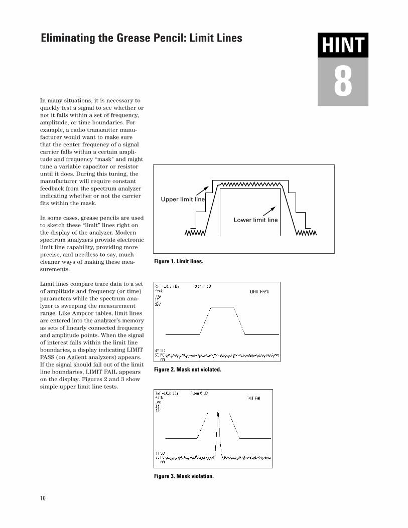
In many situations, it is necessary toquickly test a signal to see whether ornot it falls within a set of frequency,amplitude, or time boundaries. Forexample, a radio transmitter manu-facturer would want to make surethat the center frequency of a signalcarrier falls within a certain ampli-tude and frequency “mask” and mighttune a variable capacitor or resistoruntil it does. During this tuning, themanufacturer will require constantfeedback from the spectrum analyzerindicating whether or not the carrierfits within the mask.
In some cases, grease pencils are usedto sketch these “limit” lines right onthe display of the analyzer. Modernspectrum analyzers provide electroniclimit line capability, providing moreprecise, and needless to say, muchcleaner ways of making these mea-surements.
Limit lines compare trace data to a setof amplitude and frequency (or time)parameters while the spectrum ana-lyzer is sweeping the measurementrange. Like Ampcor tables, limit linesare entered into the analyzer’s memoryas sets of linearly connected frequencyand amplitude points. When the signalof interest falls within the limit lineboundaries, a display indicating LIMITPASS (on Agilent analyzers) appears.If the signal should fall out of the limitline boundaries, LIMIT FAIL appearson the display. Figures 2 and 3 showsimple upper limit line tests.
Eliminating the Grease Pencil: Limit Lines
Upper limit line
Lower limit line
Figure 1. Limit lines.
Figure 2. Mask not violated.
Figure 3. Mask violation.
HINT
8HINT

11
Agilent 8560 E-SeriesProviding high performance, capability,and quality for the most demandingmeasurements, these spectrum ana-lyzers have the performance and fea-tures you require on the R&D bench.
With the reliability and speed youdepend upon in production and theease-of-use, portability, and MIL-ruggedness you expect in the field,these analyzers will meet your highperformance needs.
Agilent 8590 E-SeriesThese application-specific spectrumanalyzers adapt to your evolving spec-trum analysis needs.
Optional hardware configurationsinclude time gating, EMI pre-compli-ance, scalar measurements, and digitaldemodulation for all major cellularand cordless formats.
Downloadable measurement person-alities add powerful measurementroutines.
(Updated measurement personalitiesnow conform to IS-136 NADC, J-STD-008 CDMA, and I-ETS 300 131 CT2communications standards.)
Agilent ESA-L1500A (Order number E4411A)Agilent sets a new performance stan-dard for low-cost spectrum analyzers.
The rain-resistant front panel andrugged packaging are designed formaking measurements in diverseweather conditions.
The automatic background calibrationand overload protection provideincreased measurement confidenceand reliability.
An enhanced user interface with alarge, high-resolution, active matrixLCD display makes measurementseasy to make and easy to see.
Agilent Portable Spectrum Analyzers
“One of them is ideal for what you want to do.”

Agilent Technologies’ Test and MeasurementSupport, Services, and AssistanceAgilent Technologies aims to maximize the value you receive, while minimizingyour risk and problems. We strive toensure that you get the test and measure-ment capabilities you paid for and obtainthe support you need. Our extensive sup-port resources and services can help youchoose the right Agilent products for yourapplications and apply them successfully.Every instrument and system we sell has a global warranty. Support is available for at least five years beyond the produc-tion life of the product. Two conceptsunderlie Agilent’s overall support policy:“Our Promise” and “Your Advantage.”
Our Promise“Our Promise” means your Agilent testand measurement equipment will meet itsadvertised performance and functionality.When you are choosing new equipment,we will help you with product informa-tion, including realistic performance spec-ifications and practical recommendationsfrom experienced test engineers. When
you use Agilent equipment, we can verifythat it works properly, help with productoperation, and provide basic measurementassistance for the use of specified capabil-ities, at no extra cost upon request. Manyself-help tools are available.
Your Advantage“Your Advantage” means that Agilentoffers a wide range of additional experttest and measurement services, which youcan purchase according to your uniquetechnical and business needs. Solve prob-lems efficiently and gain a competitive edgeby contracting with us for calibration, extra-cost upgrades, out-of-warranty repairs, andon-site education and training, as well as design, system integration, project man-agement, and other professional services.Experienced Agilent engineers and techni-cians worldwide can help you maximizeyour productivity, optimize the return oninvestment of your Agilent instruments andsystems, and obtain dependable measure-ment accuracy for the life of those products.
By internet, phone, or fax, get assistancewith all your test and measurement needs.
Online Assistancewww.agilent.com/find/assistPhone or FaxUnited States:(tel) 1 800 452 4844
Canada:(tel) 1 877 894 4414(fax) (905) 206 4120
Europe:(tel) (31 20) 547 2323(fax) (31 20) 547 2390
Japan:(tel) (81) 426 56 7832(fax) (81) 426 56 7840
Latin America:(tel) (305) 269 7500(fax) (305) 269 7599
Australia:(tel) 1 800 629 485 (fax) (61 3) 9210 5947
New Zealand:(tel) 0 800 738 378 (fax) (64 4) 495 8950
Asia Pacific:(tel) (852) 3197 7777(fax) (852) 2506 9284
Product specifications and descriptions in this document subject to change without notice.
Copyright © 1998, 2000 Agilent TechnologiesPrinted in U.S.A. 9/005965-7009E