for metal stamping presses - load monitors
TRANSCRIPT

PIEZO I/O MODULE
FOR METAL STAMPING PRESSES
& other Dynamically Loaded Machinery
PROFORCE
IMCO.US
MADE IN USA
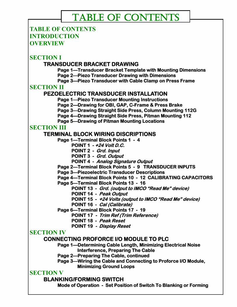
TABLE OF CONTENTS
INTRODUCTION
OVERVIEW
SECTION I TRANSDUCER BRACKET DRAWING Page 1—Transducer Bracket Template with Mounting Dimensions Page 2—Piezo Transducer Drawing with Dimensions Page 3—Piezo Transducer with Cable Clamp on Press Frame
SECTION II PEZOELECTRIC TRANSDUCER INSTALLATION Page 1—Piezo Transducer Mounting Instructions Page 2—Drawing for OBI, GAP, C-Frame & Press Brake Page 3—Drawing Straight Side Press, Column Mounting 112G Page 4—Drawing Straight Side Press, Pitman Mounting 112 Page 5—Drawing of Pitman Mounting Locations
SECTION III TERMINAL BLOCK WIRING DISCRIPTIONS Page 1—Terminal Block Points 1 - 4 POINT 1 - +24 Volt D.C. POINT 2 - Grd. Input POINT 3 - Grd. Output POINT 4 - Analog Signature Output
Page 2—Terminal Block Points 5 - 9 TRANSDUCER INPUTS Page 3—Piezoelectric Transducer Descriptions Page 4—Terminal Block Points 10 - 12 CALIBRATING CAPACITORS Page 5—Terminal Block Points 13 - 16 POINT 13 - Grd. (output to IMCO “Read Me” device) POINT 14 - Peak Output POINT 15 - +24 Volts (output to IMCO “Read Me” device) POINT 16 - Cal (Calibrate) Page 6—Terminal Block Points 17 - 19 POINT 17 - Trim Ref (Trim Reference) POINT 18 - Peak Reset POINT 19 - Display Reset
SECTION IV CONNECTING PROFORCE I/O MODULE TO PLC Page 1—Determining Cable Length, Minimizing Electrical Noise Interference, Preparing The Cable Page 2—Preparing The Cable, continued Page 3—Wiring the Cable and Connecting to Proforce I/O Module, Minimizing Ground Loops
SECTION V BLANKING/FORMING SWITCH Mode of Operation - Set Position of Switch To Blanking or Forming
TABLE OF CONTENTS

Our new, low cost small size (100mm x 80mm x 25mm) Proforce Piezo I/O Module with Peak Indicating is
D-Rail mounted and work in conjunction with any manufactures PLC or Industrial PC. Proforce Piezo I/O
Module is used for one (1) channel of Load Monitoring. They can work with any press tonnages or press
speeds.
The Proforce Piezo I/O Module offers the ability to customize Load Monitoring requirements by adapting
customized software programs. They can program load trip point for both Press and Dies. Hidden menus are
easily created to monitor press overload and die overloads for warranty purposes or other information that
may be required.
The Analog of the Proforce Piezo I/O Module feeds directly into the PLC or Industrial PC A to D Converter
Board. The output signal is 0 - 10 Volts. - 24 Volt input.
All types of IMCO's Piezoelectric Transducers are used with the Proforce Piezo I/O Module. Column
mounted, Pitman mounted and "Satellite" In-Die Transducers offer suitable mounting choices for the
Proforce Piezo I/O Module.
FEATURES COMPATIBLE WITH ANY MANUFACTURES PLC OR PC SIMULTANEOUSLY READS BOTH THE ANALOG TRACKING AND PEAK HIGH EACH MODULE OPERATES INDEPENDENTLY OF OTHER CHANNELS 0 - 10 VOLTS IMCO'S "ROCK SOLID " TECHNOLOGY FOR TEMPERATURE AND NOISE STABILITY D- RAIL MOUNTED
CUSTOMIZE PRODUCTION REQUIREMENTS BY CREATING ANY LOAD MONITORING FEATURES SMALL - SLEEK - COMPACT DESIGN
LOW COST - THROW AWAY CONCEPT FUNCTIONAL WITH ALL TYPES OF IMCO PIEZOELECTRIC TRANSDUCERS CAM SELECT MODULE FOR DOUBLE ACTION PRESS - TURNS PIEZOELECTRIC TRANSDUCERS ON AND OFF - optional
PROFORCE PIEZO
I/O MODULE
Sales Office 1190 Harrison Rd., #4, Santa Fe, NM 87507
Manufacturing 245 East Laraway Rd., Frankfort, IL 60423
Ph: 505-438-4344 Fax: 505-438-4364 E-Mail: [email protected]
IMCO.US

PROFORCE
PIEZO ANALOG-DIGITAL I/O MODULE
OVERVIEW
COPYRIGHT 2000
POWER ON
TRANSDUCER INPUT
TRIMMER GAIN CW—–>
●
PIEZOELECTRIC TRANSDUCERS TERMINAL BLOCK WIRING COMPRESSION A————–> A B————–> B TENSION B————–> A A————–> B
Make sure trimmer gain is in the minimum CCW position before calibrating. Normal Default position use calibrating capacitors to set calibration reading just below desired reading, then use trimmer gain to increase (INC.) signal for fine tuning. CW CLOCKWISE CCW COUNTERCLOCKWISE
MODEL NO. PZO-30AP
CALIBRATING CAPACITORS
● ●
●
IMCO 112G TRANSDUCER
COLUMN MOUNTED TENSION WIRING
( - ) GROUND
( - ) GROUND
OUTPUT SUGGESTION: USE EXTRA SHIELDED CABLE FROM TRANSDUCERS TO
RUN OUTPUT
(+)0—10V = 0—200%
+ 24V DC POWER
OUTPUT
BELDEN CABLE #8422
EXTRA TRANSDUCER INPUT
SHIELD
RED
BLACK
Terminal Block Description Points 13— 19 (see separate sheets)
GR
D
1
3
PE
AK
1
4
OU
TP
UT
+2
4 V
1
5
CA
L
16
TR
IM 1
7
RE
F.
PE
AK
1
8
RE
SE
T
DIS
PL
AY
RE
SE
T 1
9

TRANSDUCER BRACKET MOUNTING
Stick-on templates are supplied with all Proforce Piezo
I/O Modules. Determine the mounting bracket locations based on
the type of piezoelectric transducers to be used and the
optimum output mounting location for piezoelectric transducers
to be used. . Attach template to the chosen location . Drill and
tape the two appropriate holes using the self-adhesive bracket
mounting template (see Template No. 8010 ) to determine
correct hole spacing . Make sure that in drilling the holes, the
piezoelectric transducers will remain parallel to the mounting
surface (Example: column or pitman's). Use regular capacity 3/8
inch or 1/2 inch power drill; we suggest, if possible, a carbide
tipped drill bit, because the outer skin surface of the machine has
a tendency to be tempered hardened. Use a 1/8 IN.— 27 Inch
tapered (conical) pipe tape.
IMPORTANT:
DO NOT SUBSITIUTE A NON TAPERED TAPE
After drilling and tapping the holes, apply a light oil or grease for
lubrication and insert both top and bottom brackets; top brackets
have the lock nuts and should be mounted on top. Jam brackets
into frame with open end wrench so as to get square part of
bracket body as close as possible to column or frame of
Press . Do not remove the top bracket set screw when
jamming into press frame. Make sure brackets are tight. Lock
nuts should be “kissing” the frame or column.
NOTE:
Piezoelectric transducers are measuring micro strain in frame of
Press. Brackets should be tightened into Press frame as close as
possible to assure maximum piezoelectric transducer signal.
TORQUE TRANSDUCERS IN BRACKETS TO 15 INCH LBS.
SECTON I
Page 1
PROFORCE Piezo I/O Module
TRANSDUCER BRACKET MOUNTING TEMPLATE
PART NO. 8010
7.3 CM. 2 7/8 IN.
112G T/C
5.6 CM. 2 3/16 IN.
112 Y
5.1 CM. 2 IN. 112G
USE 8.7 MM DRILL 2 CM. DEEP
11/32 IN. DRILL 7/8 IN.DEEP 1/8 IN. 27
TAPERED PIPE TAPE
IMCO.US
245 East Laraway Road
Frankfort, IL 60423 U.S.A.
505-438-4344 PHONE
505-438-4364 FAX
WEB SITE: IMCO.US
COPYRIGHT 2005
4.8 CM. 1 7/8 IN.
112

The IMCO Load Monitor and piezoelectric transducers are ruggedly built to withstand normal
industrial environment conditions and require minimal maintenance. However, each system can
benefit from careful use and maintenance. It is recommended that the following procedure be
carried out at a minimum frequency of every three months.
TRANSDUCERS
Each piezoelectric transducer is factory pre-wired and terminal connections sealed. A visual
inspection of seal and connections is all that is required. Torque piezoelectric transducers to 15
inch/lbs. at time of installation or before calibration. They should not come loose even when
located on a moving connection and subjected to heavy shock. You can torque again to 15 inch/lbs.,
if any piezoelectric transducers screw becomes loose and the original calibration is maintained.
Check to see that top locknut remains securely fastened. If loose, tighten with regular wrench. A
small drop of LockTite or similar fluid should avoid future loosening of locknut.
TRANSDUCER BRACKET MOUNTING
PROFORCE Piezo I/O Module
SECTON I
Page 2

TRANSDUCER CABLES Check to see if cables are in good condition and covering remains pliable. Cracked or damaged
cable can cause erratic or lack of signal from piezoelectric transducers. Activation of each
piezoelectric transducer is easily checked on press by sharply squeezing top and bottom
piezoelectric transducer bracket. Hold sections between thumb and forefinger simulating a quick
pressure on the piezoelectric transducer as when the press member is dynamically loaded.
Appropriate meter needle (digital display) should indicate a response.
PROFORCE Piezo I/O Module
MAKE SURE FIRST CABLE CLAMP IS CLOSE TO TRANSDUCER AS DEPICTED TO ENSURE ADEQUATE STRAIN RELIEF.
SECTION I
Page 3
TRANSDUCER CABLE MOUNTING

Do not run any other AC or DC lines with the Piezoelectric Transducer
wires. Keep them separate.
Before serviceman arrives for Calibration be sure Proforce is mounted,
power connected, piezoelectric transducers are mounted and connected
to the Proforce I/O Module .
Software program should be written for Press PLC or Industrial PC is
the responsibility of the user.
Record Proforce I/O Module serial number for future reference.
PIEZOELECTRIC TRANSDUCER MOUNTING INSTRUCTIONS
The following instructions are provided in a basic sequence for simplicity in installing the Piezoelectric
Transducers on your machine . Please select appropriate reference to your type of machine and read
entire sequence before installing your Piezoelectric Transducers.
The IMCO piezoelectric transducers supplied from the factory for all IMCO systems are shipped
pre-wired. The standard pre-wired cables are determined by the mounting location either on the
columns or pitman's of the press. Standard cable lengths for column or pitman mountings are
applicable to most all types presses. Do not cut cable until length from transducers to the mounted
Proforce I/O Module is determined. If the cable lengths are not long enough, custom cable lengths can
be requested.
Typical mounting locations are recommended to obtain maximum output from IMCO piezoelectric
transducers. While there are possible alternates, it is suggested that you contact the factory before
selecting one. We do not advise pitman mounting if your pitman is split or it has an adjustment
mechanism in the pitman.
The IMCO piezoelectric transducers are measuring micro strain. Brackets should be tightened and
jammed into the press frame or pitman's as close as possible to assure maximum transducer signal.
Make sure the brackets remain parallel to the mounting surface (i.e. columns or pitman's). Use the
supplied mounting template to determine spacing distance between top and bottom mounting brackets.
SECTON II
Page 1
PIEZOELECTRIC TRANSDUCER
INSTALLATION on Stamping Presses
IMPORTANT
Please Read
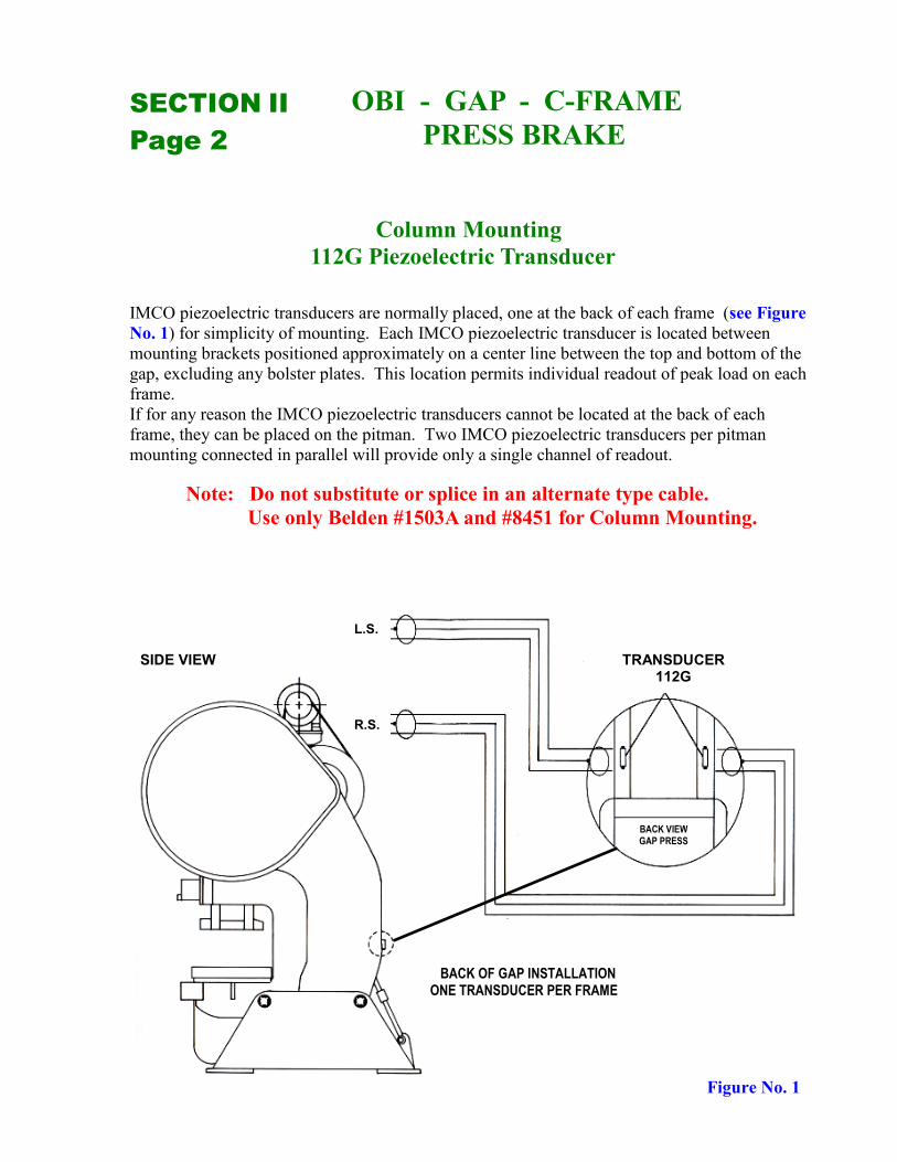
IMCO piezoelectric transducers are normally placed, one at the back of each frame (see Figure
No. 1) for simplicity of mounting. Each IMCO piezoelectric transducer is located between
mounting brackets positioned approximately on a center line between the top and bottom of the
gap, excluding any bolster plates. This location permits individual readout of peak load on each
frame.
If for any reason the IMCO piezoelectric transducers cannot be located at the back of each
frame, they can be placed on the pitman. Two IMCO piezoelectric transducers per pitman
mounting connected in parallel will provide only a single channel of readout.
Note: Do not substitute or splice in an alternate type cable.
Use only Belden #1503A and #8451 for Column Mounting.
OBI - GAP - C-FRAME
PRESS BRAKE SECTION II
Page 2
Column Mounting
112G Piezoelectric Transducer
Figure No. 1
SIDE VIEW
L.S.
R.S.
TRANSDUCER 112G
BACK VIEW GAP PRESS
BACK OF GAP INSTALLATION ONE TRANSDUCER PER FRAME

Location of IMCO piezoelectric transducers on straight side presses should be on the columns front and
back, (not the sides) away from keyways. One IMCO piezoelectric transducer for each column should be
mounted approximately on a center line between the top of the ram and the bottom of the bed, excluding
any bolster plates, to assure continued optimum output and positive response. (see Figure No. 2 and
Figure No. 3).
Note: Do not substitute or splice in an alternate type cable.
Use only Belden #1503A and #8451 for Column Mounting.
TOP VIEW - STRAIGHT SIDE PRESS
STRAIGHT SIDE PRESS Column Mounting
112G Piezoelectric Transducers
Figure No. 2
Figure No. 3
4-112G TRANSDUCERS ONE FOR EACH COLUMN
SIDE VIEW FRONT VIEW
LOCATION FOR MOUNTING TRANSDUCERS
APPROXIMATE
TRANSDUCER 112G
BACK
FRONT
TRANSDUCER 112G
SECTON II
Page 3

Attach two IMCO piezoelectric transducers on each pitman located 180 degrees from each other and as
close to the directional axis of rotation as possible. Wiring will be in parallel. We do not advise
pitman mounting if your pitman is split or it has an adjustment mechanism in the pitman. (see Figure
No. 4, Figure No. 5, Figure No. 6 and Figure No. 7)
Note: Do not substitute or splice in an alternate type cable.
Use only Belden #83319 for Pitman Mounting.
PITMAN VIEW
STRAIGHT SIDE PRESS Pitman Mounting
112 Piezoelectric Transducers
Figure No. 4
Figure No. 5
TWO TRANSDUCERS PER PITMAN
SIDE VIEW FRONT VIEW
FOR TRANSDUCER BRACKET SPACING REFER TO TEMPLATE PART NO. 8010
MAKE SURE TRANSDUCER(S) ARE MOUNTED SO AS TO MAINTAIN PARALLELISM WITH MACHINE MEMBER
TO CONTROL BOX
PRE-WIRED TRANSDUCERS ATTACH AS SHOWN
NOTE: TWO (2) TRANSDUCERS ONLY PER PITMAN MAY BE ATTACHED IN LOCATIONS 1-1, 2-2, 3-3, OR 4–4 DEPENDENT ON MOUNTING CONVENIENCE.
SECTION Z - Z
SECTON II
Page 4

Figure No. 6
Figure No. 7
WHITE TEFLON CABLE
SECTION Z - Z
ROTATION
LEFT SIDE PITMAN OR CONNECTING ROD
SECTION Z - Z
RIGHT SIDE PITMAN OR CONNECTING ROD
ROTATION
TO CONTROL BOX
TRANSDUCERS ARE PRE-WIRED IN PARALLEL, ATTACH AS SHOWN
NOTE: TWO (2) TRANSDUCERS PER PITMAN MAY BE ATTACHED IN LOCATIONS 1-1, 2-2, 3-3, OR 4-4 DEPENDENT ON MOUNTING CONVENIENCE.
PITMAN VIEW
PITMAN VIEW
SECTON II
Page 5
STRAIGHT SIDE PRESS Pitman Mounting
112 Piezoelectric Transducers

Terminal Block Points 1– 4
POINTS Description
+24 V D.C. Input from +24 Volt D.C. Power Supply
GRD. INPUT Ground Input from (-) terminal of 24 Volt
D.C. Power Supply.
GRD. OUTPUT Ground Output used with Point 4 Analog
Signature output.
ANALOG SIGNATURE OUTPUT 0 TO + - 10 VOLTS sometimes called
Track Output 0 to 100% or 0 to 200% Operation (see Calibrate Point (PT.) 16 for explanation and example)
1
2
3
4
1
2
3
PROFORCE PIEZO I/O MODULE
SECTON III
Page 1
4
WHITE
BLACK
SHIELD
COMPRESSION
COMPRESSION
WHITE
BLACK
112
SHIELD
TENSION
TENSION
BLACK
RED
RED
RED
112 IDS
SHIELD
LEFT REAR OR RIGHT REAR
5 A
6 B
7 S
5 A
6 B
7 S
5 A
6 B
7 S
A
B
5
A
6
B
7
S
8
A
9
B
TRANSDUCER INPUT
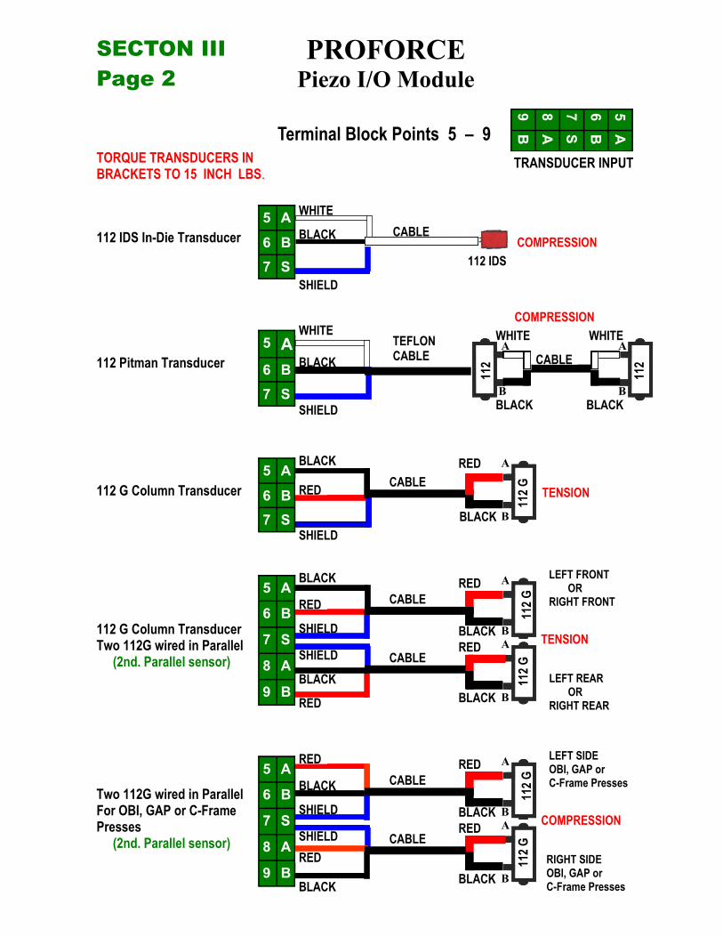
Terminal Block Points 5 – 9
LEFT FRONT OR RIGHT FRONT
WHITE
BLACK
TEFLON CABLE
CABLE
CABLE
A
B
BLACK
WHITE
112 IDS In-Die Transducer
112 Pitman Transducer
112 G Column Transducer
112 G Column Transducer Two 112G wired in Parallel (2nd. Parallel sensor)
5 A
6 B
7 S
8 A
9 B
PROFORCE Piezo I/O Module
RED
RED
RED
BLACK
BLACK
BLACK
SHIELD
CABLE
A
B
CABLE
CABLE
A
A BLACK
B BLACK
B
TORQUE TRANSDUCERS IN BRACKETS TO 15 INCH LBS.
SHIELD
112
G
112
G
112
G
112
SECTON III
Page 2
COMPRESSION
RED
RED
SHIELD
RIGHT SIDE OBI, GAP or C-Frame Presses
LEFT SIDE OBI, GAP or C-Frame Presses
Two 112G wired in Parallel For OBI, GAP or C-Frame Presses (2nd. Parallel sensor)
5 A
6 B
7 S
8 A
9 B
RED
RED
BLACK
BLACK
CABLE
CABLE
A
A BLACK
B BLACK
B
SHIELD
112
G
112
G

The Proforce Piezo I/O Module is capable of using any IMCO 112 Series Piezoelectric transducer and can be wired for tension or compression by switching the A + B points on the transducer input terminal block Points 5 through 9.
112 IDS In-Die Satellite Piezoelectric Transducer 112IDS are mounted in the hardened die plate under a section of die that has a critical load to be monitored. Multiply 112IDS transducers may be connected in parallel to increase signal strength and average the load from a wider area in the die. 112IDS transducers are wired for compression with Teflon cable, which is impervious to oil and maintains its flexibility. (wiring diagram “Terminal Block Points 5 through 9”, separate sheet)
112 Pitman Mounted Piezoelectric Transducer 112 are used on the connecting rods or pitman's of the press, because the stresses on the pitman's are greater than on the columns. The lower output 112 transducer is suitable for pitman mounting. Two (2) 112 transducers are pre-wired in parallel and mounted on each pitman or connecting rod. One (1) 112 transducer is mounted on the front of the pitman and the other is mounted on the back of the pitman, 180 degrees apart in the direction of the rotation compensating for bending of the pitman. Even though the 112 transducer is ideally suited for pitman mounting with its lower output, it does not limit its mounting use in other areas. 112 transducers are wired for compression with Teflon cable, which is impervious to oil and maintains its flexibility. (wiring diagram “Terminal Block Points 5 through 9”, separate sheet.)
112G Column Mounted Piezoelectric Transducer 112G transducers are used for column mounting in Single Point Straight Side Press (one pitman), Two Point Straight Side Press (two pitman’s) , Four Point Straight Side Press (four pitman’s) and the back of GAP, C-Frame, OBI, Press brakes. 112G transducers have three (3) times the output of the 112 transducer. When mounted on the columns of Presses the 112G transducers are wired for tension, When mounted on the back of GAP, C-Frame, OBI and Press Brakes the 112G transducer is wired for compression. The optimum way to monitor a Straight Side Presses is to use one (1) 112G transducer on each Press column and use one (1) Proforce Piezo I/O Module for each column being measured. IMCO recommends mounting 112G transducers on the front and back of the Press column halfway between the bed of the press and the top of the ram. We do not recommend mounting on the sides of the Press columns in order to reduce the chance of measuring bending which can occur on the side of some Presses. (wiring diagram “Terminal Block Points 5 through 9”, separate sheet)
112G Column Mounted Transducer wired in parallel (2nd Parallel Sensor) Two 112G transducers wired in parallel can be used on Two Point Straight Side Presses (two Pitman’s) using one (1) Proforce Piezo I/O Module and two (2)112G transducers wired in parallel to be mounted on the left front Press column and the left rear column. Then the same on the right front and right rear Press column ending up with a Proforce Piezo I/O Module for the (LS) left side and one for the (RS) right side of the Press, instead of one 112G transducer and one (1) Proforce Piezo I/O Module for each column of the Press. (wiring diagram “Terminal Block Points 5 through 9”, separate sheet)
5 A
6 B
7 S
8 A
9 B
Transducer Input Terminal Block Points 5 - 9
SECTON III
Page 3
PROFORCE PIEZO I/O MODULE
TRANSDUCER DESCRIPTIONS

POINTS Description
―A‖ TERMINAL FOR CALIBRATING CAPACITORS
NO CONNECTION
―B‖ TERMINAL FOR CALIBRATING CAPACITORS
Terminal Block Points 10 - 12
CALIBRATING CAPACITORS
12 B
11 C
10 A
The Calibrating Capacitors are used to reduce the output from the
piezoelectric transducers. During Calibration the more capacitance placed
across Points 10 and 12 , the less output the transducers will have. Once
the approximate reading is reached, use the Trimmer Gain Pot to fine tune
the capacitor settings. The best way to use the Trimmer Gain is to have it
set to the minimum full counter clock wise position before Calibrating
(normal position when shipped).
Set the calibrating capacitors readings for 10% or 15% lower than the
desired calibrate reading. Once the calibrating capacitors are set between
Point A & B, the Trimmer Gain can then be double for that reading. It is
always best to get as close to the reading with the calibrating capacitors,
before adding the Trimmer Gain, because the Gain goes up and not down.
After completing the Calibration, log the calibration values and use Trim
Ref. Point 17 to establish how much Trimmer Gain was used for fine
adjustment. This is helpful for changing a Proforce I/O Module without
recalibrating.
10 A
11 C
12 B
PROFORCE Piezo I/O Module
SECTON III
Page 4

Terminal Block Points 13—16
POINTS Description
GRD. Ground (output to IMCO ―Read Me‖ device)
PEAK OUTPUT 0—10 Volts = 200% Highest output signal held until reset by Peak Reset.
The signal remains available to read for PC or PLC with a slower Analog to Digital Converter Board or Modular. The PC or PLC then resets the Peak Output Signal by momentarily connecting Peak Reset Point 18 to GRD (ground). This resets the Peak Reading to 0 Volts preparing it for the next stroke.
NOTE: The Peak Output Signal can also be read directly on voltmeters. The reading is then reset by connecting the Display Reset Point 19 to the Ground Point 13 through a normally open push button switch.
+24V +24 Volts (output to IMCO ―Read Me‖ device)
CAL Calibrate The Calibrate Point when connected to GRD (ground) through a
normally open switch feeds a 1 Volt signal into the piezoelectric transducer input, providing a test signal to the Proforce Piezo I/O Module to assure its operation and provides a standard input to output calibration reference. While the Calibrate Switch is held closed, the output signal should read approximately 5 Volts on the Peak Output Point 14 and 5 Volts on Point 4 of the Analog Output, sometimes referred as the Track Output. The 5 Volts represent 50% of the 0 - 10 Volt signal, if you are using 10 Volts to represent 100% Doing this means that a 1 Volt output from the piezoelectric transducer will provide 5 Volts or a 50% reading from the Proforce Piezo I/O Module and the 2 Volt output from the piezoelectric transducer will provide a 10 Volt output from the Proforce Piezo I/O Module representing 100%. Another method of using the 1 Volt Calibrate reference is to let the 1 Volt represents 100% or 5 Volts on the output. Choosing to let 5 Volts represent 100% on the Proforce Piezo I/O Module output allows the additional 5 Volts to 10 Volts range to read overloads from 100% to 200%. This provides the over range capability when displaying loads on Stamping Presses.
Example: A Press operating a 95% load and the overload limit is set to 199% and can be set no higher,
If a 20% overload occurred, you would not be able to capture and display the 115% load if 10 Volts equaled 100%. You could not display any readings above 100% or 10 Volts. You would have no idea how much the load was exceeded above 100% without an over range capacity.
13
14
19
18
17
16
15
14
13
PROFORCE PIEZO I/O MODULE
16
15
SECTON III
Page 5

Terminal Block Points 17—19
POINTS Description
TRIM REF
PEAK RESET
DISPLAY RESET
19
18
17
16
15
14
13
17
18
19
PROFORCE PIEZO I/O MODULE
SECTON III
Page 6
Trim Reference The Trim Ref. when connected to GRD (ground) through
a normally open switch provides a method of determining how much trimmer gain is used when calibrating. It provides a reference number in either volts or percent which allows for a replacement Proforce Piezo I/O Module to be installed without recalibrating. If using a Volt Meter to read Terminal Block Point 4 Analog Track Output, the reading should be from 5 Volts for no Trimmer Gain to 7.50 Volts for full Trimmer gain. If reading using an IMCO hand held ―READ ME‖
Peak Reset The Peak Reset is needed to reset the Peak Detector circuit
after a PC, PLC or Volt Meter display has captured the PEAK Reading. A momentary connection of the Peak Reset Point 18 to GRD (ground) will reset the Peak and prepare the Proforce Piezo I/O Module to capture a new reading for the next cycle of the press.
Display Reset The Display Reset when connected momentarily to GRD
(ground) Point 13 through a normally open switch is used to reset the calibrate signal. The Calibrate Reference Signal is a simulated signal and requires the resetting of both the Peak Detector and the Test Signal. The Test Signal cleared by resetting the Piezoelectric Transducer Input. The Display Reset can be used to reset the Peak Detector, keeping in mind, that it also clears the Piezoelectric Transducer Input. Any Output Signal to the Analog Track Output Point 4 will be disrupted, such as taking a Signature Reading. Also in some situations, where the Piezoelectric Transducer could detect extra unwanted mechanical stresses, clearing the Piezoelectric Transducer Input and the Peak Detector at the same time can be beneficial, as long as disruption to the Analog Track Output Point 4 in not a problem. The Display Reset is also used to reset the display on the IMCO hand held
“READ ME” Device.
The Display Reset can be controlled by a PC or PLC by momentarily connect-ing Point 19 to GRD (ground).

CONNECTING I/O MODULE TO PLC
DETERMINING CABLE LENGTH
When you determine the length of cable required to connect Proforce I/O Module, remember to include additional
length to route the drain wire and foil shield to earth ground. Route cable long enough to avoid signal attenuation..
MINIMIZING ELECTRICAL NOISE INTERFERENCE
High speed analog signals are particularly vulnerable to electrical noise. Take precautions
when routing signal cables. To help reduce the effects of electrical noise on analog signals, we
recommend that you:
Install the PLC AND Proforce I/O Module in a NEMA rated enclosure.
Make sure that the PLC and Proforce I/O Module is properly grounded.
Use Belden cable # 1503A, # 8451 or #8761 (or equivalent) for signal wiring.
Ground the cable properly.
Route signal cables away from other wiring or in grounded conduit.
Group Proforce I/O Modules away from AC or high-voltage DC modules.
We recommend re-checking Proforce I/O modules operation after installing new machinery or
other sources of electrical noise near the I/O Modules.
ATTENTION: Before wiring a Proforce I/O Module, disconnect
Power from the I/O Module and from any other
Power source to the module.
PREPARING THE CABLE
1. At each end of the cable, strip about 3 inches ( 76.19 mm) of casing to expose the wires.
2. At the ground end of the cable (Figure 1), twist the drain wire and the foil shield together and bend them away from
the cable. Using a hot air blower, apply shrink wrap where wires leave the casing.
3. At the other end of the cable, cut off the drain wire and foil shield. Apply shrink wrap to the junction where wires
leave casing.
4. Trim the signal wires to 2 inch (50.8 mm) lengths. Strip about 3/16 inch (4.76 mm) of insulation away to expose the
copper strands for connections.
5. Decide where you will connect the cable to earth ground, and ground it. Refer to GROUNDING THE CABLE.
6. Connect signal wire (black and white) to terminal block and to input or out put device. (see separate sheets for Wiring
Terminal Block Points 1 through 19).
PROFORCE Piezo I/O Module
SECTON IV
Page 1

CONNECTING I/O MODULE TO PLC
GROUNDING THE CABLE
Signal cable such as Belden #1503A, #8451 and #8761 ( or equivalent) has two signal wires (black and white), one drain wire
and a Foil shield (Figure 2). The drain wire and foil shield must be grounded at only one end of the cable, not at both ends.
IMPORTANT: Ground the cable shield at one end having a good earth ground connection, such as at an I/O chassis
mounting bolt or nearest ground bus in the I/O enclosure. Make this connection as short as possible. Do not ground the
cable at the input to the A to D Board.
Black Wire
Figure 1
Shrink Wrap
Shrink Wrap White Wire
Insulation
White Wire
Black Wire
Casing
Casing
Grounded End
UnGrounded End
Twisted Foil Shield and Drain
Black Wire
Repeat steps 1— 6 for each channel.
For each unused input channel, follow your A to D Board Instruction Manual.
Continued: Preparing The Cable
White Wire
Black Wire Shrink Wrap
Insulation
Drain Wire
Foil Shield
Figure 2
PROFORCE Piezo I/O Module
SECTON IV
Page 2

To keep the ground-loop current of input circuits to a minimum, we recommend that you:
Use the same power supply to power both input channels of a Proforce I/O Module
Or Tie together the grounds of separate power supplies
CONNECTING I/O MODULE TO PLC
ATTENTION: Before wiring the Proforce I/O Module, disconnect
PLC System power, I/O Rack power, and module power.
WIRING THE CABLE
0
1
2
3
4
5
6
7
8
9
10
11
MINIMIZING GROUND LOOPS
IN 0 + IN 0 - ANL COM IN 1 + IN 1 - ANL COM Not used OUT 0 ANL COM Not used OUT 1 ANL COM
CONNECT TO PROFORCE I/O MODULE
IMPORTANT: Follow A to D Board
Instruction Manual
for unused inputs.
Earth Ground
Use appropriate terminal block points, depending on the speed of A to D Board
For Faster A to D Board Connect to Point 4 Analog Signature
Output (+) and Point 3 Ground Output
(-).
OR
For Slower A to D Board Connect Point 14 Peak Output (+) and
Point 13 or 3 Ground (-).
Note: Use Point 18 to Ground to reset
the Peak Detector after each cycle of
Press to reset readings of Peak Detector
using a PLC output or Electronic Cam
to prepare the Peak Output Signal
Capture for the next Cycle of the Press.
PROFORCE Piezo I/O Module
SECTON IV
Page 3

BLANKING/FORMING SWITCH
The blanking of very heavy metal.
BLANKING FORMING
Presses normally running above 600 SPM.
Presses normally running from 5 SPM to 600 SPM.
The forming of very deep drawn parts.
The normal mode of operation is the Forming Mode and the Switch should only be used in the less sensitive Blanking Mode for high speed press run-ning 600 SPM to 2500 SPM or extremely heavy blanking operations.
Normal Mode
Normal Mode
FOR
PROFORCE Piezo I/O Module
SECTON V
FOR