for mobile applications - bosch global · 2 days ago · table 2: risk classes according to ansi...
TRANSCRIPT

Control blocksfor mobile applications
Applies to the following types:M1
M4
M6
M7
M8
M9
MO
RS
SM
SP
SX Replaces: 03.2014English
Operating instructionsRE 64025-B/10.2014
MO
RSSX
M4M1 M6
SP
M7
SM
M8 M9

The data specified above only serve to describe the product. No statements concerning a certain condition or suitability for a certain application can be derived from our information. The information given does not release the user from the obligation of own judgment and verification. It must be remembered that our products are subject to a natural process of wear and aging.
© This document, as well as the data, specifications and other information set forth in it, are the exclusive property of Bosch Rexroth AG. It may not be reproduced or given to third parties without its consent.
The cover shows an example configuration. The product supplied may therefore differ from the photo shown.
The original operating instructions were prepared in German.

RE 64025-B/10.2014, control blocks, Bosch Rexroth AG
3/52 Contents
Contents
1 About this documentation 51.1 Validity of the documentation 51.2 Required and amending documentation 51.3 Representation of information 71.3.1 Safety instructions 71.3.2 Symbols 81.3.3 Designations 81.3.4 Abbreviations 82 Safety instructions 92.1 General information on this chapter 92.2 Intended use 92.3 Improper use 102.4 Qualification of personnel 102.5 General safety instructions 102.6 Product-specific safety instructions 112.7 Personal protective equipment 133 General information on damage to property and damage to the product 144 Scope of delivery 165 About these products 175.1 Performance description 175.2 Product description 175.3 Product identification 176 Transport and storage 196.1 Transporting the control block 196.1.1 Transport by hand 196.1.2 Transport using lifting tools 196.2 Storing the control block 217 Assembly 237.1 Unpacking 237.2 Painting the control block 237.3 Installation conditions 247.4 Installation position 247.5 Assembling the control block 247.5.1 Required tools 247.5.2 Preparation 247.5.3 Dimensions 247.5.4 Fastening the control block 257.5.5 Completing the assembly 267.5.6 Connecting the control block mechanically 267.5.7 Connecting the control block hydraulically 277.5.8 Connecting the control block electrically 298 Commissioning 308.1 Before first commissioning 318.2 First commissioning 328.3 Re-commissioning after standstill 33

4/52
Bosch Rexroth AG, control blocks, RE 64025-B/10.2014
Contents
9 Operation 349.1 Information on the use of control blocks at low temperatures 3410 Maintenance and repair 3610.1 Inspection 3810.2 Maintenance 3810.3 Repair 3810.4 Spare parts 3911 Disassembly and exchange 4011.1 Necessary tools 4011.2 Preparing disassembly 4011.3 Disassembling the control block from the machine 4011.4 Preparing the components for storage/further use 4012 Disposal 4113 Extension and modification 4214 Troubleshooting 4314.1 How to proceed for troubleshooting 4314.2 Fault table 4415 Technical data 4616 Index 48

About this documentation 5/52
RE 64025-B/10.2014, control blocks, Bosch Rexroth AG
1 About this documentation
1.1 Validity of the documentationThis documentation applies to the following products: • M1 • M4 • M6 • M7 • M8 • M9
• MO • RS • SM • SP • SX
This documentation is aimed at the machine manufacturer.This documentation contains important information on the safe and proper transport, assembly and disassembly, commissioning, operation, maintenance and simple troubleshooting of the product.
▶ You should read this documentation thoroughly and in particular chapter 2 "Safety instructions" on page 9 and chapter 3 "General information on damage to property and damage to the product" on page 14 before working with the control block.
This documentation applies to all control blocks of the listed series irrespective of their date of production until a new revision of this document is issued.
1.2 Required and amending documentation ▶ Do not commission the product until you have been provided with the
documentation marked with the book symbol relating to your Rexroth product and you have understood and observed it.
Table 1: Required and amending documentation
Title Document number Document typeOpen center control block MO-16, 22, 32 64354 Data sheet
Open center control block MO-40 64370 Data sheet
Open center control block MO-52 64373 Data sheet
Open center control block M1 64263 Data sheet
Open center control block M8 64294 Data sheet
Open center control block M9 64303 Data sheet
Open center control block SM 64122 Data sheet
Load-sensing control block M4-12 64276 Data sheet
Load-sensing control block M4-15 64283 Data sheet
Load-sensing control block M4-22 64279 Data sheet
Load-sensing control block SP-08 64139 Data sheet
LUDV control block M6-15 64321 Data sheet
LUDV control block M6-22 64322 Data sheet
LUDV control block M7-22 64295 Data sheet
LUDV control block M7-25 64297 Data sheet
LUDV control block RS12 64133 Data sheet
LUDV control block RS14 64136 Data sheet
LUDV control block RS15 64134 Data sheet

6/52 About this documentation
Bosch Rexroth AG, control blocks, RE 64025-B/10.2014
Table 1: Required and amending documentation
Title Document number Document type
LUDV control block SX 10 64132 Data sheet
LUDV control block SX 12 64128 Data sheet
LUDV control block SX 14 64125 Data sheet
Order confirmationContains the order-specific technical data of your control block.
Order confirmation
Quotation drawingContains the external dimensions, all connections and the hydraulic circuit diagram of your control block.
Quotation drawing
Hydraulic fluids based on mineral oils and related hydrocarbonsDescribes the requirements on hydraulic fluids based on mineral oil and related hydrocarbons for operation with Rexroth hydraulic components and helps you to select a hydraulic fluid for your Bosch Rexroth component.
90220 Data sheet
Environmentally compatible hydraulic fluidsDescribes the requirements on environmentally compatible hydraulic fluids for operation with Rexroth hydraulic components and helps you to select a hydraulic fluid for your Bosch Rexroth component.
90221 Data sheet
MTTFd reliability characteristics regarding the functional safety according to ISO 13849MTTFd values for control blocks
90290 Data sheet
Further information is available from Rexroth and at www.boschrexroth.de/mobilhydraulik-katalog.

About this documentation 7/52
RE 64025-B/10.2014, control blocks, Bosch Rexroth AG
1.3 Representation of informationConsistent safety instructions, symbols, terms and abbreviations are used in this documentation so that you can quickly and safely work with your product. For a better understanding, they are explained in the following sections.
1.3.1 Safety instructionsIn this documentation, safety instructions are included in chapter 2.6 "Product-specific safety instructions" on page 11 and in chapter 3 "General information on damage to property and damage to the product" on page 14 or whenever a sequence of actions or instructions is explained which bears the risk of personal injury or damage to property. The hazard avoidance measures described must be observed.
Safety instructions are set out as follows:
SIGnAl wORDType and source of danger!Consequences in case of non-compliance
▶ Hazard avoidance measures ▶ <Enumeration>
• warning sign: Draws attention to the danger • Signal word: Identifies the degree of danger • Type and source of danger: Specifies the type and source of danger • Consequences: Describes the consequences of non-compliance • Precaution: Specifies how the danger can be prevented
Table 2: Risk classes according to AnSI Z535.6-2006
warning sign, signal word Meaning
DAnGER Indicates a dangerous situation which will cause death or severe personal injuries if not avoided.
wARnInG Indicates a dangerous situation which may cause death or severe personal injuries if not avoided.
CAUTIOn Indicates a dangerous situation which may cause minor or medium personal injuries if not avoided.
NOTICE Damage to property: The product or the environment could be damaged.

8/52 About this documentation
Bosch Rexroth AG, control blocks, RE 64025-B/10.2014
1.3.2 SymbolsThe following symbols indicate notices which are not safety-relevant but increase the comprehensibility of the documentation.
Table 3: Meaning of the symbols
Symbol MeaningIf this information is not observed, the product cannot be used and/or operated optimally.
▶ Individual, independent action
1. 2. 3.
Numbered instruction:The numbers indicate that the actions must be carried out one after the other.
1.3.3 DesignationsThe following designations are used in this documentation:
Table 4: Designations
Designation MeaningMono block Control block which is molded in one piece. Optionally, further directional
valves can be mounted to extend the functions.Directional valve Control block element with 1 spool axis, in the following also referred to as
"control block disc".Control spool Main spool
Actuation Type of control of the control spool
1.3.4 AbbreviationsThe following abbreviations are used in this documentation:
Table 5: Abbreviations
Abbreviation MeaningDB Pressure relief valve (Druckbegrenzungsventil)
DIN Deutsche Industrie Norm (German Industry Standard)
ISO International Organization for Standardization

Safety instructions 9/52
RE 64025-B/10.2014, control blocks, Bosch Rexroth AG
2 Safety instructions
2.1 General information on this chapterThe product has been manufactured according to the generally accepted codes of practice. However, there is still the risk of personal injury and damage to property if you do not observe this chapter and the safety instructions in this documentation.
▶ Read this documentation completely and thoroughly before working with the product.
▶ Keep this documentation in a location where it is accessible to all users at all times.
▶ Always include the required documentation when you pass the control block on to third parties.
2.2 Intended useControl blocks are hydraulic components and are therefore neither covered by the scope of completely nor partly completed machinery in the sense of the EU Machinery Directive 2006/42/EC. The component is exclusively intended to be assembled together with other components to form partly completed or complete machinery. The component may only be commissioned if it has been integrated in the machine for which it is designed and if the safety of the overall system was established according to the requirements of the Machinery Directive.
The control blocks specified in chapter 1.1 have been developed for the control of different hydraulic actuators in mobile machines. Any deviating use is only permitted after consultation with Bosch Rexroth.
The product can be used as safety-relevant part of a control system. It does, however, not include any safety functions because they cannot be implemented self-dependently by the product. If the product is used for the implementation of safety functions, additional measures with regard to control and/or the safety-related part of the control must be specified by the system manufacturer or system planner. Further information is available in the standards for functional safety such as ISO 13849, IEC 62061 or specific professional guidelines.
▶ Comply with the technical data, application and operating conditions and performance limits according to data sheet and order confirmation. For information on the permitted hydraulic fluids, see the respective data sheet.
The control block is not a piece of safety equipment. Intended use includes having read and understood this documentation completely, especially chapter 2 "Safety instructions" on page 9.

10/52 Safety instructions
Bosch Rexroth AG, control blocks, RE 64025-B/10.2014
2.3 Improper useAny use deviating from the intended use is improper and thus not admissible.The valve is not suitable for being operated in explosive environments.Bosch Rexroth AG does not assume any liability for damage caused by improper use. The user assumes all risks involved with improper use.
2.4 Qualification of personnelThe activities described in this documentation require basic knowledge of mechanics, electrics and hydraulics as well as knowledge of the appropriate technical terms. For transporting and handling the product, additional knowledge of how to handle lifting tools and the necessary attachment devices is required. Experts are those who can recognize potential dangers and apply the appropriate safety measures due to their technical training, knowledge and experience, as well as their understanding of the relevant provisions pertaining to the work to be undertaken. An expert must observe the relevant specific professional rules and have the necessary hydraulic expert knowledge.Hydraulic expert knowledge means, amongst others: • Reading and understanding hydraulic schemes • Having knowledge of the function and interaction of hydraulic components
Bosch Rexroth offers measures supporting the training in specific fields. Please find an overview of the training contents on the Internet at: http://www.boschrexroth.de/didactic
2.5 General safety instructions • Observe the valid regulations on accident prevention and for environmental protection.
• Observe the safety regulations and provisions of the country where the product is implemented/used.
• Exclusively use Rexroth products in technically perfect condition. • Observe all notices on the product. • Persons who assemble, operate, disassemble or maintain Rexroth products must not be under the influence of alcohol, drugs or pharmaceuticals that may affect their ability to respond.
• Only use original Rexroth accessories and spare parts. • Comply with the technical data and environmental conditions indicated in the product documentation.
• The installation or use of inappropriate products in safety-relevant applications could result in uncontrolled operating conditions during operation. This may cause injuries and/or damage to property. Therefore, only use a product for safety-relevant applications if this use is expressly specified and permitted in the documentation of the product, e.g. in explosion-protected areas or in safety-related parts of control systems (functional safety).
• Do not commission the product until you can be sure that the end product (for example a machine/system) in which the Rexroth products are to be installed comply with the country-specific provisions, safety regulations and standards of the application.

Safety instructions 11/52
RE 64025-B/10.2014, control blocks, Bosch Rexroth AG
2.6 Product-specific safety instructionsThe following safety instructions apply to chapters 6 to 14.
wARnInGUnintended pressure build-up/pressure reduction!Danger to life, risk of injury, damage to property!The control block may block in an undefined position due to internal contamination, e.g. polluted hydraulic fluid, abrasion or residual dirt from system components. As a result, the driven actuator is no longer under the operator’s control.
▶ Secure the machine against rolling (away) and unintended movements according to the machine manufacturer's specifications.
▶ Comply with the specified cleanliness class for the hydraulic fluid according to the data sheet.
Hydraulic fluid leaking through cracks in the housing, leaks between control block and/or attachment parts due to the use of an inadmissible pressure medium, adjustment work at seal lock nuts, cleaning with solvents and thus destruction of seals!Danger to life and risk of injury due to injection of a pressurized oil jet! Risk of burning due to escaping oil!
▶ Access to the control blocks during operation must be limited in such a way that hazards to persons caused by the bursting during operation is avoided by suitable safeguards.
▶ Depressurize the control block and repair the leak.
Pressurized machine!Danger to life, risk of injury, severe injury when working at machines that have not been stopped! Damage to property!
▶ Secure the overall system according to the manufacturer's instructions. ▶ Make sure that the control block has been depressurized. For doing so, observe
the specifications of the machine manufacturer. ▶ Do not disconnect lines, connections or components as long as the control
block is under pressure. ▶ Observe the specifications of the machine manufacturer regarding
machine shut-down.
Danger due to suspended loads!Danger to life, risk of injury, damage to property!In case of improper transport, the control block may fall down and cause injuries e.g. crush injuries or fractures and/or damage to the product.
▶ Make sure that the lifting capacity of the forklift and/or the lifting tool is sufficient.
▶ Never step or reach below suspended loads. ▶ Provide for a stable position during transport. ▶ Use your personal protective equipment (e.g. safety goggles, protective gloves,
suitable working clothes, safety shoes). ▶ Use suitable lifting tools for the transport. ▶ Observe the prescribed position of lifting straps. ▶ Comply with the national laws and regulations regarding occupational health
and safety and transport.
12/52 Safety instructions
Bosch Rexroth AG, control blocks, RE 64025-B/10.2014
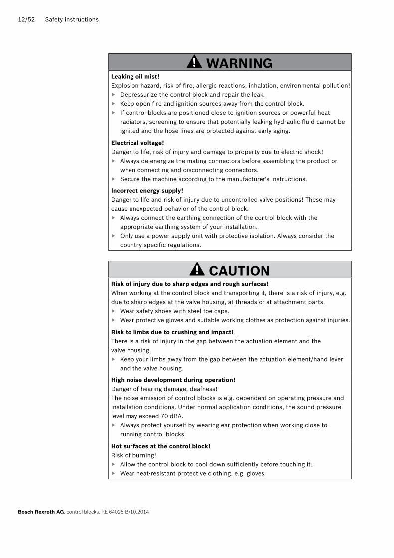
wARnInGleaking oil mist!Explosion hazard, risk of fire, allergic reactions, inhalation, environmental pollution!
▶ Depressurize the control block and repair the leak. ▶ Keep open fire and ignition sources away from the control block. ▶ If control blocks are positioned close to ignition sources or powerful heat
radiators, screening to ensure that potentially leaking hydraulic fluid cannot be ignited and the hose lines are protected against early aging.
Electrical voltage!Danger to life, risk of injury and damage to property due to electric shock!
▶ Always de-energize the mating connectors before assembling the product or when connecting and disconnecting connectors.
▶ Secure the machine according to the manufacturer's instructions.
Incorrect energy supply!Danger to life and risk of injury due to uncontrolled valve positions! These may cause unexpected behavior of the control block.
▶ Always connect the earthing connection of the control block with the appropriate earthing system of your installation.
▶ Only use a power supply unit with protective isolation. Always consider the country-specific regulations.
CAUTIOnRisk of injury due to sharp edges and rough surfaces!When working at the control block and transporting it, there is a risk of injury, e.g. due to sharp edges at the valve housing, at threads or at attachment parts.
▶ Wear safety shoes with steel toe caps. ▶ Wear protective gloves and suitable working clothes as protection against injuries.
Risk to limbs due to crushing and impact!There is a risk of injury in the gap between the actuation element and the valve housing.
▶ Keep your limbs away from the gap between the actuation element/hand lever and the valve housing.
High noise development during operation!Danger of hearing damage, deafness!The noise emission of control blocks is e.g. dependent on operating pressure and installation conditions. Under normal application conditions, the sound pressure level may exceed 70 dBA.
▶ Always protect yourself by wearing ear protection when working close to running control blocks.
Hot surfaces at the control block!Risk of burning!
▶ Allow the control block to cool down sufficiently before touching it. ▶ Wear heat-resistant protective clothing, e.g. gloves.

Safety instructions 13/52
RE 64025-B/10.2014, control blocks, Bosch Rexroth AG
CAUTIOnCold surfaces at the control block!Sticking skin to and frostbites caused by contact with the cold valve housing!
▶ Wear personal protective clothing, e.g. cold protection gloves.
Improper laying of cables and lines!Risk of stumbling and damage to property!
▶ Lay cables and lines in such a way that they cannot be damaged and no one can trip over them.
Contact with hydraulic fluid!Health hazard/impairment of health, e.g. eye injuries, skin lesions, poisoning due to inhalation!
▶ Avoid contact with hydraulic fluids. ▶ When dealing with hydraulic fluids, you must imperatively observe the safety
instructions of the lubricant manufacturer. ▶ Use personal protective equipment (like e.g. safety goggles, protective gloves,
suitable working clothes, safety shoes). ▶ If hydraulic fluid comes into contact with the eyes or enters the bloodstream or
is swallowed nevertheless, consult a doctor immediately.
Escaped hydraulic fluid due to leakage!Slip hazard!
▶ Pay attention to escaped hydraulic fluid on the ground around the machine. ▶ If hydraulic fluid has leaked, use an oil binding agent. ▶ Dispose of the hydraulic fluid in accordance with the applicable national
regulations in your country.
2.7 Personal protective equipmentThe user of the control block is responsible for the personal protective equipment. Observe the safety regulations and provisions in your country.Bosch Rexroth recommends using the following personal protective equipment when using the product: • Heat-resistant protective clothing, e.g. protective gloves for working at the control block
• Safety shoes, protective gloves, safety goggles, ear protection and suitable working clothes for working at the control block

14/52 General information on damage to property and damage to the product
Bosch Rexroth AG, control blocks, RE 64025-B/10.2014
3 General information on damage to property and damage to the product
The warranty only applies to the delivered configuration.The claim to warranty expires in case of: • Incorrect assembly, commissioning and operation • Improper use • Removal of protection caps and lead seals (e.g. for pressure adjustments) • Alteration of the factory settings • Modifications and attachments • Opening the valve • Improper handling • Using third party spare parts
The following safety instructions apply to chapters 6 to 14.
NOTICEDanger due to improper handling!The product may be damaged!
▶ Do not apply any inadmissible mechanical, hydraulic or electrical loads to the product.
▶ Never use the product as a handle or step. ▶ Do not transport the control block on sensitive attachment parts (e.g. actuation
elements, sensors, solenoids or valves). ▶ Put the control block carefully onto the contact surface in order not to damage
it and secure it against falling down. ▶ Do not place/put any objects on top of the product. ▶ Do not place/put the control block on the actuation elements. ▶ Avoid impacts against sensitive attachment parts (e.g. sensors, solenoids or
actuation elements). ▶ Avoid impacts against sealing surfaces (e.g. at the working connections). ▶ Do not remove the protective covers from the control block before connecting
the lines. ▶ Disconnect all electrical connector plugs prior to painting. ▶ Make sure that the electronic components (e.g. sensors) are not electrostatically
charged (e.g. during painting).
Control block falling down! The surface coating may be damaged and attachment parts may come off or bend. Impaired functionality.
▶ Use a suitable lifting, putting down and moving technique. ▶ Place the product on a clean, bearing surface.
Intrusion of fluids and foreign particles due to missing seals and caps!Loss of the protection class and risk of short circuit!
▶ Before assembly, ensure that all seals and caps of the plug-in connections are tight

General information on damage to property and damage to the product 15/52
RE 64025-B/10.2014, control blocks, Bosch Rexroth AG
NOTICEMixing hydraulic fluids!The product may be damaged!
▶ Drain all liquids from the control block prior to installation to avoid mixing with the hydraulic fluid used for the machine.
▶ Any mixing of hydraulic fluids by different manufacturers and/or of different types by the same manufacturer is generally not admissible.
Contamination of the hydraulic fluid!The cleanliness of the hydraulic fluid has a considerable impact on the cleanliness and life cycle of the hydraulic system as a whole. Early wear and malfunctions!
▶ It is imperative that the working environment at the site of installation is free of dust and foreign substances in order to prevent foreign particles (e.g. welding beads or metal chips) from getting into the hydraulic lines and causing product wear or malfunctions. The control block must be protected from dirt during installation.
▶ Only use clean connections, hydraulic lines and attachment parts (e.g. measuring devices).
▶ No contamination must enter when closing the connections. ▶ Before commissioning, ensure that all hydraulic connections are tight and
that all seals and caps of the plug-in connections are correctly installed and undamaged in order to prevent fluids and foreign particles from penetrating the product.
▶ During filling, filter the hydraulic fluids using a suitable filter system in order to minimize the solid particle contamination and water in the hydraulic system.
Improper cleaning!The product may be damaged!
▶ Cover all openings with appropriate safeguards in order to prevent cleaning agents from penetrating the control block.
▶ Never use solvents or aggressive cleaning agents. Use water and mild cleaning agents, if necessary, to clean the control block.
▶ Do not point high-pressure washers at sensitive components, e.g. rubber components (bellows), electrical connections (solenoids, sensors) and actuation elements.
▶ Use fiber-free cleaning cloths for cleaning.
Environmental pollution caused by incorrect disposal!Careless disposal of the control block, the hydraulic fluid and the packaging material may lead to environmental pollution!
▶ Dispose of the control block, the hydraulic fluid and the packaging in accordance with the applicable national regulations in your country.
leaking or spilt hydraulic fluid!Environmental pollution and pollution of the ground water!
▶ When draining the hydraulic fluid, always put a collecting pan under the control block.
▶ If hydraulic fluid is spilled, use an oil binding agent. ▶ Dispose of the hydraulic fluid in accordance with the applicable national
regulations in your country.

16/52 Scope of delivery
Bosch Rexroth AG, control blocks, RE 64025-B/10.2014
4 Scope of deliveryThe scope of delivery includes: • Control block according to order confirmation
Upon delivery, the following parts are additionally mounted depending on the model: • Protective covers • Protective plugs/plug screws • Attachment point(s) for transport, e.g. ring bolt

About these products 17/52
RE 64025-B/10.2014, control blocks, Bosch Rexroth AG
5 About these products
5.1 Performance descriptionPlease find technical data, operating conditions and limitations of use of the control blocks in the data sheet and the order confirmation. The assignment of the control blocks to the data sheets is available in chapter 1.2 "Required and amending documentation" on page 5.
5.2 Product descriptionFor the description of the set-up and function as well as instructions on the project planning of the individual control blocks, refer to the data sheet.The assignment of the control blocks to the data sheets is available in Table 1 "Required and amending documentation" on page 7.
5.3 Product identificationUse the name plate to identify the control block.
The details on the name plate apply to the control block in the condition as supplied. If modifications have been carried out at the control block as compared to the condition as supplied, the name plate information may possibly not be true for the present control block.
▶ Take care not to damage the existing name plates. ▶ Compare the material number of the control block indicated on the name plate
with the details on the quotation drawing to make sure that the operating instructions apply to the product available to you. If in doubt, contact Bosch Rexroth.
1 2
8910
3456
7
MNR: R90xxxxxxxSN: XXXX
708AMade in Germany
M4-G12345-20/5M4-12J_W2_MV01123456789
FD: 12W20
1
7
10
6
411 3
MNR: R90xxxxxxx
Made in France
123456789
2
Fig. 1: Example name plate M4 Fig. 2: Example name plate SX
1 Word mark (manufacturer)2 Material number of the control block3 Date of production4 Serial number 5 Material short text6 Customer material number (optional)
7 Area/works number8 Installation stamp9 Test stamp10 Designation of origin11 DataMatrix code

18/52 About these products
Bosch Rexroth AG, control blocks, RE 64025-B/10.2014
Depending on the order, there might be deviations from the name plates shown above. On customer-specific name plates, the Rexroth logo can be replaced by a customer logo, for example. Further labels on the product are intended for internal Bosch Rexroth purposes only. If the control block is supplied without name plate, the identification can be found on the connection or end plate.

Transport and storage 19/52
RE 64025-B/10.2014, control blocks, Bosch Rexroth AG
6 Transport and storage ▶ Always comply with the required environmental conditions with regards to
transport and storage, see chapter 6.2 "Storing the control block" on page 21.
Failure to comply causes premature aging of components and reduces the life cycle. For unpacking instructions, see chapter 7.1 "Unpacking" on page 23.
6.1 Transporting the control blockDepending on the weight and transport duration, there are the following transport possibilities: • Transport by hand • Transport using lifting tools (ring bolt or lifting strap)
The dimensions and weights vary according to the model. For the values applicable to your control block, see the quotation drawing and the data sheet.
6.1.1 Transport by handControl blocks with a weight of up to 15 kg can be transported by hand for a short time, if necessary.
CAUTIOn! Danger due to heavy loads!When carrying control blocks, there is a risk of health hazards.
▶ Use a suitable lifting, putting down and moving technique. ▶ Use your personal protective equipment (like e.g. safety goggles, protective
gloves, suitable working clothes, safety shoes).
▶ Do not transport the control block using sensitive attachment parts (e.g. sensors or valves).
▶ Put the control block carefully onto the contact surface in order not to damage it.
6.1.2 Transport using lifting toolsFor the transport, the control block can be connected to a lifting tool using the attachment points at the housing or using a lifting strap. Possible attachment points are • mounting threads of the connection flanges • attached ring bolts.
▶ Ensure that the lifting tool is sufficiently dimensioned for the control block. ▶ Hang a chain or any other suitable lifting gear into the attachment points at the
housing of the control block.

20/52 Transport and storage
Bosch Rexroth AG, control blocks, RE 64025-B/10.2014
wARnInG! Danger due to suspended loads!During transport using a lifting strap, the control block may tilt out of the loop and cause personal injuries.
▶ Use the broadest lifting strap possible. ▶ Make sure that the control block is properly secured with the lifting strap. ▶ You may only guide the control block by hand for fine positioning and in order to
avoid swinging. ▶ Never step or reach below suspended loads.
▶ Put the lifting strap around the control block in such a way that it does not run over attachment parts (e.g. valves) and ensure that the control block is not suspended at attachment parts.
Fig. 3: Transport using a lifting strap
Transport using a lifting strap

Transport and storage 21/52
RE 64025-B/10.2014, control blocks, Bosch Rexroth AG
6.2 Storing the control block • The storage facilities must be free from corrosive substances, fumes and gases. • In order to avoid damage to seals, do not operate any ozone-generating devices in the storage facilities, such as mercury vapor lamps, copiers, printers, high-voltage devices, electric motors, electric radio sources and/or discharges.
• The storage facilities must be dry and free from dust. • Optimum storage temperature: +5 °C to +20 °C. • Minimum storage temperature: –20 °C. • Maximum storage temperature: +40 °C. • UV protection: 100 % Avoid high light irradiation (e.g. bright windows or direct neon light).
• Relative air humidity (no condensation): Max. 65 %. • Store the control block in such a way that it is protected from shocks, do not stack it. • Do not store the control block on sensitive attachment parts, e.g. actuation elements, sensors, solenoids or valves.
• Do not remove any protective covers and protective plugs.
▶ Check the correct storage of the control block on a monthly basis. The maximum admissible storage time is two years.
As a standard, the control blocks are coated with a priming (single coat paint) or protected against corrosion by electroplating at the factory. Mineral oil is used for internal corrosion protection of closed valves. Surfaces of the control block that are not coated or electroplated (e.g. flange surfaces) are not protected against corrosion.Delayed commissioning, long transport and storage times or the decommissioning of Rexroth control blocks for a longer period of time may lead to corrosion. In order to prevent this, additional corrosion protection measures have to be taken.
The claim to warranty expires in case of non-compliance with the requirements and storage conditions or after expiry of the maximum storage time.
Recommended procedure following an extended storage time:1. Check the complete control block for damage and corrosion prior to installation.2. In a test run, check the control block for correct function and leak-tightness.3. External seals of control blocks which have been stored for more than 12 months
must be checked for damage before assembly and must be replaced, if necessary.4. If the storage time of two years is exceeded, outward facing seals have to
be exchanged.
After expiry of the maximum storage time, we recommend having the control block checked by your competent Bosch Rexroth service.
For questions regarding repair and spare parts, contact your local Bosch Rexroth service or the service department of the control block manufacturer's factory, see chapter 10.4 "Spare parts" on page 39.
Requirements
Following delivery

22/52 Transport and storage
Bosch Rexroth AG, control blocks, RE 64025-B/10.2014
If a dismounted control block is to be stored, it has to be preserved for the time of storage to protect it against corrosion.
The following instructions only refer to control blocks that are operated with a hydraulic fluid on mineral oil basis. Other hydraulic fluids require preservative measures that are specifically designed for them. In this case consult the Bosch Rexroth service, for the address see chapter 10.4 "Spare parts" on page 39.
Bosch Rexroth recommends the following procedure:1. Clean the control block.2. Drain the control block.3. Close all connections air tightly.4. Wet the unpainted flange-mounting surfaces and exterior seals of the control
block with mineral oil.5. Protect sensitive attachment parts (e.g. actuation elements, sensors, solenoids or
valves) using suitable measures as in the condition as supplied.6. Pack the control block with a suitable desiccant air-tightly in corrosion
protection film.7. Store the control block in such a way that it is protected from shocks. For further
conditions, see section "Requirements" on page 21 in this chapter.8. If required, send the control block to the Bosch Rexroth service for repair.
Following disassembly

Assembly 23/52
RE 64025-B/10.2014, control blocks, Bosch Rexroth AG
7 AssemblyPrior to installation, make sure the following documents are at hand: • Quotation drawing (installation drawing) of the control block (available from your contact at Bosch Rexroth)
• Hydraulic circuit diagram of the control block (see the quotation drawing) • Hydraulic circuit diagram of the machine (available from the machine manufacturer) • Order confirmation (contains the order-specific technical data of your control block)
• Data sheet of the control block (contains the admissible technical data)
7.1 Unpacking
CAUTIOn! Danger due to falling parts!If the packaging is opened improperly, parts may fall out and be damaged or even cause injuries!
▶ Put the packaging on level ground with sufficient load carrying capacity. ▶ Only open the packaging from above or at the intended place.
1. Remove the control block packaging.2. Check the control block for transport damage and completeness, see
chapter 4 "Scope of delivery" on page 16.3. Dispose of the packaging in accordance with the currently applicable national
provisions in your country.4. Return reusable packaging material to the sending Bosch Rexroth plant.
7.2 Painting the control block
CAUTIOnEscape of aerosols during painting!Risk of inhaling harmful substances.
▶ Wear inhalation protection and protective clothing during painting.
Complete the following steps if the control block is to be painted prior to installation:
▶ Completely protect the hydraulic ports against paint application by screwing-in plastic screw-in plugs beforehand.
▶ Protect the mounting threads against paint application by screwing-in bolts. ▶ Mask the flange surfaces of the control blocks as well as the connection and end
plates carefully before coating to prevent dirt or paint from entering. ▶ Avoid paint application to the contacts of the electrical connections and make
sure not to cause any damage to the connector.

24/52 Assembly
Bosch Rexroth AG, control blocks, RE 64025-B/10.2014
▶ Protect attachment parts (e.g. actuation elements, sensors, solenoids) against paint application.
▶ Protect plastic and rubber parts against paint application. ▶ When removing the plastic screw-in plugs after painting, make sure that no paint
chips get into the control block. ▶ Protect name plates against paint application using a foil which can be removed
after coating.
7.3 Installation conditionsThe installation position determines the installation and commissioning procedure (e.g. bleeding of the control block).
▶ Mount the control block in such a way that the forces and torques to be expected can be transmitted without risk. The machine manufacturer is responsible for the design of the mounting elements and screw connections.
▶ Ensure that the control block is bled and filled with hydraulic fluid during commissioning and operation. The control block must not drain hydraulically in case of standstill.
▶ It is imperative that the working environment at the site of installation is free of dust and foreign substances. The control block must be protected from dirt during installation. Contamination of the hydraulic fluid may considerably impair the function and life cycle of the control block.
7.4 Installation positionIf not indicated otherwise in the technical documents, the control block can be installed in any position.
7.5 Assembling the control block
7.5.1 Required toolsInstallation can be carried out using standard tools. No special tools are required. Also observe the instructions of the manufacturers of the other hydraulic components when selecting the required tools.
7.5.2 Preparation1. Compare the material number and the designation (type key) with the details in
the order confirmation.
If the material number of the control block does not match the number in the order confirmation, contact the Bosch Rexroth service for clarification. For the address, refer to chapter 10.4 "Spare parts" on page 39.
2. Drain the control block prior to installation to avoid mixing with the hydraulic fluid used for the machine.
7.5.3 DimensionsThe quotation drawing contains the dimensions for all connections at the control block.
Assembly 25/52
RE 64025-B/10.2014, control blocks, Bosch Rexroth AG
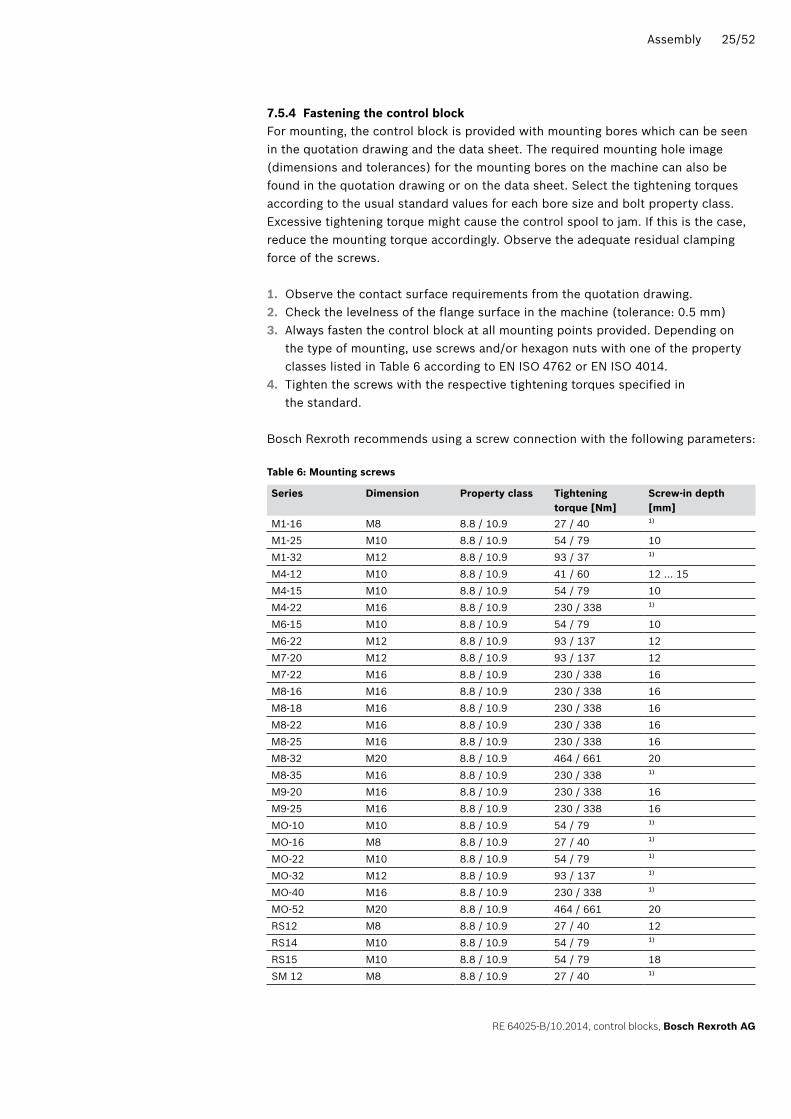
7.5.4 Fastening the control blockFor mounting, the control block is provided with mounting bores which can be seen in the quotation drawing and the data sheet. The required mounting hole image (dimensions and tolerances) for the mounting bores on the machine can also be found in the quotation drawing or on the data sheet. Select the tightening torques according to the usual standard values for each bore size and bolt property class. Excessive tightening torque might cause the control spool to jam. If this is the case, reduce the mounting torque accordingly. Observe the adequate residual clamping force of the screws.
1. Observe the contact surface requirements from the quotation drawing.2. Check the levelness of the flange surface in the machine (tolerance: 0.5 mm)3. Always fasten the control block at all mounting points provided. Depending on
the type of mounting, use screws and/or hexagon nuts with one of the property classes listed in Table 6 according to EN ISO 4762 or EN ISO 4014.
4. Tighten the screws with the respective tightening torques specified in the standard.
Bosch Rexroth recommends using a screw connection with the following parameters:
Table 6: Mounting screws
Series Dimension Property class Tightening torque [nm]
Screw-in depth [mm]
M1-16 M8 8.8 / 10.9 27 / 40 1)
M1-25 M10 8.8 / 10.9 54 / 79 10M1-32 M12 8.8 / 10.9 93 / 37 1)
M4-12 M10 8.8 / 10.9 41 / 60 12 … 15M4-15 M10 8.8 / 10.9 54 / 79 10M4-22 M16 8.8 / 10.9 230 / 338 1)
M6-15 M10 8.8 / 10.9 54 / 79 10M6-22 M12 8.8 / 10.9 93 / 137 12M7-20 M12 8.8 / 10.9 93 / 137 12M7-22 M16 8.8 / 10.9 230 / 338 16M8-16 M16 8.8 / 10.9 230 / 338 16M8-18 M16 8.8 / 10.9 230 / 338 16M8-22 M16 8.8 / 10.9 230 / 338 16M8-25 M16 8.8 / 10.9 230 / 338 16M8-32 M20 8.8 / 10.9 464 / 661 20M8-35 M16 8.8 / 10.9 230 / 338 1)
M9-20 M16 8.8 / 10.9 230 / 338 16M9-25 M16 8.8 / 10.9 230 / 338 16MO-10 M10 8.8 / 10.9 54 / 79 1)
MO-16 M8 8.8 / 10.9 27 / 40 1)
MO-22 M10 8.8 / 10.9 54 / 79 1)
MO-32 M12 8.8 / 10.9 93 / 137 1)
MO-40 M16 8.8 / 10.9 230 / 338 1)
MO-52 M20 8.8 / 10.9 464 / 661 20RS12 M8 8.8 / 10.9 27 / 40 12RS14 M10 8.8 / 10.9 54 / 79 1)
RS15 M10 8.8 / 10.9 54 / 79 18SM 12 M8 8.8 / 10.9 27 / 40 1)

26/52 Assembly
Bosch Rexroth AG, control blocks, RE 64025-B/10.2014
Series Dimension Property class Tightening torque [nm]
Screw-in depth [mm]
SP-08 M8 8.8 / 10.9 25 / 30 10 … 141)
SX 10 M8 8.8 / 10.9 27 / 40 1)
SX 12 M10 8.8 / 10.9 54 / 79 1)
SX 14 M10 8.8 / 10.9 54 / 79 1)
1) Through hole in the housing; the screw-in depth depends on the nut thread material.
7.5.5 Completing the assembly1. Remove transport aids which might have been attached.
CAUTIOn! Operation with protective plastic plugs!Operating the control block with protective plugs may cause injuries or damage to the control block.
▶ Prior to commissioning, remove all protective plugs and replace them by line connections or suitable pressure-resistant metal plug screws.
2. Remove the transport protection. The control block is delivered with protective covers and protective plugs, where appropriate. These components are not pressure-resistant and therefore have to be removed prior to connection. Use suitable tools to avoid damage to the sealing and functional surfaces. If the sealing or functional surfaces are damaged, contact your Bosch Rexroth service or the service department of the control block manufacturer.
Line connectors are equipped with protective plugs or plug screws that serve as transport protection. All connections required for the function have to be connected. Non-compliance may lead to mulfunctions or damage. Connections that are not connected have to be closed with plug screws as the protective plugs are not pressure-resistant.
7.5.6 Connecting the control block mechanicallyPlease see the quotation drawing for the connection of the actuation elements incl. tolerances. Select the tightening torques according to the actuation elements. The actuation must be free of transverse forces!
▶ Before commissioning, make sure that the tongue is in zero position (control spool in central position).

Assembly 27/52
RE 64025-B/10.2014, control blocks, Bosch Rexroth AG
7.5.7 Connecting the control block hydraulically
CAUTIOnDangerous motion of the hydraulic actuators!Risk of injury caused by incorrect pin assignment or mixed up cable connectors due to unintended actuator movement!
▶ Make sure that all pipes and/or hoses are connected to the correct control block port and do not mix them up in any case.
▶ After completion of the connections, check the correct assignment of the cable connectors to each control block solenoid.
NOTICEDamage caused by incorrect assembly!During operation, hydraulic lines and hoses installed under mechanical stress create additional mechanical forces. This reduces the life cycle of the control block and the complete machine.
▶ Assemble lines and hoses without stress.
The machine manufacturer is responsible for the design of the lines. The control block has to be connected to the remaining hydraulic system according to the hydraulic circuit diagram of the machine manufacturer.The connections and the mounting threads are designed for the peak pressure indicated in the data sheet. The machine manufacturer has to make sure that the connection elements and lines comply with the intended application conditions (pressure, flow, hydraulic fluid, temperature) including the required safety factors.
Only connect hydraulic lines that match the control block connection (pressure level, size, system of units).
Observe the following instructions regarding the installation of hydraulic lines. • Lines and hoses have to be installed without preload so that there are no additional mechanical forces during operation that reduce the life cycle of the control block and possibly the entire machine.
• If necessary, remove any resinification caused by incorrect storage. • Use suitable seals as sealants.
– Observe the compatibility of seals with the hydraulic fluid used. – Use the provided seal at each hydraulic connection. – Make sure that the connections are clean and intact.
• Make sure that the connections and connection elements are air-tight. • Pressure lines
– Only use pipes, hoses and connection elements as pressure lines that are rated for the operating pressure range indicated in the data sheet. They also have to be pressure-resistant with respect to the external air pressure.
• Tank line – Always install tank lines in such a way that the control block is always filled with hydraulic fluid and cannot drain hydraulically in case of an extended standstill.
Instructions on the installation of lines

28/52 Assembly
Bosch Rexroth AG, control blocks, RE 64025-B/10.2014
The control blocks are used in fields of application with metric and US system of units.Both the system of units and the size of the threaded hole and the screw-in stud (e.g. plug screw) must match.Due to little visual differences, there is a risk of confusion. In this regard, observe the specifications in the quotation drawing. The SI units usually apply, unless stated otherwise.
wARnInG! Leaking or ejected screw-in studs!If a screw-in stud whose system of units and size do not match the threaded hole is pressurized, it may come loose and even be ejected with high speed from the hole. This may cause serious injuries and damage to property. Hydraulic fluid may escape from this leakage point.
▶ Use the drawings (quotation drawing) to check the required screw-in stud for all fittings.
▶ Make sure that there is no confusion when installing fittings, mounting screws and plug screws.
▶ Use a screw-in stud with the same system of units and the right size for the respective threaded hole.
For an overview of the line connections, see the respective data sheet and the quotation drawing.
Observe the specifications in standards and/or the manufacturer's specifications for the screw-in studs, fittings, armatures, plug screws, etc. used. In addition, keep in mind that tightening torques may also depend on the admissible pressure and temperature range and on the application conditions.
Connecting the control block to the hydraulic system:1. Remove the protective plugs and/or plug screws from the connections that are to
be connected according to the hydraulic circuit diagram.2. Make sure that the sealing surfaces of the hydraulic connections and functional
surfaces are not damaged.3. Only use clean hydraulic lines or rinse them prior to installation. 4. Connect the lines according to the quotation drawing and the machine diagram.
Check if all connections are piped or closed with plug screws.5. Correctly tighten the fittings (observe the tightening torques!). Mark all correctly
tightened fittings, e.g. with a permanent marker.6. Check all pipes and hose lines and all combinations of connection pieces,
couplings or connection points with hoses or pipes for their operational safety.
Risk of confusion with threaded connections
Connection overview
Tightening torques
Procedure

Assembly 29/52
RE 64025-B/10.2014, control blocks, Bosch Rexroth AG
7.5.8 Connecting the control block electrically
NOTICEFunctional impairment caused by wrong plug-in connections!Only the plug-in connections listed in the data sheet/quotation drawing may be used for the electrical connection.
▶ Comply with the assembly instructions of the plug-in connection manufacturer. ▶ Before commissioning, check the power supply as to whether the voltage
complies with the details of the quotation drawing and whether the total of the currents to be expected is less than or equal to the capacity of the power supply.
▶ The plug-in connections may only be contacted when deenergized. The assembly process must not be repeated more than 10 times.
The machine manufacturer is responsible for the design of the electric control.Electrically controlled control blocks have to be connected according to the electric circuit diagram of the machine.Regarding control blocks with electric adjustment device and/or attached sensors, observe the specifications in the data sheet and the quotation drawing, e.g.: • The admissible voltage range • The admissible current • The correct pin assignment
For details on the correct connection assignment, the connector, the protection class and the matching mating connector, see the data sheet and the quotation drawing. The mating connector is not included in the scope of delivery.
Connecting the control block to the machine electronics:1. De-energize the plug-in connections of the control block.2. Prior to connection, check that the connector and all its seals are intact.3. Connect the control block to the electrical system (12 V or 24 V).
If required, change the position of the connector by turning the solenoid body (coil). This does not depend on the connector model.Proceed as follows:1. Loosen the mounting nut (1) of the solenoid using a suitable tool. For this
purpose, turn the mounting nut (1) by one turn in counterclockwise direction.2. Turn the body of the solenoid (2) in the desired position.3. Re-tighten the mounting nut with a tightening torque of 4+1 Nm.
Procedure
Changing the connector position
1
2

30/52 Commissioning
Bosch Rexroth AG, control blocks, RE 64025-B/10.2014
8 Commissioning
wARnInGDanger due to working in the danger zone of a machine!Danger to life, risk of injury or severe injury!
▶ Pay attention to potential sources of danger and remove them before commissioning the control block.
▶ When commissioning, comply with the instructions of the machine manufacturer.
CAUTIOnCommissioning an incorrectly installed product!Confusing the connections or cable connectors causes unexpected functions and/or irreparable damage to the control block and thereby endangers persons and equipment!
▶ Make sure that all electrical and hydraulic connections are either connected correctly or closed.
▶ Prior to the functional test, check if the required piping was installed according to the hydraulic circuit diagram.
▶ Check that the cable connectors are correctly assigned to the respective electric components.
▶ Commission the product only if it is installed completely.
Risk of injury caused by entrapped airAir entrapped in the control block might cause components to vibrate during operation in such a way that they hit the end stops hard and are damaged. Unexpected movements of the actuators may cause injuries.
▶ Before commissioning, make sure that entrapped air is completely removed from the control block. This can e.g. be done by a small amount of hydraulic fluid q ≤ 20 % qpump flowing through in all switching positions. If the control block is not equipped with a self-bleeding function at the covers, it may be necessary to bleed the covers by means of the bleed screw.
▶ In any case, observe the instructions on bleeding in the operating instructions of the machine.
NOTICEProduct damage and impaired functionality resulting from a lack of hydraulic fluid!Commissioning the control block without or too little hydraulic fluid will damage or even destroy the control block immediately.
▶ When commissioning or re-commissioning a machine, you should ensure that the housing area, as well as the suction and working lines of the control block are filled with hydraulic fluid and that they remain filled during operation.

Commissioning 31/52
RE 64025-B/10.2014, control blocks, Bosch Rexroth AG
8.1 Before first commissioning ▶ Make sure that the interfaces of the machine as well as the installation conditions
allow for the safe operation of the Rexroth control block. In case of doubt, please contact Bosch Rexroth.
▶ Check the operating instructions for the machine to find out in which machine the Rexroth control block must be installed and carry out a visual inspection to check whether commissioning of the hydraulics might result in uncontrolled and dangerous motions. If necessary, also observe the hazard analysis/risk assessment of the machine.
▶ Take respective precautions if risks are to be expected, e.g. make sure that the cylinder piston rod can be extended without any risk.
▶ Secure the load to be lifted additionally with a lifting tool/load lifting device. ▶ Check whether the electrical control of the machine allows for manual switching
of the control block solenoids during commissioning. If manual switching is not possible or only under difficult conditions, you must prepare an external control for the internal functional test of the hydraulic system.
▶ Develop a sequence program for the commissioning process and file it in the technical documents as annex to the operating instructions.
▶ Divide the functional circuit diagram in sub-circuits which can be commissioned one after the other.
▶ Read the functional circuit diagram and clarify ambiguous facts and representations.
▶ Determine in which spool position the control blocks must be switched and how the control blocks must be adjusted.
▶ Apply important mandatory signs, prohibition signs, information signs and check whether the meaning of these signs is explained in the operating instructions.
▶ Observe the following order for commissioning: – Pump circuit – Parts of the control: e.g. pressure cut-off and switch-over, free circulation, pressure reduction, etc.
▶ Make sure that pipes and/or hoses are connected to all ports and/or that the ports are closed with plug screws.
▶ Ensure that the cap nuts and flanges on pipe fittings and flanges are tightened according to the standard.
▶ Switch pressure and flow control valves, pump controls, and sensors such as pressure switches, position switches and thermostats to the switching positions and settings specified in the sequence program.

32/52 Commissioning
Bosch Rexroth AG, control blocks, RE 64025-B/10.2014
8.2 First commissioningFor Bosch Rexroth, the first commissioning is the first examination and release of the product.We recommend accepting points 1 up to and including 7 for the series production of the hydraulic system.
For all commissioning works on the control block observe the general safety instructions and the intended use in chapter 2 "Safety instructions" on page 9.
▶ Let the control block acclimatize itself for several hours before commissioning, as otherwise water may condense in the housing.
▶ Make sure that all electrical and hydraulic connections are either used or closed. Commission the control block only if it is completely installed.
▶ Avoid temperature shocks. There must not be temperature differences of more than 20 °C between the control block and the hydraulic fluid. Otherwise, there is a risk of jammed spools. At temperatures below –20 °C, the control block has to be warmed up.
▶ Only use hydraulic fluid that complies with the following requirements: For information on admissible hydraulic fluids, refer to the relevant data sheet of the product, see Table 1 "Required and amending documentation" on page 5.
For first commissioning of the control block, proceed as follows:1. Completely fill the control block and, if available, the pilot control circuit, with
admissible hydraulic fluid (see data sheet).2. Ensure the hydraulic supply of the control block.3. If available, ensure the power supply of the control block.4. Check the electrical connections of the control block.
Electrical connections must be checked for their proper condition by or under the guidance and supervision of a specialized electrician before first commissioning or any re-commissioning.
Observe the operating instructions of the machine where the control block is installed.

Commissioning 33/52
RE 64025-B/10.2014, control blocks, Bosch Rexroth AG
5. Bleeding the control block. – Before the actual operation, you must switch the control block several times under operating pressure in each direction of actuation and with reduced velocity. This will expel any remaining air from the control block. Mechanical damage due to inadmissibly high acceleration of the hydraulic fluid and the control spool is thus avoided and the control block's life cycle is increased. – If automatic bleeding of the cover is not sufficient, bleeding can also be carried out by means of the bleed screws potentially available at the cover (series specific). Procedure: ATTEnTIOn! When loosening the bleed screw, hydraulic fluid may leak!
▶Loosen the bleed screw of the cover by up to two rotations to ensure that the air can escape through the thread and the seal of the bleed screw. ▶Switch the valve several times in order to completely bleed the cover. ▶Fastening the bleed screw considering the valid tightening torque.
– Also observe the instructions on bleeding in the operating instructions of the machine.
Carry out a leak test.Ensure that no hydraulic fluid leaks at the control block and at the connections during operation. If hydraulic fluid leaks, see Table 8 "Fault table" on page 44.
6. Carry out a functional test. The functional test must be made according to the specifications of the machine manufacturer, see operating instructions of the machine. In any case: Slowly increase the pressure and stop the functional test immediately in case of leakage!
7. Check the hydraulic fluid temperature of the control block after several hours of continuous operation. Check whether the measured temperature lies within the product-specific limits. If the temperature lies outside the determined limits, the Bosch Rexroth warranty will forfeit.
8. Have a hydraulic fluid sample analytically tested for the required cleanliness class after initial commissioning. Replace the hydraulic fluid if the required cleanliness class is not achieved. If the hydraulic fluid is not tested in the laboratory after initial commissioning, the following applies: Replace the hydraulic fluid.
8.3 Re-commissioning after standstillRe-commissioning is necessary if the control block has been out of operation for a period of more than 12 months.
▶ Carry out the re-commissioning as described in chapter 8.2 "First commissioning" on page 32.
Also observe the instructions for (re-)commissioning after standstill in the machine operating instructions.

34/52 Operation
Bosch Rexroth AG, control blocks, RE 64025-B/10.2014
9 OperationThe product is a component which does not require any settings or modifications during operation. As a result, this chapter of the instructions does not contain any information on adjustment options. Only use the product within the performance range provided in the technical data. The machine manufacturer is responsible for the correct project planning of the hydraulic system and its control.
▶ Avoid temperature shocks. There must not be temperature differences of more than 20 °C between the control block and the hydraulic fluid. Otherwise, there is a risk of jammed spools. With temperatures below –20 °C, the control block has to be warmed up.
9.1 Information on the use of control blocks at low temperatures • Minimum ambient temperature –40 °C • Warm-up phase with little load from –40 °C • Operation with load from –25 °C
• For use under –25 °C, seals deviating from the standard are used. Differing limits of use are specified in the Technical Customer Documents (TKU) of the control block.
• Avoid humidity in the environment of the control blocks as potential condensation at the movement seals may lead to freezing of the control spools during standstill. This may also lead to the destruction of the seal ring if the control spool is actuated.
• The viscosity limits specified in the control blocks data sheets must be complied with over the entire operating period by selecting a suitable hydraulic fluid, both in winter and in summer with warmer temperatures.
• For boundary conditions, the following values apply: νmin = 5 mm²/s
(shortly at a max. admissible temperature of θmax = 115 °C/90 °C) Note that the max. hydraulic fluid temperature of 115 °C (90 °C for perbunan) must not be exceeded locally, e.g. at the pressure reducing valve, either.
νmax = 2000 mm²/s
(shortly in case of cold start, n ≤ 1000 min-1, θmin = –40 °C)
• Especially the start-up viscosity must be observed. • If new components are installed into a cold machine, they must be filled at higher temperatures in advance to ensure sufficient lubrication in all areas.
• Coordinate the measures for filters, cylinders, gears etc. with the manufacturers.
Boundary conditions
General information

Operation 35/52
RE 64025-B/10.2014, control blocks, Bosch Rexroth AG
• Control units, amplifiers, sensors, encoders, solenoids – Minimum storage temperature –50 °C – Installation and full function from –40 °C
• Devices with displays (unless specified in more detail) – Minimum storage temperature –20 °C – Installation and full function from –20 °C
• With switching and proportional solenoids, possible increases in the hysteresis and/or extended switching times due to increasing operating medium viscosity with decreasing temperature are to be expected.
1. Heat up all components to at least –40 °C.2. Start the drive motor.3. Warm up the pump according to the specification (see data sheet 90300-03-B)4. Warm-up phase of the open hydraulic system
– Pump starts up with Diesel motor and should be operated with idle speed of the Diesel motor for at least 10 minutes in order to ensure self lubrication. – The pump must be in pressure-reduced circulation (max. 50 bar and max. 50 % delivery volume). – Loading of the open circuit, e.g. by means of separate preload valve, generates a circulation pressure of approx. 50 bar at the pump. Maintain this operating state until –25 °C are reached in the system. The Diesel speed must not be increased. – Afterwards, operate all machine functions slowly and several times at minimum load in order to heat up the entire machine as evenly as possible. In this connection, the tank temperature is to be observed which will decrease again due to the return flow of the cold hydraulic fluid.
5. Warm-up phase of the closed hydraulic system – Set the pump to neutral position without flow. – The pump starts up with Diesel motor and should be operated with idle speed of the Diesel motor for at least 10 minutes. – Afterwards, slowly swivel out the pump. All machine functions must be operated slowly and several times without load until –25 °C are reached in the entire machine.
6. Valves that are used at low temperature enable flushing from the pump to the tank in order to sufficiently heat the control block.
7. The covers in hydraulically pilot operated valves are flushed with tank oil via the flushing channels.
8. After completed pump warm-up, slowly operate all actuators without load in order to exchange the cold oil contained in the actuators by warm oil.
9. The flushing should remain functional during operation in order to keep actuators which are only operated occasionally at operating temperature.
10. Permanent flushing is necessary in all components in order to avoid temperature shocks. The max. admissible temperature difference between operating medium and the individual components is 20 °C.
11. Our control blocks may be loaded from a circuit temperature of ≥ –25 °C in the machine.
Information on the electronics
Procedure

36/52 Maintenance and repair
Bosch Rexroth AG, control blocks, RE 64025-B/10.2014
10 Maintenance and repair
CAUTIOnRisks caused by reduced safety during maintenance worksExperience has shown that the number of accidents during maintenance is higher than during normal operation. Therefore, we would ask you to observe the following safety instructions in the interest of your safety.
▶ Regularly check the safety equipment – if any – for correct functionality. ▶ Complete all maintenance in due time, properly and completely and document it. ▶ Adequately secure the maintenance area before starting maintenance. ▶ Pay attention to cleanliness in order to avoid malfunctions caused by pollution.
Paint residues on sealing surfaces must be removed before assembly. Make sure that paint residues do not enter control block openings as this may lead to malfunctions.
▶ Operate the hydraulic product in maintenance mode with increased alertness as it may possibly require disassembly of certain protective devices. Switch off the hydraulic product and secure it against unintended re-activation.
▶ The user is not allowed to change the settings of safety valves. Re-adjustments may only be carried out by authorized testing authorities.
▶ Wear protective goggles, protective gloves and safety boots. Depressurize the hydraulic product and properly unload available pressure accumulators, if applicable.
▶ Let system sections and pressure lines which can be opened cool down before starting maintenance.
▶ Open slowly any segments that are still pressurized. ▶ Please observe that the hydraulic system might still be pressurized even after
it has been disconnected from the actual pressure supply if there are check valves in the pressure lines above the pumps. Move all cylinders to the safe end position.
▶ Lower all loads. Provide for an external safeguard if the load cannot be lowered. Maintenance must not be carried out at lifted units without external safeguard.
▶ Switch off all pumps. ▶ Support vertical cylinders mechanically against sinking. ▶ Only new, structurally identical and tested components, spare parts and
lubricants in original equipment quality are admitted for replacement/use. ▶ Make sure that all protective devices and especially all protective functions
which could impair the safety-shutdown strategy are correctly installed and checked for functionality before re-commissioning.
▶ After the completion of all work, remove all tools and devices used for maintenance from the hydraulic product.
Personal injury caused by non-functional spare partsSpare parts that do not meet the technical requirements specified by Bosch Rexroth may cause personal injuries.
▶ Only use original Rexroth spare parts.

Maintenance and repair 37/52
RE 64025-B/10.2014, control blocks, Bosch Rexroth AG
NOTICEPenetrating dirt and fluids will cause malfunctions!Safe function of the control block is no longer ensured.
▶ Always ensure absolute cleanliness when working at the control block. ▶ Cover all openings with appropriate protective equipment in order to prevent
cleaning agents from penetrating the system. ▶ Ensure that all seals and caps of the plug-in connections are firmly attached so
that no humidity can penetrate the control block during cleaning. ▶ Dust accumulation on the control block has to be removed at regular intervals.
Damage to the surface from solvents and aggressive cleaning agents!Aggressive cleaning agents may damage the seals of the control block and accelerate ageing.
▶ Never use solvents or aggressive cleaning agents (cleaning agents on a solvent base).
▶ Only clean the control block using a damp, lint-free cloth. Only use water and, if necessary, a mild cleaning agent.
Damage to the hydraulic system and seals!The water pressure of a high-pressure washer may damage the hydraulic system and the seals of the control block. The water displaces the oil from the hydraulic system and seals.
▶ Do not use high-pressure washers for cleaning.
Delayed inspections and maintenance works!Damage to property!
▶ Perform the prescribed inspection and maintenance works at the control block at the intervals specified in these instructions.
Also observe the instructions for maintenance and repair in the machine operating instructions.

38/52 Maintenance and repair
Bosch Rexroth AG, control blocks, RE 64025-B/10.2014
10.1 InspectionFor reliable operation of the control block, Bosch Rexroth recommends checking the control block on a regular basis and recording and archiving the following operating conditions:
Table 7: Inspection plan
works to be carried out at the control block Interval
Check the operating temperature weekly
Hydraulic fluid analysis: Viscosity, time deterioration and contamination
annually or all 2000 operating hours
Check the control block for external leakage (visual inspection). daily
Check the control block for the development of strange noises. daily
Check the mounting elements for tight seat. All mounting elements have to be checked when the control block is depressurized, de-energized and cool.
monthly
10.2 MaintenanceIf used as intended, the control block is low-maintenance.The life cycle of control block decisively depends on the quality of the applied hydraulic fluid. We therefore recommend exchanging the hydraulic fluid at least once per year or every 2000 operating hours (whichever occurs first) or to have it analyzed for further usability by the hydraulic fluid manufacturer or a laboratory.
Observe the following general rule: From a hydraulic fluid temperature of > 70 °C, the aging speed doubles with every 10 °C temperature increase. For the maximum admissible degree of contamination of the hydraulic fluid, see the data sheet in chapter "Technical data". Also observe the information on the hydraulic fluid in the operating instructions of the machine.
10.3 RepairBosch Rexroth offers a wide range of repair services for Rexroth control blocks.The control block may only be repaired by Bosch Rexroth certified service centers or by the machine manufacturer.
▶ Exclusively use Rexroth original spare parts to repair the Rexroth control blocks. Otherwise, the functional safety of the control block is no longer ensured and you lose your claim to warranty.
For questions regarding repair, contact your local Bosch Rexroth service or the service department of the control block manufacturer's factory, see chapter 10.4 "Spare parts" on page 39.
For repair works, the control block may only be disassembled to the extent described in these operating instructions.

Maintenance and repair 39/52
RE 64025-B/10.2014, control blocks, Bosch Rexroth AG
10.4 Spare parts
CAUTIOnUse of unsuitable spare parts!Spare parts that do not meet the technical requirements specified by Bosch Rexroth may cause personal injuries and damage to property.
▶ Exclusively use Rexroth original spare parts to repair the Rexroth control blocks. Otherwise, the function of the control block is no longer ensured and you lose your claim to warranty.
Spare parts lists are available from your local Bosch Rexroth representative.Indicate the material and serial numbers of the control block as well as the material numbers of the spare parts when ordering spare parts.In case of questions regarding spare parts, please contact your local Bosch Rexroth service or the service department of the control block manufacturer's factory.
Bosch Rexroth AG Zum Eisengießer 1 97816 Lohr am Main, Germany Phone: +49 (0) 9352 18-40 50 60 [email protected]
For the addresses of our sales and service network, see www.boschrexroth.de/adressen.
40/52 Disassembly and exchange
Bosch Rexroth AG, control blocks, RE 64025-B/10.2014
11 Disassembly and exchange
11.1 necessary tools • Tools suitable for the fastenings specified in the quotation drawing • Permanent marker for marking the control block plates • Clean collecting pan for collecting leaking hydraulic fluid
11.2 Preparing disassembly1. Decommission the overall system as described in the machine
operating instructions. – Depressurize and unload the hydraulic system as described by the machine manufacturer. – Ensure that the control block is depressurized and de-energized.
2. Secure the overall system according to the manufacturer's instructions.
11.3 Disassembling the control block from the machine
If the component to be exchanged (e.g. screw-in cartridge valve) is freely accessible from the outside, the control block does not have to be disassembled from the machine.
Proceed as follows to disassemble the control block:1. Let the control block cool down so that it can be disassembled without risks.2. Make sure that no hydraulic fluid can escape unintentionally from the system due
to the disassembly of the control block.3. Place a clean collecting pan below the control block to collect any escaping
hydraulic fluid residues.4. Disconnect the lines and collect any escaping hydraulic fluid residues in the
collecting pan.5. Disassemble the control block according to the machine
manufacturer’s specifications. 6. Place the product on a clean, bearing surface.7. Drain the control block completely.8. Close all openings in order to prevent the deposition of dirt.
11.4 Preparing the components for storage/further use ▶ Proceed as described in chapter 6.2 "Storing the control block", section "After
disassembly" on page 22.

Disposal 41/52
RE 64025-B/10.2014, control blocks, Bosch Rexroth AG
12 Disposal
CAUTIOnSpring preloaded components!Risk of injury due to ejected components when the valve is disassembled into its individual components!
▶ Slowly loosen screw-in parts and spring preloaded components and secure them until the compression spring is unloaded.
Careless disposal of the control block, the hydraulic fluid and the packaging material may lead to environmental pollution.For the disposal of the control block, comply with the following instructions:1. Drain the control block completely.2. Dispose of the control block and the packaging material in accordance with the
applicable national regulations in your country.3. Dispose of the hydraulic fluid in accordance with the currently applicable national
regulations in your country. 4. Disassemble the control block into its individual components in order to
recycle them.5. Separate for example:
– Steel – Aluminum – Non-ferrous metal – Electrical and electronic parts (solenoids, sensors, coils) – Plastic – Rubber (seals, bellows, pedal rubber)

42/52 Extension and modification
Bosch Rexroth AG, control blocks, RE 64025-B/10.2014
13 Extension and modificationModifications as well as changes in settings at the control block are not admissible.
The Bosch Rexroth warranty applies only to the configuration supplied. Following an extension or a modification, the claim to warranty expires.
Adjusting the settings causes the claim to warranty to expire. If you require the settings to be changed, contact your local Bosch Rexroth service, for the address see chapter 10.4 "Spare parts" on page 39.
For available accessories, see the respective data sheet.Accessories are available from your Rexroth specialist dealer. For addresses of our sales and service network, see www.boschrexroth.de/adressen.
Optional accessories

Troubleshooting 43/52
RE 64025-B/10.2014, control blocks, Bosch Rexroth AG
14 TroubleshootingUse Table 8 for troubleshooting. This table is not exhaustive.In practice, there may be problems that are not included here.
14.1 How to proceed for troubleshooting ▶ Work systematically and in a targeted way. ▶ First, get a general idea of how your product works in conjunction with the
overall system. ▶ Try to find out whether the product has worked properly in conjunction with the
overall system before the error occurred. ▶ Try to determine any changes at the overall system into which the product
is integrated: – Have the product’s operating conditions or its area of application been changed? – Was any maintenance work performed? Is there an inspection or maintenance record? – Have modifications (e.g. refittings) or repairs works been done on the overall system (machine, electrics, control) or on the product? – Has the hydraulic fluid been changed? – Has the product or machine been used as intended? – How did the fault become apparent?
▶ Try to get a clear idea of the cause of the error. If necessary, ask the actual (machine) operator.
▶ Document all work done. ▶ If you could not remedy the occurred error, please contact one of the
addresses you find at http://www.boschrexroth.com/adressen or in chapter 10.4 "Spare parts".

44/52 Troubleshooting
Bosch Rexroth AG, control blocks, RE 64025-B/10.2014
14.2 Fault tableThe control block is not sensitive to faults if the specified application conditions are met. This particularly applies to the quality of the hydraulic fluid and the maximum admissible pressure values.
Table 8: Fault table Fault Possible causes RemedyHydraulic fluid leaks at the control block and/or the control block plates
Control block is leaking Tighten the mounting screws applying the specified tightening torque.
Plug screws are leaking Tighten the plug screws applying the specified tightening torque; replace copper seal rings, if necessary. For O-ring seals: Do not tighten up plug screw, replace seals and tighten plug screw with specified tightening torque.If leakage persists:Check sealing surfaces/seal for damage. Where appropriate, replace the plug screw.
Control block housing and/or control block plate is leaking
Disassemble the control block and/or the control block plate and replace by a new one.
Connections leading to the actuator (screw necks, fittings) are leaking
Check seals and replace the fittings, if necessary. Check tightening torques, see details of thefitting manufacturer.
Valve housing at the secondary valve/plug screw is leaking
Replace secondary valve/plug screw.
Hydraulic fluid leaks from the supply lines to the control block
Piping or hose lines damaged
The piping or hose lines are loose
Replace piping or hose lines.
Tighten screwing and fittings according to the assembly instructions applicable for fittings. All assembly instructions are available from the machine manufacturer.
Hydraulic fluid escapes between the control block plates
Seals in the flange surface are damaged Replace seals, see "Installation drawing".Deposition of dirt during assembly of the control block
Disassemble control block, clean flange surface.
Control block housing leaking at the flange surface
Replace control block plate.
Tightening torque of the tie rods too low Check tightening torques, see "Technical data sheet".Residual oil from assembly/test of the control block
Remove oil and dirt from the control block. Do not use any cleaning agents which are aggressive against plastic or metal, change the properties of plastic, react with metal or generate residues.
Working movement not constant
There is air in the hydraulic fluid Bleed the hydraulic system, see page 33.
Version: Mechanical actuation:The control spool cannot be controlled mechanically
Tie rod screwed with too much/different tightening torque
Loosen tie rod nuts and tighten with specified tightening torque.
Oil temperature too high and/or temperature difference between hydraulic fluid and control block too high, thus blocking of control spool and control block as a result of different thermal expansion
Check cooler function, oil supply and pump pressure in neutral position. Avoid temperature shock, for related information see "Technical data sheet".
Dirt or foreign matter deposited during the assembly of the connectors leading to the actuator jam the control spool
Try several times to switch the valve by actuating the hand lever and/or the pilot control.Visually check the connections to the actuator, remove foreign matter using a solenoid or tweezers. Replace valve housing in case of jammed foreign matter.
The control spool does not reset or resets too slowly.
The control spool jams See fault above "Control spool cannot be controlled mechanically".
Control spool is retained due to the flow force which is caused by too much oil flow
Reduce oil flow from the actuator to the tank.

Troubleshooting 45/52
RE 64025-B/10.2014, control blocks, Bosch Rexroth AG
Table 8: Fault table Fault Possible causes RemedyVersion: Electro-hydraulic actuationControl spool shows no reaction or delayed reaction to electric control
No solenoid current or solenoid current too low, wrong operating point (solenoid current not correctly adjusted to oil flow)
Check voltage supply and operating point Q/I, see "Technical data sheet". Check plug-in connections.
Pilot control valve and/or solenoid valve does not work
Replace pilot control valve and/or solenoid valve.
Undersupply (pump pressure too low). Provide minimum pump pressure, see "Technical data sheet".
Undersupply (pump pressure too low). Provide minimum pump pressure, see "Technical data sheet".
Pilot oil supply jams Disassemble pilot oil supply and replace by a new one.Pilot control valves are contaminated Replace pilot control valve.
Version: Hydraulic actuation
Undersupply (pump pressure too low) Provide minimum pump pressure, see "Technical data sheet".
No pilot pressure Check pilot oil supplyFor valves in parallel operation: No pressure and/or no oil flow at the actuator with deflected control spool, considerably delayed pressure build-up
Oil flows to the actuator with minimum pressure due to undersupply
Increase pump oil flow by applying higher speed or larger pump, and/or reduce actuator volume using a volume throttle.
Neutral circulation pressure too high
No load-sensing unloading (only for M4, M6, M7, SP,SX)Control spool not in neutral position For tongue: Check projection, see "Technical data sheet".
Pressure in the control covers too high (check control).Return flow pressure too high Separate return flow from mutual return line, use
separate return line or increase line cross-section.Inlet pressure compensator jams Replace inlet plate.
Motion at the actuator despite neutral position
Control spool not in neutral position Pressure in the control covers too high (check control).Secondary pressure relief valve is leaking and/or set too low
Check set pressure at the secondary pressure relief valve.
Leakage at control spool too large Leakage values see data sheet.Install leakage-free lowering brake valve.
No detent function Return force in the actuating element too high compared to the detent force (spring)
Disassemble and clean the detent.
Detent unit worn out Replace the detent unit.Detent release force too high
The control spool jams See "Control spool cannot be deflected" under "Control spool is jammed" at the top of this table.
Detent unit damaged Replace the detent unit.Detent force too high Clean and grease detent unit. Replace detent unit if
malfunction cannot be removed.
Following faults due to contamination, it is – in addition to the repair – essential to check the quality of the hydraulic fluid and to improve it, if necessary, by suitable measures such as flushing, replacement or the additional installation of filters.

46/52 Technical data
Bosch Rexroth AG, control blocks, RE 64025-B/10.2014
15 Technical dataFor the admissible technical data of the control blocks, see the respective data sheet. The assignment of the control blocks to the data sheets is available in Table 1 "Required and amending documentation" on page 5.
The data sheets are available on the Internet atwww.boschrexroth.com/various/utilities/mediadirectory
For further information, refer to the online product catalogMobile hydraulics: www.boschrexroth.de/mobilhydraulik-katalog
The order-specific technical data of your control block are available in the order confirmation.

Technical data 47/52
RE 64025-B/10.2014, control blocks, Bosch Rexroth AG

48/52 Index
Bosch Rexroth AG, control blocks, RE 64025-B/10.2014
16 Index
▶ AAbbreviations 8Accessories 42Assembly 23 – Completing 26 – preparing 24
▶ BBleeding 33
▶ CCommissioning 30 – first 32
Connecting – electrical 29 – hydraulically 27
Corrosion protection 21
▶ DDesignations 8Disassembly 40 – implementing 40 – preparing 40
Disposal 41
▶ FFault table 44Functional test 33
▶ HHydraulic fluid 32 – Disposal 41 – exchange 38
▶ IIdentification 17Inspection 38Installation conditions 24Installation position 24Intended use 9
▶ llifting strap 20Lifting tool 19
▶ MMaintenance 38Modification 42
▶ nName plate 17
▶ OOperation 34
▶ PPerformance description 17Product description 17
▶ QQualification of personnel 10
▶ RRe-commissioning – after standstill 33
Repair 38Required documentation 5
▶ SSafety instructions 9 – General 10 – Product-specific 11 – Signal word 7
Scope of delivery 16Settings 42Solenoid position – change 29
Spare parts 39Storage time 21Storing 21Symbols 8

Index 49/52
RE 64025-B/10.2014, control blocks, Bosch Rexroth AG
▶ TTechnical data 46Tools 24, 40Transport 19 – by hand 19 – using a lifting strap 20 – using lifting tools 19
Troubleshooting 43 – Fault table 44
▶ UUnpacking 23
▶ wWarranty 14, 21, 42Weight 19

50/52 Index
Bosch Rexroth AG, control blocks, RE 64025-B/10.2014

Index 51/52
RE 64025-B/10.2014, control blocks, Bosch Rexroth AG

Bosch Rexroth AGMobile ApplicationsZum Eisengießer 197816 Lohr am MainGermanyPhone +49 9352 [email protected]
Subject to change without noticePrinted in GermanyRE 64025-B/10.2014
For your local contact, please refer to:www.boschrexroth.de/adressen