for model no. paxlt0u0 only - red lion product manual.pdf · tel +1 (717) 767-6511 fax +1 (717)...
TRANSCRIPT

5 DIGIT, 0.56" HIGH RED LED DISPLAY DISPLAYS °C OR °F WITH 1° OR 0.1° RESOLUTION BACKLIGHT OVERLAYS INCLUDED (°C AND °F) MAX AND MIN READING MEMORY TC COLD JUNCTION COMPENSATION (ON/OFF) PROGRAMMABLE TEMPERATURE OFFSET PROGRAMMABLE USER INPUT DUAL 5 AMP FORM C RELAYS UNIVERSALLY POWERED NEMA 4X/IP65 SEALED FRONT BEZEL THERMOCOUPLE AND RTD INPUTS CONFORMS TO ITS-90 STANDARDS
GENERAL DESCRIPTIONThe PAXLT is a versatile meter that accepts a variety of thermocouple and
RTD inputs and provides a temperature display in Celsius or Fahrenheit. The readout conforms to ITS-90 standards, with 1° or 0.1° resolution. The 5-digit display has 0.56" high digits with adjustable intensity. Backlight overlay labels for °F and °C are included.
The meter features a Maximum and Minimum reading memory, with programmable capture time. The capture time is used to prevent detection of false max or min readings which may occur during start-up or unusual process events. Either value can be displayed if desired. The display can be toggled manually or automatically between the selected values.
Other features include thermocouple cold junction compensation, display offset and a programmable user input to perform a variety of meter control functions. Two setpoint outputs are provided, each with a Form C relay. Output modes and setup options are fully programmable to suit a variety of control requirements.
The PAXLT can be universally powered from a wide range of AC or DC voltage. The meter has been specifically designed for harsh industrial environments. With a NEMA 4X/IP65 sealed bezel and extensive testing to meet CE requirements, the meter provides a tough yet reliable application solution.
SAFETY SUMMARYAll safety regulations, local codes and instructions that appear in this and
corresponding literature, or on equipment, must be observed to ensure personal safety and to prevent damage to either the instrument or equipment connected to it. If equipment is used in a manner not specified by the manufacturer, the protection provided by the equipment may be impaired.
Do not use this meter to directly command motors, valves, or other actuators not equipped with safeguards. To do so can be potentially harmful to persons or equipment in the event of a fault to the meter
SPECIFICATIONS1. DISPLAY: 5 digit, 0.56" (14.2 mm) intensity adjustable Red LED2. POWER REQUIREMENTS:
AC POWER: 50 to 250 VAC 50/60 Hz, 12 VAIsolation: 2300 Vrms for 1 min. to all inputs and outputsDC POWER: 21.6 to 250 VDC, 6 W
3. READOUT:Display Range: -19999 to 99999Scale: °F or °CResolution: 1° or 0.1°Response Time: 500 msec min.Display Overrange/Underrange Indication: "….." / "-…."Input Overrange/Underrange Indication: /
1
3.60 (91.4)(96.5)3.80
1.95(49.5)
(2.5).10
(104.1)4.10
(44.5)1.75
PAR91 32 4 5 6 7 8 10 1311 12 14 15
SEL RST
SP1 SP2
8.8.8.8.8XMAIMN
MODEL PAXLT - PAX LITE TEMPERATURE METER
DIMENSIONS In inches (mm)
Bulletin No. PAXLT-A
Drawing No. LP0750
Released 04/13
Tel +1 (717) 767-6511
Fax +1 (717) 764-0839
www.redlion.net
CAUTION: Risk of Danger.Read complete instructions prior to
installation and operation of the unit.
CAUTION: Risk of electric shock.
ORDERING INFORMATIONMODEL NO. DESCRIPTION PART NUMBER
PAXLT0U0
PAXLT000
PAXLT
Note: Recommended minimum clearance (behind the panel) for mounting clip installation is 2.1" (53.4) H x 5.0" (127) W.
TC/RTD Temperature Meter with Dual Relay Output
C US LISTEDULR
51EBIND. CONT. EQ.
For Model No. PAXLT0U0 Only
UL Listed TC/RTD Temperature Meter with Dual Relay Output

2
4. THERMOCOUPLE INPUTS:Input Impedance: 20 MΩMax. Continuous Overvoltage: 30 VDCFailed Sensor Indication:
*After 20 min. warm-up. Accuracy is specified in two ways: Accuracy at 23°C and 15 to 75% RH environment; and Accuracy over a 0 to 50 °C and 0 to 85% RH (non condensing) environment. Accuracy specified over the 0 to 50 °C operating range includes meter tempco and cold junction tracking effects.
The specification includes the A/D conversion errors, linearization conformity, and thermocouple cold junction compensation. Total system accuracy is the sum of meter and probe errors. Accuracy may be improved by field calibrating the meter readout at the temperature of interest.
5. RTD INPUTS:Type: 2, 3 or 4 wireExcitation Current:
100 ohm range: 165 µA; 10 ohm range: 2.5 mALead Resistance:
100 ohm range: 10 Ω/lead max.; 10 ohm range: 3 Ω/lead max.Balanced Lead Resistance: Automatically compensated up to max per leadUnbalanced Lead Resistance: Uncompensated
Max. Continuous Overvoltage: 30 VDCFailed Sensor Indication: or
*After 20 min. warm-up. Accuracy is specified in two ways: Accuracy at 23°C and 15 to 75% RH environment; and Accuracy over a 0 to 50°C and 0 to 85% RH (non condensing) environment. Accuracy specified over the 0 to 50°C operating range includes meter tempco effects.
The specification includes the A/D conversion errors and linearization conformity. Total system accuracy is the sum of meter and probe errors. Accuracy may be improved by field calibrating the meter readout at the temperature of interest.
6. USER INPUT: Programmable inputSoftware selectable for active logic state: active low, pull-up (24.7 KΩ to +5
VDC) or active high, pull-down resistor (20 KΩ).Trigger levels: VIL = 1.0 V max; VIH = 2.4 V min; VMAX = 28 VDCResponse Time: 10 msec typ.; 50 msec debounce (activation and release)
7. MEMORY: Nonvolatile E2PROM retains all programming parameters and max/min values when power is removed.
8. OUTPUTS:Type: Dual Form C contactsIsolation to Sensor & User Input Commons: 1400 Vrms for 1 min.
Working Voltage: 150 VrmsContact Rating: 5 amps @ 120/240 VAC or 28 VDC (resistive load), 1/8
H.P. @ 120 VAC (inductive load)
Life Expectancy: 100 K cycles min. at full load rating. External RC snubber extends relay life for operation with inductive loads.
Response Time: Turn On or Off: 4 msec max. 9. ENVIRONMENTAL CONDITIONS:
Operating temperature: 0 to 50 °CStorage temperature: -40 to 70 °COperating and storage humidity: 0 to 85% max. RH (non-condensing)Vibration to IEC 68-2-6: Operational 5 to 150 Hz, 2 g.Shock to IEC 68-2-27: Operational 30 g (10 g relay).Altitude: Up to 2,000 meters
10. CONNECTIONS: High compression cage-clamp terminal blockWire Strip Length: 0.3" (7.5 mm)Wire Gage: 30-14 AWG copper wireTorque: 4.5 inch-lbs (0.51 N-m) max.
11. CONSTRUCTION: This unit is rated for NEMA 4X/IP65 outdoor use. IP20 Touch safe. Installation Category II, Pollution Degree 2. One piece bezel/case. Flame resistant. Synthetic rubber keypad. Panel gasket and mounting clip included.
12. CERTIFICATIONS AND COMPLIANCES:CE Approved
EN 61326-1 Immunity to Industrial LocationsEmission CISPR 11 Class AIEC/EN 61010-1RoHS Compliant
Type 4X Outdoor Enclosure rating (Face only)IP65 Enclosure rating (Face only)IP20 Enclosure rating (Rear of unit)
For Model No. PAXLT0U0 Only: UL Listed: File #E137808Refer to EMC Installation Guidelines section of the bulletin for additional
information.13. WEIGHT: 10.4 oz. (295 g)
TC TYPE RANGEACCURACY
@ 23°C ±°C *
WIRE COLOR
5.8
4.3
15.0
ANSI BS 1843
T -200 to 400°C -328 to 752°F 2.3 (+) blue
(-) red(+) white (-) blue
J -200 to 760°C -328 to 1400°F 1.9 (+) white
(-) red(+) yellow (-) blue
R -50 to 1768°C -58 to 3214°F 4.5 no
standard(+) white (-) blue
S -50 to 1768°C -58 to 3214°F 4.5 no
standard(+) white (-) blue
B 200 to 1820°C 392 to 3308°F
9.1<540°C 4.5>540°C
no standard
no standard
E -200 to 871°C -328 to 1600°F 2.7 (+) purple
(-) red(+) brown (-) blue
N -200 to 1300°C -328 to 2372°F 2.8 (+) orange
(-) red(+) orange (-) blue
K -200 to 1372°C -328 to 2502°F 2.3 (+) yellow
(-) red(+) brown (-) blue
mV
C (W5/W26)
-10.00 to 65.00
0 to 2315°C 32 to 4199°F
0.02 mV
1.9
no standard
no standard
no standard
no standard
15.0
42.6<540°C 15.0>540°C
4.9
8.1
5.8
0.08 mV
6.1
ACCURACY @ 0 to 50°C
±°C *
STANDARDACCURACY* @0 to 50°C
ACCURACY* @ 23°CRANGE
no official standard0.9°C0.4°C-100 to 260°C10 ohm Copper
alpha = .00427
RTD TYPE
no official standard0.5°C0.2°C-80 to 260°C120 ohm Nickel
alpha = .00672
no official standard1.6°C0.4°C-200 to 850°C100 ohm Pt
alpha = .00392
IEC 7511.6°C0.4°C-200 to 850°C100 ohm Pt alpha = .00385

3
3.0 Wiring the MeterWIRING OVERVIEW
Electrical connections are made via screw-clamp terminals located on the back of the meter. All conductors should conform to the meter’s voltage and current ratings. All cabling should conform to appropriate standards of good installation, local codes and regulations. It is recommended that the power supplied to the meter (DC or AC) be protected by a fuse or circuit breaker.
When wiring the meter, compare the numbers embossed on the back of the meter case against those shown in wiring drawings for proper wire position. Strip the wire, leaving approximately 0.3" (7.5 mm) bare lead exposed (stranded wires should be tinned with solder.) Insert the lead under the correct screw-clamp terminal and tighten until the wire is secure. (Pull wire to verify tightness.)
EMC INSTALLATION GUIDELINESAlthough Red Lion Controls Products are designed with a high degree of
immunity to Electromagnetic Interference (EMI), proper installation and wiring methods must be followed to ensure compatibility in each application. The type of the electrical noise, source or coupling method into a unit may be different for various installations. Cable length, routing, and shield termination are very important and can mean the difference between a successful or troublesome installation. Listed are some EMI guidelines for a successful installation in an industrial environment.1. A unit should be mounted in a metal enclosure, which is properly connected
to protective earth.2. Use shielded cables for all Signal and Control inputs. The shield connection
should be made as short as possible. The connection point for the shield depends somewhat upon the application. Listed below are the recommended methods of connecting the shield, in order of their effectiveness.
1.0 installing the Meter
2.0 setting the JuMperINPUT RANGE JUMPER (RTD ONLY)
This jumper is used to select the proper input range for the RTD probe being used (10 ohm or 100 ohm). For thermocouple inputs, this jumper has no effect and can be left in either position.
To access the jumper, remove the meter base from the case by firmly squeezing and pulling back on the side rear finger tabs. This should lower the latch below the case slot (which is located just in front of the finger tabs). It is recommended to release the latch on one side, then start on the other side latch.
MainCircuitBoard
REAR TERMINALS
FRONT DISPLAY
RTD RANGEJUMPER
10 OHM 100 OHM
Installation The PAX Lite meets NEMA 4X/IP65 requirements when properly installed.
The unit is intended to be mounted into an enclosed panel. Prepare the panel cutout to the dimensions shown. Remove the panel latch from the unit. Slide the panel gasket over the rear of the unit to the back of the bezel. The unit should be installed fully assembled. Insert the unit into the panel cutout.
While holding the unit in place, push the panel latch over the rear of the unit so that the tabs of the panel latch engage in
the slots on the case. The panel latch should be engaged in the farthest
forward slot possible. To achieve a proper seal,
tighten the latch screws evenly
until the unit is snug in the panel (Torque to approximately 7 in-lbs [79N-cm]). Do not over-tighten the screws.
Installation EnvironmentThe unit should be installed in a location that does not exceed the maximum
operating temperature and provides good air circulation. Placing the unit near devices that generate excessive heat should be avoided.
The bezel should be cleaned only with a soft cloth and neutral soap product. Do NOT use solvents. Continuous exposure to direct sunlight may accelerate the aging process of the bezel.
Do not use tools of any kind (screwdrivers, pens, pencils, etc.) to operate the keypad of the unit.
PANEL GASKET
BEZEL
PANEL MOUNTING SCREWS
LATCHING SLOTS
PANEL
LATCHING TABS
PANEL LATCH
-.00
(92 )-.0+.8
3.62 +.03
(45 )1.77
-.0+.5-.00+.02
PANEL CUT-OUT
4
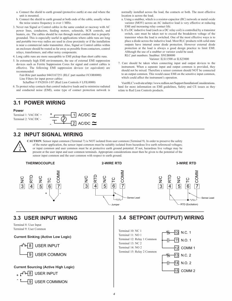
3.3 USER INPUT WIRING
CAUTION: Sensor input common (Terminal 7) is NOT isolated from user common (Terminal 9). In order to preserve the safety of the meter application, the sensor input common must be suitably isolated from hazardous live earth referenced voltages; or input common and user common must be at protective earth ground potential. If not, hazardous live voltage may be present at the user input and user common terminals. Appropriate considerations must then be given to the potential of the sensor input common and the user common with respect to earth ground.
Terminal 8: User InputTerminal 9: User Common
3.4 SETPOINT (OUTPUT) WIRING
Terminal 10: NC 1Terminal 11: NO 1Terminal 12: Relay 1 CommonTerminal 13: NC 2Terminal 14: NO 2Terminal 15: Relay 2 Common
USER INPUT8
USER COMMON9
USER INPUT
USER COMMMON9
8+
-
10 N.C. 1
COMM 112
11 N.O. 1
13
14
15
N.C. 2
N.O. 2
COMM 2
Current Sinking (Active Low Logic)
Current Sourcing (Active High Logic)
3.2 INPUT SIGNAL WIRING
3.1 POWER WIRINGPowerTerminal 1: VAC/DC +Terminal 2: VAC/DC -
1
2
AC/DC
AC/DC
+
-
~~
5+ -
CO
MM
TC
6 7
RTD
4
N/C
3
N/C
THERMOCOUPLE
Sense Lead
Jumper
RTD
4
TC
5 6
CO
MM
7
N/C
3
N/C
2-WIRE RTD
RTD (Excitation)
Sense Lead
RTD
4TC
5 6
CO
MM
7N
/C
3
N/C
3-WIRE RTD
a. Connect the shield to earth ground (protective earth) at one end where the unit is mounted.
b. Connect the shield to earth ground at both ends of the cable, usually when the noise source frequency is over 1 MHz.
3. Never run Signal or Control cables in the same conduit or raceway with AC power lines, conductors, feeding motors, solenoids, SCR controls, and heaters, etc. The cables should be run through metal conduit that is properly grounded. This is especially useful in applications where cable runs are long and portable two-way radios are used in close proximity or if the installation is near a commercial radio transmitter. Also, Signal or Control cables within an enclosure should be routed as far away as possible from contactors, control relays, transformers, and other noisy components.
4. Long cable runs are more susceptible to EMI pickup than short cable runs.5. In extremely high EMI environments, the use of external EMI suppression
devices such as Ferrite Suppression Cores for signal and control cables is effective. The following EMI suppression devices (or equivalent) are recommended:
Fair-Rite part number 0443167251 (RLC part number FCOR0000)Line Filters for input power cables:
Schaffner # FN2010-1/07 (Red Lion Controls # LFIL0000)6. To protect relay contacts that control inductive loads and to minimize radiated
and conducted noise (EMI), some type of contact protection network is
normally installed across the load, the contacts or both. The most effective location is across the load.a. Using a snubber, which is a resistor-capacitor (RC) network or metal oxide
varistor (MOV) across an AC inductive load is very effective at reducing EMI and increasing relay contact life.
b. If a DC inductive load (such as a DC relay coil) is controlled by a transistor switch, care must be taken not to exceed the breakdown voltage of the transistor when the load is switched. One of the most effective ways is to place a diode across the inductive load. Most RLC products with solid state outputs have internal zener diode protection. However external diode protection at the load is always a good design practice to limit EMI. Although the use of a snubber or varistor could be used.RLC part numbers: Snubber: SNUB0000 Varistor: ILS11500 or ILS23000
7. Care should be taken when connecting input and output devices to the instrument. When a separate input and output common is provided, they should not be mixed. Therefore a sensor common should NOT be connected to an output common. This would cause EMI on the sensitive input common, which could affect the instrument’s operation.
Visit RLC’s web site at http://www.redlion.net/Support/InstallationConsiderations.html for more information on EMI guidelines, Safety and CE issues as they relate to Red Lion Controls products.

4.0 revieWing the Front Buttons and display
AM XNMI
RSTSELPAR
°FSP1 SP2
DisplayReadoutLegends*
Setpoint AlarmAnnunciators
Optional CustomUnits Overlay
BUTTON DISPLAY MODE OPERATION PROGRAMMING MODE OPERATIONPAR Access Programming Mode Store selected parameter and index to next parameter
RST
SEL
Resets values (min/max) or outputs
Index display through enabled values
OPERATING MODE DISPLAY DESIGNATORSMAX - Maximum display capture valueMIN - Minimum display capture value
“SP1” - Indicates setpoint 1 output activated.“SP2” - Indicates setpoint 2 output activated.
Pressing the SEL button toggles the meter through the selected displays. If display scroll is enabled, the display will toggle automatically every four seconds between the enabled display values.
Advance through selection list/select digit position in parameter value
Increment selected digit of parameter value
5
PROGRAMMING MODE ENTRY (PAR BUTTON)It is recommended all programming changes be made off line, or before
installation. The meter normally operates in the Display Mode. No parameters can be programmed in this mode. The Programming Mode is entered by pressing the PAR button. If it is not accessible, then it is locked by either a security code or a hardware lock.
MODULE ENTRY (SEL & PAR BUTTONS)The Programming Menu is organized into four modules. These modules group
together parameters that are related in function. The display will alternate between and the present module. The SEL button is used to select the desired module. The displayed module is entered by pressing the PAR button.
MODULE MENU (PAR BUTTON)Each module has a separate module menu (which is shown at the start of each
module discussion). The PAR button is pressed to advance to a particular parameter to be changed, without changing the programming of preceding parameters. After completing a module, the display will return to . Programming may continue by accessing additional modules.
SELECTION / VALUE ENTRYFor each parameter, the display alternates between the present parameter and
the selections/value for that parameter. The SEL and RST buttons are used to move through the selections/values for that parameter. Pressing the PAR button, stores and activates the displayed selection/value. This also advances the meter to the next parameter.
For numeric values, the value is displayed with one digit flashing (initially the right most digit). Pressing the RST button increments the digit by one or the user can hold the RST button and the digit will automatically scroll. The SEL button will select the next digit to the left. Pressing the PAR button will enter the value and move to the next parameter.
PROGRAMMING MODE EXIT (PAR BUTTON)The Programming Mode is exited by pressing the PAR button with
displayed. This will commit any stored parameter changes to memory and return the meter to the Display Mode. (If power loss occurs before returning to the Display Mode, verify recent parameter changes.)
PROGRAMMING TIPSIt is recommended to start with Module 1 and proceed through each module in
sequence. When programming is complete, it is recommended to record the parameter programming and lock out parameter programming with the user input or programming security code.
FACTORY SETTINGSFactory Settings may be completely restored in Module 2. This is useful
when encountering programming problems.
ALTERNATING SELECTION DISPLAYIn the explanation of the modules, the following dual display with arrows will
appear. This is used to illustrate the display alternating between the parameter on top and the parameter’s Factory Setting on the bottom. In most cases, selections and values for the parameter will be listed on the right.
Indicates Program Mode Alternating Display
Factory Settings are shown.
Parameter
Selection/Value
5.0 prograMMing the Meter
ParametersOutput
Setpoint
ParametersSignal Input
Pro
DISPLAYMODE
Panel KeyFunctionParameters
3-dSP
Parameters
Display and FrontNO
PAR
SEL
PAR PAR PAR PAR
2-SEC1-INP 4-SPt
Secondary
OVERVIEWPROGRAMMING MENU
Cold JunctionCompensation
Temperature Scale
Display Decimal Point
Filter Setting User Input Active Level
Input Type
PAR
tYPE CJC SCALE dECPt OFSEt FILtr bANd U-Act
1-INP Pro
User Input Function
Display Offset Value
USrIN
Filter Band User Input Assignment
U-ASN
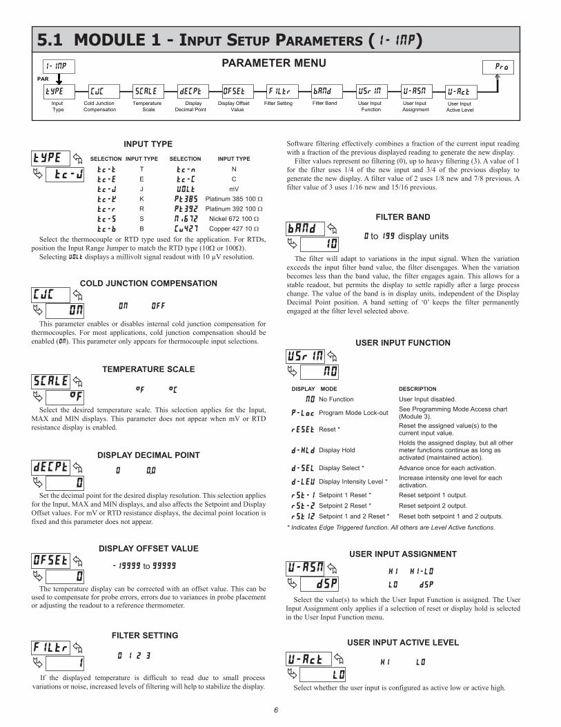
5.1 Module 1 - input setup paraMeters ()PARAMETER MENU
6
USER INPUT ACTIVE LEVEL
Select whether the user input is configured as active low or active high.
INPUT TYPE
DISPLAY DECIMAL POINT
Set the decimal point for the desired display resolution. This selection applies for the Input, MAX and MIN displays, and also affects the Setpoint and Display Offset values. For mV or RTD resistance displays, the decimal point location is fixed and this parameter does not appear.
FILTER SETTING
If the displayed temperature is difficult to read due to small process variations or noise, increased levels of filtering will help to stabilize the display.
FILTER BAND
The filter will adapt to variations in the input signal. When the variation exceeds the input filter band value, the filter disengages. When the variation becomes less than the band value, the filter engages again. This allows for a stable readout, but permits the display to settle rapidly after a large process change. The value of the band is in display units, independent of the Display Decimal Point position. A band setting of ‘0’ keeps the filter permanently engaged at the filter level selected above.
to display unitsSelect the thermocouple or RTD type used for the application. For RTDs, position the Input Range Jumper to match the RTD type (10Ω or 100Ω).
Selecting displays a millivolt signal readout with 10 µV resolution.
TEMPERATURE SCALE
Select the desired temperature scale. This selection applies for the Input, MAX and MIN displays. This parameter does not appear when mV or RTD resistance display is enabled.
DISPLAY OFFSET VALUE
The temperature display can be corrected with an offset value. This can be used to compensate for probe errors, errors due to variances in probe placement or adjusting the readout to a reference thermometer.
to
This parameter enables or disables internal cold junction compensation for thermocouples. For most applications, cold junction compensation should be enabled (). This parameter only appears for thermocouple input selections.
COLD JUNCTION COMPENSATION
USER INPUT FUNCTION
Select the value(s) to which the User Input Function is assigned. The User Input Assignment only applies if a selection of reset or display hold is selected in the User Input Function menu.
USER INPUT ASSIGNMENT
Software filtering effectively combines a fraction of the current input reading with a fraction of the previous displayed reading to generate the new display.
Filter values represent no filtering (0), up to heavy filtering (3). A value of 1 for the filter uses 1/4 of the new input and 3/4 of the previous display to generate the new display. A filter value of 2 uses 1/8 new and 7/8 previous. A filter value of 3 uses 1/16 new and 15/16 previous.
MODE
Reset *
Program Mode Lock-out
No FunctionDESCRIPTIONDISPLAY
Display Select * Advance once for each activation.
Setpoint 1 and 2 Reset *Setpoint 2 Reset *Setpoint 1 Reset *
Reset both setpoint 1 and 2 outputs.Reset setpoint 2 output.Reset setpoint 1 output.
Display Intensity Level * Increase intensity one level for each activation.
Display HoldHolds the assigned display, but all other meter functions continue as long as activated (maintained action).
Reset the assigned value(s) to the current input value.
See Programming Mode Access chart (Module 3).
User Input disabled.
T
E
J
NC
KmV
Platinum 385 100 Ω
SELECTION INPUT TYPE INPUT TYPESELECTION
BSR
Copper 427 10 ΩNickel 672 100 Ω
Platinum 392 100 Ω
* Indicates Edge Triggered function. All others are Level Active functions.

7
5.2 Module 2 - secondary Function paraMeters ()
PAR
Max Capture Delay Time
Max Display Enable
Min Display Enable
Access Code For Service Operations
Min Capture Delay TIme
Factory Service
Operations
2-SEC
HI-En HI-t LO-En LO-t FCS CodE
ProPARAMETER MENU
MIN DISPLAY ENABLE
MIN CAPTURE DELAY TIME
When the Input Display is below the present MIN value for the entered delay time, the meter will capture that display value as the new MIN reading. A delay time helps to avoid false captures of sudden short spikes.
to sec.
Enables the Minimum Display Capture capability.
MAX CAPTURE DELAY TIME
When the Input Display is above the present MAX value for the entered delay time, the meter will capture that display value as the new MAX reading. A delay time helps to avoid false captures of sudden short spikes.
to sec.
MAX DISPLAY ENABLE
Enables the Maximum Display Capture capability.
Entering Code 66 will overwrite all user settings with the factory settings. The meter will display and then return to . Press the PAR button to exit the module
Select to perform any of the Factory Service Operations shown below.
FACTORY SERVICE OPERATIONS
RESTORE FACTORY DEFAULT SETTINGS
Entering Code 50 will display the version (x.x) of the meter. The display then returns to . Press the PAR button to exit the module.
VIEW MODEL AND VERSION DISPLAY
Entering Code 85 toggles the selected RTD input display mode between a temperature or resistance readout. The resistance readout is useful for diagnostic purposes before and after calibration, or to display the measured resistance of a connected RTD probe.
For RTD type (Input Range Jumper in 10Ω position), resistance is displayed in ohms resolution. For all other RTD types (100Ω position), resistance is displayed in ohms resolution.
Upon entering Code 85, the meter displays either or to indicate temperature or resistance readout selected. The display then returns to . Press the PAR button to exit the module.
TOGGLE RTD INPUT DISPLAY MODE
The PAXLT uses stored calibration values to provide accurate temperature measurements. Over time, the electrical characteristics of the components inside the meter could slowly change, with the result being that the stored calibration values may no longer accurately define
the input circuit. For most applications, recalibration every 1 to 2 years should be sufficient.
Calibration for thermocouple inputs involves a voltage calibration and a cold junction calibration. It is recommended that both calibrations be performed. The voltage calibration must precede cold junction calibration.
Calibration of the meter should only be performed by persons experienced in calibrating electronic equipment. Allow a minimum 30 minute warm up before performing any calibration procedures. The following procedures should be performed at an ambient temperature of 15 to 35°C (59 to 95°F).
CAUTION: The accuracy of the calibration equipment will directly affect the accuracy of the meter.
10 OHM RTD Range Calibration1. Set the Input Range Jumper to 10 ohm position.2. With the display at , press the PAR key. Unit displays .3. Press SEL to select 10 ohm range. Display reads .4. Press PAR. Display reads .5. Apply a direct short to terminals RTD (4), TC (6) and COMM (7) using a
three wire link. Press PAR. Display reads for about 10 seconds.6. When the display reads , apply a precision resistance of 15 ohms (with
an accuracy of 0.01% or better) to terminals RTD, TC and COMM using a three wire link. Press PAR. Display reads for about 10 seconds.
7. When display reads , press PAR twice to exit calibration and return to the normal display mode.
100 OHM RTD Range Calibration1. Set the Input Range Jumper to 100 ohm position.2. With the display at , press the PAR key. Unit displays .3. Press SEL twice to select 100 ohm range. Display reads .4. Press PAR. Display reads .5. Apply a direct short to terminals RTD (4), TC (6) and COMM (7) using a
three wire link. Press PAR. Display reads for about 10 seconds.6. When the display reads , apply a precision resistance of 300 ohms (with
an accuracy of 0.01% or better) to terminals RTD, TC and COMM using a three wire link. Press PAR. Display reads for about 10 seconds.
7. When display reads , press PAR twice to exit calibration and return to the normal display mode.
CALIBRATION
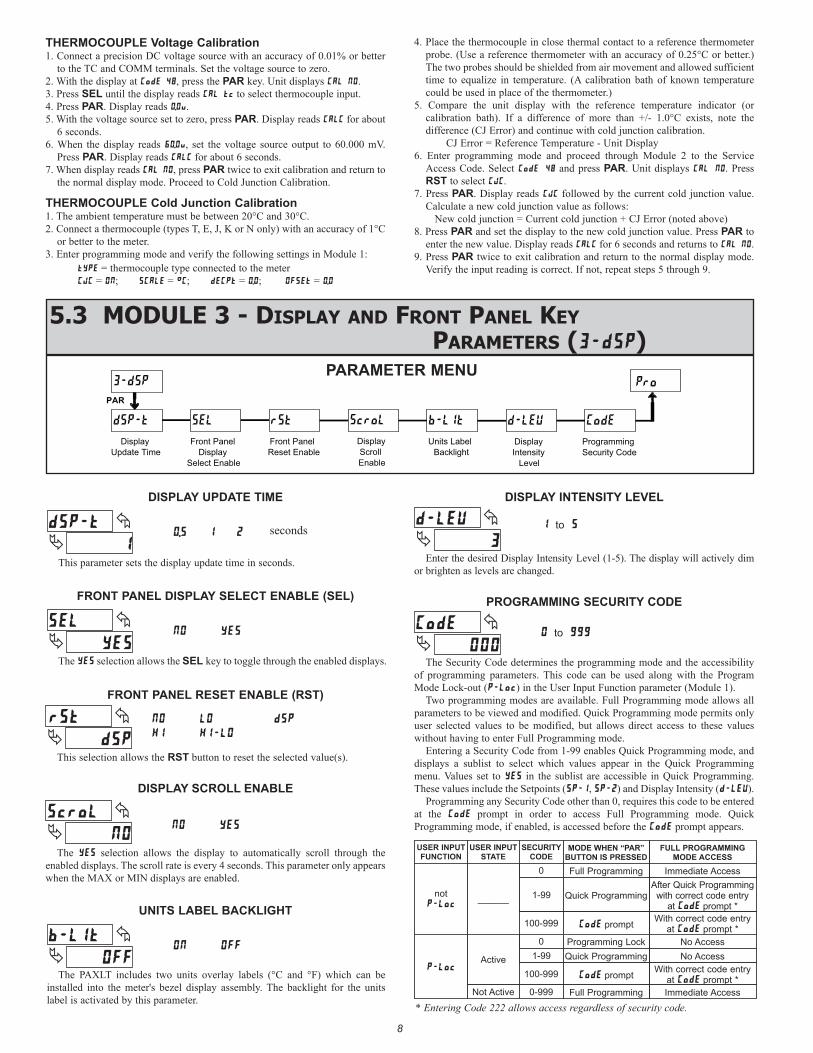
This parameter sets the display update time in seconds.
DISPLAY UPDATE TIME
5.3 Module 3 - display and Front panel Key paraMeters ()
PAR
Pro
Front Panel Display
Select Enable
Display Update Time
Front Panel Reset Enable
Programming Security Code
3-dSP
dSP-t SEL rSt CodE
Display Intensity
Level
d-LEVScroL
Display Scroll Enable
b-LIt
Units Label Backlight
PARAMETER MENU
This selection allows the RST button to reset the selected value(s).
FRONT PANEL RESET ENABLE (RST)
The selection allows the display to automatically scroll through the enabled displays. The scroll rate is every 4 seconds. This parameter only appears when the MAX or MIN displays are enabled.
DISPLAY SCROLL ENABLE
Enter the desired Display Intensity Level (1-5). The display will actively dim or brighten as levels are changed.
DISPLAY INTENSITY LEVEL
The Security Code determines the programming mode and the accessibility of programming parameters. This code can be used along with the Program Mode Lock-out () in the User Input Function parameter (Module 1).
Two programming modes are available. Full Programming mode allows all parameters to be viewed and modified. Quick Programming mode permits only user selected values to be modified, but allows direct access to these values without having to enter Full Programming mode.
Entering a Security Code from 1-99 enables Quick Programming mode, and displays a sublist to select which values appear in the Quick Programming menu. Values set to in the sublist are accessible in Quick Programming. These values include the Setpoints (, ) and Display Intensity ().
Programming any Security Code other than 0, requires this code to be entered at the prompt in order to access Full Programming mode. Quick Programming mode, if enabled, is accessed before the prompt appears.
PROGRAMMING SECURITY CODE
to
to
USER INPUT FUNCTION
USER INPUT STATE
SECURITY CODE
MODE WHEN “PAR” BUTTON IS PRESSED
FULL PROGRAMMING MODE ACCESS
0 Full Programming Immediate Access
not
______ 1-99 Quick ProgrammingAfter Quick Programming
with correct code entry at prompt *
100-999 prompt With correct code entry at prompt *
0 Programming Lock No Access
Active 1-99 Quick Programming No Access
100-999 prompt With correct code entry at prompt *
Not Active 0-999 Full Programming Immediate Access
* Entering Code 222 allows access regardless of security code.
8
THERMOCOUPLE Voltage Calibration1. Connect a precision DC voltage source with an accuracy of 0.01% or better
to the TC and COMM terminals. Set the voltage source to zero.2. With the display at , press the PAR key. Unit displays .3. Press SEL until the display reads to select thermocouple input.4. Press PAR. Display reads .5. With the voltage source set to zero, press PAR. Display reads for about
6 seconds.6. When the display reads , set the voltage source output to 60.000 mV.
Press PAR. Display reads for about 6 seconds.7. When display reads , press PAR twice to exit calibration and return to
the normal display mode. Proceed to Cold Junction Calibration.
THERMOCOUPLE Cold Junction Calibration1. The ambient temperature must be between 20°C and 30°C.2. Connect a thermocouple (types T, E, J, K or N only) with an accuracy of 1°C
or better to the meter.3. Enter programming mode and verify the following settings in Module 1:
= thermocouple type connected to the meter = ; = ; = ; =
4. Place the thermocouple in close thermal contact to a reference thermometer probe. (Use a reference thermometer with an accuracy of 0.25°C or better.) The two probes should be shielded from air movement and allowed sufficient time to equalize in temperature. (A calibration bath of known temperature could be used in place of the thermometer.)
5. Compare the unit display with the reference temperature indicator (or calibration bath). If a difference of more than +/- 1.0°C exists, note the difference (CJ Error) and continue with cold junction calibration. CJ Error = Reference Temperature - Unit Display
6. Enter programming mode and proceed through Module 2 to the Service Access Code. Select and press PAR. Unit displays . Press RST to select .
7. Press PAR. Display reads followed by the current cold junction value. Calculate a new cold junction value as follows:
New cold junction = Current cold junction + CJ Error (noted above)8. Press PAR and set the display to the new cold junction value. Press PAR to
enter the new value. Display reads for 6 seconds and returns to .9. Press PAR twice to exit calibration and return to the normal display mode.
Verify the input reading is correct. If not, repeat steps 5 through 9.
The selection allows the SEL key to toggle through the enabled displays.
FRONT PANEL DISPLAY SELECT ENABLE (SEL)
The PAXLT includes two units overlay labels (°C and °F) which can be installed into the meter's bezel display assembly. The backlight for the units label is activated by this parameter.
UNITS LABEL BACKLIGHT
seconds

9
5.4 Module 4 - setpoint output paraMeters ()
PAR
Setpoint Action
Setpoint Select
Setpoint Value
Output Reset Action
Hysteresis Value
Off Time Delay
On Time Delay
Output Reset With Display
Reset
SPSEL
4-SPt
Act-n SPt-n HYS-n tON-n tOF-n
rSt-n rEn-n
Pro
Standby Operation
Stb-n
Enb-n
Setpoint Enable
Probe Burn-out
Action
brn-n
PARAMETER MENU
Select the Setpoint Output to be programmed, starting with Setpoint 1. The “” in the following parameters reflects the chosen Setpoint number. After the selected setpoint is completely programmed, the display returns to . Repeat steps for Setpoint 2 if both Setpoints are being used. Select to exit the Setpoint programming module.
SETPOINT SELECT
Select to enable Setpoint and access the setup parameters. If is selected, the unit returns to and Setpoint is disabled.
SETPOINT ENABLE
Enter the action for the selected setpoint (output). See Setpoint Output Figures for a visual detail of each action.
SETPOINT ACTION
High Acting, with balanced hysteresisLow Acting, with balanced hysteresisHigh Acting, with unbalanced hysteresisLow Acting, with unbalanced hysteresis
=
=
=
=
OUTPUTSTATE
OFF ON
Hys
SP + ½Hys
SP
SP - ½Hys
OFF
TRIGGER POINTS
High Acting (Balanced Hys) =
OUTPUTSTATE
OFF ON
Hys
SP + ½Hys
SP
SP - ½Hys
OFF
TRIGGER POINTS
Low Acting (Balanced Hys) =
OUTPUTSTATE
OFF ON
Hys
SP + Hys
SP
OFF
TRIGGER POINTS
Low Acting (Unbalanced Hys) =
OUTPUTSTATE
OFF ON
Hys
SP
SP - Hys
OFF
TRIGGER POINTS
High Acting (Unbalanced Hys) =
SETPOINT VALUE
Enter the desired setpoint value. The decimal point position for the setpoint and hysteresis values follow the selection set in Module 1.
to
HYSTERESIS VALUE
to
Enter desired hysteresis value. See Setpoint Output Figures for visual explanation of how setpoint output actions (balanced and unbalanced) are affected by the hysteresis. When the setpoint is a control output, usually balanced hysteresis is used. For alarm applications, usually unbalanced hysteresis is used. For unbalanced hysteresis modes, the hysteresis functions on the low side for high acting setpoints and functions on the high side for low acting setpoints.Note: Hysteresis eliminates output chatter at the switch point, while time delay
can be used to prevent false triggering during process transient events.
OFF TIME DELAY
to Sec
Enter the time value in seconds that the output is delayed from turning off after the trigger point is reached. A value of 0.0 allows the meter to update the output status per the response time listed in the Specifications.
ON TIME DELAY
Enter the time value in seconds that the output is delayed from turning on after the trigger point is reached. A value of 0.0 allows the meter to update the output status per the response time listed in the Specifications.
to Sec
Enter the reset action of the output. See figure for details.
= Automatic action; This action allows the output to automatically reset off at the trigger points per the Setpoint Action shown in Setpoint Output Figures. The “on” output may be manually reset (off) immediately by the front panel RST button or user input.The output remains off until the trigger point is crossed again.
OUTPUT RESET ACTION
10
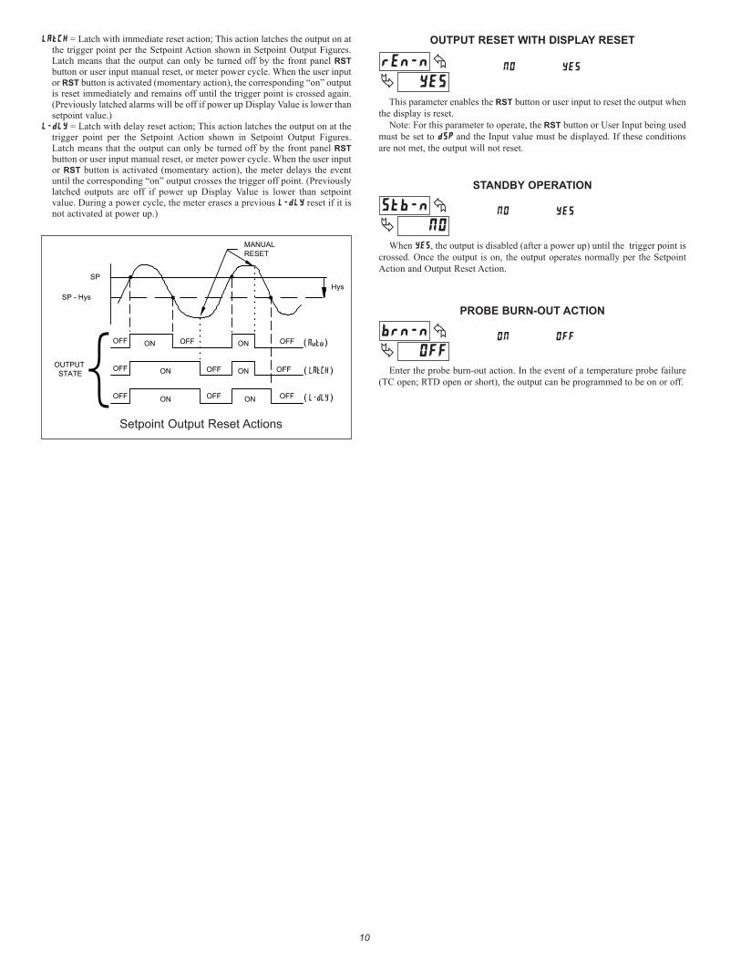
This parameter enables the RST button or user input to reset the output when the display is reset.
Note: For this parameter to operate, the RST button or User Input being used must be set to and the Input value must be displayed. If these conditions are not met, the output will not reset.
OUTPUT RESET WITH DISPLAY RESET
When , the output is disabled (after a power up) until the trigger point is crossed. Once the output is on, the output operates normally per the Setpoint Action and Output Reset Action.
STANDBY OPERATION
Enter the probe burn-out action. In the event of a temperature probe failure (TC open; RTD open or short), the output can be programmed to be on or off.
PROBE BURN-OUT ACTION
= Latch with immediate reset action; This action latches the output on at the trigger point per the Setpoint Action shown in Setpoint Output Figures. Latch means that the output can only be turned off by the front panel RST button or user input manual reset, or meter power cycle. When the user input or RST button is activated (momentary action), the corresponding “on” output is reset immediately and remains off until the trigger point is crossed again. (Previously latched alarms will be off if power up Display Value is lower than setpoint value.)
= Latch with delay reset action; This action latches the output on at the trigger point per the Setpoint Action shown in Setpoint Output Figures. Latch means that the output can only be turned off by the front panel RST button or user input manual reset, or meter power cycle. When the user input or RST button is activated (momentary action), the meter delays the event until the corresponding “on” output crosses the trigger off point. (Previously latched outputs are off if power up Display Value is lower than setpoint value. During a power cycle, the meter erases a previous reset if it is not activated at power up.)
OUTPUTSTATE
OFF ON
HysSP
AutoOFF ON OFF
OFF ON OFF ON OFF
OFF ON OFF ON OFF
MANUALRESET
LAtCH
L-dLY
SP - Hys
( )
( )
( )
Setpoint Output Reset Actions

11
Set
poin
t A
ctio
nS
etpo
int
Sel
ect
Set
poin
t V
alue
Out
put R
eset
A
ctio
nH
yste
resi
s V
alue
Off
Tim
e D
elay
On
Tim
e D
elay
Out
put R
eset
W
ith D
ispl
ay
Res
et
SPSEL
4-SPt
Act-n
SPt-n
HYS-n
tON-n
tOF-n
rSt-n
rEn-n
Sta
ndby
O
pera
tion
Stb-n
Fron
t Pan
el
Res
et E
nabl
eFr
ont P
anel
D
ispl
ay
Sel
ect E
nabl
e
Dis
play
U
pdat
e Ti
me
dSP-t
SEL
rSt
3-dSP
Dis
play
In
tens
ity
Leve
l
d-LEV
Pro
gram
min
g S
ecur
ity C
ode
CodE
Dis
play
Offs
et
Val
ueIn
put
Type
tYPE
Col
d Ju
nctio
n C
ompe
nsat
ion
CJC
1-INP
Dis
play
D
ecim
al P
oint
dECPt
OFSEt
USrIN
Use
r Inp
ut
Func
tion
Filte
r Ban
d
bANd
U-ASN
Use
r Inp
ut
Ass
ignm
ent
LO-En
Min
Dis
play
E
nabl
eM
ax C
aptu
re
Del
ay T
ime
Max
Dis
play
E
nabl
e
HI-En
HI-t
2-SEC
Min
Cap
ture
D
elay
TIm
e
LO-t
Fact
ory
Ser
vice
O
pera
tions
FCS
Acc
ess
Cod
e Fo
r Ser
vice
O
pera
tions
CodE
PAR
SEL
NO
Pro
Exi
t P
rogr
amm
ing
End
PAR
SEL
SEL
SEL
SEL
PAR
PAR
PAR
SCALE
Tem
pera
ture
S
cale
FILtr
Filte
r Set
ting
ScroL
Dis
play
S
crol
l E
nabl
e
Enb-n
Set
poin
t E
nabl
e
Use
r Inp
ut
Act
ive
Leve
l
U-Act
Uni
tsLa
bel
Bac
klig
ht
b-LIt
brn-n
Pro
be
Bur
n-ou
t A
ctio
n
paXlt prograMMing QuicK overvieW
Pre
ss P
AR
key
to e
nter
P
rogr
amm
ing
Mod
e.
LIMITED WARRANTYThe Company warrants the products it manufactures against defects in materials and workmanship for a period limited to two years from the date of shipment, provided the products have been stored, handled, installed, and used under proper conditions. The Company’s liability under this limited warranty shall extend only to the repair or replacement of a defective product, at The Company’s option. The Company disclaims all liability for any affirmation, promise or representation with respect to the products.The customer agrees to hold Red Lion Controls harmless from, defend, and indemnify RLC against damages, claims, and expenses arising out of subsequent sales of RLC products or products containing components manufactured by RLC and based upon personal injuries, deaths, property damage, lost profits, and other matters which Buyer, its employees, or sub-contractors are or may be to any extent liable, including without limitation penalties imposed by the Consumer Product Safety Act (P.L. 92-573) and liability imposed upon any person pursuant to the Magnuson-Moss Warranty Act (P.L. 93-637), as now in effect or as amended hereafter.No warranties expressed or implied are created with respect to The Company’s products except those expressly contained herein. The Customer acknowledges the disclaimers and limitations contained herein and relies on no other warranties or affirmations.
Red Lion ControlsHeadquarters20 Willow Springs CircleYork PA 17406Tel +1 (717) 767-6511Fax +1 (717) 764-0839
Red Lion ControlsChina
Unit 302, XinAn PlazaBuilding 13, No.99 Tianzhou Road
ShangHai, P.R. China 200223Tel +86 21 6113 3688Fax +86 21 6113 3683
Red Lion ControlsEurope
Softwareweg 9NL - 3821 BN AmersfoortTel +31 (0) 334 723 225Fax +31 (0) 334 893 793
Red Lion ControlsIndia
201-B, 2nd Floor, Park CentraOpp 32 Mile Stone, Sector-30
Gurgaon-122002 Haryana, IndiaTel +91 984 487 0503