for - nasa · summary of results ..... organization of this report ... arp subnetting
TRANSCRIPT

NASA-CR-l?1334
Final Reportfor the
SBIR 87-1 (Phase II) Program
High Speed Packet Switching
/
?.49
Prepared in Response toContract No. NAS 5-30629
for
National Aeronautics and Space Administration
Goddard Space Flight CenterGreenbelt Road
Greenbelt, Maryland 20771
October 1991
(NASA-CR-191334) HIGH
SWITCHING Final Report
43 p
SPEED PACKET
(Proteon)
N94-13177
Unclas
G3/62 0186517
Prepared by
Proteon, Inc.
Two Technology DriveWestborough, MA 01581
Tel. No.: (508) 898-2800 Fax No.: (508) 366-8901
https://ntrs.nasa.gov/search.jsp?R=19940008704 2018-06-14T13:26:31+00:00Z

Final Report - High Speed Packet SwitchingNASA Contract No. NAS 5-30629
1. Introduction
1.1. Background
1.2. Objectives
1.3.
1.4.
TABLE OF CONTENTS
Summary of Results ............................................................................................................................
Organization of this Report ...............................................................................................................
2. Processor Selection .................................................................................................................................
2.1. Methodology .........................................................................................................................................
2.2. Choosing the Processor .......................................................................................................................
3. SNIPE/RIG Implementation ..................................................................................................................
3.1. Selection of Hardware .........................................................................................................................
3.1.1. Central Processor Card - IV9001 from Ironics ............................................................................
3.1.2. Ethernet Interface - SBE VLAN-E ................................................................................................
3.1.3. Serial Interface - SBE VCOM-4 .....................................................................................................
3.1.4. 802.5 Token Ring - Proteon VME 802.5 .......................................................................................
3.1.5. Configuration SRAM - Motorola 512K SRAM ............................................................................
3.1.6. VME Enclosure - MUPAC custom ................................................................................................
3.1.7. Final configuration ............................................................................................................................
3.2. Central Processor Code ......................................................................................................................
3.2.1.
3.2.2.
3.3.
New Code ...........................................................................................................................................
Code Porting ......................................................................................................................................
Firmware ..............................................................................................................................................
1
1
1
1
1
3
3
3
5
5
5
5
6
6
6
6
6
7
7
7
7
proteon - i- October 1991
FinalReport- HighSpeedPacketSwitchingNASAContractNo.NAS5-30629
3.3.1.InterfaceFirmware ...........................................................................................................................
3.3.2. Bootstrap Firmware .........................................................................................................................
3.4. SNIPE/RIG Functional Specification ................................................................................................
3.4.1. IP Forwarding Algorithm ................................................................................................................
3.4.2. Subnetting ..........................................................................................................................................
3.4.3. ICMP Implementation .....................................................................................................................
3.4.4. No network numbers on serial lines ..............................................................................................
3.4.5. Access control ....................................................................................................................................
3.4.6. EGP Implementation ........................................................................................................................
3.4.7. OSPF Implementation ......................................................................................................................
3.4.8. RIP Implementation .........................................................................................................................
3.4.9. ARP Subnetting .................................................................................................................................
3.4.10. SNMP Implementation ...................................................................................................................
3.4.11. Reliability .........................................................................................................................................
3.4.12. Standards .........................................................................................................................................
3.4.13. Interfaces ..........................................................................................................................................
3.4.14. Chassis ..............................................................................................................................................
3.4.15. Console Access ................................................................................................................................
3.4.16. Performance ....................................................................................................................................
3.5. The SNIPE/RIG Final Acceptance Test ...........................................................................................
4. SNIPE/RIG System Speed-Up ...............................................................................................................
4.1. The Path to 20,000 Packet Per Second and 20 Mbps .....................................................................
8
8
8
9
I0
10
11
11
11
12
12
13
13
14
14
15
15
15
15
15
17
17
proteon - ii - October 1991

FinalReport- HighSpeedPacketSwitchingNASAContractNo.NAS5-30629
4.1.1.HardwareModificationstotheSNIPE/RIGSystem ....................................................................
4.1.2. Software Changes made to the SNIPE/RIG System ....................................................................
4.1.2.1. The Fastpath IP Forwarder Code ...............................................................................................
4.1.2.2. The IP Cache ..................................................................................................................................
4.1.2.3. Improved Interface Board I/O Models .......................................................................................
4.1.2.4. Hardware is the Ultimate Bottleneck ..........................................................................................
4.2. Original 29000-based Router Pert_rmance Estimates Revisited ...................................................
5. Multiprocessor Routing ..........................................................................................................................
5.1. Interprocessor Communication ..........................................................................................................
5.2. Results ...................................................................................................................................................
6. Selection of High-Speed Interprocessor Communication Method ...................................................
6.1. Functional Options ..............................................................................................................................
6.1.1. Speed in Bits Per Second .................................................................................................................
6.1.2. Speed in Packets Per Second ..........................................................................................................
6.1.3. Number of Ibus Nodes .....................................................................................................................
6.1.4. Cross-system Control Information .................................................................................................
6.1.5. Physical package ...............................................................................................................................
6.1.6. Maintenance ......................................................................................................................................
6.2. Design Options .....................................................................................................................................
6.2.1. Packet-level Space Division Ibus ....................................................................................................
6.2.2. Packet-level Time Division Ibus .....................................................................................................
6.2.3. Word-level Time Division Ibus .......................................................................................................
17
18
18
19
19
21
22
24
24
25
26
26
26
26
26
26
27
27
27
27
27
28
proteon - iii- October 1991

FinalReport- HighSpeedPacketSwitchingNASAContractNo.NAS5-30629
6.2.4.
6.3.Contention- HowFastwill it go
6.4.ImprovingSwitchThroughput
6.4.1.ReorderingtheInputQueue
Comparison........................................................................................................................................
6.4.2. Space Division and Time Division ..................................................................................................
6.4.3. Summary - Queueing and Loading on the Switch .......................................................................
6.4.4. Limits to the Analysis ......................................................................................................................
6.5. Building a Switch .................................................................................................................................
6.5.1. Space Division: Dealing with Port Contention ............................................................................
6.5.2. Time Division: Comparing Clock Speeds ....................................................................................
6.5.3. Time-division: Dealing with Memory Bandwidth .......................................................................
6.6. Preliminary Selection of Design Approach ......................................................................................
7. Proteon CNX-500 Architecture .............................................................................................................
7.1. CNX-500 Motherboard .......................................................................................................................
7.2. CNX-500 Interface Modules ...............................................................................................................
7.3. CNX-500 Block Diagram ....................................................................................................................
8. Summary and Conclusions ....................................................................................................................
28
28
29
30
30
31
32
32
32
33
33
33
35
35
35
37
38
proteon - iv - October 1991

FinalReport- High Speed Packet SwitchingNASA Contract No. NAS 5-30629
1. Introduction
This document constitutes the final report prepared by Proteon, Inc. of Westborough, Massachusetts under con-
tract NAS 5-30629 entitled High-Speed Packct Switching (SBIR 87-1, Phase II) prepared for NASA-Greenbelt,
Maryland.
1.1. Background
Over the next several years, NASA is anticipating a greatly increased level of traffic over their Earth Observa-
tion System (EOS). In order to efficiently distribute this EOS information, NASA requires a very high perfor-mance backbone network.
1.2. Objectives
The primary goal of this research project is to use the results of the SBIR Phase I effort to develop a sound,expandable hardware and software router architecture capable of forwarding 25,000 packets per second through
the router and passing 300 megabits per second on the router's internal busses.
1.3. Summary of Results
The work being delivered under this contract received its funding from three different sources: The SNIPE/RIG
contract (Contract Number F30602-89-C-0014, CDRL Sequence Number A002), the SBIR contract, and Proteon.The SNIPE/RIG and SBIR contracts had many overlapping requirements, which allowed the research done under
SNIPE/RIG to be applied to SBIR. Proteon funded all of the work to develop new router interfaces other than
FDDI, in addition to funding the productization of the router itself. The router being delivered under SBIR will
be a fully product-quality machine.
The work done during this contract produced many significant iindings and results, summarized here and
explained in detail in later sections of this report.
The SNIPE/RIG contract was completed. That contract had many overlapping requirements with the SBIR con-tract, and resulted in the successful demonstration and delivery of a high speed router. The development that
took place during the SNIPE/RIG contract produced findings that included the choice of processor and an under-
standing of the issues surrounding interprocessor communications in a multiprocessor environment. Many
significant speed enhancements to the router software were made during that time.
Under the SBIR contract (and with help from Proteon-funded work), it was found that a single processor router
achieved a throughput significantly higher than originally anticipated. For this reason, a single processor routerwas developed and the final delivery under this contract will include a single processor CNX-500 router. Therouter and its interface boards (2 FDDIs and 2 dual-ethernets) are all product-quality components.
1.4. Organization of this Report
Section 2 below discusses the methodology that was used to choose the processor and compiler for this contrac-tual effort from the available candidates.
Section 3 is a summary of the implementation effort for the SNIPE/RIG contract, which provided invaluableinformation and experience for this study. The hardware selection and code port to the hardware for that con-tract is discussed, and a SNIPE/RIG functional specification and summary of the Final Acceptance Test is also
provided.
proteon - 1- October 1991

Final Report - High Speed Packet SwitchingNASA Contract No. NAS 5-30629
Section 4 discusses the effort that brought the throughput of the SNIPE/RIG router up to 20,000 packets per
second and 20 megabits per second. Section 5 presents the findings of the work to convert the SNIPE/RIGrouter to a multiprocessor environment. The experience gained from these efforts was used extensively in decid-
ing on the final architecture used in this study.
Section 6 describes a scalable architecture that could be used to turn the router delivered under this contract into
a multiple router architecture.
Section 7 discusses the final, chosen architecture of the router that is being delivered as partial fulfillment of thiscontract.
Section 8 presents a summary and the conclusions of this report.
proteon - 2- October 1991

FinalReport- HighSpeedPacketSwitchingNASAContractNo.NAS5-30629
2. ProcessorSelection
This section presents a technical analysis that was perforrned for the purpose of selecting the processor most
appropriate for use in a high-speed router application.
An examination of CISC instructions necessary to forward a packet has shown that very few different instruction
types are needed and that these instruction t}qges are RISC class instructions. Complex instructions (e.g. those
that perform floating point arithmetic) are generally not used in router applications, and thus are not considered
beneficial when evaluating a particular processor.
2.1. Methodology
An examination of various RISC processors was carried out by Dr. David Clark by compiling a section of router
code and examining the instructions generated.
Inst Reads Writes
68020 98 29 4
SPARC 146 29 688000 121 21 3
29000 154 23 3
Although the count of instructions increases, the one cycle execution speed of any RISC processor would for-
ward a packet faster than the 68020 CISC. Based on just instruction execution, the 88000 is shown as the supe-
rior processor.
The reads and writes to data memory count even more than the instruction accesses. The RISC processors all
have ways of keeping the one cycle instruction execution going by either bursting in instructions or executingfrom cache. Random accesses to data take several cycles and thus the read and write instructions represent
several instruction accesses, usually about 4 or 5 each.
Several other features of the RISC architectures were also examined with two being considered as critical for
router performance. The separation of instruction and data paths via a "harvard" architecture will allow the pro-cessor to continue fetching instructions while data is being accessed. An architecture that provides register win-
dowing, a large number of registers that can be segmented as storage for each routine, would also cut down onthe cost of subroutines.
2.2. Choosing the Processor
The 29000 has a modified harvard architecture with separate instruction and data buses but a common address
bus. It also has a modified register window by providing 128 registers for process stack along with 64 global
registers.
The 88000 has only 32 general purpose registers with no register windowing and has a full harvard architecture.The 88000 is actually a three chip solution with the 88100 CPU and two 88200 bus units, one for data and onefor instructions.
The SPARC has a single bus and thus data and instruction accesses collide.
Several other features of the 29000 further indicated its suitability as a router engine. The 29000 supports a burst
proteon - 3 - October 1991

FinalReport- HighSpeedPacketSwitchingNASA Contract No. NAS 5-30629
load of data and thus the entire packet header could be read into registers with only a single cycle delay foreach read after the first access. The large number of registers would make this practical. The 'C' compiler does
not support this feature well and thus some hand assembly might be required.
Finally, cost and direction of the candidate processors has to be evaluated. As mentioned before, the 88000 is a
three chip set and the cost will probably remain high. The 29000 and the SPARC are single chips and shouldmaintain a good cost margin against the 88000. As for future direction, both the 88000 and the SPARC are tar-
getted for work station and file server applications. The 29000 seems to have conceded this market and is target-ted to controller applications. Thus we feel that the 88000 and SPARC will evolve features that will be
superfluous while the 29000 will evolve as a limited operational engine which is closer to what a router is.
proteon .4 - October 1991

FinalReport- HighSpeedPacketSwitchingNASAContractNo.NAS5-30629
3. SNIPE/RIGImplementation
The research carried out during the SNIPE/RIG contract was an integral part of the development that led to thefinal delivery under the SBIR contract. Extensive experience was gained in the operation of and the best way to
program the 29000, and the advantages and disadvantages of running the router code in a multiprocessorenvironment were explored and evaluated.
Any implementation of an internetworking router should demonstrate multi-LAN/WAN connectivity. The
SNIPE/RIG implementation demonstrated LAN connectivity to Ethernet and 802.5 Token Ring and WAN con-nectivity via Synchronous Serial Line and X.25.
This section first describes the reasoning behind the choices of each of the hardware components of theSNIPE/RIG router. Then the development process for the new code to run on that hardware is disussed.
Finally, a functional specification of the SNIPE/RIG router is given and the results of the SNIPE/RIG Final
Acceptance Test are presented.
3.1. Selection of Hardware
Time and practical considerations mandated the selection of industry standard hardware with a reasonable inter-
connection speed. A VME standard backplane promised the speed, availability and standardization needed.
The VME backplane can support high speed transfer via "burst mode" accesses to give a transfer rate in excessof 100 Mbytes/sec. None of the cards selected for the SNIPE/RIG supported burst mode but even the singletransfer rate of 40 Mbytes/sec is considerably faster than the multibus backplane of the Proteon p4200 product.
The selection of the VME would allow the future upgrade to burst mode peripherals when they are available.
Additional consideration had to be given to the components of the SNIPE/RIG implementation with respect to
dependability (it had to exist - and work!), and flexibility.
3.1.1. Central Processor Card - IV9001 t¥om Ironies
The central processor board for the router had to support a console, have a large memory available to interface
boards, and support the AMD29000 harvard architecture. The Ironics IV9001 was the only card at this time thathad a reasonable track record (in order to qualify as dependable) and sufficient capabilities to support a router.
The multifunction 68692 peripheral chip on the IV9001 supports two consoles and provides a system clock
interrupt. The 29000 chip provides an internal clock but it is difficult to mask because it traps instead of inter-
rupts. This makes the internal clock not as useful as it could be.
The entire 2 Megabytes of memory is visible to the VME bus. The memory is accelerated by a data cache thatis between the memory and all its clients. This is important because a typical cache system would have the
cache just between the main memory and the processor with complex "snooping" required to keep track of anyupdates to main memory from the VME bus. With the cache between the memory and all clients, the cache is
always in synch with main memory.
The IV9001 supports VME interrupts from the interface cards and the ability to lock the VME bus. The latter
feature is useful for any multiprocessor designs.
Other CPU cards based on the 29000 were still in preliminary design and debug and we did not feel that they
would be dependable.
proteon - 5 - October 1991

Final Report - High Speed Packet SwitchingNASA Contract No. NAS 5-30629
3.1.2. Ethernet Interface - SBE VLAN-E
The VLAN-E ethemet card is a "smart" peripheral card with an onboard 68020 processor to support the Ethernet
LANCE chip along with memory for both 68020 program space and packet buffers. SBE has a record as a reli-
able supplier of dependable hardware.
The "smart" card was preferred to a "dumb" card with just an ethernet chip set due to interface flexibility. Withthe onboard 68020, the protocol between the central processor and the interface card could be defined to offload
the central processor. Alternatively, the 68020 could be programmed to model any "dumb" chipset interface.
The Motorola ethernet card had memory contention problems between the ethernet chip and the 68020. When
the ethemet chip was accessing memory, the 68020 would be locked out.
3.1.3. Serial Interface - SBE VCOM-4
The VCOM-4 is also a "smart" peripheral card with a 68020 processor. This card supports two 85c30 serial con-
troller chips. Each 85c30 can support a single T1 line.
For the WAN interface, the choice of a "smart" card was a necessity. The same WAN card has to support the
Proteon Serial Line protocol and the X.25 protocol. Intelligence is needed on the card to handle the low latency
requirements of serial line chips and the different protocol requirements.
Other VME serial cards were eliminated due to either fewer ports available or the inability to support T1 line
rates.
3.1.4. 802.5 Token Ring - Proteon VME 802.5
The Proteon 802.5 card was a "safe" choice based on the dependability of in house support and the familiarityof the code needed. There were no reliable "smart" cards available for this interface.
3.1.5. Configuration SRAM - Motorola 512K SRAM
This card also represented the "safe" choice. This is not a cutting edge product and dependability and reliabilitywere the main selection criteria.
The large memory capacity of the board (512K bytes) ",allowed for its use as packet buffer/global system memory
as well as router configuration storage.
3.1.6. VME Enclosure - MUPAC custom
A custom rack mount enclosure with a VME chassis and power supply was chosen with MUPAC as the sup-
plier. The different interfaces needed some customized connector mountings and the nearby location of MUPACwould allow interactive contact with the supplier if mechanical problems needed to be worked out.
3.1.7. Final configuration
The final configuration consisted of:
proteon - 6 - October 1991

FinalReport- HighSpeedPacketSwitchingNASAContractNo.NAS5-30629
A) MUPAC 20 VME slot chassis with power supply
B) An IRONICS IV9001 29000 based CPUC) 2 SBE VLAN-E ethemet interfaces
D) 2 SBE VCOM-4 serial interfacesE) 2 Proteon 802.5 4mbit Token Ring interfaces
F) A Motorola 512Kbyte SRAM card.
3.2. Central Processor Code
The Proteon router code consists of several protocol forwarders and interface handlers, a set of utilities to sup-
port them, the MOS operating system to supply services like memory and timer management and some general
library routines like printf0. There is also the DDT debugger for system development and trouble shooting.
All of this code resides on the CPU board and executes on a single processor. The router code communicates
with its interfaces with device specific drivers. These drivers must be modified or rewritten for each new deviceadded to a handler family. For example, the VLAN-E driver had to be written to pass Ethernet frames betweenthe VLAN-E board and the Ethernet handler which then passed packets up to the IP forwarder for processing.
3.2.1. New Code
Most new code for the SNIPE/RIG project consisted of rewriting the low level code that was already written in
the assembler of an existing processor (68020). This code fell into one of several categories.
Startup routines like RAM sizing.
Interrupt handlers for on board facilities like the timerand console driver.
Processor dependent routines like context switching with register
saving and first level interrupt handlers.
Small "accelerator" routines that could be in 'C' like the IP
checksum routine.
Comparatively large scale development was done in 'C' The two main tasks were the device drivers for eachtype of interface card and the DDT debugger routines to support breakpoints and code disassembly.
3.2.2. Code Porting
With the bulk of the router code written in 'C' and having had it ported to other processors in the past, most of
it compiled and executed without any problems. In fact, when the router first was integrated and running, someof the team had no idea of what it should do and had to call other team members to confirm that it was a work-
ing router.
Due to the strict alignment restrictions of the 29000 processor (all long words must fall on 4 byte boundaries)several unaligned access traps were uncovered over the course of integration testing. These misalignments were
acceptable on other processors but cause performance degradation due to the double fetch that most CISC pro-cessors will perform. Correcting them in the 'C' code helped improve the overall performance of the portablerouter code.
proteon - 7 - October 1991
FinalReport- HighSpeedPacketSwitchingNASAContractNo.NAS5-30629
3.3. Firmware
The term "firmware" describes all code that resides in PROMs throughout the router. This consisted of firmware
code for the "smart" interface boards and also the bootstrap loader PROMS on the CPU.
3.3.1. Interface Firmware
The two "smart" interface cards, the VLAN-E and the VCOM-4 also had to be programmed. These cards had
the possibility of a flexible interface that could be programmed into the onboard ROMs which would start upwhen the VME reset was complete. A general purpose "smart card" interface was used where the interface card
would look for two message queues that were set up by the CPU. One queue was for commands from the CPUto the interface and the other was for interface replies or requests to the CPU.
Both cards were programmed to run a simple looping routine that would process the command queue and putresponses on the reply queue while servicing the interface device. The most common commands would be
descriptors for full transmit buffers or empty receive buffers. Other commands would be board reset or requestsfor statistics. All commands had some acknowledgment in the reply queue except for interface reset.
3.3.2. Bootstrap Firmware
The IV9001 processor has 256 Kbytes of PROM which contain a program, the bootstrap loader. This loaderworks with the interface card firmware to load the main router code from a file server over the internet.
The bootstrap loader has on its lowest level a combination device driver/handler that separates the IP packets
from the interface frames and passes them to a TF/'P handler. The file being transferred by TFTP is an absoluteloader (.ldb) file that is passed to higher routines which load the image data from the file into memory. The .ldbformat also includes a start address which is jumped to at the conclusion of a successful load.
If the router should reset due to some software problem or hardware fault, the same bootstrap loader can also
dump the memory image of the router along with current register values to a file server before reloading a freshimage of the software. This image can then be analyzed to determine the fault.
3.4. SNIPE/RIG Functional Specification
3.4.1. System Overview
The SNIPE/RIG IP (Intemet Protocol) packet forwarder provides packet forwarding in accordance with the for-
warding rules of the TCP/IP family of network protocols. This allows the router to support communication
between systems using the TCP/IP network protocols on different physical networks. The physical networks canbe of the same or different type, speed, or architecture.
The implementation of the IP protocol used in the SNIPE/RIG router is essentially complete, and conforms withthe latest IP and related standards.
The IP forwarder receives packets from the handlers for the various network interfaces, decides where to send
the packet for the next hop towards its ultimate destination, and passes to the handler for the interface associatedwith the next hop. This routing is done on the basis of the 4-byte IP addresses found in the IP header of the
packet.
Routing decisions are based on routing tables. Entries in these routing tables are created and maintained in a
proteon - 8 - October 1991
Final Report - High Speed Packet SwitchingNASA Contract No. NAS 5-30629
variety of ways. The entries may be static, persisting through failures either of attached networks or the routeritself. Such routing entries are configured by the user from the router console. In addition, routing entries can
be dynamically created by routing protocols such as OSPF (Open Shortest Path First), RIP (Routing InformationProtocol), or EGP (Exterior Gateway Protocol).
The user may configure many of the IP forwarder's operation parameters (e.g., Internet addresses associated with
the router interface) from the router console. With the IP Forwarder software installed in the router, nearly allof the router console's functions are remotely accessible via the TELNET protocol.
3.4.2. IP Forwarding Algorithm
The IP forwarder receives packets which have an IP type field from the handlers. The first step is to check the
following fields on the IP header for validity:
Version
Internet Header Length
Total LengthFragment flagsHeader Checksum
Those packets received by the interface handlers that are identified as IP protocol packets by the value of theType field in the local network header are passed to the IP forwarder.
The packet is discarded if any of these fields is incorrect. If possible, appropriate ICMP (Internet Control Mes-sage Protocol) packets are sent back to the source to indicate the failure.
Some options in the IP header field are processed and, if necessary, updated. Any options present but not pro-cessed are ignored and passed correctly. Thus, a security option will be passed, but will not affect the routing
of the datagram. Those options processed are:
Strict source routing
Loose source routingRecord route
Timestamp
Any packets addressed to the router, either explicitly or via the local network IP broadcast address, are passed to
the appropriate internal module, (such as the ICMP echo server, or the RIP module). The router recognizes asbroadcasts IP addresses whose fill pattern is all ones (as specified by RFC 919) or all zeros (as used by 4.2BSD
Unix), and whose net (and possibly subnet) part indicates one of the router's directly connected interfaces. Thisincludes the "local wire" IP broadcast address of all ones. The router originates only one of the above broad-
cast types when sending RIP responses, for example, and just which one is used is configurable on a per IPinterface basis. If necessary, packets addressed to the router itself will be reassembled.
If the destination IP address is on one of the directly connected networks, it will be sent to the correct node on
that network. If the destination IP address is not on a directly connected network, the router looks for the best
next hop router.
If the IP forwarder has a specific route in the routing tables for the destination network, it is sent on the
appropriate interface to reach the intermediate destination specified in the route. If there is no route, the packet
proteon - 9 - October 1991

FinalReport- HighSpeedPacketSwitchingNASAContractNo.NAS5-30629
will be sent to an optional default gateway, whose address is configured by the user from the router console.
The default gateway may also be learned via the IGP (Interior Gateway Protocol, i.e. OSPF or RIP). If there isno default gateway, an ICMP Destination Unreachable message is sent back.
If the next hop on the best route to the destination resides on a network to which the Internet source is alsoattached, the router sends an ICMP Redirect packet to the source. However, the router still forwards the IP
packet toward the destination.
If the output network does not support packets as large as the packet to be sent on it, the forwarder fragments
the packet to fit on that network. In general, the packet size is limited only by the maximum packet size of theattached networks.
Before sending, the Time to Live is decremented. If the Time to Live expires, an ICMP Time Exceeded mes-
sage is sent back.
The router has support for "Martian filtering." IP broadcasts not destined for the network on which they were
received are recognized and dropped. Also the administrator may designate a list of networks for which trafficwill not be forwarded and routing information will not be disseminated. When a packet is dropped for these rea-
sons it is dropped silently, i.e. no ICMP messages are sent back to the source.
The device handlers do not support the trailer implementation of IP used by 4.2BSD and 4.3BSD Unix. Trailersmust be disabled by using the -trailers argument to the/etc/ifconfig command.
3.4.3. Subnetting
Subnetting support in the router is fully compliant with RFC 950. Any number of IP networks may be subnet-ted.
When using OSPF as the IGP, IP supports variable length subnets as specified in RFC 1009. Subnet masks arespecified on a per-subnet basis.
When using RIP as the IGP, subnet masks are specified on a per-network basis. A given 1P network may onlyhave one subnet mask.
The router does not enforce the RFC 950 requirement that the subnet mask bits should immediately follow thenet mask.
All of the above routing decisions made on a network basis are also made on a subnetwork basis. Also, there is
an optional default gateway at the subnet level.
The router responds correctly to ICMP address mask requests.
3.4.4. ICMP Implementation
The ICMP implementation generates the following ICMP messages in the appropriate circumstances:
proteon - 10 - October 1991
FinalReport.HighSpeedPacketSwitchingNASAContract No. NAS 5-30629
Destination unreachable
Net unreachableHost unreachable
Protocol unreachablePort unreachable
Fragmentation needed and DF setTime ExceededTime to live exceeded in transit
Parameter problemSource quenchRedirect
Redirect datagrams for the host
Echo ReplyAddress mask response
The ICMP implementation honors the following messages:
Echo Request
Address mask request
3.4.5. No network numbers on serial lines
IP addresses may be omitted on the router's serial interfaces. These interfaces may still run RIP, and default
gateways and static routes may still be configured over them.
Some functionality is lost by omitting the IP address. You are no longer able to send an ICMP Echo Request to
ping the interface. You will not be able to boot the router over such an interface. You cannot run EGP oversuch an interface. Also, RIP will not send or receive subnet routes over unnumbered serial lines.
3.4.6. Access control
The router administrator may specify a list of {access control type, source IP address, source mask, destinationIP address, destination mask, protocol begin, protocol end, port start, port end} tuples that control which IP
packets are forwarded by the router. The type field in each access control tuple can be configured as either
exclusive (packets found matching are not forwarded) or as inclusive (only packets found matching are for-warded). Packets dropped in this manner are dropped completely silently (i.e., no ICl_ff' packets are returned tothe internet source). Note that if access controls are enabled, and no control tuple can be found that will expli-
citly forward or drop a packet, the default will be to drop it.
The protocol start and protocol end fields specify an inclusive range of IP protocols as defined in RFC 1060. If
the protocol range includes UDP or TCP, then the optional port field will be examined as an additional qualifier.If UDP and TCP are both absent from the protocol range, the port field is ignored, and may or may not be
present. Port numbers are as defined in RFC 1060.
This feature is independent of the rest of the IP functionality. In particular, it will not affect the behavior of the
routing protocols at all.
proteon - 11 - October 1991
Final Report - High Speed Packet SwitchingNASA Contract No. NAS 5-30629
3.4.7. EGP Implementation
The EGP implementation is used to connect "Autonomous Systems" of networks. It is fully compliant with thespecification in RFC 904.
When EGP and an IGP (OSPF or RIP) are used simultaneously, the IGP is used to communicate routing infor-mation within the local autonomous system, whereas EGP is used to communicate routing information among
entities outside of the local autonomous system. The router may be configured by the user so that routing infor-
mation gleaned from other autonomous systems is propagated internally by the IGP, or so that routing informa-tion internal to the autonomous system is propagated externally via EGP, or so that no routing information
passes in or out of the autonomous system. This configuration can be done on a per-autonomous system basis.
3.4.8. OSPF Implementation
OSPF is an implementation of version 2 of the Open Shortest Path First routing protocol, which is a dynamicIGP based on link-state technology. The OSPF V2 specification is available from SRI's Network Information
Center. Proteon's OSPF V2 implementation is complete with the exception of supporting TOS (Type of Service)
routing and supporting un-numbered serial lines which are not part of the backbone.
3.4.9. RIP Implementation
The RIP implementation conforms with RFC 1058. This protocol allows routers to dynamically find all attachednetworks, and the best route to each network. If one router goes down, its routes will time out, and a new routewill be used.
RIP behavior is controlled by a number of flags. These are settable by the user through the router's configuration
process. One such flag is global:
Originate default. When set, the router will advertise itself as
the default (by advertising a RIP route to 0.0.0.0 with a configured
hop count) whenever it has any EGP derived routes in its routingdatabase. The default route will only be advertised out thoseinterfaces with "send default routes" set (see below).
Others take effect on a per IP interface address basis. These control the sending and receiving of RIP informa-tion for each interface address. The set of routes sent out from a particular address is the union of the routes
selected by setting any of the following flags. In any case, subnet-level routes will be sent only when the desti-nation subnet is a member of the same IP network as the sending address. The per IP interface address flags
ale:
proteon - 12 - October 1991

FinalReport- HighSpeedPacketSwitchingNASAContractNo.NAS5-30629
Send net routes. If set, the router will send all network-level
routes in RIP responses sent from this IP address.
Send subnet routes. If set, the router will send appropriate
subnet-level routes in RIP responses sent from this IP address.
Send default routes. If set, the router will advertise a default route
in RIP responses sent from this IP address if the router itself
has a default gateway in operation. This also effects the operation of
the above "originate-default" flag.
Send static and direct routes. If set, the router will advertise all
directly connected nets and statically configured routes in RIP responsessent from this IP address.
The following flags control how received RIP information is incorporated into the router's routing tables. Certain
flag settings allow RIP routes to override static routing information, but only if RIP metric is better than thestatic route's metric:
Override default gateway. If set, RIP responses sent to this
IP address may override the router's default gateway.
Override static routes. If set, RIP responses sent to thisIP address may override any of the router's statically configured
routing information.
RIP input off. If set, RIP responses sent to this IP address will
be ignored.
Receive dynamic net routes. When not set, only updates to static
net routing information will be considered when processing net routessent to this IP address. In this case "override static routes"
should be set.
Receive dynamic subnet routes. When not set, only updates to static
subnet routing information will be considered when processing subnetroutes sent to this IP address. In this case "override static routes"should be set.
3.4.10. ARP Subnetting
The Address Resolution Protocol (ARP) code can be used to implement what is known as "ARP subnetting."
This scheme provides for subnet addresses for IP hosts that do not support subnetting but that do use ARP onthat network interface. When a host sends an ARP request for a network that is not on the local subnet, towhich the router knows a route, and to which the router is on a direct route, the router will provide an ARP
response giving its own hardware node address. While the practice of ARP Subnet Routing does not strictlyconform to the ARP specification, it does provide for participation in a subnetted environment to hosts otherwise
unequipped for it.
proteon - 13 - October 1991

FinalReport- HighSpeedPacketSwitchingNASAContractNo.NAS5-30629
3.4.11.SNMPImplementation
The Simple Network Management Protocol (SNMP) provides a method of monitoring and managing the opera-tion of the router remotely, using a standardized, extensible UDP-based protocol. It can examine the state of therouter, collect various statistics, and modify some configuration items. The complete Management Information
Base (MIB-II) is provided with the exception of ifln(Out)NUcastPkts, IP statistics and TCP. The Address Entry
and Routing tables are not settable. In addition to the standard MIB variables, a Proteon variable tree is pro-vided.
3.4.12. Reliability
The SNIPE/RIG IP forwarder is designed to maximize router and network robustness, and to aid in diagnosing
network problems. Exhaustive checks are made for errors in incoming packets. If there is any error, the packetis discarded, appropriate ICMP messages are sent, and the error is logged on the router console (depending on
the Event Logging System (ELS) configuration). The error messages are helpful in tracing global network prob-lems.
3.4.13. Standards
The SNIPE/RIG IP forwarder is based on a large set of standards. These standards, draft standards, and pro-
posed standards are issued by the Network Information Center at SRI International. They are referred to by
RFC (Request For Comments) numbers:
RFCRFC
RFCRFCRFC
RFCRFC
RFC
RFC
RFC
RFC
RFC
RFCRFCRFC
RFCRFC
RFC
RFC
RFC
768 User Datagram Protocol, August 1980.791 Intemet Protocol, September 1981.792 Internet Control Message Protocol, September 1981.793 Transmission Control Protocol, September 1981.826 Ethernet Address Resolution Protocol, November 1982.
854 TELNET Protocol Specification, May 1983.
888 "STUB" Exterior Gateway Protocol, January 1984.894 A Standard for the Transmission of IP Datagrams over
Ethernet Networks, April 1984.
904 Exterior Gateway Protocol Formal Specification, April 1984.919 Broadcasting Internet Datagrams, October 1984.
922 Broadcasting Internet Datagrams in the Presence of Subnets,October 1984.
950 Internet Standard Subnetting Procedure, August 1985.
1009 Requirements for Internet Gateways, June 1987.1058 Routing Information Protocol, June 1988.1060 Assigned Numbers, March 1990.1131 The OSPF Version 2 Specification, October 1989.
1140 Official ARPA-Intemet Protocols, May 1990.1155 Structure and Identification of Management Information
for TCP/IP-based Internets, May 1990.
1157 Simple Network Management Protocol, May 1990.1158 Management Information Base for Network Management
of TCPBP-based intemets: MIB-II, May 1990.
Additionally, the SNIPE/RIG router support the DDN X.25 protocol as specified in the DDN X.25 Host Interlace
proteon - 14- October 1991

FinalReport- HighSpeedPacketSwitchingNASAContractNo.NAS5-30629
Specification, December, 1983.
3.4.14. Interfaces
The SNIPE/RIG router supports the following interface types:
IEEE 802.3 (Ethernet) [SBE VLAN-E 10Mbps interface card]IEEE 802.5 (Token Ring) [Proteon VME Pronet-4
4 Mbps interface card]
T1 Long Haul Lines [SBE VCOM-4 serial interface card,
up to 1.54 Mbps]DDN X.25 Long Haul Lines [SBE VCOM-4 serial interface card,
up to 1.54 Mbps]
Up to 8 LAN interfaces and up to 8 Long Haul interfaces can be in service simultaneously on the SNIPE/RIGrouter.
3.4.15. Chassis
The SNIPE/RIG chassis (Mupac VMEbus 509 Serial Vertical Enclosure) and its interfaces conform to the
VMEbus Specification Manual (IEEE P1014/D1.2, Revision C.1, October 1985).
The main processor board of the SNIPE/RIG router is the Ironics IV-9001 VMEbus Single Board Super Com-
puter, which uses an AMD 29000 CPU.
3.4.16. Console Access
Console access is provided to the SNIPE/RIG router through an RS-232C serial port interface. Console accessprovides the ability to configure the router, display statistics, and display messages from the router's Event Log-
ging System.
3.4.17. Performance
The maximum throughput on the SNIPE/RIG router is 20,000 packets per second and 20 megabits per second,
using four ethernet interfaces.
3.5. The SNIPE/RIG Final Acceptance Test
The following functions were successfully demonstrated during the SNIPE/RIG Final Acceptance Test that took
place on March 6-8, 1990, at Rome Air Development Center (RADC) in Rome, N.Y. The results describedbelow are those required by the SNIPE/RIG contract. The functionality of the SNIPE/RIG is not limited tothese results.
proteon - 15- October 1991
FinalReport- HighSpeedPacketSwitchingNASAContractNo.NAS5-30629
Throughput: 1500 packets per second and 10 megabits per second.
Internet Protocol (IP): Strict Source Routing, Loose SourceRouting, Record Route, Fragmentation/Reassembly, detectionof incorrect checksum, Time-to-Live, Time Stamp, Access
Control, Address Class flexibility, Self-contained Subnet
operationInternet Control Message Protocol (ICMP): Ping, Address Mask,
detection of incorrect checksum, Destination Unreachable,
Source Quench, Echo packet, bad IP parameterEthernet Address Resolution Protocol (ARP)
Routing Information Protocol (RIP)
Open Shortest Path First Protocol (OSPF)Exterior Gateway Protocol (EGP)
Support of remote console access via Telnet
Simple Network Management Protocol (SNMP)X.25
Congestion ControlRouter Event Logging System (ELS)
Software downloadabilityRouter console access
Router statistics
Router configuration
proteon - 16- October 1991

FinalReport- HighSpeedPacketSwitchingNASAContractNo.NAS5-30629
4. SNIPE/RIGSystemSpeed-Up
This section documents the work done on the SNIPE/RIG system to improve its packet-per-second and bit-per-
second throughput after the Final Acceptance under Contract Number F30602-89-C-0014. The deliveredSNIPE/RIG software consisted of a port of Proteon's router software, and the only new code written was that
required to operate on the new hardware. The speed-up effort diverged from that base, focusing entirely on
throughput improvements. As a result of these changes, this system was able to forward 20,000 packets perseconds and 20 Mbps through two Ethernet-to-Ethemet streams.
This section is divided into two major subsections. The first discusses the development path followed in obtain-
ing these performance improvements. The second section discusses Proteon's original speed estimates for aAMD29000-based router, and identifies why those estimates were so much lower than the actual performancedemonstrated in the lab.
All SNIPE/RIG post-delivery development and throughput testing was performed on a single SNIPE/RIG router
populated as follows:
Plus:
1 IV9001 in slot 1;
4 VLAN-E's in slots 2-5;1 MVME215-3 in slot 6.
2 IBM PC Clones acting as Ethernet IP data sources2 IBM PC Clones acting as Ethernet IP data sinks
All performance numbers given are for two Ethernet-to-Ethernet data streams running in parallel through therouter.
4.1. The Path to 20,000 Packet Per Second and 20 Mbps
The VMEbus-based Proteon router delivered and demonstrated to the RADC under the SNIPE/RIG contract in
March, 1990 was able to forward approximately 2600 64-byte IP packets per second, and approximately 12.5
Mbps using 1500-byte IP packets, operating on a combination of Ethernet and Serial Line streams. By about theFirst of May, 1990 this same hardware was able to forward over 20,000 64-byte IP packets per second, and over
20 Mbps using 1500 byte IP packets, over two Ethernet streams.
This section describes "all changes made to the SNIPE/RIG system in this effort. Those changes fall into two
categories: hardware and software changes.
4.1.1. Hardware Modifications to the SNIPE/RIG System
The only hardware change (whose impact on performance wasn't quantified) was the removal of the VCOM4'sfrom the chassis. The SNIPE/RIG included two serial lines (running either a Proteon-proprietary protocol or
X.25), implemented on the VCOM4. This board was installed in slot 2, and the VLAN-E's were installed inslots 3 through 6. The slot-location of these boards influences performance by affecting VMEbus access latency,as described next.
When an interface board wishes to use the VMEbus (presumably to copy data to or from another board), it
asserts a Bus Request signal to the VMEbus System Controller module, located on the IV-9001 in slot 1. When
the System Control module grants the bus to the board, it asserts the corresponding Bus Grant signal.
proteon - 17 - October 1991

Final Report - High Speed Packet SwitchingNASA Contract No. NAS 5-30629
The Bus Request signal is a "wired or" on the bus and thus the location of requesting board has no impact ontiming. However, the Bus Grant is daisy-chained, and thus each board between slot 1 (the System ControlModule) and the requesting board introduces a delay in the board's seeing its Bus Grant, thus slowing the data
copy. This effect is amplified by the fact that a board must re-arbitrate for the bus after every 32-bit transfer (anunfortunate shortcoming of the hardware selected; see section 4.2.1.2).
Thus the VCOM-4 in slot 2 slows bus access time for all downstream cards. In point of fact, the VCOM-4,
being a slower user of the VMEbus, could in all probability be placed "downstream" of the VLAN-E's withoutaffecting their performance significantly, though this was not empirically established.
4.1.2. Software Changes made to the SNIPE/RIG System
This section discusses and quantifies all software changes made in achieving this performance improvement, as
well as identifying the intrinsic barriers within the system which prevented further performance improvements ofthe SNIPE/RIG system as it was then configured.
Software changes made fall into the following classes:
Implementation of the "Fastpath" IP forwarder on the SNIPE/RIG,which reduced packet queuing, because most packets are receivedfrom an interface board, forwarded, and transmitted to the output
interface board by a single process, with no context switching.
Porting of the IP Cache to the SNIPE/RIG, which sped up routelookup within the Fastpath IP forwarder.
Redesign of the interface board I/O model, which involved findingthe most efficient mechanism for passing buffer descriptors between
the 29000 and the interface boards. This was quite significant becauseit reduced VMEbus utilization, and the VMEbus turned out to be an
unavoidable barrier to further perlormance improvements.
Streamlining of code, which consisted of counting instructions andeliminating unnecessary motion. This work was done on both theIV9001 and the VLAN-E.
Our general experience was that at each performance level, one of three components was thebottleneck: the IV9001 code, the VLAN-E code, or the VMEbus. When each current bottleneck was removed,
performance improved until it ran into the next bottleneck. Ultimately, further throughput improvements were
limited by VMEbus speeds, as discussed below.
4.1.2.1. The Fastpath IP Forwarder Code
The Fastpath code (implemented in part under the SNIPE/RIG contract and in part under the SBIR contract) is astreamlined implementation of the IP forwarder function. In order to describe its structure, it is necessary first todescribe the structure of the Proteon Router production software.
The Proteon Router production software routes a packet by performing a sequence of steps. Packets movebetween these phases through a series of queues, wherein the packet and all associated state information is noted
for subsequent processing. Interrupt service routines are used to quickly process I/O device needs, and the
proteon - 18- October 1991

Final Report - High Speed Packet SwitchingNASA Contract No. NAS 5-30629
relationship between ISRs and tasks is also queue-oriented.
The Proteon Router production software implements these steps as a group of tasks which execute in a round-robin fashion. These distinct entities are important to insure a "fair" division of CPU time between the various
phases of packet forwarding. All tasks must execute regularly to insure that packets do not back up on any
queues, lest the system exhaust its buffer supply very quickly.
Passing packets between tasks through queues is inefficient for two reasons. Throughput is reduced becausetime is lost saving and restoring all state information regarding each message as it passes between tasks.Latency is increased because each packet looses time every time it sits on a queue waiting for another task to
wake up.
The premise of the Fastpath code is to reduce queuing of packets successfully forwarded to the absoluteminimum. (Note that the speed of error handling is less important; in the case of packets not successfully for-
warded, queuing is less serious.) The intent is to both increase throughput and decrease latency. If packets onlycollect on one queue (the device input queue) then a single task is sufficient to drain that queue, obviating the
need for "fairness" among tasks. The Fastpath code runs as that singe task.
The Fastpath code spends its time polling the input queues of each interface for packets received. When an IP
packet is received, its IP header is verified for valid Checksum and Time To Live values, and a route lookup isperformed. If any of these checks fail, the packet is queued to an error handling task. Otherwise the Time ToLive is decremented, the new IP header checksum is written, the new Data Link header is prepended to the IP
header and the packet is transmitted on the appropriate interface.
The first step in the SNIPE/RIG software speedup consisted of implementing the Fastpath code on the 29000 tosupport the VLAN-E. This plus a little bit of code optimization and removing the VCOM-4's from the system
accounted for the first and largest step in performance: from 2.4 kpps to 7 kpps for 64 byte packets. (The Fast-path code could support any device type; however on the SNIPE/RIG it only supports the VLAN-E.)
4.1.2.2. The IP Cache
Until Router production software release 8.3, route lookups consisted of an exhaustive search through all knownroutes. In release 8.3 an IP route cache was implemented, in which the most recently used routes are saved for
ready reference. When a cache miss occurs, the exhaustive lookup is performed, and the route is installed in thecache. Garbage collection is performed periodically to free cache entries containing less frequently used routes.
The IP cache is implemented as a hash table whose hashing function operates on the packet's destination IPaddress.
The cache entry contains the destination IP address, a usage count (for garbage collection), the output deviceneeded to reach the destination, the next hop IP address and the next hop Data Link header. When a cache hit
occurs, the next hop Data Link header is copied from the cache entry to the packet, and the packet is transmittedon the output device.
Since the SNIPE/RIG software was based on Router production code release 8.2, it did not originally include the
IP Cache; when this was added, throughput improved by 1 kpps to 8 kpps. The IP Cache lookup was integrated
with the Fastpath code replacing the slower exhaustive route lookup.
proteon - 19 - October 1991
Final Report - High Speed Packet SwitchingNASA Contract No. NAS 5-30629
4.1.2.3. Improved Interface Board I/O Models
The final area of performance improvement involved a careful examination of the message passing mechanismbetween the IV-9001 and the VLAN-E's. This section discusses each change made and gives the performance
gain obtained in each case. It concludes with a description of the optimal "well-behaved" I/O interface.
In the development of the SNIPE/RIG software, a generic board-to-board message passing mechanism wasdeveloped, called the Smart Card Driver (SCD). The SCD was designed to support message passing between
the IV9001 and any smart interface card. It consists of a pair of shared memory queues (one for commands,
one for responses) for each interface card, located on the card's memory. Transmit and receive buffer descrip-tors are queued on the command queue by the 29000, and when processing on a buffer is completed by theinterface board, the descriptor is returned to the 29000 via the response queue.
Optimizing and customizing the SCD queuing improved performance by 2 kpps to 10 kpps. Several efficiencieswere realized. In one instance, VMEbus accesses by the 29000 and 29000 instructions were reduced by reading
and writing single 32-bit quantities rather than pairs of 16-bit quantities within a buffer descriptor when addingan entry to the command queue. Also, wrapping of the queue head and tail pointers used in each queue was
improved by making the queue size a power of 2. This permitted replacing a long divide (implemented as acostly 29000 subroutine) with a logical AND in the main-line code. Finally, as a generic solution, the SCD doesmore than absolutely necessary for the VLAN-E, with its single Ethernet interface. Several needless fields in the
buffer descriptors were no longer copied when an SCD transfer was performed.
The next improvement made also improved throughput by 2 kpps to 12 kpps in throughput by eliminating an
interrupt from the 29000. (It should be noted that 29000 interrupts are fairly time-consuming, owing to the largenumber of CPU registers which must be saved on ISR entry and restored on ISR exit.)
In order to describe the 29000 interrupt which was eliminated, some additional details of the Fastpath architec-
ture must be provided. For each VLAN-E, the Fastpath code maintains a linked list of outstanding receivebuffers (receive buffers currently pending on the VLAN-E) delimited by a head and a tail pointer. There is a
third pointer, a current pointer, which points to the next receive buffer to be filled. (All buffers between thehead and current pointers are ready to be processed. As described in the subsection before last, the Fastpathcode polls for input. This is accomplished by cycling through all interlaces, and comparing the head and current
pointer. If they are not equal, one or more packets are awaiting processing.) Originally, when a VLAN-E filleda receive buffer, the buffer descriptor was put into the response queue and the 29000 was interrupted. The ISR
simply advanced the appropriate current pointer by one packet. (Buffers are returned to the 29000 in the orderin which they were sent to the interface board, so when a buffer is returned, which buffer has been returned is
implicit.)
Because the current buffer pointer maintained by the Fastpath code was stored in IV9001 memory which wasvisible from the VMEbus, it was possible to modify the VLAN-E board firmware to advance the pointer after
filling a receive buffer, thus eliminating the need for the interrupt and ISR on receive. Because the current
pointer is written by the VLAN-E in a single 32-bit memory access, and read by the 29000 in a single memoryaccess, no data inconsistency "race" condition exists.
The next modification to the message passing algorithm also yielded a 2 kpps improvement, bringing perfor-mance to 14 kpps, by eliminating entirely the use of the SCD command and response queues in the case ofreceive buffers
As explained above, the Fastpath code maintains a linked list of outstanding receive buffers, defined by three
pointers: head, tail and current. Because these pointers reside in IV9001 memory, which is visible from the
proteon - 20 - October 1991

FinalReport- HighSpeedPacketSwitchingNASAContractNo.NAS5-30629
VMEbus, it was possible to modify the VLAN-E firmware to find its receive buffers by examining the Fastpathcode's linked list directly, rather than by expecting them in its command queue, thus saving the 29000 the trou-
ble of managing the buffer descriptor queue.
Not only did this change reduce the number of 29000 instructions per packet, but because the VLAN-E com-mand queue is located on the VLAN-E, the eliminated instructions were particularly costly ones, as they
required VMEbus accesses by the 29000, and thus were delayed by the bus arbitration sequence.
The final speedup was gained by simply applying the preceding two improvements to the message passingbetween IV9001 and VLAN-E in the case of transmit requests. This brought throughput to 20 kpps, though only
15 Mbps That is, the transmit complete interrupt was eliminated by permitting the VLAN-E firmware toadvance the current pointer within the Fastpath code's linked list of outstanding transmit requests; and theVLAN-E firmware was modified to find its transmit requests in the Fastpath code's linked list of outstanding
transmit requests rather than in its command queue.
Thus, the optimized "well-behaved" I/O model consists of a pair of linked lists of buffer descriptors maintainedby the Fastpath code in IV9001 memory, each defined by a head, tail and current pointer. When the 29000 has
a new (transmit or receive) buffer to give to the interface board, the buffer descriptor is added to the tail of the
appropriate linked list.
When a interface board needs a buffer, it uses the descriptor pointed to by the current pointer of the appropriatelinked list; after the buffer has been processed, the current pointer is advanced.
Simultaneously, the Fastpath code is polling all such pairs of linked lists of buffer descriptors, processing buffer
descriptors pointed to by the head pointer but no longer pointed to by the current pointer.
So the Fastpath code loop "chases" the current pointer with the head pointer, while the interface board software
"chases" the tail pointer with the current pointer.
The advantages of this model are several: the sharing of the linked lists of buffer descriptors between the Fast-path code and the interface board saves 29000 cycles previously used to build the command queue and drain the
response queue; the location of the linked lists in IV9001 memory rather than in interface board memory meansthat the saved instructions are VMEbus accesses, which are especially costly instructions; and the elimination of
the completion interrupt reduced processing latency.
4.1.2.4. Hardware is the Ultimate Bottleneck
Ultimately we were unable to improve throughput beyond approximately 20 kpps and 15 Mbps. If the packet
per second or bits per second rate was increased, data was dropped by the router. At this point we realized thatwe were limited by the rate at which we can copy packets across the VMEbus. This was determined by an
analysis of the maximum bits per second VMEbus transfer rate, as described below.
Theoretically, packets could have been dropped by the receiving VLAN-E, unable to receive or copy data at that
higher rate, they could have been dropped by the 29000 during forwarding, or they could have been dropped bythe transmit VLAN-E, unable to copy or transmit at that higher rate.
That the VLAN-E is not the bottleneck is demonstrated by the following: the router could forward a single
stream of Ethernet traffic at a sustained 13 kpps and 10 Mbps, the Ethernet maximum. Thus the 68020 on eachVLAN-E had the time to receive and transmit at that higher rate (recall that 20kpps was achieved with two
ether-to-ether streams through the router, with each ether-to-ether stream processing 10kpps). Thus the
proteon - 21 - October 1991

FinalReport- HighSpeedPacketSwitchingNASAContractNo.NAS5-30629
throughput was either limited by the 29000 forwarding rate, or the VMEbus copy rate.
The IV9001 29000 load to forward a packet is proportional to the packet per second rate rather than the bits persecond rate, since the work to verify the IP header and determine the correct route is done once per packet,
regardless of packet length. Conversely, the VMEbus load is proportional to the bits per second rate, and not
the packet per second rate, since every bit of data must be copied.
Thus if the packets forwarded per second could be increased, that would indicate spare CPU time; if the bits persecond forwarded could be increased, that would indicate spare VMEbus bandwidth.
Now consider two data streams which together make up 20,000 64-byte packets per second. This is roughly
equivalent to 20 Mbps on the VMEbus. (20,000 pkts/sec x 64 bytes/pkt x 8 bits/byte x 2 copies across the bus
= 20.5 Mbps.) This was our peak performance, and if additional packets per second were offered, they weredropped.
If one of the two offered data streams was changed from 64 byte packets to 1500 byte packets, and the max-
imum packet rate forwarded per second was found, the maximum bits per second across the VMEbus wasobserved to remains at approximately 20.5 Mbps though the packet-per-second rate dropped. This demonstratesthe that the botOeneck is our ability to copy across the bus, and not our ability to receive, forward or transmit
packets.
There are two hardware characteristics of our system which affect bus access latency. These are both inherent
attributes of the particular COTS hardware selected for the SNIPE/RIG platform.
First, the VLAN-E hardware does not support any bursting mode for bus access. The data copy across the
VMEbus is done by the 68020 on the VLAN-E. Thus the board must rearbitrate for the bus after every 32 bitaccess. Using a logic analyzer on the VMEbus it was found that approximately 50% of the time was spent arbi-
trating, and only 50% of time was spent copying data. Clearly a burst copy could increase throughput.
Second, there is a contention problem for data memory on the IV9001 between the 29000 and the VMEbus,
where packets reside while they are being forwarded. This contention arises because there is a single data buson the IV9001, shared by the 29000 and the VMEbus accesses to data memory. Thus while 32 bits of a packet
are being copied to or from data memory by a VLAN-E, the 29000 is blocked from accessing data memory.Conversely, while the 29000 is accessing data memory, VMEbus access is blocked.
One possible method of helping with the IV9001 data memory problem would be to locate the data buffers inmemory other than that local to the IV9001. By locating data on a separate RAM board on the VMEbus,IV9001 accesses to data memory would not compete with VMEbus DMA. However, this didn't help our
packet-per-second rate at all, because now the VMEbus was burdened with IV9001 accesses to the RAM, as IPheaders were read and outbound Data Link headers were written across the VMEbus.
This configuration did improve our bits per second rate by 30%, to 20 Mbps, because contention for the 29000
data memory was reduced.
4.2. Original 29000-based Router Performance Estimates Revisited
In this section, Proteon's original performance estimates for an AMD 29000-based router are presented, followed
by a discussion of how the actual performance compare to those original projections.
In July 1989, it was estimated that a 29000-based router could forward 7000 small (64 byte) packets per second
proteon - 22 - October 1991

FinalReport- HighSpeedPacketSwitchingNASAContractNo.NAS5-30629
and27.6 Mbps of large (1500 byte) packets. These figures were based on an assumption of 3330 clock cyclesto forward one packet, plus 320 clock cycles for DMA of a 64 byte packet (25 MHz / (3330 cycles + 320
cycles) = 7100 pps); or plus 7500 clock cycles for DMA of a 1500 byte packet (25 MHz / (3330 cycles + 7500cycles) = 2300 pps; 2300 pps x 1500 bytes per pkt x 8 bits per byte = 27.6 Mbps).
The SNIPE/RIG router delivered in March, 1990 forwarded 2600 small pps and 12.5 Mbps of large packets,
considerably less than the predicted rates. This difference can be explained by two factors: increased DMA timedue to VMEbus overhead, and increased instruction count due to less-than-optimal I/O programming model. In
particular, with the hardware chosen, the VMEbus DMA time was approximately 800ns per 32 bit transfer, ortwice the original estimate. The balance of the disparity is due to an increase in code time needed to forward
one packet; this turned out to be approximately 9000 clock cycles/packet. Thus 25 MHz / (9000 + 640) = 2600
pps; and 25 MHz / (9000 + 15000) = 1040 pps; 1040 pps x 1500 bytes per pkt x 8 bits per byte = 12.5 Mbps.
The DMA time was not significantly reduced in the performance work described above; almost all the improve-
ment was due to software optimizations. In its final form, the software requires 600 clock cycles/packet. Asnoted above, this tremendous reduction is due in part to instruction and ISR reduction, but also due to reducing29000 VMEbus accesses. Thus 25 MHz / (600 + 640) = 20,000 pps; and 25 MHz / (600 + 15000) = 1600 pps;
1600 pps x 1500 bytes per pkt x 8 bits per byte = 19.2 Mbps.
proteon - 23 - October 1991

Final Report - High Speed Packet SwitchingNASA Contract No. NAS 5-30629
5. Multiprocessor Routing
The idea of running the router code on multiple processors seemed like a potentially attractive approach, and so
an investigation was launched into the possibilities offered by a multiprocessor environment.
The use of "smart" cards for both the Ethernet (VLAN-E) and the serial line (VCOM-4) allowed for an experi-
ment with routing operations distributed between the smart card processors and the central processor. We hopedthat this would provide a scalable architecture with the addition of interfaces also providing more forwarding
capability in one box.
In the original architecture, the central processor offloaded some of the work to the receiving and transmittingcards. This was refined to a model where the receiving processor would maintain a cache of recently used routes
and forward packets directly to the transmitting cards, avoiding the central processor entirely.
The cache was a hash table based on IP destination. An entry contained the IP destination, destination MACaddress and VME interface address. Thus the receiving processor could form the outgoing packet and the
transmitter would have it ready to send.
A cache miss could be handled by either sending the entire packet to the central processor and having it sendback the cache update at a later time or just sending the packet destination and requesting a cache update from
the central processor. We chose the former approach so that packets destined for the router would be sent to the
central processor and no cache update would be returned.
Bad packets would be forwarded to the central processor for error statistics and event logging. Packet and bytecount statistics would be held by the interface processors and sent to the central processor when requested. The
only function missing would be event logging for an individual packet whose route was in the interface cache.
5.1. Interprocessor Communication
The communication between processors could either be shared memory or message based. Each smart card had
some memory that could be made visible to the VME bus and the large SRAM configuration memory was alsoavailable. The message based communication won for two reasons. First, the existing smart card interface wasmessage based and already debugged. Second, a shared memory model would have all processors continually
active on the VME bus accessing the shared memory while looking for things to do. This would not scale wellwith the VME bus as more interfaces were added. It would also not transport itself to non backplaned systems.
The message based system was aided by the selection of a "push" model over a "pull" model for packet transfer.
The "push" model refers to the idea that the receiving interface would push the packet across the bus to anempty buffer on the transmitting interface. In the "pull" model, the receiving card would scnd a message to the
transmitter which would then pull the packet across the bus and inform the receiver when it was complete. The
"push" model needs no message transfer between interfaces. If a free buffer is available, the receiver reserves it,makes the transfer and marks the buffer full after the transfer is complete. If no buffer is available, the packet is
discarded without having cluttered up the VME bus. The transmitter just scans its buffers (in local memory) tosee if any have completed. When the transmit is completed, the buffer is returned to the available queue.
Thus, general message communication was only needed between the interface processors and the central proces-sor. This allowed the existing dual queued smart card interface to remain in use with no multiprocessor compli-cations.
The complication in this scheme was the free buffer queue management. Multiple processors could try for
proteon - 24 - October 1991

FinalReport- HighSpeedPacketSwitchingNASAContractNo.NAS5-30629
buffers at the same time. This was solved with a buffer lockout mechanism that depended on locking the VME
bus for atomic actions. The lockout mechanism also had to avoid tying up the VME bus with activity that wouldinterfere with buffer transfer.
The central processor maintained a queue head that was globally available to all cards. The cards would lock the
VME bus to put themselves on the queue with a local memory element that had a link and a flag. If the queuewas empty, the requestor would add its element and then have exclusive use of the VME bus and all free
buffers. Later requestors would follow the links until the end and atomically queue themselves. They would thencontinually check the flag (in local memory) to wait for access to the VME bus. At the end of buffer transfer,the VME owner would atomically remove itself from the queue and then clear the flag of the next requestor in
the queue.
5.2. Results
This performance of the distributed router was rather disappointing for several reasons. The router forwarded
about 10,000 packets per second with dual stream traffic and 8500 pps for single stream traffic (Ethernet to Eth-ernet). The testing was marred by transfer halts due to the buffer contention lockouts not working quite right.All the processors would end up on the lockout queue with no one owning the VME bus. A timing/restart
mechanism was added but the problem was not solved.
The buffer lockouts relied on each processor being able to lock the VME bus and perform atomic actions of atest and set nature. The lockouts seemed unreliable for long packet streams. This could be a problem with someof the hardware but we were unable to isolate it. If more time were available, a separate free buffer pool for
each other interface would have been implemented.
proteon - 25 - October 1991

FinalReport- HighSpeedPacketSwitchingNASAContractNo.NAS5-30629
6. SelectionofHigh-SpeedInterprocessorCommunicationMethod
The router design described so far is a unit supporting a fixed number of interface cards. The current proposal
for a scalable router product involves connecting together a number of revised CNX-500 boards with a highspeed medium, internally called the Ibus. This section of the report outlines functional requirements for the Ibus,
and relates these to the design options identified so far. Based on this analysis, it proposes a particular Ibus
design for further analysis.
6.1. Functional Options
6.1.1. Speed in Bits Per Second
The performance goal of the current CNX-500 realization is a data rate somewhat above 100 Mbps. This is ade-quate to support either one network at full FDDI or SMDS speed, or several networks at 802.5 or Ethernet
speed. We assume that in a cluster, a CNX-500 unit would be used to support one or the other of those interfacesets. We thus take the maximum data rate to or from a cluster at the full data rate of an FDDI network. In sum-
mary, the Ibus should be able to support traffic to/from a CNX-500 board at the nominal top speed of 100 Mbps.
6.1.2. Speed in Packets Per Second
The CNX-500 board was not designed to sustain the packet rate of a FDDI sending minimal size packets. The
minimum size packet rate is over 140K packets per second; to engineer for this rate would have produced a veryover-designed unit which was not cost-effective for real customer needs. The CNX-500 board will currently for-ward more than 20,000 p/s, and while we have an expectation of improved packet processing rates, it should be
understood that the utility of CNX-500 for FDDI is based on the assumption of a larger average packet size andless than full rate traffic from the network. At 20,000 p/s, FDDI becomes fully loaded at about 700 byte packets.
The Ibus itself may have a maximum packet processing rate, because of arbitration or setup requirements.
Therefore, ideally the Ibus should process packets at the peak rate of 140 Kp/s per interface and minimally pro-
cess packets fast enough at each interface not to be a bottleneck with the CNX-500 board.
6.1.3. Number of lbus Nodes
The Ibus could be designed, like a traditional LAN, to support a potentially large number of nodes, with total
bandwidth being shared among them, or it could be designed with a hard upper limit on the number of attachedCNX-500 boards. If it has a hard upper limit, then this requirement deals with the maximum number of nodes. If
it has a soft limit, based on total bits per second, then this requirement deals with the total bandwidth limit. It is
not yet clear which approach is preferable to meet customers' needs; the design options for both need to beevaluated, as is done below.
The Ibus must support 4 or 6 CNX-500 boards. Each must be supported at full speed. These numbers are
derived from evaluation of existing customer needs.
Ideally, the Ibus would support attachment of 10 or more CNX-500 boards. The total bandwidth must besufficient to support 4 boards at full speed, and 8 boards at 50% loading. The original SBIR proposal called for300 Mbps total. This data rate now seems low for the high-end cross-connect requirement.
proteon - 26 - October 1991
Final Report - High Speed Packet SwitchingNASA Contract No. NAS 5-30629
6.1.4. Cross-system Control Information
The various CNX-500 boards must exchange control information, such as routing table entries, SNMP variables,
and congestion levels. As a result of the research described above in section 5.1, it has been concluded thatthese sorts of parameters can be exchanged by a message passing paradigm, rather than a shared memory para-
digm.
The Ibus must support the exchange of control information by means of control blocks. Shared memory is not
required, but the overhead of control block exchange must be very low. One control block for every few packetsmight occur, as a result of high congestion. One control block per packet should not be expected.
6.1.5. Physical package
The lbus must connect together a number of CNX-500 boards, which are several inches apart because of thedaughter boards on edge. The Ibus must span at least 48 inches (6 boards 8 inches apart). In the case of the soft
limit on size, it must span perhaps two racks of equipment.
6.1.6. Maintenance
The Ibus must permit individual CNX-500 boards to be disconnected without removing power from the whole
assembly.
The Ibus must provide means to detect and isolate faulty CNX-500 components.
6.2. Design Options
Taking into account the functional requirements listed above, this memo will now review various design
approaches for the Ibus.
There are two critical aspects to the Ibus design. The first is the actual method used to cross-connect the boards.The second is the impact of the cross-connect on the memory architecture of the CNX-500 board. This can be
understood by looking at two particular designs, the packet level space-division switch and the packet leveltime-division switch.
6.2.1. Packet-level Space Division Ibus
The typical example of this type of switch is the cross-bar. In the cross-bar, an independent path can be simul-
taneously established between any unoccupied input/output pair of CNX-500 ports. The bandwidth of each pathis unaffected by the other paired connections, so the total bandwidth of the switch is the sum of the bandwidth
of all the paths. Crossbar chips can be purchased up to 16 or 36 pairs, much bigger than the hard-limit size
requirement above.
An example of a cross-bar packet interconnect is the Autonet developed at DEC SRC in Palo Alto, whichswitches 100 Mbps per port between 12 ports.
The memory impact of this approach is minimal. The CNX-500 memory need only run at the sustained transfer
speed of the Ibus. Other approaches will require that it run much faster.
proteon - 27 - October 1991
Final Report - High Speed Packet SwitchingNASA Contract No. NAS 5-30629
6.2.2. Packet-level Time Division Ibus
There are many examples of this sort of bus, including most LAN technology and the backplane of the IBMParis switch. The general idea is that a single, very high speed medium is allocated to each connection in turn,
for long enough to pass a single packet. So if an Ibus on this design were to provide for six paths at 100 Mbpseach, then it would require a total bandwidth of 600 Mbps, which would be shared in turn by each board.
The memory impact of this design is more significant. During the actual transfer, the data must be available at
the peak rate of the Ibus, which is several times the average rate desired. Since this scheme allocates thebandwidth for one packet, this requires that this peak rate be sustained for a complete packet.
One memory structure to support this is to make the CNX-500 packet buffers sustain accesses at the peak rate.
However, upgrading the CNX-500 buffers to support a packet transfer at 600 Mbps would be a significant chal-
lenge. More cost-effective would be a smaller buffer, one packet in size, that can run at this speed. But thisbuffer must then be managed, with one DMAC to move data between it and the Ibus, and another to movebetween it and the CNX-500 buffers, with the further decision as to whether this memory supports simultaneous
dual-ported transfers.
The design of the switch itself in this approach can either be bit serial, like most LANs, or highly parallel, likethe Paris bus, which is 64 bits wide. A very parallel approach would probably be sufficient given the physical
size requirement of one or two racks. A total speed of 600 Mbps, over a 64 bit bus, implies a 100 ns. clock,which is quite reasonable. Cable skew problems are more likely to be a hardware design problem than the peak
rate memory speed, since FIFO chips at 20 ns. can be purchased.
6.2.3. Word-level Time Division Ibus
Another approach is to build a high-speed bus shared in the time domain, but allocate it on a word basis rather
than a packet basis. This approaches requires careful time synchronization, so that each board is ready to use itsallocated slot when its time comes, but the impact on the memory is less severe. Now the memory need only
have a one word register that runs at the peak rate, rather than a whole packet.
This may seem superficially similar to current buses such as Multi- bus or VME. It is very different. In thisscheme, the bus access is divided into a fixed set of repeating time slots. A particular source and destinationassociate themselves with one slot from the set for the duration of a packet (at least), and need neither arbitratefor the bus each time, nor transfer an address each time.
The complexity of this design is in the tight phase control required in the clock distribution, in order to switch
on a word by word basis (perhaps 80 ns. again) between sources spread across two racks.
6.2.4. Comparison
The three schemes above can all meet the basic speed requirements. The discussion did not touch on the per-
packet overhead of allocating the bus; it is not clear if there are important differences. The space division switchin its simple form has a hard limit on its scale, the time division switchs have a soft limit. The packet-level timedivision switch has a much higher peak rate requirement on the memory. The word-level time division switch
may have a clock skew problem.
6.3. Contention - How Fast will it go
The above discussion assumed that if the Ibus supports an actual transfer at a rate of 100 Mbps, the achieved
proteon - 28 - October 1991

Final Report - High Speed Packet SwitchingNASA Contract No. NAS 5-30629
rate of each CNX-500 board will match this rate. This assumption is overly simplistic. In fact, the estimation of
actual Ibus throughput is rather complex. This section provides an overview of the problem, and then re-
considers the three design options above in light of the analysis of contention.
The problem relevant to this discussion is contention for the output port of the Ibus, the CNX-500 board to
which the packet is destined. _ The problem is most obvious in the case of a space division switch, like a cross-bar, or a switch that multiplexes in time, but on word boundaries. At any particular time, there may be several
boards with packets destined for the same destination board. Only one of these will succeed in claiming the out-put port; the rest must be deferred in some way. This potential for output port contention reduces the expectation
that one may have for achieved throughput.
In simple cases, the impact of this contention can be analyzed. The most simple case is all packets the same sizeand arriving at the same time, and a uniform random distribution of destinations for the packets from each
source. The general form of the analysis is easy to grasp. The first source picks its desired destination, andsucceeds. The second trys and succeeds unless it conflicts with the first. The third succeeds unless in conflictswith the first two, and so on. The limit of this, averaged over all the sources, can be computed. If a port
encountering a conflict just skips a cycle, the limit is 59%. If a port encountering a conflict discards its packetand skips a cycle, the limit is 63%. The former approach seems more applicable.
The limit is approached quickly. For the case of no discard, where the limit is 59%, the result for 4 ports is66%.
6.4. Improving Switch Throughput
There are several things that can be done to improve switch performance. First, in case of contention the inputport can reorder its queue and see if it has a packet for another, unclaimed output port. Second, the speed of the
switch can be increased, so that packets arrive at the output at a higher peak rate than the sustained average.This has the effect of shifting the queueing from the input to the output of the switch. The effect of both these
techniques, as well as the basic numbers presented above, are strongly impacted by the actual distribution of
packets across the output ports.
The effect of running the switch at a super-rate can be computed for the simple case above: fixed equal size
packets arriving at the same time, and a uniform distribution. The normal analysis assumes that if more packetsarrive for one output port than can be carried by the super-rate switch, then the excess will be dropped. Theresult is the loss rate for various switch loadings and various super-rates.
For a switch with infinite ports, here are some numbers. At 60% achieved loading of the output port (like the
maximum of the simple rate switch), the loss rate is .03 for a super-rate of 22 , and port, the loss rate is >10%
for a super-rate of 2, and >.005 for a super-rate of 4.
None of these numbers represent tolerable loss rates for an actual switch, so a more realistic question would beto ask about the achieved rate for a certain offered rate if conflicts result in an idle port but not a lost packet.
Unfortunately, this is not the case commonly analyzed in the literature. It is not useful to develop a precise
lln most analyzes, the term "switch" is used to describe the device, such as the lbus, which is providing the cross-connectio_a. That
term will be used here as well. The term "output po_" will be used to describe the output port on the switch, which is the same thing as the
input port on the output CNX-500 board.
2 This may seem worse than the simple switch at peak loading, since we are sustaining losses in this case. The critical difference is
that for the simple switch at 63% loading, there is an essentially infinite input queue. In the case of the super-rate switch, there is a finite loss
rate, no input queue, and any queueing is at the output port, caused by actual over-demand for the output network.
proteon - 29 - October 1991

FinalReport- HighSpeedPacketSwitchingNASAContract No. NAS 5-30629
model for the case where the port is idle on contention, since, as we will discuss below, the simple analysisbased on fixed size packets arriving in a synchronized manner is not really adequate for detailed Ibus design.
The effect of building a switch that runs at a super-rate compared to the speed of the ports is to transfer thequeueing of packets from the input side of the switch to the output side of the switch. This is a fundamental
trade-off in the design of switchs, and is often discussed in the literature. (The phenomenon in which packets areprevented from entering the switch because of contention for the output port is often called Head of Line Block-
ing in the literature.)
The advantage of output queueing, beyond the point that the output port can approach 100% achievedthroughput rather than 59% throughput, is that the output side of the port is better able to make policy judge-ments about discarding packets when its buffers are full, since it has all the packets queued for the ports, andcan thus assess the total situation. If queueing occurs on the input side of the switch, the buffer manager can
detect that its queue is overflowing due to switch contention, but has no knowledge of which other traffic is
causing the conflict. It thus is not in a position to make an effective global allocation policy decision.
6.4.1. Reordering the Input Queue
The performance limit of 59% utilization noted above under maximum offered load arose from head of lineblocking, the phenomenon that if an input port cannot send its packet because the needed output port is in use, it
must go idle. Another option is to allow the input port to search its input queue for another packet to send to a
different output port.
Under full load, reordering the queue permits the utilization of the output ports to approach 100%, rather thenthe limit of 59%. An intuitive justification for this is easy to find. If the switch is fully loaded, then queues will
develop at each input. As the queues grow, the probability approaches one that there is in each a queue a packet
for any output port. If each input queue has a packet for each output queue, then it is possible to keep eachinput port active at all times, which will permit 100% loading of the switch.
Reordering the queue permits higher utilization of the switch, but does not by itself fully shift the queueing from
the input to the output side of the switch. Indeed, its advantage derives from having an input queue of blockedpackets to choose from. As loadings on the switch are reduced, so that the queues at the input disappear, the
behavior of a input queue with and without reordering approach each other.
There does not seem to be substantial analysis or simulation of the effect of queue re-ordering under less thanoverload conditions. An informal observation from the designers of Autonet at DEC SRC is that simulation sug-
gested that reordering was helpful under lower average loadings. This has not yet been documented.
6.4.2. Space Division and Time Division
The preceding discussion has discussed output port contention in the context of a space division switch, such asa cross-bar. This switch generates output contention because several of the input ports on the switch can attemptto claim the same output port at the same time. This can also happen in the case of the word- oriented time
division switch, since there is only one time slot allocated to each output port: in this respect the high-speedword- oriented time division switch is the same, functionally, as the cross-bar. (The important difference, dis-
cussed elsewhere, is that the bus does not have a hard limit in the number of ports, as does the cross-bar.)
The packet oriented time-division switch in its simple form does not have output port contention. As it wasdescribed before, the bus runs at the aggregate rate needed, and each input port in turn transfers a packet at this
rate. Since only one sender is active at once, there can be no output contention.
preteen - 30 - October 1991

FinalReport- HighSpeedPacketSwitchingNASAContract No. NAS 5-30629
This analysis of the packet switch masks its real limit. For the simple discussion above to apply, the output portmust be able to receive packets at the aggregate speed of the switch. That is, the input port needs a speed
matching buffer that can hold one packet, but the output port on the switch must have a very large buffer thatcan run at switch speed. In the case of the Ibus, where the input port might run at 100 Mbps, with a total switch
speed of 600 Mbps, the bandwidth taking packets off the Ibus and into the memory of the CNX-500 would be600 Mbps. It is this very demanding memory component that seems to give the packet-oriented time-division
switch the freedom from output port contention.
If the speed matching buffer at the output of the switch is bounded in size, then when it is full that output portwill go deaf to the switch, which will block any input ports attempting to reach it. This is the phenomenon that
is equivalent to output port contention. In the limit, if the output port had a buffer that only held one packet, andthat buffer emptied into the larger buffer area at the target speed of the transfer, then this configuration, despite
its high speed transfer, would behave like a simple HOL switch. That is, when a output port was used by anyinput port, it would become unavailable for the transfer time of that packet at the final memory rate, not at the
switch rate. This is exactly the blocking behavior of the space-division switch.
In the case of the packet-oriented switch, there are thus two parameters of the output port design that could be
changed: the size of the speed matching buffer, and the possible addition of bandwidth in the path from thatmemory to the final packet buffers. This might permit a more complex trade-off between the size of the speed
matching buffer and the speed of the path from there into the main packet buffer. However, it is not obvioushow to analyze this trade-off.
In fact, the previous discussion of space and time has identified two possible points on a continuum of switch
designs. Consider a cross-bar serving N CNX-500 boards. As described above, it would have N input ports andN output ports. Consider instead that it might have N input ports but N*N output ports, N attached to eachCNX-500. Now this would make a very expensive switch, but consider the performance. No input port wouldever block, because there would be enough output ports on each board to serve the maximum demand. So even
with no input re-ordering, this would operate at 100% throughput. The memory requirement for the N output
ports would be exactly the same as the peak rate of the packet-oriented time division bus. And the analysis isthe same. If there is enough memory bandwidth at the output port to meet the combined peak demand of all the
inputs, then the switch will not block, and will have bounded input queues in worst case. This is the operating
point of the IBM Paris switch. Alternately, it could pick a number of paths to each output port which is greaterthan 1 but less than N. This is design approach of the Bell Labs "knock-out" switch, which has been widely
analyzed in the literature.
If one attempts to reduce the cost of the memory in the CNX-500 packet buffers, one can do two things. First,one can reduce the total bandwidth. Second, one can adjust the mix of input and output speeds. In the case
above, the bandwidth out of the memory was the sustained transfer rate, and the bandwidth in was N times this.
In the case of the super-rated space division switch, the speeds were balanced in and out.
It is unclear what the optimal allocation of bandwidth is between input and output, but an informal argumentwould suggest that it is not optimal to allocate all of the excess capacity to the output port, as in the packet-oriented time division switch. In that case, the limit of the performance is 100% the sustained rate, but only if
the input is never blocked. If it ever pauses, it can never catch up, and a queue will form. If some of the excess
capacity is allocated to the input port, then the switch can deal with either an overload of an output port or a
queue at the input port. A preliminary hypothesis, as yet unproven, is that since there is a sort of symmetry tothe switch, the optimal memory design will share the capacity equally between input and output port.
proteon - 31 - October 1991

Final Report - High Speed Packet SwitchingNASA Contract No. NAS 5-30629
6.4.3. Summary - Queueing and Loading on the Switch
If the output ports are overloaded, a queue will develop somewhere in the system in front of that port. In gen-eral, quite apart from the Ibus, or even the router as a whole, one should not design a system with statisticalproperties such as a packet switch to run at 100% utilization of the bottleneck resource. In traditional queueing
analysis, the number of 80% loading is often taken as a practical maximum. This means that for a network suchas FDDI, with a nominal peak rate of 100 Mbps, one should not configure a system to demand more that 80
Mbps maximum. However, one must expect transient overloads, as well as overloads caused by mis-configurednetworks, and our router must deal with these overloads in a graceful manner.
Output queueing is an important aspect of graceful overload, because it permits policy decisions concerning theoverload to be made based on global knowledge. Thus, a functional requirement for the Ibus is
The Ibus must have sufficient over-capacity that it can shift the traffic queues from its input to its outputs undermoderate overloads (which must be defined further.)
6.4.4. Limits to the Analysis
The discussion above offered limits based on two over-simple assumptions: fixed size packets and synchronized
arrivals. In practice, the packets are not fixed size -- indeed the normal size distribution is bi-modal, with a peak
near 50 Bytes and a diffuse peak of actual data carrying packets up to the maximum size for the network in
question. This distribution of packet sizes, which also means that the arrivals on the different ports cannot besynchronized, worsens the utilization statistics in a significant manner, which is hard to analyze.
To understand the problem, consider one output port. When it become free, it remains idle until another input
port requests it. In the case of fixed size, synchronized packets, this can happen at once, since all transfers finishat the same time. But in the general case, each port becomes free randomly with respect to the others, whichmeans that the port might remain idle for 1/2 a packet time, waiting for another port to claim it. This could
cause a loss of 1/3 capacity, but this analysis is much too simple to provide a quantitative result. If there areseveral input ports that might attempt to claim the output port, and (perhaps using queue reordering) each has a
packet for this port, then the idle period is reduced according to the number of potential input ports.
One informal analysis suggests that for the simple HOL switch, with idle time rather than discarding when con-tention occurs, that the 59% for fixed size packets is reduced to 52% for variable packet sizes.
6.5. Building a Switch
6.5.1. Space Division: Dealing with Port Contention
To shift the queueing to the output of the Ibus (that is, to the CNX-500 sending the data out over the network),
some degree of super-rate operation will be required. Re-ordering the queue, by itself, can only approach 100%
loading, and that with large input queues. However, re-ordering the input queue seems to help in better utilizingthe switch under overload. So a first design point to explore would be a switch where the super-rate is a modestvalue, 150% to 200%, additionally reordering the input queue. Assuming a super-rate of 200% means that at the
target throughput, the switch (or more properly the output ports) are 50% loaded. The simple analysis suggestedthat this was near the limit for a HOL switch, which would imply large input queues. Queue reordering shouldreduce this to some extent.
To better understand the actual behavior of such a design, the best approach will be simulation of such a switch
using somewhat realistic packet length distributions and arrival patterns, perhaps based on actual packet traces.
proteon - 32 - October 1991

FinalReport- HighSpeedPacketSwitchingNASAContractNo.NAS5-30629
This is the only way to investigate this specific a proposal.
The impact of this design on the memory of the CNX-500 board is that each CNX-500 board must be preparedto send and receive packets over the Ibus at 150 to 200 Mbps, even though the peak steady-state required is 100
Mbps. This peak rate could probably be served out of the actual packet buffers, rather than requiring a smalldual-port memory between the packet buffers and the Ibus. For the 200% super-rate, the total required memory
speed, noting that the Ibus is full duplex, is 100 Mbps to the local networks, and 200 Mbps in each direction forthe Ibus, for a total of 500 Mbps. This is aggressive, but not impossible. At 32 bits per transfer, this is a 32 bit
transfer every 64 ns.
In the last section of this chapter, a scheme is proposed that captures most of this performance objective with alower peak memory load on the CNX-500. It represents a possible compromise of cost and performance.
In order to implement input queue re-ordering, it will be necessary for each input port to poll each output port tosee if it is busy, rather than just blocking until a particular port is free. This will require a rather complex arbi-tration mechanism in the Ibus, but a mechanism that will only be used once per packet.
6.5.2. Time Division: Comparing Clock Speeds
The total bandwidth of the Ibus in the space division switch is the super-rate (200 Mbps) times the maximumnumber of simultaneous transfers. If there are 6, this is a total bandwidth of 1.2 gb/s. Since the space division
switch transfers each port in parallel, its clock rate is not related to the total rate, but to the rate per port. If theport is 32 bits wide, 200 Mbps implies a 160 ns clock. In fact, most cross-bar chips runs faster than that, and
would normally be used 16 or 8 bits wide to reduce cost.
The time division word oriented switch also runs at a super-rate, but requires a bus to be shared among the vari-ous boards on a word by word basis. If it were 32 bits wide, 1.2 gb/s would imply a cycle time of 26.6 ns. This
is probably not realistic. One could slow down the cycle time in a number of ways. One could make the bus 64bits wide, as was done in the Paris switch. One could not demand full throughput for 6 nodes, but only for 4.
One could also back off from a super-rate of 200% to 150%. This combination of compromises would make atime division bus more workable.
The virtue of the time division word oriented bus is that its scale limit is soft. It can share its time slots among
more and more ports, giving each less bandwidth. In contrast, the space division switch (e.g. the cross-bar) has ahard limit. However, a switch of 8 or 16 ports does not seem impossible.
6.5.3. Time-division: Dealing with Memory Bandwidth
The packet-oriented time division switch, as discussed above, avoids output contention by aggressive demandson memory bandwidth. In the case of 6 CNX-500 boards at 100 Mbps each, the requirement would be 100
Mbps to the nets, 100 Mbps to the Ibus, and 600 Mbps from the bus, for a total of 800 Mbps, compared to 500Mbps for the 200% super-rated space division approach. The packet-oriented time division switch thus seemsinferior.
However, the switch itself need not run at the super-rate, as did the word-oriented time division switch. That
approach, running at the 200% super-rate, had twice the required bandwidth inside the switch: 1.2 gb/s instead
of 600 Mbps. Thus, the word-oriented time division switch has a higher internal aggregate rate, but a lower rate
for memory at each port.
proteon - 33 - October 1991

FinalReport- HighSpeedPacketSwitchingNASAContractNo.NAS5-30629
6.6. PreliminarySelectionof DesignApproach
The most compelling design limit is the memory bandwidth of the existing CNX-500 boards, which represents a
reasonable compromise of cost and performance. An effective Ibus design must thus itself represent a comprom-ise, perhaps one that would permit the CNX-500 to provide only the single direction super-rate bandwidth to the
Ibus, rather then the full-duplex. This would mean 150 or 200 Mbps total to the Ibus, plus 100 to the networks,for a grand total of 250 or 300 Mbps. This is consistent with plans for next-generation CNX-500 products.
We briefly describe a scheme that is consistent with the above target. The data path from the CNX-500 to the
Ibus is direct, but the path from the Ibus to the CNX-500 memory goes through a buffer. The buffer is large
enough to hold several packets.
The direct path from CNX-500 to the Ibus avoids the delay of staging a packet into a buffer;, avoiding this delay
allows the queue to be reordered. If a buffer is in the path from CNX-500 to the switch, either it is large enoughto hold a packet to several destinations (which also implies complexity in management), or it must be loaded
only after the output port is selected, which could easily result in a design with the output idle during the load-
ing phase.
The buffer in the other direction (incoming from the switch) means that if an incoming and outgoing packet
overlap, the buffer holds the incoming packet so the memory bandwidth can be used to feed the switch. Afterthe outgoing packet is done, further sending to the Ibus must be suspended until the buffer is drained. This
means that under full incoming load, the output rate will drop. This may cause some input side queueing undercertain overloads, but should still provide good statistical operation. Simulation will be required to assess thedetailed behavior.
This memory model could be most obviously attached to a space division packet switch. It could also beattached to a word- oriented time division switch, operating at the same super-rate. The choice between these
should be made on engineering considerations, and on the decision between a hard and soft scale limit.
proteon - 34 - October 1991

FinalReport- HighSpeed Packet SwitchingNASA Contract No. NAS 5-30629
7. Proteon CNX-500 Architecture
This section documents the architecture of the Proteon CNX-500: The AMD 29000-based router. The CNX-
500 consists of the motherboard, with the 29000, multiport buffer memory and I/O connectors, and a variety ofnetwork interface boards, with interface-specific hardware and connectors. In some cases, the network interface
boards have a microprocessor. Currently five network interface modules exist for the CNX-500: single- and
dual-port Ethernet, 4/16 Mbps Token Ring, dual-port T1/E1 Serial lines and FDDI.
The research effort performed during the SNIPE/RIG and SBIR contracts concluded that the VMEbus architec-ture is not the ideal one for a high speed router application. VME is a general purpose bus architecture that hasfeatures that are not needed by a router application, and so is much costlier and less well suited that the archi-tecture chosen for the CNX-500.
7.1. CNX-500 Motherboard
The CNX-500 motherboard consists of the following subsystems: CPU, Instruction Memory, Data Memory,
Buffer Memory and I/O Bus, which are described in greater detail below. The motherboard also includes a con-sole port for configuration and control, 128 Kbyte boot EPROM, 128 Kbyte EEPROM for configuration data, acontrol and status register, a diagnostic register, a watchdog timer, control switches and indicator LEDs.
The CPU subsystem is built around a 25 MHz AMD 29000 RISC processor. The CPU subsystem includes theAMD 29000, the interfaces to the instruction, data and address buses, the control signals, and miscellaneous sup-
port circuits.
The Instruction Memory is a 2 Mbyte static-column DRAM array. The instruction memory design employstwo-way fetches. The instruction memory may be accessed (read and written) as data memory; this allows
operational code to be loaded into the instruction memory. The instruction memory supports only word (32-bit)accesses.
The Data Memory is a 2 Mbyte static-column DRAM array. The data memory design is almost identical to that
of the instruction memory, though the data memory supports byte and half-word accesses.
The Buffer Memory is a 512 Kbyte dual-port SRAM array. The buffer memory employs two-way interleaving
which supports "concurrent" access by both the AMD 29000 and the I/O modules. It includes a 32-bit port tothe AMD 29000, and a 16-bit port to the I/O modules. The CPU port supports limited burst-mode cycles, as
well as byte and half-word accesses on single cycles. The I/O port supports both byte and half-word accesses,
but only single-access cycles.
The motherboard supports up to three I/O modules, which are connected via a proprietary 16-bit bus. The I/Obus allows the modules to perform DMA cycles to and from buffer memory without the intervention of the
AMD 29000. The data and address paths to the 29000 are isolated, which allows the host to access each I/Omodule (as a slave) without disturbing the other modules.
7.2. CNX-500 Interface Modules
Five network interface modules exist for the CNX-500: single- and dual-port Ethernet, 4/16 Mbps Token Ring,
dual-port T1/E1 Serial, and FDDI. All interface modules have LEDs visible on the front of the CNX-500 whichindicate the state of the module, whether DMA between the module and the network is active, and other
network-specific state information.
proteon - 35 - October 1991

Final Report - High Speed Packet SwitchingNASA Contract No. NAS 5-30629
Both Ethernet interfaces are based on the Intel 82596 LAN coprocessor.
The 4/16 Token Ring interface is based on the TMS380C chipset. In addition, a version of the TMS380 micro-
code developed jointly by Proteon and TI gives a roughly seven-fold throughput improvement.
The T1/E1 Serial interface is based on the MC68302, which consists of an MC68000 with glue logic, and the
MC145488 data link controller chip. The T1/E1 interface possesses private buffer memory for DMAing to andfrom the network; data is then DMA'ed into motherboard buffer memory.
The FDDI interface is based on the National FDDI chipset, and an Intel 80960 RISC processor. The FDDI
interface possesses private buffer memory for DMAing to and from the network; data is then DMA'ed intomotherboard buffer memory. The 80960 is responsible for all motherboard buffer memory DMA, and also for
packet filtering. FDDI SMT processing is performed by the AMD 29000.
proteon - 36 - October 1991
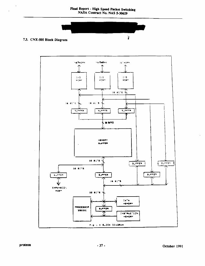
Final Report - High Speed Packet SwitchingNASA Contract No. NAS $-30629
7.3. CNX-500 Block Diagram
=.-mr :a
"/_" L
:_e, I
i.i:,L ..j_.-£ ;0 _L_.-5
fir
q-
16vr$
qt_OIv
s_rfEm
... l
tXD&_g. ::';
J_m_
32 It S
=aoc[SS:m
ZgOOO
3E • S
t ..--,a J
e'I Ij _:rt_
"Ivl,_CSav [
1
:,_i.m_,¢:. _=_ *vm_tv
_:." = I _3Pl_,N=r;; I - : • t<
\
proteon - 37 - October 1991

FinalReport- HighSpeedPacketSwitchingNASAContractNo.NAS5-30629
8. SummaryandConclusions
This study has provided many significant findings and performance improvements which were applied to the
development of a successful, productized router. The culmination of this effort occurred at the recent Harvardbenchmarking tests organized by Scott Bradner. At those tests, the router's forwarding rate was measured atgreater than 28,000 packets per second.
The router running at the Harvard tests was based on the released hardware and software being delivered under
this contract, and included certain performance optimizations which have not been through the standard ProteonQuality and Assurance program.
The router being delivered under this contract consists of the hardware that is currently being shipped toProteon's commercial customers as Release 11.0 of the CNX-500. Additionally, two sets of software will be
delivered. The first set is the software which ran at the Harvard tests. The second set is the production version
that is generally available from Proteon as part of Release 11.0.
A full set of user documentation will be included in the final delivery.
proteon - 38 - October 1991