for netview/aix version 3.0 - gdc netview/aix version 3.0.0 operation team core software gdc...
TRANSCRIPT

for NetView/AIXVersion 3.0.0
Operation
TEAM Core Software
GDC 058R720-I300-01Issue 1- June 1998
General DataComm

Warranty
General DataComm warrants that its equipment is free from defects in materials and workmanship. The warrantyperiod is one year from the date of shipment. GDC's sole obligation under its warranty is limited to the repair orreplacement of the defective equipment provided it is returned to GDC, transportation prepaid, within a reasonableperiod. This warranty will not extend to equipment subjected to accident, misuse, or alterations or repair not madeby GDC or authorized by GDC in writing. The foregoing warranty is exclusive and in lieu of all other warranties,express or implied, including but not limited to, warranties of merchantability and fitness for purpose.
Trademarks and PatentsGeneral DataComm, the General DataComm logo and the following are trademarks of General DataComm, Inc inthe United States and other countries: ACCULINE, ANALOOP, AUTOFRAME, BERT 901, DATACOMMSECURE-PAK, DATALOOP, DIGIDIAL, ENmacs, FASTPRO, FIRST RESPONSE, GDC, GDC APEX,GENERAL DATACOMM X-PRESS, GEN*NET, GEN*PAC, IMAGE*TMS, KILOMUX, LAN*TMS,MEGA*BRIDGE, MEGAMUX, MEGAMUX TMS, MEGANET, MEGASPLIT, MEGASWITCH, MEGAVIEW,NETCON, NETSWITCH, NMC, QUIKSHIPPERS, SERVI-CHECK, SERVI-SNAP, WINmacs.
ANALOOP and DATALOOP respectively are protected by U.S. patents 3,655,915 and 3,769,454. All other productsor services mentioned in this document are identified by the trademarks, service marks, or product names asdesignated by the companies who market those products. Inquiries concerning such trademarks should be madedirectly to those companies.
Copyright© 1998 General DataComm, Inc. All rights reserved.P.O. Box 1299, Middlebury, Connecticut 06762-1299 U.S.A.
This publication and the software it describes contain proprietary and confidential information. No part of thisdocument may be copied, photocopied, reproduced, translated or reduced to any electronic or machine-readableformat without prior written permission of General DataComm, Inc.
The information in this document is subject to change without notice. General DataComm assumes no responsibilityfor any damages arising from the use of this document, including but not limited to, lost revenue, lost data, claims bythird parties, or other damages. If you have comments or suggestions concerning this manual, please write toTechnical Publication Services or call 1-203-758-1811.

..1-1
..2-5
..2-6
...2-6
...2
..2-7...
....2-8...
...2-9
.2-9
10
2-10
....3-2
...3-2
....3-4
...3
Table of Contents
Preface
1 Introduction
Overview .................................................................................................................................1-1Responsibilities of the TEAM Core ......................................................................................
2 Maps and Discovery
Overview .................................................................................................................................2-1Maps ........................................................................................................................................2-1
Circuit Map Creation ......................................................................................................
Map Integration .......................................................................................................................2-5
Discovery ..........................................................................................................................2-5Shelf Map..........................................................................................................................2-5
NetView SNMP Configuration .............................................................................................Database ..................................................................................................................................2-6
Shelf Map ................................................................................................................................2-6Startup...............................................................................................................................2-6
Shelf Map Synchronization ...........................................................................................Shelf Map Editing..........................................................................................................-7
TEAM Universe Submap ...............................................................................................Shelf Submap.................................................................................................................2-7
Background Images ......................................................................................................Symbol Types ................................................................................................................2-8
Rediscovery and Alarm Synchronization.............................................................................Manual Discovery ...................................................................................................................2-9
To Disable Auto-Discovery by Stopping Netmon...........................................................
To Disable Auto-Discovery by Turning Off NetView Polling ......................................2-
To Perform Manual Discovery .......................................................................................
3 Operations
Introduction .............................................................................................................................3-1Common Window Features.................................................................................................
Map Window Menu Bar Access ..........................................................................................Performance Menu Functions .............................................................................................
Front Panel........................................................................................................................3-4What Are You? ..............................................................................................................-6
GDC 058R720-I300

ii Table of Contents
. 3-7
.
3-8. 3-
. 3-9
.3-10
. 4-1
..4-2
4-24-3
.. 4-
.. 4. 4-6
. 4-6
. 4-6
. 4-
. 4-94-10
-114-12
4-12
. 5
..
5-2-2
5-3
. 5
. 5-5
Configuration Menu Functions .............................................................................................Maintenance.................................................................................................................... 3-7
SCM Configuration..........................................................................................................Shelf Configuration.........................................................................................................8
Miscellaneous (Misc) Functions ...........................................................................................Information ...................................................................................................................... 3-9
Alarm Severity ................................................................................................................3-9Front Panel Poll Rate .....................................................................................................
Note Pad......................................................................................................................... 3-11Power Supply Status............................................................................................................. 3-11
4 SCM Configuration
Introduction ............................................................................................................................ 4-1To Start SCM Configuration .................................................................................................
Configuration Procedure ......................................................................................................4-1Main SCM Configuration Window........................................................................................
Menu Selection Definitions .............................................................................................SCM Configuration Window Fields ................................................................................
Redundant SCM Options......................................................................................................4Trap Options........................................................................................................................... 4-5
Traps Supported.............................................................................................................-6Trap Generation Fields ...................................................................................................
Trap Destination Table ...................................................................................................Selected Entry Criteria....................................................................................................
SCM IP Routing Options ......................................................................................................8Fields................................................................................................................................ 4-8
SNMP IP Routing ...........................................................................................................SCM Community Name Options .........................................................................................
Community Name MIB Description.............................................................................. 4Configuration Procedures ..............................................................................................
Miscellaneous SCM Options................................................................................................
5 Shelf Configuration
Introduction ............................................................................................................................ 5-1
To Start Shelf Configuration .................................................................................................-1Configuration Procedure ......................................................................................................5-1
Shelf Configuration Window .................................................................................................Shelf Configuration Window Read-Only Display........................................................... 5
Shelf Timing........................................................................................................................... 5-3Shelf Timing Options.......................................................................................................
Button............................................................................................................................... 5-4Highway Allocation Status....................................................................................................-4
Highway Status Display..................................................................................................Button............................................................................................................................... 5-5
GDC 058R720-I300

Table of Contents iii
5-6
5-7
5-85-8
. 5-9-10
5-11
5-11
. 5-12
. 6-1
. 6-16-1
6-1
. 3-4
3-7
. 3-7
3-9
3-11
3-12
4-3
4-4
4-5
-8
11
-13
5-2
5-3
5-5
-6
LTU Highway Configuration .................................................................................................Buttons ............................................................................................................................. 5-7
Input Fields ...................................................................................................................... 5-7Check Box Matrix............................................................................................................
LTU Highway Configuration Procedure .........................................................................DSE Highway Configuration .................................................................................................
Button............................................................................................................................... 5-9Input Field........................................................................................................................ 5-9
Time Slot Assignment ....................................................................................................DSE Highway Configuration Procedure........................................................................ 5
Slot Service States ................................................................................................................ 5-10Slot:Line Status Display ................................................................................................
Desired Status Panel ......................................................................................................
Button............................................................................................................................. 5-12Status Change Procedure ..............................................................................................
6 Utilities
Universe Map Fault Menu Functions....................................................................................Poll Shelf.......................................................................................................................... 6-1
Set/Unset Time on Shelf .................................................................................................Firmware Download...............................................................................................................
Line Statistics Collector ......................................................................................................... 6-8
Set-up Procedure............................................................................................................0
Index
Figures
3-1 SCM Front Panel .........................................................................................................
3-2 What Are You? Window ..............................................................................................
3-3 Maintenance Window..................................................................................................
3-4 Alarm Severity Window...............................................................................................
3-5 Front Panel Poll Rate Window ...................................................................................
3-6 Power Supply Status Window ....................................................................................
4-1 SCM Main Configuration Window ..............................................................................
4-2 Redundant SCM Options Configuration Window .......................................................
4-3 SCM Trap Options Configuration Window .................................................................
4-4 SCM IP Routing Options Configuration Window ....................................................... 4
4-5 SCM Community Names Options Configuration Window........................................ 4-
4-6 Miscellaneous SCM Options Configuration Window................................................ 4
5-1 Shelf Configuration Window .......................................................................................
5-2 Shelf Timing Configuration Window...........................................................................
5-3 Highway Allocation Status Window ............................................................................
5-4 LTU Highway Configuration Window ........................................................................ 5
GDC 058R720-I300

iv Table of Contents
5-9
-11
6-3
6-6
6-7
6-9
-10
-12
5-5 DSE Highway Configuration Window.........................................................................
5-6 Slot Service States Configuration Window................................................................ 5
6-1 Firmware Download Window ......................................................................................
6-2 Firmware Download Task Queue Window..................................................................
6-3 Download History Window..........................................................................................
6-4 Line Statistics Collector Window.................................................................................
6-5 Statistics Collector Group Selection Window............................................................ 6
6-6 Line Statistics Status Window.................................................................................... 6
GDC 058R720-I300

Preface
ScopeThis manual describes how to operate the GDC TEAM Core Software applications. The TEAM software is a group of NetView applications that employ the Simple Network Management Pro-tocol (SNMP) to configure and control the operation of a wide variety of GDC equipment housed in SpectraComm shelves. The TEAM Core applications described in this book perform functions that extend beyond the scope of individual, product-specific TEAM applications, enabling the individual applications to function together in a coordinated and efficient manner.
TEAM applications, running on a workstation, communicate with the units they control and monitor through a SpectraComm Manager (SCM) card that occupies the SpectraComm shelf with those units. SCM Configuration, by which you determine how the SCM card carries out its function as the SNMP agent for units in its shelf, is a responsibility of the TEAM Core Software.
A number of TEAM applications are dedicated to the control of devices in the SpectraComm 5000 system. In that system multiple Data Set Emulator (DSE) cards perform DTE interface functions and employ data highways on the SpectraComm shelf backplane to exchange data with a Line Terminating Unit (LTU) card responsible for network interface functions. The TEAM Core Software Shelf Configuration functions are responsible for configuring the operation of the data highways employed by the SC 5000 system.
This manual assumes a working knowledge of NetView.
Revision HistoryThis is the initial issue of the manual for Version 3.0.0 of the TEAM Core software.The immediately preceding version was 1.7.0.
This software has been tested to be Year 2000 Compliant in accordance to GDC ENG-STD-003. Check GDC's web site at http://www.gdc.com for the latest year 2000 information.
Version 1.7 differed from 1.6 through addition of the Alarm Severity assignment function and support for the TEAM 7624 application.
Version 1.6 was the first TEAM Core software to operate in the NetView environment. Earlier versions operated exclusively in an HP OpenView environment. NetView and OpenView are functionally identical, though they differ in some menu terminology.
OrganizationThis manual has six chapters. The information is arranged as follows:
• Chapter 1 - Introduction describes the TEAM Core applications.
• Chapter 2 - Maps and Discovery describes the process by which the TEAM Core applications discover and map equipment that is subject to TEAM software control.
• Chapter 3 - Operation provides directions for accessing the smaller individual applications that are responsible for the TEAM Core functions. It describes how to access
GDC 058R720-I300

vi Preface
the functions from a shelf map window menu bar, and from the Select menu of an SCM front panel display. The chapter provides full descriptions of the TEAM Core applications that display read-only windows, of the Line Statistics Collector application, of the Firmware Download function, and of the Alarms Severity function. It provides access information for the applications that display read/write windows and require greater operator interaction.
• Chapter 4 - SCM Configuration provides instructions for accessing the SCM Configuration application and using it to set IP addressing and routing in the SCM.
• Chapter 5 - Shelf Configuration provides instructions for accessing the Shelf Configuration application and using it to set shelf timing and data highway assignment parameters in an SC 5000 system.
• Chapter 6 - Utilities provides instructions for the Poll Shelf, Set/Unset Shelf Time, Firmware Download, and Line Statistics Collector functions.
Document Conventions
Level 1 paragraph headers introduce major topics.
Level 2 paragraph headers introduce subsections of major topics.
Level 3 paragraph headers introduce subsections of secondary topics.
This typewriter font shows output that is displayed on the screen.
This bold font shows specific input that you type at the keyboard.
This bold italicized font shows variable input that you type at the key-board.
Publication NumbersGDC publication numbers (e.g., GDC 058R720-I300) are used to track and order technical man-uals. Publication numbers use the following format:
GDC NNNRnnn-000-xx or GDC NNNRnnn-Vnnn-xx
• NNN identifies the product family (e.g. TEAM)
• R denotes a technical publication
• nnn number assigned by Technical Publications
• 000 identifies a hardware product and does not change
• Vnnn V number indicates a software product, and corresponds to the version/revision
• xx two-digit issue number appears only on the cover; changes when a hardware manual is revised or when a manual is reprinted for some other reason
A new Software Version is always Issue 1. Other specialized publications such as Release Notes or Addenda may be available depending on the product.
Notes present special instructions, helpful hints or general rules.
NOTE
GDC 058R720-I300

Preface vii
anage, h your
ervice
t avail-
basic nd are
Service and SupportGeneral DataComm is committed to providing the service and support needed to install, mand maintain your equipment. For information about service programs or for assistance witsupport requirements, contact your local Sales Representative or call General DataComm Sat the 24-hour, toll-free number listed below.
• in the U.S. dial 1-800-243-1030
• outside the U.S. dial 1-203-598-7526
Be ready with the site name and phone number, and a description of the problem. The nexable support representative will promptly return your call.
Hands-on training courses are provided by GDC Educational Services. Courses range fromdata communications, modems and multiplexers, to complex network and ATM systems ataught in Connecticut or at a customer location. To discuss educational services or receive a course schedule, call 1-800-243-1030 and follow the menu instructions.
GDC 058R720-I300

viii Preface
ta and plane h
em bles to
unit at .
ns. here
Glossary of Terms
Backplane Data Highway
High speed bus built into the SpectraComm Shelf backplane to support the exchange of datiming signals between a line terminating unit and a group of data set emulators. The backcontains four data highways. Data traffic on the highways takes place in timeslots, each of whicis equivalent to one DS0 at the LTU network interface. Each data highway consists of 32 timeslots for compatibility with an E1 LTU. Timeslots 1 through 24 are used when the systcontains a T1 LTU. The data highways of two shelves can be connected by daisy-chain casupport a total of 32 shelf slots.
Data Set Emulator (DSE)
Term for the units in the SpectraComm 5000 system that provide DTE interface functions. Each DSE is designed to be compatible with a GDC device that can be installed as a standalonea remote site. An SC 5553 DSE, for example, is compatible with a remote NMS 553 DSU
Line Terminating Unit
Term for the unit in the SpectraComm 5000 system that provides network interface functioThe T1 LTU for the SC 5000 system is the SC 5001 LTU, and the E1 LTU is the SC 5002. Tcannot be a T1 LTU and an E1 LTU in the same shelf.
GDC 058R720-I300

quip-
ard to y chain g point sses
an-
to the alarm
d
624
e i
1 Introduction
OverviewThis chapter describes the core elements of GDC TEAM management applications for ement that operates in a SpectraComm shelf. These TEAM Core applications operate in conjunc-tion with the SpectraComm Manager (SCM) card that resides in each shelf.
The bus structure incorporated in the SpectraComm shelf backplane enables the SCM cact as a shared management agent for compatible components installed in the shelf. Daiscables can extend the backplane bus to a second shelf. The use of the SCM as a clearinfor SNMP management activity conserves on the number of Internet Protocol (IP) addrerequired for management functions.
The SCM performs all communication functions between the workstation that runs the magement application and the equipment being managed. It receives SNMP Set and Get com-mands from the application and sends equivalent commands to the selected unit via thebackplane. It also generates Traps, which are unscheduled, unsolicited messages sent management application in response to events at the unit, particularly the occurrence ofconditions.
Applications that employ the TEAM core include
• TEAM V.34 for control of GDC V.F 28.8 modems
• TEAM Dual V.34 for control of GDC Dual V.34 modems
• TEAM 521 for control of GDC SC 521 DSUs
• TEAM SC 553 for control of GDC SC 553 DSUs
• TEAM 5000 applications – TEAM 5001, TEAM 5002, TEAM 5520, TEAM 5553, anTEAM 5034 for control of the corresponding devices in a SpectraComm 5000 system
• TEAM 7000 applications – TEAM 7001, TEAM 7002, TEAM 7616 for control of thecorresponding devices in a UAS 7000 system and TEAM 7624 for control of GDC 7NIU/DIUs
Responsibilities of the TEAM CoreThe TEAM core application consists of functions that relate directly to the operation of thSCM, such as its configuration; and of NetView control functions that are shared by the dffer-ent TEAM applications dedicated to the control of specific equipment types.
GDC 058R720-I300

1-2 Introduction
uip-lica-n and
per-s that ifica-
s (“data
ns,
The shared NetView functions are Discovery, by which the application determines what eqment subject to its control it is able to communicate with; and Mapping, by which the apption displays the equipment it has discovered arranged into groups determined by functiolocation.
When the TEAM core applications are used with TEAM 5000 applications to control the oation of a SpectraComm 5000 system, the core applications are responsible for functioncoordinate the operation of components within the system. These functions include spection of timing sources to be used by the system components and assignment of data pathhighways and timeslots”) on the backplane bus.
The TEAM 7000 applications employ TEAM Core for the Discovery and Mapping functiobut not for backplane coordination functions.
GDC 058R720-I300

Sim-jects ored very.
ess, it en-
a bur-is the h the ppli-
uto-outing
ation
ions, ions ality
p is icate e shelf sso-hows more creation
2 Maps and Discovery
OverviewDiscovery, which searches for devices on the network, is integrated with the NetView IP nodediscovery application. Once an SCM card is discovered, Discovery polls the SCM using theple Network Management Protocol (SNMP) and uses the information it gathers to build obin the NetView Windows (OVW) database. The objects represent cards in the shelf monitby the SCM. These are monitored by the SCM and discovered (through polling) by Disco
The default state is for the TEAM Core application to perform auto-discovery. In this procthe application polls each new device it encounters to identify those that are SCMs. Whencounters an SCM it conducts further polling to construct the shelf submap.
There can be circumstances in which the data traffic required for auto-discovery becomesden on the communication network, reducing the throughput of payload data. When that case you may decide to suspend auto-discover, either by turning off NetView polling througUniverse submap Options menu or by disabling the netmon function of the TEAM Core acation.
The TEAM Core application includes provisions for performing manual discovery when adiscovery is disabled. In the manual discovery process the application requests only the rtables of the specified unit.
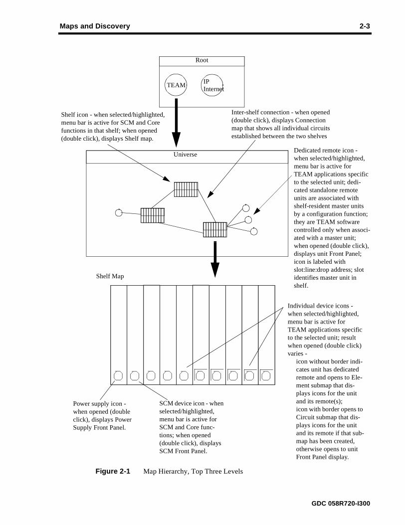
MapsAccess to the TEAM software applications takes place through a hierarchy of maps that progressfrom general to specific, each presenting a more detailed view of a smaller part of the communications system. Figures 2-1 and 2-2 on the following pages illustrate characteristics of the maps to support the descriptions that appear below.
Root map – the top of the hierarchy, contains the TEAM icon and the IP Internet icon. TheTEAM icon is the initial point of access to all applications that operate in conjunction with the TEAM core. The IP Internet icon provides access to a map of the workstation’s communicenvironment.
The Root map can also contain a TEAM Standalone icon if there are standalone applicatsuch as TEAM 553S or TEAM 540, installed on the workstation. The standalone applicatand the devices they control are self contained. They do not employ shared core functionand they communicate with the workstation individually, not through an SCM card.
Universe map – is displayed by opening the TEAM icon in the Root map. The Universe macomposed of shelf icons, one for each SCM-equipped shelf the workstation can communwith. The Universe map also displays dedicated remote devices, each joined by a line to ththat contains its master unit. Some shelf-resident devices, such as the SC 521 DSU, can be aciated by a configuration function with a dedicated remote device. The Universe map also slines joining shelves that have been associated with each other by the creation of one or Circuit submaps. Standalone remotes that have been associated with shelf devices by the of Circuit submaps also appear in the Universe map.
GDC 058R720-I300

2-2 Maps and Discovery
the ected.
Add f map
ent . The annot cre-aster
rse select-utton
e win- icons
e nds of an be
If the ave to
Shelf map – opening a shelf icon in the Universe map displays the corresponding Shelf map, which is a pictorial representation of the shelf and the individual devices installed in it. Inshelf picture, each TEAM compatible device has an octagonal icon by which it can be sel
Element map – if a device has one or more dedicated remotes associated with it by the Remote or Wake Up Remote Configuration function, its device icon appears on the Shelwithout a square border around it. Double clicking on the borderless icon opens the Elemmap, which represents the link between the master device in the shelf and its remote(s)link can be point-to-point or multipoint. The remotes in an Element map are devices that ccommunicate independently with the TEAM controller workstation. The Element map is ated automatically by the configuration function that associates the remote(s) with the munit.
Connection map – is opened by means of the line that connects two shelves in the Univemap. The map can be opened by double clicking the left mouse button on the line, or by ing the line with a single click of the left mouse button and then pressing the right mouse band selecting Open Symbol from the resulting menu. A Connection map displays, in ondow, all the circuits that exist between the two shelves. Each circuit is represented by thefor its devices, connected to each other by lines that represent the communication path.
Circuit map – is a user-created map that displays the link between two devices. The purposof the map is to provide a convenient point of access for launching applications at both ea link. If the same shelf resident device type is at both ends of the link, the two devices cselected together so that applications for both are launched by a single menu selection.circuit map is of a shelf resident device linked to a standalone device, their applications hbe launched separately.
GDC 058R720-I300
Maps and Discovery 2-3
Figure 2-1 Map Hierarchy, Top Three Levels
Root
TEAMIPInternet
Universe
Shelf icon - when selected/highlighted, menu bar is active for SCM and Core functions in that shelf; when opened (double click), displays Shelf map.
Dedicated remote icon - when selected/highlighted, menu bar is active for TEAM applications specific to the selected unit; dedi-cated standalone remote units are associated with shelf-resident master units by a configuration function; they are TEAM software controlled only when associ-ated with a master unit; when opened (double click), displays unit Front Panel; icon is labeled with slot:line:drop address; slot identifies master unit in shelf.
Inter-shelf connection - when opened (double click), displays Connection map that shows all individual circuits established between the two shelves
Shelf Map
SCM device icon - when selected/highlighted, menu bar is active for SCM and Core func-tions; when opened (double click), displays SCM Front Panel.
Individual device icons - when selected/highlighted, menu bar is active for TEAM applications specific to the selected unit; result when opened (double click) varies -
icon without border indi-cates unit has dedicated remote and opens to Ele-ment submap that dis-plays icons for the unit and its remote(s);icon with border opens to Circuit submap that dis-plays icons for the unit and its remote if that sub-map has been created, otherwise opens to unit Front Panel display.
Power supply icon - when opened (double click), displays Power Supply Front Panel.
GDC 058R720-I300

2-4 Maps and Discovery
Figure 2-2 Map Hierarchy, Connection and Circuit Submaps
Connection
Connection map - displayed by opening (double clicking) inter-shelf connection in the Universe map; this map contains all circuits configured between two shelves; it is created automatically when the first circuit is configured, and auto-matically adds new circuits as they are configured.
Device icons - when selected/highlighted, menu bar is active for TEAM applications specific to the selected unit; multiple icons of the same type can be selected in order to launch multiple application win-dows simultaneously; when opened (double click) dis-plays unit Front Panel.
Circuit
Circuit map - displayed by opening (double click-ing) device icon in the Shelf map; this map is user created to provide convenient access for opening applications at both ends of a link simultaneously. A Circuit map should not be created for devices that are associated by an Add (or Wake Up) Remote configuration function.
GDC 058R720-I300

Maps and Discovery 2-5
f thosee, youat de-
e map.r end.
se the select-
Copy:
enu.e line
i.e.,
lays
onse
Circuit Map Creation
Unlike the other maps that display portions of the TEAM universe, Circuit maps are created by the user. The procedure for creating a Circuit map:
1. Open the two maps that contain the ends of the circuit to be mapped. At least one otwo maps must be a Shelf map. If the Circuit map is to contain a standalone devicneed to open the TEAM Standalone icon in the Root map to access the icon for thvice.
2. Select the shelf resident device that is to be one end of the circuit and the basis of thIf both ends of the circuit are to be shelf resident devices, you can start with eitheIf one end is a standalone device, you must begin with the shelf resident device.
3. Select Create Circuit Submap... from the menu bar Configuration menu. In responapplication creates and displays the map, which contains one icon to represent theed device.
4. Select the icon for the device that is to be the second end of the link, and select From This Submap from the menu bar Edit menu in that device’s map.
5. Click the mouse in the new Circuit map and select Paste from its menu bar Edit mWhen the second icon is pasted into the map, the application automatically adds ththat represents the connection between the two devices.
MAP IntegrationThe following processes are involved in map integration:
Discovery
• Discovers TEAM-compatible hardware systems in the network and their contents, the cards that they contain
• Creates the system and equipment objects in the OVW database
Shelf Map
• NetView Map application ‘gets’ the topology view from the OVW database and dispnetwork topology in an open map.
• Updates the topology view (Add/Delete/Modify Systems, Equipment, Status) in respto traps received.
• Creates and maintains (updates) shelf background images.
• Creates images to reflect the shelf contents.
The application permits any two devices to be specified as the ends of a circuit. The user is responsible for making sure that the Circuit map accurately represents a real communication link.
Do not create a Circuit map for master and dedicated remote devices that are associated by means of an Add (or Wake Up) Remote configuration function. The configuration function automatically creates an Element map for those devices.
NOTE
GDC 058R720-I300

2-6 Maps and Discovery
t nable
t
Net-
deals
ying
e In-
iew
f Map maps ork
ing this ccess hile
tions ed
ology
NetView SNMP ConfigurationThe Community Names (both Read and Write) set in NetView SNMP Configuration musmatch the configured Community Names on the SCM. If they are incorrect, Discovery is uto poll or update the SCM.
The SNMP Configuration selection appears in the Options menu of the NetView menu bar thaappears at the top of all map windows.
DatabaseThe Shelf Map function creates the following types of database objects:
• Root Object
• SpectraComm Shelf Object
• Objects for different types of cards
• Objects for card interfaces
• Remote device objects
The Root object is the parent object of the TEAM software. The Root symbol is created fromthis object and all Submaps extend from this symbol. There is only one Root object per View database.
The SpectraComm Shelf object serves as a logical addressing entity for SCM cards. Thiswith multiple IP addresses for the same shelf.
Shelf Map The Shelf Map function is an integrated application under NetView, responsible for displaobjects in NetView. It displays the network in a hierarchy of submaps, multiple levels deep:
• Universe Submap — contains the SpectraComm shelves found by Discovery
• Shelf Submap — displays all the devices in a shelf
• Interfaces Submap — displays all the interfaces for a selected device in a shelf. Thterfaces Submap for a master device (the local, or central site, unit controlled by the TEAM software) also contains the remote unit(s) associated with the master.
Startup
The Shelf Map function starts automatically when OpenView Windows starts. As an NetVprogram, it runs only when executed by NetView.
Shelf Map Synchronization
The Shelf Map function enters its synchronization phase when it is started. While the Shelis synchronizing, NetView displays a Synchronizing message on the status line of the subdisplayed. During synchronization, the Shelf Map function creates symbols for new netwobjects to update the Submaps that use the database. It also updates alarm status. Durtime the Shelf Map function cannot respond to some NetView requests and you cannot asome functions. For example, NetView restricts you from deleting symbols and objects wan application is synchronizing. Also, the Shelf Map does not appear in the list of applicaon dialog boxes until it completes its initial synchronization. When the Shelf Map is finishwith synchronization it enters a mode where it handles incoming NetView events and topchanges.
GDC 058R720-I300

Maps and Discovery 2-7
take a more . A
re are
ferent
to the
from
symbol ice it
Sub-
tem ts Cat-
Shelf
a table
ting a
s the
prop- re-
The Shelf Map function also displays the synchronizing message during operations that long time, such as updating a shelf graphic. See the shelf background graphics topic forinformation. The Shelf Map synchronizes in conjunction with other NetView applicationssynchronizing message may result from any one of the applications synchronizing.
Shelf Map Editing
The Shelf Map supports map edits accomplished through the NetView user interface. Theseveral ways in which you can modify the map through the user interface including: add, delete and cut/paste symbols. As mentioned above, these operations are not accessible during map synchronization.
Addition of symbols includes both icon and connection symbols that are accessed via difmenu items in NetView. The Shelf Map function does not accept additions of icon or connec-tion symbols on the application plane of the map. However, you can to add any symbol user plane.
The Shelf Map function supports the deletion of symbols from the map. Deleting an objectthe map also deletes it from the SCM tables.
The cut and paste operations are supported by Map. However, the result of the paste is a in the user plane of the map. The status of the symbol is kept synchronized with the devrepresents.
Refer to the NetView User’s Guide for additional detail.
TEAM Universe Submap
The TEAM Universe Submap is accessed through the Root symbol in the NetView Rootmap. It contains a symbol for each SpectraComm Shelf discovered. There is only one Universe Submap on each map.
You can modify them using the Describe/Modify Object Dialog Box. The label of the sysis the text name as assigned in the system configuration application. Events in the Evenegory application reference the shelf selection name as the source of the event.
Shelf Submap
The Shelf symbols on the TEAM Universe Submap provide access to Shelf Submaps. ASubmap contains a symbol for each card in the corresponding shelf.
The SCM card proxies SNMP messages to the other cards in the shelf. It also maintains of all cards in the Shelf.
You can execute applications by selecting a symbol in the Shelf Submap and then selecmenu item that corresponds to an application.
Slot DeletionThe SCM discovers each card in a shelf and the remotes linked to those cards, and holdinformation until it is deleted by the TEAM software. Physically removing a card from a shelf or disconnecting a device from the system does not delete it from the Shelf Submap. Toerly remove a card or other device from the system you must both physically remove it andmove it from the SCM Node Table.
Exercise care in deleting symbols from the shelf map. If a device symbol is de-leted in error, power to the device has to be cycled before the device can be dis-covered and its symbol restored to the map. NOTE
GDC 058R720-I300

2-8 Maps and Discovery
e, thatns dis-
tView with
tion
bmap e
Each l rep-l is an n the
in when card. tation on.
ap-he IP
SCM lity
vered
Removal procedure:
1. Physically remove the device from the system. In the case of a central site devicmeans removing the card from the shelf. In the case of a remote device, that meaconnecting it.
2. At the TEAM workstation, select the shelf from the Shelf Submap.
3. Select the device you are deleting, pull down the Edit menu, and select Delete.
Background Images
The Shelf Map function can represent the SpectraComm Shelf and its contents in an Nebackground image. The image is synchronized with the current shelf configuration and displaysthe shelf with all SCM cards in the proper locations. Shelf Submap symbols are aligned their corresponding card image in the background image.
You can set this capability using the Map Configuration Dialog Box. The default configurais to enable background graphics.
Symbol Types
The Root symbol is your access to the system in NetView. It is the highest level in the Suhierarchy. This symbol is created in the NetView Root Submap. You can access the UniversSubmap by double clicking on this symbol.
The Shelf symbol is the logical representation of the SpectraComm Shelf in the Network.physical shelf on the network has a corresponding Shelf symbol in the Map. This symboresents more than the SCM card, it represents all the cards in the shelf. The Shelf symboaccess point to the Shelf Submap. You can open the Shelf Submap by double clicking osymbol.
The SCM symbol represents the SCM card in the SpectraComm Shelf. There are two placesNetView where this symbol is found. IP Map creates this symbol in the Internet Submap discovered by netmon to be an SCM. This symbol represents the IP Map view of the SCMThe Shelf Map function creates the SCM symbol on the Shelf Submap. This is a represenof the SCM card within the shelf. The symbol is built using the object discovered by netmThe status source for this symbol is set to Compound (Propagate).
SCM MisidentificationDuring set up of a new system, it can occur that NetView Discovery runs before the TEAMplication software is installed. If an SCM is discovered when this happens, it is added to tsubmap as a generic object.
When the application software is in place, the presence of the generic object prevents thefrom being discovered and correctly identified. While an SCM is misidentified its functionais not available to the TEAM applications.
If this occurs, delete the SCM generic object and ping the device so that the SCM is discocorrectly and identified by an SCM object.
GDC 058R720-I300

Maps and Discovery 2-9
the
ents and pri-
ruct- con-
is op- task ns of
ocal
ing
ginal
ad
e by
Rediscovery and Alarm SynchronizationYou can run Synchronization on-demand by selecting Poll Shelf from the Fault menu in NetView menu bar that appears at the top of map and submap windows.
The time it takes the Poll Shelf application to run varies according to the number of elemin the shelf. In environments, such as DDS I, that use the same channel for both primarymanagement data the Discovery and Alarm Synchronization functions can interfere withmary data flow while they are running.
Manual DiscoveryManual Discovery enables you to identify an SCM to the TEAM application, thereby insting the application to poll the SCM and construct a shelf submap for it and the devices ittrols. This process is not required while the application is performing auto-discovery.
If auto-discovery is rendered undesirable by the size of network in which the application erating, it can be disabled within the TEAM Core application itself by stopping the netmonthat Shelf Discovery requires to operate. It can also be disabled through NetView by meathe Universe submap Options menu. Both methods are described below.
To Disable Auto-Discovery by Stopping Netmon
Within the TEAM application, operation of the auto-discovery process is governed by a LRegistration File (LRF) called discover.lrf that is located in the directory /usr/OV/lrf. To disable auto-discovery by turning off netmon you need to modify that file by carrying out the followsteps:
1. Open a shell tool on your workstation.
2. Stop the Shelf Discovery process by typing
/opt/OV/bin/ovstop shelf_discovery
3. Make a backup copy of the discover.lrf file so that it can be reloaded later in its oriform if needed.
4. Load the discover.lrf file into an editor so that you can modify it.
5. Locate the following two lines in the file
/opt/OV/bin/shelf_discovery:
OVs_YES_START:trapd,ovwdb,netmon::OVs_WELL_BEHAVED:15
6. Delete ,netmon from the second line and save the file. The two lines should now re
/opt/OV/bin/shelf_discovery:
OVs_YES_START:trapd,ovwdb::OVs_WELL_BEHAVED:15
7. To update the process configuration, run NetView Add Object on the discover.lrf filtyping
If the NetView windows are exited while either of these windows is open, it re-mains open until you close it manually.
NOTE
GDC 058R720-I300

2-10 Maps and Discovery
w-
maticoll-
ropri-iscov-
as the
alk” sure
ub-
dress.
s the
/opt/OV/bin/ovaddobj /usr/OV/lrf/discover.lrf
8. Restart the Shelf Discovery process by typing
/opt/OV/bin/ovstart shelf_discovery
To Disable Auto-Discovery by Turning Off NetView Polling
The auto-discovery process is part of the larger Status Polling procedure carried out by the Net-View software. To disable auto-discovery by controlling NetView polling, carry out the folloing steps:
1. Display the Universe submap.
2. From the Options menu, select Topology/Status Polling.
3. In the resulting dialog box deselect either Polling Master Switch, to suspend all autopolling by the NetView software, or New Mode Discovery Switch, to suspend only ping for the discovery process.
4. Dismiss the dialog box.
To Perform Manual Discovery
Before you can perform manual discovery on an SCM it must be configured with the appate community name and you must be able to communicate with it. To perform manual dery carry out the following steps:
1. From the Options menu, select SNMP Configuration and make sure that the SCM hproper Community Configuration.
2. Make sure you can communicate with the SCM by pinging it and issuing an “snmpwcommand. If this does not work, check the routing tables in the workstation to makethere is a route available to the SCM.
3. Display the IP submap of the segment to which the SCM is connected.
4. From the Edit menu, select Add Objects.
5. In the resulting window select the “Computer” symbol class.
6. Modify the symbol by using the middle mouse button to drag the “SCM” Symbol Sclass onto it on the IP submap.
7. In the Add Objects dialog box, enter the label assigned to the SCM.
8. Set the IP Map Object Attributes. Be sure to enter both the hostname and the IP ad
When the process is completed, the Shelf Discovery application polls the SCM and drawshelf topology based on the information it receives from the SCM.
If a valid hostname is not available, enter the IP address of the SCM in the Hostname field.
NOTE
GDC 058R720-I300

voted
lect er on
le nel
he enu
n in
nly
from
s two d by aph e in
d
3 Operations
IntroductionThe TEAM core software application consists of a group of smaller applications, each deto a specific aspect of controlling or monitoring functions administered by a SpectraCommManager (SCM) card. The following functions make up the TEAM core applications:
Front Panel – displays the SCM front panel to provide LED monitoring and Sebutton menu access to most other core functions; accessible undPerformance in the shelf submap menu bar or by double clickingshelf submap SCM icon
What Are You? – displays read-only What Are You information window; accessibunder Performance in shelf submap menu bar and SCM front paSelect button menu
SCM Configuration – displays Configuration windows for configuring the SCM with IPaddressing and routing; accessible under Configuration in both tshelf submap menu bar and the SCM front panel Select button m(this function is identified simply as Configure in menus)
Maintenance – displays Maintenance window by which you can enable/disablealarm scan and set time and date; accessible under Configuratioshelf submap menu bar and SCM front panel Select button menu
Shelf Configuration – displays Shelf Configuration windows for configuring backplanedata highway and timing parameters that are required for the operation of an SC 5000 system; accessible under Configuration oin Universe map menu bar
Information – displays read-only Information window; accessible under Misc inUniverse map menu bar and shelf submap menu bar, accessible the SCM front panel display by double clicking on the GDC logo
Power Supply Status – displays a generic power supply front panel picture that containpower usage indicators. One shows the number of Watts requirethe SCM-managed devices in the shelf, the other shows a bar grrepresentation of that requirement as it compares to the wattageavailable in the shelf. This display is accessible under Performancthe shelf submap menu bar when the power supply icon is highlighted, or by double clicking on the power supply icon in theshelf submap.
This chapter fully describes the Front Panel, What Are You, Maintenance, Information, anPower Supply Status functions. The two configuration functions, because of their greatercomplexity, are each covered in chapters of their own: Chapter 4, SCM Configuration and Chapter 5, Shelf Configuration.
GDC 058R720-I300

3-2 Operations
ber
l
le
ight. e w.
at s.
cting
ve by s.
e s the
her
tend
Common Window FeaturesEach TEAM application you select opens an on-screen window in which to operate. A numof features are common to many of the windows:
Triangle button – in the title bar (present only when TEAM software is operating on a Sun workstation); reduces the window to an icon when you click on it. Doubleclicking on icon restores the window. This button appears on the top levewindow for each application.
Title bar – identifies the specific TEAM application running in the window; for exampSCM Configuration or DSE Highway Configuration
Menu bar – always contains the selections File, on the far left, and Help, on the far rFile menu always contains the selection Exit, by which you can dismiss thwindow; some window File menus contain selections special to the windoHelp menu provide access to information concerning the window. Some windows have additional menu bar selections.
The menu bar appears on the top level window for each application.
Name field – identifies the SCM the application is currently connected to by displaying theuser-configured shelf name, followed by the SCM slot number.
Descriptions in this manual of the individual TEAM applications identify window features thare specific to the applications, such as selections in the menu bar and menus, and button
Map Window Menu Bar AccessYou can access TEAM core application functions from the menu bar in two NetView map windows: the TEAM Universe map by selecting on a shelf icon, or a shelf submap by seleon an SCM icon.
There is a significant difference in the two forms of access: from the Universe map you haaccess to the Firmware Download function and to the Shelf Configuration functions required an SC 5000 system. The shelf submap does not provide access to either of those function
The first of the two following tables illustrates how the TEAM core application functions ararranged on the menu bar at the top of the TEAM Universe Map window. The second showfunctions that appear on the menu bar of a shelf submap. The tables show only the menuselections for the TEAM core applications. Map window menus also include selections in addition to those that apply to TEAM core because the window also provides access to otapplications.
You must select the shelf or SCM you intend to work with before you open the menu you into use. Select by clicking the mouse on the appropriate icon.
The menu item Agent Templates, which appears under Misc in the menu listings on the next page, does not apply to SCM-based applications that employ the TEAM Core software. The use of that function is therefore not documented in this manual.
Its functionality is employed by standalone TEAM application products such as TEAM 540 and TEAM 553. The Agent Templates function is documented in the manuals for those products.
NOTE
GDC 058R720-I300

Operations 3-3
TEAM Universe Map menus:
Shelf map menus (with SCM selected):
Menu Bar Menu Selections
Performance
Line Statistics...
Configuration
Firmware Download...
Maintenance...
Shelf Configuration...
Configure...
Fault
Poll Shelf...
Set Time on Shelf...
Unset Time on Shelf...
Misc
Agent Templates...
Information...
Front Panel Poll Rate...
Menu Bar Menu Selections
Performance
Front Panel...
What Are You...
Configuration
Configure...
Maintenance...
Misc
Agent Templates...
Information...
Front Panel Poll Rate...
Note Pad
GDC 058R720-I300

3-4 Operations
d Note Front
anel
click
The Performance menu Front Panel selection, and the Misc menu Front Panel Poll Rate anPad selections do not appear in the menus available through the Select button of the SCMPanel display window. All other valid selections in the shelf submap menus correspond toselections in the Select button menus.
Performance Menu FunctionsFront Panel
The SCM Front Panel display window (See Figure 3-1) provides a graphical interface to a selected SCM card. You can launch a Front Panel in either of two ways:
• select the unit you intend to work with in the NetView Map window, then select Front Pfrom the Performance menu for that window
• display the shelf sub-map that includes the unit you intend to work with, then double the mouse on the slot icon for the unit.
Figure 3-1 SCM Front Panel
GDC 058R720-I300

Operations 3-5
ition, utton. s field Help
nit. dark
ent ns
ent ns
e
trols.
nt
e olor
,
w the
he rest
The application responds by displaying a window that depicts the SCM front panel. In addthe bottom of the Front Panel display contains a Select button, a status field, and a Help bThe Select button provides access to the TEAM application menus for the SCM. The statudisplays information on communications between the application and the SCM card. The button displays help information concerning the Front Panel display.
The LEDs shown in the display reflect the states of the actual indicators on the physical uUnless otherwise noted in the following list, an LED appears bright green to indicate On orgreen to indicate Off. An LED that displays transitions does so by a two-headed arrow superimposed on the bright green LED.
SCM Front Panel display LEDs:
SD LAN – Send Data LAN, indicates transitions while the SCM is sending managemdata through its LAN port to the workstation that runs the TEAM applicatio
RD LAN – Receive Data LAN, indicates transitions while the SCM is receiving management data through its LAN port from the workstation that runs theTEAM applications
SD WAN– Send Data WAN, indicates transitions while the SCM is sending managemdata through its WAN port to the workstation that runs the TEAM applicatio
RD WAN– Receive Data WAN, indicates transitions while the SCM is receiving management data through its WAN port from the workstation that runs thTEAM applications
NR – Network Response, indicates transitions while the SCM is receiving management data responses on the shelf backplane from a device it con
ND – Network Data, indicates transitions while the SCM is sending managemedata on the shelf backplane to a device it controls
INS – In Service
ON – Power OnTM – Test Mode, bright red while the SCM performs it Power On Test sequence,
otherwise dark red
ALM – Alarm, dark red while the are no alarm conditions in the SCM; indicates thpresence of alarm conditions by changing color. The LED indicates by its cthe category of the current highest priority alarm: orange for a major alarmyellow for a minor alarm, green for an informational alarm.
The application can be set to poll the SCM so that the LEDs in the Front Panel display shocurrent states of the LEDs on the physical unit.
The Select button, at the bottom of the Front Panel display provides access to menus for tof the TEAM core application functions. The table on the following page shows the arrangement of the Select button menus. It differs somewhat from the arrangement on the Map window menu bar.
GDC 058R720-I300

3-6 Operations
le shot
d or a
ont
What
The two Poll selections in the Select button menu determine – for the current session – when theapplication is to collect new information from the SCM to update the Front Panel window:
• Selecting Demand Poll causes an immediate update of the display.
• Auto Poll enables you to select updates at 15, 30, or 60 second intervals, or to disabautomatic polling. If you select Disable, the Front Panel window displays a static snapof the LED states as they were at the last poll, either when the window was launchesubsequent Demand Poll.
Each time the Front Panel display is opened, its initial polling rate is determined by the FrPanel Poll Rate selection of the NetView map window Misc menu.
The menu selection Exit dismisses the Front Panel window when you click on it.
What Are You?
You can launch the TEAM What Are You? application from the shelf submap Performance menu or the front panel Select button Performance menu. The application displays the read-onlyAre You? window for the selected SCM (See Figure 3-2).
Select Button Menu Selections
Performance
What Are You?...
Configuration
Configure...
Maintenance...
Demand Poll
Auto Poll (*)
15 seconds
30 seconds
60 seconds
Disable
Exit * Displays Off or poll interval
GDC 058R720-I300

Operations 3-7
M
)
enu ance
r Off. e time ations.
Figure 3-2 What Are You? Window
The What Are You? window displays the following information concerning the selected SCcard:
Software Revision – identifies the revision level of the SCM operating software
Boot S/W Revision – identifies the revision level of the SCM boot software
MIB Version – identifies the revision level of the Management Information Base (MIBfiles that enable SNMP control of the SCM card
Configuration Menu Functions
Maintenance
You can launch the TEAM Maintenance application from the shelf submap Configuration mor the front panel Select button Configuration menu. The application displays the Maintenwindow for the selected SCM (See Figure 3-3).
Figure 3-3 Maintenance Window
The Maintenance window displays the state of the SCM Alarm Scan function, either On oIts Edit menu provides the means of controlling the Alarm Scan. It also enables you to set thand date in the SCM. The SCM uses time and date to identify alarms and other communic
GDC 058R720-I300

3-8 Operations
ose
tified ar and
ap figure
on
lf
hich
Maintenance Window Menus
The Maintenance window has File, Edit, and Help in its menu bar.
The File menu contains only the selection Exit, by which you can dismiss the window.
The Edit menu contains the selections Alarm Scan and Set Time & Date. The Alarm Scanselection lets you Enable/Disable the function. The Set Time & Date selection lets you chobetween Local time or GMT (Greenwich Mean Time).
SCM Configuration
The SCM Configuration application displays windows for configuring the SCM with IP addressing and routing, and for specifying trap destinations. This application, which is idensimply as Configure in menus, is accessible under Configuration in a shelf submap menu bfrom the Select button menu of the SCM front panel display. Chapter 4, SCM Configuration, describes the function in detail.
Shelf Configuration
You can only launch the TEAM Shelf Configuration application from the NetView Universe MConfiguration menu. The backplane data highway and timing parameters that you can conwith this application are required for the operation of an SC 5000 system.
Shelf Configuration is not required when the TEAM core software is operating in conjunctiwith the TEAM V.34, TEAM Dual V.34, or TEAM SC 553 applications.
When you launch the Shelf Configuration application, it initially displays the read-only SheConfiguration window, which has a File menu and a Navigate menu in its menu bar.
The File menu contains the selections
• Refresh, which discards all unsaved changes and restores all options in all Shelf Configuration windows to the values they are assigned by the current operating configuration
• Save to Shelf, which puts the new configuration into use
• Exit, by which you can dismiss the window.
The Navigate menu contains six selections for access to the five read/write windows by wyou can configure various aspects of system operation in the shelf:
• Shelf Timing
• Highway Status
• LTU Highway Configuration
• DSE Highway Configuration
• Service States
• All Screens, which opens all five of the preceding screens at once
The TEAM Shelf Configuration application is fully described in Chapter 5, Shelf Configuration.
The application periodically polls the SCM while the Maintenance window is open. It should not be left on display unnecessarily.
NOTE
GDC 058R720-I300

Operations 3-9
enu w for
wins
type
o for
ed ified
s
Miscellaneous (Misc) FunctionsInformation
You can launch the TEAM Information application from the NetView Universe Map Misc mor the shelf submap Misc menu. The application displays the read-only Information windothe selected SCM.
Information displays one read-only window that contains the name of the application, softare revision level information, and copyright information. The File menu in the menu bar contaonly the selection Exit, by which you can dismiss the window.
Alarm Severity
You can open the Alarm Severity window (See Figure 3-4) from the Misc menu of any NetViewmap. The Alarm Severity application enables you to assign individual alarms from a device(SC 553 or UAS 7624, for example) into the categories Major, Minor, and Warning. Each category corresponds to a color used on Alarm Detail screens and product icon symbols tindicate that an alarm has occurred: orange for a Major alarm, yellow for Minor, and blue Warning.
Assignments performed from the Alarm Severity window apply to all devices of the selecttype. Not all TEAM applications support the Alarm Severity function; those that do are identin their release notes or in their documentation for the Alarm Detail application.
The Alarm Severity window, shown in Figure 3-4, has one menu, File, and three scroll boxethat are labeled with the individual severity categories. Directions for assigning severities to alarms follow the figure.
Figure 3-4 Alarm Severity Window
GDC 058R720-I300

3-10 Operations
evicest oflay the
appli-
needo thedition
File
nel
ys
to File al, or ssor
ssion
e
The selections in the File menu are
To change Alarm Severity settings:
1. Click the left mouse button on the Equipment Type selection field and select the dtype you need to work with. While you hold the button down, the field displays the lidevice types for which alarm severities can be adjusted. The three scroll boxes dispcurrent severity assignments for the alarms that the selected device type can report.
2. If you want to cancel out all previous assignments made by the the Alarm Severity cation, select Reset To Defaults from the File menu.
3. To set the severity of an individual alarm condition position the pointer on the one youto change, click and hold down the left mouse button while you move the pointer intscroll box for the severity you intend to assign, then release the button. The alarm conname is transferred into the new scroll box.
4. Repeat step 3 for each alarm condition you need to change.
5. When you’re done making changes, select Save To File from the File menu.
When you are finished with the Alarm Severity window, dismiss it by selecting Exit from the menu. The severity assignments remain in effect until they are changed again by the Alarm Severity application.
Front Panel Poll Rate
You can open the Front Panel Poll Rate window (See Figure 3-5) from the shelf submap Misc menu. The setting you select in this window determines the initial polling rate for Front Padisplays each time they are opened.
The rate selection is a global function. It selects initial polling rate for all front panel displalinked to a TEAM Core application, regardless of which individual application you access it from.
There are four selections, each accompanied by a checkbox:
Slow
Normal
Fast
Demand Poll Only
The File menu in the menu bar contains two selections: Save to File and Exit.
To set the desired polling rate, first click on the appropriate checkbox and then select Savefrom the File menu. The precise polling frequency that results from a setting of Slow, NormFast depends on a number of factors. The higher the rate, the more communication and procecapacity is devoted to maintaining the display.
The polling rate for an individual front panel display can be changed for the duration of a se
Refresh discards all unsaved changes while keeping the Alarm Severity window ondisplay
Save To File places the Alarm Severity settings currently on-screen into effect
Reset To Defaults restores Alarm Severity settings to the defaults for the selected device typ
Exit dismisses the Alarm Severity window; unsaved changes are discarded
GDC 058R720-I300

Operations 3-11
t menu
the
ion ol to Pad
ric
e shelf ale of
gle
ower
by means of the Auto Poll selection in the Select button menu. Changes you make with thaselection are not retained when the display is closed.
The File menu in the menu bar contains only the selection Exit, by which you can dismisswindow.
Figure 3-5 Front Panel Poll Rate Window
Note Pad
You can launch the Note Pad application from the shelf submap Misc menu. The applicatopens a shell tool on the workstation running the TEAM software. You can use the shell torun a text editor, mail tool, or any other software that resides on the workstation. The Noteapplication provides this access for keeping records on the system.
Power Supply StatusThe TEAM Power Supply Status application displays a read-only window in which a genepower supply front panel presents two power usage indicators: a bar graph and a numericvalue.You can launch the display from the shelf submap in either of two ways:
• Highlight the power supply icon in the shelf submap and select Front Panel from thePerformance menu
• Double click on the power supply icon in the shelf submap
The bar graph represents the total power requirement for all SCM-managed devices in th(or pair of shelves) as it compares to the wattage available. The application adjusts the scthe bar graph based on the following factors:
• Type of shelf (16-slot or 10-slot)
• Single or redundant power supply
• Single shelf or two shelf installation
The following maximum Watt values can appear on the bar graph scale:
• 100 – 10-slot shelf
• 96 – 16-slot shelf with single power supply
• 192 – 16-slot shelf with redundant power supply, or pair of 16-slot shelves with sinpower supply in each
• 288 – pair of 16-slot shelves with redundant power supply in one shelf and single psupply in the other
• 384 – pair of 16-slot shelves with redundant power supply in each
GDC 058R720-I300

3-12 Operations
to naged
M-
ine ling
Figure 3-6 Power Supply Status Window
The height of the bar on the graph represents the portion of the available wattage requiredoperate the SCM-managed devices in the shelf (or shelves). The presence of any non-madevices is not reflected by the display.
Below the bar graph, the window displays the number of Watts required to operate the SCmanaged devices in the shelf (or shelves).
When the application is launched it polls the shelf to identify managed devices and determtheir power requirements. The Select button menu provides four options for additional polwhile the display window is open:
• Auto Poll at 15-, 30-, or 60-second intervals
• Demand Poll (one time on command)
GDC 058R720-I300

Operations 3-13
ly, so ithout added
The SCM generates traps in response to the addition, removal, or failure of a power suppthe application receives information on the current state of the power supply or supplies wpolling. The application adjusts the scale of the displayed bar graph when a power supply isor removed.
Select Button Menu Selections
Demand Poll
Auto Poll (*)
15 seconds
30 seconds
60 seconds
Disable
Exit * Displays Off or poll interval
GDC 058R720-I300


d
now
tion
on
the
d
the in-
n you
he .
m by on
ll oft
ion
4 SCM Configuration
IntroductionSCM Configuration is principally concerned with Internetwork Protocol (IP) addressing anrouting for the SpectraComm Manager (SCM) card. You must insure that these characteristics are properly set in order for the SCM card to perform its communication interface functions between the TEAM application workstation and the units it controls.
In versions of the TEAM Core software prior to 1.3 the configuration parameters that are set by SCM Configuration were subject to the Agent Configuration function.
To Start SCM Configuration You can start the SCM Configuration application by either of two methods:
• Select an SCM symbol on the shelf submap in NetView and select the Configure opfrom the Configuration menu.
• Click on the Select button of the SCM Front Panel display, then click on Configuratiand select Configure from the resulting menu.
Configuration ProcedureThe following steps describe how to use the SCM Configuration application, and illustratefunctions of the SCM Configuration window menus.
1. Access the SCM Configuration window. The application reads the current configurationfrom the SCM when you open the window.
2. Click on the Navigate button to display the menu of SCM Configuration windows, anselect the one in which you intend to make changes.
3. Make changes as needed in the configuration window. Consult the descriptions of dividual configuration windows on the following pages for specialized procedures.
The Refresh selection on the SCM Configuration window File menu causes the application to read the current configuration from the SCM. All changes to all configuration windows that have not previously been saved to the shelf are lost wheselect Refresh.
You can close a configuration window without losing changes by clicking on either tOK button or the pushpin icon, which is located in the upper left corner of the window
You can keep multiple configuration windows open on-screen and move between theclicking the mouse on the one in which you intend to operate. The SCM Configuratiwindow remains on-screen throughout the configuration process.
4. When you have accessed all the configuration windows that you need to and made ayour changes, pull down the File menu of the SCM Configuration window. From thamenu, select Save to Unit to save the new configuration and put it into effect.
5. If you attempt to Exit from SCM Configuration without having saved configurat
GDC 058R720-I300

4-2 SCM Configuration
not ion
en ration e
ts of
ged,
changes a pop-up window appears with the message:
APPLICATION HAS PENDING EDITS. The following screens have pending edits: (list of screens affected) Discard Edits and Exit Application?
Below that message are two buttons marked OK and Cancel. Click on OK if you do want your configuration changes to go into effect. If you click on Cancel the applicatdoes not Exit so that you may proceed to save the changes.
Main SCM Configuration WindowThe main SCM Configuration window, shown in Figure 4-1, is the first to appear when you launch the application. It contains three configurable fields for system information and sevread-only fields. This screen provides access to the other five screens in the SCM Configuapplication: Redundant SCM Options, Trap Options, IP Routing Options, Community NamOptions, and Miscellaneous SCM Options.
The SCM Configuration window has two pull down menus: File and Navigate. The contenthe menus appear below.
Menu Selection Definitions
File menu:
Save to Unit – sends the displayed configuration to the SCM. If the configuration has chana pop-up suggests that this new configuration be saved. A footer message indicates that configuration categories are being downloaded. This is applicable to SCM Configuration application only not to Template application.
Menus Menu Selections
File
Refresh
Save to Unit
Load Template
Save to Template
Compare to Template
Exit
Navigate
Redundant SCM Options...
Trap Options...
IP Routing Options...
Community Name Options...
Misc SCM Options...
All Screens
GDC 058R720-I300

SCM Configuration 4-3
nder
use
tions
ns
nd the
stem xt you tion:
Load Template – opens a window listing all Agent Configuration templates stored on the workstation, from which you may select a template file to display
Save to Template – stores the displayed configuration, with any changes you have made, uthe currently selected template file name
Compare to Template – compares the displayed configuration to a selected template file
Exit – dismisses the window.
Navigate menu:
Redundant SCM Options – opens the window by which you can set options that control theof two SCMs in a primary and backup arrangement
Trap Options – opens the window by which you can set Trap Options and Trap Address Op
Community Name Options – opens the window by which you can set Community Names Options
IP Routing Options – opens the window by which you can set IP Routing Options
Miscellaneous SCM Options – opens the window by which you can set a group of SCM optio
All Screens – opens all SCM Configuration screens simultaneously
SCM Configuration Window Fields
The main SCM Configuration window (Figure 4-1) contains three text input fields and seven display fields. The information you store in this window is simply text to identify the SCM athe shelf it controls, and to provide an operator at a TEAM management workstation with name of a person on-site where the equipment is located to contact if need arises.
Figure 4-1 SCM Main Configuration Window
The three text input fields in the SCM Configuration window are labeled System Name, SyLocation, and System Contact. The application does not enforce any restrictions on the tecan insert in these fields, but the recommendation is that you record the following informa
System Name – identifier assigned to the SCM card and its shelf
System Location – address of the site where the SCM card and its shelf are located
GDC 058R720-I300

4-4 SCM Configuration
care
ed
ower
e
d
ng hen
the Pri-hich
System Contact – name and telephone number of the on-site person responsible for and maintenance of equipment in the shelf that is administered by the SCM card
To enter or edit text in any of the input fields, click in the field, highlight existing text if you neto change or replace it, and type.
The window also includes the display fields:
System Uptime – displays time elapsed since the last time a reset was performed or pwas cycled at the SCM
System Description – displays SpectraComm Manager (SCM)
Serial Number – displays the serial number of the SCM card
Boot Version – displays the revision level of the firmware boot-up code installed in thSCM
Application Version – displays the revision level of the firmware application code installed in the SCM
GDC-SCM MIB Version – displays the revision level of the MIB files installed in the SCM for control of the SCM
GDC-CMN MIB Version – displays the revision level of the Common MIB files installein the SCM
Redundant SCM OptionsThe Redundant SCM Options configuration window enables you to set three SCM operaticharacteristics involved in the use of a backup SCM installed in the SpectraComm shelf. Wthere are two SCMs installed, each must be configured by means of a dipswitch as either mary or the Backup. The options in this window are concerned with the conditions under wthe Backup SCM takes over from the Primary SCM.
Figure 4-2 Redundant SCM Options Configuration Window
When using redundant SCMs make sure that they are configured identically to minimize disruption when the Backup unit takes over.
NOTE
GDC 058R720-I300

SCM Configuration 4-5
The window has one read-only display field and three configurable fields:
SCM Type – can display Primary or Backup, determined by the hardware jumper setting on the SCM card
Alive Trap Generation – specifies how often the SCM transmits a trap that confirms its presence to controller; configurable in 5-minute intervals, 0 (disable) to 60 minutes
Redundant Timeout – specifies how long a period of inactivity on the part of the Primary SCM is required to cause the Backup SCM to take over automatically. When there is only one SCM installed in the shelf this option is grayed out.
Operating Mode – the function of this option varies between Primary and Backup SCMs. In a Primary this field is display only and it can appear as Active or Sleep. In a Backup the field can appear as Standby or Active. When it is Standby you can select Active to put the Backup into operation and the Primary into Sleep mode. Once that has been done the two units do not return to their normal modes until a hardware reset is performed at the Primary SCM.
Trap OptionsThe SCM Trap Options configuration window (Figure 4-3) lets you configure Trap destination options that the SCM can support as listed in the following paragraphs.
Figure 4-3 SCM Trap Options Configuration Window
Traps are used in SNMP to send unsolicited information to a network manager. The information usually consists of events or alarms sent to the network manager for reports or special processing.
The Trap Destination Table in the SCM must be filled out if a network manager is to receive Traps. The SCM can store up to five Trap destinations. Each Trap destination includes the IP Address and UDP port of the network manager and the Community Name.
GDC 058R720-I300

4-6 SCM Configuration
ports
t
twork
active,
.
the ap
ble in
of the
Traps Supported
Traps notify a network manager of the occurrence of an extraordinary event. The SCM supthe following Traps:
Cold Start – sent when the first network interface is determined to be up.
Link UP – sent when any other network interface comes up.
Link DOWN – sent when a network interface goes down.
Authentication Failure – sent when an SNMP command is received with an incorrecCommunity Name (can be masked by means of the Authentication Traps field).
The Cold Start Trap is sent instead of the Link Up Trap for the Ethernet interface. When another interface is brought up, a Link Up Trap is sent.
Once the SCM is plugged into the shelf, Link UP and Link Down Traps may be sent to a nemanager whenever an interface changes state. The Ethernet interface is never in the down state. The WAN interface, the DBU WAN interface, and the WAN interface of the CTRL port can change states as part of their normal operation.
The SCM supports the following SCM-specific Traps:
Express Poll Trap – sent when the state of a network element changes. States are: InActive, or Active with errors.
Alarm Trap – sent when a network element detects a change in its alarm information
The Alarm Trap can be masked in the Node Table. That is performed either by turning offalarm scan to a network element or through the SCM, which will toggle all alarm traps (TrControl).
Trap Generation Fields
All Traps – specifies if the Trap facility is enabled or disabled
Authentication Traps – masks or unmasks the Authentication Failure Trap
Trap Destination Table
The Trap Destination Table is arranged in three columns:
IP Address – address of the Trap destination
UDP Port – specifies the port used by SNMP manager
Community Name – specifies the Community Name associated with the Trap destination
Selected Entry Criteria
Adding a Trap Definition
To add a Trap definition:
1. In the All Traps field select Enable.
2. If you want the Authentication Failure Trap sent at the appropriate time, select Enathe Authentication Traps field. To prevent it from being sent, select Disable.
3. Click in the IP Address field under Selected Entry Criteria and type in the address intended destination.
GDC 058R720-I300

SCM Configuration 4-7
. Usert.
h the
4. Click in the UDP Port field and type in the port number used by the SNMP managerthe default port number (162) unless the system administrator requires a different po
5. Click in the Community Name field and type in the Community Name associated witTrap destination.
6. Click on the Add button.
Editing a Trap Definition
To edit a Trap definition:
1. Click on the Trap definition that you want to edit in the Trap Destination Table.
2. Trap information appears in the corresponding Selected Entry Criteria fields.
3. Perform the desired changes.
4. Click on the Replace button.
Deleting a Trap Definition
To delete a Trap definition:
1. Click on the Trap definition that you want to delete in the Trap Destination Table.
2. Click on the Delete button.
GDC 058R720-I300

4-8 SCM Configuration
s
r
et to ust
SCM IP Routing OptionsThis window (Figure 4-4) lets you configure IP Routing options that the SCM can support adescribed in the pages that follow.
The window is divided into the IP Destination Table, which displays configured routing information, and the Selected Entry Criteria area, which contains the fields and buttons foconfiguring information.
Figure 4-4 SCM IP Routing Options Configuration Window
Fields
Destination – the IP address to which the routing is being defined.
Mask – is used to divide IP Addresses into network identifier and host identifier. The bits s‘1’ in the mask correspond to the network identifier. The entire network identifier portion mbe contiguous and to the left of the host identifier portion. Examples appear on the next page.
GDC 058R720-I300

SCM Configuration 4-9
e is
n te that g
ost if
Interface –indicates the routing interface type, i.e., GDC LAN Port, GDC WAN Port, LAN/WAN Port.
Next Hop – When Route Type is Direct, specifies IP Address of the SCM; when Route TypIndirect, specifies IP Address of the default gateway.
Route Type – Selects one of the following routing types:
Direct – Signifies that the target device is on the same segment.
Indirect – Signifies that the target device is not on the same segment.
SNMP IP Routing
In the IP group of MIB-II there is an IP Routing Table that contains an entry for each route knowto the SCM. The main function of the table is to equate each out-going IP packet with a rouprovides the physical interface port. The routing table can be built via SNMP if there is an existinIP connection to one of the ports. The routing table is stored in volatile memory, and it is lthe SCM is repowered.
This mask is the filter used to establish the Routing Table. It must be set by experienced system administrative personnel.
Some valid subnet masks are:
255.0.0.0 Standard Class A network mask
255.128.0.0 Class A network, 2 subnetworks
255.192.0.0 Class A network, 4 subnetworks
255.224.0.0 Class A network, 8 subnetworks
255.255.0.0 Standard Class B network mask
255.255.128.0 Class B network, 2 subnetworks
255.255.192.0 Class B network, 4 subnetworks
255.255.224.0 Class B network, 8 subnetworks
255.255.255.0 Standard Class C network mask
255.255.255.128 Class C network, 2 subnetworks
255.255.255.192 Class C network, 4 subnetworks
255.255.255.224 Class C network, 8 subnetworks
Subnet mask IP Address Network Ident Host Ident
255.255.255.0 192.9.200.100 192.9.200.0 100
192.9.200.200 192.9.200.0 200
255.255.255.128 192.9.200.200 192.9.200.0 200
255.255.255.128 192.9.200.100 192.9.200.0 100
192.9.200.200 192.9.200.128 72
255.255.255.192 192.9.200.100 192.9.200.64 36
192.9.200.200 192.9.200.192 8
NOTE
GDC 058R720-I300

4-10 SCM Configuration
lf.
it, one er is lic has
ity
Adding an IP Route
To add an IP Route:
1. Click in the Destination field and enter the appropriate address.
2. Click in the Mask field and enter the mask.
3. Click on the Interface field and select the interface type.
4. Click in the Next Hop field and enter the address of the next hop.
5. Select the appropriate route type from the Route Type field.
6. Click on the Add button.
Editing an IP Route
To edit an IP Route:
1. In the IP Destination Table select the item that you want to edit.
The IP Routing information of the selected item appears in the Selected Entry Criteria fields.
2. Perform the desired changes.
3. Click on the Replace button.
Deleting an IP Route
To delete an IP Route:
1. In the IP Destination Table select the item that you want to delete.
2. Click on the Delete button.
SCM Community Name OptionsThe SCM Community Name Options window enables you to define the SNMP CommunityNames that have access to the SCM and, through it, to the units in the SpectraComm she
Each Community Name, which is in fact a password, has an access level associated withthat you assign. If another user supplies the proper Community Name to the SCM, that usgranted the access associated with the name. For example, if a Community Name of Puban access level of Read Only, then a user supplying this name can only read the MIBs.
The window is divided into three areas:
Community Name Access Criteria contains the Secret Community Name input field and the Read Table button; this is a security feature and its use is described below
Community Name Table displays Community Names and access levels
Selected Entry Criteria is the workspace in which you create, edit, or delete CommunNames
GDC 058R720-I300

SCM Configuration 4-11
Figure 4-5 SCM Community Names Options Configuration Window
SNMP uses Community Names to restrict access to an agent. There are three access levels to MIB variables:
Read/Write
Read
No Access
Through its MIB, the SCM lets you to add, delete, and view Community Names in a table. The SCM can store up to five Community Names, each with its associated access and current status. Access in the SCM can be defined as read-only, read-write, or noaccess. A special Community Name is required to add and delete entries in the table. It acts as a superuser Community Name and can be used to read or write any MIB Object. Factory default for this Community Name is scmadmin. When the SCM is initially installed and powered up, it contains one default Community Name, public, having read-only access. You can change both of the default Community Names.
At least one Community Name with read-write access must be set in the Community Name Table before other MIB objects can be set using the SCM. Use the special Community Name to set the first privileged Community Name, then use that privileged Community Name to set all other MIB objects.
Community Name MIB Description
In the GDCCMN-MIB there is a Community Name group. The maximum number of Community Names at any one time can be determined by reading the MIB variable cmnCommunityNumber. The SCM Community Name Table is in non-volatile RAM and need not be recreated each time the SCM is powered up. When replacing an SCM you must manually delete unneeded entries.
The following information is defined in the Community Name Table:
Community Name – string of up to 31 characters holds the Community Name; if you enter more than 31 characters, the SCM ignores those in excess of 31
Access – access associated with the Community Name (read-write, read-only, noaccess)
GDC 058R720-I300

4-12 SCM Configuration
w ble is
ured
propri-
le.
spe-
Configuration Procedures
Access Criteria
As a security measure access to the SCM Community Name Options configuration windorequires a password procedure. When the window first appears the Community Name Tablank, and both it and the Selected Entry Criteria area are grayed out.
To gain access to the window:
1. Click in the Secret Community Name entry field.
2. Type in the superuser Community Name and press the Enter key.
3. Click on the Read Table button. The application then displays the currently configCommunity Names in the Community Name Table and you can proceed.
Adding a Community Name
To add a Community Name:
1. Click in the Community Name field of the Selected Entry Criteria area.
2. Type in the new Community Name.
3. Click on the Access field and select the type of access permitted.
4. Click on the Add button.
Editing a Community Name
To edit a Community Name in the display:
1. Click on the Community Name that you want to edit in the Community Name Table.
2. The name and access permission of the selected Community Name appear in the apate Selected Entry Criteria fields.
3. Perform the desired changes.
4. Click on the Replace button.
Deleting a Community Name
To delete a Community Name from the display:
1. Click on the Community Name that you want to delete in the Community Name Tab
2. Click on the Delete button.
Miscellaneous SCM OptionsThe Miscellaneous SCM Options configuration window permits you to enable or disable twocialized functions
GDC 058R720-I300

SCM Configuration 4-13
the
face
Figure 4-6 Miscellaneous SCM Options Configuration Window
The window has two configurable fields:
Download Mode – Enable or Disable the capability of downloading operating firmware to SCM and, through it, to other devices installed in the SpectraComm Shelf.
Telnet Mode – Enable or Disable the capability of the SCM to support ASCII terminal interfunctions for other devices installed in the SpectraComm Shelf using Telnet protocol connections.
GDC 058R720-I300


AM units shelf
AM s,
so, and
elf
the
s the
d
the in-
n you
he .
m by on
ll oft
5 Shelf Configuration
IntroductionThe Shelf Configuration functions of the TEAM core software support the operation of TE5000 applications. These functions are concerned with the coordination of LTU and DSEthat exchange data over the data highway bus system incorporated in the SpectraCommbackplane.
TEAM applications that control self-contained units do not require shelf configuration. Examples of such applications include TEAM V.34 for the control of V.F 28.8 modems, TEDual V.34 for the control of Dual V.34 modems, TEAM 521 for the control of SC 521 DSUand TEAM SC 553 for the control of SC 553 DSUs.
To Start Shelf Configuration You can only start the Shelf Configuration application from the TEAM Universe map. To doselect the icon for the shelf that you intend to configure on the Universe map in NetView then select the Shelf Configuration option from the Configuration menu.
When you launch the Shelf Configuration application, it initially displays the read-only ShConfiguration window.
Configuration ProcedureThe following steps describe how to use the Shelf Configuration application, and illustratefunctions of the Shelf Configuration window menus.
1. Access the Shelf Configuration window from the Universe map. The application readcurrent configuration from the SCM when you open the window.
2. Click on the Navigate button to display the menu of Shelf Configuration windows, anselect the one in which you intend to make changes.
3. Make changes as needed in the configuration window. Consult the descriptions of dividual configuration windows on the following pages for specialized procedures.
The Refresh selection on the Shelf Configuration window File menu causes the application to read the current configuration from the SCM. All changes to all configuration windows that have not previously been saved to the shelf are lost wheselect Refresh.
You can close a configuration window without losing changes by clicking on either tOK button or the pushpin icon, which is located in the upper left corner of the window
You can keep multiple configuration windows open on-screen and move between theclicking the mouse on the one in which you intend to operate. The Shelf Configuratiwindow remains on-screen throughout the configuration process.
4. When you have accessed all the configuration windows that you need to and made ayour changes, pull down the File menu of the Shelf Configuration window. From thamenu, select Save to Shelf to save the new configuration and put it into effect at the shelf.
GDC 058R720-I300

5-2 Shelf Configuration
at . From es. f the
the bout
rol
Shelf Configuration WindowThe Shelf Configuration window (Figure 5-1) has two pull down menus, File and Navigate, thare the means by which you carry out the actual process of configuring the selected shelfthe Navigate menu you select the individual configuration windows in which you make changThe File menu commands the storage and retrieval of configuration settings. The contents otwo menus appear below.
The Shelf Configuration window title bar displays the application name. The main body ofwindow contains read-only items that identify the selected shelf and provide information aits operations.
Shelf Configuration Window Read-Only Display
The Main Configuration window displays the following read-only items:
Name: displays the user-configured shelf name
MIB Version: displays the revision level of the MIB file that enables SNMP cont
Figure 5-1 Shelf Configuration Window
Menu Buttons Menu Selections
File
Refresh
Save to Shelf
Exit
Navigate
Shelf Timing...
Highway Status...
LTU Highway Configuration...
DSE Highway Configuration...
Service States...
All Screens...
GDC 058R720-I300

Shelf Configuration 5-3
equires ship
ary
ected field slots
rives
Shelf TimingThe Shelf Timing configuration window (Figure 5-2) enables you specify primary and fallbacksources of the timing signals on the SpectraComm shelf backplane. The SC 5000 system rthe timing signals in order for the DSEs and the LTU to maintain their proper timing relationas they exchange data over the backplane data highways.
This window also provides control over returning from the fallback clock source to the primclock source.
Figure 5-2 Shelf Timing Configuration Window
Shelf Timing Options
Primary Clock Provider
Clock Provider – selects and displays the unit normally responsible for providing the clocksignals on the backplane data highway. The input field displays the slot number of the selclock source followed by the device type of the unit in that slot. When you click on the input the application displays potential clock sources for you to select from. It displays only the and units that are able to provide the required clock signal.
Timing Source – selects and displays the source from which the Primary Clock Provider deits clock signal. Choices are
None
Network
Internal
Station
Cascade
External DTE Clock
GDC 058R720-I300

5-4 Shelf Configuration
al ype plays that
e it in
for clock
rives
s on es
ly
ck
dow
ivalent
play
n. hway
External Timing Source – this option is grayed out unless the selected Timing Source is External DTE Clock. When that is selected, this option selects the DSE that passes externtiming from its DTE along to the LTU. The input field displays the slot number and device tof the selected external timing source. When you click on the input field the application dispotential external timing sources for you to select from. It displays only the slots and unitsare able to provide the required clock signal.
Fallback Clock Provider
Clock Provider – selects and displays the unit responsible for providing clock signals on thbackplane data highway if anything happens to the Primary Clock Provider. The input fielddisplays the slot number of the selected clock source followed by the device type of the unthat slot. When you click on the input field the application displays potential clock sourcesyou to select from. It displays only the slots and units that are able to provide the requiredsignal.
Timing Source – selects and displays the source from which the Fallback Clock Provider deits clock signal. Choices are
None
Network
Internal
Station
Cascade
Primary Clock Control
Auto Revert to Primary Provider – can be set to Enable or Disable. When enabled the application continues to check the status of the Primary Clock Provider while the shelf runFallback Clock. Application automatically returns to Primary Clock Provider when it becomavailable. When disabled shelf runs with Fallback Clock until operator intervenes to return shelfto Primary Clock Provider.
Current Clock Provider – displays Primary or Fallback to identify the clock provider currentin use.
Revert to Primary Provider – button by which you can command the switch from the FallbaClock Provider to the Primary Clock Provider.
Button
The window provides one button. The OK button at the bottom of the window closes the winwhile retaining current changes. Changes do not go into effect until you select Save to Shelf fromthe File menu of the SC5000 Shelf Configuration window.
Highway Allocation StatusThe Highway Allocation Status window (Figure 5-3) is a read-only display of the individual timeslots that make up the four backplane data highways. Each backplane time slot is the equof a DS0 at the LTU network interface.
Select Highway Status from the SC5000 Shelf Configuration window Navigate menu to disthe Highway Allocation Status window.
The application also displays this window along with the selected read/write configurationwindow the first time you select LTU Highway Configuration or DSE Highway ConfiguratioThe Highway Allocation Status window reacts dynamically as you make changes in the hig
GDC 058R720-I300

Shelf Configuration 5-5
configuration windows, displaying pending (unsaved) configuration changes in white.
The display includes fields for up to 32 time slots per data highway for compatibility with the SC 5002 E1 LTU. The SC 5001 LTU employs time slots 1 through 24 to support its T1 operation.
Figure 5-3 Highway Allocation Status Window
Highway Status Display
The window displays status information for all four data highways. The display for each highway consists of an identification line followed by 32 numbered display fields, corresponding to the time slots that make up the data highway. The display fields are color coded according to their allocation status:
Yellow for a time slot assigned to a DSE for a private (dedicated) line application
Orange for a time slot assigned to a DSE for a switched line or restoral application.
Green for an unassigned time slot
Tan for a time slot that is unavailable for assignment to any DSE
Yellow and Orange display fields contain the card slot number of the DSE to which the time slot is assigned and a line number. The line number is always 1 for a DSE that supports only a single DTE. For a DTE such as an SC 5034 DSE, which supports two DTEs, each data channel constitutes a separate line and requires a separate time slot.
Button
The window provides one button. The OK button at the bottom of the window closes the window.
GDC 058R720-I300

5-6 Shelf Configuration
LTU Highway ConfigurationThe LTU Highway Configuration window (Figure 5-4) enables you to associate an LTU with one of the four backplane data highways, and to specify the relationships between time slots on that data highway and the DS0s that compose the T1or E1 line to which the LTU is connected.
The window contains a Name field, which identifies the SCM responsible for the shelf being configured; four command buttons; three input fields; and a matrix of check boxes. A procedure for using these screen features efficiently in combination appears below, following the definitions of the features.
Figure 5-4 LTU Highway Configuration Window
GDC 058R720-I300

Shelf Configuration 5-7
data t and e slot
slot on
0
d any
ges. 0
s the u to
ata when
to a heck d
You can assign each DS0 to one of four conditions:
• Highway n – the LTU directs the DS0 to the corresponding time slot on the selected highway (n = 1, 2, 3, or 4). There is always a one-to-one correlation between time sloDS0 identifiers. That is, DS0 1 corresponds to time slot 1, DS0 2 corresponds to tim2, and so on through DS0/time slot 32.
• Cascade Port – the LTU directs the DS0 to its cascade port. The corresponding time the backplane is left unused.
• Busy Out – the LTU presents a busy signal to Telco switching equipment on the DS
• Not Present – the LTU disregards any incoming signals on the DS0 and does not sensignals on the DS0
ButtonsThe window provides three buttons for making global selections:
• All on Highway
• All on Cascade
• All Not Present
Each has the effect of commanding all DS0s to the specified assignment state, so they are mutually exclusive.
The OK button at the bottom of the window closes the window while retaining current chanChanges do not go into effect until you select Save to Shelf from the File menu of the SC500Shelf Configuration window.
Input FieldsThe window provides three input fields:
• Selected LTU – selects and displays the LTU to be configured. The input field displayslot number of the LTU followed by its device type, LTU 5001 or LTU 5002. When yoclick on the input field, the application displays all LTUs installed in the shelf for you select from.
• Operating Mode – selects between and displays the LTU modes:
Concentrator – LTU interfaces DS0s to selected data highway or to its cascade portas configured by check box matrix
CSU – LTU interfaces all DS0s to its cascade port; the application grays out DHighway Selection and sets all DS0s to Cascade Port in the check box matrix you select CSU mode
• Data Highway Selection – selects and displays the data highway to which the LTU interfaces DS0s. When you click on the input field, the application displays One, Two, Three, Four for you to select from.
Check Box MatrixThe check box matrix consists of 32 columns of check boxes, each column correspondingDS0. Only columns 1 through 24 are valid for an SC 5001 LTU. Each column contains four cboxes. The four rows are labeled Highway n (the application inserts the number of the selectedata highway in place of n), Cascade Port, Busy Out, and Not Present.
When you click on a check box the application assigns the corresponding DS0 to the selected function or state.
GDC 058R720-I300

5-8 Shelf Configuration
n. If Cas-
select
to use
, Allber oflected
tended
LTU,s) youelec-
t theenuding
e DSE ction, ines
g d the data tures
up
LTU Highway Configuration ProcedureThe following is a suggested procedure for efficient use of the LTU Highway Configurationwindow:
1. Click on the Selected LTU field and select the LTU that you intend to work with.
2. Click on the Operating Mode field and select the mode in which the LTU is to functioyou select CSU the application grays out Data Highway Selection and set all DS0s tocade Port in the check box matrix; no further configuration is then necessary. If you Concentrator, continue with the remaining steps of the procedure.
3. Click on Data Highway Selection and select the backplane data highway the LTU is for exchanging data with DSEs.
4. Click on one of the global selection buttons at the top of the window – All on Highwayon Cascade, or All Not Present. Click on the category into which the greatest numDS0s is to fall in the completed configuration. The application sets all DS0s to the sefunction or state in the check box matrix.
5. Change individual DS0 settings in the check box matrix as needed to achieve your inconfiguration.
6. If you have more than one LTU to configure you can return to Step 1, select the nextand repeat the procedure. The application retains the pending changes for the LTU(have already configured. When you click on the Data Highway Selection button the stions for highways that are already assigned to LTUs are grayed out.
7. You may either leave the LTU Highway Configuration window on-screen until you puconfiguration into effect by means of the SC5000 Shelf Configuration window File mselection, Save to Shelf; or you may dismiss the window while preserving the penchanges by clicking on either the OK button or the pushpin icon.
DSE Highway ConfigurationThe DSE Highway Configuration window (Figure 5-5) enables you to associate a DSE with onof the four backplane data highways and to specify which time slot(s) of that highway the uses to exchange data with its LTU. There are two groups of check boxes for time slot selelabeled Private Line and Switched Network/Restoral. The group in which you select determfunctionality for the selected time slot(s).
The window contains a Name field, which identifies the SCM responsible for the shelf beinconfigured; one command button; an input field for selecting the DSE to be configured; antwo groups of check boxes for time slot selection, each with an input field for specifying thehighway from which the time slots are selected. The procedure for using these screen feaappears below, following the definitions of the features.
The check box groups include fields for assigning up to 32 data highway time slots for compatibility with the SC 5002 E1 LTU. Only time slots 1 through 24 are valid in each growhen using an SC 5001 LTU, which connects to a T1 line that consists of 24 DS0s.
GDC 058R720-I300

Shelf Configuration 5-9
dow
y its device re SEs
s for
ys the way
re
Figure 5-5 DSE Highway Configuration Window
Button
The window provides one button. The OK button at the bottom of the window closes the winwhile retaining current changes. Changes do not go into effect until you select Save to Shelf fromthe File menu of the SC5000 Shelf Configuration window.
Input Field
The window provides a Selected DSE input field that selects and displays the DSE to be configured. The input field displays the slot number and line number of the DSE, followed bdevice type. The line number is always 1 for a device that supports a single DTE. When a such as an SC 5034 DSE requires two time slots to support two DTEs, the two channels adesignated Line 1 and Line 2. When you click on the input field, the application displays all Dinstalled in the shelf for you to select from; it displays individual Line 1 and Line 2 selectiontwo-line DSEs.
Time Slot Assignment
There are two groups of check boxes for time slot selection:
• Private Line Time Slot Assignment
• Switched Network/Restoral Time Slot Assignment
Each group of check boxes is accompanied by a Highway input field that selects and displadata highway in which you are making the time slot assignment. When you click on a Highinput field, the application displays One, Two, Three, Four for you to select from.
Each group consists of 32 check boxes, each corresponding to a time slot. All 32 check boxes a
GDC 058R720-I300
5-10 Shelf Configuration
you line)
grays
and SC
icated s time
ple, the
u n the
:
u are Line
high-
DSE,(s) you
t theenuding
dow coded s a
ts and asis
l for a card
the
valid for an SC 5002 E1 LTU; boxes 1 through 24 are valid for an SC 5001T1 LTU. Whenclick on a check box the application assigns the corresponding time slot to the DSE (or DSEbeing configured. When you select a time slot in either functional category the application it out for that highway in the other category.
DSEs that employ constant, dedicated line connections to their remotes, such as SC 5520 5553 DSEs, require private line time slots. DSEs that perform dial-up modem functions, such as SC 5034 DSEs, require switched network time slots. A DSE that normally operates on a dedconnection and has restoral capability for use in case of trouble with that connection requireslot assignments for both functions.
The application enforces limits based on the DSE device type. An SC 5520 DSE, for examcan be assigned only one time slot, since it employs a single DS0 on the line connected toLTU network interface. A DSE that performs fractional T1 or fractional E1 functions can beassigned as many time slots as are required to support its fractional T1/E1 data rate. When yoassign multiple time slots for fractional T1/E1, they must be sequential, just as the DS0s oline must be sequential.
DSE Highway Configuration Procedure
The following is a suggested procedure for use of the DSE Highway Configuration window
1. Click on the Selected DSE field and select the DSE that you intend to work with. If yoconfiguring an SC 5034 DSE, remember that you configure time slots for Line 1 and2 separately.
2. Click on the Highway field for the functional category in which you are assigning the timeslot(s) – Private Line or Switched Network/Restoral – and select the backplane dataway the DSE is to use for exchanging data with its LTU.
3. Click on the check box(es) for the time slot(s) you are assigning to the DSE.
4. If you have more than one LTU to configure you can return to Step 1, select the nextand repeat the procedure. The application retains the pending changes for the DSEhave already configured, and grays out the time slots you have already assigned.
5. You may either leave the DSE Highway Configuration window on-screen until you puconfiguration into effect by means of the SC5000 Shelf Configuration window File mselection, Save to Shelf; or you may dismiss the window while preserving the penchanges by clicking on either the OK button or the pushpin icon.
Slot Service StatesThe Slot Service States window (Figure 5-6) lets you view the current operating status of all devices in the shelf (or pair of shelves) that are subject to TEAM software control. The windisplays the operating status, Up or Down, for each of up to 32 card slots by means of color-indicators. For card slots that contain multi-line devices, such as SC 5034 DSEs, it displayseparate indicator for each line. The window also enables you to select individual card slocommand operating status changes. You can command status changes on a line-by-line bwhen the selected slot contains a multi-line device.
The window contains a Name field, which identifies the SCM responsible for the shelf; onecommand button; 32 Slot:Line Operating Status display fields, and a Desired Status panecommanding status changes. The Desired Status panel contains an input field for selectingslot and check boxes for commanding status changes on up to four lines associated with selected slot. The procedure for using these screen features appears below, following thedefinitions of the features.
GDC 058R720-I300

Shelf Configuration 5-11
Figure 5-6 Slot Service States Configuration Window
Slot:Line Status Display
The Slot:Line Operating Status display consists of 32 numbered display fields, corresponding to the card slots of a pair of SpectraComm shelves ribbon cabled together to house a single system. For a one-shelf system only fields 1 through 16 are valid.
Each status display field contains one or more numbered indicators that show Up/Down status by means of a color code:
Green for Up
Tan for Down
The number that appears on each colored indicator identifies the line it applies to. The line number is always 1 for a device that supports a single DTE. A device such as an SC 5034 DSE that supports multiple DTEs has individual, appropriately numbered indicators. You can command each line of a multi-line device Up or Down separately.
Desired Status Panel
The Desired Status panel contains a Selected Card Slot input field and four sets of Up/Down check boxes for controlling the operating status of up to four lines associated with the selected card slot.
The Selected Card Slot field selects and displays the card slot to which status change commands are sent. The input field displays the slot number followed by the device type of the unit installed in the slot. When you click on the input field, the application displays the numbers of all slots that contain compatible units for you to select from. Each slot number is accompanied in the display by the type of unit it contains.
GDC 058R720-I300

5-12 Shelf Configuration
ice in h
dow
end toes as
Up or
lect thes.
anges
cking
The application enables the four sets of Up/Down check boxes as appropriate for the devthe selected card slot. The check boxes for lines 3 and 4 are provided for compatibility witpossible future devices; currently there are only 1- and 2-line DSEs.
Button
The window provides one button. The OK button at the bottom of the window closes the winwhile retaining current changes. Changes do not go into effect until you select Save to Shelf fromthe File menu of the SC5000 Shelf Configuration window.
Status Change Procedure
The following steps describe the procedure for use of the Slot Service States window:
1. Click on the Selected Card Slot field and select the card slot and device that you intwork with. The application enables Up/Down selection check boxes for as many linthe device supports.
2. Under the appropriate line identifier, click on the check box for the operating status (Down) you want assigned to that device and line.
3. If you need to change the status of more than one device you can return to Step 1, senext card slot, and repeat the procedure. The application retains the pending change
4. You may either leave the Slot Service States window on-screen until you put the chinto effect by means of the SC5000 Shelf Configuration window File menu selection, Saveto Shelf; or you may dismiss the window while preserving the pending changes by clion either the OK button or the pushpin icon.
GDC 058R720-I300

er y from ics
This
of the
lf, Set
shelf . If the ap.
talled. .
ht the onizes ls so
o the h the
are
6 Utilities
IntroductionThe TEAM core software application includes utility functions that are launched from highorder maps and do not fit into the same categories as the operations performed principallthe Shelf map. The two major utility applications are Firmware Download and Line StatistCollector.
Firmware Download is launched from the Universe map with a shelf icon selected. Line Statistics Collector is launched from the Root map with the TEAM Universe icon selected.chapter fully describes both those applications and provides instructions for their use.
It also includes descriptions of three smaller functions that appear in the Diagnose menu Universe map: Poll Shelf, Set Time on Shelf, and Unset Time on Shelf.
Universe Map Diagnose Menu Functions Three items appear on the Diagnose menu of the TEAM Universe Map menu bar: Poll SheTime on Shelf, and Unset Time on Shelf. Each commands the TEAM Core software to perform a specific function on the shelf that corresponds to the selected icon.
Poll Shelf
The Poll Shelf menu selection instructs the core application to have the SCM card poll itsto detect the presence of any newly installed cards that are subject to control by the SCMpolling detects one or more newly installed cards, the application redraws the Shelf subm
Normally the process of updating the Shelf submap occurs automatically as cards are insThe Poll Shelf feature is provided as a backup mechanism for the automatic functionality
Set/Unset Time on Shelf
The menu selection Set Time on Shelf turns on a process by which every night at midnigapplication sends a time signal to the SCM card in the selected shelf. The SCM card synchrits time keeping functions to that signal and broadcasts a time signal to the units it controthat they are also synchronized.
The menu selection Unset Time on Shelf turns off the process.
Firmware Download (Universe Map Administer Menu)You can launch the SpectraComm Firmware Download application only from the Administer menu of the Universe Map. The application enables you to download new firmware files intdevices that the SCM controls, both the devices in the SpectraComm shelf or shelves witSCM and the remotes linked to those devices.
Some SCM-compatible devices can store two revisions of operating firmware, designated as theActive firmware revision and the Standby firmware revision. The Active revision is the firmw
GDC 058R720-I300

6-2 Utilities
evice ns is
en it tained e are
re
t the t All
s to
n-dby
se-
ive
do
for ment ch ndow ad. does
o its s ure
currently operating in the device. The Standby revision is alternate firmware to which the dcan be commanded to switch over. The functionality for switching between firmware versiopart of the Firmware Download application.
In devices that support standby firmware, new firmware is initially the standby revision whis loaded. When the new firmware becomes the active revision, the previous firmware is reas the standby revision. This arrangement permits restoration of the earlier revision if therproblems with new firmware.
The main application window by which you command the download process is shown in Figure 6-1. The window has File and Navigate menus in its menu bar. The File menu selections aRefresh and Exit. The Navigate menu has selections for accessing the other two principle screensemployed by the application: Task Queue (Figure 6-2) and History (Figure 6-3).
The Firmware Download application window contains the following features:
Equipment Selection Criteria panel – contains a field for specifying Target Equipmen(the type of device that is to receive the download) and a list box in which you selectunit(s) of the specified type that are to be loaded with new firmware; there are Selecand Deselect All buttons below the list box for convenience.
Task Type Selection panel – contains three buttons for selecting what the application ido when it executes:
Download Firmware – if the target device supports standby firmware, newly dowloaded firmware is to be standby and remain inactive; if it does not support stanfirmware, new firmware is to be immediately active when downloaded (in this casethe other two buttons are inactive and grayed out).
Switch Active Firmware – application is to activate the standby firmware in the lected target equipment and shift the previous active firmware to standby status.
Download & Switch Active Firmware – the application is to activate the newly loaded standby firmware upon completing download and shift the previous actfirmware to standby status.
Download Order panel – contains two buttons for selecting what the application is towhen it executes:
All At Once – commands the application, when it executes, to perform a simulta-neous download to all selected target devices.
Sequential – commands the application, when it executes, to perform downloads to the selected target devices one at a time.
Firmware Selection Criteria panel – divided in two parts, one for boot code and one application code; each displays the Filename of the firmware to be loaded, the EquipType for which the firmware is intended, and the Firmware Revision Level. Below eadisplay there is a Select ... Code button. Clicking on the Select button opens a Filter wiin which you can specify the filename and path for the firmware you intend to downloThe Select Boot Code portion of the panel is grayed out when the Target Equipmentnot employ boot code.
Execute Buttons – Execute Now commands the application to put the selected task intqueue to be performed as soon as there is not another task running; Execute Later... openthe Task Queue window in which you can schedule the task to be performed at a futtime.
GDC 058R720-I300

Utilities 6-3
hing
ow
dure.
Figure 6-1 Firmware Download Window
Download Procedures
The following pages divide the tasks you can perform with the Firmware Download applicationinto three procedures:
• Download Setup consists of the steps you need to perform as preparation for downloading firmware. This procedure also discusses preparations for Firmware Switchover, switcbetween active and standby firmware without a download of new firmware.
• Immediate Download describes the process as it occurs when you use the Execute Nbutton.
• Scheduled Download consists of the steps you need to perform when you use the Execute Later... button to have the process occur at a scheduled future time. The Firmware Download Task Queue window is illustrated as part of the Scheduled Download proce
GDC 058R720-I300

6-4 Utilities
ess is
ident,EAM
e andomm
with.cific
ted led
ols a
.34
um-
in
in s not
o havekingselect
tu are new
but-rts
er Allselect
theCodeame
t thation.
r .
Download Setup
The preparation for downloading or switchover is the same regardless of whether the procto occur immediately or at a later time.
1. If you’re going to download and the firmware files that you need are not already restransfer them from tape or disk onto the hard drive of the workstation that runs the Tsoftware.
2. In the TEAM Universe map, select the shelf that contains the SCM you need to usselect Firmware Download... from the Administer menu. In response the SpectraCFirmware Download window appears.
3. Click on the Target Equipment field and select the type of device you intend to work Your selection determines the contents of the list box from which you select speunit(s).
The Target Equipment list box below the selection field displays all units of the selecdevice type that are controlled by the SCM. The three columns in the list box are labelSS:LL:DD, Active FW Rev, and Standby FW Rev:
SS:LL:DD identifies each device of the selected type by its Slot:Line:Drop address:
Slot can be 1 – 16 when the SCM controls a single shelf or 1 – 32 when it contrpair of shelves
Line is 1 for most devices; when two units are built onto a single pc card (Dual Vmodem, for example) the A device is Line 1 and the B device is Line 2
Drop is 0 for the local device that occupies the shelf with the SCM; remote drop nbers start at 1.
Active FW Rev identifies the revision level of the firmware that is currently operating the listed unit.
Standby FW Rev identifies the revision level of the alternate firmware (if any) presentthe unit; it displays 00.00.00 if there is no alternate firmware loaded or the device doesupport alternate firmware.
4. In the Target Equipment list box select the device(s) that are to be downloaded (or ttheir active firmware switched). You can select and de-select individual devices by clicon them in the list. There are also two buttons beneath the list box: Select All and DeAll.
5. Select the task type to be performed. Download is the default task type for equipment thasupports standby firmware, and the only task type for equipment that does not. If yodownloading to target equipment that supports standby firmware and you want thefirmware to go into service immediately, click on the Download & Switch Task Type ton. Click on Switch Active Firmware if you are working with equipment that suppostandby firmware and just need to effect the change without loading new firmware.
6. If you are downloading more than one device, select the Download Order to be eithAt Once or Sequential. If any of the units being downloaded are remotes, you must Sequential.
7. If you are performing a download, specify the firmware files you are downloading inFirmware Selection portion of the window. The procedure is the same for both Boot files and Application Code files. Click on a Select ... Code button, and specify the filenand path for the new code files in the resulting Filter window. For Target Equipmenruns boot code you can download boot code and application code in a single operat
The setup procedure is complete at this point. You can choose to have the operation occuimmediately or at a scheduled later time. The procedures for those two alternatives follow
GDC 058R720-I300

Utilities 6-5
s
cide
ither
time so an
ueue
w ad
task arget
tasks
eduled w
led by
asks by uled
ueue ed task
pears code r use
a
Immediate Download
After completing the download setup procedure you can initiate an immediate download adescribed below.
1. Click on the Execute Now button. In response a confirmation box appears.
2. To continue the procedure, click on Yes in the confirmation box. Click on No if you denot to complete the download.
If you click on No in the confirmation box, the task does not execute. You can then emodify settings or exit from the application.
3. When you click on Yes, the application adds the job to its Task Queue.
If there is not another task already executing, the download begins immediately. Therequired to complete a download varies greatly depending on Target Equipment type,Execute Now operation can experience considerable delays if there are other tasks ahead of it in the queue.
4. You can view the Task Queue by selecting it from the Navigate menu. The Task Qwindow is described below in connection with the scheduled download procedure.
Scheduled Download
The scheduled download procedure employs the Firmware Download Task Queue windo(Figure 6-2). The window displays status information on current, pending, and past downlooperations; and provides the control mechanism for task scheduling.
The top portion of the window is occupied by the Task Queue main display window. Eachis identified in the display by an application-assigned Task Number, and by the selected TEquipment and Task Type. The Status of a task can appear as
Complete - No Errors – task accomplished successfully
Complete - With Errors – task completed, but errors detected in the new firmware
In Progress... – task presently being performed
Queued – task initiated by an Execute Now command waiting to execute as soon asqueued ahead of it are Complete
Scheduled - (date and time) – task initiated by an Execute Later... command and schby means of the Task Execution Time fields at the bottom of the Task Queue windo
To be Scheduled – task initiated by an Execute Later... command and not yet schedumeans of the Task Execution Time fields
A scroll bar on the right side of the display window permits you to scroll through the list of twhen it exceeds the capacity of the window. You can highlight any task in the display list clicking on it with the mouse. When the highlighted task has a Scheduled or To be Schedstatus, it is the object of the Selected Task Criteria that occupy the lower half of the Task Qwindow. The Selected Task Criteria features are grayed out when the status of the selectis Queued, In Progress, or Complete.
The Selected Task Criteria portion of the window is divided into two parts:
Task Detail and Group Members – the detail display repeats the information that apfor the selected task in the first three columns of the main display, and identifies thethat is to be downloaded. The Group Members box identifies all the individual targetequipment units for the task by their slot:line:drop addresses. It provides a scroll bar fowhen there are more units than it can display at one time.
Task Execution Time – is the control panel for setting or changing the time at which scheduled download procedure is to occur. Instructions appear on the next page.
GDC 058R720-I300

6-6 Utilities
onfir-
cide
ither
ys theup iscted
ft to.
rmineduted at
Figure 6-2 Firmware Download Task Queue Window
Task Scheduling:
1. Click on the Execute Later... button in the main Download window. In response a cmation box appears.
2. To continue the procedure, click on Yes in the confirmation box. Click on No if you denot to complete the download.
If you click on No in the confirmation box, the task does not execute. You can then emodify settings or exit from the application.
3. When you click on Yes, the application adds the job to its Task Queue and displaFirmware Download Task Queue window. The download operation you have set highlighted in the main display portion of the window. The initial Status of a task selefor Execute Later is “To be scheduled.”
4. You perform scheduling by means of the Task Execution Time entry fields. From leright there are six fields,: Scheduled/Queued, month, day, hour, minutes, and AM/PM
5. The Scheduled/Queued field enables you to select between a Scheduled delay, deteby the other Task Execution Time fields, or adding the task to the queue, to be exec
GDC 058R720-I300

Utilities 6-7
utton.-
ormed.or theion as-
sk Sta-u haveeduled,
eating
w . The
the earliest opportunity as though it had been commanded by the Execute Now bWhen you alter this field, it does not go into effect until you click on the Change Task Status button (see step 7).
6. While Scheduled is selected, you can proceed to specify when the task is to be perfClick on each field in succession and set the month, day, hour, minute, and AM/PM ftask. If you specify a date that has already passed in the current year, the applicatsumes that the date falls in the coming year.
7. When the Task Execution Time fields are set to your needs, click on the Change Tatus button. That places the new settings into effect and changes the task’s status. If yoselected Queued, that becomes the displayed task status. If you have selected Schthat is displayed as the task status together with the selected date and time.
8. You can change the scheduling of a pending Scheduled task by selecting it and repsteps 4 through 7.
9. The Close button at the bottom of the window dismisses the Task Queue window.
Download History
The Firmware Download application also supports the Firmware Download History windo(Figure 6-3). The window displays detailed status information on past download operationsClose button at the bottom of the window dismisses the Download History window.
Figure 6-3 Download History Window
GDC 058R720-I300

6-8 Utilities
AM
tical en
etrieve other
p of
ute up of
or for
both llects
ored atistics e data
re it is t night.
hich
Line Statistics Collector (Root Map Performance Menu)You can launch the Line Statistics Collector application only from the Performance menu of the Root map. Operating from the top of the map hierarchy permits the Line Statistics Collector application to be configured to retrieve data from any and all compatible device(s) in the TEuniverse.
TEAM-controlled T1 and E1 line interface devices, such as DSUs and LTUs, collect statisinformation on their operations. The units retain up to 24 hours worth of information in sevcategories:
Errored Seconds (ES)
Bursty Errored Seconds (BES)
Severely Errored Seconds (SES)
Unavailable Seconds (UAS)
Cyclic Redundancy Checksum errors (CRC)
Loss of Frame Counts (LFC)
Controlled Slip Seconds (CSS)
The Line Statistics Collector application polls devices once a day on a scheduled basis to rthat data. It stores the accumulated data on the TEAM workstation so that it can be output toapplications for display and manipulation. The application creates and administers a groufiles for each device from which it collects statistics.
You can select for the application to collect and store statistics in two formats:
15 Minute Intervals for 7 days – seven days of statistics recorded as individual 15-mininterval counts. For each device being monitored this type of collection involves a gro672 files – one for each interval – and requires 48,384 bytes of storage capacity.
24 Hour Totals for 60 days – 60 days of statistics recorded as 24-hour total counts. Feach device being monitored this type of collection involves a group of 60 files – oneeach day – and requires 4,320 bytes of storage capacity.
You can configure the application to perform both types of collection on the same device. Intypes of operation the oldest 24 hours of data is deleted each day when the application conew data. In a 24 Hour Totals collection, the application replaces one file each day for each device; in a 15 Minute Intervals collection, it replaces 96 files each day for each device.
Each file the application records contains one line of data for each polled device. The format ofthe data line is
Date - Time, Shelf ID, Slot Id, ES, BES, SES, UAS, CRC, LFC, CSS
with commas separating the ten items that compose the line. When a poll results in an errresponse or no response at all, the data line contains the value -1 for each of the seven stcategories. When a poll is successful but the polled device had not collected valid data, thline stored by the application is
Date - Time, Shelf ID, Slot Id, 65535, 65535, 65535, 65535, 65535, 255, 0
The polling procedure can take as much as a minute for each device being polled. Therefoadvisable to schedule data retrieval to occur at a time of reduced data traffic such as late a
When you launch the application it displays its main Line Statistics Collector window, by wyou configure and control the collection process. There are also two subordinate windowsaccessible from the main window:
Group Selection window – in which you designate the devices from which statistics are to be collected.
Status Log window – which displays status information on the polling process.
GDC 058R720-I300

Utilities 6-9
ins
e
menu ow. adlock
tion hen right that ponse
Figure 6-4 Line Statistics Collector Window
The main Line Statistics Collector window has File and View menus. The File menu contaonly the selections Exit and Help.
The View menu has two selections that each correspond to an icon that appears just below thmenu bar:
Session Security opens a sub-window for activating or de-activating the lock feature, which guards against accidental termination of the statistics collection process. The selection is equivalent to clicking on the lock icon in the upper left corner of the windThe icon appears as an open padlock when the feature is inactive, and as a closed pwhen it is in effect.
Status Log opens the Status Log window, which displays a record of start and completimes for each day’s polling activities. The log identifies any unit that fails to respond wpolled. The menu selection is equivalent to clicking on the Stats Log icon in the uppercorner of the window. The icon is green when all units have responded to polling sothe log contains only start and completion times; it is red when the log contains no resentries.
GDC 058R720-I300

6-10 Utilities
Below the menu bar the window is divided into four areas, each identified by a title:
Collection Task contains two input fields for specifying Equipment Type and Collection Type, and one button, Select/View Group..., for accessing the window in which you specify the units that are to be polled for data.
Task Start Time contains two input fields for specifying the time at which polling is to start each day.
Task Output contains one input field for specifying the directory that is to hold the data files accumulated by polling, and another for specifying the first part of each file’s name. The application supplies the rest of each filename.
Task Control has a Collection State display field that can show Collection Enabled, Collection Disabled, or Actively Collecting; and the buttons to Enable Collection and Disable Collection. The button that corresponds to the task’s current state is always grayed out.
Figure 6-5 Statistics Collector Group Selection Window
Set-up Procedure
1. In the Root map, select the TEAM universe icon by clicking on it so that it is highlighted.
2. Select Line Statistics Collector... from the Monitor menu. In response the application dis-
GDC 058R720-I300

Utilities 6-11
sta-
evenortionlection
p Se- Typet you.
t sta- in thelected
nve-
of theow.
isticseriod
a
tored,in the
t tohich
tivateintendabling
func-. The Status and
plays the main Line Statistics Collector window.
3. Click on the Equipment Type selection field and select the type of device from whichtistics are to be collected.
4. Click on the Collection Type selection field and select either 15-minute intervals for sdays or 24-hour totals for 60 days. The informational paragraph in the Task Output pof the window changes with the selection you make here to describe the selected ColType.
5. Click on the Select/View Group button. In response the application displays the Groulection window so that you can designate which devices of the selected Equipmentare to be polled. The window identifies the Equipment Type and Collection Type thaare configuring. Below that, it is divided into two columns labeled Shelves and Cards
6. The Shelves list displays all discovered shelves in the TEAM universe, with a selection boxnext to each. Click on the selection box for each shelf from which you intend to collectistics. You can select multiple shelves. As each shelf is selected, entries appearCards column for all units of the chosen Equipment Type that are present in the seshelves. The individual units also have selection boxes.
7. In the Cards column, select the individual units from which statistics are to be collected.There are Select All and Deselect All buttons near the bottom of the window for conience.
8. When all selections have been made, you can click on the Close button at the bottomwindow or leave the window open while you turn your attention back to the main wind
9. Use the Task Start Time selection fields to specify the time at which collection of statis to take place each day. You may want to schedule collection to occur during a pwhen data traffic is expected to be light, particularly if statistics are to be collected fromlarge number of shelves.
10. The application enables you to specify the directory in which the statistics files are sand the first part (prefix) of the filenames under which the statistics are stored. Click Directory input box to get a cursor, and type the appropriate directory path.
11. Click in the Output File Prefix input box to get a cursor, and type the name you wanidentify the statistics files. The application supplies the latter part of each filename, widentifies when the statistics were collected.
12. When the configuration task is complete, click on the Enable Collection button to acthe process. That concludes the set-up process for statistics collection if you do not to use the Lock feature. If you do intend to use the Lock feature, the procedure for enit appears separately below.
13. The Line Statistics Collection application must continue to run in order to carry out its tions, so do not Exit after setup is complete. You may reduce the window to an iconLine Stats icon provides status indication on the collection process just as does theicon within the window: it is green as long as all units respond successfully to pollingit is red if there are units that have not responded.
Once the Line Statistics Collection application is running, it automatically adds any compatible units in newly discovered shelves to the on-going collection process. If there are automatically added units from which you do not want to collect data, you have to remove them by means of the Group Selection window.
NOTE
GDC 058R720-I300

6-12 Utilities
you ss can
upper re-
cu-
s, andn willon isn will
the
r n as a
The Lock feature provides password protection for the statistics collection process. Whenenable it, you configure a password that must then be supplied before the collection procebe terminated. The following series of steps details how to set up the Lock feature.
1. Select Session Security from the View menu or click on the small padlock icon in the left corner of the window (the padlock is open while the Lock feature is inactive). Insponse the application displays a small window with the prompt Session SecurityControl Password: , an entry field, and three buttons: OK, Cancel and Disable Serity.
2. Type in the password you intend to use and click OK. The small window disappearthe icon changes to a closed padlock. While the Lock feature is active the applicatioprompt for the password any time the Disable Collection button or the padlock icclicked, and any time Exit or Session Security is selected from a menu. The applicationot honor any of those command actions unless the correct password is supplied.
3. To disable the Lock feature click, on the Lock icon or select Session Security fromView menu, supply the password, and click the Disable Security button in the SessionSecurity Control Password: popup window.
The application also supports a Status Log that lists all the Statistics Collection tasks that are currently running. It can be accessed either through the View menu of the main window othrough the Status Log icon in the upper right corner of the main window. The icon is greelong as all collection tasks are functioning properly. It turns red when any of the tasks hasmalfunction, such as failure to respond to polling.
Figure 6-6 Line Statistics Status Window
GDC 058R720-I300

0
1
1
7
1
6
Index
Alarm Severity ........................................................3-9Auto-Discovery, Disabling ....................................2-10Background Images.................................................2-8Circuit Map Creation ..............................................2-5Common Window Features ....................................3-2Community Name MIB Description.......................4-11Configuration Menu Functions ...............................3-7Database ..................................................................2-6Discovery ................................................................2-5Download History Window ....................................6-7DSE Highway Configuration ..................................5-8Desired Status Panel ....................................... 5-11Input Field....................................................... 5-9Procedure ........................................................ 5-10Slot Service States .......................................... 5-10Slot:Line Status Display ................................. 5-11Status Change Procedure ................................ 5-12Time Slot Assignment .................................... 5-9Window........................................................... 5-9
Firmware Download ...............................................6-1Task Queue Window ...................................... 6-6Window........................................................... 6-3
Front Panel ..............................................................3-4Front Panel Poll Rate ..............................................3-10Highway Allocation Status .....................................5-4
Window........................................................... 5-5Information..............................................................3-9Line Statistics Collector ..........................................6-8
Group Selection Window................................ 6-10Set-up Procedure............................................. 6-10Window........................................................... 6-9
LTU Highway Configuration..................................5-6Check Box Matrix........................................... 5-7Input Fields ..................................................... 5-7Procedure ........................................................ 5-8Window........................................................... 5-6
Main SCM Configuration Window.........................4-2Maintenance ............................................................3-7
Window........................................................... 3-7Manual Discovery ...................................................2-9
Disabling by Stopping Netmon....................... 2-9Performing ...................................................... 2-10
Map Integration.......................................................2-5Map Window Menu Bar Access .............................3-2Maps........................................................................2-1Miscellaneous Functions.........................................3-9Miscellaneous SCM Options ..................................4-12
Configuration Window ................................... 4-13NetView SNMP Configuration...............................2-6Note Pad..................................................................3-11Performance Menu Functions .................................3-4Poll Shelf.................................................................6-1Power Supply Status ...............................................3-11
Window........................................................... 3-12
Rediscovery and Alarm Synchronization ............... 2-9Redundant SCM Options ........................................4-4
Configuration Window....................................4-4SCM Community Name Options............................4-1
Configuration Window....................................4-11SCM Configuration............................................3-8, 4-
Window ...........................................................4-3SCM Front Panel .................................................... 3-4SCM IP Routing Options ........................................4-8
Configuration Window....................................4-8SCM Main Configuration Window ........................ 4-3SCM Trap Options Configuration Window............ 4-5Set Time on Shelf ................................................... 6-1Shelf Configuration........................................... 3-8, 5-
Window ...........................................................5-2Shelf Map................................................................ 2-5
Editing .............................................................2-7Synchronization ...............................................2-6
Shelf Submap.......................................................... 2-Shelf Timing ........................................................... 5-3
Configuration Window....................................5-3ptions ...............................................................5-3
Slot Service States Configuration Window ............ 5-1SNMP IP Routing ................................................... 4-9Symbol Types .........................................................2-8TEAM Core Responsibilities.................................. 1-1TEAM Universe Submap........................................2-7Trap Destination Table ........................................... 4-6Trap Generation Fields ........................................... 4-6Trap Options ........................................................... 4-5Traps Supported...................................................... 4-Universe Map Fault Menu Functions ..................... 6-1Unset Time on Shelf ............................................... 6-1Utilities.................................................................... 6-1What Are You? ....................................................... 3-6
Window ...........................................................3-7
GDC 058R720-I300


General DataComm