for position only - fluid power solutions republic-manatrol pressure... · for position only. ii...
TRANSCRIPT
Catalog HY14-3000/US
Republic/Manatrol Hydraulic and Pneumatic Control Valves
FOR POSITION ONLY
II Parker Hannifin CorporationHydraulic Valve DivisionElyria, Ohio, USA
Catalog HY14-3000/US Republic/Manatrol ValvesHydraulic and Pneumatic Controls
FAILURE OR IMPROPER SELECTION OR IMPROPER USE OF THE PRODUCTS AND/OR SYSTEMS DESCRIBED HEREIN OR RELATED ITEMS CAN CAUSE DEATH, PER-SONAL INJURY AND PROPERTY DAMAGE.
This document and other information from Parker Hannifin Corporation, its subsidiaries and authorized distributors provide product and/or system options for further investigation by users having technical expertise. It is important that you analyze all aspects of your application and review the information concerning the product or system in the current product catalog. Due to the variety of operating conditions and applications for these products or systems, the user, through its own analysis and testing, is solely responsible for making the final selection of the products and systems and assuring that all performance, safety and warning requirements of the application are met.
The products described herein, including without limitation, product features, specifications, designs, availability and pricing, are subject to change by Parker Hannifin Corporation and its subsidiaries at any time without notice.
WARNING
The items described in this document are hereby offered for sale by Parker Hannifin Corporation, its subsidiaries or its authorized distributors. This offer and its acceptance are governed by the provisions stated in the "Offer of Sale".
© Copyright 2006, 1996 Parker Hannifin Corporation, All Rights Reserved
Offer of Sale

Catalog HY14-3000/US
3000-E1.p65, dd
E1 Parker Hannifin CorporationHydraulic Valve DivisionElyria, Ohio, USA
Pressure Control Valves
E
Pressure Control ValvesSeries 620-649 ............................ In-line Mounted Direct-Acting Relief ..........................................................E2 - E4
Series 665 ................................... In-line Mounted Direct-Acting Relief ..........................................................E5 - E6
Series RA .................................... Direct Operated Relief ...............................................................................E7 - E9
Series RCP .................................. Pressure Relief ......................................................................................E10 - E11
Series RP .................................... Pressure Relief ......................................................................................E12 - E14
Series R6701 ............................... Pilot Operated Relief .............................................................................E15 - E16
Series PR*S ................................ Pressure Reducing ................................................................................E17 - E18
Series PR6701 ............................ Pressure Reducing ................................................................................E19 - E20
Series P6701 ............................... Remote Pilot ..........................................................................................E21 - E22
Contents
Catalog HY14-3000/US
3000-E1.p65, dd
E2 Parker Hannifin CorporationHydraulic Valve DivisionElyria, Ohio, USA
Pressure Control Valves
E
Technical Information Series 620 - 649
General Description
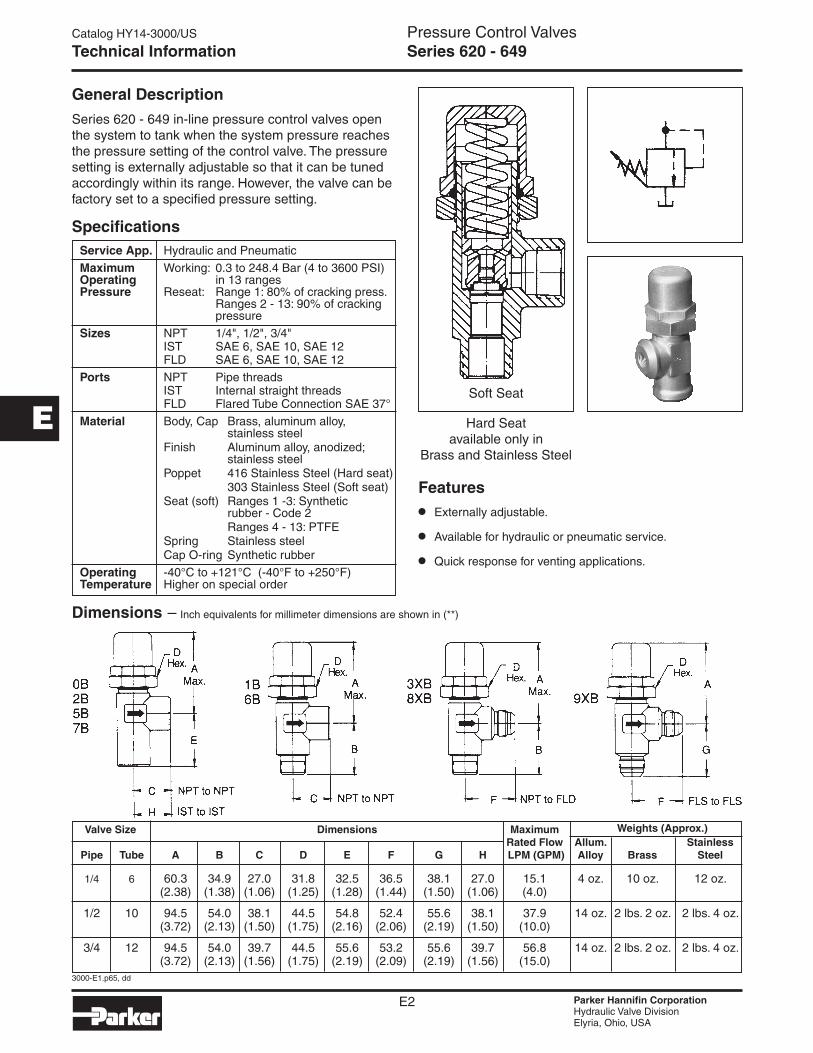
Series 620 - 649 in-line pressure control valves open the system to tank when the system pressure reaches the pressure setting of the control valve. The pressure setting is externally adjustable so that it can be tuned accordingly within its range. However, the valve can be factory set to a specified pressure setting.
Specifications
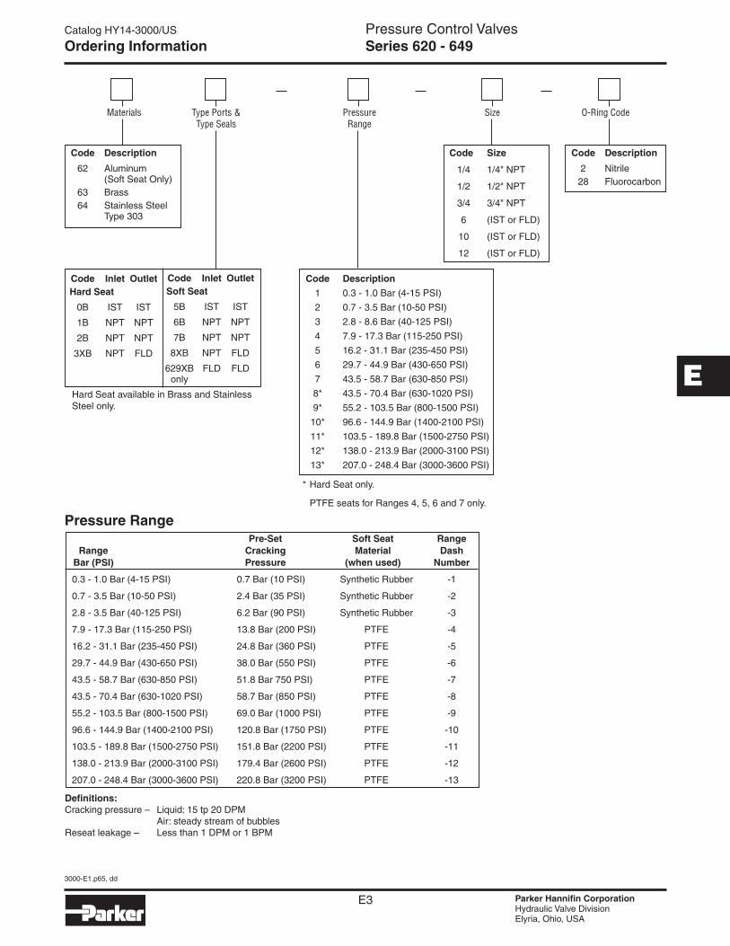
Dimensions –
Valve Size Dimensions Maximum Weights (Approx.) Rated Flow Allum. Stainless Pipe Tube A B C D E F G H LPM (GPM) Alloy Brass Steel
1/4 6 60.3 34.9 27.0 31.8 32.5 36.5 38.1 27.0 15.1 4 oz. 10 oz. 12 oz. (2.38) (1.38) (1.06) (1.25) (1.28) (1.44) (1.50) (1.06) (4.0)
1/2 10 94.5 54.0 38.1 44.5 54.8 52.4 55.6 38.1 37.9 14 oz. 2 lbs. 2 oz. 2 lbs. 4 oz. (3.72) (2.13) (1.50) (1.75) (2.16) (2.06) (2.19) (1.50) (10.0)
3/4 12 94.5 54.0 39.7 44.5 55.6 53.2 55.6 39.7 56.8 14 oz. 2 lbs. 2 oz. 2 lbs. 4 oz. (3.72) (2.13) (1.56) (1.75) (2.19) (2.09) (2.19) (1.56) (15.0)
Service App. Hydraulic and Pneumatic
Maximum Working: 0.3 to 248.4 Bar (4 to 3600 PSI) Operating in 13 ranges Pressure Reseat: Range 1: 80% of cracking press. Ranges 2 - 13: 90% of cracking pressure
Sizes NPT 1/4", 1/2", 3/4" IST SAE 6, SAE 10, SAE 12 FLD SAE 6, SAE 10, SAE 12
Ports NPT Pipe threads IST Internal straight threads FLD Flared Tube Connection SAE 37°
Material Body, Cap Brass, aluminum alloy, stainless steel Finish Aluminum alloy, anodized; stainless steel Poppet 416 Stainless Steel (Hard seat) 303 Stainless Steel (Soft seat) Seat (soft) Ranges 1 -3: Synthetic rubber - Code 2 Ranges 4 - 13: PTFE Spring Stainless steel Cap O-ring Synthetic rubber
Operating -40°C to +121°C (-40°F to +250°F) Temperature Higher on special order
Features
• Externally adjustable.
• Available for hydraulic or pneumatic service.
• Quick response for venting applications.
Soft Seat
Hard Seat available only in
Brass and Stainless Steel
Inch equivalents for millimeter dimensions are shown in (**)
Catalog HY14-3000/US
3000-E1.p65, dd
E3 Parker Hannifin CorporationHydraulic Valve DivisionElyria, Ohio, USA
Pressure Control Valves
E
Materials Type Ports & Type Seals
SizePressure Range
O-Ring Code
Hard Seat available in Brass and Stainless Steel only.
Code Description
2 Nitrile 28 Fluorocarbon
Code Size
1/4 1/4" NPT
1/2 1/2" NPT
3/4 3/4" NPT
6 (IST or FLD)
10 (IST or FLD)
12 (IST or FLD)
Code Description
1 0.3 - 1.0 Bar (4-15 PSI)
2 0.7 - 3.5 Bar (10-50 PSI)
3 2.8 - 8.6 Bar (40-125 PSI)
4 7.9 - 17.3 Bar (115-250 PSI)
5 16.2 - 31.1 Bar (235-450 PSI)
6 29.7 - 44.9 Bar (430-650 PSI)
7 43.5 - 58.7 Bar (630-850 PSI)
8* 43.5 - 70.4 Bar (630-1020 PSI)
9* 55.2 - 103.5 Bar (800-1500 PSI)
10* 96.6 - 144.9 Bar (1400-2100 PSI)
11* 103.5 - 189.8 Bar (1500-2750 PSI)
12* 138.0 - 213.9 Bar (2000-3100 PSI)
13* 207.0 - 248.4 Bar (3000-3600 PSI)
Code Inlet Outlet Hard Seat
0B IST IST
1B NPT NPT
2B NPT NPT
3XB NPT FLD
Code Description
62 Aluminum (Soft Seat Only) 63 Brass 64 Stainless Steel Type 303
Code Inlet Outlet Soft Seat
5B IST IST
6B NPT NPT
7B NPT NPT
8XB NPT FLD
629XB FLD FLD only
Pre-Set Soft Seat Range Range Cracking Material Dash Bar (PSI) Pressure (when used) Number
0.3 - 1.0 Bar (4-15 PSI) 0.7 Bar (10 PSI) Synthetic Rubber -1
0.7 - 3.5 Bar (10-50 PSI) 2.4 Bar (35 PSI) Synthetic Rubber -2
2.8 - 3.5 Bar (40-125 PSI) 6.2 Bar (90 PSI) Synthetic Rubber -3
7.9 - 17.3 Bar (115-250 PSI) 13.8 Bar (200 PSI) PTFE -4
16.2 - 31.1 Bar (235-450 PSI) 24.8 Bar (360 PSI) PTFE -5
29.7 - 44.9 Bar (430-650 PSI) 38.0 Bar (550 PSI) PTFE -6
43.5 - 58.7 Bar (630-850 PSI) 51.8 Bar 750 PSI) PTFE -7
43.5 - 70.4 Bar (630-1020 PSI) 58.7 Bar (850 PSI) PTFE -8
55.2 - 103.5 Bar (800-1500 PSI) 69.0 Bar (1000 PSI) PTFE -9
96.6 - 144.9 Bar (1400-2100 PSI) 120.8 Bar (1750 PSI) PTFE -10
103.5 - 189.8 Bar (1500-2750 PSI) 151.8 Bar (2200 PSI) PTFE -11
138.0 - 213.9 Bar (2000-3100 PSI) 179.4 Bar (2600 PSI) PTFE -12
207.0 - 248.4 Bar (3000-3600 PSI) 220.8 Bar (3200 PSI) PTFE -13
* Hard Seat only.
PTFE seats for Ranges 4, 5, 6 and 7 only.
Pressure Range
Ordering Information Series 620 - 649
Definitions:Cracking pressure – Liquid: 15 tp 20 DPM Air: steady stream of bubblesReseat leakage – Less than 1 DPM or 1 BPM

Catalog HY14-3000/US
3000-E1.p65, dd
E4 Parker Hannifin CorporationHydraulic Valve DivisionElyria, Ohio, USA
Pressure Control Valves
E
Performance Curves Series 620 - 649
ExamplesPneumatic:Establish cracking pressure setting of 1/2" valve for flow of 70 SCFM at 27.6 Bar (400 PSI) pressure:1. Project 70 SCFM on vertical scale.2. Project 27.6 Bar (400 PSI) scale horizontally inter-
sectiong 1.3. Project line parallel to curves back to vertical line 1.4. Read cracking pressure setting: 24.8 Bar (360 PSI).
Hydraulic:Find amount of pressure increase above 24.8 Bar (360 PSI) cracking pressure when flow through 3/4" valve is increased to 54 LPM (14 GPM):1. From 360 on vertical pressure scale, follow
3/4" curve until it intersects with the vertical line representing 54 LPM (14 GPM).
2. Project intersecting point horizontally and read pressure, i.e., 29 Bar (420 PSI).
3. Accumulated Pressure: 420 minus 360 = 4.1 Bar (60 PSI).
Rate of Flow SCFM Rate of Flow GPM
FactorySetting
FactorySetting
PressurePSI
PressurePSI
RangePSI
DashNo.Flow Capacity Flow Capacity
2600 26003200 32003100
to2000
2750to
1500
2100to
1400
1500to
800
1020to
630
850to
630
650to
430
450to
235
250to
115
125to40
50to10
15to4
2800 2800
2200 2200
1300 1300
1000 1000
825 825
640 640
420 420
230 230
120 120
50 50
22 22
3000 300012
2600 260011
2050 205010
1200 12009
950 9508
800 8007
610 6106
400 4005
220 2204
110 1103
45 452
18 181
2800 2800
2400 2400
1900 1900
1100 1100
900 900
775 775
580 580
380 380
210 210
100 100
40 40
40 40
2200 2200
1750 1750
1000 1000
850 850
550 550
360 360
200 200
90
1 02 23 5 410 620 850 10 12 14 16 18 20100 200 500
90
35 35
1/2", 3/4"1/8", 1/4", 3/8"
10 10
750 750
Catalog HY14-3000/US
3000-E1.p65, dd
E5 Parker Hannifin CorporationHydraulic Valve DivisionElyria, Ohio, USA
Pressure Control Valves
E
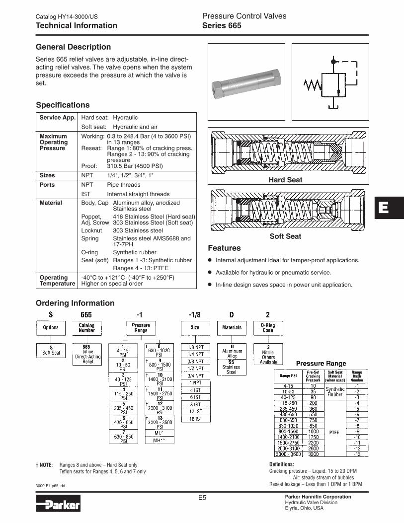
Technical Information Series 665
General Description
Series 665 relief valves are adjustable, in-line direct- acting relief valves. The valve opens when the system pressure exceeds the pressure at which the valve is set.
Features
• Internal adjustment ideal for tamper-proof applications.
• Available for hydraulic or pneumatic service.
• In-line design saves space in power unit application.
† NOTE: Ranges 8 and above – Hard Seat only Teflon seats for Ranges 4, 5, 6 and 7 only
Definitions:Cracking pressure – Liquid: 15 to 20 DPM Air: steady stream of bubblesReseat leakage – Less than 1 DPM or 1 BPM
Ordering Information
Nitrile
PTFE
Service App. Hard seat: Hydraulic
Soft seat: Hydraulic and air
Maximum Working: 0.3 to 248.4 Bar (4 to 3600 PSI) Operating in 13 ranges Pressure Reseat: Range 1: 80% of cracking press. Ranges 2 - 13: 90% of cracking pressure Proof: 310.5 Bar (4500 PSI)
Sizes NPT 1/4", 1/2", 3/4", 1"
Ports NPT Pipe threads
IST Internal straight threads
Material Body, Cap Aluminum alloy, anodized Stainless steel Poppet, 416 Stainless Steel (Hard seat) Adj. Screw 303 Stainless Steel (Soft seat) Locknut 303 Stainless steel Spring Stainless steel AMS5688 and 17-7PH O-ring Synthetic rubber Seat (soft) Ranges 1 -3: Synthetic rubber Ranges 4 - 13: PTFE
Operating -40°C to +121°C (-40°F to +250°F) Temperature Higher on special order
Specifications
Soft Seat
Hard Seat
Catalog HY14-3000/US
3000-E1.p65, dd
E6 Parker Hannifin CorporationHydraulic Valve DivisionElyria, Ohio, USA
Pressure Control Valves
E
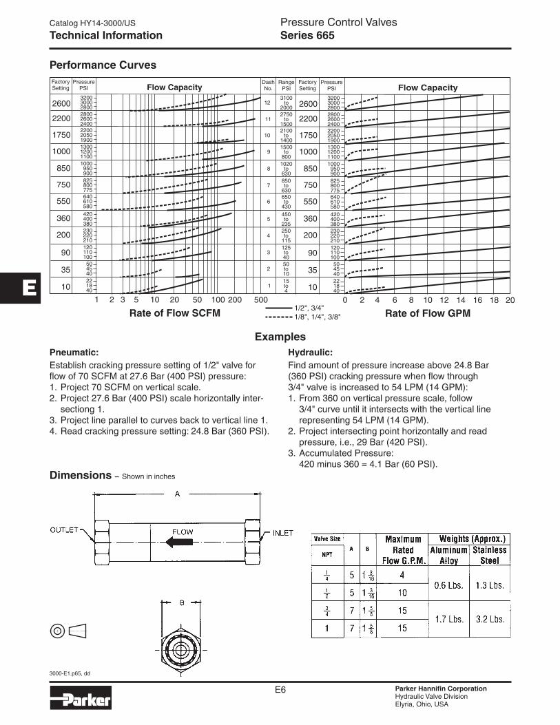
Technical Information Series 665
ExamplesPneumatic:Establish cracking pressure setting of 1/2" valve for flow of 70 SCFM at 27.6 Bar (400 PSI) pressure:1. Project 70 SCFM on vertical scale.2. Project 27.6 Bar (400 PSI) scale horizontally inter-
sectiong 1.3. Project line parallel to curves back to vertical line 1.4. Read cracking pressure setting: 24.8 Bar (360 PSI).
Hydraulic:Find amount of pressure increase above 24.8 Bar (360 PSI) cracking pressure when flow through 3/4" valve is increased to 54 LPM (14 GPM):1. From 360 on vertical pressure scale, follow
3/4" curve until it intersects with the vertical line representing 54 LPM (14 GPM).
2. Project intersecting point horizontally and read pressure, i.e., 29 Bar (420 PSI).
3. Accumulated Pressure: 420 minus 360 = 4.1 Bar (60 PSI).
Dimensions – Shown in inches
Performance Curves
Rate of Flow SCFM Rate of Flow GPM
FactorySetting
FactorySetting
PressurePSI
PressurePSI
RangePSI
DashNo.Flow Capacity Flow Capacity
2600 26003200 32003100
to20002750
to15002100
to14001500
to800
1020to
630850to
630650to
430450to
235250to
115125to4050to1015to4
2800 2800
2200 2200
1300 1300
1000 1000
825 825
640 640
420 420
230 230
120 120
50 50
22 22
3000 300012
2600 260011
2050 205010
1200 12009
950 9508
800 8007
610 6106
400 4005
220 2204
110 1103
45 452
18 181
2800 2800
2400 2400
1900 1900
1100 1100
900 900
775 775
580 580
380 380
210 210
100 100
40 40
40 40
2200 2200
1750 1750
1000 1000
850 850
550 550
360 360
200 200
90
1 02 23 5 410 620 850 10 12 14 16 18 20100 200 500
90
35 35
1/2", 3/4"1/8", 1/4", 3/8"
10 10
750 750
Catalog HY14-3000/US
3000-E1.p65, dd
E7 Parker Hannifin CorporationHydraulic Valve DivisionElyria, Ohio, USA
Pressure Control Valves
E
Series RA
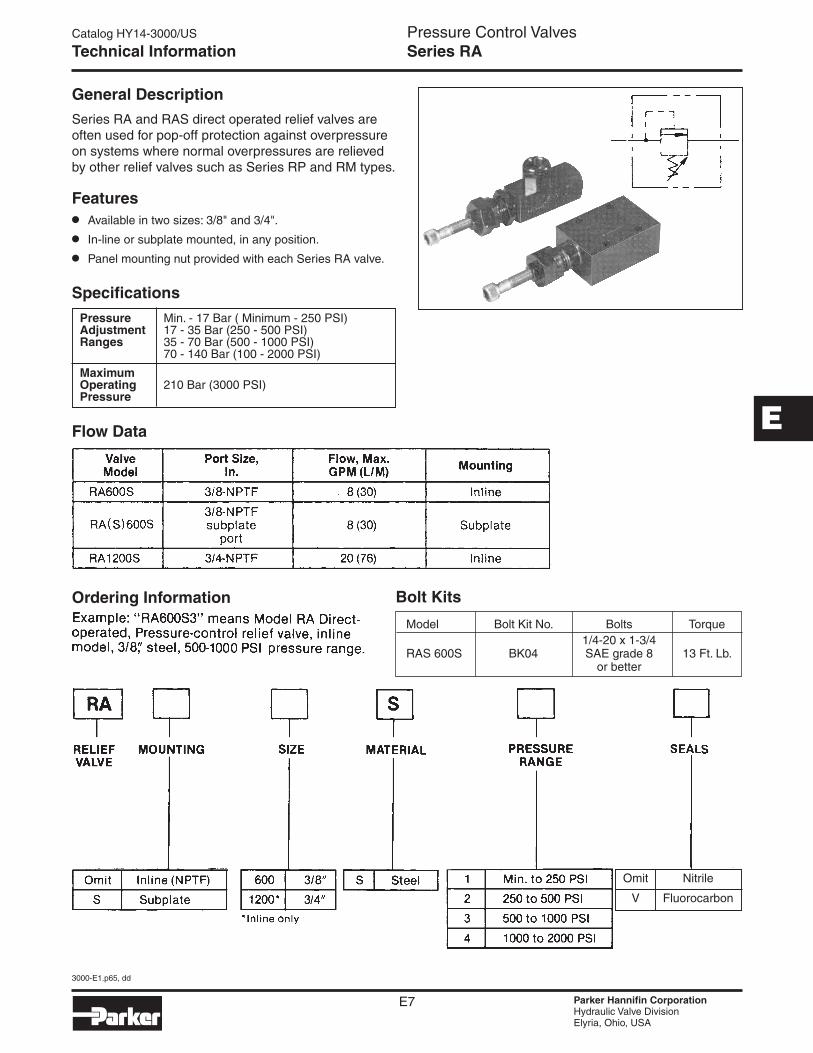
Model Bolt Kit No. Bolts Torque 1/4-20 x 1-3/4 RAS 600S BK04 SAE grade 8 13 Ft. Lb. or better
Technical Information
Flow Data
General Description
Series RA and RAS direct operated relief valves are often used for pop-off protection against overpressure on systems where normal overpressures are relieved by other relief valves such as Series RP and RM types.
Pressure Min. - 17 Bar ( Minimum - 250 PSI)I) Adjustment 17 - 35 Bar (250 - 500 PSI) Ranges 35 - 70 Bar (500 - 1000 PSI) 70 - 140 Bar (100 - 2000 PSI)
Maximum Operating 210 Bar (3000 PSI) Pressure
Specifications
Ordering Information Bolt Kits
Features• Available in two sizes: 3/8" and 3/4".
• In-line or subplate mounted, in any position.
• Panel mounting nut provided with each Series RA valve.
Omit Nitrile
V Fluorocarbon

Catalog HY14-3000/US
3000-E1.p65, dd
E8 Parker Hannifin CorporationHydraulic Valve DivisionElyria, Ohio, USA
Pressure Control Valves
E
Technical Information Series RA
DimensionsMillimeter equivalents for inch dimensions are shown in (**)
Performance Curves
Catalog HY14-3000/US
3000-E1.p65, dd
E9 Parker Hannifin CorporationHydraulic Valve DivisionElyria, Ohio, USA
Pressure Control Valves
E
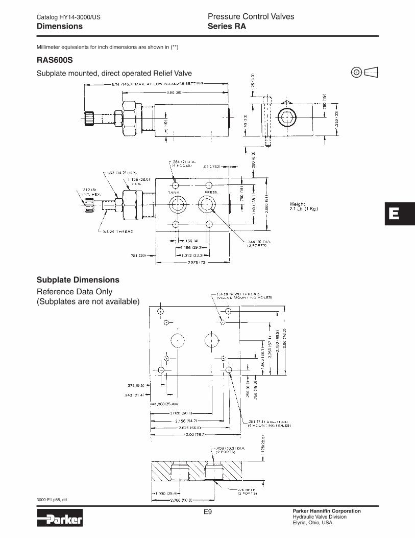
Dimensions
Subplate DimensionsReference Data Only (Subplates are not available)
DimensionsMillimeter equivalents for inch dimensions are shown in (**)
RAS600S
Subplate mounted, direct operated Relief Valve
Series RA
Catalog HY14-3000/US
3000-E1.p65, dd
E10 Parker Hannifin CorporationHydraulic Valve DivisionElyria, Ohio, USA
Pressure Control Valves
E
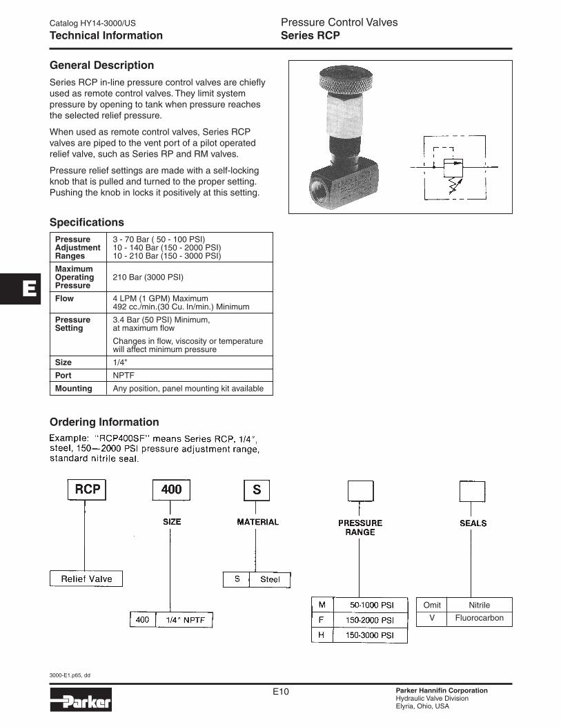
Technical Information Series RCP
General Description
Series RCP in-line pressure control valves are chiefly used as remote control valves. They limit system pressure by opening to tank when pressure reaches the selected relief pressure.
When used as remote control valves, Series RCP valves are piped to the vent port of a pilot operated relief valve, such as Series RP and RM valves.
Pressure relief settings are made with a self-locking knob that is pulled and turned to the proper setting. Pushing the knob in locks it positively at this setting.
Pressure 3 - 70 Bar ( 50 - 100 PSI)I) Adjustment 10 - 140 Bar (150 - 2000 PSI) Ranges 10 - 210 Bar (150 - 3000 PSI)
Maximum Operating 210 Bar (3000 PSI) Pressure
Flow 4 LPM (1 GPM) Maximum 492 cc./min.(30 Cu. In/min.) Minimum
Pressure 3.4 Bar (50 PSI) Minimum, Setting at maximum flow
Changes in flow, viscosity or temperature will affect minimum pressure
Size 1/4"
Port NPTF
Mounting Any position, panel mounting kit available
Specifications
Ordering Information
Omit Nitrile
V Fluorocarbon
Catalog HY14-3000/US
3000-E1.p65, dd
E11 Parker Hannifin CorporationHydraulic Valve DivisionElyria, Ohio, USA
Pressure Control Valves
E
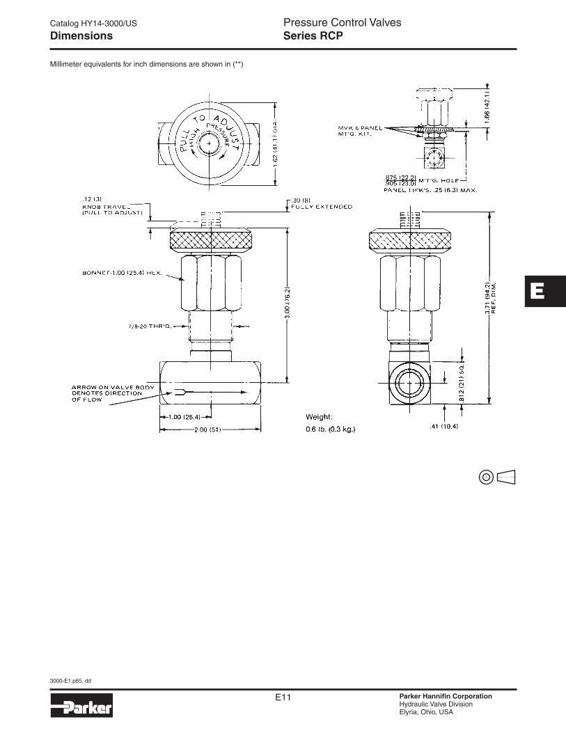
Dimensions Series RCP
Millimeter equivalents for inch dimensions are shown in (**)
Catalog HY14-3000/US
3000-E1.p65, dd
E12 Parker Hannifin CorporationHydraulic Valve DivisionElyria, Ohio, USA
Pressure Control Valves
E
Technical Information
Flow Data
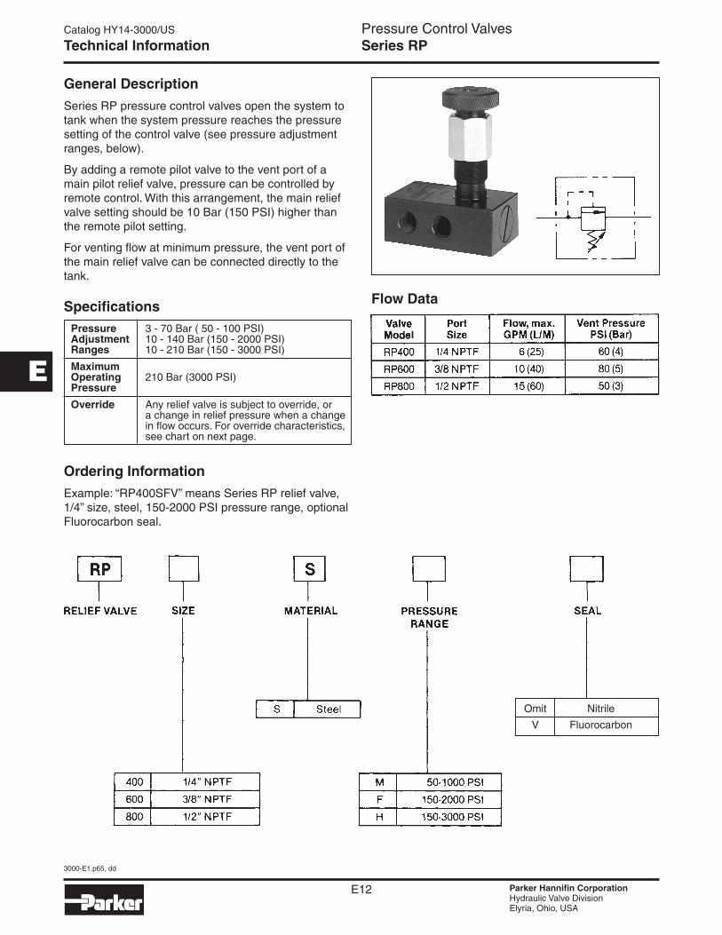
Series RP
General Description
Series RP pressure control valves open the system to tank when the system pressure reaches the pressure setting of the control valve (see pressure adjustment ranges, below).
By adding a remote pilot valve to the vent port of a main pilot relief valve, pressure can be controlled by remote control. With this arrangement, the main relief valve setting should be 10 Bar (150 PSI) higher than the remote pilot setting.
For venting flow at minimum pressure, the vent port of the main relief valve can be connected directly to the tank.
Pressure 3 - 70 Bar ( 50 - 100 PSI)I) Adjustment 10 - 140 Bar (150 - 2000 PSI) Ranges 10 - 210 Bar (150 - 3000 PSI)
Maximum Operating 210 Bar (3000 PSI) Pressure
Override Any relief valve is subject to override, or a change in relief pressure when a change in flow occurs. For override characteristics, see chart on next page.
Specifications
Ordering Information
Example: “RP400SFV” means Series RP relief valve, 1/4” size, steel, 150-2000 PSI pressure range, optional Fluorocarbon seal.
Omit Nitrile
V Fluorocarbon
Catalog HY14-3000/US
3000-E1.p65, dd
E13 Parker Hannifin CorporationHydraulic Valve DivisionElyria, Ohio, USA
Pressure Control Valves
E
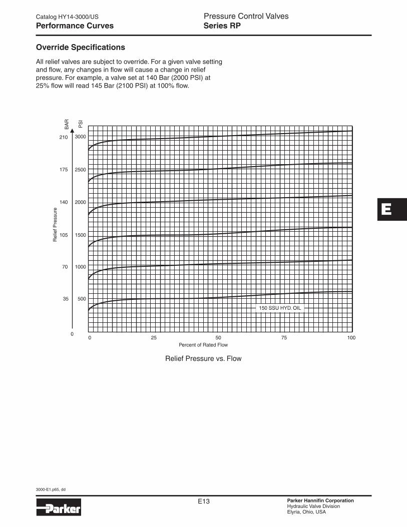
Performance Curves Series RP
Override Specifications
All relief valves are subject to override. For a given valve setting and flow, any changes in flow will cause a change in relief pressure. For example, a valve set at 140 Bar (2000 PSI) at 25% flow will read 145 Bar (2100 PSI) at 100% flow.
Catalog HY14-3000/US
3000-E1.p65, dd
E14 Parker Hannifin CorporationHydraulic Valve DivisionElyria, Ohio, USA
Pressure Control Valves
E
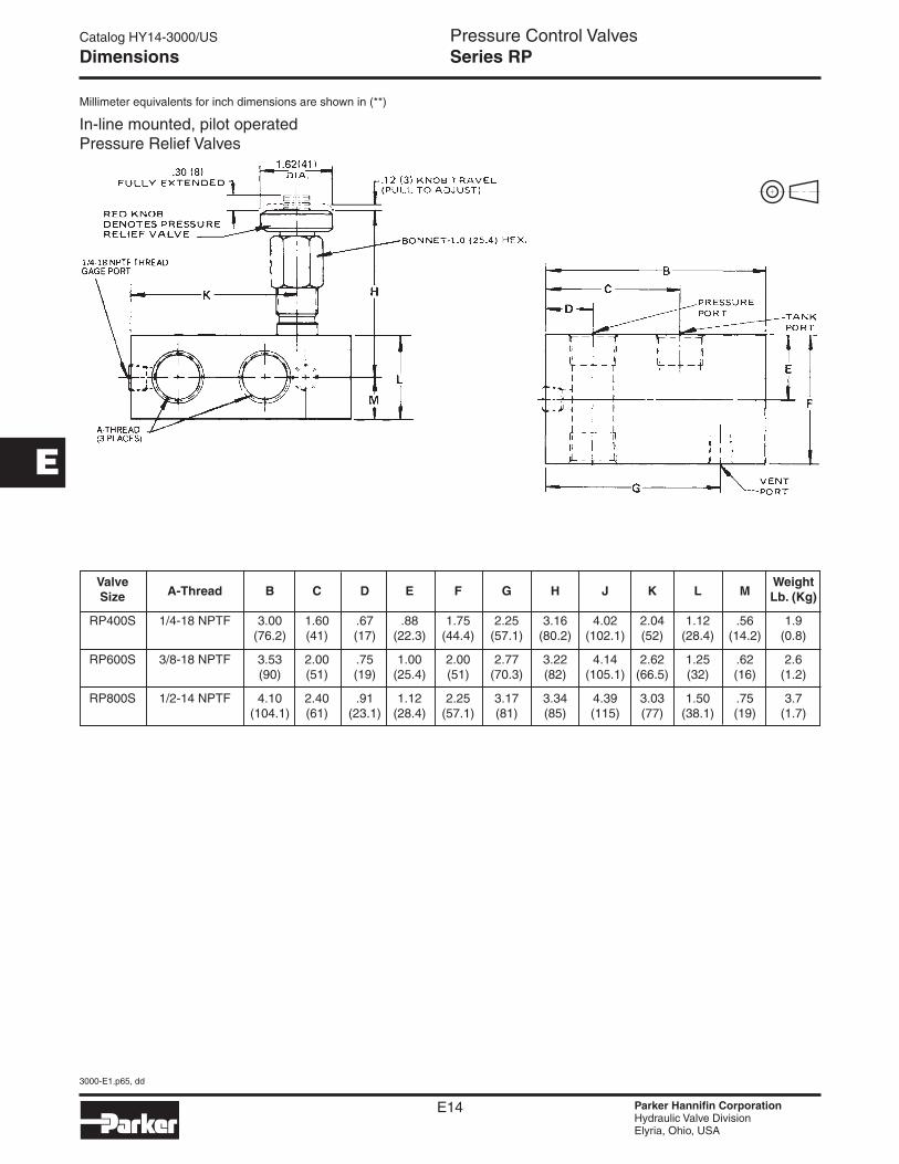
Dimensions
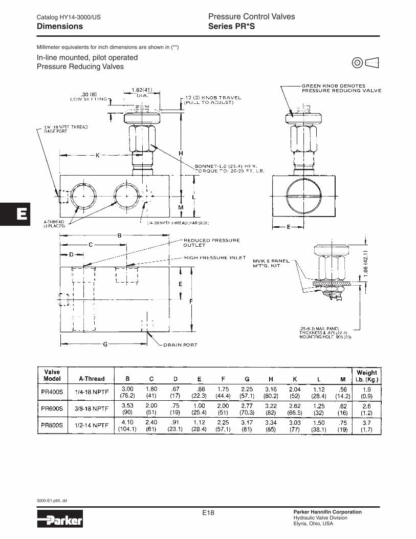
Valve Weight Size A-Thread B C D E F G H J K L M Lb. (Kg)
RP400S 1/4-18 NPTF 3.00 1.60 .67 .88 1.75 2.25 3.16 4.02 2.04 1.12 .56 1.9 (76.2) (41) (17) (22.3) (44.4) (57.1) (80.2) (102.1) (52) (28.4) (14.2) (0.8)
RP600S 3/8-18 NPTF 3.53 2.00 .75 1.00 2.00 2.77 3.22 4.14 2.62 1.25 .62 2.6 (90) (51) (19) (25.4) (51) (70.3) (82) (105.1) (66.5) (32) (16) (1.2)
RP800S 1/2-14 NPTF 4.10 2.40 .91 1.12 2.25 3.17 3.34 4.39 3.03 1.50 .75 3.7 (104.1) (61) (23.1) (28.4) (57.1) (81) (85) (115) (77) (38.1) (19) (1.7)
DimensionsMillimeter equivalents for inch dimensions are shown in (**)
In-line mounted, pilot operated Pressure Relief Valves
Series RP
Catalog HY14-3000/US
3000-E1.p65, dd
E15 Parker Hannifin CorporationHydraulic Valve DivisionElyria, Ohio, USA
Pressure Control Valves
E
Technical Information Series R6701
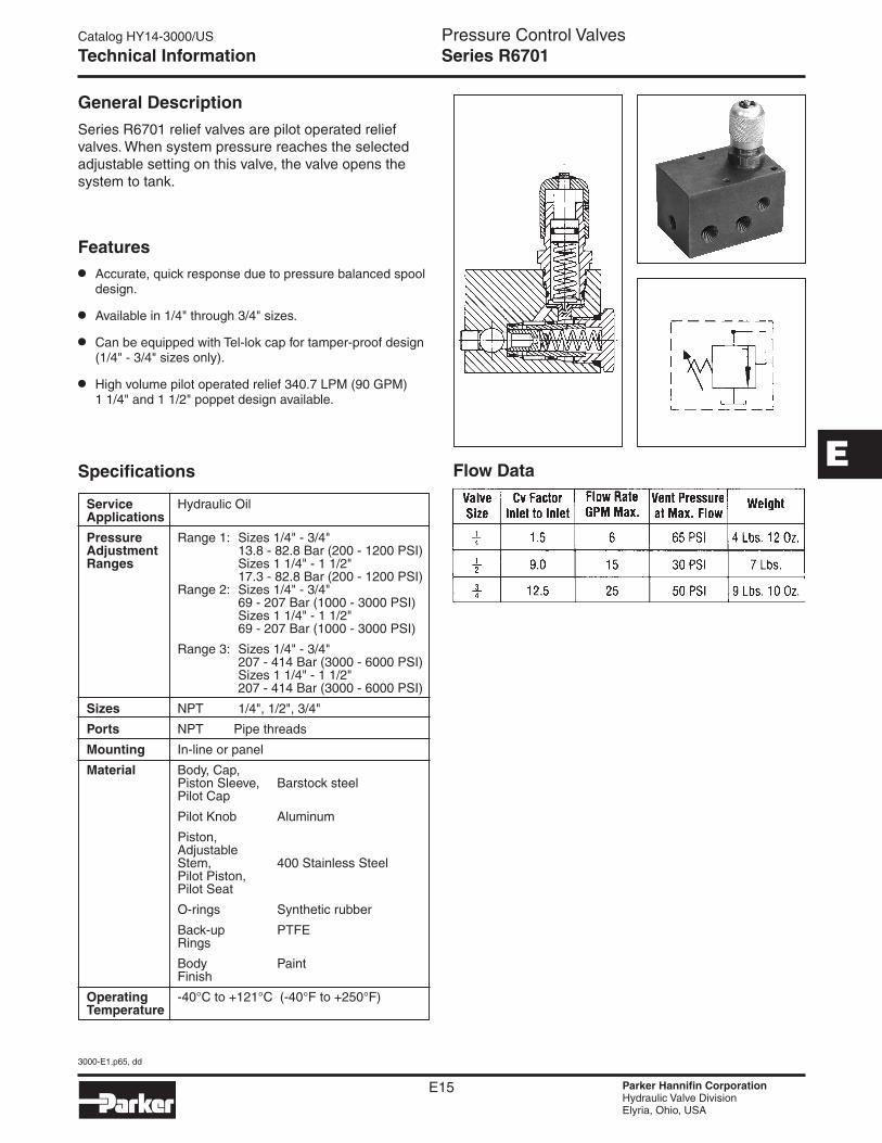
General Description
Series R6701 relief valves are pilot operated relief valves. When system pressure reaches the selected adjustable setting on this valve, the valve opens the system to tank.
Service Hydraulic Oil Applications
Pressure Range 1: Sizes 1/4" - 3/4" Adjustment 13.8 - 82.8 Bar (200 - 1200 PSI) Ranges Sizes 1 1/4" - 1 1/2" 17.3 - 82.8 Bar (200 - 1200 PSI) Range 2: Sizes 1/4" - 3/4" 69 - 207 Bar (1000 - 3000 PSI) Sizes 1 1/4" - 1 1/2" 69 - 207 Bar (1000 - 3000 PSI)
Range 3: Sizes 1/4" - 3/4" 207 - 414 Bar (3000 - 6000 PSI) Sizes 1 1/4" - 1 1/2" 207 - 414 Bar (3000 - 6000 PSI)
Sizes NPT 1/4", 1/2", 3/4"
Ports NPT Pipe threads
Mounting In-line or panel
Material Body, Cap, Piston Sleeve, Barstock steel Pilot Cap
Pilot Knob Aluminum
Piston, Adjustable Stem, 400 Stainless Steel Pilot Piston, Pilot Seat
O-rings Synthetic rubber
Back-up PTFE Rings
Body Paint Finish
Operating -40°C to +121°C (-40°F to +250°F) Temperature
Features
• Accurate, quick response due to pressure balanced spool design.
• Available in 1/4" through 3/4" sizes.
• Can be equipped with Tel-lok cap for tamper-proof design (1/4" - 3/4" sizes only).
• High volume pilot operated relief 340.7 LPM (90 GPM) 1 1/4" and 1 1/2" poppet design available.
Flow DataSpecifications
Catalog HY14-3000/US
3000-E1.p65, dd
E16 Parker Hannifin CorporationHydraulic Valve DivisionElyria, Ohio, USA
Pressure Control Valves
E
Technical Information Series R6701
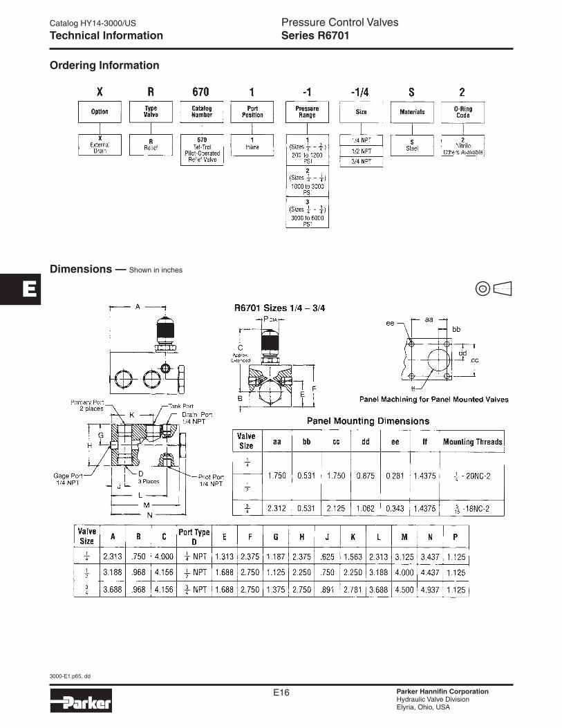
Ordering Information
Dimensions — Shown in inches
Catalog HY14-3000/US
3000-E1.p65, dd
E17 Parker Hannifin CorporationHydraulic Valve DivisionElyria, Ohio, USA
Pressure Control Valves
E
Technical Information Series PR*S
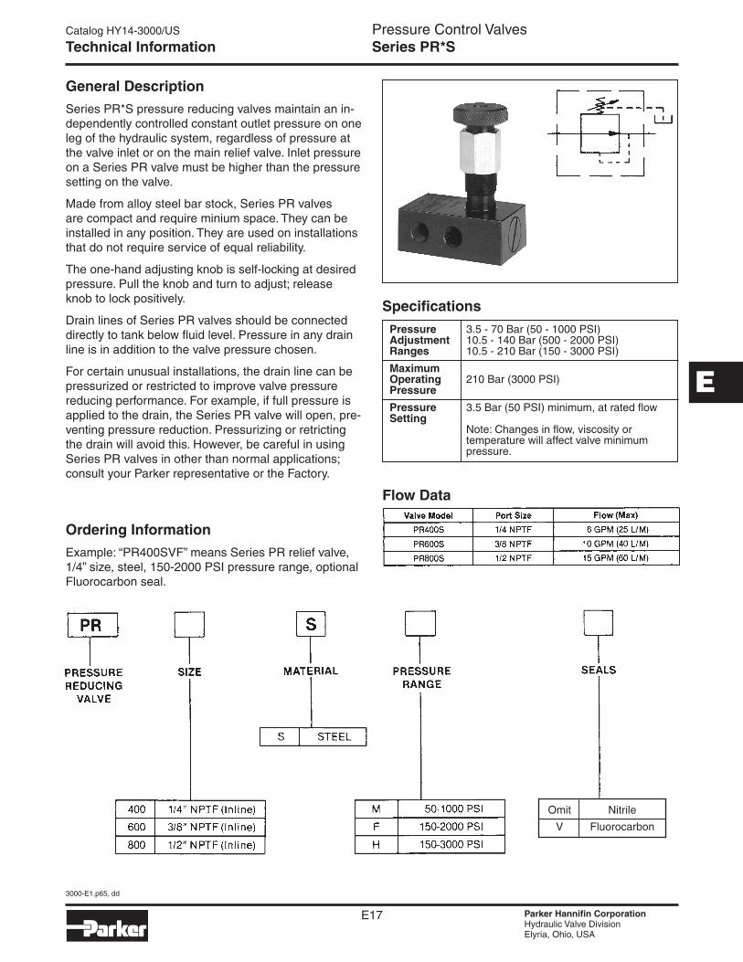
General Description
Series PR*S pressure reducing valves maintain an in-dependently controlled constant outlet pressure on one leg of the hydraulic system, regardless of pressure at the valve inlet or on the main relief valve. Inlet pressure on a Series PR valve must be higher than the pressure setting on the valve.
Made from alloy steel bar stock, Series PR valves are compact and require minium space. They can be installed in any position. They are used on installations that do not require service of equal reliability.
The one-hand adjusting knob is self-locking at desired pressure. Pull the knob and turn to adjust; release knob to lock positively.
Drain lines of Series PR valves should be connected directly to tank below fluid level. Pressure in any drain line is in addition to the valve pressure chosen.
For certain unusual installations, the drain line can be pressurized or restricted to improve valve pressure reducing performance. For example, if full pressure is applied to the drain, the Series PR valve will open, pre-venting pressure reduction. Pressurizing or retricting the drain will avoid this. However, be careful in using Series PR valves in other than normal applications; consult your Parker representative or the Factory.
Ordering Information
Example: “PR400SVF” means Series PR relief valve, 1/4” size, steel, 150-2000 PSI pressure range, optional Fluorocarbon seal.
Flow Data
Pressure 3.5 - 70 Bar (50 - 1000 PSI) Adjustment 10.5 - 140 Bar (500 - 2000 PSI) Ranges 10.5 - 210 Bar (150 - 3000 PSI)
Maximum Operating 210 Bar (3000 PSI) Pressure
Pressure 3.5 Bar (50 PSI) minimum, at rated flow Setting Note: Changes in flow, viscosity or temperature will affect valve minimum pressure.
Specifications
Omit Nitrile
V Fluorocarbon
Catalog HY14-3000/US
3000-E1.p65, dd
E18 Parker Hannifin CorporationHydraulic Valve DivisionElyria, Ohio, USA
Pressure Control Valves
E
Dimensions Series PR*S
Millimeter equivalents for inch dimensions are shown in (**)
In-line mounted, pilot operated Pressure Reducing Valves
Catalog HY14-3000/US
3000-E1.p65, dd
E19 Parker Hannifin CorporationHydraulic Valve DivisionElyria, Ohio, USA
Pressure Control Valves
E
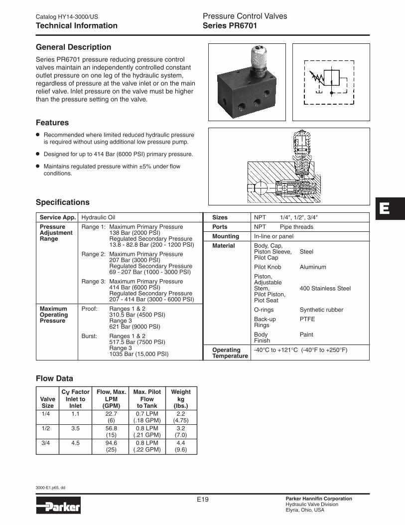
Technical Information Series PR6701
Features
• Recommended where limited reduced hydraulic pressure is required without using additional low pressure pump.
• Designed for up to 414 Bar (6000 PSI) primary pressure.
• Maintains regulated pressure within ±5% under flow conditions.
Service App. Hydraulic Oil
Pressure Range 1: Maximum Primary Pressure Adjustment 138 Bar (2000 PSI) Range Regulated Secondary Pressure 13.8 - 82.8 Bar (200 - 1200 PSI)
Range 2: Maximum Primary Pressure 207 Bar (3000 PSI) Regulated Secondary Pressure 69 - 207 Bar (1000 - 3000 PSI)
Range 3: Maximum Primary Pressure 414 Bar (6000 PSI) Regulated Secondary Pressure 207 - 414 Bar (3000 - 6000 PSI)
Maximum Proof: Ranges 1 & 2 Operating 310.5 Bar (4500 PSI) Pressure Range 3 621 Bar (9000 PSI)
Burst: Ranges 1 & 2 517.5 Bar (7500 PSI) Range 3 1035 Bar (15,000 PSI)
Specifications
General Description
Series PR6701 pressure reducing pressure control valves maintain an independently controlled constant outlet pressure on one leg of the hydraulic system, regardless of pressure at the valve inlet or on the main relief valve. Inlet pressure on the valve must be higher than the pressure setting on the valve.
Sizes NPT 1/4", 1/2", 3/4"
Ports NPT Pipe threads
Mounting In-line or panel
Material Body, Cap, Piston Sleeve, Steel Pilot Cap
Pilot Knob Aluminum
Piston, Adjustable Stem, 400 Stainless Steel Pilot Piston, Piot Seat
O-rings Synthetic rubber
Back-up PTFE Rings
Body Paint Finish
Operating -40°C to +121°C (-40°F to +250°F) Temperature
Flow Data
CV Factor Flow, Max. Max. Pilot Weight Valve Inlet to LPM Flow kg Size Inlet (GPM) to Tank (lbs.) 1/4 1.1 22.7 0.7 LPM 2.2 (6) (.18 GPM) (4.75) 1/2 3.5 56.8 0.8 LPM 3.2 (15) (.21 GPM) (7.0) 3/4 4.5 94.6 0.8 LPM 4.4 (25) (.22 GPM) (9.6)
Catalog HY14-3000/US
3000-E1.p65, dd
E20 Parker Hannifin CorporationHydraulic Valve DivisionElyria, Ohio, USA
Pressure Control Valves
E
Technical Information Series PR6701
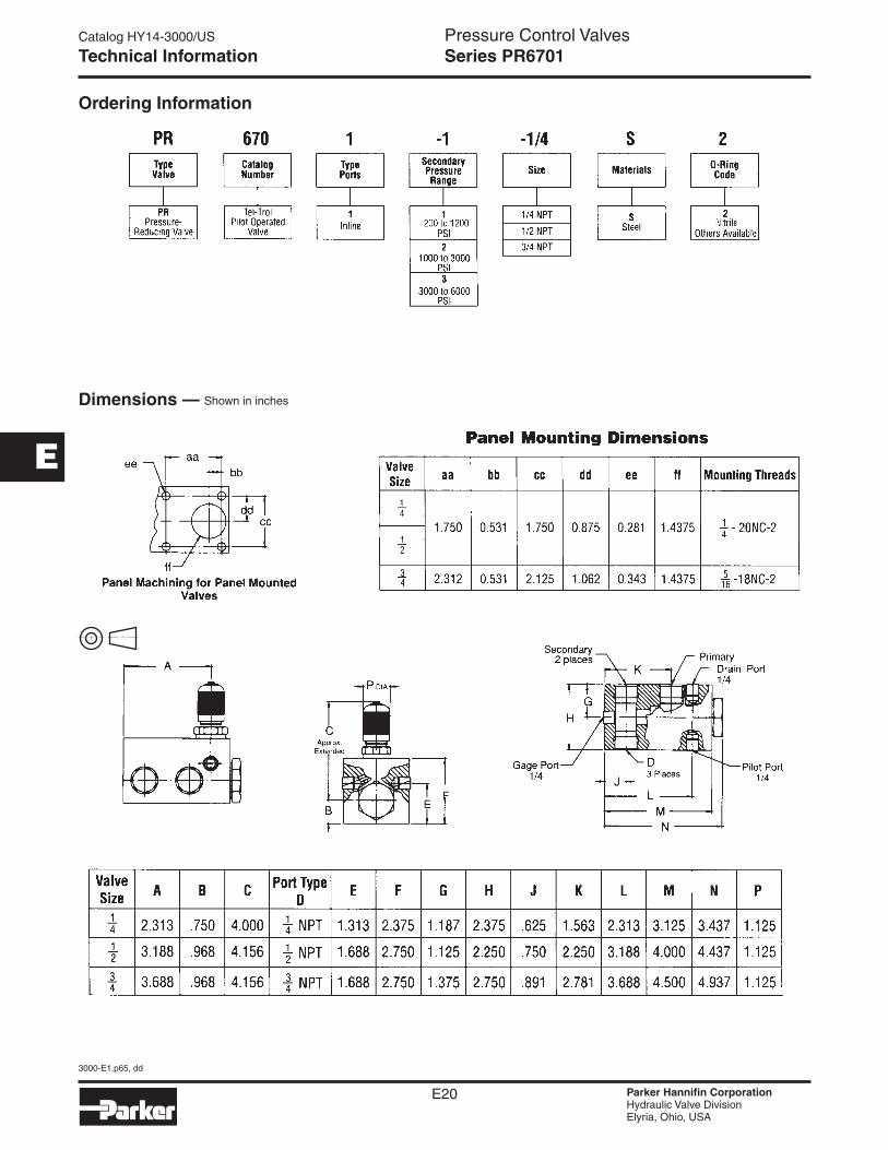
Ordering Information
Dimensions — Shown in inches
Catalog HY14-3000/US
3000-E1.p65, dd
E21 Parker Hannifin CorporationHydraulic Valve DivisionElyria, Ohio, USA
Pressure Control Valves
E
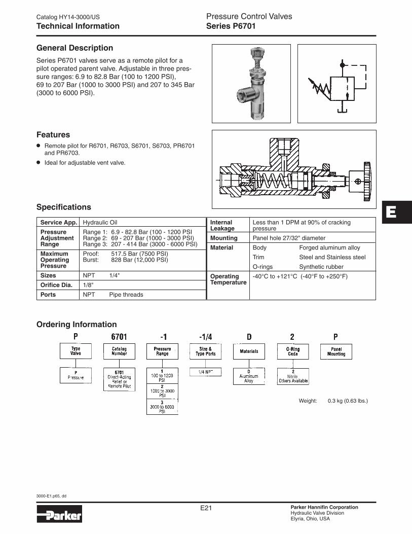
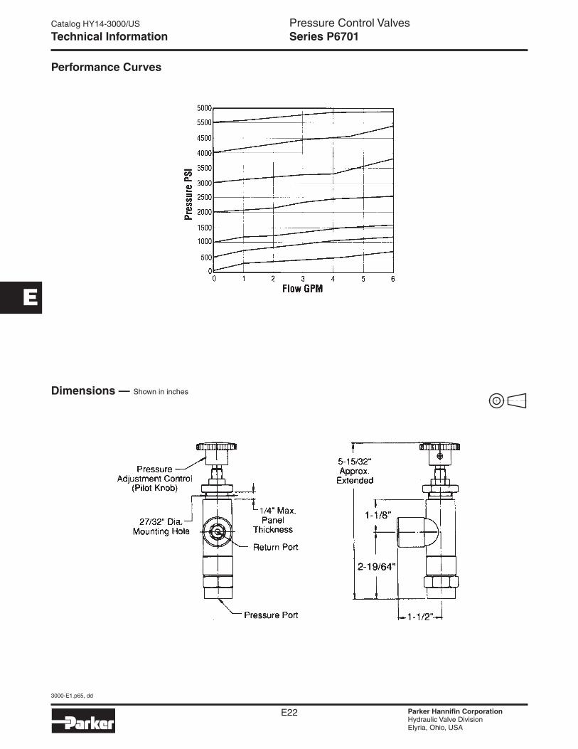
Technical Information Series P6701
Features• Remote pilot for R6701, R6703, S6701, S6703, PR6701
and PR6703.
• Ideal for adjustable vent valve.
General Description
Series P6701 valves serve as a remote pilot for a pilot operated parent valve. Adjustable in three pres-sure ranges: 6.9 to 82.8 Bar (100 to 1200 PSI), 69 to 207 Bar (1000 to 3000 PSI) and 207 to 345 Bar (3000 to 6000 PSI).
Nitrile
Ordering Information
Weight: 0.3 kg (0.63 lbs.)
Service App. Hydraulic Oil
Pressure Range 1: 6.9 - 82.8 Bar (100 - 1200 PSI Adjustment Range 2: 69 - 207 Bar (1000 - 3000 PSI) Range Range 3: 207 - 414 Bar (3000 - 6000 PSI)
Maximum Proof: 517.5 Bar (7500 PSI) Operating Burst: 828 Bar (12,000 PSI) Pressure
Sizes NPT 1/4"
Orifice Dia. 1/8"
Ports NPT Pipe threads
Specifications
Internal Less than 1 DPM at 90% of cracking Leakage pressure
Mounting Panel hole 27/32" diameter
Material Body Forged aluminum alloy
Trim Steel and Stainless steel
O-rings Synthetic rubber
Operating -40°C to +121°C (-40°F to +250°F) Temperature
Catalog HY14-3000/US
3000-E1.p65, dd
E22 Parker Hannifin CorporationHydraulic Valve DivisionElyria, Ohio, USA
Pressure Control Valves
E
Performance Curves
Dimensions —
Technical Information Series P6701
Shown in inches